


Power Supply Specification
( )
Customer ( ) TOT
Part No. ( ) PLE55-1A
Revision REV 1.1
Description( 1): 32 LED LIPS
Description( 2): 90V*300mA*1 12V/1A
Please return to us one original of “SPECIFICATION FOR APPROVAL” with your approved signatures.
APPROVED SHEET( )
APPROVED BY |
DATE |
CHOP & SIGNATURES:
6-1 516006 TEL +86-752-5349569
|
|
DATE |
PREPARED |
CHECKED |
APPROVED |
|
|
|
|
|
|
|
|
|
|
|
|
2016-6-22 |
|
|
|
|
|
|
|
|
|
|
|
|
|
|
|
|
|
|
Page 1 of 13 |
|
|
|
|
|
|
|
|
|
|

|
FILE NO. |
|
|
|
|
|
|
|
|
|
MODEL NO. |
PLE55-1A |
|
|
SPECIFICATION |
|
|
|
|
REVISION |
REV: 1.1 |
DATE |
2016-6-22 |
|
|
|
|
|
|
Revision History
Date |
Rev. |
Page |
Summary |
Revised by |
|
|
|
|
|
2016-5 -5 |
V1.0 |
|
INITIAL EDITION |
|
2016-6 -22 V1.1 4 |
0.5w |
|
2016 6 -22 V1.1 |
21 |
T375J |
|
|
|
T375HF |
Page 2 of 13

|
|
FILE NO. |
|
|
|
|
|
|
|
|
|
|
|
|
|
|
|
MODEL NO. |
PLE55-1A |
|
|
|
|
SPECIFICATION |
|
|
|
|
|
|
|
REVISION |
REV: 1.1 |
DATE |
2016-6-22 |
|
|||
|
|
|
|
|
|
|
|
|
|
|
|
|
|
|
|
|
|
|
|
|
|
|
|
|
|
Table of Contents |
|
|
|
|
|
|
|
|
|
|
|
|
|
|
|
ITEM |
|
|
|
PAGE |
|
|
|
|
|
|
|
||
|
1. ELECTRICAL SPECIFICATIONS |
|
|
4-6 |
|
||
|
|
|
|
|
|
|
|
|
2. PROTECTION |
|
|
|
6-7 |
|
|
|
|
|
|
|
|
|
|
|
3. ENVIRONMENTS |
|
|
|
7-8 |
|
|
|
|
|
|
|
|
||
|
4. SAFETY AND EMC |
|
|
8-9 |
|
||
|
|
|
|
|
|
|
|
|
5. RELIABILITIES |
|
|
|
9 |
|
|
|
|
|
|
|
|
|
|
|
6. ACOUSTICS |
|
|
|
10 |
|
|
|
|
|
|
|
|
|
|
|
7. MECHANICALS |
|
|
|
10 |
|
|
|
|
|
|
|
|
|
|
|
8. WEIGHT |
|
|
|
10 |
|
|
|
|
|
|
|
|
||
|
9. PIN CONNECTION |
|
|
10 |
|
||
|
|
|
|
|
|
|
|
|
10. OTHERS |
|
|
|
11 |
|
|
|
|
|
|
|
|
|
|
|
11. APPENDIX |
|
|
|
11 |
|
|
|
|
|
|
|
|
|
|
|
12. packaging |
|
|
|
12 |
|
|
|
|
|
|
|
|
|
|
|
13.Appendix |
|
|
|
13 |
|
|
|
|
|
|
|
|
||
|
|
|
|
|
|
|
|
|
14. |
|
|
|
14 |
|
|
|
|
|
|
|
|
|
|
|
15. BOM |
|
|
|
15-19 |
|
|
|
|
|
|
|
|
|
|
|
16, |
|
|
|
20-23 |
|
|
|
|
|
|
|
|
|
|
|
17, ROHS 2.0 |
|
|
|
24-33 |
|
|
|
|
|
|
|
|
|
|
|
|
|
|
|
|
|
|
|
|
|
|
|
|
|
|
|
|
|
|
|
|
|
|
|
|
|
|
|
|
|
|
|
|
|
|
|
|
|
|
|
|
|
|
|
|
|
|
|
|
|
|
|
|
|
|
|
|
|
|
|
|
|
|
|
|
|
|
|
|
|
|
|
|
|
|
|
|
|
|
Page 3 of 13
|
FILE NO. |
|
|
|
|
|
|
|
|
|
MODEL NO. |
PLE55-1A |
|
|
SPECIFICATION |
|
|
|
|
REVISION |
REV: 1.1 |
DATE |
2016-6-22 |
|
|
|
|
|
|
1. Electrical Specifications
AC Input Characteristics
Item |
Specification |
Condition |
|
|
|
|
|
Normal Input Voltage* |
100Vac-240Vac |
Normal working range |
|
|
|
||
|
|||
|
|
|
|
Limited Input Voltage* |
90Vac-264Vac |
Limited working range |
|
|
|
||
|
|||
|
|
|
|
Input Frequency |
47Hz-63Hz |
|
|
|
|
||
|
|
||
|
|
|
|
Max. Input AC Current |
2A Max. |
Min input and full load |
|
|
|||
|
|
||
|
|
|
|
Inrush Current |
50A peak |
110Vac Cold start |
|
|
80A peak |
220Vac Cold start |
|
|
|
|
|
Efficiency (Full Load) |
75% typ |
230Vac Full load |
|
|
|||
|
|
||
|
|
|
|
Leakage Current |
0.35mA Max. |
230Vac Input |
|
|
|||
|
|
||
|
|
|
|
Standby Power Loss |
0.5W |
|
|
|
12V Output 10mA, at 230Vac |
||
|
|||
|
|
|
|
Input Fuse Type |
T3.15AH 250VAC |
|
|
|
|
||
|
|
||
|
|
|
|
Remark: |
|||
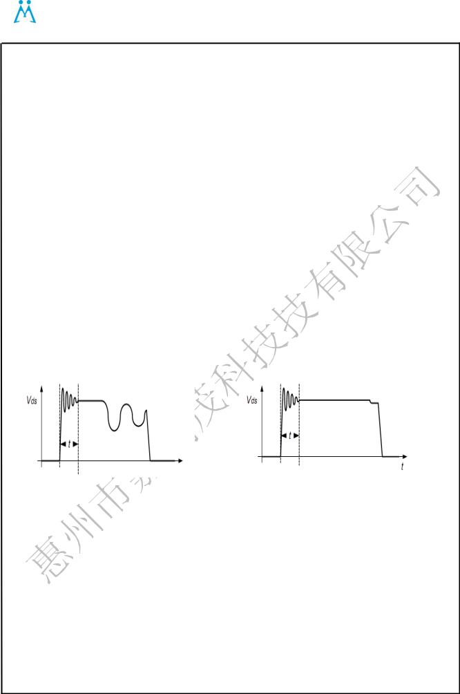
1.1.Vds t
1 t<2.5us |
2 t<1.5us |
Page 4 of 13

|
FILE NO. |
|
|
|
|
|
|
|
|
|
MODEL NO. |
PLE55-1A |
|
|
SPECIFICATION |
|
|
|
|
REVISION |
REV: 1.1 |
DATE |
2016-6-22 |
|
|
|
|
|
|
1.2. Output Characteristics
1.2.1.DC Output Characteristics
Item |
CH2 |
Condition |
|
|
|
|
|
Output Voltage |
12V |
RMS |
|
|
|||
|
|
||
|
|
|
|
Output Voltage range |
11.4-12.9 |
RMS |
|
|
|||
|
|
||
|
|
|
|
Minimum load current |
0.1A |
RMS |
|
|
|||
|
|
||
Rated load current |
1A |
RMS |
|
|
|||
|
|
||
Maxmum load current |
1.5A |
RMS |
|
|
|
|
|
Line regulation |
10.8-13.2 |
With rated load |
|
|
|||
|
|
||
|
|
|
|
DC Output Ripple & Noise |
≤220mV |
Min load to rated load |
|
(remark) |
|||
|
|
||
|
|
|
Remark: 1. Ripple and noise are defined as periodic or random signals over a frequency band of 10 Hz to
20MHz. 10 Hz 20MHz
2.Outputs should be bypassed at the connector with a 0.1uF ceramic disk capacitor and a 47uF electrolytic to simulate system loading. 0.1uF 47uF
1.2.1LED Backlight Characteristics
|
Item |
Parameter |
|
Symbol |
|
MIN |
TYP |
MAX |
|
Unit |
|||||
|
|
|
|
|
|
|
|
|
|
|
|
|
|
|
|
|
1 |
Input voltage |
|
Vin |
|
27 |
|
30 |
|
35 |
|
|
|
V |
|
|
|
|
|
|
|
|
|
|
|
|
|
|
|
|
|
|
2 |
Input current |
|
Iin |
|
--- |
|
0.933 |
--- |
|
|
|
A |
||
|
|
|
|
|
|
|
|
|
|
|
|
|
|
|
|
|
3 |
Input power |
|
Pin |
|
--- |
|
28 |
|
--- |
|
|
|
W |
|
|
|
|
|
|
|
|
|
|
|
|
|
|
|
|
|
|
4 |
Dimming Adjust |
|
PWM |
|
100 |
|
--- |
|
1000 |
|
|
|
Hz |
|
|
|
|
|
|
|
|
|
|
|
|
|
|
|
|
|
|
5 |
ADimming Adjust |
|
PWM |
|
10000 |
|
|
|
50000 |
|
|
|
Hz |
|
|
|
|
|
|
|
|
|
|
|
|
|
|
|
|
|
|
6 |
Open LED protection |
|
--- |
|
100 |
|
--- |
|
115 |
|
|
|
V |
|
|
|
|
|
|
|
|
|
|
|
|
|
|
|
|
|
|
7 |
Short LED protection |
|
|
|
|
|
|
YES |
|
|
|
|||
|
|
|
|
|
|
|
|
|
|
|
|
|
|
|
|
2. |
|
|
|
|
|
|
|
|
|
|
|
|
|
|
|
|
|
|
|
|
|
|
|
|
|
|
|
|
|||
|
Item |
parameter |
Test Conditions |
Symbol |
|
MIN |
|
TYP |
|
MAX |
|
Unit |
|||
|
|
|
|
|
|
|
|
|
|
|
|
|
|
||
|
1 |
Output voltage |
Maximun brightness |
|
Vout |
|
76.8 |
|
81.6 |
|
90 |
|
Vrms |
||
|
|
|
|
|
|
|
|
|
|
|
|
|
|
||
|
2 |
Output voltage |
brightness |
|
Iout |
|
285 |
|
300 |
|
315 |
|
mA |
||
|
|
|
|
|
|
|
|
|
|
|
|
|
|
||
|
3 |
Frequency |
Maximun brightness |
|
F |
|
|
|
105 |
|
|
|
kHz |
||
|
|
|
|
|
|
|
|
|
|
|
|
|
|
|
|
|
4 |
Adj Frequency |
|
DIM |
|
F |
|
|
|
200 |
|
|
|
Hz |
|
|
5 |
Dark start time |
Maximun brightness |
|
Ts |
|
1.0 |
|
--- |
|
20.0 |
|
mS |
||
|
|
|
|
|
|
|
|
|
|
|
|
|
|
|
|
Page 5 of 13

|
FILE NO. |
|
|
|
|
|
|
|
|
|
MODEL NO. |
PLE55-1A |
|
|
SPECIFICATION |
|
|
|
|
REVISION |
REV: 1.1 |
DATE |
2016-6-22 |
|
|
|
|
|
|
1.2.2. Backlight On / Off Control (Outside Signal Control )
Item |
|
BL_ON signal |
|
Condition |
|
Outputs Status |
|||
|
|
|
|
|
|||||
|
|
|
|
|
|
|
|
|
|
1 |
|
Active-high |
|
≥2.4V |
|
Enable |
|||
|
|
|
|
|
|||||
|
|
|
|
|
|
|
|
|
|
2 |
|
Active-low |
|
≤0.8V |
|
Unable |
|||
|
|
|
|
|
|||||
|
|
|
|
|
|
|
|
|
|
1.2.3. Output Overshoot At Turn On Turn Off |
|
|
|
||||||
|
|
|
|
|
|
|
|
|
|
|
Output (V) |
|
Over Shoot Voltage (Vmax.) Change Rate |
|
Condition |
|
|||
|
|
|
|
|
|
|
|||
|
|
Turn on |
|
Turn off |
|
||||
|
|
|
|
|
|
|
|
||
|
|
|
|
|
|
|
|
|
|
|
+12V |
|
≤10% |
|
≤10% |
|
Rated Load |
|
|
|
|
|
|
|
|
|
|
|
|
|
Remark: |
|
|
|
|
|
|
|
|
1.2.4. Turn-on Delay Time ,
Output voltage |
110Vac input |
220Vac input |
Condition |
|
|
|
|
+12V |
≤3000 ms |
≤2000 ms |
Rated Load |
|
|
|
|
1.2.5. Output Voltage Rise Time
Output voltage |
110Vac input |
220Vac input |
Condition |
|
|
|
|
+12V |
≤100ms |
≤100ms |
Rated Load |
|
|
|
|
Remark: The output voltages shall rise from 10% to 90% of their output voltage.
10 90
2. Protection
2.1. Input Protection
2.1.1 The input power line will be fused with a T3.15AH/250VAC fuse.
2.2. Over Voltage Protection
Output Voltage |
Over Voltage Range |
Over Voltage Protection Status |
Condition |
|
|
|
|
||
|
||||
|
|
|
|
|
+12V |
≤16V |
Lach |
Min Load |
|
|
|
|
|
Page 6 of 13

|
FILE NO. |
|
|
|
|
|
|
|
|
|
MODEL NO. |
PLE55-1A |
|
|
SPECIFICATION |
|
|
|
|
REVISION |
REV: 1.1 |
DATE |
2016-6-22 |
|
|
|
|
|
|
2.3. Short Circuit Protection
Output Voltage |
Short Circuit Protection Status |
|
|
|
|
+12V |
Hiccup |
|
|
Remark:
2.4. Over Current Protection
Output Voltage |
Over Current Protection |
|
|
|
|
+12V |
2A |
|
|
Remark:
3. Environmental Requirement
3.1. Temperature
Condition |
Minimum |
Maximum |
Unit |
|
|
|
|
Operating |
0 |
40 |
|
|
|
|
|
Storage |
-10 |
70 |
|
|
|
|
|
Temperature coefficient: ±0.04% per
3.2.Humidity
It is based on relative humidity and non-condensing.
Condition |
Minimum |
Maximum |
Unit |
|
|
|
|
Operating |
10% |
90% |
RH |
|
|
|
|
Storage |
5% |
95% |
RH |
|
|
|
|
3.3.Vibration and Shock
Vibration: 0.01G2 per Hz at 5Hz, sloping to 0.02G2 per Hz at 20Hz and maintaining 0.02G2 per Hz from 20Hz to 500Hz. The area under the PSD curve is 3.13gRMS. The duration shall be 10 minutes per axis for all three axes on all samples.
Shock: 50G Trapezoidal Wave, Velocity change = 170 in. / sec. Three drops in each of six
directions are applied to each of the samples.
Page 7 of 13

|
FILE NO. |
|
|
|
|
|
|
|
|
|
MODEL NO. |
PLE55-1A |
|
|
SPECIFICATION |
|
|
|
|
REVISION |
REV: 1.1 |
DATE |
2016-6-22 |
|
|
|
|
|
|
3.4. Altitude
Condition |
Minimum |
Maximum |
Unit |
|
|
|
|
Operating |
0 |
10000(3048) |
feet(m) |
|
|
|
|
Storage |
0 |
20000(6096) |
feet(m) |
|
|
|
|
3.5.Cooling Method
Ventilation Cooling.
3.5. RoHS EU
Compliance with standard of RoHS (EU), apply for mass production.
4. Safety & EMC
4.1. Safety Requirements
Safety |
Standard |
|
|
CUL |
UL60065/EN60065 |
|
|
TUV / GS |
|
|
|
Nemko |
|
|
|
Demko |
|
|
|
Fimko |
|
|
|
Semko |
|
|
|
PSE |
|
|
|
CB |
|
|
|
CCC |
GB8898-2011 |
|
|
4.2. EMS
Test item |
Test Specification |
IEC Standard |
|
|
|
||
|
|||
|
|
|
|
ESD |
Contact 8 KV |
61000-4-2 |
|
|
|
|
|
ESD |
Air 15 KV, Contact 8KV |
61000-4-2 |
|
|
|
|
|
RS |
FR : 26 MHz ~ 1 GHz, Field / Strength : 3 V / M |
61000-4-3 |
|
|
|
|
|
EFT |
2 KV on AC power line |
61000-4-4 |
|
|
|
|
|
SURGE |
2KV (L – N ) & 4 KV (L/N – PE ) / 1.2 ~ 50Usec |
61000-4-5 |
|
. TCL standard: Common mode:6kV,different mode:2kV |
|||
|
|
||
CS |
3 V / M |
61000-4-6 |
|
|
|
|
|
DIPS |
0 % 250 Cy. / 40% 5 Cy. / 70% 5 Cy. |
61000-4-11 |
|
|
|
|
Page 8 of 13

|
FILE NO. |
|
|
|
|
|
|
|
|
|
MODEL NO. |
PLE55-1A |
|
|
SPECIFICATION |
|
|
|
|
REVISION |
REV: 1.1 |
DATE |
2016-6-22 |
|
|
|
|
|
|
4.3.Conducted EMI
This requirement should be acquired as whole system.
4.4.Radiated EMI and EMC
This requirement should be acquired as whole system.
4.5.Dielectric Withstand Hi Pot Test
|
Primary to Secondary |
3000 Vac or 4242 Vdc Hi-Pot |
|
|
Test from primary to secondary |
Trip current <10mA, 50Hz |
|
|
|
||
|
for a minimum of one minute |
|
|
|
|
|
|
|
|
|
|
4.6. Insulation |
|
|
|
|
|
|
|
|
Input To Output |
Insulated Resistance |
Test Condition |
|
|
|
|
|
|
≥ 6M OHM |
DC 500V |
|
|
||
|
|
|
|
5. Reliabilities
Item |
Description |
|
|
M.T.B.F. |
MTBF of PSU shall equal or exceed 30,000 hours when operated at 75% |
|
continuous load in an ambient temperature of 25 as calculated by parts |
|
stress method of MIL-HDBK-217F. |
Temperature rise |
|
|
Refer to set system’s requirement & standard. |
|
|
Surge and EFT |
|
|
Refer to set system’s requirement & standard. |
|
|
Burn-in |
|
|
Refer to set system’s requirement & standard. 80% |
|
|
Derating test |
|
|
Refer to set system’s requirement & standard. |
|
|
Abnormal test |
Damage to the device must not occur such as fire and molten metal |
|
phenomena. |
|
|
Page 9 of 13

|
FILE NO. |
|
|
|
|
|
|
|
|
|
MODEL NO. |
PLE55-1A |
|
|
SPECIFICATION |
|
|
|
|
REVISION |
REV: 1.1 |
DATE |
2016-6-22 |
|
|
|
|
|
|
6. Acoustics
Refer to set system’s requirement and standard with acoustic noise.
7. Mechanicals
7.1. PCB Dimension: 150mm(L) * 100mm(W) * 14.5mm(H))
7.2. Dimension with soleplate: NONE
8.WEIGHT
9.Pin Connection
2PIN-CN401 pitch 8.4mm Connection and Function
Item |
|
Pin Connection |
|
Function |
|
|
|
|
|
1 |
|
AC-L |
|
AC INPUT LINE |
|
|
|
|
|
2 |
|
AC-N |
|
AC INPUT NUTURE |
|
|
|
||
7*2pin-P2:pitch 2.0mm Connection and Function |
|
|||
|
|
|
|
|
Item |
|
Pin Connection |
|
Function |
1,3,4,5,6 |
|
+12V |
|
+12V OUTPUT |
|
|
|
||
7,8,11 |
|
GND |
|
RETURN |
|
|
|
||
9 |
|
NC |
|
NC |
|
|
|
||
10 |
|
ADIM |
|
ANALOG SIGNAL INPUT |
|
|
|
||
12 |
|
NC |
|
NC |
|
|
|
||
13 |
|
DIM |
|
PWM SIGNAL INPUT |
|
|
|
||
14 |
|
BL-ON |
|
BL/ON CONTROL |
|
|
|
||
10pin-P1: 2.0mm Connection and Function |
|
|||
|
|
|
|
|
Item |
|
Pin Connection |
|
Function |
1,2,9,10 |
|
VLED |
|
+LED INPUT |
|
|
|
||
3,8 |
|
|
|
NC |
|
|
|
|
|
4,5,6,7 |
|
Cathode of LED String |
|
-LED Current Output |
|
|
|
||
Page 10 of 13
 Loading...