


AIR TO WATER HEAT PUMP
Installation manual
Outdoor Unit
Model name:
HWS-802H-E
HWS-1102H-E
HWS-1402H-E
Installation manual |
|
English |
Air to Water Heat Pump |
2 |
|
|
|
|
Manuel d’installation |
|
|
|
Français |
|
Pompe à chaleur air/eau |
24 |
|
|
|
|
Installations-handbuch |
|
|
|
Deutsch |
|
Luft-/Wasserwärmepumpe |
46 |
|
|
|
|
Installationshandbok |
|
|
|
Svenska |
|
Luft-till-vatten-värmepump |
68 |
|
|
|
|

Air to Water Heat Pump |
Outdoor Unit Installation Manual |
Please read this Installation Manual carefully before installing the Air to Water Heat Pump.
•This Manual describes the installation method of the outdoor unit.
•For installation of the hydro unit, follow the Installation Manual attached to the hydro unit.
ADOPTION OF NEW REFRIGERANT
This Air to Water Heat Pump is a new type which adopts a new refrigerant HFC (R410A) instead of the conventional refrigerant R22 in order to prevent destruction of the ozone layer.
Contents |
|
|
1 |
ACCESSORY PARTS AND REFRIGERANT . . . . . . . . . . . . . . . . . . . . . . . . . . . . . . . |
. 3 |
2 |
PRECAUTIONS FOR SAFETY . . . . . . . . . . . . . . . . . . . . . . . . . . . . . . . . . . . . . . . . . . |
. 4 |
3 |
INSTALLATION OF NEW REFRIGERANT AIR TO WATER HEAT PUMP . . . . . . . . . |
5 |
4 |
SELECTION OF INSTALLATION . . . . . . . . . . . . . . . . . . . . . . . . . . . . . . . . . . . . . . . . . |
7 |
5 |
REFRIGERANT PIPING . . . . . . . . . . . . . . . . . . . . . . . . . . . . . . . . . . . . . . . . . . . . . . . . |
12 |
6 |
AIR PURGING . . . . . . . . . . . . . . . . . . . . . . . . . . . . . . . . . . . . . . . . . . . . . . . . . . . . . . . |
15 |
7 |
ELECTRICAL WORK . . . . . . . . . . . . . . . . . . . . . . . . . . . . . . . . . . . . . . . . . . . . . . . . . . |
17 |
8 |
EARTHING . . . . . . . . . . . . . . . . . . . . . . . . . . . . . . . . . . . . . . . . . . . . . . . . . . . . . . . . . . |
19 |
9 |
FINISHING . . . . . . . . . . . . . . . . . . . . . . . . . . . . . . . . . . . . . . . . . . . . . . . . . . . . . . . . . . |
19 |
10 TEST RUN . . . . . . . . . . . . . . . . . . . . . . . . . . . . . . . . . . . . . . . . . . . . . . . . . . . . . . . . . . |
19 |
|
11 ANNUAL MAINTENANCE . . . . . . . . . . . . . . . . . . . . . . . . . . . . . . . . . . . . . . . . . . . . . . |
19 |
|
12 FUNCTIONS TO BE IMPLEMENTED LOCALLY . . . . . . . . . . . . . . . . . . . . . . . . . . . . |
20 |
|
13 TROUBLESHOOTING . . . . . . . . . . . . . . . . . . . . . . . . . . . . . . . . . . . . . . . . . . . . . . . . . |
21 |
|
14 APPENDIX . . . . . . . . . . . . . . . . . . . . . . . . . . . . . . . . . . . . . . . . . . . . . . . . . . . . . . . . . . |
22 |
|
1-EN |
– 2 – |

Air to Water Heat Pump |
Outdoor Unit Installation Manual |
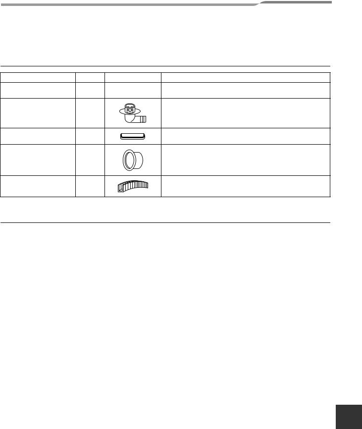
1 ACCESSORY PARTS AND REFRIGERANT
Accessory parts
Part name |
Q’ty |
Shape |
Usage |
|
Outdoor unit |
1 |
This manual |
(Hand this directly to the customer.) |
|
Installation manual |
||||
|
|
|
||
Drain nipple |
1 |
|
|
|
Waterproof rubber cap |
5 |
|
|
|
Protective bush |
1 |
|
For protecting wires (pipe cover) |
|
Guard material for passage |
1 |
|
For protecting passage part (pipe cover) |
|
part |
|
|||
|
|
|
Refrigerant Piping
•Piping kit used for the conventional refrigerant cannot be used.
•Use copper pipe with 0.8 mm or more thickness for Ø9.5 mm. Use copper pipe with 1.0 mm or more thickness for Ø15.9 mm.
•Flare nut and flare works are also different from those of the conventional refrigerant. Take out the flare nut attached to the Air to Water Heat Pump, and use it.
EN
– 3 – |
2-EN |

Air to Water Heat Pump |
Outdoor Unit Installation Manual |
2 PRECAUTIONS FOR SAFETY
•Ensure that all Local, National and International regulations are satisfied.
•Read this “PRECAUTIONS FOR SAFETY” carefully before Installation.
•The precautions described below include the important items regarding safety. Observe them without fail.
•After the installation work, perform a trial operation to check for any problem.
Follow the Owner’s Manual to explain how to use and maintain the unit to the customer.
•Turn off the main power supply switch (or breaker) before the unit maintenance.
•Ask the customer to keep the Installation Manual together with the Owner’s Manual.
 WARNING
•Ask an authorized dealer or qualified installation professional to install/maintain the Air to Water Heat Pump.
Inappropriate installation may result in water leakage, electric shock or fire.
•Be sure to connect earth wire. (grounding work)
Incomplete grounding cause an electric shock.
Do not connect ground wires to gas pipes, water pipes, lightning rods or ground wires for telephone wires.
•Turn off the main power supply switch or breaker before attempting any electrical work.
Make sure all power switches are off. Failure to do so may cause electric shock.
Use an exclusive power circuit for the Air to Water Heat Pump. Use the rated voltage.
•Connect the connecting wire correctly.
If the connecting wire is connected in a wrong way, electric parts may be damaged.
•When moving the Air to Water Heat Pump for the installation into another place, be very careful not to enter any gaseous matter other than the specified refrigerant into the refrigeration cycle.
If air or any other gas is mixed in the refrigerant, the gas pressure in the refrigeration cycle becomes abnormally high and it may resultingly causes pipe burst and injuries on persons.
•Do not modify this unit by removing any of the safety guards or by by-passing any of the safety interlock switches.
•After unpacking the unit, examine it carefully if there are possible damage.
•Do not install in a place that might increase the vibration of the unit.
•To avoid personal injury (with sharp edges), be careful when handling parts.
•Perform installation work properly according to the Installation Manual.
Inappropriate installation may result in water leakage, electric shock or fire.
•When the Air to Water Heat Pump hydro unit is installed in a small room, provide appropriate measures to ensure that the concentration of refrigerant leakage occur in the room does not exceed the critical level.
•Tighten the flare nut with a torque wrench in the specified manner.
Excessive tightening of the flare nut may cause a crack in the flare nut after a long period, which may result in refrigerant leakage.
•Wear heavy gloves during the installation work to avoid injury.
•Install the Air to Water Heat Pump securely in a location where the base can sustain the weight adequately.
•Perform the specified installation work to guard against an earthquake.
If the Air to Water Heat Pump is not installed appropriately, accidents may occur due to the falling unit.
•If refrigerant gas has leaked during the installation work, ventilate the room immediately.
If the leaked refrigerant gas comes in contact with fire, noxious gas may generate.
•After the installation work, confirm that refrigerant gas does not leak.
If refrigerant gas leaks into the room and flows near a fire source, such as a cooking range, noxious gas might generate.
•Electrical work must be performed by a qualified electrician in accordance with the Installation Manual. Make sure the Air to Water Heat Pump uses an exclusive power supply.
An insufficient power supply capacity or inappropriate installation may cause fire.
•Use the specified wires for wiring connect the terminals securely fix.
To prevent external forces applied to the terminals from affecting the terminals.
3-EN |
– 4 – |

Air to Water Heat Pump |
Outdoor Unit Installation Manual |
 WARNING
•When the Air to Water Heat Pump cannot cool or heat water well, contact the dealer from whom you purchased the Air to Water Heat Pump as refrigerant leakage is considered as the cause.
In the case of repair that requires refill of refrigerant, ask service personnel about details of the repair.
The refrigerant used in the Air to Water Heat Pump is harmless.
Generally, the refrigerant does not leak. However, if the refrigerant leaks in a room and a heater or stove burner in the room catches fire, it may generate toxic gas.
When you ask service personnel for repairing refrigerant leakage, confirm that the leakage portion has been completely repaired.
•Conform to the regulations of the local electric company when wiring the power supply.
Inappropriate grounding may cause electric shock.
•Do not install the Air to Water Heat Pump in a location subject to a risk of exposure to a combustible gas.
If a combustible gas leaks, and stays around the unit, a fire may occur.
•Install the refrigerant pipe securely during the installation work before operating the Air to Water Heat Pump.
If the compressor is operated with the valve open and without the refrigerant pipe, the compressor sucks air and the refrigeration cycle is overpressurized, which may cause a burst or injury.
•For the refrigerant recovery work (collection of refrigerant from the pipe to the compressor), stop the compressor before disconnecting the refrigerant pipe.
If the refrigerant pipe is disconnected while the compressor is working with the valve open, the compressor sucks air and the refrigeration cycle is overpressurized, which may cause a burst or injury.
 CAUTION
New Refrigerant Air to Water Heat Pump Installation
•THIS AIR TO WATER HEAT PUMP ADOPTS THE NEW HFC REFRIGERANT (R410A) WHICH DOES NOT DESTROY OZONE LAYER.
•The characteristics of R410A refrigerant are ; easy to absorb water, oxidizing membrane or oil, and its pressure is approx. 1.6 times higher than that of refrigerant R22. Accompanied with the new refrigerant, refrigerating oil has also been changed. Therefore, during installation work, be sure that water, dust, former refrigerant, or refrigerating oil does not enter the refrigerating cycle.
•To prevent charging an incorrect refrigerant and refrigerating oil, the sizes of connecting sections of charging port of the main unit and installation tools are changed from those for the conventional refrigerant.
•Accordingly the exclusive tools are required for the new refrigerant (R410A).
•For connecting pipes, use new and clean piping designed for R410A, and please care so that water or dust does not enter.
To Disconnect the Appliance from Main Power Supply
•This appliance must be connected to the main power supply by means of a switch with a contact separation of at least 3 mm.
•The installation fuse 25 A (All type fuse can be used) must be used for the power supply line of this unit.
3 INSTALLATION OF NEW REFRIGERANT
AIR TO WATER HEAT PUMP |
EN |
|
•The R410A refrigerant is more susceptible to impurities such as water, oxide membrane, oils, and fats. With the adoption of the new refrigerant, refrigerating oil has also been changed.
Be careful so that water, dust, conventional refrigerant, and/or conventional refrigerating oil do not enter the refrigerating cycle of the new refrigerant Air to Water Heat Pump.
•To prevent different refrigerant or refrigerating oil being mixed, the sizes of the charging port of the unit and the installation tool connecting sections are different from the conventional refrigerant. Accordingly the following exclusive tools are required for the new refrigerant R410A.
– 5 – |
4-EN |

Air to Water Heat Pump |
Outdoor Unit Installation Manual |
Required Tools/Equipment and Precautions for Use
Prepare the tools and equipment listed in the following table before starting installation work. Newly prepared tools and equipment must be used exclusively.
Legend
 : Prepared newly (Use for R410A only. Do not use for refrigerant R22 or R407C etc..)
  : Conventional tools/equipment are available
Tools/equipment |
Use |
How to use tools/equipment |
|
|
|
|
|
Gauge manifold |
Vacuuming/charging |
Prepared newly for R410A only |
|
|
refrigerant and operation |
|
|
Charging hose |
Prepared newly for R410A only |
||
check |
|||
|
|
|
|
Charging cylinder |
Can not be used |
Unusable (Use the refrigerant charging measure instead.) |
|
|
|
|
|
Gas leak detector |
Gas leak check |
Prepared newly |
|
|
|
|
|
Vacuum pump with backflow |
Vacuum drying |
Unusable |
|
prevention function |
|||
|
|
||
Vacuum pump with backflow |
Vacuum drying |
R22 (Conventional tools) |
|
prevention function |
|||
|
|
||
Flare tool |
Flare machining of pipes |
Usable if dimensions are adjusted. |
|
|
|
|
|
Bender |
Bending pipes |
R22 (Conventional tools) |
|
|
|
|
|
Refrigerant recovery equipment |
Refrigerant recovery |
For R410A only |
|
|
|
|
|
Torque wrench |
Tightening flare nuts |
Exclusive for Ø12.7 mm and Ø15.9 mm |
|
|
|
|
|
Pipe cutter |
Cutting pipes |
R22 (Conventional tools) |
|
|
|
|
|
Refrigerant cylinder |
Charging refrigerant |
For R410A only |
|
Discriminated by the refrigerant name on the cylinder. |
|||
|
|
||
|
|
|
|
Welding machine and nitrogen |
Welding pipes |
R22 (Conventional tools) |
|
cylinder |
|||
|
|
||
Refrigerant charging measure |
Charging refrigerant |
R22 (Conventional tools) |
|
|
|
|
Refrigerant Piping
New refrigerant (R410A)
When using the conventional piping kit
•When using the conventional piping kit that has no indication of applicable refrigerant types, be sure to use it with a wall thickness of 0.8 mm for Ø6.4 mm, Ø9.5 mm, and Ø12.7 mm, and with a wall thickness of 1.0 mm for Ø15.9 mm. Never use the conventional piping kit with a wall thickness less than these thicknesses due to insufficient pressure capacity.
When using general copper pipes
•Use general copper pipes with a wall thickness of 0.8 mm for Ø6.4 mm, Ø9.5 mm, and Ø12.7 mm, and with a wall thickness of 1.0 mm for Ø15.9 mm.
Never use any copper pipes with a wall thickness less than these thicknesses.
Flare nuts and flare machining
•The flare nuts and flare machining are different from those for the conventional refrigerant. Use the flare nuts supplied with the Air to Water Heat Pump or those for R410A.
•Before performing flare machining, carefully read “REFRIGERANT PIPING”
5-EN |
– 6 – |
Air to Water Heat Pump |
Outdoor Unit Installation Manual |
4 SELECTION OF INSTALLATION
Before installation
Be careful to the following items before installation.
Length of refrigerant pipe
Length of refrigerant
pipe connected to hydro/ Item outdoor unit
3 m to 30 m |
Addition of refrigerant is |
|
unnecessary at the local site. |
||
|
*Do not connect a refrigerant pipe shorter than 3 m. This may cause a malfunction of the compressor or other devices.
Airtight test
1.Before starting an airtight test, further tighten the spindle valves on the gas side and liquid side.
2.Pressurize the pipe with nitrogen gas charged from the service port to the design pressure (4.15 Mpa) to conduct the airtight test.
3.After the airtight test is completed, evacuate the nitrogen gas.
Air purge
•For air purge, use a vacuum pump.
•Do not use refrigerant charged in the outdoor unit for air purge. (The refrigerant for air purge is not contained in the outdoor unit.)
Electrical wiring
Be sure to fix the power wires and hydro/outdoor connecting wires with clamps so that they do not contact with the cabinet, etc.
Earthing
 WARNING
Make sure that proper earthing is provided.
Improper earthing may cause electric shock. For how to check earthing, contact the dealer who installed the Air to Water Heat Pump or a professional installation company.
•Proper earthing can prevent charging of electricity on the outdoor unit surface due to high frequency of the frequency converter (inverter) in the outdoor unit, as well as prevent electric shock. If the outdoor unit is not properly earthed, you may feel electric shock.
•Be sure to connect earth wire. (grounding work)
Incomplete grounding cause an electric shock. Do not connect ground wires to gas pipes, water pipes, lightning rods or ground wires for telephone wires.
Test Run
•Start test run when the water piping work is completed and the system is filled with the proper amount of water.
•Turn on the leakage breaker at least 12 hours before starting a test run to protect the compressor during startup.
 CAUTION
Incorrect work may result in a malfunction or complaints of customers.
EN
– 7 – |
6-EN |

Air to Water Heat Pump |
Outdoor Unit Installation Manual |
Installation Place
 WARNING
Install the outdoor unit properly at a place that is durable enough to the weight of the outdoor unit.
Insufficient durability may cause the outdoor unit to fall, which may result in injury.
 CAUTION
Do not install the outdoor unit at a place subject to combustible gas leak.
Accumulation of combustible gas around the outdoor unit may cause a fire.
Install the outdoor unit at a place that meets the following conditions after customer’s consent is obtained.
•A well-ventilated place free from obstacles near the air inlets and air outlet
•A place that is not exposed to rain or direct sunlight
•A place that does not increase the operating noise or vibration of the outdoor unit
•A place that does not cause any drainage problem with discharged water
Do not install the outdoor unit at the following places.
•A place full of saline atmosphere (coastal area) or sulfide gas (hot-spring area)
(Special maintenance is required.)
•A place subject to oil, vapor, oily smoke, or corrosive gas
•A place where organic solvent is used
•A place where high-frequency equipment (including inverter equipment, private power generator, medical equipment, and communication equipment) is used
(Installation in this place may cause malfunction of the Air to Water Heat Pump, abnormal control or problems due to noise to such equipment.)
•A place where the discharged air of the outdoor unit blows against the window of the neighboring house
•A place where the operating noise of the outdoor unit is transmitted
•When the outdoor unit is installed in an elevated position, be sure to secure its feet.
•A place where the drain water does not make any problem.
 CAUTION
1.Install the outdoor unit at a place where discharge air is not blocked.
2.When an outdoor unit is installed in a place that is always exposed to a strong wind like a coast or on a high storey of a building, secure a normal fan operation by using a duct or a wind shield.
3.When installing the outdoor unit in a place that is constantly exposed to a strong wind such as the upper stairs or rooftop of a building, apply the windproof measures referring to the following examples.
1)Install the unit so that its discharge port faces to the wall of the building.
Keep a distance 500 mm or more between the unit and the wall surface.
500
2)Supposing the wind direction during the operation season of the Air to Water Heat Pump, install the unit so that the discharge port is set at right angle to the wind direction.
Strong Strong wind wind
•When using an Air to Water Heat Pump under low outside temperature condition (Outside temp.:-5 °C or lower) with COOL mode, prepare a duct or wind shield so that it is not affected by the wind.
<Example>
Wind shield |
Wind shield |
Wind shield
7-EN |
– 8 – |
Air to Water Heat Pump |
Outdoor Unit Installation Manual |
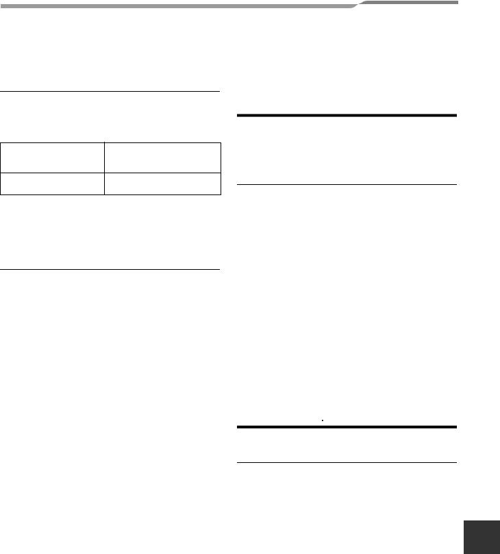
Necessary Space for Installation |
(Unit:mm) |
||
Obstacle at rear side |
|
Obstacle at front side |
|
▼ Upper side is free |
|
▼ Upper side is free |
|
1. Single unit installation |
|
1. Single unit installation |
|
|
150 or more |
|
500 or more |
2. Obstacles at both right and left sides |
2. Serial installation of two or more units |
||
200 more |
The height of the |
|
|
or |
obstacle should be |
|
|
|
lower than the height |
|
|
|
of the outdoor unit. |
|
1000 ormore |
150 |
300 |
|
|
or more |
or more |
|
|
3. Serial installation of two or more units
|
|
|
200 or more |
150 |
300 |
300 |
300 |
or more |
or more |
or more |
or more |
The height of the obstacle should be lower than the height of the outdoor unit.
▼ Obstacle also at the upper side
500 more |
150 |
or more |
|
or |
|
▼ Obstacle also at the upper side
1000 |
1000 moreor |
or more |
|
Obstacles at both front and rear sides
Open the upper side and both right and left sides. The height of obstacle at both front and rear side, should be lower than the height of the outdoor unit.
▼ Standard installation
1. Single unit installation
1000 150 or more or more
EN
– 9 – |
8-EN |
Air to Water Heat Pump |
Outdoor Unit Installation Manual |
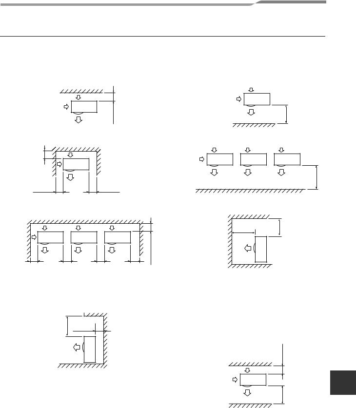
2. Serial installation of two or more units
|
|
200 more |
|
|
or |
300 |
300 |
1000 moreor |
or more |
or more |
|
Serial installation at front and rear sides
Open the upper side and both right and left sides. The height of obstacle at both front and rear sides should be lower than the height of the outdoor unit.
▼ Standard installation
|
|
|
|
|
|
|
|
|
|
|
|
|
|
|
|
|
|
|
|
|
|
|
|
|
|
|
|
|
|
|
|
|
|
|
|
|
|
|
|
|
|
|
|
|
|
|
|
|
|
|
|
|
|
|
|
|
1000 |
|
300 |
|
1500 |
|
2000 |
|
200 |
|
|||||||||
or more |
or more |
|
or more |
|
|
or more |
or more |
|||||||||||
Installation of Outdoor Unit
•Before installation, check strength and horizontality of the base so that abnormal sound does not generate.
•According to the following base diagram, fix the base firmly with the anchor bolts.
(Anchor bolt, nut: M10 x 4 pairs)
Drain hole
150 |
525 |
|
600 |
150 |
|
|
45 |
|
400 |
365 |
Drain
nipple mounting hole
Drain hole
•As shown in the figure below, install the foundation and vibration-proof rubbers to directly support the bottom surface of the fixing leg that is in contact with the bottom plate of the outdoor unit.
*When installing the foundation for an outdoor unit with downward piping, consider the piping work.
|
GOOD |
|
Absorb vibration |
Fixing leg |
with vibration- |
proof rubbers |
|
Foundation |
|
|
GOOD |
|
Bottom plate |
|
of outdoor unit |
Foundation
Support the bottom surface of the fixing leg in contact with the bottom plate of the outdoor unit.
If only the end of the fixing leg is supported, it may be deformed. 
Foundation 

NO GOOD |
|
Do not support |
||||
|
|
|
the outdoor unit |
|||
|
|
|
only with the |
|||
|
|
|
fixing leg. |
|||
|
|
|
|
|
|
|
|
|
|
|
|
|
|
|
|
|
|
|
|
|
Set the out margin of the anchor bolt to 15 mm or less.
15 or less
9-EN |
– 10 – |
Air to Water Heat Pump
•In case of draining through the drain hose, attach the following drain nipple and the waterproof rubber cap, and use the drain hose (Inner diam.: 16 mm) sold on the market. And also seal the screws securely with silicone material, etc. so that water does not drop down. Some conditions may cause dewing or dripping of water.
•When collectively draining discharged water completely, a drain pan must be made locally.
Drain nipple |
Waterproof rubber cap |
(5pcs.) |
Drain nipple
Waterproof rubber cap
For Reference
If a heating operation would be continuously performed for a long time under the condition that the outdoor temperature is 0 °C or lower, draining of defrosted water may be difficult due to freezing of the bottom plate, resulting in a trouble of the cabinet or fan.
It is recommended to procure an anti-freeze heater locally for a safety installation of the Air to Water Heat Pump.
For details, contact the dealer.
Outdoor Unit Installation Manual
EN
– 11 – |
10-EN |

Air to Water Heat Pump |
Outdoor Unit Installation Manual |
5 REFRIGERANT PIPING
Knockout of Pipe Cover
Rear direction
Pipe cover
 Side direction
Front direction
Down direction
Knockout procedure
•The hydro/outdoor connecting pipes can be connected to 4 directions.
Take off the knockout part of the pipe cover in which pipes or wires pass through the base plate.
•Detach the piping cover and give an impact on the knockout section a few times with the shank of a screwdriver. A knockout hole can easily be punched.
•After punching the knockout hole, remove burrs of the hole and then install the supplied protective bush and guard material for passage part to protect wires and pipes.
Be sure to attach the pipe covers after pipes have been connected. Cut the slits under the pipe covers to facilitate the installation.
After connecting the pipes, be sure to mount the pipe cover. The pipe cover is easily mounted by cutting off the slit at the lower part of the pipe cover.
* Be sure to wear heavy work gloves while working.
Supplied protective bush
Supplied passage hole guard material
* Attach the guard material securely so that it does not come loose.
Optional Installation Parts
(Local Procure)
|
Parts name |
Q’ty |
|
|
|
|
Refrigerant piping |
|
A |
Liquid side : Ø9.5 mm |
Each one |
|
Gas side : Ø15.9 mm |
|
B |
Pipe insulating material |
1 |
(polyethylene foam, 10 mm thick) |
||
|
|
|
C |
Putty, PVC tapes |
Each one |
|
|
|
Refrigerant Piping
Connection
 CAUTION
TAKE NOTICE THESE IMPORTANT
4 POINTS BELOW FOR PIPING WORK
1.Keep dust and moisture away from inside the connecting pipes.
2.Tightly connect the connection between pipes and the unit.
3.Evacuate the air in the connecting pipes using VACUUM PUMP.
4.Check gas leak at connected points.
▼Piping connection
Liquid side |
Gas side |
|||
|
|
|
|
|
Outer |
Thickness |
Outer |
Thickness |
|
diameter |
diameter |
|||
|
|
|||
Ø9.5 mm |
0.8 mm |
Ø15.9 mm |
1.0 mm |
|
|
|
|
|
|
11-EN |
– 12 – |

Air to Water Heat Pump |
Outdoor Unit Installation Manual |
Flaring
1.Cut the pipe with a pipe cutter.
Be sure to remove burrs that may cause gas leak.
2.Insert a flare nut into the pipe, and then flare the pipe.
Use the flare nuts supplied with the Air to Water Heat Pump or those for R410A.
Insert a flare nut into the pipe, and flare the pipe.
As the flaring sizes of R410A differ from those of refrigerant R22, the flare tools newly manufactured for R410A are recommended.
However, the conventional tools |
B |
can be used by adjusting |
|
projection margin of the copper |
|
pipe. |
|
▼ Projection margin in flaring : B (Unit : mm)
Rigid (Clutch type)
Outer diam. of |
R410A tool used |
Conventional |
tool used |
||
copper pipe |
|
|
R410A |
|
|
|
|
|
|
|
|
9.5 |
0 to 0.5 |
1.0 to 1.5 |
|
|
|
15.9 |
|
|
|
|
|
|
|
|
▼ Flare nut width: H and flare matching size: A.
Flare nut width: H
|
|
|
|
|
|
|
(mm) |
|
|
|
|
|
|
|
|
|
|
Copper pipe |
Ø6.4 |
Ø9.5 |
Ø12.7 |
Ø15.9 |
Ø19.0 |
|
|
outer diam. |
|||||
|
|
|
|
|
|
|
|
H |
For R410A |
17 |
22 |
26 |
29 |
36 |
|
|
|
|
|
|
|
|
|
Flare machining size: A
A |
|
|
|
A +0, -0.4 |
|
(mm) |
|||
|
|
|
|||||||
|
|
|
|
Copper pipe |
Ø6.4 |
Ø9.5 |
Ø12.7 |
Ø15.9 |
Ø19.0 |
|
|
|
|
||||||
|
|
|
|
outer diam. |
|||||
|
|
|
|
|
|
|
|
|
|
|
|
|
|
|
|
|
|
|
|
|
|
|
|
For R410A |
9.1 |
13.2 |
16.6 |
19.7 |
24.0 |
|
|
|
|
|
|
|
|
|
|
Do not apply the refrigerator oil to the flare surface.
* In case of flaring for R410A with the |
|
|
A |
|
|
conventional flare tool, pull it out approx. |
|
|
|
|
|
|
|
|
|
||
0.5 mm more than that for R22 to adjust |
|
|
|
|
|
|
|
|
|
||
to the specified flare size. |
|
|
|
|
|
The copper pipe gauge is useful for |
|
|
|
|
|
adjusting projection margin size. |
|
|
|
|
|
Tightening of Connecting Part
1.Align the centers of the connecting pipes and fully tighten the flare nut with fingers. Then fix the nut with a spanner as shown in the figure and tighten it with a torque wrench.
2.As shown in the figure, be sure to use two spanners to loosen or tighten the flare nut of the valve on the gas side. If you use a single spanner, the flare nut cannot be tightened to the required tightening torque.
On the other hand, use a single spanner to loosen or tighten the flare nut of the valve on the liquid side.
|
(Unit: N•m) |
Outer diam. of copper pipe |
Tightening torque |
9.5 mm (diam.) |
33 to 42 (3.3 to 4.2 kgf•m) |
15.9 mm (diam.) |
68 to 82 (6.8 to 8.2 kgf•m) |
Half union or packed valve |
Flare nut |
Externally |
Internally |
threaded side |
threaded side |
Fix with spanner. |
Tighten with torque wrench. |
|
Cover |
Cap
Piping valve
Loosened
Tightened
Flare nut
Valve at gas side
EN
– 13 – |
12-EN |

Air to Water Heat Pump |
Outdoor Unit Installation Manual |
 CAUTION
1.Do not put the spanner on the cap or cover.
The valve may be broken.
2.If applying excessive torque, the nut may be broken according to some installation conditions.
•After the installation work, be sure to check gas leak of connecting part of the pipes with nitrogen.
NO GOOD
Cover
Cap
Refrigerant Pipe Length
Refrigeration pipe
H: max. ±30 m (above/below)
L: max. 30 m, min. 3 m
Hydro Unit
Outdoor unit
H
L
30 m chargeless
•Pressure of R410A is higher than that of R22 (Approx. 1.6 times).
Therefore, using a torque wrench, tighten the flare pipe connecting sections which connect the hydro/ outdoor units at the specified tightening torque.
Incomplete connections may cause not only a gas leak, but also a trouble of the refrigeration cycle.
Do not apply refrigerating machine oil to the flared surface.
13-EN |
– 14 – |

Air to Water Heat Pump |
Outdoor Unit Installation Manual |
6 AIR PURGING
Airtight test
Before starting an airtight test, further tighten the spindle valves on the gas side and liquid side.
Pressurize the pipe with nitrogen gas charged from the service port to the design pressure (4.15 Mpa) to conduct the airtight test.
After the airtight test is completed, evacuate the nitrogen gas.
Air Purge
With respect to the preservation of terrestrial environment, adopt “Vacuum pump” for air purge (Evacuate air in the connecting pipes) when installing the unit.
•Do not discharge the refrigerant gas to the atmosphere to preserve the terrestrial environment.
•Use a vacuum pump to discharge the air (nitrogen, etc.) remained in the set. If the air remains, the capacity may decrease.
For the vacuum pump, be sure to use one with backflow preventer so that the oil in the pump does not backflow into the pipe of the Air to Water Heat Pump when the pump stops.
(If oil in the vacuum pump is put in an Air to Water Heat Pump including R410A, it may cause trouble on the refrigeration cycle.)
Vacuum pump
As shown in the figure, connect the charge hose after the manifold valve are closed completely.
È
Attach the connecting port of the charge hose with a projection to push the valve core (setting pin) to the charge port of the set.
È
Open handle Low fully.
È
Turn ON the vacuum pump (*1)
È
Loosen the flare nut of the packed valve (Gas side) a little to check the air passes through. (*2)
È
Tighten the flare nut again.
È
Execute vacuuming until the compound pressure gauge indicates – 101kPa (–76cmHg). (*1)
È
Close handle Low completely.
È
Turn OFF the vacuum pump.
È
Leave the vacuum pump as it is for 1 or 2 minutes, and check the indicator of the compound pressure gauge does not return.
È
Open fully the valve stem or the valve handle. (First, at liquid side, then gas side)
È
(continued) |
È |
Disconnect the charge hose from the charge port.
È
Tighten valve and caps of the charge port surely.
*1 Use the vacuum pump, vacuum pump adapter, and gauge manifold correctly referring to the manuals supplied with each tool before using them.
Check that the vacuum pump oil is filled up to the specified line of the oil gauge.
*2 When air is not charged, check again whether the connecting port of the discharge hose, which has a projection to push the valve core, is firmly connected to the charge port.
Compound pressure gauge |
Pressure gauge |
|
|
–101 kPa |
|
Gauge manifold |
|
(–76 cmHg) |
|
valve |
|
Handle Lo |
Handle Hi |
EN |
|
|
|
(Keep fully |
|
Charge hose |
|
closed) |
|
|
Charge hose |
|
|
(For R410A only) |
|
|
|
|
|
(For R410A only) |
|
|
|
Vacuum pump |
|
|
|
adapter for |
|
|
|
counter-flow |
|
|
|
prevention |
|
|
|
(For R410A only) |
|
|
|
Vacuum |
|
Charge port |
|
pump |
|
|
|
|
|
(Valve core |
Packed valve |
|
|
(Setting pin)) |
|
|
|
at gas side |
|
|
|
|
|
|
|
– 15 – |
14-EN |

Air to Water Heat Pump |
Outdoor Unit Installation Manual |
How to open the valve
Confirm the structure surely and then open or close the valve.
▼ Liquid side
Open the valve with a 4-mm hexagon wrench.
▼ Gas side
Valve unit
Using a minus screwdriver, turn it
counterclockwise by 90° until it hits the
 stopper. (Full open) Charge port
Flare nut
Handle position
Closed completely |
Opened fully |
Stopper pin
Replenishing refrigerant
This model is a 30 m chargeless type that does not need to replenish refrigerant for refrigerant pipes up to 30 m.
Refrigerant replenishing procedure
1.After the vacuuming of the refrigerant pipe is completed, close the valves and then charge refrigerant while the Air to Water Heat Pump is not working.
2.When the refrigerant cannot be charged to the specified amount, charge the required amount of refrigerant from the charge port of the valve on the gas side during cooling.
Requirement for replenishing refrigerant
Replenish liquid refrigerant.
When gaseous refrigerant is replenished, the refrigerant composition varies, which disables normal operation.
Additional amount of refrigerant
The refrigerant need not be reduced for a 30 meter (or less) refrigerant pipe.
Main stopper |
Movable part of valve (Stem) |
|
•While the valve is fully opened, after the screwdriver has reached the stopper, do not apply torque exceeding 5N•m. Applying excessive torque may damage the valve.
Valve handling precautions
•Open the valve stem until it strikes the stopper. It is unnecessary to apply further force.
•Securely tighten the cap with a torque wrench.
•Cap tightening torque
Valve size |
Ø9.5 mm |
33 to 42 N•m (3.3 to 4.2 kgf•m) |
|
|
|
||
Ø15.9 mm |
20 to 25 N•m (2.0 to 2.5 kgf•m) |
||
|
|||
|
|
|
|
Charge port |
14 to 18 N•m (1.4 to 1.8 kgf•m) |
||
|
|
|
|
15-EN |
– 16 – |

Air to Water Heat Pump |
Outdoor Unit Installation Manual |
7 ELECTRICAL WORK
 WARNING
1.Using the specified wires, ensure to connect the wires, and fix wires securely so that the external tension to the wires do not affect the connecting
part of the terminals.
Incomplete connection or fixation may cause a fire, etc.
2.Be sure to connect earth wire. (grounding work)
Incomplete grounding cause an electric shock. Do not connect ground wires to gas pipes, water pipes, lightning rods or ground wires for telephone wires.
3.Appliance shall be installed in accordance with
national wiring regulations.
Capacity shortage of power circuit or incomplete installation may cause an electric shock or a fire.
Furthermore, be sure to secure these wires with the pipe valve fixing plate and cord clamps stored in the electric parts box.
Electric parts box |
|
Pipe valve |
Panel |
|
|
fixing plate |
|
Cord clamp
Pipe hole
 CAUTION
•Wrong wiring may cause a burn-out to some electrical parts.
•Be sure to use the cord clamps attached to the product.
•Do not damage or scratch the conductive core and inner insulator of power and inter-connecting wires when peeling them.
•Use the power and Inter-connecting wires with specified thickness, specified type and protective devices required.
•Remove the panel, and you can see electric parts on the front side.
•A metal pipe can be installed through the hole for wiring. If the hole size does not fit the wiring pipe to be used, drill the hole again to an appropriate size.
•Be sure to clamp the power wires and hydro/outdoor connecting wires with banding band along the connecting pipe so that the wires do not touch the compressor or discharge pipe. (The compressor and the discharge pipe become hot.)
Wiring between Hydro Unit and Outdoor Unit
The dashed lines show on-site wiring.
|
|
|
1 |
1 |
|
230 V |
breaker |
L |
2 |
2 |
TB01 |
3 |
3 |
||||
Input power |
Leakage |
|
|
|
|
50 Hz |
30 mA |
N |
|
|
|
|
|
Outdoor Unit |
Hydro Unit |
||
•Connect the hydro/outdoor connecting wires to the identical terminal numbers on the terminal block of each unit.
Incorrect connection may cause a failure.
For the Air to Water Heat Pump, connect a power wire as mentioned below.
Model HWS- |
802H-E |
|
1102H-E |
|
1402H-E |
|
|
|
|
|
|
|
|
|
|
Power supply |
|
|
230 V~, 50 Hz |
|
|
|
|
|
|
|
|
|
|
|
|
Maximum |
20.8 A |
|
22.8 A |
|
|
||
running |
|
|
|||||
current |
|
|
|
|
|
|
EN |
Installation |
|
|
25 A |
|
|
||
fuse rating |
(all types can be used) |
|
|
||||
Power wire |
H07 RN-F or 60245 IEC 66 |
|
|
||||
|
(2.5 mm2 or more) |
|
|
|
|||
Hydro/outdoor |
H07 RN-F or 60245 IEC 66 |
|
|
||||
connecting |
|
(1.5 mm2 or more) |
|
|
|
||
wires |
|
|
|
|
|
|
|
– 17 – |
16-EN |

Air to Water Heat Pump |
Outdoor Unit Installation Manual |
How to wire
1.Connect the connecting wire to the terminal as identified with their respective numbers on the terminal block of hydro and outdoor unit.
H07 RN-F or 60245 IEC 66 (1.5 mm2 or more)
2.When connecting the connecting wire to the outdoor unit terminal, prevent water coming in the outdoor unit.
3.Insulate the unsheathed cords (conductors) with electrical insulation tape. Process them so that they do not touch any electrical or metal parts.
4.For inter connecting wire, do not use a wire jointed to another on the way.
Use wires long enough to cover the entire length.
To Hydro unit |
Power supply |
|||
terminal block |
terminal block |
|||
1 |
2 |
3 |
L |
N |
|
|
|
||
Earth screw |
|
|
Earth screw |
|
 CAUTION
•The installation fuse must be used for the power supply line of this outdoor unit.
•Incorrect/incomplete wiring might cause an electrical fire or smoke.
•Prepare the exclusive power supply for the Air to Water Heat Pump.
•This product can be connected to the mains. Connection to the fixed wiring :
A switch which disconnects all poles and has a contact separation of at least 3 mm must be incorporated in the fixed wiring.
Pipe valve fixing
Connecting wire plate Power supply wire
Stripping length power cord and connecting wire
10 |
1 2 3 |
10 |
L N |
|
10 |
|
10 |
50 |
50 |
|
|
30 |
40 |
||
|
|||
Earth line |
(mm) |
|
|
Earth line |
|
||
|
Connecting wire |
Power supply |
|
|
|
wire |
17-EN |
– 18 – |

Air to Water Heat Pump |
Outdoor Unit Installation Manual |
8 EARTHING
 WARNING
•Be sure to connect earth wire. (grounding work)
Incomplete grounding cause an electric shock.
Connect the earth line properly following applicable technical standards.
Connecting an earth line is essential to prevent electric shock and to reduce noise and electricity charge on the outdoor unit surface due to high frequency generated by the frequency converter (inverter) in the outdoor unit. If you touch the charged outdoor unit without earth line, you may feel electric shock.
9 FINISHING
After the refrigerant pipe and the inter-unit wires have been connected, cover them with finishing tape and clamp them to the wall with off-the-shelf support brackets or equivalent.
Keep the power wires and hydro/outdoor connecting wires off the valve on the gas side or pipes that have no heat insulator.
10TEST RUN
•The test run, on the outdoor unit, can only be completed when the complete Air to Water Heat Pump system has been installed. (Hydro unit, heating system or/and the others)
•Please refer to the hydro unit installation manual for the details of the test run procedure.
11ANNUAL MAINTENANCE
•For Air to Water system which is operated regularly, cleaning and maintenance of the hydro/outdoor units are strongly recommended.
As a general rule, if an hydro unit is operated for about 8 hours daily, the hydro/outdoor units will need to be cleaned at least once every 3-month. This cleaning and maintenance shall be carried out by a qualified person. Failure to clean the hydro/outdoor units regularly will result in poor performance, icing, water leaking and even compressor failure.
EN
– 19 – |
18-EN |
Air to Water Heat Pump |
Outdoor Unit Installation Manual |
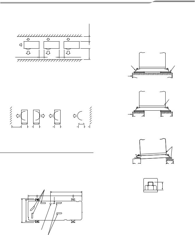
12FUNCTIONS TO BE IMPLEMENTED LOCALLY
Recovering Refrigerant
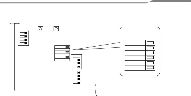
•Use the refrigerant recovery switch SW801 on the P.C. board of the outdoor unit to recover refrigerant when the hydro unit or outdoor unit is moved.
Procedure
1.Drain off the water in the hydro unit.
2.Turn on the power of the Air to Water Heat Pump.
3.Set SW804 on the P.C. board of the outdoor unit to all OFF, and then press SW801 for one second or more. The Air to Water Heat Pump enters the forced cooling mode for up to 10 minutes. Operation or handling the valve to recover refrigerant during this time period.
4.Upon completion of refrigerant recovery, close the valve and press SW801 for at least one second to stop operation.
5.Turn off the power.
Refrigerant
recovery P.C. board
switch SW801
Optional connector CN610
Special operation selectswitch SW804
|
4 |
|
3 |
ON |
1 2 |
|
4 |
|
3 |
ON |
1 2 |
 DANGER
Take care for an electric shock because the P.C.board is electrified.
19-EN |
– 20 – |

Air to Water Heat Pump |
Outdoor Unit Installation Manual |
13TROUBLESHOOTING
You can perform fault diagnosis of the outdoor unit with the LEDs on the P.C. board of the outdoor unit in addition to check codes displayed on the wired remote controller of the hydro unit.
Use the LEDs and check codes for various checks. Details of check codes displayed on the wired remote controller of the hydro unit are described in the Installation Manual of the hydro unit.
Check of the current abnormal status
1.Check that DIP switch SW803 is set to all OFF.
2.Jot down the states of LED800 to LED804. (Display mode 1)
3.Press SW800 for at least one second. The LED status changes to display mode 2.
4.Check the code whose display mode 1 equals the jotted LED status and display mode 2 equals the current flashing status of LED800 to LED804 from the following table to identify the cause.
Check of the abnormal status in the past although the abnormal status is not occurred now.
1.Set bit 1 of DIP switch SW803 to ON.
2.Jot down the states of LED800 to LED804. (Display mode 1)
3.Press SW800 for at least one second. The LED status changes to display mode 2.
4.Find an error whose display mode 1 equals the jotted LED status and display mode 2 equals the current flashing status of LED800 to LED804 from the following table to identify the error.
•An outside air temperature (TO) sensor error can be checked only while an error occurs.
No. |
Cause |
|
Display mode 1 |
|
|
Display mode 2 |
|
|||||
D800 |
D801 |
D802 |
D803 |
D804 |
D800 |
D801 |
D802 |
D803 |
D804 |
|||
|
|
|||||||||||
1 |
Normal |
● |
● |
● |
● |
● |
● |
● |
● |
● |
● |
2 |
Discharge (TD) sensor error |
{ |
{ |
● |
● |
{ |
● |
● |
|
● |
● |
3 |
Heat exchanger (TE) sensor error |
{ |
{ |
● |
● |
{ |
● |
|
|
● |
● |
4 |
Heat exchanger (TL) sensor error |
{ |
{ |
● |
● |
{ |
|
|
|
● |
● |
5 |
Outside air temperature (TO) sensor error |
{ |
{ |
● |
● |
{ |
● |
● |
● |
|
● |
6 |
Suction (TS) sensor error |
{ |
{ |
● |
● |
{ |
● |
● |
|
|
● |
7 |
Heat sink (TH) sensor error |
{ |
{ |
● |
● |
{ |
|
● |
|
|
● |
8 |
Outdoor temperature sensor (TE/TS) connection error |
{ |
{ |
● |
● |
{ |
|
|
|
|
● |
9 |
Outdoor EEPROM error |
{ |
{ |
● |
● |
{ |
|
|
|
|
|
10 |
Compressor lock |
● |
● |
{ |
● |
{ |
|
● |
● |
● |
● |
11 |
Compressor lock |
● |
● |
{ |
● |
{ |
● |
|
● |
● |
● |
12 |
Current detect circuit error |
● |
● |
{ |
● |
{ |
|
|
● |
● |
● |
13 |
Thermostat for compressor activated |
● |
● |
{ |
● |
{ |
● |
● |
|
● |
● |
14 |
Model data not set |
● |
{ |
{ |
● |
{ |
● |
|
● |
|
● |
(on the service P.C. board) |
|
|
|||||||||
|
|
|
|
|
|
|
|
|
|
|
|
15 |
MCU-MCU communication error |
● |
{ |
{ |
● |
{ |
|
● |
|
|
|
16 |
Discharge temperature error |
{ |
{ |
{ |
● |
{ |
|
|
● |
● |
● |
17 |
Abnormal power |
{ |
{ |
{ |
|
{ |
|
|
|
|
EN |
● |
|
● |
|
● |
● |
||||||
(open phase detected or abnormal voltage) |
|
|
|||||||||
|
|
|
|
|
|
|
|
|
|
|
|
18 |
Heat sink overheat |
{ |
{ |
{ |
● |
{ |
|
|
|
● |
● |
19 |
Gas leak detected |
{ |
{ |
{ |
● |
{ |
|
|
|
|
● |
20 |
4-way valve reverse error |
{ |
{ |
{ |
● |
{ |
|
|
● |
● |
|
21 |
High pressure release operation |
{ |
{ |
{ |
● |
{ |
● |
● |
|
● |
|
22 |
Outdoor fan motor error |
{ |
{ |
{ |
● |
{ |
● |
|
|
● |
|
23 |
Compressor driver short-circuit protection |
{ |
{ |
{ |
● |
{ |
● |
|
● |
|
|
24 |
Position detect circuit error in one-line display |
{ |
{ |
{ |
● |
{ |
|
● |
|
|
|
(●:OFF {:ON  :Flashing)
– 21 – |
20-EN |
Air to Water Heat Pump |
Outdoor Unit Installation Manual |
* The LEDs and DIP switches are located at the lower left of the P.C. board of the outdoor unit.
|
4 |
|
3 |
|
2 |
ON |
1 |
SW804
SW801 SW800
LED
D800
D801
D802
D803
D804
D805

 4
4
ON |
|
2 3 |
SW803 |
|
|
|
|||
|
||||
|
|
|
|
|
1 |
|
|||
|
|
|
|
|
|
|
|
|
|
|
|
|
||
|
4 |
|
||
ON |
|
|
2 3 |
SW802 |
|
|
|||
|
|
|||
|
||||
|
|
|
|
|
1 |
|
|||
|
|
|
|
|
Enlarged view of LEDs
D800
D801
D802
D803
D804
D805
14APPENDIX
Curing of pipes
When removing and opening the hydro unit or outdoor unit for a long time, cure the pipes as follows:
•Otherwise rust may generate when moisture or foreign matter due to dewing enters in the pipes.
•The rust cannot be removed by cleaning, and a new piping work is necessary.
Place position |
Term |
Curing manner |
||
|
|
|
|
|
Outdoors |
|
1 month or more |
Pinching |
|
|
|
|
||
|
Less than 1 month |
Pinching or taping |
||
|
|
|||
|
|
|
||
Hydro units |
Every time |
|||
|
||||
|
|
|
|
|
21-EN |
– 22 – |

Air to Water Heat Pump |
|
|
|
|
|
|
|
|
|
|
|
Outdoor Unit Installation Manual |
|
|
|
|
|
|
|
|
|
|
|
|
|
|
|
|
|
|
|
|
|
|
|
|
|
|
|
|
|
|
|
|
|
|
|
|
|
|
|
|
|
|
|
|
|
|
|
|
|
|
|
|
|
|
|
|
|
|
|
|
|
|
|
|
|
|
|
|
|
|
|
|
|
|
|
|
|
|
|
|
|
|
|
|
|
|
|
|
|
|
|
IMPORTANT INFORMATION AND WARNING:
READ BEFORE INSTALLING THE UNIT. KEEP IN A SAFE PLACE THE INFORMATION IN THIS BOOKLET IS NEEDED FOR END OF LIFE, DISPOSAL OR REUSE OF THE UNIT
•We are very sensitive to environment and welcomes the 2002/96/EC Directive WEEE (Waste Electrical and Electronic Equipment).
•This product is compliant with EU directive 2002/96/EC. It must be collected separately after its use is completed, and cannot be disposed as unsorted municipal waste.
•The objectived of EU directive 2002/96/EC are to tackle the fast increasing waste stream of electrical and electronic equipment, increase recycling of electric & electronic equipment ("EEE"), and to limit the total quantity of waste EEE ("WEEE") going to final disposal.
•The crossed out wheeled bin symbol  that is affixed to the product means that this product falls under the Directive.
•The user is responsible for returning the product to the appropriate collection facility, as specified by your municipality or the distributor. In case of installation of a new product, it may be possible to have the distributor pick up old WEEE directly.
•The producer, importer and distributor of are responsible for collection and treatment of waste, either directly or through a collective system. The list of our distributor in each country is shown in the attached table.
•In case of violation of the Directive, sanctions are set in each country.
•We are in general following the "CECED interpretation", and consider the WEEE applicable to Portable units, Dehumidifiers, WRACs (Window Room Air to Water Heat Pumps), Split Systems up to 12 kW, plug in refrigerators and freezers.
•Nevertheless, there may be difference among member state laws. In case country law exclude some products from WEEE scope, country law must be followed, and WEEE obligations do not have to be followed for products that fall out of country low scope.
•This directive does not apply to products sold outside European Community. In case the product is sold out of Eu, WEEE obligations do not have to be followed, while compliance with local regulation must be ensured.
•For additional information, please contact the municipal facility, the shop/dealer/installer that have sold the product, or the producer.
Country
Name of Company responsible for WEEE.
|
|
|
|
|
|
|
AIRCOND, Klimaanlagen |
|
Austria |
Handelsgesellshcaft m.b.H |
|
Petesgasse 45, A-8010 |
||
|
||
|
Graz Austria |
|
|
|
|
Belgium |
DOLPHIN NV, Fotografi |
|
elaan 12, B-2610, |
||
|
Antwerpen Belgium |
|
|
Carrier Hellas |
|
Cyprus |
Airconditioning S.A.- 4g |
|
Andersen street-11525 |
||
|
||
|
Athens Greece |
|
|
|
|
Denmark |
GIDEX A/S, Korshoj 10, |
|
3600 Frederikssund, |
||
|
Denmark |
|
Estonia |
Carrier OY Linnavuorentie |
|
28A 00950 Helsinki Finland |
||
|
||
Finland |
Carrier OY Linnavuorentie |
|
28A 00950 Helsinki Finland |
||
|
||
France |
Carrier S.A. Route de Thil |
|
BP 49 01122 Montiuel |
||
|
Cedex France |
|
Germany |
Carrier GmbH & Co. KG |
|
Edisonstrasse 2 85716 |
||
|
Unterschleissheim |
|
|
Carrier Hellas |
|
Greece |
Aircondilioning S.A.- 4g |
|
Andersen street-11525 |
||
|
||
|
Athens Greece |
|
|
|
|
|
|
|
|
|
|
INTERCOOL Technics BV |
|
Holland |
Nikkelstraat 39, Postbus 76 |
|
2980 AB Ridderkerk |
||
|
||
|
Netherlands |
|
|
|
|
Ireland |
GT Phelan Unit 30 Southern |
|
Cross Business Park Bray |
||
|
Co Wicklow Ireland |
|
Italy |
Carrier SpA Via R. Sanzio, 9 |
|
20058 Villasanta (Milano) |
||
|
Italy |
|
Latvia |
Carrier OY Linnavuorentie |
|
28A 00950 Helsinki Finland |
||
|
||
Lithuania |
Carrier OY Linnavuorenlie |
|
28A 00950 Helsinki Finland |
||
|
||
Luxembourg |
DOLPHIN NV Fotografi |
|
elaan 12, B-2610, |
||
|
Antwerpen Belgium |
|
|
CUTRICO Services Ltd, |
|
Malta |
Cutrico Building Psala |
|
Street, Sta Venea HMR 16 |
||
|
||
|
Malta |
|
|
|
|
Norway |
Carrier AB - P.O.BOX 8946- |
|
Arods Industrivag 32. S-402 |
||
|
73 Gothenburg Sweden |
|
Poland |
Carrier Polska Sp. Z.o.o. |
|
Postepu 14 02-676 Warsaw |
||
|
Poland |
|
|
|
||
|
|
|
|
|
|
Carrier Portugal - AR |
|
||
Portugal |
Condicionado LDA Avenida |
|
||
do Forte, Nr. 3 Editi cio |
|
|||
|
Suecia l,Piso 1 Camaxide |
|
||
|
2794-043 Portugal |
|
|
|
|
Toshiba Carrier UK Ltd |
|
||
UK |
Porsham Close, Belliver Ind. |
|
||
Est. Plymouth, Devon, PL6 |
|
|||
|
|
|||
|
7DB |
|
||
|
|
|
|
|
Czech |
AIRCOND, , Klimaanlagen |
|
||
Handelsgesellshcaft m.b.H |
|
|||
Republic |
Petersgasse 45, A-8010 |
|
||
|
Graz Austria |
|
|
|
|
AIRCOND, , Klimaanlagen |
|
||
Slovakia |
Handelsgesellshcaft m.b.H |
|
||
Petersgasse 45, A-8010 |
|
|||
|
|
|||
|
Graz Austria |
|
||
|
|
|
|
|
|
AIRCOND, , Klimaanlagen- |
|
||
Slovenia |
Handelsgesellshcaft m.b.H, |
|
||
|
||||
Petersgasse 45, A-8010 |
EN |
|||
|
||||
|
Graz, Austria |
|
||
|
Carrier Espana S.L. - Paseo |
|
||
Spain |
Castellana 36-38, 28046 |
|
||
|
Madrid |
|
||
|
|
|
|
|
Sweden |
Carrier AB - P.O.BOX 8946- |
|
||
Arods Industrivag 32 . S-402 |
|
|||
|
73 Gothenburg |
|
|
|
|
AIRCOND, Klimaanlagen |
|
||
Hungary |
Handelsgesellshcaft m.b.H |
|
||
Petersgasse 45, A-8010 |
|
|||
|
|
|||
|
Graz Austria |
|
||
|
|
|
|
|
The manufacturer reserves the right to change any product specifications without notice.
– 23 – |
22-EN |

Air to Water Heat Pump |
Outdoor Unit Installation Manual |
Avant d’installer la pompe à chaleur air/eau, lisez attentivement ce Manuel d’installation.
•Ce manuel décrit la méthode d’installation de l’unité extérieure.
•Pour l’installation de l’unité hydroélectrique, reportez-vous au Manuel d’installation fourni avec l’unité hydroélectrique.
ADOPTION DU NOUVEAU REFRIGERANT
Cette pompe à chaleur air/eau est un nouveau type qui adopte un nouveau réfrigérant HFC (R410A) au lieu du réfrigérant traditionnel R22 en vue d’éviter la destruction de la couche d’ozone.
Sommaire |
|
|
1 |
PIECES ACCESSOIRES ET REFRIGERANT . . . . . . . . . . . . . . . . . . . . . . . . . . . . . . . |
25 |
2 |
MESURES DE SECURITE . . . . . . . . . . . . . . . . . . . . . . . . . . . . . . . . . . . . . . . . . . . . . . |
26 |
3 |
INSTALLATION DU NOUVEAU REFRIGERANT DANS LA |
|
|
POMPE A CHALEUR AIR/EAU . . . . . . . . . . . . . . . . . . . . . . . . . . . . . . . . . . . . . . . . . . |
27 |
4 |
CHOIX DE L’INSTALLATION . . . . . . . . . . . . . . . . . . . . . . . . . . . . . . . . . . . . . . . . . . . |
29 |
5 |
TUYAUX DE REFRIGERANT . . . . . . . . . . . . . . . . . . . . . . . . . . . . . . . . . . . . . . . . . . . |
34 |
6 |
PURGE D’AIR . . . . . . . . . . . . . . . . . . . . . . . . . . . . . . . . . . . . . . . . . . . . . . . . . . . . . . . |
37 |
7 |
INSTALLATION ELECTRIQUE . . . . . . . . . . . . . . . . . . . . . . . . . . . . . . . . . . . . . . . . . . |
39 |
8 |
MISE A LA TERRE . . . . . . . . . . . . . . . . . . . . . . . . . . . . . . . . . . . . . . . . . . . . . . . . . . . |
41 |
9 |
FINITION . . . . . . . . . . . . . . . . . . . . . . . . . . . . . . . . . . . . . . . . . . . . . . . . . . . . . . . . . . . |
41 |
10 ESSAI DE FONCTIONNEMENT . . . . . . . . . . . . . . . . . . . . . . . . . . . . . . . . . . . . . . . . . |
41 |
|
11 ENTRETIEN ANNUEL . . . . . . . . . . . . . . . . . . . . . . . . . . . . . . . . . . . . . . . . . . . . . . . . . |
41 |
|
12 FONCTIONS A EXECUTER LOCALEMENT . . . . . . . . . . . . . . . . . . . . . . . . . . . . . . . |
42 |
|
13 DEPANNAGE . . . . . . . . . . . . . . . . . . . . . . . . . . . . . . . . . . . . . . . . . . . . . . . . . . . . . . . . |
43 |
|
14 ANNEXE . . . . . . . . . . . . . . . . . . . . . . . . . . . . . . . . . . . . . . . . . . . . . . . . . . . . . . . . . . . . |
44 |
|
1-FR |
– 24 – |
Air to Water Heat Pump |
Outdoor Unit Installation Manual |
1 PIECES ACCESSOIRES ET REFRIGERANT
Pièces accessoires
Nom de la pièce |
Quantité |
Forme |
Emploi |
|
Manuel d’installation de |
1 |
Ce manuel |
(Remettez celui-ci directement au client.) |
|
l’unité extérieure |
||||
|
|
|
||
Raccord d’évacuation |
1 |
|
|
|
Bouchon en caoutchouc |
5 |
|
|
|
étanche |
|
|
||
|
|
|
||
Manchon de protection |
1 |
|
Pour la protection des câbles (protection des tuyaux) |
|
Matériau de protection |
1 |
|
Pour la protection des passages (protection des tuyaux) |
|
pour passages |
|
|||
|
|
|
Tuyaux de réfrigérant
•Le kit de tuyaux utilisé pour le réfrigérant traditionnel ne peut être utilisé.
•Utilisez un tuyau en cuivre de 0,8 mm ou plus d’épaisseur pour Ø9,5 mm. Utilisez un tuyau en cuivre de 1,0 mm ou plus d’épaisseur pour Ø15,9 mm.
•Les écrous évasés et l’évasement diffèrent également de ceux des tuyaux du réfrigérant traditionnel. Retirez l’écrou évasé fourni avec la pompe à chaleur air/eau et utilisez-le.
FR
– 25 – |
2-FR |

Air to Water Heat Pump |
Outdoor Unit Installation Manual |
2 MESURES DE SECURITE
•Assurez-vous de respecter toutes les règles locales, nationales et internationales.
•Lisez attentivement ces « MESURES DE SECURITE » avant l’installation.
•Les mesures décrites ci-après comprennent des points importants concernant la sécurité. Observez-les scrupuleusement.
•Après l’installation, faites un essai de fonctionnement pour vous assurer de l’absence de problèmes. Reportez-vous au Manuel du propriétaire pour expliquer au client comment utiliser l’unité et effectuer son entretien.
•Mettez l’interrupteur général (ou le disjoncteur) hors tension avant d’effectuer l’entretien de l’unité.
•Demandez au client de conserver le Manuel d’installation avec le Manuel du propriétaire.
 AVERTISSEMENT
•Demandez à un revendeur autorisé ou à un installateur professionnel d’installer la pompe à chaleur air/eau ou d’effectuer son entretien.
Une installation inadéquate peut se solder par une fuite d’eau, une électrocution ou un incendie.
•Veillez à raccorder les fils de terre. (mise à la terre)
Une mise à la terre incomplète provoque une électrocution.
Ne raccordez pas les fils de terre aux tuyaux de gaz, aux tuyaux d’eau, aux paratonnerres ou aux fils de terre des câbles téléphoniques.
•Mettez l’interrupteur général ou le disjoncteur hors tension avant d’entreprendre l’installation électrique.
Assurez-vous que tous les interrupteurs sont hors tension. La non-observation de cet avertissement peut se solder par une électrocution.
Utilisez un circuit d’alimentation exclusif pour la pompe à chaleur air/eau. Utilisez la tension nominale.
•Branchez correctement le câble de raccordement.
Si le câble de raccordement est mal branché, les composants électriques peuvent s’endommager.
•Lorsque vous déplacez la pompe à chaleur air/eau pour l’installer ailleurs, faites très attention à ce qu’aucun corps gazeux autre que le réfrigérant spécifié ne pénètre dans le circuit de réfrigération.
Si l’air ou tout autre gaz se mélange au réfrigérant, la pression gazeuse du circuit de réfrigération augmentera anormalement et pourra faire éclater les tuyaux et blesser quelqu’un.
•Ne modifiez pas cette unité en démontant ses carters de protection ou en by-passant ses verrous de sûreté.
•Après avoir déballé l’unité, examinez-la attentivement pour vous assurer qu’elle n’est pas endommagée.
•Ne l’installez pas dans un endroit susceptible d’augmenter ses vibrations.
•Afin d’éviter de vous blesser (avec des bords tranchants), faites attention lorsque vous manipulez les pièces.
•Effectuez l’installation conformément au Manuel d’installation.
Une installation inadéquate peut se solder par une fuite d’eau, une électrocution ou un incendie.
•Si l’unité hydroélectrique de la pompe à chaleur air/eau est installée dans une petite pièce, prenez les mesures appropriées pour garantir que la concentration de fuite de réfrigérant dans la pièce ne dépasse pas le niveau critique.
•Serrez l’écrou évasé avec une clé dynamométrique de la manière spécifiée.
Un serrage excessif de l’écrou évasé peut se solder par une rupture de l’écrou évasé après une longue période, ce qui peut entraîner une fuite de réfrigérant.
•Portez des gants épais pendant l’installation pour éviter de vous blesser.
•Installez solidement la pompe à chaleur air/eau dans un endroit qui supporte son poids de manière adéquate.
•Effectuez l’installation spécifiée pour protéger le climatiseur contre un tremblement de terre.
Si la pompe à chaleur air/eau n’est pas installée de manière appropriée, elle peut tomber et provoquer des accidents.
•Si le gaz réfrigérant a fui durant l’installation, aérez immédiatement la pièce.
Si le gaz réfrigérant qui a fui entre en contact avec le feu, un gaz nocif peut se dégager.
•Après l’installation, assurez-vous que le gaz réfrigérant ne fuit pas.
Si le gaz réfrigérant fuit dans la pièce et s’écoule près d’un appareil ignigène, comme une cuisinière, un gaz nocif peut se dégager.
•L’installation électrique doit être effectuée par un électricien professionnel conformément au Manuel d’installation. Assurez-vous que la pompe à chaleur air/eau utilise une alimentation exclusive.
Une alimentation de puissance insuffisante ou une installation inappropriée peuvent provoquer un incendie.
•Utilisez les câbles spécifiés et raccordez-les bien aux bornes.
Evitez qu’une pression externe ne s’exerce sur les bornes et ne les affecte.
3-FR |
– 26 – |

Air to Water Heat Pump |
Outdoor Unit Installation Manual |
 AVERTISSEMENT
•Lorsque la pompe à chaleur air/eau ne peut pas refroidir ou chauffer convenablement une pièce, contactez le revendeur qui vous l’a vendue si une fuite de réfrigérant est susceptible d’être la cause.
En cas de réparation requérant le remplissage de réfrigérant, demandez les détails de la réparation au personnel chargé de l’entretien.
Le réfrigérant utilisé dans la pompe à chaleur air/eau est inoffensif.
Généralement, le réfrigérant ne fuit pas. Cependant, si le réfrigérant fuit dans une pièce et qu’un chauffage ou une cuisinière prend feu, un gaz toxique peut se dégager.
Si vous demandez au personnel chargé de l’entretien de réparer la fuite de réfrigérant, vérifiez que la partie qui fuyait a été complètement réparée.
•Observez les règles de la compagnie d’électricité locale lorsque vous raccordez les câbles d’alimentation.
Une mise à la terre inappropriée peut provoquer une électrocution.
•N’installez pas la pompe à chaleur air/eau dans un endroit susceptible d’être exposé à des gaz inflammables.
Si un gaz inflammable fuit et stagne autour de l’unité, il peut provoquer un incendie.
•Installez solidement le tuyau de réfrigérant pendant l’installation avant d’utiliser la pompe à chaleur air/eau.
Si le compresseur fonctionne avec la soupape ouverte et sans le tuyau de réfrigérant, le compresseur aspire l’air et le circuit de réfrigération est surpressurisé, ce qui peut faire éclater l’unité et blesser quelqu’un.
•Pour la récupération du réfrigérant (collecte du réfrigérant du tuyau vers le compresseur), arrêtez le compresseur avant de débrancher le tuyau de réfrigérant.
Si le tuyau de réfrigérant est débranché alors que le compresseur fonctionne avec la soupape ouverte, le compresseur aspire l’air et le circuit de réfrigération est surpressurisé, ce qui peut faire éclater l’unité et blesser quelqu’un.
 ATTENTION
Installation du nouveau réfrigérant dans la pompe à chaleur air/eau
•CETTE POMPE A CHALEUR AIR/EAU UTILISE LE NOUVEAU REFRIGERANT HFC (R410A) QUI NE DETRUIT PAS LA COUCHE D’OZONE.
•Le réfrigérant R410A se distingue par son absorption aisée de l’eau, de la membrane oxydante ou de l’huile ainsi que par sa pression, qui est d’environ 1,6 fois celle du réfrigérant R22. Outre l’utilisation du nouveau réfrigérant, l’huile réfrigérante a elle aussi été remplacée. Par conséquent, durant l’installation, assurez-vous que l’eau, la poussière, le réfrigérant précédent ou l’huile réfrigérante n’entrent pas dans le circuit de réfrigération.
•Pour éviter de remplir du réfrigérant et de l’huile réfrigérante inappropriés, la taille des sections de raccordement de l’orifice de remplissage de l’unité principale et les outils d’installation sont différents de ceux qui sont utilisés pour le réfrigérant traditionnel.
•En conséquence, les outils exclusifs sont requis pour le nouveau réfrigérant (R410A).
•Quant aux tuyaux de raccordement, utilisez des tuyaux neufs et propres conçus pour le R410A et veillez à ce que l’eau ou la poussière n’y entrent pas.
Pour déconnecter l’appareil du secteur
•Cet appareil doit être connecté au secteur via un interrupteur ayant une séparation de contact d’au moins 3 mm.
•Vous devez utiliser le fusible d’installation 25 A (vous pouvez utiliser n’importe quel type de fusible) sur la ligne d’alimentation de cette unité.
3 INSTALLATION DU NOUVEAU REFRIGERANT |
|
DANS LA POMPE A CHALEUR AIR/EAU |
FR |
•Le réfrigérant R410A est plus sensible aux impuretés telles que l’eau, la membrane oxydante, les huiles et les graisses. Outre l’adoption du nouveau réfrigérant, l’huile réfrigérante a elle aussi été remplacée.
Veillez à ce que l’eau, la poussière, le réfrigérant traditionnel et/ou l’huile réfrigérante traditionnelle ne pénètrent pas dans le circuit de réfrigération de la pompe à chaleur air/eau utilisant le nouveau réfrigérant.
•Pour éviter le mélange de différents réfrigérants ou huiles réfrigérantes, la taille des sections de raccordement de l’orifice de remplissage de l’unité et l’outil d’installation sont différents de ceux utilisés pour le réfrigérant traditionnel. En conséquence, les outils exclusifs suivants sont requis pour le nouveau réfrigérant (R410A).
– 27 – |
4-FR |
 Loading...