


Ref.-No. SMMS01-AE-01-05
Indoor unit
4-way ceiling cassette
MMU-AP0091H, AP0121H, AP0151H, MMU-AP0181H, AP0241H, AP0271H, MMU-AP0301H, AP0361H, AP0481H MMU-AP0561H
2-way ceiling cassette
MMU-AP0071WH, AP0091WH, AP0121WH, MMU-AP0151WH, AP0181WH, AP0241WH, MMU-AP0271WH, AP0301WH
1-way ceiling cassette
MMU-AP0071YH, AP0091YH, AP0121YH, MMU-AP0151SH, AP0181SH, AP0241SH
Standard ducted unit
MMD-AP0071BH, AP0091BH, AP0121BH, MMD-AP0151BH, AP0181BH, AP0241BH, MMD-AP0271BH, AP0301BH, AP0361BH, MMD-AP0481BH, AP0561BH
High-pressure ducted unit
MMD-AP0181H, AP0241H, AP0271H, MMD-AP0361H, AP0481H, AP0721H, MMD-AP0961H
Slim duct unit
MMD-AP0071SPH, AP0091SPH, MMD-AP0121SPH, AP0151SPH, MMD-AP0181SPH
Ceiling-suspended unit
MMC-AP0151H, AP0181H, AP0241H, MMC-AP0271H, AP0361H, AP0481H
High-wall unit
MMK-AP0071H, AP0091H, AP0121H, MMK-AP0151H, AP0181H, AP0241H MMK-AP0072H, AP0092H, AP0122H
Super Modular Multi
Design Manual
Floor-mounted console unit
MML-AP0071H, AP0091H, AP0121H, MML-AP0151H, AP0181H, AP0241H
Concealed chassis unit
MML-AP0071BH, AP0091BH, AP0121BH, MML-AP0151BH, AP0181BH, AP0241BH
HFC R-410A
Outdoor unit
Floor-mounted cabinet unit MMF-AP0151H, AP0181H, AP0241H MMF-AP0271H, AP0361H, AP0481H MMF-AP0561H
COOLING ONLY MODEL
Inverter unit
MMY-MAP0501T8, MAP0601T8 MMY-MAP0801T8, MAP1001T8 MMY-MAP1201T8
HEAT PUMP MODEL
Inverter unit
MMY-MAP0501HT8, MAP0601HT8 MMY-MAP0801HT8, MAP1001HT8 MMY-MAP1201HT8
Super Modular Multi System
Contents |
|
|
1. |
Outline of Toshiba Super Modular Multi System (S-MMS) .................................................................................. |
4 |
2. |
Summary of system equipment ........................................................................................................................... |
7 |
3. |
Basic system configuration.................................................................................................................................. |
13 |
4. |
Equipment selection procedure ........................................................................................................................... |
19 |
5. |
Refrigerant piping design..................................................................................................................................... |
29 |
6. |
Wiring design ....................................................................................................................................................... |
34 |
7. |
Controls................................................................................................................................................................ |
39 |
8. |
Accessories.......................................................................................................................................................... |
45 |
9. |
Technical specifications ....................................................................................................................................... |
46 |
10. |
Fan characteristics............................................................................................................................................... |
69 |
11. |
Dimensional drawings.......................................................................................................................................... |
75 |
This manual is used for both cooling only and heat pump models.
3

1.Outline of Toshiba Super Modular Multi System (S-MMS)
 Branching
Combination of line and header branching is highly flexible. This allows for the shortest design route possible, thereby saving on installation time and cost. Line/header branching after header branching is only available with Toshiba Super MMS.
Line branching
Outdoor unit
Branching joint
Indoor unit


Header branching
Outdoor unit
Branching header
Indoor unit 
Line and header branching
Header
Outdoor unit |
|
|
Branching joint |
Indoor |
|
unit |
||
|
Line branching after header branching
Outdoor unit
Header |
Branching joint |
|
Super MMS
only
Indoor unit 

Header branching after header branching
Outdoor unit
Header
Super MMS
only
Header
Indoor unit 
8F
7F
2F
1F
4

8F
7F
2F

1F
•Non-polarized control wiring between outdoor and indoor units
Outdoor unit
Indoor unit
•Wiring diagnosis system
Use the switches on the micro processor PCB of the outdoor unit.
•Detects wiring to the indoor unit a4 which should not be in system A.
•b4 is missing in system B.
Outdoor unit Piping
A system
Wiring |
Indoor unit |
B |
|
system |
|
Outdoor unit |
|
|
|
|
|
Allowable pipe length: |
|
|
|
Outdoor unit |
175 m equivalent length |
|
|
|
1st branching |
|
|
and outdoor unit: 50 m |
|
section |
|
difference between |
difference between |
units: 30 m |
|
|
Height |
indoor |
Height |
indoor |
|
From 1st branching to the farthest indoor unit: 65 m
5

Compact
The design of the modular Toshiba Super MMS outdoor unit allows for easy unit manoeuvring into any standard lift. Its compactness also allows it to be easily installed in limited spaces.
Largest system capacity
Toshiba Super MMS can be combined up to 48 hp (135 kW) as one refrigerant system.
Energy saving design
The units have the best energy efficiency ratio of any VRF unit. Compared with a conventional chiller fan coil system, a large energy saving can be realized.
Advanced bus communication system
Wiring between indoor and outdoor units is a simple 2-wire system. The communication address is also automatically configured.
A default test mode operation is available.
Self-diagnostic system
Comprehensive troubleshooting code enables quick identification of problems arising.
High lift design
An equivalent pipe length of 175 m and vertical lift of 50 m are possible with the Toshiba Super MMS.
The vertical lift between indoor units of 30 m is the highest in the industry. This allows for greater flexibility in the location of the system.
Multiple indoor units
Indoor units with different capacities and configurations can be combined up to 135% of the outdoor unit capacity.
A maximum of 48 indoor units can be combined with the 30-48 hp outdoor units.
Intelligent control
Toshiba Super MMS intelligent controls and modulating valves deliver the required capacity, in accordance with the load variation from 50% to 100%.
The intelligent controls and modulating valves limit or increase the cooling capacity dynamically so humidity and temperature are kept in the comfort zone.
Wide control applications
Artificial Intelligence Network system
•Central control and monitoring system available
•Weekly schedule operation through weekly timer
Integration with a Building Management System (BMS) is available.
6

2.Summary of system equipment
Technical specifications - outdoor units
Rating |
hp |
5 |
6 |
8 |
10 |
12 |
|
Cooling only model MMY-MAP |
|
0501T8 |
0601T8 |
0801T8 |
1001T8 |
1201T8 |
|
Heat pump model MMY-MAP |
|
0501HT8 |
0601HT8 |
0801HT8 |
1001HT8 |
1201HT8 |
|
Cooling capacity |
kW |
14.0 |
16.0 |
22.4 |
28.0 |
33.5 |
|
Heating capacity |
kW |
16.0 |
18.0 |
25.0 |
31.5 |
37.5 |
|
Technical specifications - combination of outdoor units
Rating |
hp |
5 |
6 |
8 |
10 |
12 |
14 |
16 |
Cooling only model MMY-MAP |
|
0501T8 |
0601T8 |
0801T8 |
1001T8 |
1201T8 |
1401T8 |
1601T8 |
Heat pump model MMY-MAP |
|
0501HT8 |
0601HT8 |
0801HT8 |
1001HT8 |
1201HT8 |
1401HT8 |
1601HT8 |
Cooling capacity |
kW |
14.0 |
16.0 |
22.4 |
28.0 |
33.5 |
38.4 |
45.0 |
Heating capacity |
kW |
16.0 |
18.0 |
25.0 |
31.5 |
37.5 |
43.0 |
50.0 |
Combined outdoor units |
hp |
5 |
6 |
8 |
10 |
12 |
8 |
8 |
|
|
- |
- |
- |
- |
- |
6 |
8 |
No. of connectable indoor units |
|
8 |
10 |
13 |
16 |
20 |
23 |
27 |
|
|
|
|
|
|
|
|
|
Rating |
hp |
18 |
20 |
22 |
22 |
24 |
24 |
26 |
Cooling only model MMY-MAP |
|
1801T8 |
2001T8 |
2201T8 |
2211T8 |
2401T8 |
2411T8 |
2601T8 |
Heat pump model MMY-MAP |
|
1801HT8 |
2001HT8 |
2201HT8 |
2211HT8 |
2401HT8 |
2411HT8 |
2601HT8 |
Cooling capacity |
kW |
50.4 |
56.0 |
61.5 |
61.5 |
68.0 |
68.0 |
73.0 |
Heating capacity |
kW |
56.5 |
63.0 |
69.0 |
69.0 |
76.5 |
76.5 |
81.5 |
Combined outdoor units |
hp |
10 |
10 |
8 |
12 |
8 |
12 |
10 |
|
|
8 |
10 |
8 |
10 |
8 |
12 |
8 |
|
|
- |
- |
6 |
- |
8 |
- |
8 |
No. of connectable indoor units |
|
30 |
33 |
37 |
37 |
40 |
40 |
43 |
|
|
|
|
|
|
|
|
|
Rating |
hp |
28 |
30 |
32 |
32 |
34 |
34 |
36 |
Cooling only model MMY-MAP |
|
2801T8 |
3001T8 |
3201T8 |
3211T8 |
3401T8 |
3411T8 |
3601T8 |
Heat pump model MMY-MAP |
|
2801HT8 |
3001HT8 |
3201HT8 |
3211HT8 |
3401HT8 |
3411HT8 |
3601HT8 |
Cooling capacity |
kW |
78.5 |
84.0 |
90.0 |
90.0 |
96.0 |
96.0 |
101.0 |
Heating capacity |
kW |
88.0 |
95.0 |
100.0 |
100.0 |
108.0 |
108.0 |
113.0 |
Combined outdoor units |
hp |
10 |
10 |
8 |
12 |
10 |
12 |
10 |
|
|
10 |
10 |
8 |
10 |
8 |
12 |
10 |
|
|
8 |
10 |
8 |
10 |
8 |
10 |
8 |
|
|
- |
- |
8 |
- |
8 |
- |
8 |
No. of connectable indoor units |
|
47 |
48 |
48 |
48 |
48 |
48 |
48 |
|
|
|
|
|
|
|
|
|
Rating |
hp |
36 |
38 |
40 |
42 |
44 |
46 |
48 |
Cooling only model MMY-MAP |
|
3611T8 |
3801T8 |
4001T8 |
4201T8 |
4401T8 |
4601T8 |
4801T8 |
Heat pump model MMY-MAP |
|
3611HT8 |
3801HT8 |
4001HT8 |
4201HT8 |
4401HT8 |
4601HT8 |
4801HT8 |
Cooling capacity |
kW |
101.0 |
106.5 |
112.0 |
118.0 |
123.5 |
130.0 |
135.0 |
Heating capacity |
kW |
113.0 |
119.5 |
126.5 |
132.0 |
138.0 |
145.0 |
150.0 |
Combined outdoor units |
hp |
12 |
10 |
10 |
12 |
12 |
12 |
12 |
|
|
12 |
10 |
10 |
10 |
12 |
12 |
12 |
|
|
12 |
10 |
10 |
10 |
10 |
12 |
12 |
|
|
- |
8 |
10 |
10 |
10 |
10 |
12 |
No. of connectable indoor units |
|
48 |
48 |
48 |
48 |
48 |
48 |
48 |
Branching joints and headers
|
Model |
|
Usage |
|
|
|
|
Appearance |
||
Y-shape branching joint (*3) |
RBM-BY53E |
|
Indoor unit capacity code (*1) : Total below 6.4 |
|
|
|
|
|
|
|
|
RBM-BY103E |
|
Indoor unit capacity code (*1) : Total 6.4 or more and below 14.2 |
(*2) |
|
|
|
|
||
|
|
|
|
|
||||||
|
RBM-BY203E |
|
Indoor unit capacity code (*1) : Total 14.2 or more and below 25.2 |
(*2) |
|
|
|
|
||
|
RBM-BY303E |
|
Indoor unit capacity code (*1) : Total 25.2 or more |
(*2) |
|
|
|
|
||
4-branching header (*4) |
RBM-HY1043E |
|
Indoor unit capacity code (*1) : Total below 14.2 |
|
Max.4 |
|
||||
|
RBM-HY2043E |
|
Indoor unit capacity code (*1) : Total 14.2 or more and below 25.2 |
|
branches |
|
||||
8-branching header (*4) (*5) |
RBM-HY1083E |
|
Indoor unit capacity code (*1) : Total below 14.2 |
|
Max.8 |
|
|
|
||
|
RBM-HY2083E |
|
Indoor unit capacity code (*1) : Total 14.2 or more and below 25.2 |
|
branches |
|
||||
T-shape branching joint |
RBM-BT13E |
|
1 set of 3 types of T-shape joint pipes as described below: |
|
|
|
|
|
|
|
(For connection of |
|
|
The required quantity is arranged and they are combined at the site. |
|||||||
outdoor units) |
|
|
|
|
|
|
|
|
|
|
|
|
|
Connection piping |
Corresponding dia. (mm) |
Q’ty |
|
|
|
|
|
|
|
|
Balance pipe |
Ø3/8” |
1 |
|
|
|
|
|
|
|
|
Liquid side piping |
Ø3/8” to Ø7/8” |
1 |
|
|
|
|
|
|
|
|
Gas side piping |
Ø5/8” to Ø1-5/8” |
1 |
|
|
|
|
|
|
|
|
|
|
|
|
|
|
|
|
*1 The capacity code can be obtained from page 10 (capacity code is not actual capacity).
*2 If total capacity code value of indoor unit exceeds that of outdoor unit, apply capacity code of outdoor unit. *3 When using Y-shape branching joint for 1st branching, select according to capacity code of outdoor unit. *4 Max. 6.0 capacity code in total can be connected.
*5 If capacity code of outdoor unit is 26 and more, it is not used for 1st branching.
*6 Model names for outdoor and indoor units described in this guide are shortened because of the space constraints.
7

Outdoor unit model line-up - cooling only units
hp |
Model |
No. of |
Inverter |
Q’ty |
Inverter |
Q’ty |
Inverter |
Qty |
Inverter |
Q’ty |
Inverter |
Q’ty |
(capacity |
MMY- |
combined |
5 hp |
used |
6 hp |
used |
8 hp |
used |
10 hp |
used |
12 hp |
used |
code) |
|
units |
MMY- |
|
MMY- |
|
MMY- |
|
MMY- |
|
MMY- |
|
5 hp (5) |
MAP0501T8 |
1 |
MAP0501T8 |
1 |
|
|
|
|
|
|
|
|
6 hp (6) |
MAP0601T8 |
1 |
|
|
MAP0601T8 |
1 |
|
|
|
|
|
|
8 hp (8) |
MAP0801T8 |
1 |
|
|
|
|
MAP0801T8 |
|
|
|
|
|
10 hp (10) |
MAP1001T8 |
1 |
|
|
|
|
|
|
MAP1001T8 |
1 |
|
|
12 hp (12) |
MAP1201T8 |
1 |
|
|
|
|
|
|
|
|
MAP1201T8 |
1 |
14 hp (14) |
AP1401T8 |
2 |
|
|
MAP0601T8 |
1 |
MAP0801T8 |
|
|
|
|
|
16 hp (16) |
AP1601T8 |
2 |
|
|
|
|
MAP0801T8 |
2 |
|
|
|
|
18 hp (18) |
AP1801T8 |
2 |
|
|
|
|
MAP0801T8 |
1 |
MAP1001T8 |
1 |
|
|
20 hp (20) |
AP2001T8 |
2 |
|
|
|
|
|
|
MAP1001T8 |
2 |
|
|
22 hp (22) |
AP2201T8 |
3 |
|
|
MAP0601T8 |
1 |
MAP0801T8 |
2 |
|
|
|
|
22 hp (22) |
AP2211T8 |
2 |
|
|
|
|
|
|
MAP1001T8 |
1 |
MAP1201T8 |
1 |
24 hp (24) |
AP2401T8 |
3 |
|
|
|
|
MAP0801T8 |
3 |
|
|
|
|
24 hp (24) |
AP2411T8 |
2 |
|
|
|
|
|
|
|
|
MAP1201T8 |
2 |
26 hp (26) |
AP2601T8 |
3 |
|
|
|
|
MAP0801T8 |
2 |
MAP1001T8 |
1 |
|
|
28 hp (28) |
AP2801T8 |
3 |
|
|
|
|
MAP0801T8 |
1 |
MAP1001T8 |
2 |
|
|
30 hp (30) |
AP3001T8 |
3 |
|
|
|
|
|
|
MAP1001T8 |
3 |
|
|
32 hp (32) |
AP3201T8 |
4 |
|
|
|
|
MAP0801T8 |
4 |
|
|
|
|
32 hp (32) |
AP3211T8 |
3 |
|
|
|
|
|
|
MAP1001T8 |
2 |
MAP1201T8 |
1 |
34 hp (34) |
AP3401T8 |
4 |
|
|
|
|
MAP0801T8 |
3 |
MAP1001T8 |
1 |
|
|
34 hp (34) |
AP3411T8 |
3 |
|
|
|
|
|
|
MAP1001T8 |
1 |
MAP1201T8 |
2 |
36 hp (36) |
AP3601T8 |
4 |
|
|
|
|
MAP0801T8 |
2 |
MAP1001T8 |
2 |
|
|
36 hp (36) |
AP3611T8 |
3 |
|
|
|
|
|
|
|
|
MAP1201T8 |
3 |
38 hp (38) |
AP3801T8 |
4 |
|
|
|
|
MAP0801T8 |
1 |
MAP1001T8 |
3 |
|
|
40 hp (40) |
AP4001T8 |
4 |
|
|
|
|
|
|
MAP1001T8 |
4 |
|
|
42 hp (42) |
AP4201T8 |
4 |
|
|
|
|
|
|
MAP1001T8 |
3 |
MAP1201T8 |
1 |
44 hp (44) |
AP4401T8 |
4 |
|
|
|
|
|
|
MAP1001T8 |
2 |
MAP1201T8 |
2 |
46 hp (46) |
AP4601T8 |
4 |
|
|
|
|
|
|
MAP1001T8 |
1 |
MAP1201T8 |
3 |
48 hp (48) |
AP4801T8 |
4 |
|
|
|
|
|
|
|
|
MAP1201T8 |
4 |
1. Product designation
MMY- M AP 000 0 T 8
8: Power supply, 3 ph, 380-415 V, 50 Hz T: Inverter unit
Development series number
Model size hp x 10
New refrigerant R-410A
M: Single module unit. No mark: Combined model name
Super Modular Multi
2. Combined capacity range
No. of combined units: |
1 to 4 units |
Capacity of combined units: |
14 hp (140 type) to 48 hp (480 type) |
3. Rated conditions
Cooling: Indoor air temperature 27°C db/19°C wb, outdoor air temperature 35°C db.
8
Outdoor unit model line-up - heat pump units
hp |
Model |
No. of |
Inverter |
Q’ty |
Inverter |
Q’ty |
Inverter |
Qty |
Inverter |
Q’ty |
Inverter |
Q’ty |
(capacity |
MMY- |
combined |
5 hp |
used |
6 hp |
used |
8 hp |
used |
10 hp |
used |
12 hp |
used |
code) |
|
units |
MMY- |
|
MMY- |
|
MMY- |
|
MMY- |
|
MMY- |
|
5 hp ( 5) |
MAP0501HT8 |
1 |
MAP0501HT8 |
1 |
|
|
|
|
|
|
|
|
6 hp ( 6) |
MAP0601HT8 |
1 |
|
|
MAP0601HT8 |
1 |
|
|
|
|
|
|
8 hp ( 8) |
MAP0801HT8 |
1 |
|
|
|
|
MAP0801HT8 |
1 |
|
|
|
|
10 hp (10) |
MAP1001HT8 |
1 |
|
|
|
|
|
|
MAP1001HT8 |
1 |
|
|
12 hp (12) |
MAP1201HT8 |
1 |
|
|
|
|
|
|
|
|
MAP1201HT8 |
1 |
14 hp (14) |
AP1401HT8 |
2 |
|
|
MAP0601HT8 |
1 |
MAP0801HT8 |
1 |
|
|
|
|
16 hp (16) |
AP1601HT8 |
2 |
|
|
|
|
MAP0801HT8 |
2 |
|
|
|
|
18 hp (18) |
AP1801HT8 |
2 |
|
|
|
|
MAP0801HT8 |
1 |
MAP1001HT8 |
1 |
|
|
20 hp (20) |
AP2001HT8 |
2 |
|
|
|
|
|
|
MAP1001HT8 |
2 |
|
|
22 hp (22) |
AP2201HT8 |
3 |
|
|
MAP0601HT8 |
1 |
MAP0801HT8 |
2 |
|
|
|
|
22 hp (22) |
AP2211HT8 |
2 |
|
|
|
|
|
|
MAP1001HT8 |
1 |
MAP1201HT8 |
1 |
24 hp (24) |
AP2401HT8 |
3 |
|
|
|
|
MAP0801HT8 |
3 |
|
|
|
|
24 hp (24) |
AP2411HT8 |
2 |
|
|
|
|
|
|
|
|
MAP1201HT8 |
2 |
26 hp (26) |
AP2601HT8 |
3 |
|
|
|
|
MAP0801HT8 |
2 |
MAP1001HT8 |
1 |
|
|
28 hp (28) |
AP2801HT8 |
3 |
|
|
|
|
MAP0801HT8 |
1 |
MAP1001HT8 |
2 |
|
|
30 hp (30) |
AP3001HT8 |
3 |
|
|
|
|
|
|
MAP1001HT8 |
3 |
|
|
32 hp (32) |
AP3201HT8 |
4 |
|
|
|
|
MAP0801HT8 |
4 |
|
|
|
|
32 hp (32) |
AP3211HT8 |
3 |
|
|
|
|
|
|
MAP1001HT8 |
2 |
MAP1201HT8 |
1 |
34 hp (34) |
AP3401HT8 |
4 |
|
|
|
|
MAP0801HT8 |
3 |
MAP1001HT8 |
1 |
|
|
34 hp (34) |
AP3411HT8 |
3 |
|
|
|
|
|
|
MAP1001HT8 |
1 |
MAP1201HT8 |
2 |
36 hp (36) |
AP3601HT8 |
4 |
|
|
|
|
MAP0801HT8 |
2 |
MAP1001HT8 |
2 |
|
|
36 hp (36) |
AP3611HT8 |
3 |
|
|
|
|
|
|
|
|
MAP1201HT8 |
3 |
38 hp (38) |
AP3801HT8 |
4 |
|
|
|
|
MAP0801HT8 |
1 |
MAP1001HT8 |
3 |
|
|
40 hp (40) |
AP4001HT8 |
4 |
|
|
|
|
|
|
MAP1001HT8 |
4 |
|
|
42 hp (42) |
AP4201HT8 |
4 |
|
|
|
|
|
|
MAP1001HT8 |
3 |
MAP1201HT8 |
1 |
44 hp (44) |
AP4401HT8 |
4 |
|
|
|
|
|
|
MAP1001HT8 |
2 |
MAP1201HT8 |
2 |
46 hp (46) |
AP4601HT8 |
4 |
|
|
|
|
|
|
MAP1001HT8 |
1 |
MAP1201HT8 |
3 |
48 hp (48) |
AP4801HT8 |
4 |
|
|
|
|
|
|
|
|
MAP1201HT8 |
4 |
1. Product designation
MMY- M AP 000 0 H T 8
 8: Power supply, 3 ph, 380-415 V, 50 Hz
|
|
|
|
|
|
|
|
|
|
|
T: Inverter unit |
|
|
|
|
|
|
|
|
|
|
|
|
|
|
|
|
|
|
|
|
|
|
|
H: Heat pump |
|
|
|
|
|
|
|
|
|
|
||
|
|
|
|
|
|
|
|
|
|
|
Development series number |
|
|
|
|
|
|
|
|
|
|
||
|
|
|
|
|
|
|
|
|
|
|
Model size hp x 10 |
|
|
|
|
|
|
|
|
|
|
||
|
|
|
|
|
|
|
|
|
|
|
New refrigerant R-410A |
|
|
|
|
|
|
|
|
|
|
||
|
|
|
|
|
|
|
|
|
|
|
M: Single module unit. No mark: Combined model name |
|
|
|
|
|
|
|
|
|
|
||
|
|
|
|
|
|
|
|
|
|
|
Super Modular Multi |
2. Combined capacity range |
|
|
|
|
|
||||||
|
|
|
|
|
|
||||||
No. of combined units: |
1 to 4 units |
||||||||||
Capacity of combined units: |
14 hp (140 type) to 48 hp (480 type) |
||||||||||
3. Rated conditions
Cooling: Indoor air temperature 27°C db/19°C wb, outdoor air temperature 35°C db.
Heating: Indoor air temperature 20°C db, outdoor air temperature 7°C db/6°C wb
9

4. Technical specifications - indoor units
Model type |
Model |
Capacity |
Cooling |
Heating |
Height |
Width |
Depth |
Weight |
|
name |
code |
capacity |
capacity |
mm |
mm |
mm |
kg |
|
|
|
kW |
kW |
|
|
|
|
4-way ceiling cassette |
MMU-AP0091H |
1 |
2.8 |
3.2 |
256 |
840 |
840 |
20 |
|
MMU-AP0121H |
1.25 |
3.6 |
4.0 |
|
|
|
|
|
MMU-AP0151H |
1.7 |
4.5 |
5.0 |
256 |
840 |
840 |
22 |
|
MMU-AP0181H |
2 |
5.6 |
6.3 |
|
|
|
|
|
MMU-AP0241H |
2.5 |
7.1 |
8.0 |
256 |
840 |
840 |
23 |
|
MMU-AP0271H |
3 |
8.0 |
9.0 |
|
|
|
|
|
MMU-AP0301H |
3.2 |
9.0 |
10.0 |
|
|
|
|
|
MMU-AP0361H |
4 |
11.2 |
12.5 |
319 |
840 |
840 |
28 |
|
MMU-AP0481H |
5 |
14.0 |
16.0 |
|
|
|
|
|
MMU-AP0561H |
6 |
16.0 |
18.0 |
|
|
|
|
2-way ceiling cassette |
MMU-AP0071WH |
0.8 |
2.2 |
2.5 |
398 |
830 |
550 |
33 |
|
MMU-AP0091WH |
1 |
2.8 |
3.2 |
|
|
|
|
|
MMU-AP0121WH |
1.25 |
3.6 |
4.0 |
|
|
|
|
|
MMU-AP0151WH |
1.7 |
4.5 |
5.0 |
398 |
1350 |
550 |
44 |
|
MMU-AP0181WH |
2 |
5.6 |
6.3 |
|
|
|
|
|
MMU-AP0241WH |
2.5 |
7.1 |
8.0 |
398 |
1350 |
550 |
48 |
|
MMU-AP0271WH |
3 |
8.0 |
9.0 |
|
|
|
|
|
MMU-AP0301WH |
3.2 |
9.0 |
10.0 |
|
|
|
|
|
MMU-AP0481WH |
5 |
14.0 |
16.0 |
406 |
1650 |
620 |
52 |
1-way ceiling cassette |
MMU-AP0071YH |
0.8 |
2.2 |
2.5 |
235 |
850 |
400 |
22 |
|
MMU-AP0091YH |
1 |
2.8 |
3.2 |
|
|
|
|
|
MMU-AP0121YH |
1.25 |
3.6 |
4.0 |
|
|
|
|
|
MMU-AP0151SH |
1.7 |
4.5 |
5.0 |
198 |
1100 |
655 |
27 |
|
MMU-AP0181SH |
2 |
5.6 |
6.3 |
|
|
|
|
|
MMU-AP0241SH |
2.5 |
7.1 |
8.0 |
198 |
1200 |
655 |
31 |
Standard ducted unit |
MMD-AP0071BH |
0.8 |
2.2 |
2.5 |
320 |
550 |
800 |
27 |
|
MMD-AP0091BH |
1 |
2.8 |
3.2 |
|
|
|
|
|
MMD-AP0121BH |
1.25 |
3.6 |
4.0 |
|
|
|
|
|
MMD-AP0151BH |
1.7 |
4.5 |
5.0 |
320 |
700 |
800 |
30 |
|
MMD-AP0181BH |
2 |
5.6 |
6.3 |
|
|
|
|
|
MMD-AP0241BH |
2.5 |
7.1 |
8.0 |
320 |
1000 |
800 |
39 |
|
MMD-AP0271BH |
3 |
8.0 |
9.0 |
|
|
|
|
|
MMD-AP0301BH |
3.2 |
9.0 |
10.0 |
|
|
|
|
|
MMD-AP0361BH |
4 |
11.2 |
12.5 |
320 |
1350 |
800 |
51 |
|
MMD-AP0481BH |
5 |
14.0 |
16.0 |
|
|
|
|
|
MMD-AP0561BH |
6 |
16.0 |
18.0 |
|
|
|
|
High-pressure ducted unit |
MMD-AP0181H |
2 |
5.6 |
6.3 |
380 |
850 |
660 |
50 |
|
MMD-AP0241H |
2.5 |
7.1 |
8.0 |
380 |
850 |
660 |
52 |
|
MMD-AP0271H |
3 |
8.0 |
9.0 |
|
|
|
|
|
MMD-AP0361H |
4 |
11.2 |
12.5 |
380 |
850 |
660 |
56 |
|
MMD-AP0481H |
5 |
14.0 |
16.0 |
380 |
1200 |
660 |
67 |
|
MMD-AP0721H |
8 |
22.4 |
25.0 |
470 |
1380 |
1250 |
155 |
|
MMD-AP0961H |
10 |
28.0 |
31.5 |
|
|
|
|
Slim duct unit |
MMD-AP0071SPH |
0.8 |
2.2 |
2.5 |
210 |
845 |
645 |
22 |
|
MMD-AP0091SPH |
1 |
2.8 |
3.2 |
|
|
|
22 |
|
MMD-AP0121SPH |
1.25 |
3.6 |
4.0 |
|
|
|
22 |
|
MMD-AP0151SPH |
1.7 |
4.5 |
5.0 |
|
|
|
23 |
|
MMD-AP0181SPH |
2 |
5.6 |
6.3 |
|
|
|
23 |
Ceiling-suspended unit |
MMC-AP0151H |
1.7 |
4.5 |
5.0 |
210 |
910 |
680 |
21 |
|
MMC-AP0181H |
2 |
5.6 |
6.3 |
|
|
|
|
|
MMC-AP0241H |
2.5 |
7.1 |
8.0 |
210 |
1180 |
680 |
25 |
|
MMC-AP0271H |
3 |
8.0 |
9.0 |
|
|
|
|
|
MMC-AP0361H |
4 |
11.2 |
12.5 |
210 |
1595 |
680 |
33 |
|
MMC-AP0481H |
5 |
14.0 |
16.0 |
|
|
|
|
High-wall unit |
MMK-AP0071H |
0.8 |
2.2 |
2.5 |
368 |
895 |
210 |
18 |
|
MMK-AP0091H |
1 |
2.8 |
3.2 |
|
|
|
|
|
MMK-AP0121H |
1.25 |
3.6 |
4.0 |
|
|
|
|
|
MMK-AP0151H |
1.7 |
4.5 |
5.0 |
368 |
1055 |
210 |
19 |
|
MMK-AP0181H |
2 |
5.6 |
6.3 |
|
|
|
|
|
MMK-AP0241H |
2.5 |
7.1 |
8.0 |
368 |
1430 |
210 |
25 |
|
MMK-AP0072H |
0.8 |
2.2 |
2.5 |
275 |
790 |
208 |
11 |
|
MMK-AP0092H |
1.0 |
2.8 |
3.2 |
|
|
|
|
|
MMK-AP0122H |
1.25 |
3.6 |
4.0 |
|
|
|
|
|
|
|
|
|
|
|
|
|
Floor-mounted console unit |
MML-AP0071H |
0.8 |
2.2 |
2.5 |
630 |
950 |
230 |
37 |
|
MML-AP0091H |
1 |
2.8 |
3.2 |
|
|
|
|
|
MML-AP0121H |
1.25 |
3.6 |
4.0 |
|
|
|
|
|
MML-AP0151H |
1.7 |
4.5 |
5.0 |
|
|
|
|
|
MML-AP0181H |
2 |
5.6 |
6.3 |
|
|
|
|
|
MML-AP0241H |
2.5 |
7.1 |
8.0 |
630 |
950 |
230 |
40 |
Concealed chassis unit |
MML-AP0071BH |
0.8 |
2.2 |
2.5 |
600 |
745 |
220 |
21 |
|
MML-AP0091BH |
1 |
2.8 |
3.2 |
|
|
|
|
|
MML-AP0121BH |
1.25 |
3.6 |
4.0 |
|
|
|
|
|
MML-AP0151BH |
1.7 |
4.5 |
5.0 |
600 |
1045 |
220 |
29 |
|
MML-AP0181BH |
2 |
5.6 |
6.3 |
|
|
|
|
|
MML-AP0241BH |
2.5 |
7.1 |
8.0 |
|
|
|
|
Floor-mounted cabinet unit |
MMF-AP0151H |
1.7 |
4.5 |
5.0 |
1750 |
600 |
210 |
48 |
|
MMF-AP0181H |
2 |
5.6 |
6.3 |
|
|
|
|
|
MMF-AP0241H |
2.5 |
7.1 |
8.0 |
1750 |
600 |
210 |
49 |
|
MMF-AP0271H |
3 |
8.0 |
9.0 |
|
|
|
|
|
MMF-AP0361H |
4 |
11.2 |
12.5 |
1750 |
600 |
390 |
65 |
|
MMF-AP0481H |
5 |
14.0 |
16.0 |
|
|
|
|
|
MMF-AP0561H |
6 |
16.0 |
18.0 |
|
|
|
|
10
5. Remote controller
Appearance |
|
|
Application |
|
|
|
Function |
|||||
Wired remote controller |
|
|
Connected to indoor unit |
• |
Start/stop |
|||||||
|
|
|
|
|
|
|
|
|
|
|
• |
Mode change |
RBC-AMT31E |
|
|
|
|
|
|
|
|
|
• |
Temperature adjustment |
|
|
|
|
|
|
|
|
|
|
|
|
• |
Air flow adjustment |
|
|
|
|
|
|
|
|
|
|
|
• |
Timer function |
|
|
|
|
|
|
|
|
|
|
|
|
Three options are available: |
|
|
|
|
|
|
|
|
|
|
|
|
On after selected time (one cycle) |
|
|
|
|
|
|
|
|
|
|
|
|
Off after selected time (one cycle) |
|
|
|
|
|
|
|
|
|
|
|
|
Off after selected time (re-occurring) |
|
|
|
|
|
|
|
|
|
|
|
|
|
|
|
|
|
|
|
|
|
|
|
|
|
To use, choose one of these options and |
|
|
|
|
|
|
|
|
|
|
|
|
the time delay before it occurs (minimum |
|
|
|
|
|
|
|
|
|
|
|
|
period is 0.5 hours). |
|
|
|
|
|
|
|
|
|
|
|
|
Combined with the weekly timer a |
|
|
|
|
|
|
|
|
|
|
|
|
weekly operating schedule can be set. |
|
|
|
|
|
|
|
|
|
|
|
• |
Filter maintenance time |
|
|
|
|
|
|
|
|
|
|
|
||
|
|
|
|
Wired remote |
Wired remote controller |
|
Automatically displays the maintenance |
|||||
|
|
|
|
controller |
(for control with two |
|
time of the indoor filter. |
|||||
|
|
|
|
|
|
|
|
controlling positions) |
|
Filter LED flashes. |
||
|
|
|
|
|
|
|
|
|
|
|
• Self-diagnosis function |
|
|
|
|
|
|
|
|
|
|
|
|
|
Pressing the ‘CHECK’ button displays the |
|
|
|
|
|
|
|
|
|
|
|
|
problem cause using a check code. |
|
|
|
|
|
|
|
|
|
|
|
• Two controlling positions are available. |
|
|
|
|
|
|
|
|
|
|
|
|
|
Two remote controllers can be connected |
|
|
|
|
|
|
|
|
|
|
|
|
to one indoor unit. The indoor unit can then |
|
|
|
|
|
|
|
|
|
|
|
|
be operated from two separate locations. |
Simplified remote controller |
|
|
Connected to indoor unit |
• |
Start/stop |
|||||||
|
|
|
|
|
|
|
|
|
|
|
• |
Temperature adjustment |
RBC-AS21E |
|
|
|
|
|
|
|
|
|
• |
Air flow adjustment |
|
|
|
|
|
|
|
|
|
|
|
|
• |
Check code display |
|
|
|
|
|
|
|
|
|
|
|
|
|
|
|
|
|
|
|
|
|
|
|
|
|
|
|
|
|
|
|
|
|
|
|
|
|
|
|
Simplified remote controller
Wireless remote controller kit |
Connected to indoor unit |
• |
Start/stop |
|
|
• |
Mode change |
TCB-AX21U (W)-E |
|
• |
Temperature adjustment |
RCB-AX22CE |
|
• |
Air flow adjustment |
TCB-AX21E |
|
• |
Timer function |
|
|
|
Three options are available: |
|
|
|
On after selected time (one cycle) |
|
|
|
Off after selected time (one cycle) |
|
|
|
Off after selected time (re-occurring) |
|
|
|
To use, choose one of these options and |
|
|
|
the time delay before it occurs (minimum |
|
|
|
period is 0.5 hours). |
|
|
• Two controlling positions are available. |
|
|
|
|
Two wireless remote controllers can be |
|
|
|
connected to one indoor unit. The indoor |
|
|
|
unit can then be operated from two |
|
|
|
separate locations. |
|
|
• |
Check code display. |
TCB-AX21U (W)-E
(For 4-way ceiling cassette)
RBC-AX22CE
(For ceiling-suspended unit)
TCB-AX21E
(For all units except high-pressure ducted units)
11

Appearance |
Application |
Function |
|
Infrared remote controller |
Connected to indoor unit |
• |
Start/stop |
|
|
• |
Mode change |
WH-H2UE |
|
• |
Temperature adjustment |
|
|
• Air flow adjustment (5 steps) |
|
|
|
• |
Clock |
|
|
• |
Timer function |
|
|
|
- ON/OFF timer (10 min. steps) |
|
|
|
- Daily timer |
|
|
• |
High power mode |
• ECO mode (sleep timer with ECO-logic)
• One-touch pre-set memory
Weekly timer |
Connected to central remote |
• Weekly schedule operation |
|
|
controller, wired remote controller |
|
Setting start/stop times for each day |
RBC-EXW21E |
|
|
of the week |
|
|
|
ON/OFF can be set 3 times a day. |
|
|
Press ‘CHECK’ ‘PROGRAM’ ‘DAY’ |
Wired remote |
Weekly |
button for easy program copying. |
Two schedules a week can be |
||
controller |
timer |
specified (summer/winter schedule). |
|
|
Press ‘CANCEL’ ‘DAY’ button for easy |
|
|
holiday override setting. |
|
|
If power supply fails, the settings are |
|
Outdoor unit |
stored in the memory for 100 hours. |
|
|
|
|
|
|
|
|
|
|
|
|
|
|
|
|
|
|
|
|
|
|
|
Central remote |
Weekly |
|||||
controller |
timer |
|||||
Central remote controller |
Connected to outdoor unit, |
|
|
indoor unit |
|
TCB-SC642TLE |
Master |
Slave |
|
||
Outdoor unit
Central remote controller
•Individual control of up to 64 indoor units
•Individual control of max. 64 indoor units divided into 1 to 4 zones.
(Upzone.to 16 indoor units for each )
•Up to 16 outdoor master units are connectable.
•4 central control setting types to inhibit individual operation by remote controller can be selected.
•Setting for one of 1 to 4 zones is available.
•Usable with other central control devices (up to 10 central control devices in one control circuit).
•Two control mode choices
(CentrolRemotecontrollercontrollermodemode )
• Settings of simultaneous ON/OFF 3 times for each day of the week combined with weekly timer.
Central remote controller
Indoor remote controller
12
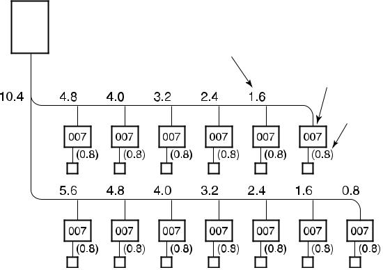
3.Basic system configuration
System legend (example) 8 hp system
• |
Max. number of indoor units: |
13 units |
• |
Indoor unit capacity code: |
Min. 4 |
|
|
Max. 10.8 |
Capacity code - total 10.4
Total number of units - 13
Outdoor unit
8HP
Capacity code over the branch (0.8 + 0.8 = 1.6)
Indoor unit designation
Capacity code
Indoor unit
Remote controller
13

10 hp system
• |
Max. number of indoor units: |
16 units |
• |
Indoor unit capacity code: |
Min. 5 |
|
|
Max. 13.5 |
Capacity code - total 12.8
Total number of units - 16
Outdoor unit
10HP
Indoor unit 


Remote 
 controller
14

20 hp system
• |
Max. number of indoor units: |
33 units |
• |
Indoor unit capacity code: |
Min. 10 |
|
|
Max. 27 |
Capacity code - total 26.75
Total number of units - 19
Outdoor unit
10HP 10HP
Indoor unit
Remote  controller
15

30 hp system
• |
Max. number of indoor units: |
48 units |
• |
Indoor unit capacity code: |
Min. 15 |
|
|
Max. 40.5 |
Capacity code - total 40
Total number of units - 28
Outdoor unit
10HP 10HP 10HP
Indoor unit
Remote controller
16

40 hp system
• |
Max. number of indoor units: |
48 units |
• |
Indoor unit capacity code: |
Min. 20 |
|
|
Max. 54 |
Capacity code - total 53.75
Total number of units - 32
Outdoor unit
10HP 10HP 10HP 10HP
Indoor unit
Remote 

 controller
17

48 hp system
• Max. number of indoor units: |
48 units |
|||||||||||||||||||
• Indoor unit capacity code: |
Min. 24 |
|||||||||||||||||||
|
|
|
|
|
|
|
|
|
|
|
|
Max. 64.8 |
||||||||
Capacity code - total 61.9 |
|
|
|
|
|
|
|
|
|
|||||||||||
Total number of units - 40 |
|
|
|
|
|
|
|
|
|
|||||||||||
|
|
|
|
|
|
|
Outdoor unit |
|
|
|
|
|
|
|
|
|
||||
|
|
|
|
|
|
|
|
|
|
|
|
|
|
|
|
|
|
|
|
|
|
|
|
|
|
|
|
|
|
|
|
|
|
|
|
|
|
|
|
|
|
|
|
|
|
|
|
|
|
|
|
|
|
|
|
|
|
|
|
|
|
|
|
|
|
|
|
|
|
|
|
|
|
|
|
|
|
|
|
|
|
|
|
|
|
|
|
|
|
|
|
|
|
|
|
|
|
|
|
|
|
|
|
|
|
|
|
|
|
|
|
|
|
|
|
|
|
|
|
|
|
|
|
|
|
|
|
|
|
|
|
|
|
|
|
|
|
|
|
|
|
|
|
|
|
|
|
|
|
|
|
|
|
|
|
|
|
|
|
|
|
|
|
|
|
|
|
|
|
|
|
|
|
|
|
|
|
|
|
|
|
|
|
|
|
|
|
|
|
|
|
|
|
|
|
|
|
|
|
|
|
|
|
|
|
|
|
|
|
|
|
|
|
|
|
|
|
|
|
|
|
|
|
|
|
|
|
|
|
|
|
|
|
|
|
|
|
|
|
|
|
|
|
|
|
|
|
|
|
|
|
|
|
|
|
|
|
|
|
|
|
|
|
|
|
|
|
|
|
|
|
|
|
|
|
|
|
|
|
|
|
|
|
|
|
|
|
|
|
|
|
|
|
|
|
|
|
|
|
|
|
|
|
|
|
|
|
|
|
|
|
|
|
|
|
|
|
|
|
|
|
|
|
|
|
|
|
|
|
|
|
|
|
|
|
|
|
|
|
|
|
|
|
|
|
|
|
|
|
|
|
|
|
|
|
|
Indoor unit 


Remote 


 controller
18

4.Equipment selection procedure
1. Selection flow chart
1. Determination of indoor air conditioning load
2. Preliminary selection of indoor units |
|
3. Preliminary selection of outdoor unit with indoor units
4. Capacity correction for piping length/height between indoor and outdoor units
|
|
|
|
|
|
|
|
|
|
|
|
|
|
|
|
|
|
|
|
|
|
|
|
|
|
|
|
|
|
|
|
5. Capacity correction based on indoor and outdoor temperature |
|
|
|
|
||||||||
|
|
|
|
|
|
|
|
|
|
|
|
|
|
|
|
|
|
|
|
|
|
|
|
|
|
|
|
|
No |
|
|
|
6. Validate preliminary selection of indoor units |
|
|
|
|
|||||||
|
|
|
|
|
|
|
|
|||||||
|
|
|
|
|
|
|
|
|
|
|
|
|
|
|
|
|
|
|
|
|
|
|
|
|
|
|
|
|
|
|
|
7. Confirmation of selection for indoor unit and outdoor units |
|
|
|
|
||||||||
|
|
|
|
|
|
|
|
|
|
|
|
|
|
|
|
|
|
|
|
|
|
|
|
|
|
|
|
|
|
|
|
|
|
|
|
End |
|
|
|
|
|
|
|
|
|
|
|
|
|
|
|
|
|
||||||
2. Indoor unit and outdoor unit combination |
|
|
|
|
|
|
|
|||||||
For indoor unit, the capacity code is decided for each model size. |
|
|
|
|
|
|
|
|||||||
|
|
|
|
|
|
|
|
|
|
|
|
|
|
|
Model size |
007 |
009 |
012 |
015 |
018 |
024 |
027 |
030 |
036 |
048 |
056 |
072 |
096 |
|
Cooling capacity, kW |
2.2 |
2.8 |
3.6 |
4.5 |
5.6 |
7.1 |
8.0 |
9.0 |
11.2 |
14.0 |
16.0 |
22.4 |
28.0 |
|
Capacity code |
0.8 |
1 |
1.25 |
1.7 |
2 |
2.5 |
3 |
3.2 |
4 |
5 |
6 |
8 |
10 |
|
Note: Model size: corresponding to Btu/h. Capacity code: corresponding to horsepower.
For outdoor unit, maximum number of connectable indoor units and total capacity code of indoor units are decided.
Outdoor unit |
Outdoor unit |
Capacity code |
Max. No. of |
Total indoor unit |
(cooling only) |
(heat pump) |
of outdoor unit |
indoor units |
capacity code |
MMY-MAP0501T8 |
MMY-MAP0501HT8 |
5 |
8 |
2.5 to 6.75 |
MMY-MAP0601T8 |
MMY-MAP0601HT8 |
6 |
10 |
3 to 8.1 |
MMY-MAP0801T8 |
MMY-MAP0801HT8 |
8 |
13 |
4 to 10.8 |
MMY-MAP1001T8 |
MMY-MAP1001HT8 |
10 |
16 |
5 to 13.5 |
MMY-MAP1201T8 |
MMY-MAP1201HT8 |
12 |
20 |
6 to 16.2 |
MMY-AP1401T8 |
MMY-AP1401HT8 |
14 |
23 |
7 to 18.9 |
MMY-AP1601T8 |
MMY-AP1601HT8 |
16 |
27 |
8 to 21.6 |
MMY-AP1801T8 |
MMY-AP1801HT8 |
18 |
30 |
9 to 24.3 |
MMY-AP2001T8 |
MMY-AP2001HT8 |
20 |
33 |
10 to 27.0 |
MMY-AP2201T8 |
MMY-AP2201HT8 |
22 |
37 |
11 to 29.7 |
MMY-AP2211T8 |
MMY-AP2211HT8 |
22 |
37 |
11 to 29.7 |
MMY-AP2401T8 |
MMY-AP2401HT8 |
24 |
40 |
12 to 32.4 |
MMY-AP2411T8 |
MMY-AP2411HT8 |
24 |
40 |
12 to 32.4 |
MMY-AP2601T8 |
MMY-AP2601HT8 |
26 |
43 |
13 to 35.1 |
MMY-AP2801T8 |
MMY-AP2801HT8 |
28 |
47 |
14 to 37.8 |
MMY-AP3001T8 |
MMY-AP3001HT8 |
30 |
48 |
15 to 40.5 |
MMY-AP3201T8 |
MMY-AP3201HT8 |
32 |
48 |
16 to 43.2 |
MMY-AP3211T8 |
MMY-AP3211HT8 |
32 |
48 |
16 to 43.2 |
MMY-AP3401T8 |
MMY-AP3401HT8 |
34 |
48 |
17 to 45.9 |
MMY-AP3411T8 |
MMY-AP3411HT8 |
34 |
48 |
17 to 45.9 |
MMY-AP3601T8 |
MMY-AP3601HT8 |
36 |
48 |
18 to 48.6 |
MMY-AP3611T8 |
MMY-AP3611HT8 |
36 |
48 |
18 to 48.6 |
MMY-AP3801T8 |
MMY-AP3801HT8 |
38 |
48 |
19 to 51.3 |
MMY-AP4001T8 |
MMY-AP4001HT8 |
40 |
48 |
20 to 54.0 |
MMY-AP4201T8 |
MMY-AP4201HT8 |
42 |
48 |
21 to 56.7 |
MMY-AP4401T8 |
MMY-AP4401HT8 |
44 |
48 |
22 to 59.4 |
MMY-AP4601T8 |
MMY-AP4601HT8 |
46 |
48 |
23 to 62.1 |
MMY-AP4801T8 |
MMY-AP4801HT8 |
48 |
48 |
24 to 64.8 |
50 to 135% of outdoor unit capacity 
19

3. Cooling/heating capacity characteristics
Cooling capacity calculation method:
Required cooling capacity = cooling capacity x factor (, , , , *1) kW
Indoor air wet bulb temperature vs. capacity correction value
Capacity correction value

Indoor air wet bulb temperature (°C)
Outdoor air dry bulb temperature vs. capacity correction value
Capacity correction value

Outdoor air dry bulb temperature (°C)
Air flow variation ratio of indoor unit vs. capacity correction (for ducted units only)
Capacity correction value


Air flow variation ratio (%)
*1 Outdoor unit capacity correction factor when total capacity of the indoor units is not equal to the outdoor unit capacity.
20
Connecting pipe length and lift difference between indoor and outdoor units vs. capacity correction value
Outdoor unit (5 to 44 hp)
Outdoor unit height H (m) |
Pipe length (equivalent length) L (m)
 Outdoor unit
|
Outdoor unit (46 to 48 hp) |
|
|
ho |
l’o |
H (m) |
|
|
height |
|
ha |
|
|
|
Outdoor unit |
hc |
hb |
|
||
|
|
L’ is the longest dimension of (l’o + l’a, l’o + l’b, l’o + l’c)
H = ho + (longest dimension of ha, hb and hc)
l’a |
|
l’b |
Indoor unit |
|
|
l’c |
|
Pipe length (equivalent length) L (m)
Correction of outdoor unit diversity
Correction (%)
Standard capacity ratio
Indoor unit total capacity ratio (%)
21

Heating capacity calculation method:
Required heating capacity = heating capacity x factor (, , , , *1, *2) kW
Indoor air dry bulb temperature vs. capacity correction value
Capacity correction value
Indoor air dry bulb temperature (°C)
Outdoor air wet bulb temperature vs. capacity correction value
Capacity correction value

Outdoor air wet bulb temperature (°C)
Air flow variation ratio of indoor unit vs. capacity correction (for ducted units only)
Capacity correction value
Air flow variation ratio (%)
*1 Outdoor unit capacity correction factor when total capacity of the indoor units is not equal to the outdoor unit capacity. *2 Refer to the capacity correction for frosting on the outdoor heat exchanger section on page 24.
22

Connecting pipe length and lift difference between indoor and outdoor units vs. capacity correction value
Outdoor unit (5 to 48 hp)
Outdoor unit height H (m) |
Pipe length (equivalent length) L (m)
 Outdoor unit
ho l’o
ha hb 
hc
L’ is the longest dimension of (l’o + l’a, l’o + l’b, l’o + l’c)
H = ho + (longest dimension of ha, hb and hc)
l’a
l’b
Indoor unit
l’c
Correction of outdoor unit diversity
Correction (%)
Standard capacity ratio
Indoor unit total capacity ratio (%)
23

Capacity correction for frosting on the outdoor heat exchanger (heating mode)
Correct the heating capacity when frost was found on the outdoor heat exchanger.
Heating capacity = Capacity after correction of outdoor unit × correction value of capacity resulting from frost (Capacity after correction of outdoor unit: Heating capacity calculated in the previous section.)
Capacity correction for frosting on the outdoor heat exchanger
Capacity correction value
Outdoor air wet bulb temperature (°C)
Capacity calculation for each indoor unit
Capacity for each indoor unit =
Capacity after correction of outdoor unit × Required standard capacity of indoor unit
Total value of standard indoor unit capacity
Operating temperature range
|
In cooling mode |
|
|
(°C) |
|
rangeUsable |
mode)down-pull(in |
temperaturebulbdry |
Continuous |
||
|
|
|
|
|
operating |
|
|
|
range |
|
|
Outdoor air |
|
|
|
Indoor air wet bulb temperature (°C)
Rated conditions
Cooling: Indoor air temperature 27°C db/19°C wb. Outdoor air temperature 35°C db.
Heating: Indoor air temperature 20°C db. Outdoor air temperature 7°C db/6°C wb.
In heating mode
(°C) |
|
|
|
Outdoor air wet bulb temperature |
Usable range |
(in warming-up mode) |
Continuous |
operating |
|||
range |
|||
|
Indoor air dry bulb temperature (°C)
The unit can be operated even if outdoor temperature falls to -20°C. However, the warranty only covers operation down to -15°C, as lower temperatures are outside the operating range.
When the outdoor air temperature falls to below -15°C, unit operation may reduce the product life.
24

Example of equipment selection
The following shows an example of equipment selection based upon a building model.
Fig. 1 - Overview of building model
Outside view |
Floor configuration |
Small meeting room
Executive rooms
Office rooms (Entire floor)
Office rooms
Stores |
Non-air conditioning zone
•Steel frame, reinforced concrete building, four floors above ground. Total floor area : 415 m²
Outdoor unit is installed on the roof.
•Indoor design conditions:
Cooling: 27.0/19.0°C db/wb. Heating: 20°C db
•Outdoor design conditions:
Cooling: 35°C db (standard condition). Heating: 3°C wb (standard condition: 6°C wb)
Selection criteria for each floor
1F: Outdoor unit capacity exactly matches the total indoor unit capacity.
Total indoor unit hp = Outdoor unit hp |
Indoor: 2.5 hp x 2 units + 3.2 hp + 2 hp = 10.2 hp |
|
Outdoor: 10 hp Same capacity |
2F: Outdoor unit capacity matches the potential total indoor unit capacity with the possibility of future extension.
Office rooms 2 and 3 are to be used as warehouses at first, so air conditioning is not necessary at present. However, there is a plan to convert them into offices, so an outdoor module with extra capacity is required. Piping/wiring are carried out. Indoor unit is not yet installed.
When the rooms are used as an office later, the indoor unit is installed.
3F: One indoor unit is connected to one outdoor unit.
The outdoor module should have sufficient capacity to cover the peak demand of the indoor unit connected.
4F: Consider the diversity factor and have the outdoor module match 135% of indoor unit capacity.
This is a typical matching of indoor/outdoor units for a Super MMS system.
•Total indoor unit hp > Outdoor unit hp
•Select each indoor unit based on individual peak room load.
Indoor: 2.5 hp + 2.5 hp + 2 hp + 2 hp (capacity difference in each room) + 1.3 hp =
10.3 hp (different capacity) 
 Outdoor: 8 hp (different capacity)
•The cooling load profile needs to be taken into consideration.
25

Procedure and result of equipment selection
1.Procedure of equipment selection
a.Calculate cooling for every room.
b.Select an indoor unit to match the cooling load for every room from the table on page 10.
c.Select the outdoor module to match the indoor units selected in point b. Select the outdoor modules based on the critical factors and the combination rule. Choose a tentative outdoor module that will match the indoor units, and check whether the selection agrees with the combination rule. Perform the capacity correction based on the pipe length, system lift, indoor set temperature, outdoor temperature.
Then, make sure the corrected system cooling capacity satisfies the cooling load.
2.Equipment selection and capacity check
|
Air conditioning load |
|
|
|
|
Equipment selection |
|
|
|
|
|
||||
|
Floor |
Room No. |
|
Indoor air conditioning load (kW) |
|
Indoor unit |
|
|
|
Outdoor unit |
|
|
|
||
|
|
|
|
|
|
|
|
Model |
|
Capacity (kW) |
Model |
Capacity (kW) |
|||
|
|
|
|
Cooling |
Heating |
|
MMU- |
|
Cooling |
Heating |
MMY |
Cooling |
Heating |
||
|
4F |
4-1 |
|
6.0 (16 o’clock) |
5.4 |
|
|
AP0241H |
7.1 |
8.0 |
AP2801HT8 |
78.5 |
88.0 |
||
|
|
4-2 |
|
5.2 (14 o’clock) |
4.2 |
|
|
AP0181H |
5.6 |
6.3 |
|
|
|
|
|
|
|
4-3 |
|
5.0 (14 o’clock) |
4.2 |
|
|
AP0181H |
5.6 |
6.3 |
|
|
|
|
|
|
|
4-4 |
|
3.2 (12 o’clock) |
2.7 |
|
|
AP0121H |
3.6 |
4.0 |
|
|
|
|
|
|
|
4-5 |
|
6.4 (10 o’clock) |
5.4 |
|
|
AP0241H |
7.1 |
8.0 |
|
|
|
|
|
|
3F |
3-1 |
|
12.7 |
12.0 |
|
|
AP0481H |
14.0 |
16.0 |
|
|
|
|
|
|
2F |
2-1 |
|
4.8 |
4.5 |
|
|
AP0181H |
5.6 |
6.3 |
|
|
|
|
|
|
|
2-2 |
|
4.6 |
4.8 |
|
|
AP0181H |
5.6 |
6.3 |
|
|
|
|
|
|
|
2-3 |
|
— |
— |
|
— |
|
— |
— |
|
|
|
|
|
|
1F |
1-1 |
|
6.5 |
6.0 |
|
|
AP0241H |
7.1 |
8.0 |
|
|
|
|
|
|
|
1-2 |
|
6.5 |
6.3 |
|
|
AP0241H |
7.1 |
8.0 |
|
|
|
|
|
|
|
1-3 |
|
7.2 |
7.0 |
|
|
AP0301H |
9.0 |
10.0 |
|
|
|
|
|
|
|
1-4 |
|
5.1 |
4.5 |
|
|
AP0181H |
5.6 |
6.3 |
|
|
|
|
|
|
Note: ( ): Peak occurrence time |
|
|
|
|
|
|
|
|
|
|
|
|
||
|
|
|
|
|
|
|
|
|
|
|
|
|
|
||
|
Piping distance |
|
|
|
Capacity correction |
Capacity check after correction |
|
||||||||
|
Floor |
Room No. |
|
Equivalent |
Height |
|
Pipe correction x |
|
|
Capacity (kW) |
|
Result |
|
||
|
|
|
|
length (m) |
difference (m) |
|
temp. correction |
|
|
|
|
|
|
|
|
|
|
|
|
|
|
|
Cooling |
Heating |
Cooling |
Heating |
|
|
|
||
|
4F |
4-1 |
|
43 |
12 |
|
0.920 |
0.957 |
6.5 |
6.9 |
|
Good |
|
||
|
|
4-2 |
|
|
|
|
x |
x |
5.2 |
5.4 |
|
|
|
||
|
|
4-3 |
|
|
|
|
1.0 |
1.0 |
|
5.2 |
5.4 |
|
|
|
|
|
|
4-4 |
|
|
|
|
x |
x |
3.3 |
3.5 |
|
|
|
||
|
|
4-5 |
|
|
|
|
1.0 |
0.95 |
6.5 |
6.9 |
|
|
|
||
|
3F |
3-1 |
|
|
|
|
= |
|
x |
12.9 |
13.8 |
|
|
|
|
2F |
2-1 |
|
|
|
|
0.920 |
0.95 |
5.2 |
5.4 |
|
|
|
|||
|
|
2-2 |
|
|
|
|
|
|
= |
|
5.2 |
5.4 |
|
|
|
|
|
2-3 |
|
|
|
|
|
|
0.864 |
— |
— |
|
|
|
|
|
1F |
1-1 |
|
|
|
|
|
|
|
|
6.5 |
6.9 |
|
|
|
|
|
1-2 |
|
|
|
|
|
|
|
|
6.5 |
6.9 |
|
|
|
|
|
1-3 |
|
|
|
|
|
|
|
|
8.3 |
8.6 |
|
|
|
|
|
1-4 |
|
|
|
|
|
|
|
|
5.2 |
5.4 |
|
|
|
26

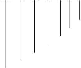
Example: Equipment selection based on system load profile
Since the five rooms on the 4th floor face different directions, their hourly cooling load profile will also be different. We select each indoor unit based on the individual room peak load. However, we need to use the total load profile on the 4th floor as a base to choose the outdoor module.
Load in each room
4-1
Load (kW)
Time
4-2
Load (kW)
Time |
4-3 |
Load (kW) |
Time |
4-4 |
Total load in all rooms of 4th floor
Total load (kW)
Time
1.The total load on the 4th floor is calculated by adding up the hourly cooling loads of the five rooms.
2.The maximum value of the total load is used to
select the outdoor module.
Load (kW)
Time
4-5
Load (kW)
Time
27
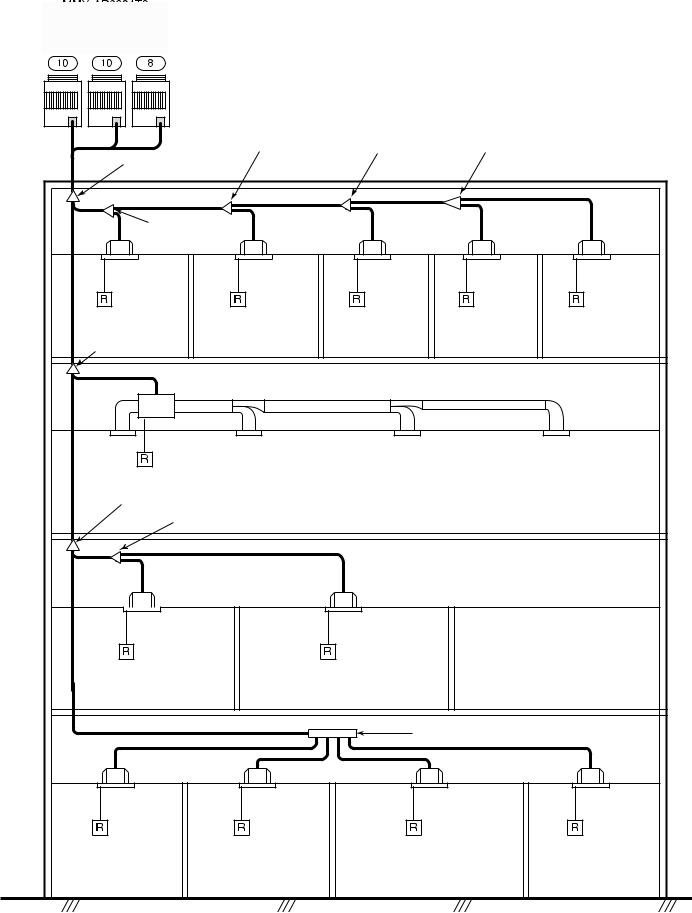
Schematic diagram
 MMY-AP2801T8
 MMY-AP2801HT8
Outdoor unit
|
|
3rd branching |
4th branching |
5th branching |
|
|
1st branching |
joint |
joint |
joint |
|
|
joint |
|
|
|
|
|
2nd branching |
|
|
|
|
|
joint |
|
|
|
|
|
Indoor unit |
Indoor unit |
Indoor unit |
Indoor unit |
Indoor unit |
|
MMU-AP0241H |
MMU-AP0181H |
MMU-AP0181H |
MMU-AP0121H |
MMU-AP0241H |
2nd branching |
|
|
|
|
|
joint |
4-1 |
4-2 |
4-3 |
4-4 |
4-5 |
|
|||||
|
|
|
|
|
3-5 |
|
Indoor unit |
|
|
|
|
|
MMD-AP0481H |
|
|
|
|
|
3rd branching |
|
|
|
|
|
joint |
|
|
|
|
|
4th branching |
|
|
|
|
|
joint |
|
|
|
|
|
Indoor unit |
|
Indoor unit |
|
|
|
MMU-AP0181H |
|
MMU-AP0181H |
|
|
|
|
|
|
No air conditioner |
|
|
2-1 |
|
|
2-2 |
2-3 |
|
|
|
Branching header |
|
|
|
Indoor unit |
Indoor unit |
|
Indoor unit |
Indoor unit |
|
MMU-AP0241H |
MMU-AP0241H |
|
MMU-AP0301H |
MMU-AP0181H |
|
1-1 |
1-2 |
|
1-3 |
1-4 |
28

5.Refrigerant piping design
1. Warnings on refrigerant leakage
Check of concentration limit
The room in which the air conditioner is to be installed requires a design that ensures that the concentration of refrigerant gas will not exceed a set limit if there is a leak.
Refrigerant R-410A which is used in the air conditioner is safe, without the toxicity or combustibility of ammonia, and is not restricted by laws that protect the ozone layer. However, since it contains more than air, it poses the risk of suffocation if its concentration should rise excessively. Suffocation from leakage of R-410A is almost nonexistent. With the recent increase in the number of high concentration buildings, however, the installation of multi air conditioner systems is on the increase because of the need for effective use of floor space, individual control, energy conservation by curtailing heat and carrying power, etc.
Most importantly, the multi air conditioner system is able to contain a large amount of refrigerant compared with conventional individual air conditioners. If a single unit of the multi air conditioner system is to be installed in a small room, select a suitable model and installation procedure so that if the refrigerant accidentally leaks out, its concentration does not reach the limit (and in the event of an emergency, measures can be made before injury can occur).
In a room where the concentration may exceed the limit, create an opening to adjacent rooms, or install mechanical ventilation combined with a gas leak detection device. The concentration is as given below.
Total amount of refrigerant (kg)
Min. volume of the indoor unit installed room (m³) ≤ Concentration limit (kg/m³)
The concentration limit of R-410A which is used in multi air conditioners is 0.3 kg/m³.
Note 1: If there are 2 or more refrigeration systems in a single refrigeration device, the amounts of refrigerant should be as charged in each independent device.
For the amount of charge in this example:
•The possible amount of leaked refrigerant gas in rooms A, B and C is 10 kg.
•The possible amount of leaked refrigerant gas in rooms D, E and F is 15 kg.
Note 2: The standards for minimum room volume are as follows:
(1) No partition (shaded portion)
e.g. charged |
Outdoor unit |
|
e.g. charged amount (15 kg) |
||
amount (10 kg) |
Room A Room B Room C Room D Room E Room F
Indoor unit
(2)When there is an effective opening with the adjacent room for ventilation of leaking refrigerant gas (opening without a door, or an opening 0.15% or larger than the respective floor spaces at the top or bottom of the door).
(3)If an indoor unit is installed in each partitioned room and the refrigerant piping is interconnected, the smallest room is the critical room. But when a mechanical ventilation device is installed in combination with a gas leak detector in the smallest room where the density limit is exceeded, the volume of the next smallest room is used.
Outdoor unit
 Refrigerant piping
 Indoor unit
Refrigerant piping
|
|
Outdoor unit |
|
Very |
|
Indoor unit |
|
small |
|
||
|
|
||
room |
|
|
|
Small |
Medium room |
Large room |
|
room |
|||
|
|
Mechanical ventilation device - gas leak detector
29

Note 3: The minimum indoor floor area compared with the amount of refrigerant is roughly as follows (when the ceiling is 2.7 m high):
2. Free branching system
m2 |
Range |
below |
the |
|
|
|
density |
limit of |
|
|
|
0.3 kg/m |
3 |
|
|
|
|
||
|
|
(countermeasures |
|
|
|
|
not needed) |
|
|
Min. indoor floor area |
|
|||
|
|
|
||
|
|
|
|
|
Range above the density limit of 0.3 kg/m3 (countermeasures needed
kg
Total refrigerant amount
Line branching system
Header branching system
Header branching after line branching Line branching after header branching
Header branching after header branching
The above five branching systems are available to increase significantly the flexibility of refrigerant piping design.
Line branching system
Header branching system

 Outdoor unit
Branching joint
Indoor unit
Remote  controller

 Outdoor unit
Branching header
Indoor unit

Remote controller
Header branching after line branching
Line branching after header branching
Header branching after header branching

 Outdoor unit
Branching joint
Branching header
Indoor unit
Remote 
 controller


 Outdoor unit
Branching header
Branching joint
Indoor unit 
Remote  controller
30
 Loading...