


1402241301R01
Modular Multi System
Outdoor
Installation Instructions
Air Conditioner – Multi Split Type System
Instructions d’Installation Extérieure
Climatiseur – Système de Type Multi Split
Außengerät
Installationsanleitung
Klimaanlage – Geteilte Multi-Bauweise
Exterior
Instrucciones de Instalación
Aire acondicionado – Sistema de Tipo Multi Split
Istruzioni per l’installazione dell’unità esterna
Condizionatore d’aria – Tipo Multi Split
Buiten
Installatievoorschriften
Airconditioning – Multi-delig Type Systeem
HFCR407C
GB
F
D
E
I
NL


Contents
Introduction . . . . . . . . . . . . . . . . . . . . . . . . . . . . . . . . . . . . . . . . . . . .4
Installation . . . . . . . . . . . . . . . . . . . . . . . . . . . . . . . . . . . . . . . . . . . . .9
Trial Operation . . . . . . . . . . . . . . . . . . . . . . . . . . . . . . . . . . . . . . . .38
Troubleshooting . . . . . . . . . . . . . . . . . . . . . . . . . . . . . . . . . . . . . . . .48
Environmental . . . . . . . . . . . . . . . . . . . . . . . . . . . . . . . . . . . . . . . . .64
GB
Passer à la page 65 pour lire le manuel d’installation en
F français.
D Die deutsche Montageanleitung finden Sie auf Seite 127.
EPor favor, vaya a la página 189 para seguir las instrucciones del manual de instalacíon en lengua española.
I Il manuale d’installazione italiano è a pagina 251.
NL Zie bladzijde 313 voor de Nederlandse Installatichandleiding.
3

|
Introduction |
|
|
Contents |
|
|
Precautions . . . . . . . . . . . . . . . . . . . . . . . . . . . . . . . . . . . . |
.5 |
|
Operating Conditions . . . . . . . . . . . . . . . . . . . . . . . . . . . . . |
.6 |
|
Components . . . . . . . . . . . . . . . . . . . . . . . . . . . . . . . . . . . . . |
7 |
GB |
Metric/Imperial pipe conversion . . . . . . . . . . . . . . . . . . . . . |
7 |
4

Introduction
Precautions
Please read these instructions carefully before starting the installation.
This equipment should only be installed by suitably trained operatives.
In all cases ensure safe working practice: Observe precautions for persons in the vicinity of the works.
Ensure that all local, national and international regulations are satisfied.
Check that the electrical specifications of the unit meet the requirements of the site.
Carefully unpack the equipment, check for damage or shortages. Please report any damage immediately.
These units comply with EC Directive:
73/23/EEC (Low Voltage Directive) and 89/336/EEC (Electro Magnetic Compatibility).
Accordingly, they are designated for use in commercial and industrial environments.
Avoid installation in the following locations:
Where the water drainage may cause a nuisance or a hazard when frozen.
Where there is a danger of flammable gas leakage.
Where there are high concentrations of oil.
Where the atmosphere contains an excess of salt (as in coastal areas). Special maintenance is required to maintain product design life.
Where the airflow from the outdoor unit may cause annoyance.
Where the operating noise of the outdoor unit may cause annoyance.
Where the foundation is not strong enough to fully withstand the weight of the outdoor unit.
Where strong winds may blow against the air inlet of the outdoor unit.
Precautions for R407C Systems
R407C outdoor units use synthetic oils which are extremely hygroscopic. Therefore ensure that the refrigerant system is NEVER exposed to air or any form of moisture.
Mineral oils are unsuitable for use in these units and may lead to premature system failure.
Use only equipment which is suitable for use with R407C. Never use equipment which has been used with R22.
R407C should only be charged from the service cylinder in the liquid phase. It is advisable to use a gauge manifold set equipped with a liquid sight glass fitted in the centre (entry) port.
GB
5
Introduction
Operating Conditions
Outdoor Temperature |
–5 ~ 43°C |
Cooling |
|
|
|
||
–15 ~ 21°C |
Heating |
||
|
|||
|
|
|
|
Room Temperature |
18 ~ 32°C |
Cooling |
|
15 ~ 29°C |
Heating |
||
|
|||
Room Humidity |
<80% |
Cooling |
|
|
|
|
GB
1. Allocation standard of Model name
OUTDOOR
MM–A0280HT
Modular Multi
INDOOR
|
|
|
|
|
|
|
|
|
|
|
|
|
|
|
|
|
|
|
|
|
|
|
|
|
|
|
|
|
|
|
A – Outdoor |
|
|
|
|
|
|
|
|
|
|
|||
|
|
|
|
|
|
0280 |
– 28.0kW (10HP) |
|
C – Cooling |
|
|
|
||
|
|
|
|
|
|
|
|
T – Inverter |
||||||
|
|
|
|
|
|
0224 |
– 22.4kW (8HP) |
|
|
|||||
|
|
|
|
|
|
|
H – Heating |
|
||||||
|
|
|
|
|
|
|
|
X – Fixed Speed |
||||||
|
|
|
|
|
|
0160 |
– 16.0kW (6HP) |
|
|
|||||
|
|
|
|
|
|
|
|
|
|
|||||
|
|
|
|
|
|
|
|
|
|
|
|
|||
|
|
|
|
|
|
|
|
|
|
|
|
|
|
|
MM–TU056
Modular Multi
|
|
|
|
|
|
|
|
|
|
|
|
|
|
|
B |
– Built-In Duct Type |
|
|
|
|
|
028 – 2.8kW (1HP) |
|||||
|
C (CR) – Ceiling Type (IR Remote) |
|
||||
|
|
042 – 4.2kW (1.5HP) |
||||
|
K (KR) – High Wall Type (IR Remote) |
|
||||
|
|
056 – 5.6kW (2HP) |
||||
|
N |
– Carcase Type |
|
|||
|
|
080 – 8.0kW (3HP) |
||||
|
S (SR) |
– Low Wall Type (IR Remote) |
|
|||
|
|
112 – 11.2kW (4HP) |
||||
|
SB |
– Built-In Slim Duct Type |
|
|||
|
|
140 – 14.0kW (5HP) |
||||
|
TU |
– 2 Way Cassette Type |
|
|||
|
|
|
|
|||
|
|
|
||||
|
U |
– 4 Way Cassette Type |
|
|
|
|
|
|
|
|
|
|
|
2. Range of combined units
No. of combined units |
: 1 to 5 units |
Capacity range |
: Equivalent to 14HP (0384kW type) to 46HP (1288kW) |
3.Restriction for combination units
(1)The Inverter Unit should have the maximum capacity among all units in that combination.
(2)The 6HP fixed-speed unit is available only with the combination of 14HP and 22HP. (It cannot be used for any other combination.)
4.Rated conditions
Cooling |
: Indoor air temperature 27°C DB/19°C WB |
|
Outdoor air temperature 35°C DB/25°C WB |
Heating |
: Indoor air temperature 21°C DB/15.5°C WB |
|
Outdoor air temperature 7°C DB/6° C WB |
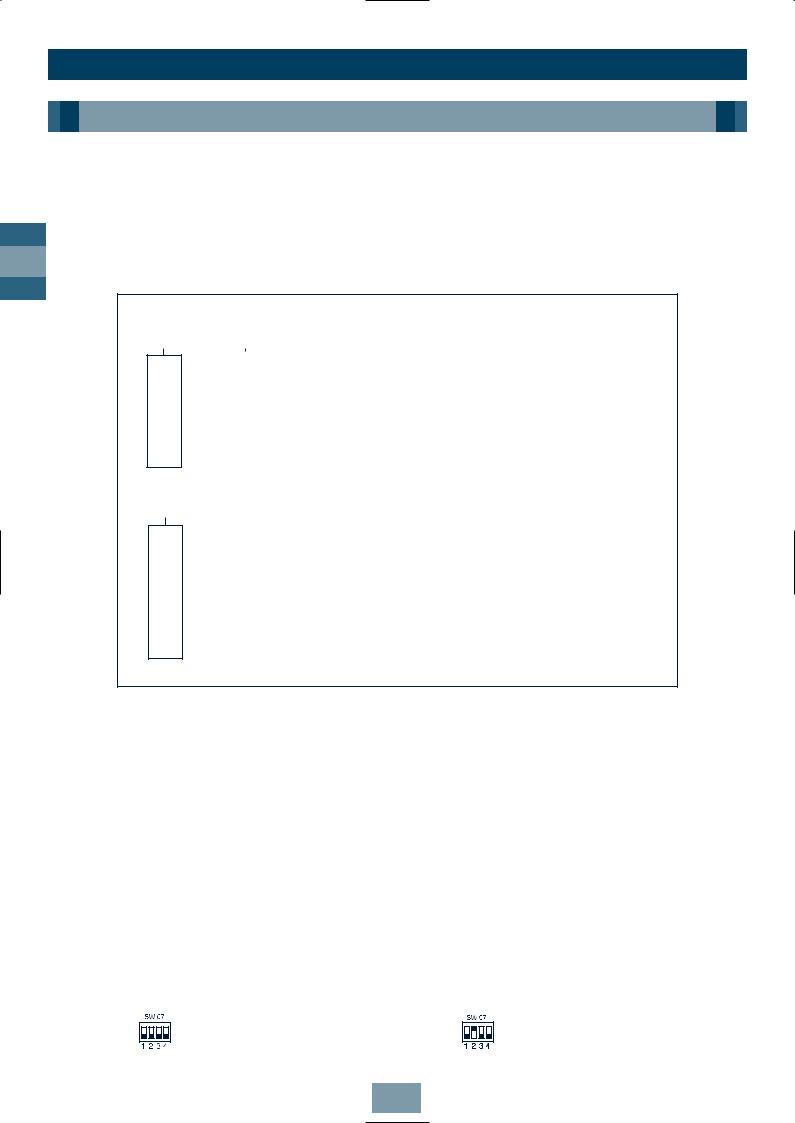
5. Mode Priority
This Outdoor Unit is set to operate with the Heating mode taking precidence. This precidence can be switched between Heat and Cool mode using the DIP switch 07 on the Outdoor Unit Interface PCB (MCC-1343-01) as follows:
ON OFF
Heat Priority (factory set)
ON OFF
Cool Priority
6

Introduction
Components
1. Outdoor Unit
|
Inverter unit |
|
Fixed-speed unit |
|
Appearance |
|||
Corresponding HP |
|
|
|
|
|
|
|
|
8HP |
10HP |
6HP |
|
8HP |
|
10HP |
|
|
|
|
|
|
|||||
|
|
|
|
|
|
|
||
Model name |
MM-A0224HT |
MM-A0280HT |
MM-A0160HX |
MM-A0224HX |
MM-A0280HX |
|
||
|
|
|
|
|
|
|
|
|
Cooling capacity (kW) |
22.4 |
28.0 |
16.0 |
|
22.4 |
|
28.0 |
|
|
|
|
|
|
|
|
|
|
Heating capacity (kW) |
25.0 |
31.5 |
18.0 |
|
25.0 |
|
31.5 |
|
|
|
|
|
|
|
|
|
|
GB
2. Outdoor Units (Combination of Outdoor Units)
Corresponding HP |
8HP |
10HP |
14HP |
16HP |
18HP |
20HP |
22HP |
24HP |
26HP |
28HP |
30HP |
32HP |
34HP |
36HP |
38HP |
40HP |
42HP |
44HP |
46HP |
||
|
|
|
|
|
|
|
|
|
|
|
|
|
|
|
|
|
|
|
|
||
Combined Model MM-A~HT |
0224 |
0280 |
0384 |
0440 |
0504 |
0560 |
0608 |
0672 |
0728 |
0784 |
0840 |
0896 |
0952 |
1008 |
1064 |
1120 |
1176 |
1232 |
1288 |
||
|
|
|
|
|
|
|
|
|
|
|
|
|
|
|
|
|
|
|
|
||
Cooling capacity (kW) |
22.4 |
28.0 |
38.4 |
44.8 |
50.4 |
56.0 |
60.8 |
67.2 |
72.8 |
78.4 |
84.0 |
89.6 |
95.2 |
100.8 |
106.4 |
112.0 |
117.6 |
123.2 |
128.8 |
||
|
|
|
|
|
|
|
|
|
|
|
|
|
|
|
|
|
|
|
|
|
|
|
Inverter unit |
8HP |
10HP |
8HP |
8HP |
10HP |
10HP |
8HP |
8HP |
10HP |
10HP |
10HP |
8HP |
10HP |
10HP |
10HP |
10HP |
10HP |
10HP |
10HP |
|
|
|
|
|
|
|
|
|
|
|
|
|
|
|
|
|
|
|
|
|
|
|
Combined |
|
— |
— |
6HP |
8HP |
8HP |
10HP |
8HP |
8HP |
8HP |
10HP |
10HP |
8HP |
8HP |
10HP |
10HP |
10HP |
8HP |
10HP |
10HP |
|
|
|
|
|
|
|
|
|
|
|
|
|
|
|
|
|
|
|
|
|
||
|
— |
— |
— |
— |
— |
— |
6HP |
8HP |
8HP |
8HP |
10HP |
8HP |
8HP |
8HP |
10HP |
10HP |
8HP |
8HP |
10HP |
||
outdoor |
Fixed- |
||||||||||||||||||||
units |
|
|
|
|
|
|
|
|
|
|
|
|
|
|
|
|
|
|
|
||
speed unit |
— |
— |
— |
— |
— |
— |
— |
— |
— |
— |
— |
8HP |
8HP |
8HP |
8HP |
10HP |
8HP |
8HP |
8HP |
||
|
|||||||||||||||||||||
|
|
||||||||||||||||||||
|
|
|
|
|
|
|
|
|
|
|
|
|
|
|
|
|
|
|
|
|
|
|
|
— |
— |
— |
— |
— |
— |
— |
— |
— |
— |
— |
— |
— |
— |
— |
— |
8HP |
8HP |
8HP |
|
|
|
|
|
|
|
|
|
|
|
|
|
|
|
|
|
|
|
|
|
|
|
No. of connectable |
13 |
16 |
16 |
18 |
18 |
20 |
22 |
24 |
26 |
28 |
30 |
32 |
34 |
36 |
38 |
40 |
40 |
40 |
40 |
||
indoor units |
|
||||||||||||||||||||
|
|
|
|
|
|
|
|
|
|
|
|
|
|
|
|
|
|
|
|
||
Min. HP Connection |
4 |
5 |
7 |
8 |
9 |
10 |
11 |
12 |
13 |
14 |
15 |
16 |
17 |
18 |
19 |
20 |
21 |
22 |
23 |
||
|
|
|
|
|
|
|
|
|
|
|
|
|
|
|
|
|
|
|
|
||
Max. HP Connection |
10.8 |
13.5 |
18.9 |
21.6 |
24.3 |
27 |
29.7 |
32.4 |
35.1 |
37.8 |
40.5 |
43.2 |
45.9 |
48.6 |
51.3 |
54 |
56.7 |
59.4 |
62.1 |
||
|
|
|
|
|
|
|
|
|
|
|
|
|
|
|
|
|
|
|
|
|
|
Metric/Imperial pipe conversion
Diameter (mm) |
6.4 |
9.5 |
12.7 |
15.9 |
19.0 |
22.0 |
28.6 |
34.9 |
41.3 |
54.1 |
|
|
|
|
|
|
|
|
|
|
|
Nominal Diameter (inch) |
1/4 |
3/8 |
1/2 |
5/8 |
3/4 |
7/8 |
1 1/8 |
1 3/8 |
1 5/8 |
2 1/8 |
|
|
|
|
|
|
|
|
|
|
|
Note: 1.0MPaG = 10.2kgf/cm2G
7

Introduction
Components
3. Indoor Unit
GB
Type |
Appearance |
Model name |
Capacity code/ |
Cooling Capacity |
Heating Capacity |
|
|
|
HP |
(kW) |
(kW) |
4 Way Cassette |
|
MM-U056 |
2 |
5.6 |
6.4 |
|
MM-U080 |
3 |
8.0 |
9.6 |
|
Type ‘U’ |
|
||||
|
MM-U112 |
4 |
11.2 |
12.8 |
|
|
|
||||
|
|
MM-U140 |
5 |
14.0 |
15.8 |
|
|
|
|
|
|
2 Way Cassette |
|
MM-TU028 |
1 |
2.8 |
3.2 |
Type ‘TU’ |
|
MM-TU042 |
1.5 |
4.2 |
4.8 |
|
|
MM-TU056 |
2 |
5.6 |
6.4 |
|
|
|
|
|
|
Built-In Slim |
|
|
|
|
|
Duct Type ‘SB’ |
|
MM-SB028 |
1 |
2.8 |
3.2 |
|
|
|
|
|
|
Built-In Duct, |
|
MM-B056 |
2 |
5.6 |
6.4 |
|
MM-B080 |
3 |
8.0 |
9.6 |
|
Type ‘B’ |
|
||||
|
MM-B112 |
4 |
11.2 |
12.8 |
|
|
|
||||
|
|
MM-B140 |
5 |
14.0 |
15.8 |
|
|
|
|
|
|
|
|
MM-C/CR042 |
1.5 |
4.2 |
4.8 |
Ceiling |
|
MM-C/CR056 |
2 |
5.6 |
6.4 |
Type ‘C’ |
|
MM-C/CR080 |
3 |
8.0 |
9.6 |
|
|
MM-C/CR112 |
4 |
11.2 |
12.8 |
|
|
MM-C/CR140 |
5 |
14.0 |
15.8 |
|
|
|
|
|
|
High Wall |
|
MM-K/KR042 |
1.5 |
4.2 |
4.8 |
|
MM-K/KR056 |
2 |
5.6 |
6.4 |
|
Type ‘K’ |
|
||||
|
MM-K/KR080 |
3 |
8.0 |
9.6 |
|
|
|
||||
|
|
|
|
|
|
Carcase |
|
MM-N028 |
1 |
2.8 |
3.2 |
|
MM-N042 |
1.5 |
4.2 |
4.8 |
|
Type ‘N’ |
|
||||
|
MM-N056 |
2 |
5.6 |
6.4 |
|
|
|
||||
|
|
MM-N080 |
3 |
8.0 |
9.6 |
|
|
|
|
|
|
Low Wall |
|
MM-S/SR056 |
2 |
5.6 |
6.4 |
Type ‘S’ |
|
||||
|
MM-S/SR080 |
3 |
8.0 |
9.6 |
|
|
|
||||
|
|
|
|
|
|
8

Installation
Contents
Outdoor Unit
Transportation of the Outdoor Unit . . . . . . . . . . . . . . . . . . . . . . . . . . |
.10 |
|
|
Installation of Outdoor Unit . . . . . . . . . . . . . . . . . . . . . . . . . . . . . . . . . |
11 |
|
|
Dimensional Drawings Outdoor Unit |
12 |
|
|
|
|||
Dimensional Drawings Two Units Connected |
13 |
|
|
GB |
|||
Dimensional Drawings Three Units Connected |
14 |
||
|
|||
|
|||
Dimensional Drawings Four Units Connected . . . . . . . . . . . . . . . . . . . . |
15 |
|
|
|
|||
Dimensional Drawings Five Units Connected . . . . . . . . . . . . . . . . . . . . |
16 |
|
|
Multiple Installation on the Rooftop . . . . . . . . . . . . . . . . . . . . . . . . . . . |
17 |
|
Piping
Free Branching System . . . . . . . . . . . . . . . . . . . . . . . . . . . . . . . . . . . . .19 Connecting Refrigerant Pipes . . . . . . . . . . . . . . . . . . . . . . . . . . . . . . . .20 Permissible Length/Height Separation of Refrigerant Piping . . . . . . . .21 Selection of Refrigerant Piping and Charge Requirement . . . . . . . . . .22 Branch Headers/Branch Joints (Accessories) . . . . . . . . . . . . . . . . . . . . .24 Branch Header/T-shape Branch Joint . . . . . . . . . . . . . . . . . . . . . . . . . .25 Connecting the Branching Kit/Y-shape Branching Joint . . . . . . . . . . . .26 Heat Insulating the Branching Pipes/Branching Header . . . . . . . . . . .27 T-shape Branching Joint – to Connect Outdoor Units . . . . . . . . . . . . . .29 Installation of Gas/Liquid Branching Pipes . . . . . . . . . . . . . . . . . . . . . .30 Airtight Test . . . . . . . . . . . . . . . . . . . . . . . . . . . . . . . . . . . . . . . . . . . . .31 Leak Position Check/Air Purge . . . . . . . . . . . . . . . . . . . . . . . . . . . . . . .32 Calculating the Additional Refrigerant Required . . . . . . . . . . . . . . . . .33 Additional Charge Amounts . . . . . . . . . . . . . . . . . . . . . . . . . . . . . . . . .34
Wiring
General/Wiring System Overview . . . . . . . . . . . . . . . . . . . . . . . . . . . .35
Connecting Power Source Cable/Control Cable . . . . . . . . . . . . . . . . . .36
Control Wiring Overview . . . . . . . . . . . . . . . . . . . . . . . . . . . . . . . . . . .37
9
Installation
Outdoor Unit
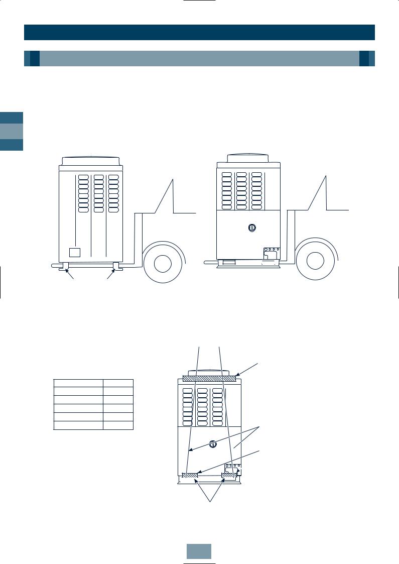
Transportation of the Outdoor Unit
Fork Lift
•Front Access – insert the forks into the slots on the fixing legs.
•Side Access – see diagram.
GB
Front Access |
Side Access |
Fork lift
Fixing Leg
Crane
•Check the suitability of the lifting rope (see table).
•Secure lifting rope through transportation slot.
•Protect the unit where rope contact could scratch or deform it.
Fork lift/ Hand Truck
Model Weight
MM-A0280HT 284.0kg
MM-A0224HT 282.0kg
MM-A0280HX 280.0kg
MM-A0224HX 278.0kg
MM-A0160HX 204.0kg
Protection
Rope

 Protection
Transportation Slots
10
Installation
Outdoor Unit
Installation of Outdoor Unit
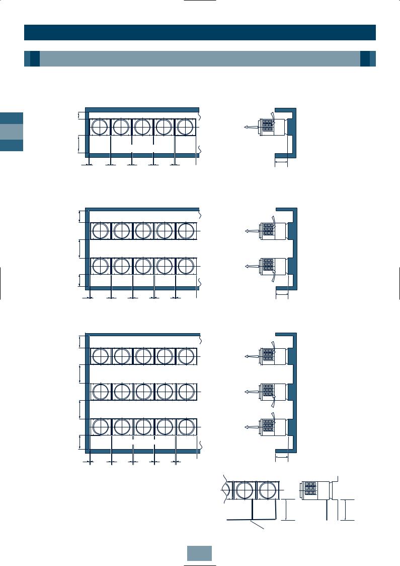
1.Align the outdoor units at intervals of 20mm or more.
Fix the outdoor units with M12 anchor bolts. (4 positions per unit.)
Anchor bolt with 20mm length is suitable.
20mm
≥ 20mm |
≥ 20mm |
GB
M12 anchor bolt,
4 positions per unit
• Anchor bolt pitch is as shown in the following figure.
700mm ≥ 310mm 700mm ≥ 310mm 700mm
755mm
15 x 20mm slot
•However, the equivalent pipe length between the nearest outdoor unit and farthest outdoor unit of the refrigerating cycle system should not exceed 20m.
2.When routing the refrigerant piping through the base, the fixing height of the base (two-divided foundations) must be 500m or more.
≥ 500mm
 Refrigerant Piping
3. Correct foundation mounts for supporting the Outdoor unit:


Note: The leading outdoor unit to be connected to the main refrigerant piping for the indoor units must be an inverter unit.
11
Installation
Outdoor Unit
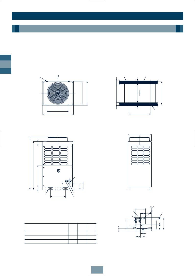
Dimensional Drawings
Outdoor Unit
GB
Model Name:
MM-A0280HT, MM-A0224HT, MM-A0280HX, MM-A0224HX, MM-A0160HX
|
|
|
|
Grounding part |
|
|
|
|
4-15 x 20 (Slot) |
|
|
|
of bottom plate |
|
|
Base |
|
|
|
|
|
80 |
|
|
||
|
|
|
|
|
|
|
||
|
|
|
|
100 610 100 |
|
|
|
|
Fixing bolt pitch |
755 |
790 |
(including fixed leg) |
630 |
|
755 |
Fixing bolt pitch |
|
Fixing bolt pitch |
|
|
|
|
80 |
|
|
|
700 |
|
|
|
|
|
|
Base |
|
990 |
|
|
|
|
|
700 |
|
|
|
|
|
|
|
|
|
Fixing bolt pitch
Base bolt position
750
90
1700 |
1560 |
700 |
|
Refrigerant pipe connecting port |
|
|
(Gas side) braze connection (ØA) |
||
88 |
245 |
190 |
235 |
2-60 x 150 Slot |
|
Refrigerant pipe connecting port |
|
|
|
|
|
|
|||
500 |
(Liquid side) flare connection (ØB) |
|
|
|
|
|
|
||||
(for transport) |
(Slot pitch) |
Balance pipe connecting |
|
|
|
|
Refrigerant pipe |
||||
|
|
|
|
|
|||||||
|
|
port flare connection (ØC) |
Refrigerant pipe |
(knock out) |
|||||||
|
|
connecting port |
|||||||||
|
|
|
|
|
|||||||
Note: All dimensions in (mm) |
|
|
|
connecting port |
173 |
|
(Gas side) |
||||
|
|
|
(Liquid side) |
|
|
||||||
|
|
|
|
60 |
115 |
|
|
(knock out) |
|||
|
|
|
|
|
Balance pipe |
|
|
|
|||
|
|
|
|
|
|
|
|
|
|
|
|
|
|
|
|
|
connecting port |
|
|
|
64 125 |
|
|
Model |
|
ØA |
ØB |
ØC |
145 |
130 |
|
|
140 |
170 |
|
|
|
|
|
|
|
|
|||||
|
|
|
|
|
|
|
|
||||
|
mm |
mm |
mm |
|
|
|
|
|
|
|
|
|
|
|
|
|
|
|
|
|
|||
MM-A0280HT, MM-A0280HX |
28.6 |
12.7 |
9.52 |
|
|
|
20 |
|
|
|
|
|
|
65 35 |
|
|
|
|
|||||
|
|
|
|
|
|
|
|
|
|
|
|
MM-A0224HT, MM-A0224HX 22.2 12.7 9.52
MM-A0160HX |
22.2 9.52 9.52 |
Details of piping |
|
connections |
|||
|
|
12

Installation
Outdoor Unit
Dimensional Drawings
Two Units Connected
Model Name:
MM-A0384HT, MM-A0440HT, MM-A0504HT, MM-A0560HT
|
≥ 20 |
|
|
|
|
8-15 x 20 (Slot) |
|
|
|
|
750 |
755 Fixing bolt pitch |
790 |
(including fixed leg) |
700 |
700 |
|
|
|
Fixing bolt pitch |
Fixing bolt pitch |
|
|
|
990 |
990 |
|
|
|
1 |
2 |
|
|
|
GB
90
1700 |
1560 |
88 700
|
|
2000 |
|
300 |
(Rear side) |
|
|
≥ |
|
|
1550≥ |
≥ |
10 |
|
|
|
|
||
≥ 500 |
|
≥ 10 |
|
|
≥ 20 |
|
|
|
side) |
≥ 2020 |
|
|
(Front |
|
|
|
No. |
Name |
1 |
Outdoor Unit (Inverter type) |
2 |
Outdoor Unit (Fixed-speed type) |
Note: All dimensions in (mm)
13

Installation
Outdoor Unit
Dimensional Drawings
Three Units Connected
GB
Model Name:
MM-A0608HT, MM-A0672HT, MM-A0728HT, MM-A0784HT, MM-A0840HT
|
≥ 20 |
|
≥ 20 |
12-15 x 20 (Slot) |
|
|
|
|
|
|
|
|
|
|
|
|
|
|
|
750 |
755 Fixing bolt pitch |
790 |
(including fixed leg) |
700 |
310 |
700 |
310 |
700 |
|
|
|
Fixing bolt pitch |
Fixing bolt pitch |
Fixing bolt pitch |
|
|
|
||
990 |
|
990 |
|
990 |
|
|
|
1 |
|
2 |
|
3 |
|
|
|
90
1700 |
1560 |
|
700 |
|
88 |
300 |
(Rear side) |
|
≥ |
|
1550≥ |
≥ 10 |
|
|
|
|
|
≥ 500 |
|
≥ 10 |
≥ 20 |
≥ 20 |
side) |
≥ 3030 |
|
|
||||
(Front |
|
|
|||||
|
|
|
|
|
|
|
|
|
|
|
|
|
|
|
|
|
|
|
|
|
|
|
|
|
|
|
No. |
Name |
|||
Note: All dimensions in (mm) |
|
|
|
1 |
|
Outdoor Unit (Inverter type) |
|
|
|
|
2 |
|
Outdoor Unit (Fixed-speed type 1) |
|
|
|
|
|
|
|
|
||
|
|
|
|
3 |
|
Outdoor Unit (Fixed-speed type 2) |
|
|
|
|
|
|
|
|
|
14
Installation
Outdoor Unit
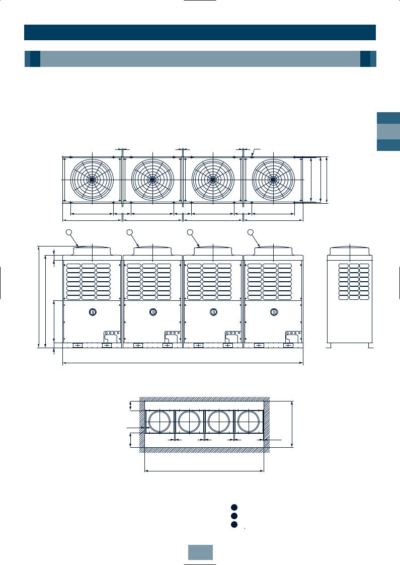
Dimensional Drawings
Four Units Connected
Model Name:
MM-A0896HT, MM-A0952HT, MM-A1008HT, MM-A1064HT, MM-A1120HT
|
|
|
≥ 20 |
|
≥ 20 |
|
≥ 20 |
16 - 15 x 20 (Slot) |
|
|
|
|
|
|
|
|
|
|
|
|
|
|
|
|
|
|
|
|
|
|
|
750 |
755 Fixing bolt pitch |
790 |
(including fixed leg) |
|
|
700 |
310 |
700 |
310 |
700 |
310 |
700 |
|
|
|
|
|
Fixing bolt pitch |
Fixing bolt pitch |
Fixing bolt pitch |
Fixing bolt pitch |
|
|
|
|||
|
|
|
|
|
|
|
|
||||
|
|
990 |
|
990 |
|
990 |
|
990 |
|
|
|
|
1 |
|
2 |
|
3 |
|
4 |
|
|
|
|
|
90 |
|
|
|
|
|
|
|
|
|
|
1700 |
1560 |
|
|
|
|
|
|
|
|
|
|
|
700 |
|
|
|
|
|
|
|
|
|
|
|
88 |
|
|
|
|
|
|
|
|
|
|
|
|
|
|
|
4020 |
|
|
|
|
|
|
|
|
|
300 |
(Rear side) |
|
|
|
|
|
|
|
|
|
|
≥ |
|
|
|
|
|
|
|
|
≥ 10 |
|
|
1550≥ |
|
|
|
|
≥ 500 |
|
|
≥ 10 |
≥ 20 |
≥ 20 |
≥ 20 |
|
side) |
|
|
|
(Front |
|
≥ 4040 |
|
|
|
|
|
No. |
Name |
|||
|
|
1 |
|
Outdoor Unit (Inverter type) |
|
Note: All dimensions in (mm) |
|
2 |
|
Outdoor Unit (Fixed-speed type 1) |
|
|
|
|
Outdoor Unit (Fixed-speed type 2) |
|
|
|
|
3 |
|
|
|
|
|
|
|
||
|
|
4 |
|
Outdoor Unit (Fixed-speed type 3) |
|
|
|
|
|
|
|
GB
15

Installation
Outdoor Unit
Dimensional Drawings
Five Units Connected
|
Model Name: |
|
|
|
|
|
|
|
|
|
|
|
GB |
MM-A1176HT, MM-A1232HT, MM-A1288HT |
|
|
|
|
|
|
|
||||
|
|
≥ 20 |
|
≥ 20 |
|
≥ 20 |
|
≥ 20 |
20 - 15 x 20 (Slot) |
|
|
|
|
|
|
|
|
|
|
|
|
|
|
|
|
|
|
|
|
|
|
|
|
|
700 |
755 Fixing bolt pitch |
790 |
(including fixed leg) |
|
700 |
310 |
700 |
310 |
700 |
310 |
700 |
310 |
700 |
|
|
|
|
Fixing bolt pitch |
|
Fixing bolt pitch |
|
Fixing bolt pitch |
|
Fixing bolt pitch |
|
Fixing bolt pitch |
|
|
|
|
990 |
|
990 |
|
990 |
|
990 |
|
990 |
|
|
|
|
1 |
|
2 |
|
3 |
|
4 |
|
5 |
|
|
|
|
90 |
|
|
|
|
|
|
|
|
|
|
|
1700 |
1560 |
|
|
|
|
|
|
|
|
|
|
|
|
700 |
|
|
|
|
|
|
|
|
|
|
|
|
88 |
|
|
|
|
|
|
|
|
|
|
|
|
5030 |
|
|
|
300 |
(Rear side) |
|
|
|
≥ |
|
|
|
|
≥ 10 |
|
|
1550 |
|
|
|
|
|
|
500 |
|
|
|
≥ 10 |
|
|
|
≥ |
|
≥ |
≥ 20 |
≥ 20 |
≥ 20 |
≥ 20 |
side) |
|
(Front |
≥ 5050 |
|
|
|
|
|
|
|
|
|
|
|
|
|
|
|
|
No. |
Name |
|||
|
|
|
|
|
|||||
|
|
|
|
|
|
1 |
|
Outdoor Unit (Inverter type) |
|
|
|
|
|
|
|
2 |
|
Outdoor Unit (Fixed-speed type 1) |
|
Note: All dimensions in (mm) |
|
3 |
|
Outdoor Unit (Fixed-speed type 2) |
|
||||
|
4 |
|
Outdoor Unit (Fixed-speed type 3) |
|
|||||
|
|
|
|
|
|
|
|
||
|
|
|
|
|
|
5 |
|
Outdoor Unit (Fixed-speed type 4) |
|
|
|
|
|
|
|
|
|
|
|
16

Installation
Outdoor Unit
Multiple Installation on the Rooftop
When the Outer Wall is Higher than the Outdoor Unit
If a hole can be made in the wall:
≥ 300 |
|
|
|
|
|
≥ 600 |
|
(Front side) |
|
|
|
≥ 10 |
≥ 20 |
≥ 20 |
≥ 20 |
≥ 20 |
|
|
|
|
|
|
HD |
1. Set an aperture ratio so that suction air volume |
|
||||
Vs from the hole becomes 1.5m/s or less. |
H |
||||
|
|
|
|
|
|
2. Height of discharge duct: HD = H - h. |
|
h |
|||
If a hole cannot be made:
≥ 300 |
|
|
|
|
≥ 600 |
|
(Front side) |
|
|
≥ 10 |
≥ 20 |
≥ 20 |
≥ 20 |
≥ 20 |
GB
Discharge duct
Vs |
1000 ≥ |
Hole in wall
1.Set a base with 500 to 1,000mm height.
2.Height of discharge duct: HD = H - h.
Note: All dimensions in (mm)
Discharge duct
H
h
Base
500 – 1000
17
GB
Installation
Outdoor Unit
When the Outer Wall is Lower than the Outdoor Unit
1-line installation |
|
|
|
|
|
≥ 300 |
|
|
|
|
|
≥ 500 |
|
(Front side) |
|
|
|
≥ 10 |
≥ 20 |
≥ 20 |
≥ 20 |
≥ 20 |
≤ 800 |
|
|
|
|
|
|
2-parallel lines installation
|
≥ 300 |
|
|
600 |
1000) |
(Front side) |
|
≥ |
≥ |
||
|
|||
|
*( |
|
|
≥ 300 |
|
|
|
|
|
|
≥ 10 |
≥ 20 |
≥ 20 |
≥ 20 |
≥ 20 |
≤ 800 |
|
|
|
|
|
|
|
3-parallel lines installation |
|
|
|
|||
|
≥ 300 |
|
|
|
|
|
≥ 600 |
≥ 1000) |
|
(Front side) |
|
|
|
|
*( |
|
|
|
|
|
|
≥ 600 |
|
|
|
|
|
|
500≥ |
|
(Front side) |
|
|
|
|
|
|
|
|
||
|
≥ 10 |
≥ 20 |
≥ 20 |
≥ 20 |
≥ 20 |
≤ 800 |
|
|
|||||
*When refrigerant piping is routed from the front |
|
|
of the unit, distance between Outdoor Unit and |
|
|
Connecting piping must be 500mm or more. |
≥ 500 |
≥ 500 |
Note: All dimensions in (mm) |
Connecting Piping |
Piping |
|
18

Installation
Piping
Free Branching System
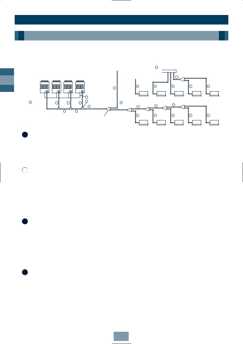
The following five branching systems are available to increase the flexibility of refrigerant piping design.
1
system
2Header branching system
3Header branching system after line branching
4Line branching system after header branching
5Header branching system after header branching
GB
Outdoor units
Indoor
units

 Remote
 controller
Outdoor units
Branching header
Indoor
units

 Remote controller

Outdoor units
Branching joint
Branching header
Indoor
units

 Remote
  controller

 Outdoor units
Branching header
Branching joint
Indoor units

 Remote
 controller
19
Installation
Piping
WARNING!
During installation – if the refrigerant gas leaks, ventilate the room. After installation – check for gas leakages.
If refrigerant gas comes into contact with fire – noxious gas may result!
GB
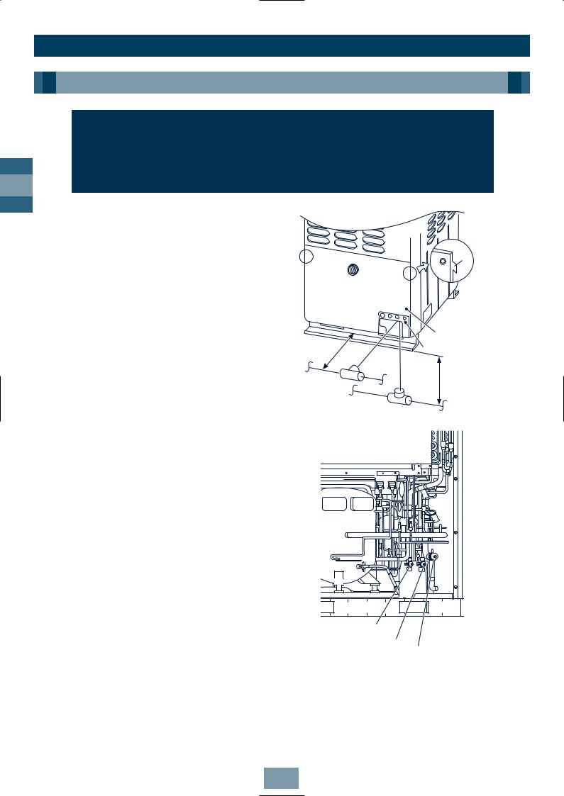
Connecting Refrigerant Pipes
1.To access the refrigerant piping connections and electrical wiring terminals, remove the 7xM5 securing bolts in the front panel. To remove the panel, lift it up and away from its hanging tabs – See diagram.
2.The refrigerant pipes can be routed forwards, downwards or sideways.
3.If the pipes are routed forwards, make sure they exit through the Piping/Wiring Panel – (remove knock out section) and allow at least 500mm between the Outdoor Unit and the main pipe connecting it to the Indoor Unit. This is for servicing access. (Replacing the compressor, for example, requires a space of at least 500mm.)
4.If the pipes are routed downwards, remove the knockout section in the baseplate of the Outdoor Unit. This will enable access. They can then be connected to the left or right, or the rear side. (Leading pipe of the balancing should be within 4m.)
Notes:
1.When brazing, use nitrogen. This prevents internal oxidisation of the pipes.
2.Always use clean new pipe, and ensure it is not contaminated by water or dust.
3.Always use a double spanner on the flare nut – and tighten to the specified torque: (see table).
Note: All dimensions in (mm)
Tab
Front panel
Piping/Wiring Panel
≥ |
500 |
4m |
|
||
|
|
|
Pipes routed |
Within |
|
|
||
forward |
|
|
|
|
Pipes routed downwards |
Valve at balance side (oil)
Valve at liquid side
Valve at gas side
Connecting pipe |
Tightening |
Re-tightening |
|
outer dia. (mm) |
torque (Nm) |
torque (Nm) |
|
|
|
|
|
Ø6.4 |
11.8 (1.2kgf m) |
13.7 |
(1.4kgf m) |
Ø9.5 |
24.5 (2.5kgf m) |
29.4 |
(3.0kgf m) |
Ø12.7 |
49.0 (5.0kgf m) |
53.9 |
(5.5kgf m) |
Ø15.9 |
78.4 (8.0kgf m) |
98.0 (10.0kgf m) |
|
Ø19.0 |
98.0 (10.0kgf m) |
117.7 |
(12.0kgf m) |
20
Installation
Piping
Permissible Length/Height Separation of Refrigerant Piping
|
|
|
|
|
|
|
|
|
|
|
|
|
|
|
|
|
|
|
|
|
|
|
|
|
|
|
|
|
|
|
Fixed-speed |
|
|
|
|
|
|
|
|
|
|
|
|
|
|
|
|
|
|
|
|
|
|
|
|||||||
|
|
|
|
|
|
|
|
|
|
|
|
|
|
|
|
|
|
|
|
|
|
|
|
|
|
|
|
|
|
|
|
|
|
|
|
|
|
|
|
|
|
|
|
|
|
|
|
|
|
|
|
|
|
||||||||
|
|
|
|
|
|
|
|
|
|
|
|
|
|
|
|
|
|
|
|
|
|
|
|
|
|
|
|
|
|
|
Unit n |
|
|
|
|
|
|
<Ex. 1> |
|
|
|
|
|
<Ex. 2> |
|
|
|
|
|
||||||||||||
|
|
|
|
|
|
|
|
|
|
|
|
|
|
|
|
|
|
|
|
|
|
|
|
|
|
(d) |
|
|
|
|
|
|
|
|
|
|
Fixed- |
|
Fixed- |
|
|
|
|
|
Fixed- |
Fixed- |
|||||||||||||||
|
|
|
|
|
|
|
|
|
|
|
|
|
|
|
|
|
|
|
|
|
|
|
|
|
|
|
|
|
|
|
|
|
|
|
|
|
|
|
|
|
|
|
|
|
|||||||||||||||||
|
|
|
|
|
|
|
|
|
|
|
|
|
|
Fixed- |
|
Fixed- |
|
|
|
|
|
|
|
|
|
|
Inverter |
Inverter |
|||||||||||||||||||||||||||||||||
|
|
|
|
|
|
Inverter |
|
speed |
|
speed |
|
|
|
|
|
|
|
|
|
|
speed |
|
speed |
speed |
speed |
||||||||||||||||||||||||||||||||||||
Height |
|
|
|
|
|
|
Unit |
|
|
Unit 1 |
|
Unit 2 |
Connecting |
|
|
|
|
|
|
Unit |
|
|
Unit 1 |
|
Unit 2 |
|
Unit |
|
Unit |
1 |
Unit |
2 |
|||||||||||||||||||||||||||||
difference |
|
Outdoor |
|
|
|
|
|
|
|
|
|
|
|
|
|
|
|
|
|
|
|
|
|
|
|
|
|
|
|
|
|
|
|
|
|
|
|
|
|
|
|
|
|
|
|
|
|
|
|
|
|
|
|
|
|||||||
|
|
|
|
|
|
|
|
|
|
|
|
|
|
|
|
|
|
|
|
|
|
|
|
|
|
|
|
|
|
|
|
|
|
|
|
|
|
|
|
|
|
|
|
|
|
|
|
|
|
|
|
|
|||||||||
between |
|
Unit |
|
|
|
|
|
|
|
|
|
|
|
|
|
|
|
|
|
|
piping of |
|
|
|
|
|
|
|
|
|
|
|
|
|
|
|
|
|
|
|
|
|
|
|
|
|
|
|
|
|
|
|
|
|
|||||||
|
|
|
|
|
|
|
|
|
|
|
|
|
|
|
|
|
|
|
Outdoor |
|
|
|
|
|
|
|
|
|
|
|
|
|
|
|
|
|
|
|
|
|
|
|
|
|
|
|
|
|
|
|
|
|
|||||||||
Outdoor |
|
|
|
|
|
|
(a) |
|
|
|
(b) |
|
|
|
(c) |
|
|
|
|
|
|
|
|
|
|
|
|
|
|
|
|
|
|
|
|
|
|
|
|
|
|
|
|
|
|
|
|
|
|
||||||||||||
|
|
|
|
|
|
|
|
|
|
|
|
|
Unit |
|
|
|
|
|
|
|
|
|
|
|
|
|
|
|
|
|
|
|
|
|
|
|
|
|
|
|
|
|
|
|
|
|
|||||||||||||||
Units |
|
|
|
|
|
|
|
|
|
|
|
|
|
|
|
|
|
|
|
|
|
|
|
|
|
|
|
|
|
|
|
|
|
|
|
|
|
|
|
|
|
|
|
|
|
|
|
|
|
|
|
|
|
|
|
|
|||||
|
T-shape branching |
La |
|
|
|
|
Lb |
|
|
|
|
Lc |
Ld |
|
|
|
|
|
|
|
|
|
|
|
|
|
|
|
|
|
|
|
|
|
|
|
|
|
|
|
|
|
|
||||||||||||||||||
H3≤ 4m |
|
LA |
LB |
|
|
|
|
|
|
|
|
|
|
|
|
|
|
|
|
|
|
|
|
|
|
|
|
|
|
|
|
|
|
||||||||||||||||||||||||||||
|
|
|
|
|
|
|
|
|
|
|
|
|
|
|
|
|
|
|
|
|
|
|
|
|
|
|
|
|
|
|
|
|
|
|
|
|
|
|
|
|
|
|
|
||||||||||||||||||
|
joint |
|
|
|
|
|
|
|
|
|
|
|
|
|
|
|
|
|
|
|
|
|
|
|
|
|
|
|
|
|
|
|
|
|
|
|
|
|
|
|
|
|
|
|
|
|
|
|
|
|
|
|
|||||||||
|
|
|
|
|
|
|
|
|
|
|
Main connecting piping between Outdoor Units |
|
|
|
|
|
|
|
|
|
|
Valve for |
|
|
|
|
|
|
|
Valve for |
|||||||||||||||||||||||||||||||
|
|
|
|
|
|
|
|
|
|
|
Length corresponded to farthest piping |
|
|
|
|
|
|
|
|
|
|
|
|
|
additional Units |
|
|
|
|
|
|
|
additional Units |
||||||||||||||||||||||||||||
|
|
Main |
between Outdoor Units LO≤ 20m |
|
|
|
|
|
|
|
|
|
|
|
|
|
|
|
|
|
|
|
|
||||||||||||||||||||||||||||||||||||||
|
|
|
|
|
|
|
|
|
|
Note: In <Ex.2>, a large amount of refrigerant and oil may |
|||||||||||||||||||||||||||||||||||||||||||||||||||
|
|
|
|
|
|
|
|
|
|
|
|
|
|
|
|
|
|
|
|
|
|
|
|
|
|
|
|
||||||||||||||||||||||||||||||||||
|
|
piping |
|
|
|
|
|
|
|
|
|
|
|
|
|
|
|
|
|
|
|
|
|
|
|
|
|
|
|
|
|
|
|
|
|
return to the Inverter Unit. Therefore, set the |
|
|
|
|
|
||||||||||||||||||||
|
|
|
|
|
|
|
|
|
|
|
|
|
|
|
|
|
|
|
|
|
|
|
|
|
|
|
|
|
|
|
|
|
|
|
|
|
|
|
|||||||||||||||||||||||
|
|
|
|
|
|
|
|
|
|
|
|
|
|
|
|
|
|
|
|
|
|
|
|
|
|
|
|
|
|
|
|
|
|
|
|
|
|
|
T-shape joint so that oil does not enter directly. |
||||||||||||||||||||||
|
|
|
|
|
|
|
|
|
|
|
|
|
|
|
|
|
|
|
|
|
|
|
|
|
|
|
|
|
|
|
|
|
|
|
|
|
|
|
|||||||||||||||||||||||
L1 |
Branching piping |
L2 |
Branching header |
|
|
|
|
|
|
|
|
|
|
1st branching |
Connecting piping of Indoor Unit |
L7 |
|
|
||
|
|
|
|
|
|
|
section |
a |
|
b |
c |
d |
e |
|
|
|||||
Height |
L3 |
|
Indoor Unit |
|
|
|
Length corresponded to farthest piping L≤ 125m |
|
|
||||
difference |
|
Height difference |
||||
|
|
|
|
|
||
between |
Length corresponded to farthest piping after 1st branching L≤ 50m |
between Indoor |
||||
Outdoor |
|
|
|
|
|
Units |
Units |
L4 |
|
L5 |
L6 |
|
H2≤ 30m |
H1≤ 50m |
|
|
|
|
|
|
|
|
|
|
|
|
|
|
f |
g |
|
h |
i |
j |
|
Y-joint |
|
|
|
|
|
|
|
|
|
Indoor Unit |
|
|
GB
System Restrictions |
|
|
|
|
|
|
|
|
|
Notes: Combination of Outdoor Units: Inverter Unit + |
|
|
|
|
|
||||
Max. No. of combined outdoor units |
5 units |
||||||||
|
Fixed-speed Unit (0 to 4 units). |
|
|
|
|
|
|
|
|
|
|
Max. capacity of combined outdoor units |
128.8kW/46HP |
||||||
|
Combination of Fixed-speed Units without |
||||||||
|
|
|
|
|
|
|
|||
|
Max. No. of connected indoor units |
40 units |
|||||||
|
Inverter Unit is not permissible. |
|
|||||||
|
|
|
|
|
|
|
|
||
|
|
Max. capacity of combined |
H2≤ 15 |
135% |
|||||
|
The Inverter Unit is the master Outdoor Unit |
||||||||
|
|
|
|
|
|
|
|||
|
indoor units |
|
H2>15 |
105% |
|||||
|
and is directly connected to the indoor |
|
|
||||||
|
|
|
|
|
|
|
|
||
|
|
|
|
|
|
|
|
||
|
distribution pipe. |
|
|
|
|
|
|
|
|
|
Install the Outdoor Units in order of capacity. |
|
|
|
|
|
|
||
|
(Inverter Unit≥ |
Fixed-speed Unit 1> Fixed-speed Unit 2>Fixed-speed Unit n). |
|
|
|||||
|
|
|
|
|
|
|
|
|
|
|
|
|
Allowable value |
|
Piping section |
|
|
|
|
|
|
|
|
|
|
|
|||
|
Total extension of pipe (Liquid pipe, real length) |
250m |
|
LA + LB + La + Lb + Lc + Ld + L1 + L2 + L3 + L4+ |
|
||||
|
|
L5 + L6 + L7 + a + b + c + d + e + f + g + h + i + j |
|
||||||
|
|
|
|
|
|
||||
|
|
|
|
|
|
|
|||
|
Farthest piping length L (*) |
Real length |
100m |
|
LA + LB + Ld + L1 + L3 + L4 + L5 + L6 + j |
|
|||
Piping |
Equivalent length |
125m |
|
|
|||||
|
|
|
|
|
|
|
|||
length |
Equivalent length of farthest piping from 1st branching Li (*) |
50m |
|
|
L3 + L4 + L5 + L6 + j |
|
|
||
|
|
|
|
|
|
|
|
||
|
Equivalent length of farthest piping between outdoor units LO (*) |
20m |
|
LA + LB + Ld, LA + Lb, LA + LB + Lc |
|
|
|||
|
|
|
|
|
|
|
|
|
|
|
Max. equivalent length of outdoor unit connecting piping |
10m |
|
|
Ld, La, Lb, Lc |
|
|
|
|
|
|
|
|
|
|
|
|
|
|
|
Height between indoor |
Upper outdoor unit |
50m |
|
|
—— |
|
|
|
Height |
and outdoor units H1 |
Lower outdoor unit |
30m |
|
|
—— |
|
|
|
|
|
|
|
|
|
|
|
|
|
difference |
Height between indoor units H2 |
30m |
|
|
—— |
|
|
|
|
|
|
|
|
|
|
|
|
|
|
|
Height between outdoor units H3 |
4m |
|
|
—— |
|
|
|
|
|
|
|
|
|
|
|
|
|
|
*(d) is Outdoor Unit farthest from branching and (j) is Indoor Unit farthest from 1st branching.
21
Installation
Piping
Selection of Refrigerant Piping and Charge Requirement
GB
Branching piping |
6 Header Branching Pipe |
FixedFixedFixed- |
|
|
|
|
||
|
|
|
|
|||
speed |
speed |
speed |
Inverter |
Indoor Unit connecting pipe |
|
|
Unit n |
Unit 2 |
Unit 1 |
Unit |
|
|
|
|
|
|
|
|
Outdoor Unit |
4 |
|
|
5 |
5 |
||
|
|
|
|
|
|
|
|
|
|
|
|
|
|
|
|
|
|
2 |
Balance pipe |
|
|
|
|
|
|
1 |
Outdoor |
1 |
1 |
1 |
6 |
T-shape branching joint |
6 |
Y-shape branching |
|
|||
|
|
Main piping |
|
4 |
||||||||
|
Unit |
|
|
|
|
3 |
|
|
joint |
4 |
||
|
connecting |
|
2 |
2 |
|
|
|
|
|
|
|
|
|
piping |
|
|
|
|
|
|
|
|
|
||
|
|
Main connecting |
|
|
|
|
|
|
5 |
5 |
||
|
|
|
|
|
1st branching |
|
Indoor Unit |
|||||
|
|
|
piping between |
|
|
|
|
|
||||
|
|
|
|
|
|
connecting |
|
|
||||
|
|
|
Outdoor Units |
|
|
section |
|
|
|
|||
|
|
|
|
|
|
piping |
|
|
||||
|
|
|
|
|
|
|
|
|
|
|
||
4
5 |
5 |
5 |
Indoor Unit
4
5 |
5 |
5 |
Indoor Unit
1
kW |
HP |
Model name |
Gas side |
Liquid side |
16.0 |
6 |
MM-A0160HX |
Ø22.2 |
Ø9.5 |
22.4 |
8 |
MM-A0224HT, MM-A0224HX |
Ø22.2 |
Ø12.7 |
28.0 |
10 |
MM-A0280HT, MM-A0280HX |
Ø28.6 |
Ø12.7 |
2 Connecting Pipe Size Between Outdoor Units
Total capacity code of outdoor |
Gas side |
Liquid side |
Balance pipe |
units |
|
|
|
Below 16 |
Ø28.6 |
Ø15.9 |
Ø9.5 |
|
|
|
|
16 to Below 20 |
Ø34.9 |
Ø15.9 |
Ø9.5 |
|
|
|
|
20 to Below 26 |
Ø41.3 |
Ø19.0 |
Ø9.5 |
|
|
|
|
26 to Below 32 |
Ø41.3 |
Ø22.2 |
Ø9.5 |
|
|
|
|
32 or more |
Ø54.1 |
Ø22.2 |
Ø9.5 |
3 Size of Main Pipe
Total capacity code of all outdoor units |
Gas side |
Liquid side |
Below 10 |
Ø22.2 |
Ø12.7 |
10 to Below 14 |
Ø28.6 |
Ø12.7 |
14 to Below 20 |
Ø34.9 |
Ø15.9 |
20 to Below 26 |
Ø41.3 |
Ø19.0 |
26 to Below 32 |
Ø41.3 |
Ø22.2 |
32 or more |
Ø54.1 |
Ø22.2 |
4 Size Between Branching Sections
Total capacity code of indoor units |
Gas side |
Liquid side |
|
downstream (*1) |
|
|
|
Below 4.0 |
|
Ø15.9 |
Ø9.5 |
4.0 to Below |
6.4 |
Ø19.0 |
Ø9.5 |
6.4 to Below 13.2 |
Ø22.2 |
Ø12.7 |
|
13.2 to Below |
19.2 |
Ø34.9 |
Ø15.9 |
19.2 to Below |
25.2 |
Ø41.3 |
Ø19.0 |
25.2 to Below |
31.2 |
Ø41.3 |
Ø19.0 |
|
|
|
|
31.2 or more |
Ø54.1 |
Ø22.2 |
|
|
|
|
|
Note: All dimensions in (mm)
22

Installation
Piping
5
Unit |
Gas side (*4) |
Liquid side |
|
|
|
028 type to 056 type |
Ø12.7 |
Ø 6.4 |
|
|
|
080 type |
Ø15.9 |
Ø 9.5 |
112 type to 140 type |
Ø19.0 |
Ø 9.5 |
i.e. MM-SB028 = Gas Ø12.7, Liquid Ø6.4
6 Branching joints/headers
|
|
Model name |
|
Usage |
|
|
|
Appearance |
|
|
RBM-Y018 |
Indoor unit capacity code (*1): Total below 6.4 |
|
|
|||
Y-shape |
RBM-Y037 |
Indoor unit capacity code (*1): Total 6.4 or more and below 13.2 |
(*2) |
|
||||
branching joint |
RBM-Y071 |
Indoor unit capacity code (*1): Total 13.2 or more and below 25.2 |
(*2) |
|
||||
|
|
RBM-Y129 |
Indoor unit capacity code (*1): Total 25.2 or more |
(*2) |
|
|||
4-branching header (*3) |
RBM-H4037 |
Indoor unit capacity code (*1): Total below 13.2 |
Max. 4 |
|
||||
RBM-H4071 |
Indoor unit capacity code (*1): Total 13.2 or more and below 25.2 |
branches |
|
|||||
|
|
|
||||||
8-branching header (*3) |
RBM-H8037 |
Indoor unit capacity code (*1): Total below 13.2 |
Max. 8 |
|
||||
|
|
RBM-H8071 |
Indoor unit capacity code (*1): Total 13.2 or more and below 25.2 |
branches |
|
|||
|
|
|
1 set of 3 types of T-shape joint pipes as described below: |
|
|
|||
|
|
|
The required quantity is arranged and they are combined at the site. |
|||||
T-shape branching joint |
|
|
|
|
|
|
|
|
|
|
Connecting pipe |
Corresponding dia. (mm) |
|
Qty |
|
||
(For connection of |
RBM-T129 |
|
|
|
||||
|
|
|
|
|
|
|||
|
Balancing pipe |
Ø9.52 |
|
1 |
|
|||
outdoor unit) |
|
|
|
|
||||
|
|
Piping at liquid side |
Ø12.7 to Ø22.2 |
|
1 |
|
||
|
|
|
|
|
|
|||
|
|
|
|
Piping at gas side |
Ø22.2 to Ø54.1 |
|
1 |
|
|
|
|
|
|
|
|
|
|
|
|
|
|
|
|
|
|
|
GB
7 Additional Refrigerant Amount
Liquid pipe size |
Additional refrigerant amount for liquid pipe 1m (kg) |
Ø6.4 |
0.030 |
Ø9.5 |
0.065 |
Ø12.7 |
0.115 |
Ø15.9 |
0.190 |
Ø19.0 |
0.290 |
Ø22.2 |
0.420 |
|
|
(*1) Code is determined according to the capacity code of the Indoor Units connected. For details, refer to the Introduction section in this manual.
(*2) If the total capacity code value of Indoor Units exceeds that of Outdoor Units, apply the capacity code of Outdoor Units.
(*3) When using a branch header, Indoor Units with a maximum of 6.0 capacity code in total can be connected to each branch.
(*4) If the length of the gas pipe exceeds 30m from the 1st branching to an Indoor Unit, increase the Gas pipe section by 1 size, i.e. MM-U140 = Gas Ø22.2, Liquid Ø9.5.
Note: All dimensions in (mm)
23

Installation
Piping
Branch Headers/Branch Joints (Accessories)
GB
Y-shape Branch Joint
|
RBM-Y018 |
|
[Gas side] |
|
|
|
528 |
|
|
Ø15.9 |
|
|
Ø19.0 |
|
Ø15.9 |
|
Ø19.0 |
Ø19.0 |
|
Ø15.9 |
Ø22.2 |
Heat insulator |
|
|
|
|
Ø15.9 |
|
Ø12.7 |
|
Ø9.5 |
|
Ø12.7 |
|
|
Ø9.5 |
|
Ø6.4 |
|
|
80 |
|
Heat insulator |
Ø6.4 |
|
Ø12.7 |
Ø9.5 |
|
420 |
|
[Liquid side]
Ø12.7
Ø9.5
100
Ø9.5
Ø12.7
RBM-Y037
[Gas side]
571
|
Ø22.2 |
Ø19.0 |
|
|
Ø15.9 |
|
|
|
Ø28.6 |
|
|
|
|
|
|
Ø22.2 |
|
44 |
120 |
Ø28.6 |
|
||
|
|
||
Ø31.8 |
|
|
|
Heat insulator |
|
Ø9.5 |
|
|
Ø22.2 |
Ø12.7 |
|
|
Ø15.9 |
|
|
|
Ø19.0 |
|
|
|
|
|
|
Ø15.9 |
Ø12.7 |
|
|
Ø12.7 |
Ø9.5 |
|
|
Ø9.5 |
Ø6.4 |
|
|
|
|
|
|
|
80 |
|
|
Heat insulator |
Ø6.4 |
|
|
Ø12.7 |
Ø9.5 |
|
|
420 |
|
|
|
[Liquid side]
RBM-Y071 |
RBM-Y129 |
[Gas side]
638
444
|
|
Ø41.3 |
|
|
|
A |
122.5 |
Ø34.9 |
|
|
|
|
|
|
|
Ø41.3 |
|
|
|
|
Heat insulator |
|
Ø12.7 |
|
Ø34.9 |
|
Ø15.9 |
|
|
Ø22.2 |
Ø19.0 |
|
423 |
Ø15.9 |
|
|
Ø19.0 |
|
|
Ø19.0 |
Ø12.7 |
|
|
|
|
||
Ø15.9 |
|
Ø9.5 |
|
|
|
85 |
|
|
Heat insulator |
Ø6.4 |
|
|
Ø9.5 |
|
|
|
|
|
|
|
Ø15.9 |
Ø12.7 |
|
[Gas side]
|
160 |
126 |
253.5 |
|
||
Ø41.3 |
|
Ø54.1 |
Ø54.1 (outer dia.) |
|
||
|
|
|
||||
Ø54.1 |
Ø54.1 |
212 |
Ø41.3 |
Ø34.9 |
Ø22.2 |
|
Ø41.3 |
Ø34.9 |
|||||
|
(outer dia.) |
|
||||
|
|
|
(outer dia.) |
|
||
|
Ø54.1 |
|
|
|
||
|
|
|
|
|
||
|
|
Ø41.3 |
160 |
|
237 |
|
|
|
Ø41.3 (outer dia.) |
Ø41.3 |
Ø22.2 |
|
|
|
|
|
Ø34.9 |
Ø19.0 |
||
|
Ø22.2 |
Ø22.2 |
|
Ø19.0 |
Ø15.9 |
|
|
|
|
|
Ø12.7 |
||
Ø19.0 |
|
523 |
|
Ø15.9 |
||
|
|
|
||||
|
|
|
|
Ø12.7 |
|
|
|
|
|
|
85 |
|
|
|
Heat insulator |
|
Ø6.4 |
|
||
|
|
518 |
|
Ø9.5 |
|
|
|
|
Ø19.0 |
Ø15.9 |
Ø12.7 |
|
|
[Liquid side]
Ø34.9 Ø22.2
Ø19.0
194
[Liquid side]
Note:
This additional connecting pipe is used if the gas pipe size is Ø41.3 or less. When brazing, the minimum insertion margin is 15mm.
Note: All dimensions in (mm)
24

Installation
Piping
Branch Header
Note: Pipe dia. shown indicates dia. of pipe to be connected.
|
|
RBM-H4037 |
|
|
|
|
|
RBM-H8037 |
|
|||||
[Gas side] |
|
|
|
|
|
[Gas side] |
|
|
|
|
|
|
|
|
|
|
515 |
|
|
|
|
|
|
|
795 |
|
|
|
|
|
Ø9.5 |
80 |
80 |
80 |
|
|
Ø9.5 |
80 |
80 |
80 |
80 |
80 |
80 |
80 |
|
Ø12.7 |
|
|
|
|
|
Ø12.7 |
|
|
|
|
|
|
|
|
Ø15.9 |
|
|
|
204 |
|
Ø15.9 |
|
|
|
|
|
|
|
|
Ø19.0 |
|
|
|
|
|
Ø19.0 |
|
|
|
|
|
|
|
Ø15.9 |
|
|
|
|
|
Ø19.0 |
|
|
|
|
|
|
|
|
Ø19.0 |
|
|
|
|
|
|
|
|
|
|
|
|
|
|
|
|
|
|
|
Ø2.22 |
|
|
|
|
|
|
|
|
|
Ø22.2 |
|
Heat insulator |
|
|
|
|
|
|
|
|
|
|||
Ø28.6 |
|
|
Ø28.6 |
|
|
|
Heat insulator |
|
|
|||||
|
|
|
|
|
|
|
|
|
|
|
||||
|
|
|
|
|
|
|
|
|
|
|
|
|||
|
|
522 |
|
|
|
|
|
|
|
842 |
|
|
|
|
|
|
Heat insulator |
75 |
|
|
|
|
Heat insulator |
|
|||||
Ø9.5 |
|
|
|
|
109 |
Ø9.5 |
|
|
|
|
|
|
|
|
Ø12.7 |
|
|
|
|
Ø12.7 |
|
|
|
|
|
|
|
|
|
Ø15.9 |
Ø9.5 |
|
|
|
|
Ø15.9 |
Ø9.5 |
|
|
|
|
|
|
|
Ø19.0 |
|
|
|
|
Ø19.0 |
|
|
|
|
|
|
|
||
|
|
|
|
|
|
|
|
|
|
|
|
|
||
|
Ø6.4 |
80 |
80 |
80 |
|
|
Ø6.4 |
80 |
80 |
80 |
80 |
80 |
80 |
80 |
[Liquid side] |
|
|
|
|
|
[Liquid side] |
|
|
|
|
|
|
|
|
|
|
RBM-H4071 |
|
|
|
|
|
|
RBM-H8071 |
|
|
||||
[Gas side] |
|
|
|
|
|
|
[Gas side] |
|
|
|
|
|
|
|
|
|
|
|
449 |
|
|
|
|
|
|
|
|
769 |
|
|
|
|
Ø9.5 |
80 |
80 |
80 |
|
|
|
Ø9.5 |
80 |
80 |
80 |
80 |
80 |
80 |
80 |
|
Ø12.7 |
|
|
|
|
|
|
Ø12.7 |
|
|
|
|
|
|
|
|
Ø15.9 |
|
|
|
|
209 |
|
Ø15.9 |
|
|
|
|
|
|
|
|
Ø19.0 |
|
|
|
|
|
|
Ø19.0 |
|
|
|
|
|
|
|
Ø34.9 |
|
|
|
|
|
|
Ø34.9 |
|
|
|
|
|
|
|
|
Ø41.3 |
|
|
Heat insulator |
|
|
Ø41.3 |
|
|
|
|
Heat insulator |
|
|||
|
|
|
|
|
|
|
|
|
|
|
|||||
|
|
522 |
|
|
|
|
|
|
|
842 |
|
|
|
||
|
|
|
Heat insulator |
75 |
|
|
|
|
|
Heat insulator |
|
||||
Ø9.5 |
|
|
|
|
|
109 |
Ø9.5 |
|
|
|
|
|
|
|
|
Ø12.7 |
|
|
|
|
|
Ø12.7 |
|
|
|
|
|
|
|
|
|
Ø15.9 |
Ø9.5 |
|
|
|
|
|
Ø15.9 |
Ø9.5 |
|
|
|
|
|
|
|
Ø19.0 |
Ø6.4 |
|
|
|
|
|
Ø19.0 |
|
|
|
|
|
|
|
|
|
80 |
80 |
80 |
|
|
|
Ø6.4 |
80 |
80 |
80 |
80 |
80 |
80 |
80 |
|
[Liquid side] |
|
|
|
|
|
|
[Liquid side] |
|
|
|
|
|
|
|
|
T-shape Branch Joint |
|
|
|
RBM-T129 |
|
|
|
|
|
|
|
||||
|
|
[Gas side] |
|
Ø54.1 |
|
Ø34.9 |
|
|
|
|
|
|
|
||
|
|
|
|
|
|
|
|
|
|
|
|
|
|
|
|
|
|
|
|
|
|
|
Ø54.1 |
|
|
|
|
Ø22.2 |
|
|
|
|
|
|
|
|
Ø54.1 |
|
Ø41.3 |
|
|
|
|
|
|
|
|
|
|
|
|
|
|
|
|
|
|
|
Ø28.6 |
|
|
|
|
|
|
|
|
|
|
|
|
|
|
|
|
|
|
|
|
|
|
|
|
|
|
|
|
Outside |
|
|
|
|
|
|
|
|
|
|
|
|
|
|
Ø54.1 |
diameter |
|
Ø34.9 |
|
|
|
|
|
|
|
|
|
|
|
|
|
3 pieces |
|
|
|
2 pieces |
|
|
|
|
|
|
|
|
|
|
|
included |
|
|
|
included |
|
|
|
|
|
[Liquid side] |
|
Ø22.2 |
|
Ø15.9 |
|
|
|
|
|
|
|
||
|
|
|
|
Ø19.0 |
|
|
|
Ø9.53 |
|
|
|
||||
|
|
|
|
|
Ø22.2 |
|
Ø22.2 |
|
|
|
|
|
|
||
|
|
|
|
|
|
Ø22.2 |
|
|
|
Ø12.7 |
|
|
|
||
|
|
|
|
|
|
|
|
|
|
|
|
|
|
||
|
|
|
|
|
|
|
|
|
|
|
|
|
|
|
|
|
|
|
|
|
|
|
Outside |
Outside |
|
|
|
|
|
|
|
|
|
|
|
|
|
|
diameter |
|
|
|
|
|
|
|
|
|
|
|
|
|
|
|
Ø22.2 |
diameter |
|
Ø15.9 |
|
|
|
|
|
|
|
|
|
|
|
|
|
3 pieces |
|
|
|
2 pieces |
|
|
|
|
|
|
|
|
|
|
|
included |
|
|
|
included |
|
|
|
[Balance side]
Ø9.52 Ø9.52  Ø9.52
Ø9.52
Note: All dimensions in (mm)
GB
204
75
109
209
75
109
25
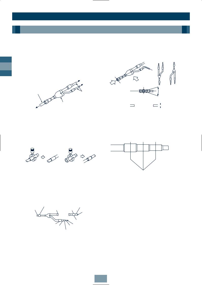
Installation
Piping
Connecting the Branching Kit
Y-shape Branching Joint
Y-shape Branching Joint for gas and liquid
distribution
GB
|
|
To other Branching Pipe |
|
|
or Indoor Unit |
|
Outlet (1) |
|
Piping at site |
|
Piping at site |
|
Inlet |
|
|
Outlet (2) |
|
|
|
|
|
|
Y-shape branching joint for |
|
|
gas side/liquid distribution |
To Outdoor Unit |
|
|
When the selected pipe size differs from the size of the y-shape branching joint pipe, cut the centre of the connecting section with a pipe cutter, as shown below.
•Use the attached auxiliary pipe to adjust the pipe dia. of the Y-shape branching joint at gas or liquid side (RBM-Y071, RBM-Y129). Cut the branched pipe and auxiliary pipe to the specified size, and then braze.
Ø41.3 |
Ø41.3 |
Ø22.2 |
Ø34.9 |
Ø34.9 |
Ø19.0
Auxiliary pipe at gas side
Ø34.9 |
Ø12.7 |
Ø22.2 |
Ø15.9 |
|
Ø19.0 |
Y-shape Joint for gas and liquid distribution
•Install Y-shape branching joint so that it branches horizontally or vertically.
or
B
A
(Horizontal line) |
Within ± 30° |
(A view)
(Horizontal line) 
 Within ± 30° (B view)
•Be sure to fit the insulation to the Y-shape branching joint supplied in the kit.
•Cutting position
Cut at the centre
Cut the pipe at the centre of each connecting section, and remove burr.
Note: All dimensions in (mm)
26

Installation
Piping
Heat Insulating the Branching Pipes
Ensure the pipe insulation covers the piping up to the brazed accessory joints, as this will eliminate ingress of water – tape the pipe insulation to a thickness of 10mm or more, as shown.
RBM-Y129 |
(Gas side) (Prepared at site) |
RBM-Y071 |
(Gas side, Liquid side), |
RBM-Y129 |
(Liquid side) |
Seal the joint with |
Heat insulating |
|
urethane foaming |
||
pipe for piping |
||
agent, etc. |
||
|
||
|
Seal with |
|
Pipe heat |
vinyl tape |
|
|
||
insulator |
Cut by |
|
|
||
|
approx. |
|
|
60° |
Heat insulating |
|
Cut by |
Bring them face |
approx. 90° |
|
pipe for piping |
|
|
to face |
|
|
|
|
Use insulator with a heat resistance of 120° C or over for gas pipes. To insulate the Branching Pipes, use a T-Shaped Joint cover with a thickness of 10mm or over – or a machined insulation portion, as shown.
Place them edge to edge Place them edge to edge
Pipe heat insulator |
Heat insulator |
Pipe heat |
prepared at site |
included accessory |
insulator |
|
|
prepared at site |
150 |
|
|
Branching Pipe |
|
|
|
|
Place them |
Heat insulator (prepared at site), |
edge to edge |
|
10mm or over |
|
|
• After the heat insulating, tape to seal.
Taping |
|
(prepared |
|
at site) |
Heat insulator |
|
(prepared |
Heat insulator |
at site) |
(prepared at site) |
|
Branching Header
Gas side
Prepared at site
Prepared at site
|
To Indoor Unit |
To Outdoor |
|
Unit |
Gas branching header |
Liquid side
Prepared at site
Prepared at site
To Outdoor |
To Indoor Unit |
|
Liquid branching header |
||
Unit |
When the selected pipe size prepared at site differs from the size of the branching header pipe, cut the centre of the connecting section with a pipe cutter
as shown.
If the number of Indoor Units to be connected is less than the number of connections on the Branching Header, braze a pipe cap to the unused connectors.
Gas side
Inlet
Pipe cap
B
Liquid side
B |
Inlet |
Pipe cap |
|
||
|
|
GB
27

Installation
Piping
•Install the branching header so that it branches horizontally. DO NOT install vertically.
Gas side
(Horizontal line)
GB
(B view) Gas side
Liquid side
(Horizontal line)
(B view) Liquid side
•Be sure to insulate the branching header with the insulation provided.
•When routing the branching header at the liquid side from the opposite side, cut both ends and use a pipe cap (not supplied), as shown.
|
A |
B |
C |
To B |
Cut |
Cut |
Cut |
• Support of branching header
Set a hanging metal support (prepared at site) for the branching header, after fitting heat insulation.
• Cutting position
Cut the centre of each connecting section, and remove burr.
To C
Pipe cap
Notes:
Cut at the centre
Use a mini-cutter to cut branching headers up to Ø22.2.
1.Make sure there’s a straight run of pipe at least 300mm long at the inlet side of Y-shaped Branching Joints and Branching Headers.
2.Install Y-shaped Branching Joint so they branch horizontally or vertically. In horizontal installations, set within ± 30°.
3.Install Branching Headers so they branch horizontally.
4.Do not use T-shaped Branching Joints for Branching Sections.
5.When using Y-Branches or Header Branches to prevent incorrect piping, attach a line number or name to each pipe.
Note: All dimensions in (mm)
28
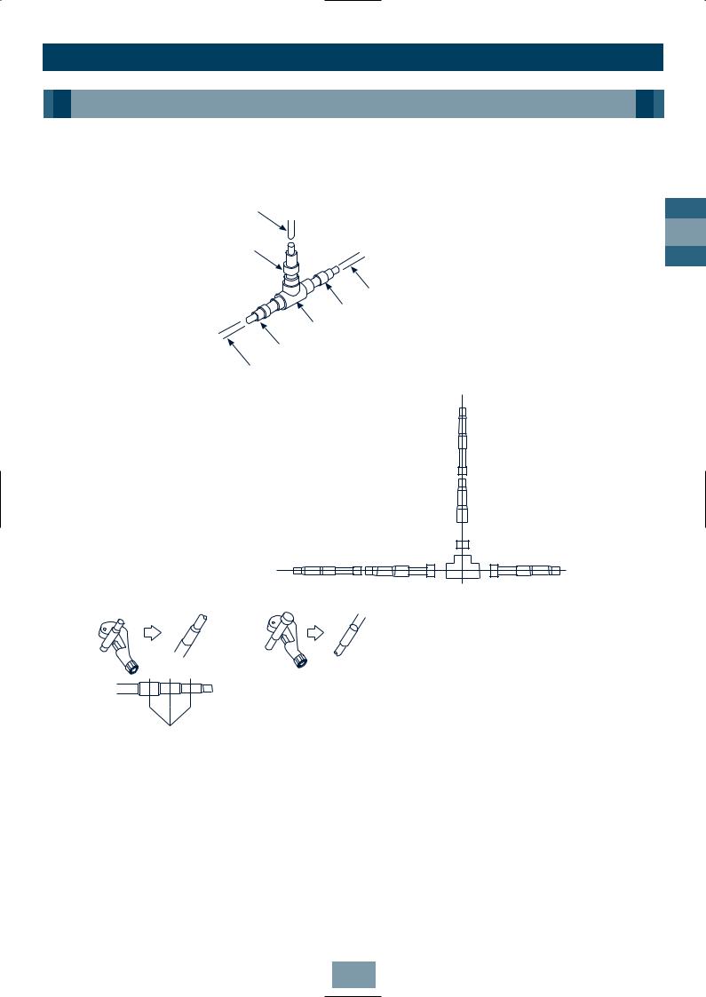
Installation
Piping
T-shape Branching Joint – to Connect Outdoor Units
Branching Pipes at Gas Side/Liquid Side
Pipe prepared at site |
To Outdoor Unit |
|
Connecting pipe at |
To other Branching |
|
gas/liquid side |
||
Pipe or Outdoor Unit |
||
|
||
|
Pipe arranged at site |
|
|
Connecting pipe at gas/liquid side |
|
To other Branching |
Branching Pipe at gas/liquid side |
|
Pipe or Branching |
||
|
||
Section of main pipe |
Connecting pipe at gas/liquid side |
|
|
||
Pipe arranged at site |
||
|
To Outdoor Unit |
|
•Use the included connecting pipes for gas/liquid sides to match to the appropriate pipe size. (The diagram shows a connecting example.)
GB
To other Branching |
|
|
|
To other |
Pipe or Branching |
|
|
|
Branching Pipe |
|
|
|||
Section of main pipe |
|
|
|
or Outdoor Unit |
• Cutting position of connecting pipe
When the selected pipe size prepared at site differs from the size of the Branching Pipe, cut the centre of the connecting section with a pipe cutter.
Cut the centre
29

|
|
|
Installation |
|
|
|
|
Piping |
|
|
Installation of Gas/Liquid Branching Pipes |
|
||
|
Inverter |
Fixed-speed |
Inverter |
Fixed-speed |
|
Outdoor Unit |
Outdoor Unit |
Outdoor Unit |
Outdoor Unit |
GB |
|
|
||
|
|
|
|
|
INCORRECT |
ROUTING |
Balancing Branch Pipes (Oil)
To Outdoor |
Pipe prepared |
|
Unit |
||
at site |
||
|
||
|
To other |
|
|
Branching Pipe |
|
|
or Outdoor Unit |
When combining two units, connect directly.
Inverter Fixed-speed
Outdoor Unit Outdoor Unit
To other |
Pipe prepared |
|
|
at site |
Connect |
||
Branching Pipe |
Branching Pipe for |
Balancing |
|
or Outdoor Unit |
Pipe directly |
||
Balancing Pipe (included) |
|||
|
|
||
|
Pipe prepared at site |
|
Heat Insulation
Insulate liquid side, gas side and Balancing Pipes separately. Use insulator with a resistance of 120°C + for gas pipes.
To insulate the Branching Pipes, use a T-Shaped Joint cover with a thickness of 10mm or over
– or the machined one included. (Insulation for branching is not included.)
To prevent condensation or dripping – seal the Branching Pipe securely, with no gaps.
Heat insulating pipe for piping
Seal the joint with urethane foaming agent, etc.
Seal with vinyl tape
Heat insulating pipe for piping
Heat insulator
 External dia. of
Branching Pipe
Drill a hole with dia. larger than external dia. of heat insulating pipe for piping
30
 Loading...