


INSTRUCTION MANUAL
3 CCD CAMERA
IK-TF5C
For Customer Use
Enter below the Serial No. w h i c h i s l o c a t e d o n t h e bottom of the cabinet. Retain this information for future reference.
Model No.: IK-TF5C
Serial No.:
FCC NOTICE
This equipment has been tested and found to comply with the limits for a Class A digital device, pursuant to Part 15 of the FCC Rules. These limits are designed to provide reasonable protection against harmful interference when the equipment is operated in a commercial environment. This equipment generates, uses, and can radiate radio frequency energy and, if not installed and used in accordance with the instruction manual, may cause harmful interference to radio communications. Operation of this equipment in a residential area is likely to cause harmful interference in which case the user will be required to correct the interference at his own expense.
USER-INSTALLER CAUTION: Your authority to operate this FCC verified equipment could be voided if you make changes or modifications not expressly approved by the party responsible for compliance to Part 15 of the FCC Rules.
This Class A digital apparatus complies with Canadian ICES-003.
Cet appareil numérique de la classe A est comforme à la norme NMB-003 du Canada.
Following information is only for EU-member states:
The use of the symbol indicates that this product may not be treated as household waste.
By ensuring this product is disposed of correctly, you will help prevent potential negative consequences for the environment and human health, which could otherwise be caused by inappropriate waste handling of this product. For more detailed information about the takeback and recycling of this product, please contact your supplier where you purchased the product or consult.
SAFETY PRECAUTIONS
Safety icons
This manual contains safety instructions that must be observed in order to avoid potential hazards that could result in personal injuries, damage to your equipment, or loss of data. These safety cautions have been classified according to the seriousness of the risk, and the icons highlight these instructions as follows:
Indicates a potentially hazardous situation which, if not avoided, could result in death or serious injury.
Indicates a potentially hazardous situation which, if not avoided, may result in minor or moderate injury.
Indicates a potentially hazardous situation which, if not avoided, may result in property damage.
Stop operation immediately when any abnormality or defect occurs.
Use during an abnormal condition; such as emitting smoke, burning odors, damage from dropping invasion of foreign objects, etc. may cause fire and/or electric shock. Immediately stop the power source and contact your dealer.
Avoid installing in a shower room or a bathroom.
This may cause fire and/or electric shock.
Do not operate in places with possibility of becoming wet.
This may cause fire and/or electric shock.
Do not repair, disassemble and/or modify by yourself.
This may cause fire and/or electric shock. Be always sure to contact your dealer for internal repair, check and cleaning of the product.
Use the specified power supply.
Otherwise, a fire or an electric shock may occur.
Don’t place things or materials on the unit.
Ingress of foreign materials such as metallic things and liquid into the product may cause a fire or an electric shock.
Do not put the product in an unstable, slanting and/or vibrated place.
Drop and/or fall of the product may cause serious injury.
Do not touch the product and/or any connection cables during a thunderstorm.
This might cause electric shock.
2
Note the following instructions when installing.
•Do not cover the product by any material.
•Do not put the product on an Inflammable material such as carpet or blanket.
•Do not put the product in a narrow space, since the heat generated from the
product may be difficult to emanate.
If you do not follow the above, the heat generated by the product may cause fire.
Do not put the product in direct sunshine and/or high temperature.
The temperature inside the product may cause fire.
Avoid setting in humid, smoky, vaporized or dusty places.
This may cause fire and/or electric shock.
Do not point the lens directly at the sun and/or intensive light such as direct sunlight, etc.
Focusing of the light may cause injury of eye and/or fire.
Ask your dealer to perform a periodical check and internal cleaning (approx. once every five years).
Dust inside the product may cause fire and/or trouble. For check and cleaning cost, please consult your dealer.
Disclaimer
We disclaim any responsibility and shall be held harmless for any damages or losses incurred by the user in any of the following cases:
1.Fire, earthquake or any other act of God; acts by third parties; misuse by the user, whether intentional or accidental; use under extreme operating conditions.
2.Malfunction or non-function resulting in indirect, additional or consequential damages, including but not limited to loss of expected income and suspension of business activities.
3.Incorrect use not in compliance with instructions in this instruction manual.
4.Malfunctions resulting from misconnection to other equipment.
5.Repairs or modifications made by the user or caused to be made by the user and carried out by an unauthorized third party.
6.Notwithstanding the foregoing, Toshiba’s liabilities shall not, in any circumstances, exceed the purchase price of the product.
Copyright and Right of Portrait
There may be a conflict with the Copyright Law and other laws when a customer uses, displays, distributes, or exhibits an image picked up by the camera without permission from the copyright holder. Please also note that transfer of an image or file covered by copyright is restricted to use within the scope permitted by the Copyright Law.
3

TABLE OF CONTENTS
1. CAUTIONS ON USE AND INSTALLATION ..... |
5 |
7. 3 External Sync ............................................ |
22 |
|||||
2. COMPONENTS ................................................ |
5 |
( 1 ) External sync signal input conditions ...... |
22 |
|||||
3. ITEMS CONTROLLED BY USING |
|
( 2 ) External sync frequency range ............... |
22 |
|||||
|
( 3 ) Using the unit with external sync signal |
23 |
||||||
ON SCREEN DISPLAY |
6 |
|||||||
(3. 1) H (horizontal) phase adjustment |
23 |
|||||||
|
|
|
|
|
|
|||
4. NAMES AND FUNCTIONS .............................. |
7 |
( 4 ) Changing HD/VD input/output ................ |
23 |
|||||
5. CONNECTION |
8 |
7. 4 Synchro. Scan Operation ......................... |
23 |
|||||
|
|
|||||||
5. 1 |
Standard Connection |
8 |
( 1 ) Setting by 1H .......................................... |
23 |
||||
( 2 ) Setting by the frame |
23 |
|||||||
5. 2 |
Cautions on Connection |
8 |
||||||
7. 5 EXT TRIG (External trigger) |
24 |
|||||||
5. 3 |
Connector Pin Assignments ..................... |
8 |
||||||
6. OPERATION |
..................................................... |
9 |
( 1 ) 1P SNR (1 Pulse Sync Non Reset) ........ |
24 |
||||
6. 1 |
White Balance |
9 |
(1. 1) 1 Pulse Trigger SYNC-NON RESET |
|
||||
Picture Output Timing |
24 |
|||||||
6. 2 |
Gain |
|
|
10 |
||||
........................................................ |
|
(1. 2) 1 Pulse Trigger SYNC-NON RESET |
|
|||||
6. 3 |
Shading .................................Correction |
10 |
Picture Output Timing (at Time of |
|
||||
7. MODE SETTING .....BY ON SCREEN DISPLAY |
11 |
Internal Sync) ................................... |
25 |
|||||
7. 1 |
Using the Menus |
11 |
( 2 ) 1P SR (1 Pulse Sync Reset) ................... |
26 |
||||
(2. 1) 1 Pulse Trigger SYNC-RESET Picture |
||||||||
7. 2 |
Menus |
|
12 |
|||||
|
Output Timing ................................... |
26 |
||||||
( 1 ) SHUTTER ................(Electronic shutter) |
12 |
( 3 ) PW SNR (Pulse width trigger |
|
|||||
|
(1. |
1) Changing each setting in |
|
SYNC-NON RESET) .............................. |
27 |
|||
|
|
..................................... |
MANU mode |
12 |
(3. 1) Pulse Width Trigger SYNC-NON RESET |
|||
|
(1. |
2) |
Changing each setting in |
|
Picture Output Timing ...................... |
27 |
||
|
|
................. |
SS (synchro. scan) mode |
13 |
(3. 2) Pulse Width Trigger SYNC-NON RESET |
|||
|
(1. |
3) |
Changing each setting in |
|
Picture Output Timing (at Time of |
|
||
|
|
..................................... |
E.TRG mode |
14 |
Internal Sync) ................................... |
28 |
||
|
(1. |
3. 1) |
Changing each setting in |
|
( 4 ) PW SR (Pulse width trigger |
|
||
|
|
|
|
1P SNR mode |
14 |
|
||
|
|
............................... |
|
SYNC-RESET) |
29 |
|||
|
(1. |
3. 2) |
Changing each setting in |
|
||||
|
|
(4. 1) 1 Pulse Width Trigger SYNC-RESET |
|
|||||
|
|
................................. |
|
1P SR mode |
15 |
Picture Output Timing |
29 |
|
|
(1. |
3. 3) |
Changing each setting in |
|
||||
|
|
( 5 ) RR (Reset restart) |
30 |
|||||
|
|
|
|
PW SNR mode |
16 |
|||
|
|
............................. |
|
(5. 1) Long Term Exposure |
30 |
|||
|
(1. |
3. 4) |
Changing each setting in |
|
||||
|
|
(5. 2) Input Timing Chart Example |
30 |
|||||
|
|
|
|
PW SR mode |
17 |
|||
|
|
................................ |
|
7. 6 Partial Read |
31 |
|||
|
(1. |
3. 5) |
Changing each setting in |
|
||||
|
|
....................................... |
|
RR mode |
18 |
( 1 ) Partial Scanning OFF |
|
|
( 2 ) GAIN (Video gain) |
18 |
|
||||||
(All pixels scanning) ................................ |
31 |
|||||||
|
(2. |
1) ........ |
Changing each setting in GAIN |
18 |
( 2 ) Partial Scanning ON |
31 |
||
( 3 ) WHT BAL (White balance) |
19 |
|||||||
( 3 ) When Partial Scanning Mode is ON |
31 |
|||||||
|
(3. |
1) |
Changing each setting in AWB |
|
||||
|
|
8. INPUT OUTPUT SIGNAL SPECIFICATOINS |
32 |
|||||
|
|
.... |
(Automatic White Balance) mode |
19 |
||||
|
(3. |
2) |
Changing each setting in MANU |
19 |
( 1 ) HD/VD Output Amplitude Specifications ... |
32 |
||
|
|
................................. |
(Manual) mode |
( 2 ) VD Input Specifications |
32 |
|||
( 4 ) PROCESS |
20 |
|||||||
( 3 ) VIDEO INDEX Output Specifications |
32 |
|||||||
|
(4. |
1) |
Changing master pedestal |
20 |
||||
|
( 4 ) HD Input Specifications |
32 |
||||||
|
(4. |
2) |
Changing R pedestal |
20 |
||||
|
( 5 ) Trigger Pulse Specifications |
32 |
||||||
|
(4. |
3) ........................ |
Changing B pedestal |
20 |
||||
|
(4. |
4) ...Changing the shading correction mode |
20 |
( 6 ) External HD/VD Input Phase |
|
|||
|
(4. 5) ...Changing the manual shading correction seting |
20 |
Specifications .......................................... |
32 |
||||
( 5 ) SYNC ...................................................... |
|
21 |
9. CCD OUTPUT WAVEFORM TIMING CHART ... |
33 |
||||
|
(5. |
1) ............... |
Adjusting horizontal phase |
21 |
( 1 ) Horizontal Output Waveform Timing Chart |
33 |
||
( 6 ) OPTION |
21 |
|||||||
( 2 ) Vertical Output Waveform Timing Chart |
33 |
|||||||
|
(6. |
1) |
Changing serial communication baud |
|||||
|
10. SPECIFICATIONS |
34 |
||||||
|
|
.................................................... |
rate |
21 |
||||
( 7 ) |
Setting ...............to factory setting status |
22 |
11. EXTERNAL APPEARANCE DIAGRAM |
35 |
||||
|
|
|
|
|
|
|||
|
|
|
|
|
|
12. BEFORE MAKING A SERVICE CALL ........ |
35 |
|
4

1. CAUTIONS ON USE AND INSTALLATION
• Carefully handle the units. |
• Handling of the protection cap. |
|
Do not drop, or give a strong shock or vibration to |
Keep the protection cap away from children. Chil- |
|
the camera. This may cause problems. Treat the |
dren may put them into mouth or swallow them |
|
camera cables carefully to prevent cable prob- |
accidentally. The protection cap protects the im- |
|
lems, such as cable breakdown and loosened con- |
age sensing plane when the lens is removed from |
|
nections. |
the camera, do not throw away. |
|
• Do not shoot intense light. |
• When not using the camera for a longtime. |
|
If there is an intense light at a location on the |
Stop supplying power. |
|
screen such as a spot light, a blooming and smear- |
• When cleaning the camera. |
|
ing may occur. When intense light enters, vertical |
||
Unplug the power source before cleaning. Clean |
||
stripes may appear on the screen. This is not a |
||
with a soft dry cloth only. Do not use benzine, al- |
||
malfunction. Ghosts may occur when there is an |
||
cohol, thinner, household detergents, chemically |
||
intense light near the object. In this case, change |
||
treated cloths, etc. If used, coating and printed |
||
the shooting angle. |
||
letters may be discolored. When cleaning the lens, |
||
• Install the camera in a location free from noise. |
||
use a lens cleaning paper, etc. |
||
If the camera or the cables are located near power |
• Avoid using or storing the camera in the fol- |
|
utility lines or a TV, etc. undesirable noise may |
||
lowing places: |
||
appear on the screen. In such a case, try to change |
||
Places filled with highly flammable gas. |
||
the location of the camera or the cable wiring. |
||
|
||
• Moire |
Places near gasoline, benzene, or paint thinner. |
|
Places subject to strong vibration. |
||
When thin stripe patterns are shot, stripe patterns |
||
|
||
that are not actually there (moire) may appears |
Places contacting chemicals (such as pesticides), |
|
as interference stripes. This is not a malfunction. |
rubber or vinyl products for a long period of time. |
|
• Operating ambient temperature and humidity. |
• Preliminary confirmation of the location where |
|
Do not use the camera in places where tempera- |
the camera is installed (with a tripod not used) |
|
|
||
ture and humidity exceed the specifications. Pic- |
Before installing the camera, make sure that the |
|
ture quality will lower and internal parts may be |
||
damaged. |
||
|
location can withstand the total weight of the |
|
|
camera. |
|
Be particularly careful when using in places ex- |
If the camera is installed in places where the |
|
posed to direct sunlight. When shooting in hot |
strength of bearing it is insufficient, secure the |
|
places, depending on the conditions of the object |
structure by reinforcement etc., to bear the load. |
|
and the camera (for example when the gain is in- |
If the reinforcement strength is insufficient, the |
|
creased), noise in the form of vertical strips or |
camera may drop, causing personal injury and |
|
white dots may occur. This is not a malfunction. |
malfunction. |
2. COMPONENTS |
|
|
(1) |
Camera ........................................................................................................................................... |
1 |
(2) |
Accessories |
|
|
(a) Instruction manual ................................................................................................................... |
1 |
5

3. ITEMS CONTROLLED BY USING ON SCREEN DISPLAY
Item |
Available selections |
Preset value |
|
(Factory setting) |
|||
|
|
|
MODE |
|
MANU, SS, E. TRG |
MANU |
|
|
E. TRG |
|
1P SNR, 1P SR, PW SNR, PW SR, RR |
1P SNR |
|
|
MANU speed |
OFF, 1/100s, 1/250s, 1/500s, 1/1000s, 1/2000s, |
OFF |
||
Electronic |
|
|
1/4000s, 1/10000s, 1/25000s, 1/50000s, 1/1000000s |
|
|
Syncro. Partial read OFF |
1H/525H~524H/525H, OFF, 2FRM~512FRM |
OFF |
|||
scan. |
Partial read 120fps |
1H/262H~261H/262H, OFF, 2FRM~512FRM |
|
||
|
Partial read 180fps |
1H/175H~174H/175H, OFF, 2FRM~512FRM |
|
||
Partial read |
OFF, 120fps, 180 fps, E.120fps, E.180fps |
OFF |
|||
shutter |
|||||
Trigger |
|
, |
|
||
(1P SNR/SR) |
|
||||
|
|
||||
|
Trigger |
|
, |
|
|
|
(PW SNR/SR) |
|
|||
|
|
|
|||
|
1P |
|
0.01ms~16ms |
16 ms |
|
|
exposure time |
|
|||
|
|
|
|||
Gain |
MODE |
|
MANU, OFF |
OFF |
|
MANU |
|
-3dB~18dB |
0dB |
||
|
|
||||
balance White |
MODE |
|
AWB, MANU |
AWB |
|
Color temperature |
3200K, 5600K |
3200K |
|||
MANUAL R GAIN |
-100~0~100 |
0 |
|||
MANUAL B GAIN |
-100~0~100 |
0 |
|||
|
|||||
|
Master pedestal |
-64~0~64 |
0 |
||
Process |
R pedestal |
-64~0~64 |
0 |
||
B pedestal |
-64~0~64 |
0 |
|||
Shading correction |
MANU, OFF |
MANU |
|||
mode |
|
|
|
||
|
Manual shading |
-128~0~127 |
0 |
||
|
correction |
|
|
||
Sync |
H phase adjustment |
-100~0~100 |
0 |
||
|
|
|
|
||
Option |
Baud rate |
9600 bps, 19200 bps |
9600 bps |
||
|
|
|
|
||
6
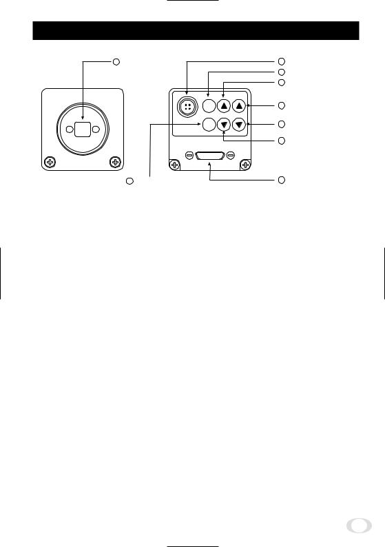
4. NAMES AND FUNCTIONS
1 |
Prism faceplate |
8 |
DC IN 12V terminal |
|
|
2 |
DISP button |
|
|
4 |
MENU UP button |
|
(AWB) |
|
|
|
DISP |
6 |
DATA UP (AWB) button |
|
MENU DATA |
|
|
|
DC IN 12V |
7 |
DATA DOWN button |
|
PAGE |
||
|
|
5 |
MENU DOWN button |
|
3 PAGE button |
9 |
DIGITAL terminal |
[ Front ] |
[ Rear ] |
|
|
1 Prism faceplate |
The protection cap is attached on the lens mount portion. After removing the cap, |
||
|
mount the lens. Be careful not to scratch or touch the optical area. |
||
2 DISP button |
Used when switching the display. |
|
|
3 PAGE button |
Used when switching to the menu and when selecting the menus. |
||
4 MENU UP button |
Select the function to be confirmed or changed on the menu. |
||
5 MENU DOWN button |
Select the function to be confirmed or changed on the menu. |
||
6 DATA UP (AWB) button |
Changes the value of the function selected by the MENU (UP/DOWN) button. (Also |
||
|
used when using AWB.) |
|
|
7 DATA DOWN button |
Changes the value of the function selected by the MENU (UP/DOWN) button. |
||
8 DC IN 12V terminal |
Accept a DC power input (12V). |
|
|
9 RGB terminal |
8-bit RGB, digital signal, and sync signal are output in the Camera Link format. |
||
Trigger signal and external sync signal (HD,VD) are input.
Mode switching signal for partial scanning is input.
Accepts serial communication control signal.
7
5. CONNECTION
5. 1 Standard Connection
Lens |
Cable (not included) |
|
|
|
|
|
|||||||
|
|
|
|
|
|||||||||
|
|
|
|
|
|
IK-TF5C |
|
|
|
|
|
||
|
|
|
|
|
|
|
|
|
|||||
|
|
|
|
|
|
DC IN 12V |
|
|
|
|
|
|
|
|
|
|
|
|
|
|
|
|
|
|
|
|
|
|
|
|
|
|
|
|
Frame grabber board, |
|
Monitor |
||||
|
|
|
|
Less than 4 mm |
|
|
|||||||
|
|
|
|
DC power |
image process |
|
|
|
|||||
|
|
|
|
|
|
|
|
|
|
||||
|
|
|
|
|
|
|
equipment etc. |
|
|
|
|||
|
|
|
|
|
|
|
supply |
|
|
|
|||
|
|
|
|
|
|
|
|
|
|
|
|
|
|
5. 2 Cautions on Connection
•When connecting the camera cables, unplug the power source of the camera and the other equipment connected.
•We suggest using a C mount lens made for a 3CCD camera.
When using another lens, the best camera performance of this camera may not be obtained.
(For example, low resolution may occur, focus may be lost through the range of a zoom lens, and flare, ghost or shading may occur)
Furthermore, in order to avoid damaging the mounting portion of the camera head, use a lens which has projection dimension from the mounting base of less than 0.157"(4mm).
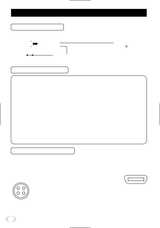
•For DC power supply connecting to DC IN 12V terminal, use UL listed and/or CSA approved ungrounding type AC adaptor with the specifications described below.
Power supply voltage |
: DC12V±10% |
|
Current rating |
: More than 830 mA |
|
Ripple voltage |
: Less than 50 mV(p–p) |
|
Connector |
: HR10A–7P–4S by HIROSE electronics Co. Ltd |
|
|
Pins 1, 2 |
: 12V |
|
Pins 3, 4 |
: GND |
5. 3 Connector Pin Assignments
DC IN 12V |
DIGITAL |
|
|
Function |
I/O |
|||||
1 |
|
+12V |
|
1 |
GND |
14 |
GND |
|
– |
|
2 |
|
+12V |
|
2 |
X0- |
15 |
X0+ |
|
O |
|
3 |
|
GND |
|
3 |
X1- |
16 |
X1+ |
|
O |
|
4 |
|
GND |
|
4 |
X2- |
17 |
X2+ |
|
O |
|
|
|
|
|
5 |
Xcllk- |
18 |
Xcllk+ |
|
O |
|
|
|
|
|
6 |
X3- |
19 |
X3+ |
|
O |
|
|
|
|
|
|
|
|
|
|
|
|
1 |
3 |
|
7 |
SerTC+ |
20 |
SerTC- |
Serial communication control (RXD) |
I |
||
|
8 |
SerTFC- |
21 |
SerTFC+ |
Serial communication control (TXD) |
O |
||||
|
|
|
|
|||||||
2 |
4 |
|
9 |
CC1- |
22 |
CC1+ |
Trigger pulse input |
I |
||
|
|
|
|
10 |
CC2+ |
23 |
CC2- |
Partial scanning control |
I |
|
Connector used: |
11 |
CC3- |
24 |
CC3+ |
External HD input |
I |
||||
12 |
CC4+ |
25 |
CC4- |
External VD input |
I |
|||||
HR10A-7P-4PB |
||||||||||
(HIROSE electronics |
13 |
GND |
26 |
GND |
|
– |
||||
Co. Ltd) or equivalent.
13 |
1 |
26 |
14 |
Connector used:
12226-51000-00
(3M) or equivalent.
8

6. OPERATION
1 Refer to the item " 5. CONNECTION", connect each equipment correctly.
2 Turn on the connected equipment and the power source of the camera.
3 Point the lens at the object, operate the lens iris adjustment, focus adjustment, etc..
4 Refer to the item "6.1 White Balance", operate the adjustment.
5 Refer to the items "6.2 Gain, 7. MODE SETTING BY ON SCREEN DISPLAY", select the necessary items.
6. 1 White Balance
For the white balance adjustment for this unit, AWB (Automatic White Balance) and MANU (Manual white balance) adjustments are provided. To select the desired mode, refer to the items “7.2 (3) WHT BAL (White balance)” and “7. MODE SETTING BY ON SCREEN DISPLAY”.
|
AWB |
MANU |
|
(Automatic White Balance) |
(Manual White Balance) |
Outline |
Adjust white balance by displaying the |
Adjust the white balance manually using |
|
white object inside the area set by AWB |
the WHT BAL menu while shooting the |
|
menu and pressing the [DATA UP] button. |
white object. |
Note |
When the shutter mode is E.TRG, AWB is |
Adjustment is performed by confirming |
|
not available. |
with a monitor etc. |
1AWB (Automatic white balance)
•Set the MODE to AWB on the WHT BAL menu.
Perform the C.TEMP (color temperature conversion) setting, if necessary. (Refer to the item "7.2 (3) WHT BAL (White balance)".)
3200K : Appropriate for indoor shooting.
5600K : Appropriate for outdoor shooting.
•If the index menu/menu is displayed, press the [DISP] button to disable the character display on the menu.
•Shoot a known white object that fills the screen and push [DATA UP] button for approx. 1 second.
•The character AWB blinks on the screen when the AWB starts.
•The character AWB stops blinking when the AWB finishes, and the result is displayed for approx. 1 second.
Result displayed |
Meaning |
AWB OK |
Automatic white balance adjustment finished correctly. |
AWB NG LEVEL |
Automatic white balance adjustment cannot be performed because the |
LOW |
video level is too low. |
|
Get the video level propely. |
AWB NG |
Automatic white balance adjustment cannot be performed because the |
LEVEL HIGH |
video level is too high. |
|
Get the video level propely. |
AWB NG |
Automatic white balance adjustment cannot be performed because the |
C. TEMP HIGH |
color temperature is too low. |
|
If the C.TEMP is set to 5600K, set to 3200K. |
|
If the message appears with the C.TEMP set to 3200K, change the |
|
illumination or use a color temperature conversion filter. |
AWB NG |
Automatic white balance adjustment cannot be performed because the |
C. TEMP HIGH |
color temperature is too high. |
|
If the C.TEMP is set to 3200K, set to 5600K. |
|
If the message appears with the C.TEMP set to 5600K, change the |
|
illumination or use the color temperature conversion filter. |
|
|
9

Result displayed |
Meaning |
AWB NG |
Automatic white balance adjustment cannot be performed because the |
NOT AVAILABLE |
shutter speed mode is E.TRG mode. |
AWB NG |
Automatic white balance adjustment cannot be performed for other |
|
reasons. Such as no white area is included in an object, etc. |
2MANU (Manual white balance)
•Set the MODE to MANU on the WHT BAL menu. (Refer to the item "7.2 (3) WHT BAL (white balance)".)
•Shoot a known white object, adjust the white balance adjusting the levels of R GAIN and B GAIN on the menu, confirming with a monitor etc.
(Refer to the item "7.2 (3) (3.2) Changing each setting in MANU mode".)
6. 2 Gain
When the image is dark even if the lens iris is open, change the gain (video gain) to get the proper video level.
For the gain adjustment of the unit, MANU (Manual) and OFF (0 dB) modes are provided. Select the mode on the GAIN menu. (Refer to the item "7.2 (2) GAIN (Video gain)".)
1MANU (Manual gain)
Gain adjustment is performed on the GAIN menu. The adjustment range is from -3dB to 18dB in 1dB steps. (Refer to the item "7.2 (2) (2.1) (a) Changing the gain in MANU mode".)
2OFF
Gain is fixed at 0 dB.
6. 3 Shading Correction
Due to the lens used or the environmental condition, vertical color shading may occur at the top and bottom of the screen. In this case, the shading correction can decrease the color shading. For the shading correction of the unit, MANU (Manual shading correction) and OFF (no shading correction) modes are provided. Select the mode on the PROCESS menu. (Refer to the item "7.2 (4) (4.4) Changing the shading correction mode".)
1MANU (Manual Shading)
Adjust the correction amount on the PROCESS menu by confirming with a monitor or a waveform monitor. (Refer to the "7.2 (4) (4.5) Changing the manual shading correction setting".)
2OFF
The status is no shading correction.
*The shading correction is effective when the lens iris or zoom ratio is fixed. Use the unit with SHAD. OFF for variable lens conditions.
10
7. MODE SETTING BY ON SCREEN DISPLAY
Various settings can be controlled on the unit by using the on screen menu displayed on the monitor. The contents once set are memorized even if the power source is turned off, so it is unnecessary to set again when using the unit next time. When the setting is performed, select the menu of the item to be set.
7. 1 Using the Menus
When the power is turned on, the normal screen showing only the video signal appears. Change the output to each screen (video signal output, Index menu, and menus) by using the [DISP], [PAGE], [MENU UP], and [MENU DOWN] buttons.
*A menu is selected when pushing the [PAGE] button after moving the "→" on the screen by the [MENU UP], [MENU DOWN] button while the Index menu is displayed.
POWER ON
Video signal output |
Index menu |
|
DISP |
|
DISP |
|
DISP |
|
|
|
|
|
|
|
|
|
|
|
|
|
|
||
PAGE |
|
PAGE |
|
|
Menus |
|
|
|
|
|
|
|
|
|
|
|
|
|
|
||
|
|
|
|
WHT BAL |
|
|
|
|
|
PAGE |
SHUTTER |
|
GAIN |
|
|
PROCESS |
|
SYNC |
|
OPTION |
|
MANU |
PAGE |
MANU |
PAGE |
AWB |
PAGE |
SHAD. |
PAGE |
INT |
PAGE |
BAUD |
|
|
|
|
|
|
MANU |
|
|
|
RATE |
SS |
|
OFF |
|
MANU |
|
SHAD. |
|
EXT |
|
|
|
|
|
|
|
|
OFF |
|
|
|
|
E. TRG |
|
|
|
|
|
|
|
|
|
|
1P SR |
|
|
|
|
|
|
|
|
|
|
E. TRG |
|
|
|
|
|
|
|
|
|
|
1P SNR |
|
|
|
|
|
|
|
|
|
|
E. TRG |
|
|
|
|
|
|
|
|
|
|
PW SR |
|
|
|
|
|
|
|
|
|
|
E. TRG |
|
|
|
|
|
|
|
|
|
|
PW SNR |
|
|
|
|
|
|
|
|
|
|
E. TRG |
|
|
|
|
|
|
|
|
|
|
RR |
|
|
|
|
|
|
|
|
|
|
11
 Loading...