


Toshiba HWS-1403XWHD6-E, HWS-803XWHD6-E, HWS-1403XWHT9-E, HWS-1403H-E, HWS-1603H8R-E DATA BOOK
...A10-006
AIR TO WATER HEAT PUMP
SERVICE MANUAL
Model name:
Hydro Unit
HWS-803XWHM3-E(TR) HWS-803XWHT6-E(TR) HWS-803XWHD6-E HWS-803XWHT9-E HWS-1403XWHM3-E(TR) HWS-1403XWHT6-E(TR) HWS-1403XWHD6-E HWS-1403XWHT9-E(TR)
Outdoor Unit
HWS-803H-E(TR) HWS-1103H-E(TR) HWS-1403H-E(TR) HWS-1103H8-E HWS-1103H8R-E HWS-1403H8-E HWS-1403H8R-E HWS-1603H8-E HWS-1603H8R-E
Hot Water Cylinder
HWS-1501CSHM3-E(-UK) HWS-2101CSHM3-E(-UK) HWS-3001CSHM3-E(-UK)

Contents
1 SAFETY PRECAUTIONS . . . . . . . . . . . . . . . . . . . . . . . . . . . . . . . . . . . . . . . . . . . . . . . . 3
2 NEW REFRIGERANT (R410A). . . . . . . . . . . . . . . . . . . . . . . . . . . . . . . . . . . . . . . . . . . . 6
2-1.Safety During Installation and Service . . . . . . . . . . . . . . . . . . . . . . . . . . . . . . . . . . . . . . . . . . . . . . . 6 2-2.Installing refrigerant pipe . . . . . . . . . . . . . . . . . . . . . . . . . . . . . . . . . . . . . . . . . . . . . . . . . . . . . . . . . 7 2-2-1.Steel pipe and joint . . . . . . . . . . . . . . . . . . . . . . . . . . . . . . . . . . . . . . . . . . . . . . . . . . . . . . . 7 2-2-2.Processing of piping materials . . . . . . . . . . . . . . . . . . . . . . . . . . . . . . . . . . . . . . . . . . . . . . 8 2-3.Tools. . . . . . . . . . . . . . . . . . . . . . . . . . . . . . . . . . . . . . . . . . . . . . . . . . . . . . . . . . . . . . . . . . . . . . . . 10 2-3-1.Necessary tools. . . . . . . . . . . . . . . . . . . . . . . . . . . . . . . . . . . . . . . . . . . . . . . . . . . . . . . . . 10 2-4.Recharging of refrigerant . . . . . . . . . . . . . . . . . . . . . . . . . . . . . . . . . . . . . . . . . . . . . . . . . . . . . . . . 11 2-5.Brazing of pipes . . . . . . . . . . . . . . . . . . . . . . . . . . . . . . . . . . . . . . . . . . . . . . . . . . . . . . . . . . . . . . . 13 2-5-1.Materials of brazing. . . . . . . . . . . . . . . . . . . . . . . . . . . . . . . . . . . . . . . . . . . . . . . . . . . . . . 13 2-5-2.Flux . . . . . . . . . . . . . . . . . . . . . . . . . . . . . . . . . . . . . . . . . . . . . . . . . . . . . . . . . . . . . . . . . . 13 2-5-3.Brazing . . . . . . . . . . . . . . . . . . . . . . . . . . . . . . . . . . . . . . . . . . . . . . . . . . . . . . . . . . . . . . . 13
3 Specifications . . . . . . . . . . . . . . . . . . . . . . . . . . . . . . . . . . . . . . . . . . . . . . . . . . . . . . . 15
4 Outside Drawing . . . . . . . . . . . . . . . . . . . . . . . . . . . . . . . . . . . . . . . . . . . . . . . . . . . . . 18
4-1.Hydro unit . . . . . . . . . . . . . . . . . . . . . . . . . . . . . . . . . . . . . . . . . . . . . . . . . . . . . . . . . . . . . . . . . . . . 18 4-2.Outdoor unit . . . . . . . . . . . . . . . . . . . . . . . . . . . . . . . . . . . . . . . . . . . . . . . . . . . . . . . . . . . . . . . . . . 19 4-3.Hot water cylinder. . . . . . . . . . . . . . . . . . . . . . . . . . . . . . . . . . . . . . . . . . . . . . . . . . . . . . . . . . . . . . 21
5 Wiring Diagram . . . . . . . . . . . . . . . . . . . . . . . . . . . . . . . . . . . . . . . . . . . . . . . . . . . . . . 22
5-1.Hydro Unit. . . . . . . . . . . . . . . . . . . . . . . . . . . . . . . . . . . . . . . . . . . . . . . . . . . . . . . . . . . . . . . . . . . . 22 5-2.Outdoor Unit (Single phase Type) . . . . . . . . . . . . . . . . . . . . . . . . . . . . . . . . . . . . . . . . . . . . . . . . . 23 5-3.Outdoor Unit (3 phase type) . . . . . . . . . . . . . . . . . . . . . . . . . . . . . . . . . . . . . . . . . . . . . . . . . . . . . . 24 5-4.Hot Water Cylinder Unit . . . . . . . . . . . . . . . . . . . . . . . . . . . . . . . . . . . . . . . . . . . . . . . . . . . . . . . . . 25
6 Key Electric Component Rating. . . . . . . . . . . . . . . . . . . . . . . . . . . . . . . . . . . . . . . . . 26
6-1.Hydro Unit. . . . . . . . . . . . . . . . . . . . . . . . . . . . . . . . . . . . . . . . . . . . . . . . . . . . . . . . . . . . . . . . . . . . 26 6-2.Outdoor Unit . . . . . . . . . . . . . . . . . . . . . . . . . . . . . . . . . . . . . . . . . . . . . . . . . . . . . . . . . . . . . . . . . . 28 6-3.Hot Water Cylinder Unit . . . . . . . . . . . . . . . . . . . . . . . . . . . . . . . . . . . . . . . . . . . . . . . . . . . . . . . . . 31 6-4.Water Heat Exchange Control Board . . . . . . . . . . . . . . . . . . . . . . . . . . . . . . . . . . . . . . . . . . . . . . . 32 6-5.Outdoor Control Board (Single phase Type) . . . . . . . . . . . . . . . . . . . . . . . . . . . . . . . . . . . . . . . . . 33 6-6.Outdoor Unit Control (3 phase type). . . . . . . . . . . . . . . . . . . . . . . . . . . . . . . . . . . . . . . . . . . . . . . . 35
MCC-1596 (Compressor IPDU) . . . . . . . . . . . . . . . . . . . . . . . . . . . . . . . . . . . . . . . . . . . . . . . . . 35 MCC-1597 (Fan Motor IPDU). . . . . . . . . . . . . . . . . . . . . . . . . . . . . . . . . . . . . . . . . . . . . . . . . . . 36 MCC-1599 (Interface (CDB)) . . . . . . . . . . . . . . . . . . . . . . . . . . . . . . . . . . . . . . . . . . . . . . . . . . . 37 MCC-1600 (Noise Filter). . . . . . . . . . . . . . . . . . . . . . . . . . . . . . . . . . . . . . . . . . . . . . . . . . . . . . . 38
7 Refrigeration Cycle / Water System Diagram . . . . . . . . . . . . . . . . . . . . . . . . . . . . . . 39
7-1.Water System Diagram . . . . . . . . . . . . . . . . . . . . . . . . . . . . . . . . . . . . . . . . . . . . . . . . . . . . . . . . . 39
7-2.Refrigeration Cycle System Diagram . . . . . . . . . . . . . . . . . . . . . . . . . . . . . . . . . . . . . . . . . . . . . . . 41
1
8 Operational Description . . . . . . . . . . . . . . . . . . . . . . . . . . . . . . . . . . . . . . . . . . . . . . . 43
9 Method of Defect Diagnosis . . . . . . . . . . . . . . . . . . . . . . . . . . . . . . . . . . . . . . . . . . . . 81
9-1.Matters to be confirmed first . . . . . . . . . . . . . . . . . . . . . . . . . . . . . . . . . . . . . . . . . . . . . . . . . . . . . . 82 9-1-1.Check the power supply voltage . . . . . . . . . . . . . . . . . . . . . . . . . . . . . . . . . . . . . . . . . . . . 82
9-1-2.Check for any miswiring of the connection cables between the hydro unit and the
outdoor unit . . . . . . . . . . . . . . . . . . . . . . . . . . . . . . . . . . . . . . . . . . . . . . . . . . . . . . . . . . . . 82 9-1-3.About the installation of the temperature sensor. . . . . . . . . . . . . . . . . . . . . . . . . . . . . . . . 82 9-2.Non-defective operation (program operation) … No fault code display appears.. . . . . . . . . . . . . . 82 9-3.Outline of the determination diagram . . . . . . . . . . . . . . . . . . . . . . . . . . . . . . . . . . . . . . . . . . . . . . . 83 9-3-1.Procedure of defect diagnosis. . . . . . . . . . . . . . . . . . . . . . . . . . . . . . . . . . . . . . . . . . . . . . 83 9-3-2.How to determine from the check code on the remote control . . . . . . . . . . . . . . . . . . . . . 83 9-3-3.How to cancel a check code on the remote controller . . . . . . . . . . . . . . . . . . . . . . . . . . . 83 9-3-4.How to diagnose by error code . . . . . . . . . . . . . . . . . . . . . . . . . . . . . . . . . . . . . . . . . . . . . 84 9-4.Diagnosis flow chart for each error code . . . . . . . . . . . . . . . . . . . . . . . . . . . . . . . . . . . . . . . . . . . . 91 9-4-1.Hydro unit failure detection . . . . . . . . . . . . . . . . . . . . . . . . . . . . . . . . . . . . . . . . . . . . . . . . 91 9-4-2.Outdoor Unit Failure Detection . . . . . . . . . . . . . . . . . . . . . . . . . . . . . . . . . . . . . . . . . . . . 109 9-4-3.Temperature sensor, temperature-resistance characteristic table . . . . . . . . . . . . . . . . . 122 9-5.Operation check by PC board switch . . . . . . . . . . . . . . . . . . . . . . . . . . . . . . . . . . . . . . . . . . . . . . 123 9-5-1.Operation check mode . . . . . . . . . . . . . . . . . . . . . . . . . . . . . . . . . . . . . . . . . . . . . . . . . . 123 9-6.Brief method for checking the key components . . . . . . . . . . . . . . . . . . . . . . . . . . . . . . . . . . . . . . 124 9-6-1.Hydro unit . . . . . . . . . . . . . . . . . . . . . . . . . . . . . . . . . . . . . . . . . . . . . . . . . . . . . . . . . . . . 124 9-6-2.Outdoor unit . . . . . . . . . . . . . . . . . . . . . . . . . . . . . . . . . . . . . . . . . . . . . . . . . . . . . . . . . . 125
10 Hydro unit and Outdoor Unit Settings. . . . . . . . . . . . . . . . . . . . . . . . . . . . . . . . . . . 127 11 Replacement of the Service P.C. Board . . . . . . . . . . . . . . . . . . . . . . . . . . . . . . . . . 152 12 How to Exchange Main Parts . . . . . . . . . . . . . . . . . . . . . . . . . . . . . . . . . . . . . . . . . . 153 13 Periodic Inspection Items . . . . . . . . . . . . . . . . . . . . . . . . . . . . . . . . . . . . . . . . . . . . . 193 14 Part Exploded View, Part List. . . . . . . . . . . . . . . . . . . . . . . . . . . . . . . . . . . . . . . . . . 194
2

1 SAFETY PRECAUTIONS
The unit and this service guide list very important safety precautions.
Understand the following details (indications and symbols) before reading the body text, and follow the instructions.
[About indication]
Indication |
Meaning of Indication |
DANGER |
Indicates that a wrong operation may cause a service engineer and the third persons |
around to get fatal or serious injuries. |
Indicates that a wrong operation may cause a service engineer and the third persons WARNING around to get fatal or serious injuries, or that unit defective after the operation may cause
a user to have a similar serious accident.
Indicates that a wrong operation may cause a service engineer and the third persons CAUTION around to get injuries or may cause property damage*, or that unit defective after the
operation may cause a user to have a similar accident.
* Property damage indicates extended damage to property, furniture, livestock, or pets.
[About symbols]
Symbols |
Meaning of Symbols |
Indicates a forbidden action.
Specific forbidden actions are described in text near the symbol.
Indicates a forcible (must do) action.
Specific forcible actions are described in text near the symbol.
Indicates a caution (including danger and warning).
Specific cautions are described in picture or text inside or near the symbol.
 DANGER
<Turn off the power breaker>
Turn off the power breaker before removing the front panel and cabinet.
•Failure to do so may cause a high voltage electric shock, leading to death or injury.
•During an operation, the second side circuit of high pressure transmission(*) are applied with a high voltage of 230V or higher.
•Touching the circuit even with an electrical insulator, let alone a bare hand or body, causes an electric shock.
: For details, see the schematic.
<Discharge between terminals>
When the front panel and cabinet are removed, make short-circuit current to discharge between high pressure capacitor terminals.
•Failure to do so may cause a high voltage electric shock, leading to death or injury.
•After the power is turned off, the high pressure capacitor is still charged with high voltage.
<Forbidden>
Do not turn on the power breaker after removing the front panel cabinet.
• Failure to do so may cause a high voltage electric shock, leading to death or injury.
 WARNING
<Check earth ground>
Before starting failure diagnosis or repair, check that the ground wire ( ) is connected to the unit ground terminal.
•An unconnected ground wire could cause an electric shock if electric leakage occurs.
•If the earth ground is not properly connected, ask an electrical worker for rework of the ground connection.
: Ground wire of class D grounding
3

 WARNING
<No modification>
Do not modify the unit.
•Do not disassemble or modify the parts also.
•A fire, an electric shock, or an injury may occur.
<Use specified parts>
Use the specified parts ( ) when replacing them.
• Using parts other than specified ones may cause a fire or an electric shock.
: For details, see the parts price list.
<Keep children away from unit>
Keep any person (including children) other than service engineers away from a failure diagnosis or repairing place.
•A tool or disassembled parts may cause an injury.
•Advise the customer to keep the third persons (including children) away from the unit.
<Insulation treatment>
After connecting a cut lead with a crimp contact, discharge by facing the closed side upward.
• Connect lead wires with crimping terminals and turn the closed end upwards to avoid exposure to water.
<Watch out for fire>
Observe the following instructions when repairing the refrigerant cycle.
(1)Watch out for surrounding fire. Always put out the fire of stove burner or other devices before starting the repair. Should the fire fail to be put out, the oil mixed with refrigerant gas could catch fire.
(2)Do no use a welder in a closed room.
A room with no ventilation may cause carbon monoxide poisoning.
(3)Keep away flammable materials.
The materials may catch the fire of a welder.
<Use refrigerant carefully>
Check the refrigerant name to use the tools and members appropriate for the refrigerant.
•A product using the refrigerant R410A has the refrigerant name prominently displayed on its outdoor unit. In addition, the diameter of the service port is changed from that of the conventional R22 to prevent incorrect filling.
Never use refrigerant other than R410A for Air to Water Heat Pump using R410A. Also, never use R410A for Air to Water Heat Pump using other refrigerant (such as R22).
•A mixture of R410A with different ones excessively raises the pressure in the refrigerant cycle, leading to an injury due to burst.
Do not make additional charge of the refrigerant.
•An additional charge when refrigerant gas leaks changes the refrigerant composition in the refrigerant cycle, causing the characteristics change of the Air to Water Heat Pump or excessive high pressure in the refrigerant cycle with more than the specified amount of refrigerant charged. This may cause burst or an injury. If the refrigerant gas leaks, perform refrigerant recovery or other operation to make the Air to Water Heat Pump contain no refrigerant, and then perform vacuuming. After that, refill the unit with the defined amount of liquid refrigerant. Never charge refrigerant exceeding the amount specified.
When the refrigerant cycle is refilled with refrigerant, do not enter air or refrigerants other than the specified refrigerant, R410A.
•A mixture of R410A with air or an inappropriate substance causes excessive high pressure inside the refrigerant cycle, leading to an injury due to burst.
Check that there is no refrigerant gas leak after the installation is completed.
• If it catches fire of a fan heater, a space heater, or a stove, poisonous gases may be produced.
<Be careful with wiring>
After a repair is completed, be sure to reassemble the parts and put the wiring back to its original state. In addition, be careful with the internal wiring not to be caught in a cabinet or panel.
• A defective assembly or wiring may cause a disaster at a customer site due to electrical leakage or a fire.
<Check for water leak>
After the repair of a water pathway is completed, check that there is no water leak.
• In using the product, water leak may cause a fire at a customer site due to electrical leakage or an electric shock.
4

 WARNING
<Check insulation>
After the work is completed, check with an insulating-resistance tester (500V) that the insulation resistance between the live and dead-metal parts is 2 MΩ or higher.
• A low insulation resistance may cause a disaster at a customer site due to electrical leakage or an electric shock.
<Ventilate>
Ventilate if refrigerant gas leaks during service work.
•Should refrigerant gas catch fire, poisonous gases may be produced. A closed room full of leaking refrigerant results in the absence of oxygen; it is dangerous. Make sure to ventilate.
<Caution: electric shock>
When checking a circuit while energized if necessary, use rubber gloves not to contact the live part.
•Contact with the live part may cause an electric shock.
•The unit contains high-voltage circuits. Contact with a part in the control board with your bare hand may cause an electric shock. Take enough care to check circuits.
<Turn off the power breaker>
Because the electrical components are energized with high voltage, always turn off the power breaker before starting to work.
• Failure to do so may cause an electric shock.
<Always do>
Should refrigerant gas leak, find where the gas leaks and properly repair it.
•To stop the repair work because the leakage location cannot be identified, perform refrigerant recovery and close the service valve. Failure to do so may cause the refrigerant gas to leak in a room. Although refrigerant gas alone is harmless, if it catches fire of a fan heater, a space heater, or a stove, poisonous gases may be produced.
When installing the unit or re-installing it after relocation, follow the installation guide for proper operation.
• A defective installation may cause a refrigerant cycle defective, a water leak, an electric shock, or a fire.
<Check after repair>
After a repair is completed, check for any abnormality.
•Failure to do so may cause a fire, an electric shock, or an injury.
•Turn off the power breaker to perform check.
After a repair is completed (and the front panel and cabinet are placed), make a test run to check for any abnormality such as smoke or abnormal sound.
• Failure to do so may cause a fire or an electric shock. Place the front panel and cabinet before making a test run.
<Check after re-installation>
Check that the following are properly performed after re-installation.
(1)The ground wire is properly connected.
(2)The installation is stable without any tilt or wobbles.
Failure to check them may cause a fire, an electric shock, or an injury.
 CAUTION
<Wear gloves>
Wear gloves ( ) when performing repair.
• Failure to do so may cause an injury when accidentally contacting the parts.
: Thick gloves such as cotton work gloves
<Cooling check>
Perform service work when the unit becomes cool enough after the operation.
• High temperature of compressor piping or other equipment after a cooling or heating operation may cause burn.
<Tighten with torque wrench>
Tighten a flare nut with a torque wrench in the specified method.
• A flare nut tightened too much might crack after a long period, causing refrigerant leak.
5
2 NEW REFRIGERANT (R410A)
This Air to Water Heat Pump adopts a new refrigerant HFC (R410A) to prevent destruction of the ozone layer. The working pressure of R410A refrigerant is 1.6 times higher than that of the conventional refrigerant R22.The refrigerant oil is also changed for the new refrigeration. Therefore, during installation or service work, be sure that water, dust, former refrigerant, or refrigeration machine oil does not enter the refrigerant cycle of the new type refrigerant Air to Water Heat Pump. A wrong installation or service operation may cause a serious accident. Read carefully the following instructions to use the tools or members for R410A for safety work.
2-1. Safety During Installation and Service
•Use only the refrigerant R410A for Air to Water Heat Pump using R410A.
A mixture of R410A with different ones excessively raises the pressure in a refrigerant cycle, leading to an injury due to burst.
•Check the refrigerant name to use the tools and members appropriate for the refrigerant.
A product using the refrigerant R410A has the refrigerant name prominently displayed on its outdoor unit. In addition, the diameter of the service port is changed from that of the conventional R22 to prevent incorrect filling.
•Ventilate if refrigerant gas leaks during service work.
Should refrigerant gas catch fire, poisonous gases may be produced. A closed room full of leaking refrigerant results in the absence of oxygen; it is dangerous. Make sure to ventilate.
•When the refrigerant cycle is refilled with refrigerant, do not mix air or refrigerants other than the specified refrigerant, R410A.
A mixture of R410A with air or an inappropriate substance causes excessive high pressure inside the refrigerant cycle, leading to an injury due to burst.
•Check that no refrigerant gas leaks after the installation is completed.
Should a refrigerant gas leak in a room and catch fire, poisonous gases may be produced.
•When installing the unit that contains large amount of refrigerant such as Air to Water Heat Pump, take measures to prevent the refrigerant from exceeding the threshold concentration in case it leaks.
Should leaking refrigerant exceed the threshold concentration could cause an accident due to oxygen deficient.
•When installing the unit or re-installing it after relocation, follow the installation guide for proper operation. A defective installation may cause a refrigerant cycle defective, a water leak, an electric shock, or a fire.
•Do not modify the product. Do not disassemble or modify the parts also. A fire, an electric shock, or an injury may occur.
6
2-2. Installing refrigerant pipe
2-2-1. Steel pipe and joint
For refrigerant piping, steel pipe and joints are mainly used. Select those comply with JIS (Japanese Industrial Standards) for a service work. Also, use such clean piping materials that less impurities attach to the inside of pipe and joints.
Copper pipe
Use copper pipe of the “copper and copper alloy seamless pipe” type with attach oil quantity of 40 mg / 10 m or less. Do not use pipe that is cracked, distorted, or discoloured (especially inside).The expansion valve or capillary may get clogged with impurities.
Considering that Air to Water Heat Pump using R410A is higher in pressure than those using the conventional R22, be sure to select the material that comply with the standard.
Table 2-1 shows the thickness of copper pipe used for R410A.
Never use commercially available thin-walled copper pipe of 0.8 mm thick or less.
Table 2-1 Wall thickness of copper pipe
|
|
Wall thickness (mm) |
|
|
|
Nominal diameter |
Outer diameter |
R410A |
|
|
|
3/8 |
9.52 |
0.80 |
|
|
|
5/8 |
15.88 |
1.00 |
|
|
|
Joints
For the joint of copper pipe, flared joint and socket joint are used. Remove impurities from a joint before using it.
•Flared joint
A flared joint cannot be used for the copper pipe whose outer diameter is 20 mm or larger. A socket joint can be used instead in that case.
Table 2-2-3 and 2-2-4 show the dimensions of flare pipe, the end of flared joint, and flare nuts.
•Socket joint
A socket joint is used to connect the thick-walled pipe of mainly 20 mm or larger in diameter. Table 2-2 shows the wall thickness of socket joints.
Table 2-2 The minimum wall thickness of socket joints
Nominal diameter |
Reference of outer diameter of |
Minimum joint wall thickness |
|
copper pipe connected (mm) |
(mm) |
||
|
|||
|
|
|
|
3/8 |
9.52 |
0.80 |
|
|
|
|
|
5/8 |
15.9 |
1.00 |
|
|
|
|
7

2-2-2. Processing of piping materials
When installing refrigerant pipe, prevent water or dust from entering the pipe, and do not use oil other than lubricant used for Air to Water Heat Pump. Make sure that no refrigerant leak occurs.
If piping needs lubrication, use lubricating oil whose water content is removed.
After the oil is put in, be sure to seal the container with airproof cover or other covers.
Flare and precautions
1)Cut a pipe.
Cut slowly with a pipe cutter so that the pipe is not distorted.
2)Remove burr and flaw.
A burr or flaw in a flare part may cause refrigerant leak. Remove carefully all the burrs, and clean up the cut ends before installation.
3)Insert a flare nut.
4) |
Flare |
Figure 2-2-1 |
|
Check that the clasps and copper pipe are clean. Flare |
|
|
Flare dimension |
|
|
correctly using the clasp. Use a flare tool for R410A or the |
|
|
conventional one. Flare processing dimension varies |
D |
|
depending on the flare tool type. When using the |
A |
|
conventional flare tool, use a gauge for size adjustment |
|
|
to secure the A dimension. |
|
Table 2-2-3 Flare processing related dimension for R410A
Nominal |
Outer diameter |
Wall thickness |
|
A (mm) |
|
|
|
|
|
||||
Flare tool for R410A |
Conventional flare tool |
|||||
diameter |
(mm) |
(mm) |
||||
|
|
|
clutch type |
Clutch type |
Butterfly-nut type |
|
|
|
|
|
|||
|
|
|
|
|
|
|
3/8 |
9.52 |
0.8 |
0 to 0.5 |
1.0 to 1.5 |
2.0 to 2.5 |
|
|
|
|
|
|
|
|
5/8 |
15.9 |
1.0 |
0 to 0.5 |
1.0 to 1.5 |
2.0 to 2.5 |
|
|
|
|
|
|
|
|
Table 2-2-4 Dimension of flare for R410A and flare nut
Nominal |
Outer diameter |
Wall thickness |
|
Dimension (mm) |
|
Flare nut width |
||
diameter |
(mm) |
(mm) |
|
|
|
|
(mm) |
|
A |
B |
C |
D |
|||||
|
|
|
|
|||||
|
|
|
|
|
|
|
|
|
3/8 |
9.52 |
0.8 |
13.0 |
13.2 |
9.7 |
20 |
18 |
|
|
|
|
|
|
|
|
|
|
5/8 |
15.9 |
1.0 |
19.1 |
19.7 |
15.9 |
24.5 |
26 |
|
|
|
|
|
|
|
|
|
|
Figure 2-2-2 Relationship between flare nut and flare surface
46° |
|
- |
|
45° |
|
B A |
C D |
43° -45°
8

Flare connecting procedure and precautions
1)Make sure that the flare and connecting portions do not have any flaw and dust.
2)Correctly align the flared surface and the connecting axis.
3)Tighten the flare with designated torque by means of a torque wrench. The tightening torque for R410A is the same as that for the conventional R22. If the torque is weak, gas leakage may occur. If it is too strong, the flare nut may crack and may be made non-removable. When choosing the tightening toque, comply with values designated by products. Table 2-2-5 shows reference values.
NOTE
When applying oil to the flare surface, be sure to use oil designated by the product. Using any other oil deteriorates the lubricating oil, possibly causing the compressor to burn out.
Table 2-2-5 Tightening torque of flare for R410A (Reference values)
Nominal diameter |
Outer diameter (mm) |
Tightening torque N•m (kgf•m) |
|
|
|
3/8 |
9.52 |
33 to 42 (3.3 to 14.2) |
|
|
|
5/8 |
15.9 |
66 to 82 (6.8 to 8.2) |
|
|
|
9
2-3. Tools
2-3-1. Necessary tools
In Air to Water Heat Pump using R410A, the service port diameter of packed valve of the outdoor unit is changed to prevent mixing of other refrigerant. To reinforce the pressure resistance, flare dimensions and opposite side dimensions of flare nut (For Ø 12.7 copper pipe) of the refrigerant piping are lengthened.
Because the refrigerating machine oil is changed, mixing of oil may generate sludge, clog capillary, or cause other problems. Accordingly, the tools to be used include:
•tools dedicated for R410A (Those that cannot be used for the conventional refrigerant, R22)
•tools dedicated for R410A, but can be also used for the conventional refrigerant, R22
•tools that can be used for the conventional refrigerant, R22.
The following table shows the tools dedicated for R410A and their interchangeability.
Tools dedicated for R410A (The following tools must be for R410A)
Tools whose specifications are changed for R410A and their interchangeability
|
|
|
R410A Air to Water Hear Pump |
Conventionalrefrigerant |
||
|
|
|
Air to Water Heat Pump |
|||
|
|
|
installation |
|||
No. |
Tool to be used |
Usage |
installation |
|||
|
|
|||||
|
|
|
||||
For R410A |
Conventional |
New equipment can be |
||||
|
|
|
||||
|
|
|
Existence of new |
equipment can be |
used with conventional |
|
|
|
|
equipment |
used |
refrigerant |
|
1 |
Flare tool |
Pipe flaring |
Yes |
*(Note 1) |
Yes |
|
|
|
|
|
|
|
|
2 |
Copper pipe gauge for |
Flaring by conventional |
Yes |
*(Note 1) |
*(Note 1) |
|
adjusting projection margin |
flare tool |
|||||
|
|
|
|
|||
3 |
Torque wrench (For Ø15.9) |
Connection of flare nut |
Yes |
No |
No |
|
|
|
|
|
|
|
|
4 |
Gauge manifold |
Evacuating, refrigerant |
Yes |
No |
No |
|
|
|
charge, run check, etc. |
||||
5 |
Charge hose |
|||||
|
|
|
||||
|
|
|
|
|||
|
|
|
|
|
|
|
6 |
Vacuum pump adapter |
Vacuum evacuating |
Yes |
No |
Yes |
|
|
|
|
|
|
|
|
7 |
Electrical balance for |
Refrigerant charge |
Yes |
No |
Yes |
|
refrigerant charging |
||||||
|
|
|
|
|
||
8 |
Refrigerant cylinder |
Refrigerant charge |
Yes |
No |
No |
|
|
|
|
|
|
|
|
9 |
Leakage detector |
Gas leakage check |
Yes |
No |
Yes |
|
|
|
|
|
|
|
|
10 |
Charging cylinder |
Refrigerant charge |
*(Note 2) |
No |
No |
|
|
|
|
|
|
|
|
*(Note 1) Flaring for R410A by using the conventional flare tool requires projection margin adjustment. This adjustment requires copper pipe gauge or other instrument.
*(Note 2) A charging cylinder for R410A is currently under development.
General tools (Conventional tools are available)
In addition to the above dedicated tools, the following equipment also available for R22 is necessary as the general tools.
1. |
Vacuum pump |
4. |
Reamer |
9. |
Hole core drill (Ø65) |
|
Use this by attaching vacuum pump |
5. |
Pipe bender |
10. Hexagon wrench |
|
|
adapter. |
6. |
Level vial |
|
(Opposite side 4mm) |
2. |
Torque wrench (For Ø6.35) |
7. |
Screwdriver (+, –) |
11. |
Tape measure |
3. |
Pipe cutter |
8. |
Spanner or Monkey wrench |
12. |
Metal saw |
Also prepare the following equipment for other work methods or run check.
1. |
Clamp meter |
3. |
Insulation resistance meter |
2. |
Thermometer |
4. |
Electroscope |
10
2-4. Recharging of refrigerant
Recharge, if necessary, the specified amount of new refrigerant according to the following procedure.
Recover the refrigerant, and check that no refrigerant remains in the refrigerant cycle.
Connect the charge hose to packed valve service port on the outdoor unit's gas side.
Connect the charge hose to the vacuum pump adapter.
Open fully both packed valves on the liquid and gas sides.
Open fully the handle of gauge manifold Lo, turn on the vacuum pump, and then perform vacuum evacuating.
When the compound gauge's pointer indicates
-0.1 MPa (-76cmHg), close fully the handle Lo and turn off the vacuum pump.
Let the equipment stay as it is for one to two minutes and check that the compound gauge pointer does not return.
Place the refrigerant cylinder to the electronic balance, connect the connecting hose to the cylinder and the connecting port of the electronic balance, and then charge liquid refrigerant.
(For refrigerant charging, see the figure below)
NOTE
•Never charge refrigerant exceeding the specified amount.
•If the specified amount of refrigerant cannot be charged, charge it a little at a time while running refrigerant recovery (pump down).
•Do not make additional charging.
An additional charge when refrigerant leaks changes the refrigerant composition in the refrigerant cycle, causing the characteristics change of the Air to Water Heat Pump or excessive high pressure in the refrigerant cycle with more than the specified amount of refrigerant charged. This may cause burst or an injury.
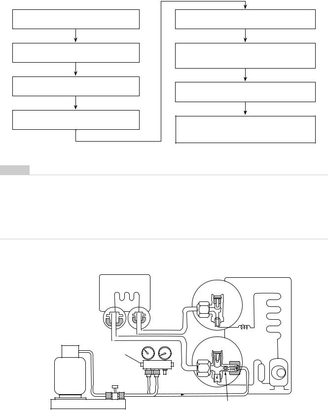
Fig. 2-4-1 Configuration of refrigerant charging
(Hydro unit)
(Outdoor unit)
Open
Refrigerant cylinder (with siphon)
Check valve
Open
Open Close
Open/close valve for charging
Service port
Electronic balance for refrigerant charging
11

NOTE
•Make sure that the setting is appropriate so that liquid can be charged.
•A cylinder with siphon enables liquid to be charged without the cylinder turned upside down.
[Cylinder with siphon]
Gauge manifold
Outdoor unit
Refrigerant cylinder
[Cylinder without siphon]
Gauge manifold
Outdoor unit
Siphon pipe
Refrigerant cylinder
Electronic balance |
Electronic balance |
NOTE
•Because R410A is HFC mixed refrigerant, charging with gas changes the charged refrigerant composition, causing the equipment characteristics to change.
12

2-5. Brazing of pipes
2-5-1. Materials of brazing
Silver brazing metal
Silver brazing metal is an alloy mainly composed of silver and copper.
It uses iron, copper, or copper alloy, and is relatively expensive though it excels in soldering.
Phosphor bronze brazing metal
Phosphor bronze brazing metal is generally used to join copper or copper alloy.
Low temperature brazing metal
Low temperature brazing metal is generally called solder, and is an alloy of tin and lead. Do not use it for refrigerant piping because its adhesive capacity is low.
NOTE
•Phosphor bronze brazing metal tends to react with sulfur, producing a fragile compound water solution. This may cause gas leakage. Therefore, use other type of brazing metal at a hot spring resort or similar place, and coat the surface with coatings.
•To braze the pipe again while performing service work, use the same type of brazing metal.
2-5-2. Flux
Why flux is necessary
•Removing all the oxide film and any foreign matter on the metal surface assists the flow of brazing metal.
•Flux prevents the metal surface from being oxidized in the course of brazing.
•Reducing the brazing metal's surface tension enables the brazing metal to adhere for better metal processing.
Characteristics of flux
•The activation temperature of flux matches the brazing temperature.
•A wide effective temperature range makes flux hard to carbonize.
•It is easy to remove slag after brazing.
•The corrosive action to the treated metal and brazing metal is minimum.
•The good performance of flux gives no harm to a human body.
Since flux works in a complicated manner as described above, select an appropriate type of flux according to metal treatment type, brazing metal and brazing method, or other conditions.
Type of flux
•Non-corrosive flux
It is generally a compound of borax and boric acid. It is effective when brazing temperature is higher than 800 °C.
•Active solvent
Most of this type of flux is generally used for silver brazing.
It features the increase of oxide film while moving the capability to the borax-boric acid compound to add compounds such as potassium fluoride, potassium chloride, or sodium fluoride.
Piping materials for brazing and brazing metal / flux
Piping material |
Brazing metal to be |
Flux to be used |
|
used |
|
Copper - Copper |
Phosphor copper |
Do not use |
|
|
|
Copper - Iron |
Silver |
Paste flux |
|
|
|
Iron - Iron |
Silver |
Vapour flux |
|
|
|
NOTE
•Do not enter flux into the refrigerant cycle.
•If chlorine contained in the flux remains within the pipe, the lubricating oil deteriorates. Because of this, use a flux that does not contain chlorine.
•When adding water to the flux, use water that does not contains chlorine. (e.g. distilled water or ionexchange water)
•Remove the flux after brazing.
2-5-3. Brazing
Brazing must be performed by a person qualified and experienced with theoretical knowledge since the operation requires sophisticated techniques.
Perform brazing while flowing dry nitrogen gas (N2) to prevent oxide film from forming during brazing application to the inside of the pipe.
NOTE
• Never use gas other than nitrogen gas.
Brazing method to prevent oxidation
1)Attach a reducing valve and a flow meter to the nitrogen cylinder.
2)Use a copper pipe to direct the piping material, and attach the flow meter to the balance.
3)Apply a mark to the clearance between the piping material and the copper pipe filled with nitrogen to prevent the back flow of the nitrogen gas.
4)If the nitrogen gas flows out, be sure to keep open the piping end.
13

5)Use the reducing valve to adjust the nitrogen gas flow speed to 0.05 m3/hour or 0.02 MPa (0.2 kgf/cm2).
6)After the steps above, keep the nitrogen gas flowing until the pipe cools down to a certain extent. (Temperature where the pipe is cool enough to be touched by hands)
7)Remove the flux completely after brazing.
Fig 2-5-1
Prevention of oxidation during brazing
M Flow meter
Stop valve
Nitrogen gas cylinder
From nitrogen cylinder
Pipe |
Nitrogen gas |
Robber plug
14

3 |
Specifications |
|
|
|
||
|
|
|
|
|
|
|
Unit name |
|
Hydro unit |
|
HWS-803XWHM3-E, 803XWHT6-E, 803XWHD6-E, 803XWHT9-E |
||
|
|
|
|
|
|
|
|
|
Outdoor unit |
|
HWS-803H-E |
|
|
Heating capacity *1 (kW) |
|
|
8.0 |
|
||
|
|
|
|
|
||
Cooling capacity *2 (kW) |
|
|
6.0 |
|
||
|
|
|
|
|||
Variable range of compressor frequency |
|
10 - 70 Hz |
|
|||
|
|
|
|
|
||
Power source |
|
|
|
Single phase 50Hz 220 - 230V |
||
Operation mode |
|
|
Heating |
|
Cooling |
|
|
|
|
|
|
|
|
Electric characteristic *1 *2 |
Hydro unit |
Current (A) |
0.98 |
|
0.46 |
|
|
|
|
|
|
|
|
|
|
|
Power (kW) |
0.101 |
|
0.097 |
|
|
|
|
|
|
|
|
|
|
Power factor (%) |
91.5 |
|
91.7 |
|
|
Outdoor unit |
Current (A) |
7.64 |
|
8.90 |
|
|
|
Power (kW) |
1.719 |
|
2.033 |
|
|
|
|
|
|
|
|
|
|
Power factor (%) |
97.8 |
|
99.3 |
|
|
|
|
|
|
|
|
|
Total |
Starting current (A) |
8.62 |
|
9.36 |
|
|
|
|
|
|
|
Operating noise *1 *2 *4 |
Hydro unit (dB(A)) |
|
29 |
|
29 |
|
|
|
Outdoor unit (dB(A)) |
|
49 |
|
49 |
|
|
|
|
|
|
|
Coefficient of performance *1 *2 |
|
|
4.40 |
|
2.82 |
|
|
|
|
|
|
|
|
Hydro unit |
|
Outer dimension |
Height (mm) |
925 |
|
|
|
|
|
|
|
|
|
|
|
|
Width (mm) |
525 |
|
|
|
|
|
Depth (mm) |
355 |
|
|
|
|
|
|
|
|
|
|
|
Net weight (kg) |
|
50 |
|
|
|
|
|
|
|
||
|
|
Color |
|
Silky shade (Munsell 1Y8.5/0.5) |
||
|
|
|
|
|
|
|
|
|
Remote controller |
Height (mm) |
120 |
|
|
|
|
Outer dimension *3 |
|
|
|
|
|
|
Width (mm) |
120 |
|
||
|
|
|
|
|||
|
|
|
Depth (mm) |
16 |
|
|
|
|
|
|
|
|
|
|
|
Circulating pump |
Motor output (W) |
125 (MAX) |
|
|
|
|
|
|
|
|
|
|
|
|
Flow rate (L/min) |
22.9 |
|
17.2 |
|
|
|
|
|
|
|
|
|
|
Type |
Non-self-suction centrifugal pump |
||
|
|
Heat exchanger |
|
Plate-type heat exchange |
||
|
|
|
|
|
|
|
Outdoor unit |
|
Outer dimension |
Height (mm) |
890 |
|
|
|
|
|
|
|
|
|
|
|
|
Width (mm) |
900 |
|
|
|
|
|
|
|
|
|
|
|
|
Depth (mm) |
320 |
|
|
|
|
Net weight (kg) |
|
63 |
|
|
|
|
Color |
|
Silky shade (Munsell 1Y8.5/0.5) |
||
|
|
|
|
|
|
|
|
|
Compressor |
Motor output (W) |
1400 |
|
|
|
|
|
|
|
||
|
|
|
Type |
Twin rotary type with DC-inverter variable speed control |
||
|
|
|
|
|
|
|
|
|
|
Model |
DA220A2F-22L |
|
|
|
|
Fan motor |
Standard air capacity (m3/min) |
50.0 |
|
|
|
|
|
Motor output (W) |
60 |
|
|
|
|
|
|
|||
Refrigerant piping |
Connection method |
|
Flare connection |
|||
|
|
|
|
|
|
|
|
|
Hydro unit |
Liquid |
Ø9.52 |
|
|
|
|
|
Gas |
Ø15.9 |
|
|
|
|
|
|
|
|
|
|
|
Outdoor unit |
Liquid |
Ø9.52 |
|
|
|
|
|
|
|
|
|
|
|
|
Gas |
Ø15.9 |
|
|
|
|
|
|
|
|
|
|
|
Maximum length (m) |
|
30 |
|
|
|
|
Maximum chargeless length (m) |
30 |
|
||
|
|
Maximum height difference (m) |
±30 |
|
||
|
|
|
|
|
|
|
|
|
Minimum length (m) |
|
5 |
|
|
|
|
|
|
|
|
|
Refrigerant |
|
Refrigerant name |
|
R410A |
|
|
|
|
|
|
|
|
|
|
|
Charge amount (kg) |
|
1.8 |
|
|
Water piping |
|
Pipe diameter |
|
R1 1/4 |
|
|
|
|
|
|
|
|
|
|
|
Maximum length (m) |
|
None (Need the flow rate 13 |
/min or more) |
|
|
|
|
|
|
||
|
|
Maximum height difference (m) |
±7 |
|
||
|
|
|
|
|
||
|
|
Maximum working water pressure (kPa) |
300 |
|
||
Operating temperature range |
Hydro unit (°C) |
|
5-32 |
|
||
|
|
Outdoor unit (°C) |
|
-20-43 |
|
|
|
|
|
|
|
||
Operating humidity range |
Hydro unit (%) |
|
15-85 |
|
||
|
|
|
|
|
|
|
|
|
Outdoor unit (%) |
|
15-100 |
|
|
|
|
|
|
|||
Wiring connection |
Power wiring |
|
3 wires: including ground line (Outdoor unit) |
|||
|
|
Connecting line |
|
4 wires: including ground line |
||
|
|
|
|
|
|
|
*1 Heating performance measurement conditions: outside air temperature 7 °C, water supply temperature 30 °C, outlet temperature 35 °C, refrigerant piping length 7.5 m (no height difference).
*2 Cooling performance measurement conditions: outside air temperature 35 °C, water supply temperature 12 °C, outlet temperature 7 °C, refrigerant piping length 7.5 m (no height difference).
*3 • The remote controller should be shipped with the hydro unit.
• Use two 1.5-meter wires to connect the hydro unit with the remote controller.
*4 The outdoor unit operating noise is measured at the point of 1m away from the unit back surface centre and 1m high from the ground. The hydro unit operating noise is measured at the point of 1m away from the unit front surface centre.
The value of the operating noise varies depending on room structure where the unit is installed. *5 Do not leave the hydro unit at 5 °C or below.
*6 Check the water piping for leakage under the maximum operating pressure.
15

Unit name |
Hydro unit |
|
HWS-1403XWHM3-E, 1403XWHT6-E, 1403XWHD6-E, 1403XWHT9-E |
||||||
|
Outdoor unit |
|
HWS-1103H-E |
|
HWS-1403H-E |
||||
Heating capacity *1 (kW) |
|
|
|
11.2 |
|
14.0 |
|
||
|
|
|
|
|
|
|
|
||
Cooling capacity *2 (kW) |
|
|
|
10.0 |
|
11.0 |
|
||
|
|
|
|
|
|
|
|||
Variable range of compressor frequency |
|
|
10 - 60Hz |
|
10 - 70 Hz |
|
|||
|
|
|
|
|
|
|
|
|
|
Power source |
|
|
|
|
Single phase 50Hz 220 - 230V |
|
|||
Operation mode |
|
|
Heating |
|
Cooling |
|
Heating |
|
Cooling |
|
|
|
|
|
|
|
|
|
|
Electric characteristic *1 *2 |
Hydro unit |
Current (A) |
0.63 |
|
0.61 |
|
0.67 |
|
0.63 |
|
|
|
|
|
|
|
|
|
|
|
|
Power (kW) |
0.135 |
|
0.130 |
|
0.145 |
|
0.135 |
|
|
|
|
|
|
|
|
|
|
|
|
Power factor (%) |
93.2 |
|
92.7 |
|
94.0 |
|
93.2 |
|
Outdoor unit |
Current (A) |
9.94 |
|
14.88 |
|
13.37 |
|
17.47 |
|
|
Power (kW) |
2.215 |
|
3.39 |
|
2.965 |
|
3.945 |
|
|
|
|
|
|
|
|
|
|
|
|
Power factor (%) |
96.9 |
|
99.1 |
|
96.4 |
|
98.1 |
|
|
|
|
|
|
|
|
|
|
|
Total |
Starting current (A) |
10.57 |
|
15.49 |
|
14.04 |
|
18.10 |
|
|
|
|
|
|
|
|
|
|
Operating noise *1 *2 *4 |
Hydro unit (dB(A)) |
|
29 |
|
29 |
|
29 |
|
29 |
|
Outdoor unit (dB(A)) |
|
49 |
|
49 |
|
51 |
|
51 |
|
|
|
|
|
|
|
|
|
|
Coefficient of performance *1 *2 |
|
|
4.77 |
|
2.84 |
|
4.50 |
|
2.70 |
|
|
|
|
|
|
|
|
|
|
Hydro unit |
Outer dimension |
Height (mm) |
|
|
|
925 |
|
|
|
|
|
|
|
|
|
|
|
|
|
|
|
Width (mm) |
|
|
|
525 |
|
|
|
|
|
Depth (mm) |
|
|
|
355 |
|
|
|
|
|
|
|
|
|
|
|
|
|
|
Net weight (kg) |
|
|
|
|
54 |
|
|
|
|
|
|
|
|
|
|
|||
|
Color |
|
|
|
Silky shade (Munsell 1Y8.5/0.5) |
|
|||
|
|
|
|
|
|
|
|
|
|
|
Remote controller |
Height (mm) |
|
|
|
120 |
|
|
|
|
Outer dimension *3 |
|
|
|
|
|
|
|
|
|
Width (mm) |
|
|
|
120 |
|
|
||
|
|
|
|
|
|
|
|||
|
|
Depth (mm) |
|
|
|
16 |
|
|
|
|
|
|
|
|
|
|
|
||
|
Circulating pump |
Motor output (W) |
|
|
|
190 (MAX) |
|
||
|
|
|
|
|
|
|
|
|
|
|
|
Flow rate (L/min) |
32.1 |
|
28.9 |
|
40.1 |
|
31.5 |
|
|
|
|
|
|
|
|
|
|
|
|
Type |
|
|
Non-self-suction centrifugal pump |
|
|||
|
Heat exchanger |
|
|
|
Plate-type heat exchange |
|
|||
|
|
|
|
|
|
|
|
|
|
Outdoor unit |
Outer dimension |
Height (mm) |
|
|
|
1340 |
|
|
|
|
|
|
|
|
|
|
|
|
|
|
|
Width (mm) |
|
|
|
900 |
|
|
|
|
|
|
|
|
|
|
|
|
|
|
|
Depth (mm) |
|
|
|
320 |
|
|
|
|
Net weight (kg) |
|
|
|
|
93 |
|
|
|
|
Color |
|
|
|
Silky shade (Munsell 1Y8.5/0.5) |
|
|||
|
|
|
|
|
|
|
|
|
|
|
Compressor |
Motor output (W) |
|
|
|
2500 |
|
|
|
|
|
|
|
||||||
|
|
Type |
Twin rotary type with DC-inverter variable speed control |
||||||
|
|
|
|
|
|
|
|||
|
|
Model |
|
|
DA422A3F-25M |
|
|||
|
Fan motor |
Standard air capacity (m3/min) |
|
|
|
103.0 |
|
|
|
|
|
Motor output (W) |
|
|
|
100 × 2 |
|
|
|
|
|
|
|
|
|
|
|||
Refrigerant piping |
Connection method |
|
|
|
Flare connection |
|
|||
|
|
|
|
|
|
|
|
|
|
|
Hydro unit |
Liquid |
|
|
|
Ø9.52 |
|
|
|
|
|
Gas |
|
|
|
Ø15.9 |
|
|
|
|
|
|
|
|
|
|
|
|
|
|
Outdoor unit |
Liquid |
|
|
|
Ø9.52 |
|
|
|
|
|
|
|
|
|
|
|
|
|
|
|
Gas |
|
|
|
Ø15.9 |
|
|
|
|
|
|
|
|
|
|
|
|
|
|
Maximum length (m) |
|
|
|
|
30 |
|
|
|
|
Maximum chargeless length (m) |
|
|
|
30 |
|
|
||
|
Maximum height difference (m) |
|
|
|
±30 |
|
|
||
|
|
|
|
|
|
|
|
|
|
|
Minimum length (m) |
|
|
|
|
5 |
|
|
|
|
|
|
|
|
|
|
|
||
Refrigerant |
Refrigerant name |
|
|
|
|
R410A |
|
||
|
|
|
|
|
|
|
|
|
|
|
Charge amount (kg) |
|
|
|
|
2.7 |
|
|
|
Water piping |
Pipe diameter |
|
|
|
|
R1 1/4 |
|
||
|
|
|
|
|
|
||||
|
Maximum length (m) |
|
|
None (Need the flow rate 17.5 /min or more) |
|
||||
|
|
|
|
|
|
|
|
||
|
Maximum height difference (m) |
|
|
|
±7 |
|
|
||
|
|
|
|
|
|
|
|
||
|
Maximum working water pressure (kPa) |
|
|
|
300 |
|
|
||
Operating temperature range |
Hydro unit (°C) |
|
|
|
|
5-32 |
|
|
|
|
Outdoor unit (°C) |
|
|
|
|
-20-43 |
|
|
|
|
|
|
|
|
|
|
|
|
|
Operating humidity range |
Hydro unit (%) |
|
|
|
|
15-85 |
|
|
|
|
|
|
|
|
|
|
|
|
|
|
Outdoor unit (%) |
|
|
|
|
15-100 |
|
|
|
|
|
|
|
|
|
||||
Wiring connection |
Power wiring |
|
|
3 wires: including ground line (Outdoor unit) |
|
||||
|
Connecting line |
|
|
|
4 wires: including ground line |
|
|||
|
|
|
|
|
|
|
|
|
|
*1 Heating performance measurement conditions: outside air temperature 7 °C, water supply temperature 30 °C, outlet temperature 35 °C, refrigerant piping length 7.5 m (no height difference).
*2 Cooling performance measurement conditions: outside air temperature 35 °C, water supply temperature 12 °C, outlet temperature 7 °C, refrigerant piping length 7.5 m (no height difference).
*3 • The remote controller should be shipped with the hydro unit.
• Use two 1.5-meter wires to connect the hydro unit with the remote controller.
*4 The outdoor unit operating noise is measured at the point of 1m away from the unit back surface centre and 1m high from the ground. The hydro unit operating noise is measured at the point of 1m away from the unit front surface centre.
The value of the operating noise varies depending on room structure where the unit is installed. *5 Do not leave the hydro unit at 5 °C or below.
*6 Check the water piping for leakage under the maximum operating pressure.
16

Unit name |
Hydro unit |
|
HWS-1403XWHM3-E, 1403XWHT6-E, 1403XWHD6-E, 1403XWHT9-E |
||||||||||
|
Outdoor unit |
|
HWS-1103H8(R)-E |
|
HWS-1403H8(R)-E |
|
HWS-1603H8(R)-E |
||||||
Heating capacity *1 (kW) |
|
|
|
11.2 |
|
|
14.0 |
|
16.0 |
|
|||
|
|
|
|
|
|
|
|
|
|
|
|||
Cooling capacity *2 (kW) |
|
|
|
10.0 |
|
|
11.0 |
|
13.0 |
|
|||
|
|
|
|
|
|
|
|||||||
Variable range of compressor frequency |
|
10 - 60Hz |
|
10 - 60 Hz |
|
10 - 70 Hz |
|||||||
|
|
|
|
|
|
|
|
|
|
|
|
|
|
Power source |
|
|
|
|
|
|
3 phase 50Hz 380 - 400V |
|
|
|
|||
Operation mode |
|
|
Heating |
|
Cooling |
|
Heating |
|
Cooling |
|
Heating |
|
Cooling |
|
|
|
|
|
|
|
|
|
|
|
|
|
|
Electric characteristic *1 *2 |
Hydro unit |
Current (A) |
0.63 |
|
0.61 |
|
0.67 |
|
0.63 |
|
0.69 |
|
0.66 |
|
|
|
|
|
|
|
|
|
|
|
|
|
|
|
|
Power (kW) |
0.135 |
|
0.130 |
|
0.145 |
|
0.135 |
|
0.150 |
|
0.140 |
|
|
|
|
|
|
|
|
|
|
|
|
|
|
|
|
Power factor (%) |
93.2 |
|
92.7 |
|
94.0 |
|
93.2 |
|
94.5 |
|
92.3 |
|
Outdoor unit |
Current (A) |
4.03 |
|
5.65 |
|
5.23 |
|
6.50 |
|
5.95 |
|
7.50 |
|
|
Power (kW) |
2.255 |
|
3.39 |
|
3.065 |
|
3.945 |
|
3.570 |
|
4.660 |
|
|
|
|
|
|
|
|
|
|
|
|
|
|
|
|
Power factor (%) |
81.1 |
|
87.0 |
|
84.9 |
|
88.0 |
|
87.0 |
|
90.0 |
|
|
|
|
|
|
|
|
|
|
|
|
|
|
|
Total |
Starting current (A) |
4.66 |
|
6.26 |
|
6.06 |
|
7.13 |
|
4.26 |
|
8.16 |
|
|
|
|
|
|
|
|
|
|
|
|
|
|
Operating noise *1 *2 *4 |
Hydro unit (dB(A)) |
|
29 |
|
29 |
|
29 |
|
29 |
|
29 |
|
29 |
|
Outdoor unit (dB(A)) |
|
49 |
|
50 |
|
51 |
|
51 |
|
52 |
|
52 |
|
|
|
|
|
|
|
|
|
|
|
|
|
|
Coefficient of performance *1 *2 |
|
|
4.69 |
|
2.84 |
|
4.36 |
|
2.70 |
|
4.30 |
|
2.71 |
|
|
|
|
|
|
|
|
|
|
|
|
|
|
Hydro unit |
Outer dimension |
Height (mm) |
|
|
|
|
|
925 |
|
|
|
|
|
|
|
|
|
|
|
|
|
|
|
|
|
|
|
|
|
Width (mm) |
|
|
|
|
|
525 |
|
|
|
|
|
|
|
Depth (mm) |
|
|
|
|
|
355 |
|
|
|
|
|
|
|
|
|
|
|
|
|
|
|
|
|
|
|
|
Net weight (kg) |
|
|
|
|
|
|
54 |
|
|
|
|
|
|
|
|
|
|
|
|
|
|
|
||||
|
Color |
|
|
|
|
Silky shade (Munsell 1Y8.5/0.5) |
|
|
|
||||
|
|
|
|
|
|
|
|
|
|
|
|
|
|
|
Remote controller |
Height (mm) |
|
|
|
|
|
120 |
|
|
|
|
|
|
Outer dimension *3 |
|
|
|
|
|
|
|
|
|
|
|
|
|
Width (mm) |
|
|
|
|
|
120 |
|
|
|
|
||
|
|
|
|
|
|
|
|
|
|
|
|||
|
|
Depth (mm) |
|
|
|
|
|
16 |
|
|
|
|
|
|
|
|
|
|
|
|
|
|
|
|
|||
|
Circulating pump |
Motor output (W) |
|
|
|
|
190 (MAX) |
|
|
|
|||
|
|
|
|
|
|
|
|
|
|
|
|
|
|
|
|
Flow rate (L/min) |
32.1 |
|
28.9 |
|
40.1 |
|
31.5 |
|
45.8 |
|
37.3 |
|
|
|
|
|
|
|
|
|
|
|
|||
|
|
Type |
|
|
Non-self-suction centrifugal pump |
|
|||||||
|
Heat exchanger |
|
|
|
|
|
Plate-type heat exchange |
|
|
|
|||
|
|
|
|
|
|
|
|
|
|
|
|
|
|
Outdoor unit |
Outer dimension |
Height (mm) |
|
|
|
|
|
1340 |
|
|
|
|
|
|
|
|
|
|
|
|
|
|
|
|
|
|
|
|
|
Width (mm) |
|
|
|
|
|
900 |
|
|
|
|
|
|
|
|
|
|
|
|
|
|
|
|
|
|
|
|
|
Depth (mm) |
|
|
|
|
|
320 |
|
|
|
|
|
|
Net weight (kg) |
|
|
|
|
|
|
93 |
|
|
|
|
|
|
Color |
|
|
|
|
Silky shade (Munsell 1Y8.5/0.5) |
|
|
|
||||
|
|
|
|
|
|
|
|
|
|
|
|
|
|
|
Compressor |
Motor output (W) |
|
|
|
|
|
2500 |
|
|
|
|
|
|
|
|
|
|
|
||||||||
|
|
Type |
|
Twin rotary type with DC-inverter variable speed control |
|
||||||||
|
|
|
|
|
|
|
|
|
|
|
|||
|
|
Model |
|
|
|
|
DA422A3F-27M |
|
|
|
|||
|
Fan motor |
Standard air capacity (m3/min) |
|
|
|
|
|
103.0 |
|
|
|
|
|
|
|
Motor output (W) |
|
|
|
100 × 2 |
|
|
|
|
|||
|
|
|
|
|
|
|
|
|
|
|
|||
Refrigerant piping |
Connection method |
|
|
|
|
|
Flare connection |
|
|
|
|||
|
|
|
|
|
|
|
|
|
|
|
|||
|
Hydro unit |
Liquid |
|
|
|
Ø9.52 |
|
|
|
|
|||
|
|
Gas |
|
|
|
Ø15.9 |
|
|
|
|
|||
|
|
|
|
|
|
|
|
|
|
|
|||
|
Outdoor unit |
Liquid |
|
|
|
Ø9.52 |
|
|
|
|
|||
|
|
|
|
|
|
|
|
|
|
|
|||
|
|
Gas |
|
|
|
Ø15.9 |
|
|
|
|
|||
|
|
|
|
|
|
|
|
|
|
|
|
|
|
|
Maximum length (m) |
|
|
|
|
|
|
30 |
|
|
|
|
|
|
Maximum chargeless length (m) |
|
|
|
|
|
30 |
|
|
|
|
||
|
Maximum height difference (m) |
|
|
|
|
|
±30 |
|
|
|
|
||
|
|
|
|
|
|
|
|
|
|
|
|
|
|
|
Minimum length (m) |
|
|
|
|
|
|
5 |
|
|
|
|
|
|
|
|
|
|
|
|
|
|
|
|
|||
Refrigerant |
Refrigerant name |
|
|
|
|
|
R410A |
|
|
|
|||
|
|
|
|
|
|
|
|
|
|
|
|
|
|
|
Charge amount (kg) |
|
|
|
|
|
|
2.7 |
|
|
|
|
|
Water piping |
Pipe diameter |
|
|
|
|
|
R1 1/4 |
|
|
|
|||
|
|
|
|
|
|
|
|||||||
|
Maximum length (m) |
|
|
|
None (Need the flow rate 17.5 /min or more) |
|
|||||||
|
|
|
|
|
|
|
|
|
|
|
|
||
|
Maximum height difference (m) |
|
|
|
|
|
±7 |
|
|
|
|
||
|
|
|
|
|
|
|
|
|
|
|
|
||
|
Maximum working water pressure (kPa) |
|
|
|
|
|
300 |
|
|
|
|
||
Operating temperature range |
Hydro unit (°C) |
|
|
|
|
|
|
5-32 |
|
|
|
|
|
|
Outdoor unit (°C) |
|
|
|
|
-20-43 |
|
|
|
|
|||
|
|
|
|
|
|
|
|
|
|
|
|
|
|
Operating humidity range |
Hydro unit (%) |
|
|
|
|
|
|
15-85 |
|
|
|
|
|
|
|
|
|
|
|
|
|
|
|
|
|||
|
Outdoor unit (%) |
|
|
|
|
15-100 |
|
|
|
|
|||
|
|
|
|
|
|
|
|||||||
Wiring connection |
Power wiring |
|
|
|
5 wires: including ground line (Outdoor unit) |
|
|||||||
|
Connecting line |
|
|
|
|
4 wires: including ground line |
|
|
|
||||
|
|
|
|
|
|
|
|
|
|
|
|
|
|
*1 Heating performance measurement conditions: outside air temperature 7 °C, water supply temperature 30 °C, outlet temperature 35 °C, refrigerant piping length 7.5 m (no height difference).
*2 Cooling performance measurement conditions: outside air temperature 35 °C, water supply temperature 12 °C, outlet temperature 7 °C, refrigerant piping length 7.5 m (no height difference).
*3 • The remote controller should be shipped with the hydro unit.
• Use two 1.5-meter wires to connect the hydro unit with the remote controller.
*4 The outdoor unit operating noise is measured at the point of 1m away from the unit back surface centre and 1m high from the ground. The hydro unit operating noise is measured at the point of 1m away from the unit front surface centre.
The value of the operating noise varies depending on room structure where the unit is installed. *5 Do not leave the hydro unit at 5 °C or below.
*6 Check the water piping for leakage under the maximum operating pressure.
17

4 |
Outside Drawing |
|
|
|
|
|
||
4-1. |
Hydro unit |
|
|
|
|
|
|
|
HWS-803XWHM3-E, 803XWHT6-E, 803XWHD6-E, 803XWHT9-E |
||||||||
HWS-1403XWHM3-E, 1403XWHT6-E, 1403XWHD6-E, 1403XWHT9-E |
||||||||
|
|
|
|
|
525 |
|
19.5 |
|
|
|
|
|
|
|
|
|
|
|
|
|
|
|
|
|
352 |
|
|
|
2-dia.12x17 long hole |
|
|
|
9 |
|
|
40.5 |
371.5 |
(for dia.8-10 anchor bolt) |
72.5 |
380 |
72.5 |
|
|
|
B leg part |
|
|
||||||
355 |
40 |
Anchor bolt |
|
|
|
|||
|
|
20 |
|
|
long hole pitch |
|
|
|
|
|
|
|
|
|
|
|
|
|
925 |
960 |
long hole pitch |
|
|
|
|
|
|
|
|
Anchor bolt |
|
|
|
Manometer |
|
|
|
|
|
|
|
|
||
|
|
|
|
|
|
|
Remote controler |
|
|
54 |
20 |
|
|
|
|
|
|
40.5 |
|
A |
leg part |
40 |
2-dia.12x17 U-shape hole |
|
|
|
|
|
|
|
|||||
|
|
|
|
(for dia.8-10 anchor bolt) |
|
|
||
|
|
|
|
|
|
|
||
|
|
|
|
|
19.5 |
116 |
Hot water outlet |
|
|
|
|
|
|
connecting pipe 1 1/4" |
|||
|
|
|
|
|
|
|
||
|
|
|
259 |
|
|
|
186.5 |
135.5 |
|
|
|
|
|
|
|
37.5 |
158 |
|
|
Drain nipple |
|
|
|
|
Gas line dia.15.88 |
|
|
|
Water inlet |
|
|
|
|
Liquid line dia.9.52 |
|
|
|
connecting pipe 1 1/4" |
144.5 |
|
59.5 |
|||
|
|
|
|
|
|
|||
|
|
|
|
|
309.5 |
|
|
|
|
|
|
|
|
18 |
|
|
|

4-2. |
Outdoor unit |
|
|
|
|
|
|
|
|
|
|
|
|
|
||||||
HWS-803H-E |
|
|
|
|
|
|
|
|
|
|
|
|
|
|
|
|
|
|
|
|
|
Description |
|
|
|
38 knockout hole |
|
|
|
|
|
|
|
|
|
|
|
|
|
|
|
|
Name |
Refrigerant piping outlet |
Indoor and outdoor |
connecting line outlet |
Power source intake hole |
Mounting bolt hole |
( 12 17 U-shape hole) |
|
|
|
|
|
|
|
|
|
64 |
|
|
|
|
|
|
|
|
|
|
|
95 |
55 |
12 |
|
|
|
|||||||
|
|
|
|
|
|
|
B |
|
|
|
|
|
|
|
|
|
|
|
|
|
|
|
12 |
|
|
|
|
portion |
|
|
|
|
|
|
890 |
24 |
|
|
|
|
|
|
|
|
|
|
|
|
|
|
|
|
|
|
|
|
|
|
|
|||
|
|
|
|
|
|
|
of |
|
|
|
|
|
|
|
|
|
|
|
|
|
|
|
Mounting bolt hole |
( 12 17 long hole) |
|
40 |
|
portionA Details |
|
|
320 |
|
|
|
|
|
|
|
|
400 |
|
|
|
|
|
|
|
|
|
|
|
|
|
|
80 |
151 |
|
|||||
|
|
|
|
|
|
|
30 |
|
|
|
|
|
18 |
|
||||||
|
|
|
|
|
|
|
of |
|
|
|
|
|
|
|
|
|
94 |
|
|
|
|
|
|
|
|
|
|
|
|
|
|
|
|
|
95 |
55 |
|
|
|
|
|
|
|
|
|
|
|
|
Details |
|
|
|
|
|
|
|
|
|
|
|
||
|
|
|
|
|
40 |
|
|
|
Refrigerant liquid |
|
( 9.5 flare) |
Refrigerant gas |
connection ( 15.9 flare) |
|
|
|
|
|
|
|
hole( 25 burring hole) |
|
|
|
|
|
|
|
|
|
|
|
|
|
|
|
|||||
|
|
|
|
|
|
|
|
|
connection |
255 |
|
|
|
|
|
|||||
|
|
|
|
|
|
|
|
|
247 |
|
|
|
|
|
||||||
Portion B |
|
|
54 |
|
|
39 |
96 |
|
155 |
18 |
|
|
|
|||||||
|
|
48 |
|
|
|
95 |
55 |
|
|
|
||||||||||
|
|
|
|
|
|
|
|
|
||||||||||||
|
|
|
|
|
|
|
|
80 |
135 |
|
|
|||||||||
Drain |
|
170 |
|
Portion A |
|
|
|
|
|
|
|
|
|
|
|
|
|
|||
|
34 |
|
|
|
|
|
|
|
|
|
|
|
178 178 178 |
|
|
|
||||
|
|
|
|
|
|
|
|
|
|
|
|
|
|
|
|
|
||||
|
200 60 Air inlet |
46 |
75 |
|
Air outlet |
|
150 600 |
900 |
|
|
|
|
|
|
|
|
|
|
||
380 |
|
|
|
383 |
550 |
|
|
|
|
|
|
518 |
327 |
of piping |
||||||
|
|
inlet |
|
|
|
|
88 burring hole) |
|
52 |
|
|
|
|
|
|
mounting hole 60 |
3 embossed) 68 |
|
Knockout for lower part |
|
|
|
Air |
|
|
|
|
|
|
|
|
534 |
165 |
|
|||||||
|
|
128 |
|
118 |
74 |
|
|
|
|
|
|
581 |
148 |
|
||||||
|
|
|
|
|
|
|
|
|
|
|
|
|
||||||||
|
5.17 |
|
365 |
|
5.17 |
|
|
|
|
|
|
|
|
|||||||
|
|
|
|
|
|
|
|
|
|
|
|
|
|
|
7 |
|||||
|
|
|
|
|
|
|
|
|
|
|
|
|
|
|
|
|
Optional |
|
65 |
|
|
|
|
|
|
|
|
|
Drainhole ( 20 |
|
|
|
|
|
|
|
|
(12- |
7 |
Z arrowview |
|
|
|
|
|
|
|
|
|
|
|
|
|
|
|
|
|
83 |
||||
|
|
|
|
|
|
|
|
5- |
|
|
|
|
|
|
|
|
|
|
|
|
|
|
|
|
|
|
|
|
|
|
|
|
|
19 |
|
|
|
|
|
|
|
HWS-1103H-E, 1403H-E, 1103H8(R)-E, 1403H8(R)-E, 1603H8(R)-E |
|
|
|
|
|
|
|
|
|||||||||||||||||
Description |
|
|
|
38 knockout hole |
|
|
|
|
|
|
|
|
|
|
|
|
|
|
|
|
|
|
|
|
|
Name |
outdoorandIndoor |
|
2 Power source intake hole |
Mounting bolt hole |
( 12 17 U-shape hole) |
|
|
|
|
|
|
|
|
|
|
|
|
|
|
|
|
|
|
||
Refrigerantpipingoutlet |
1 connectingoutletline |
|
|
|
|
|
|
|
|
|
|
1 |
95 |
55 |
12 64 |
|
|
|
|
||||||
|
|
|
|
|
|
|
B |
|
|
|
|
|
|
|
|
|
|
|
|
|
|
|
|
|
|
|
|
|
12 |
|
|
|
portion |
|
|
|
|
|
|
|
1340 |
|
|
24 |
|
|
|
|
|
|
|
|
|
|
|
|
|
|
|
|
|
|
|
|
|
|
|
|
|
|
|
|
|
|
|||
|
|
|
|
|
|
|
of |
|
|
|
|
|
|
|
|
|
|
|
|
|
|
|
|
|
|
|
|
bolt hole |
long hole) |
|
40 |
|
Details |
|
|
320 |
|
|
|
|
|
|
|
|
|
|
|
400 |
|
|
|
|
|
|
|
|
|
|
|
|
|
|
|
|
|
|
|
80 |
151 |
|
|
|
|||||
|
|
Mounting |
( 12 17 |
|
|
|
Details of portion A |
|
|
|
Refrigerant liquid connection |
|
Refrigerant gas connection |
|
30 |
2 2 |
1 |
|
|
18 |
|
|
|
|
|
|
|
|
|
|
|
|
|
|
|
|
|
94 |
|
|
|
|
|
||||||||
|
|
|
|
|
|
|
|
|
|
|
|
|
|
|
|
|
|
||||||||
|
|
|
|
|
|
|
|
|
|
|
95 |
55 |
|
|
|
|
|
|
|||||||
hole( 25 burring hole) |
|
|
40 |
|
|
|
|
( 9.5 flare) |
( 15.9 flare) |
613 |
|
|
|
|
|
|
|
|
|||||||
|
|
|
|
|
|
|
|
|
|
|
|
|
|
|
|||||||||||
|
|
|
|
|
|
|
605 |
155 |
|
|
|
|
|
|
|||||||||||
|
|
|
|
|
|
|
|
|
|
|
|
|
|
||||||||||||
Portion B |
|
54 |
|
39 |
96 |
|
1 |
95 |
55 |
80 18 |
|
|
|
|
|
||||||||||
|
|
|
|
|
|
|
|
|
|
||||||||||||||||
|
48 |
|
|
|
|
|
|
|
|
|
|||||||||||||||
|
|
|
|
|
|
135 |
|
|
Z |
|
|||||||||||||||
Drain |
|
|
170 |
|
Portion A |
|
|
|
|
|
|
|
|
|
|
|
|
|
|
|
|
|
|||
|
|
34 |
|
|
|
|
|
|
|
|
|
|
|
|
|
178 178 178 |
|
|
|
|
|
||||
|
200 60 Air inlet |
46 |
75 |
|
Air outlet |
383 70 |
600 |
900 |
550 |
|
|
|
|
|
|
|
|
518 |
|
|
|
|
|||
380 |
|
|
|
|
|
|
|
|
|
|
|
327 |
|
|
|
||||||||||
|
|
|
Airinlet |
|
|
|
|
|
150 |
|
52 |
|
581 |
|
74 |
581 |
|
|
70 |
60 |
68 |
|
|
|
piping |
|
|
|
128 |
|
118 |
|
|
|
|
|
|
|
|
|
|
|
Optional mounting hole |
(24- 3 embossed) |
|
|
Knockout for lower partof |
||||
|
|
|
|
|
|
|
|
|
|
|
534 |
|
121 |
534 |
|
|
85 |
|
|
|
|||||
|
|
|
|
|
74 |
|
|
|
|
|
|
|
|
|
|
|
|
|
|||||||
|
|
|
|
|
|
|
|
|
|
|
|
|
|
655 |
|
360 |
|
|
|
|
|
||||
5.17 |
|
|
365 |
|
|
5.17 |
88 burring hole) |
|
|
|
|
|
|
|
|
|
|
||||||||
|
|
|
|
|
|
|
|
|
|
|
|
|
|
|
|
||||||||||
|
|
|
|
|
|
|
|
|
|
|
|
|
|
|
|
|
|
|
|
|
|
||||
|
|
|
|
|
|
|
|
|
|
( 20 |
|
|
|
|
|
|
|
|
|
|
|
7 |
7 |
65 |
view |
|
|
|
|
|
|
|
|
|
|
|
|
|
|
|
|
|
|
|
|
|
|
|
|||
|
|
|
|
|
|
|
|
|
|
Drain hole |
|
|
|
|
|
|
|
|
|
|
|
83 |
|
|
Z arrow |
|
|
|
|
|
|
|
|
|
|
5- |
|
|
|
|
|
|
|
|
|
|
|
|
|
|
|
|
|
|
|
|
|
|
|
|
|
|
|
|
|
20 |
|
|
|
|
|
|
|
|
|
|
|

4-3. Hot water cylinder
HWS-3001CSHM3-E(-UK) |
HWS-2101CSHM3-E(-UK) |
550 |
550 |
595 |
595 |
|
Specification |
|
for UK only |
2066.6 |
2040 |
|
Specification |
|
for UK only |
|
1497.6 |
1474
HWS-1501CSHM3-E(-UK)
 550
550
595
1114 |
Specification |
|
for UK only |
||
|
1090
21

5 Wiring Diagram
5-1. Hydro Unit
 WARNING
Perform the grounding from the earth terminal in the terminal block of the outdoor unit. 
 CAUTION
Electric shock may happen. Don't touch the electric parts.
Color identification
BLK : BLACK |
BLU : BLUE |
|
|
BRW : BROWN |
GRN : GREEN |
|
|
GRY : GRAY |
ORN : ORANGE |
|
|
PNK : PINK |
RED : RED |
|
|
WHI : WHITE YEL : YELLOW |
|
|
|
|
YEL |
9 |
9 |
|
BLU |
|
8 |
|
7 |
7 |
|
|
BRW |
|
6 |
|
5 |
5 |
|
|
|
|
4 |
|
|
|
3 |
|
WHI |
|
2 |
|
1 |
1 |
|
|
WHI 3 |
3 |
|
|
RED |
|
2 |
|
1 |
1 |
|
CN10
(WHI)
CR10 |
RY |
|
CR11 |
10 |
|
RY |
|
|
|
11 |
|
CR12 |
RY |
|
|
12 |
CN02 |
CR13 |
RY |
(WHI) |
|
13 |
|
CN01
(WHI)
Relay p.c.board
(MCC-1431)
F01 (5A)
WPM N N L L
*Option
|
|
|
Remote |
|
|
|
|
|
|
|
|
|
|
|
|
|
|
|
|
|
|
|
|
|
|
|
||
|
|
|
controller |
|
|
|
|
|
|
|
|
|
|
|
|
|
|
|
|
|
|
|
|
|
|
|
||
|
|
|
(HWS-AMS11E) |
TC |
|
TWI |
TWO |
THO |
|
|
|
|
|
|
|
|
|
|
|
|
|
|
|
|
|
|||
Remote |
|
A B |
|
|
|
|
*Option |
|
|
|
|
Symbol |
|
|
Parts name |
|
Symbol |
Parts name |
||||||||||
|
|
|
|
|
|
|
|
|
|
|
|
|
|
|
|
|
||||||||||||
controller |
|
|
|
|
|
|
|
|
|
|
|
|
|
|
|
WPM |
|
|
|
|
Water pump motor |
|
TC |
Water heat exchanger temperature sensor |
||||
(HWS-AMS11E) |
|
|
|
|
|
|
|
|
|
|
|
LPS |
TTW |
|
TFI |
|
|
|
|
|
||||||||
|
|
|
|
|
|
|
|
|
|
|
|
3WV |
|
|
|
|
|
3-way valve (local) |
|
TWI |
Water heat exchanger inlet temperature sensor |
|||||||
|
A B |
|
|
|
|
|
|
|
|
|
|
|
|
|
|
|
|
|
|
|
||||||||
|
|
|
|
|
|
|
|
|
|
|
|
1 2 3 4 |
|
|
|
|
2WV |
|
|
|
|
|
2-way valve (local) |
|
TWO |
Water heat exchanger outlet temperature sensor |
||
GRY WHI |
|
TB 07 7A 7B |
|
|
|
|
|
|
|
|
A B |
|
|
|
|
|
|
|
|
|||||||||
|
|
|
|
|
|
|
|
|
2 3 4 |
|
|
|
MIXV |
|
|
|
|
Mixing valve (local) |
|
THO |
Backup heater outlet temperature sensor |
|||||||
|
|
|
|
|
|
|
|
|
|
|
|
|
|
2 3 4 |
|
6A 6B |
6C 6D |
|
BH |
|
|
|
|
|
Booster heater |
|
TTW |
Hot water cylinder temperature sensor |
|
|
|
|
1 2 |
|
|
|
|
|
|
|
|
2 3 4 |
|
TB 06 |
RY01~RY06 |
|
|
Relay01~Relay06 |
|
TFI |
Floor heating inlet temperature sensor |
||||||
|
|
|
|
1 |
2 |
|
|
|
|
|
|
|
|
|
|
BRW BRW |
|
|
LPS |
|
|
|
|
|
Low pressure sensor |
|
TB |
Terminal block |
|
|
|
GRY |
WHI |
BLK BLK |
BLK |
BLK |
BLK BLK |
BLK |
BLK |
WHI BLK |
RED |
|
RED |
RED |
Backup heater1, 2, 3 |
Heater AC230V, 3kW |
|
|
|
||||||||
|
|
|
|
|
|
|
|
|
|
|
|
|
*Option p.c.board |
|||||||||||||||
|
|
|
1 |
|
3 |
1 2 |
1 |
3 |
1 2 |
1 |
3 |
1 |
2 |
2 |
|
1 2 |
1 |
3 |
|
|
|
|
|
|
|
|
|
|
|
|
|
1 2 3 |
1 2 |
1 2 3 |
1 2 |
1 2 3 |
1 |
2 |
1 2 3 |
4 |
1 2 |
1 2 3 |
|
|
|
|
|
|
|
|
|
|
|||||
|
|
|
CN41 |
CN203 |
CN204 |
CN205 |
CN206 |
CN207 |
CN212 |
CN214 |
CN213 |
|
1 |
1 |
GRN |
1 |
1 |
Relay |
K1 |
4 |
Boiler control O/P |
|||||||
|
|
|
(BLU) |
(YEL) |
(BRW) |
(RED) |
(WHI) |
(BLU) |
(WHI) |
|
(WHI) |
(WHI) |
CN208 |
GRN |
3 |
|||||||||||||
|
|
|
|
|
|
|
|
|
|
|
|
|
|
|
|
|
|
|
2 |
2 |
GRN |
2 |
2 |
p.c.board |
|
2 |
|
|
|
|
|
|
|
|
|
|
|
|
|
|
|
|
|
|
|
|
|
(BLU) |
3 |
3 |
3 |
3 |
K2 |
Alerm O/P |
|||
|
|
|
|
|
|
|
|
|
|
|
|
|
|
|
|
|
|
|
|
4 |
4 |
GRN |
4 |
4 |
(MCC-1217) |
1 |
||
|
|
|
|
|
|
|
|
|
|
|
|
|
|
|
|
|
|
|
|
PJ20 |
|
|
||||||
|
|
|
|
|
|
|
|
|
|
|
|
|
|
|
|
|
|
|
|
|
|
|
|
|
|
TB1 |
|
|
|
|
|
|
|
|
|
|
|
|
|
|
|
|
|
|
|
|
|
|
|
|
|
|
|
|
|
|
|
|
|
6 |
|
|
|
|
|
|
|
P.C.board |
|
|
|
|
|
|
1 |
1 |
GRN |
1 |
1 |
Relay |
K1 |
4 |
Compressor operation |
|||
|
RED |
5 5 |
|
|
|
|
|
|
|
|
|
|
|
|
CN209 |
2 |
2 |
GRN |
2 |
2 |
|
3 |
O/P |
|||||
5 5 |
BLU |
4 4 |
CN501 |
|
|
|
|
(MCC-1511) |
|
|
|
|
(GRN) |
3 |
3 |
GRN |
3 |
3 |
p.c.board |
K2 |
2 |
Defrost O/P |
||||||
ORN |
|
|
|
|
|
|
|
|
|
GRN |
(MCC-1217) |
1 |
||||||||||||||||
4 4 |
GRN |
3 3 |
(YEL) |
|
|
|
|
|
|
|
|
|
|
|
|
|
|
|
|
4 |
4 |
|
4 |
4 |
PJ20 |
|
TB1 |
|
3 3 |
2 2 |
|
|
|
|
|
|
|
|
|
|
|
|
|
|
|
|
|
|
|
|
|
|
|
|
|||
|
|
|
|
|
|
|
|
|
|
|
|
|
|
|
|
|
|
|
|
|
|
|
|
|
||||
2 2 |
BRW |
1 1 |
|
|
|
|
|
|
|
|
|
|
|
|
|
|
|
|
|
|
|
|
|
|
|
|
|
|
1 1 |
|
|
|
|
|
|
|
|
|
|
|
|
|
|
|
|
|
|
|
1 |
1 |
YEL |
1 |
1 |
Photocoupler input |
|
3 |
|
|
|
|
|
|
|
|
|
1 |
|
|
|
|
|
|
|
|
|
|
CN210 |
2 |
2 |
YEL |
2 |
2 |
|
Emergency stop I/P |
||
|
|
|
|
|
|
|
|
|
|
|
|
|
|
|
|
|
|
YEL |
p.c.board |
|
2 |
|||||||
|
|
|
|
|
|
|
|
|
|
|
|
|
|
|
|
|
|
|
(RED) |
3 |
3 |
YEL |
3 |
3 |
(MCC-1214) |
|
1 |
|
|
|
|
|
|
|
|
|
|
|
|
|
|
|
|
|
|
|
|
|
4 |
4 |
|
4 |
4 |
PJ17 |
|
TB1 |
|
BLK |
|
|
|
|
|
|
SW01 |
|
|
|
|
|
|
SW14 |
|
|
1 |
1 |
YEL |
1 |
1 |
|
|
|
|
|||
|
|
|
|
|
|
|
|
|
|
|
|
|
|
OFF |
|
|
|
Photocoupler input |
|
3 |
|
|||||||
|
BLU |
|
|
|
|
|
|
|
|
|
|
|
|
|
|
|
|
CN211 |
2 |
2 |
YEL |
2 |
2 |
|
Cooling thermostat I/P |
|||
|
3 3 |
|
|
|
|
|
SW02 |
|
|
|
|
|
|
|
|
|
YEL |
p.c.board |
|
2 |
||||||||
|
|
CN603 |
|
RY601 |
|
|
|
|
|
|
|
ON |
|
|
(BLK) |
3 |
3 |
YEL |
3 |
3 |
(MCC-1214) |
|
1 |
Heating thermostat I/P |
||||
|
BRW 1 1 |
(YEL) |
|
|
|
ON |
|
|
|
|
|
|
|
|
|
|
4 |
4 |
|
4 |
4 |
PJ17 |
|
TB1 |
|
|||
|
|
|
|
|
|
|
|
|
|
|
|
|
|
|
|
|
|
|
|
|
|
|
|
|
||||
|
|
|
|
|
|
A2 |
05 |
A1 |
RED 3 3 |
CN601 |
RY600 |
|||
|
|
|
|
|
|
|
|
1 |
1 |
|||||
|
|
|
|
|
|
|
RY |
|
WHI |
|
|
(RED) |
|
|
|
|
|
|
|
|
|
|
|
YEL |
7 7 |
|
RY602 |
||
|
|
|
|
|
|
|
|
|
WHI |
5 5 |
|
|||
|
|
|
WHI |
|
|
|
|
|
|
|
|
3 |
|
RY603 |
|
WHI |
WHI |
|
|
|
|
|
RED 1 1 |
CN602 |
|||||
YEL |
BLU |
BRW |
RED |
WHI YEL |
RED |
PNK WHI ORN |
|
|
|
|
|
|
|
|
|
|
|
|
|
|
(WHI) |
|
|||||||
51 52 53 54 55 56 57 58 59 TB 05 |
41 42 43 44 TB 04 |
|
|
|
|
|
|
RY604 |
||||||
WPM 2WV |
BH |
3WV |
|
MIXV |
|
|
|
|
|
|
|
|
||
|
|
|
|
Type 1 |
|
Type 1 |
|
|
|
|
|
|
CN604 |
|
|
|
|
(2-wire spring return) |
RED |
(3-wire SPDT type) |
|
|
|
|
|
|
(BLU) |
|
|
|
|
|
RED |
WHI YEL |
PNK WHI ORN |
|
|
|
|
|
|
7 |
5 |
|
|
|
|
|
|
|
|
|
|
|
|
|
|
7 |
5 |
|
|
|
57 58 59 TB 05 |
41 42 43 44 TB 04 |
|
|
|
|
|
|
RED |
WHI |
||
|
|
|
|
|
|
|
|
|
|
|
||||
|
*See DIP SW13_1 |
|
|
|
|
|
|
|
|
|
|
5 |
||
|
|
|
|
|
|
|
|
|
|
|
|
|
|
|
|
|
|
|
3WV |
|
MIXV |
|
|
|
|
|
|
2 4 |
6 |
|
|
|
|
Type 2 |
|
Type 2 |
|
|
|
|
|
|
||
|
|
|
(3-wire SPST type) |
|
(3-wire SPST type) |
|
|
|
|
|
|
PNK |
RED |
|
|
|
|
|
Type 3 |
|
|
|
|
|
|
|
|
ORN |
|
|
|
|
(3-wire SPDT type) |
|
|
|
|
|
|
|
|
|
|
|
RED |
WHI |
GRY |
|
|
|
|
|
|
|
|
|
|
|
|
11 12 13 TB 01 |
|
|
|
|
|
Thermal protector |
Backup heater 1 |
|||||||
|
|
|
|
|
|
|
|
|
(Single operation) |
|
|
|||
1 2 3 Outdoor unit |
|
|
|
|
95 |
5 |
|
|
|
|
||||
|
|
|
|
Thermal protector |
Backup heater 2 |
|||||||||
|
|
|
|
|
|
|
|
|
(Single operation) |
|
|
|||
|
|
|
|
|
|
|
|
|
95 |
5 |
|
|
|
|
Power supply |
|
|
|
|
220 - 230V~ 50Hz |
1L1 3L2 |
|
||
or |
|
|
|
RY05 |
380 - 400V~ 50Hz |
|
|
|
|
|
|
|
|
|
|
2T1 4T2 |
|
||
|
BRW |
BLU |
F1, F2 |
|
|
F1 |
F2 |
Fuse |
|
|
AC250V |
|||
|
|
|
|
T30A |
BRW BLU |
BRW |
BLU |
YEL/GRN |
|
TB 03 |
31 32 |
L |
N |
*Option |
|
1 2 |
Power supply |
||
|
|
220 - 230V~ 50Hz |
||
Hot water cylinder
|
|
|
|
|
|
|
Thermal protector Backup heater 3 |
1L1 3L2 5L3 RY02 |
|
|
(Single operation)95 5 |
||||
1L1 3L2 5L3 |
|||||||
|
|
|
|
|
|
|
RY04 |
2T1 4T2 6T3 GRY |
2T1 4T2 6T3 |
||||||
BRW |
BLU |
F5 |
|
|
BLK |
BLU |
BLU |
F3 |
F4 |
F6 |
F7 |
F8 |
F3~8 |
||
|
|
|
|
|
|
||
|
|
|
|
|
|
Fuse |
|
|
|
|
|
|
|
AC250V |
|
BRW |
BLU |
BLK |
BLU |
GRY |
BLU |
T30A |
|
|
|
||||||
|
|
L1 L2 L3 N TB 02 |
HWS-803XWHT9-E |
||||
|
|
|
|
|
|
|
|
|
|
|
|
|
|
|
HWS-1403XWHT9-E |
|
|
Power supply |
|
HWS-1403XWHT9TR |
|||
|
380 - 400V 3N~ 50Hz |
|
|
||||
|
1 |
2 |
3 |
4 |
|
|
|
|
|
|
|
|
|
|
|
|
|
|
|
|
1 |
1 |
YEL |
RY |
2 2 |
|
|
|
|
|
|
|
|
|
|
|
|
|
|
|
|
|
|
|
|
|
|
|
|
|
CN200 |
GRN |
7 01 8 |
|
|
Flow switch |
|
|
|||||
|
|
|
SW10 |
SW11 |
SW12 |
SW13 |
(RED) |
2 |
2 |
RED |
|
1 |
1 |
|
|
|
|
|
|||||||||||||
|
|
|
3 |
3 |
|
|
|
|
|
|
|
|
|||||||||||||||||||
|
|
|
ON |
|
|
|
ON |
|
|
|
ON |
|
|
|
ON |
|
|
|
CN201 |
1 1 |
BLK |
1 1 |
Pressure switch |
|
|
|
|||||
|
|
|
|
|
|
|
|
|
|
|
|
|
|
|
|
|
|
|
(WHI) |
BLK |
3 3 |
1. The one-dot chain line indicates |
|||||||||
|
|
|
1 |
2 |
3 |
4 |
1 |
2 |
3 |
4 |
1 |
2 |
3 |
4 |
1 |
2 |
3 |
4 |
|
|
2 |
2 |
|
|
4.15MPa |
||||||
|
|
|
|
|
1 1 BLK |
|
|
|
|
|
wiring at the local site, and the |
||||||||||||||||||||
|
|
|
|
|
|
|
SW06 |
|
|
|
|
|
|
|
|
|
(YEL) |
|
|
|
(auto) 75 |
5 |
|||||||||
|
|
|
|
|
|
|
|
|
|
|
|
|
|
|
|
|
2 |
|
BLK |
|
|
dashed |
line indicates accessories |
||||||||
|
|
|
|
|
|
|
|
|
|
|
|
|
|
|
|
|
|
|
CN202 |
|
|
|
|
Thermal protector |
|
|
|
||||
|
|
|
|
|
|
|
ON |
|
|
|
SW07 |
|
|
|
|
|
|
3 |
3 |
|
|
|
|
|
|
sold |
separately and service wires, |
||||
|
|
|
|
|
|
|
|
|
|
|
|
|
|
|
|
|
1 |
1 |
BRW |
|
|
|
|
|
respectively. |
||||||
|
|
|
|
|
|
|
1 |
2 |
|
|
|
|
|
|
|
|
|
|
|
|
2 |
2 |
BRW |
|
|
|
|
|
2. , and |
indicates the terminal |
|
|
|
|
|
|
|
|
|
|
|
|
|
|
|
|
|
|
|
|
CN102 |
3 |
3 |
RED |
|
|
|
|
|
board and the numberals ndicate the |
|||
|
|
|
|
|
|
|
|
|
|
|
|
|
|
|
|
|
|
|
(WHI) |
4 |
4 |
RED |
|
|
|
|
|
terminal numbers. |
|||
|
|
|
|
|
|
|
|
|
|
|
|
|
|
|
|
|
|
|
ORN |
|
|
|
|
|
|||||||
|
|
|
|
|
|
|
|
|
|
|
|
|
|
|
|
|
|
|
|
|
5 |
5 |
ORN |
|
|
|
|
|
3. |
indicates P.C. board. |
|
RY605 |
|
RY606 |
|
|
RY607 |
|
|
|
|
|
|
|
|
|
|
6 |
6 |
|
|
|
|
|
|||||||||
|
|
|
|
|
|
|
|
|
|
|
CN101 |
|
|
|
|
|
Transformer |
* Be sure to fix the electric |
|||||||||||||
|
|
|
|
|
|
|
|
|
|
|
|
|
|
|
|
|
|
|
1 |
1 |
WHI |
|
|
||||||||
|
|
|
|
|
|
|
|
|
|
|
|
|
|
|
|
|
|
|
(WHI) |
|
|
|
|
|
parts |
cover surely with screws. |
|||||
|
|
|
|
|
|
|
|
|
|
|
|
|
|
|
|
|
|
|
|
|
|
|
|
|
|
|
|
|
|
||
|
|
|
|
|
|
|
|
|
|
|
|
|
|
|
|
|
|
|
|
|
|
|
WHI |
|
|
|
|
|
(Otherwise water enters into the box |
||
|
|
|
|
|
|
|
|
|
|
|
|
|
|
|
|
|
|
|
F100 |
|
3 |
3 |
|
|
|
|
|
resulting in malfunction.) |
|||
|
CN605 |
|
|
|
CN606 |
|
|
|
|
CN305 |
CN100 |
|
Fuse |
|
P100 BLK |
|
|
|
|
|
|
|
|
||||||||
|
|
|
|
|
|
|
|
|
T5A |
|
|
|
|
|
|
|
|
|
|||||||||||||
|
|
(YEL) |
|
|
|
(BLU) |
|
|
|
|
(GRN) |
(WHI) |
|
250V~ |
|
|
|
|
|
|
|
|
|
|
|
|
|||||
3 |
1 |
|
|
1 |
|
3 |
|
|
1 |
3 |
|
|
3 |
1 |
5 |
|
3 |
1 |
|
|
|
|
|
|
|
|
|
|
|
|
|
3 |
1 |
|
|
1 |
|
3 |
|
|
1 |
3 |
|
|
3 |
|
|
|
3 |
1 |
|
|
|
|
|
|
|
|
|
|
|
|
|
YEL |
BLK |
|
WHI |
ORN |
|
WHI |
PNK |
|
|
GRY |
|
|
|
WHI |
RED |
* |
|
|
|
|
|
|
* |
|
|
|
|
|
|||
|
|
|
|
6 |
|
A2 |
8 |
|
6 |
A1 |
|
|
|
|
|
|
|
|
1 |
HWS-803XWHT6-E : Installed |
|
1 HWS-803XWHT6TR : Installed |
|
||||||||
7 |
|
|
|
|
|
|
|
|
|
|
|
|
|
|
HWS-1403XWHT6-E : Installed |
|
|
HWS-1403XWHT6TR : Installed |
|
||||||||||||
|
RY |
|
RY |
RY |
|
|
RY |
|
|
|
|
|
|
|
|
|
|
|
|
||||||||||||
|
|
|
|
|
|
|
|
|
|
|
|
|
|
HWS-803XWHD6-E : Installed |
|
|
|
HWS-1403XWHT9TR : Installed |
|
||||||||||||
RY |
|
|
01 |
|
|
02 |
03 |
|
|
04 |
|
|
|
|
|
|
|
|
|
|
|
|
|
|
|||||||
06 |
|
|
|
4 |
|
A1 |
7 |
|
4 |
A2 |
|
|
|
|
|
|
|
|
|
|
HWS-1403XWHD6-E : Installed |
|
|
|
HWS-803XWHM3TR : Not installed |
||||||
8 |
|
|
|
|
|
|
|
|
|
|
|
|
|
|
|
|
|
|
|
|
HWS-803XWHT9-E : Installed |
|
|
|
HWS-1403XWHM3TR : Not installed |
||||||
|
|
|
WHI |
|
|
WHI |
|
|
|
|
|
|
|
|
|
|
HWS-1403XWHT9-E : Installed |
|
|
|
|
|
|
|
|||||||
|
|
|
|
|
|
|
|
|
|
|
|
|
|
|
|
|
|
|
|
|
|
|
|||||||||
|
|
|
|
|
|
|
|
*1 |
|
|
|
|
|
|
|
|
|
|
|
|
HWS-803XWHM3-E : Not installed |
|
|
|
|
|
|
||||
|
|
|
|
|
|
|
|
|
|
|
|
|
|
|
|
|
|
|
|
HWS-1403XWHM3-E : Not installed |
|
|
|
|
|
||||||
|
|
|
|
Thermal protector |
Backup heater 1 |
|
|
|
|
|
(Single operation) |
|
|
|
|
|
|
95 |
5 |
|
|
|
|
|
Thermal protector |
Backup heater 2 |
|
|
|
|
|
(Single operation) |
|
|
|
|
|
|
95 |
5 |
|
|
|
RY02 |
|
|
|
|
1L1 3L2 5L3 |
1L1 3L2 5L3 |
|
||||
|
|
|
|
|
RY04 |
|
2T1 4T2 6T3 |
2T1 4T2 6T3 |
|
||||
BRW |
BLU |
|
BLK |
BLU |
|
|
|
|
|
|
|||
F3 |
F4 |
F5 |
F6 |
F3~6 |
|
|
|
|
|
|
|
|
|
|
|
|
|
Fuse |
|
|
|
|
|
|
AC250V |
|
|
BRW |
BLU |
BLK |
BLU |
T30A |
|
|
|
|
|
||||
|
|
L1 L2 L3 N TB 02 HWS-803XWHT6-E |
||||
|
|
|
|
|
HWS-1403XWHT6-E |
|
|
|
Power supply |
HWS-803XWHT6TR |
|||
|
380 - 400V 3N~ 50Hz |
HWS-1403XWHT6TR |
||||
|
|
Thermal protector |
Backup heater 1 |
|||
|
|
(Single operation) |
|
|||
|
|
|
95 |
5 |
|
|
1L1 3L2 5L3 |
RY02 |
|
|
|||
2T1 4T2 6T3 |
|
|
|
|
||
BRW |
BLU |
|
|
|
|
|
F3 |
F4 |
F3,F4 |
|
|
|
|
|
|
|
|
|
||
|
|
Fuse |
|
|
|
|
|
|
AC250V |
|
|
||
BRW |
BLU |
T30A |
|
|
|
|
|
|
|
|
|
||
L |
|
N TB 02 |
HWS-803XWHM3-E |
|||
|
|
|
|
|
HWS-1403XWHM3-E |
|
Power supply |
|
|
HWS-803XWHM3TR |
|||
220 - 230V~ 50Hz |
|
HWS-1403XWHM3TR |
||||
|
|
|
|
Thermal protector |
Backup heater 1 |
|
|
|
|
|
(Single operation) |
|
|
|
|
|
|
95 |
5 |
|
|
|
|
|
Thermal protector |
Backup heater 2 |
|
|
|
|
|
(Single operation) |
|
|
|
|
|
|
95 |
5 |
|
|
|
RY02 |
|
|
|
|
1L1 3L2 5L3 |
1L1 3L2 5L3 |
|
||||
|
|
|
|
|
RY04 |
|
2T1 4T2 6T3 |
2T1 4T2 6T3 |
|
||||
BRW |
BLU |
|
BLK |
BLU |
|
|
|
|
|
|
|||
F3 |
F4 |
F5 |
F6 |
F3~6 |
|
|
|
|
|
|
|
|
|
|
|
|
|
Fuse |
|
|
|
|
|
|
AC250V |
|
|
BRW |
BLU |
BLK |
BLU |
T30A |
|
|
|
|
|
||||
|
|
L1 L2 |
L3 TB 02 HWS-803XWHD6-E |
|||
HWS-1403XWHD6-E
Power supply 220 - 230V 3~ 50Hz
22
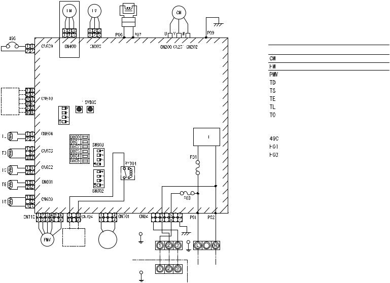
23
Reactor
Upper
R W B
(White) (White)
(Blue) (White) (White)
HMS-1103, 1403H-E only
External
input
Control board 


(Yellow) 


(White)
(White)
(Yellow) (White)
(White)
(White) |
|
(White) (White) |
W R B |
|
|
G |
|
Operating |
4-way |
|
|
power |
valve |
|
|
|
coil |
Earth screw |
|
|
|
Outdoor unit |
|
|
|
Hydro unit |
|
Red White
Earth screw
Power supply
single phase 220-230V
50Hz
Symbol |
Item name |
|
Compressor |
|
Fan motor |
|
Pulse motor valve coil |
|
|
|
Discharge temperature sonsor |
|
Suction temperature sensor |
|
Heat exchange sensor 1 |
|
Heat exchange sensor 2 |
|
Outdoor temperature sensor |
4F |
Linetilter |
20SF |
4-way valve coil |
|
Compressor case thermostat |
|
Fuse 25 A, 250 VAC |
|
Fuse 10A, 250 VAC |
1. indicates a terminal plate. The number inside indicates the terminal number.
2.The double-dashed line indicates a local wiring while the dashed line indicates an optional accessory or service wiring.
3.  indicates a printed board.
4. For the hydro unit circuit, see the hydro unit wiring diagram.
E-1403H-HWS E,-1103H-HWS E,-803H-HWS |
phase (Single Unit Outdoor .2-5 |
|
Type) |
Earth screw

5-3. Outdoor Unit (3 phase type)
HWS-1103H8(R)-E, -1403H8(R)-E, -1603H8(R)-E |
P.C. board |
MCC-1596 |
P.C. board |
MCC-1597 |
(1103H8R-E |
1403H8R-E |
1603H8R-E) |
only |
Hydro |
unit |


 indicates the teminal block. Alphanumeric characters in the cycle indicate terminal No.

 The two-dot chain line indicates the wiring procured locally.
indicates the P.C. board.

 For the hydro unit circuit, refer to the wiring diagram of the indoor unit.
24
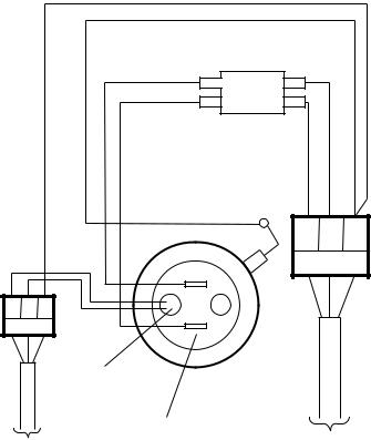
5-4. Hot Water Cylinder Unit
|
|
Double pole thermal cut out |
|
Blue |
Blue |
Green / |
Brown |
|
Yellow |
|
|
|
|
Brown |
1 2 
TB03(230V)
A B 
TB06(TTW)
TTW sensor
Hot water cylinder heater
To hydro unit
Supply 220 - 230 V from hydro unit Cable size 1.5 mm2 (minimum)
25

6 Key Electric Component Rating
6-1. Hydro Unit
HWS-803XWHM3-E, T6-E, D6-E, T9-E
No. |
Component name |
|
Model name |
|
Type name |
Rating |
||
|
|
|
|
|||||
M3-E |
T6-E |
D6-E |
T9-E |
|||||
|
|
|
|
|||||
|
|
|
|
|
|
|
|
|
1 |
Circulating pump |
O |
O |
O |
O |
UPS025-65 K 130 |
AC230 V 0.54 A (MAX) |
|
|
|
|
|
|
|
|
|
|
2 |
Backup heater 6 kW |
O |
O |
O |
|
– |
AC 400 V (3N) 6 kW (AC230 V 3 kW |
|
|
|
compatible) |
||||||
|
|
|
|
|
|
|
||
|
|
|
|
|
|
|
|
|
3 |
Backup heater 9 kW |
|
|
|
O |
– |
AC400V (3N) 9 kW |
|
|
|
|
|
|
|
|
|
|
|
Water heat exchange |
|
|
|
|
|
10 kΩ (25°C) |
|
4 |
temperature sensor |
O |
O |
O |
O |
– |
|
|
|
(TC sensor) |
|
|
|
|
|
|
|
|
|
|
|
|
|
|
|
|
5 |
Water inlet temperature sensor |
O |
O |
O |
O |
– |
10 kΩ (25°C) |
|
(TWI sensor) |
|
|||||||
|
|
|
|
|
|
|
||
|
|
|
|
|
|
|
|
|
6 |
Water outlet temperature sensor |
O |
O |
O |
O |
– |
10 kΩ (25°C) |
|
(TWO sensor) |
|
|||||||
|
|
|
|
|
|
|
||
|
|
|
|
|
|
|
|
|
|
Heater outlet water temperature |
|
|
|
|
|
10 kΩ (25°C) |
|
7 |
sensor |
O |
O |
O |
O |
– |
|
|
|
(THO sensor) |
|
|
|
|
|
|
|
|
|
|
|
|
|
|
|
|
8 |
Floor inlet temperature sensor |
O |
O |
O |
O |
– |
10 kΩ (25°C) |
|
(TFI sensor) |
|
|||||||
|
|
|
|
|
|
|
||
|
|
|
|
|
|
|
|
|
9 |
Pressure switch |
O |
O |
O |
O |
– |
Operating pressure 4.15 MPa +0 -0.3 |
|
|
MPa |
|||||||
|
|
|
|
|
|
|
||
|
|
|
|
|
|
|
|
|
10 |
Low pressure sensor |
O |
O |
O |
O |
– |
Operating pressure 0.20 MPa |
|
|
|
|
|
|
|
|
|
|
11 |
Bimetal thermostat (auto) |
O |
O |
O |
O |
– |
Operating temperature 75±3°C DC42 V |
|
|
/ 0.2 A |
|||||||
|
|
|
|
|
|
|
||
|
|
|
|
|
|
|
|
|
12 |
Bimetal thermostat (single |
O |
O |
O |
O |
– |
Operating temperature 95±5°C |
|
operation) |
AC250 V / 16 A |
|||||||
|
|
|
|
|
|
|||
|
|
|
|
|
|
|
|
|
13 |
Flow switch |
O |
O |
O |
O |
– |
Operating flowing quantity 13 /min |
|
|
|
|
|
|
|
|
|
|
14 |
Output board (OP) |
OP |
OP |
OP |
OP |
TCB-PCIN3E |
AC230 V 0.5 A DC24 V 1 A |
|
|
|
|
|
|
|
|
|
|
15 |
Input board (OP) |
OP |
OP |
OP |
OP |
TCB-PCM03E |
Contact input |
|
|
|
|
|
|
|
|
|
|
16 |
Remote control (Main) |
O |
O |
O |
O |
HWS-AMS11E |
|
|
|
|
|
|
|
|
|
|
|
17 |
Remote control (Sub) |
OP |
OP |
OP |
OP |
HWS-AMS11E |
|
|
|
|
|
|
|
|
|
|
|
|
Water 3-way valve terminal |
|
|
|
|
|
AC230 V 0.1 A |
|
18 |
|
O |
O |
O |
O |
– |
2Wire, 3Wire SPST, SPDT type |
|
|
|
|
|
|
|
|
mountable |
|
|
|
|
|
|
|
|
|
|
19 |
Water 2-way valve terminal |
O |
O |
O |
O |
– |
AC230 V 0.1 A 2Wire type mountable |
|
|
|
|
|
|
|
|
|
|
20 |
Mixing valve terminal |
O |
O |
O |
O |
– |
AC230 V 0.1 A |
|
|
3Wire SPST, SPDT type mountable |
|||||||
|
|
|
|
|
|
|
||
|
|
|
|
|
|
|
|
|
21 |
Circulating pump terminal |
O |
O |
O |
O |
– |
AC230 V 1.0 A |
|
|
|
|
|
|
|
|
|
|
22 |
Booster heater terminal |
O |
O |
O |
O |
– |
AC230 V 1.0 A |
|
|
|
|
|
|
|
|
|
|
23 |
Fuse |
O |
O |
O |
O |
– |
AC 250 V 30 A |
|
|
|
|
|
|
|
|
|
|
O ········· Applied
OP·······Optional accessory
26
HWS-1403XWHM3-E, T6-E, D6-E, T9-E
No. |
Component name |
|
Model name |
|
Type name |
Rating |
||
|
|
|
|
|||||
M3-E |
T6-E |
D6-E |
T9-E |
|||||
|
|
|
|
|||||
|
|
|
|
|
|
|
|
|
1 |
Circulating pump |
O |
O |
O |
O |
UPS25-80 130 |
AC230 V 0.83 A (MAX) |
|
|
|
|
|
|
|
|
|
|
2 |
Backup heater 6 kW |
O |
O |
O |
|
– |
AC 400 V (3N) 6 kW (AC230 V 3kW |
|
|
|
compatible) |
||||||
|
|
|
|
|
|
|
||
|
|
|
|
|
|
|
|
|
3 |
Backup heater 9 kW |
|
|
|
O |
– |
AC 400 V (3N) 9 kW |
|
|
|
|
|
|
|
|
|
|
|
Water heat exchange |
|
|
|
|
|
10 kΩ (25°C) |
|
4 |
temperature sensor |
O |
O |
O |
O |
– |
|
|
|
(TC sensor) |
|
|
|
|
|
|
|
|
|
|
|
|
|
|
|
|
5 |
Water inlet temperature sensor |
O |
O |
O |
O |
– |
10 kΩ (25°C) |
|
(TWI sensor) |
|
|||||||
|
|
|
|
|
|
|
||
|
|
|
|
|
|
|
|
|
6 |
Water outlet temperature sensor |
O |
O |
O |
O |
– |
10 kΩ (25°C) |
|
(TWO sensor) |
|
|||||||
|
|
|
|
|
|
|
||
|
|
|
|
|
|
|
|
|
|
Heater outlet water temperature |
|
|
|
|
|
10 kΩ (25°C) |
|
7 |
sensor |
O |
O |
O |
O |
– |
|
|
|
(THO sensor) |
|
|
|
|
|
|
|
|
|
|
|
|
|
|
|
|
8 |
Floor inlet temperature sensor |
O |
O |
O |
O |
– |
10 kΩ (25°C) |
|
(TFI sensor) |
|
|||||||
|
|
|
|
|
|
|
||
|
|
|
|
|
|
|
|
|
9 |
Pressure switch |
O |
O |
O |
O |
– |
Operating pressure 4.15 MPa +0 -0.3 |
|
|
MPa |
|||||||
|
|
|
|
|
|
|
||
|
|
|
|
|
|
|
|
|
10 |
Low pressure sensor |
O |
O |
O |
O |
– |
Operating pressure 0.20 MPa |
|
|
|
|
|
|
|
|
|
|
11 |
Thermal protector (auto) |
O |
O |
O |
O |
– |
Operating temperature 75±3°C DC42 V |
|
|
/ 0.2 A |
|||||||
|
|
|
|
|
|
|
||
|
|
|
|
|
|
|
|
|
12 |
Thermal protector (single |
O |
O |
O |
O |
– |
Operating temperature 95±5°C AC250 |
|
operation) |
V 16 A |
|||||||
|
|
|
|
|
|
|||
|
|
|
|
|
|
|
|
|
13 |
Flow switch |
O |
O |
O |
O |
– |
Operating flowing quantity 17.5 L/min |
|
|
|
|
|
|
|
|
|
|
14 |
Output board (OP) |
OP |
OP |
OP |
OP |
TCB-PCIN3E |
AC230 V 0.5 A DC24 V 1 A |
|
|
|
|
|
|
|
|
|
|
15 |
Input board (OP) |
OP |
OP |
OP |
OP |
TCB-PCM03E |
Contact input |
|
|
|
|
|
|
|
|
|
|
16 |
Remote control (Main) |
O |
O |
O |
O |
HWS-AMS11E |
|
|
|
|
|
|
|
|
|
|
|
17 |
Remote control (Sub) |
OP |
OP |
OP |
OP |
HWS-AMS11E |
|
|
|
|
|
|
|
|
|
|
|
|
Water 3-way valve terminal |
|
|
|
|
|
AC230 V 0.1 A |
|
18 |
|
O |
O |
O |
O |
– |
2Wire, 3Wire SPST, SPDT type |
|
|
|
|
|
|
|
|
mountable |
|
|
|
|
|
|
|
|
|
|
19 |
Water 2-way valve terminal |
O |
O |
O |
O |
– |
AC230 V 0.1 A 2Wire type mountable |
|
|
|
|
|
|
|
|
|
|
20 |
Mixing valve terminal |
O |
O |
O |
O |
– |
AC230 V 0.1 A |
|
|
3Wire SPST, SPDT type mountable |
|||||||
|
|
|
|
|
|
|
||
|
|
|
|
|
|
|
|
|
21 |
Circulating pump terminal |
O |
O |
O |
O |
– |
AC230 V 1.0 A |
|
|
|
|
|
|
|
|
|
|
22 |
Booster heater terminal |
O |
O |
O |
O |
– |
AC230 V 1.0 A |
|
|
|
|
|
|
|
|
|
|
23 |
Fuse |
O |
O |
O |
O |
– |
AC 250 V 30 A |
|
|
|
|
|
|
|
|
|
|
O ········· Applied
OP·······Optional accessory
27
6-2. Outdoor Unit
HWS-803H-E
No. |
Component name |
Type name |
Rating |
|
|
|
|
1 |
Compressor |
DA220A2F-22L |
|
|
|
|
|
2 |
Outdoor fan motor |
ICF-280-A60-1 |
Output 60 W |
|
|
|
|
3 |
4-way valve coil |
VHV-01AP552B1 |
AC220 - 230 full-wave rectifier input, alive time |
|
|
10 sec or less |
|
|
|
|
|
|
|
|
|
4 |
Pulse motor valve (PMV) coil |
CAM-MD12TF-15 |
DC12 V |
|
|
|
|
5 |
Compressor case thermostat |
US-622KXTMQO-SS |
OFF: 125±4°C ON: 90±5°C |
|
|
|
|
6 |
Reactor |
CH-56 |
5.8 mH, 18.5 A |
|
|
|
|
7 |
PC board |
MCC-1571 |
Input 1Ø, AC220 - 230 V ± 10 %, |
|
|
50/60 Hz |
|
|
|
|
|
|
|
|
|
28
HWS-1103H-E, 1403H-E
No. |
Component name |
Type name |
Rating |
|
|
|
|
1 |
Compressor |
DA422A3F-25M |
|
|
|
|
|
2 |
Outdoor fan motor (x2) |
ICF-280-A100-1 |
Output 100 W |
|
|
|
|
3 |
Reactor (x2) |
CH-44 |
1.4 mH, 25 A |
|
|
|
|
4 |
4-way valve coil |
|
AC220 - 230 V full-wave rectifier input, alive time 10 sec or less |
|
|
|
|
5 |
Pulse motor valve (PMV) coil |
UKV-A038 |
DC12 V |
|
|
|
|
6 |
Board |
MCC-1560 |
Input 3Ø, AC230 V±23 V, 50/60 Hz |
|
|
|
|
7 |
Compressor case thermostat |
US-622KXTMQO-SS |
OFF = 125 ± 4 °C, ON = 90 ± 5 °C |
|
|
|
|
8 |
PC board |
MCC-1571 |
Input 1Ø, AC220 - 230 V ± 10 %, 50/60 Hz |
|
|
|
|
29
 Loading...