


FILE NO. 810-200633GR
SERVICE MANUAL
®
DVD Video Recorder
D-R265SE
The above model is classified as a green product (*1), as indicated by the underlined serial number. This Service Manual describes replacement parts for the green product. When repairing this green product, use the part(s) described in this manual and lead-free solder (*2).
For (*1) and (*2), see the next page.
TOSHIBA CORPORATION 2006 |
Published in Japan, May 2006 GREEN |

(*1) |
GREEN PRODUCT PROCUREMENT |
The EC is actively promoting the WEEE & RoHS Directives that define standards for recycling and reuse of Waste Electrical and Electronic Equipment and for the Restriction of the use of certain Hazardous Substances. From July 1, 2006, the RoHS Directive will prohibit any marketing of new products containing the restricted substances.
Increasing attention is given to issues related to the global environmental. Toshiba Corporation recognizes environmental protection as a key management tasks, and is doing its utmost to enhance and improve the quality and scope of its environmental activities. In line with this, Toshiba proactively promotes Green Procurement, and seeks to purchase and use products, parts and materials that have low environmental impacts.
Green procurement of parts is not only confined to manufacture. The same green parts used in manufacture must also be used as replacement parts.
(*2) |
LEAD-FREE SOLDER |
This product is manufactured using lead-free solder as a part of a movement within the consumer products industry at large to be environmentally responsible. Lead-free solder must be used in the servicing and repair of this product.
WARNING
This product is manufactured using lead free solder.
DO NOT USE LEAD BASED SOLDER TO REPAIR THIS PRODUCT !
The melting temperature of lead-free solder is higher than that of leaded solder by 86°F to 104°F (30°C to 40°C). Use of a soldering iron designed for lead-based solders to repair product made with lead-free solder may result in damage to the component and or BOARD being soldered. Great care should be made to ensure high-quality soldering when servicing this product — especially when soldering large components, through-hole pins, and on BOARDs — as the level of heat required to melt lead-free solder is high.

IMPORTANT SAFETY NOTICE
Proper service and repair is important to the safe, reliable operation of all TOSHIBA Equipment. The service procedures recommended by TOSHIBA and described in this service manual are effective methods of performing service operations. Some of these service special tools should be used when and as recommended.
It is important to note that this service manual contains various CAUTIONS and NOTICES which should be carefully read in order to minimize the risk of personal injury to service personnel. The possibility exists that improper service methods may damage the equipment. It also is important to understand that these CAUTIONS and NOTICES ARE NOT EXHAUSTIVE. TOSHIBA could not possibly know, evaluate and advice the service trade of all conceivable ways in which service might be done or of the possible hazardous consequences of each way. Consequently, TOSHIBA has not undertaken any such broad evaluation. Accordingly, a servicer who uses a service procedure or tool which is not recommended by TOSHIBA must first use all precautions thoroughly so that neither his safety nor the safe operation of the equipment will be jeopardized by the service method selected.
TABLE OF CONTENTS
Specifications . . . . . . . . . . . . . . . . . . . . . . . . . . . . . . . . . . . . . . . . . . . . . . . . . . . . . . . . . . . . . . . . . . . . . . . . . . 1-1-1 Laser Beam Safety Precautions. . . . . . . . . . . . . . . . . . . . . . . . . . . . . . . . . . . . . . . . . . . . . . . . . . . . . . . . . . . . 1-2-1 Important Safety Precautions. . . . . . . . . . . . . . . . . . . . . . . . . . . . . . . . . . . . . . . . . . . . . . . . . . . . . . . . . . . . . . 1-3-1 Standard Notes for Servicing . . . . . . . . . . . . . . . . . . . . . . . . . . . . . . . . . . . . . . . . . . . . . . . . . . . . . . . . . . . . . . 1-4-1 Cabinet Disassembly Instructions . . . . . . . . . . . . . . . . . . . . . . . . . . . . . . . . . . . . . . . . . . . . . . . . . . . . . . . . . . 1-5-1 How to Initialize the DVD Recorder . . . . . . . . . . . . . . . . . . . . . . . . . . . . . . . . . . . . . . . . . . . . . . . . . . . . . . . . . 1-6-1 Firmware Renewal Mode . . . . . . . . . . . . . . . . . . . . . . . . . . . . . . . . . . . . . . . . . . . . . . . . . . . . . . . . . . . . . . . . . 1-7-1 Troubleshooting . . . . . . . . . . . . . . . . . . . . . . . . . . . . . . . . . . . . . . . . . . . . . . . . . . . . . . . . . . . . . . . . . . . . . . . . 1-8-1 Function Indicator Symbols . . . . . . . . . . . . . . . . . . . . . . . . . . . . . . . . . . . . . . . . . . . . . . . . . . . . . . . . . . . . . . . 1-9-1 Block Diagrams . . . . . . . . . . . . . . . . . . . . . . . . . . . . . . . . . . . . . . . . . . . . . . . . . . . . . . . . . . . . . . . . . . . . . . . 1-10-1 Schematic Diagrams / BOARD’s and Test Points . . . . . . . . . . . . . . . . . . . . . . . . . . . . . . . . . . . . . . . . . . . . . 1-11-1 Waveforms . . . . . . . . . . . . . . . . . . . . . . . . . . . . . . . . . . . . . . . . . . . . . . . . . . . . . . . . . . . . . . . . . . . . . . . . . . . 1-12-1 Wiring Diagram . . . . . . . . . . . . . . . . . . . . . . . . . . . . . . . . . . . . . . . . . . . . . . . . . . . . . . . . . . . . . . . . . . . . . . . 1-13-1 System Control Timing Charts . . . . . . . . . . . . . . . . . . . . . . . . . . . . . . . . . . . . . . . . . . . . . . . . . . . . . . . . . . . . 1-14-1 IC Pin Function Descriptions . . . . . . . . . . . . . . . . . . . . . . . . . . . . . . . . . . . . . . . . . . . . . . . . . . . . . . . . . . . . . 1-15-1 Lead Identifications . . . . . . . . . . . . . . . . . . . . . . . . . . . . . . . . . . . . . . . . . . . . . . . . . . . . . . . . . . . . . . . . . . . . 1-16-1 Exploded Views . . . . . . . . . . . . . . . . . . . . . . . . . . . . . . . . . . . . . . . . . . . . . . . . . . . . . . . . . . . . . . . . . . . . . . . 1-17-1 Mechanical Parts List . . . . . . . . . . . . . . . . . . . . . . . . . . . . . . . . . . . . . . . . . . . . . . . . . . . . . . . . . . . . . . . . . . . 1-18-1 Electrical Parts List . . . . . . . . . . . . . . . . . . . . . . . . . . . . . . . . . . . . . . . . . . . . . . . . . . . . . . . . . . . . . . . . . . . . 1-19-1
Manufactured under license from Dolby Laboratories.
“Dolby” and the double-D symbol are trademarks of Dolby Laboratories.

SPECIFICATIONS
General
 System
DVD-Video, DVD-R/RW, CD-DA, CD-R/RW,
VCD
 Power requirements
220–240V  ± 10%, 50Hz ± 0.5%
 Power consumption
25W (standby: 4.5W)
 Weight
2.4kg
 Dimensions (width x height x depth)
435 x 66 x 244mm
 Operating temperature
5ºC to 40ºC
 Operating humidity
Less than 80% (no condensation)
 TV format
PAL / SECAM - BG / DK
Recording
 Recording format
Video Recording format (DVD-RW only), Video format (DVD-RW, DVD-R)
 Recordable discs
DVD-Rewritable, DVD-Recordable
 Video recording format
Sampling frequency : 13.5MHz Compression format : MPEG
 Audio recording format
Sampling frequency : 48kHz Compression format : Dolby Digital
Tuner
 Receivable channels
E2 - E69
Input/Output
Front Panel : (AV4)
 Video input
One RCA connector
Input level : 1Vp-p (75 Ω)
 S-Video input
One Mini DIN 4-pin jack
Input level : Y (Iuminance) 1Vp-p (75 Ω) C (colour) 300mVp-p (75 Ω)
 Audio input
Two RCA connectors
Input level : 2Vrms (Input impedance: more than 10k Ω)
Rear Panel :
 VHF/UHF antenna input/output terminal
VHF/UHF set 75 Ω
 Audio input /output
Two 21-pin scart jack (AV1, AV2)
 Video input /output
Two 21-pin scart jack (AV1, AV2) Input /output level : 1Vp-p (75 Ω) each
 S-Video input (AV3) /output
Two Mini DIN 4-pin jacks Input /output level :
Y (Iuminance) 1Vp-p (75 Ω)
C (colour) 300mVp-p (75 Ω)
 Component video output
Three RCA connectors
Output level : Y: 1.0Vp-p (75 Ω)
P B /CB , P R /CR : 0.7Vp-p (75Ω) each
 Audio input
Two RCA connectors (AV3)
Input level : 2Vrms (Input impedance: more than 10k Ω)
 Analogue audio output
Two RCA connectors
Output level : 2Vrms (Output impedance:  680 Ω)
 Digital audio output
One Coaxial pin jack
Output level : 500mVp-p (75 Ω)
Note
The specifications and design of this product are subject to change without notice.
1-1-1 |
E7B70SP |
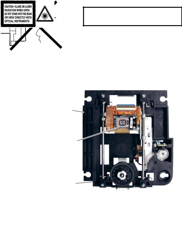
LASER BEAM SAFETY PRECAUTIONS
This DVD player uses a pickup that emits a laser beam.
Do not look directly at the laser beam coming from the pickup or allow it to strike against your skin.
The laser beam is emitted from the location shown in the figure. When checking the laser diode, be sure to keep your eyes at least 30 cm away from the pickup lens when the diode is turned on. Do not look directly at the laser beam.
CAUTION: Use of controls and adjustments, or doing procedures other than those specified herein, may result in hazardous radiation exposure.
Drive Mechanism Assembly
Laser Beam Radiation 
Laser Pickup
Turntable 
Location: Inside Top of DVD mechanism.
1-2-1 |
R3PLSP |
IMPORTANT SAFETY PRECAUTIONS
Product Safety Notice
Some electrical and mechanical parts have special safety-related characteristics which are often not evident from visual inspection, nor can the protection they give necessarily be obtained by replacing them with components rated for higher voltage, wattage, etc. Parts that have special safety characteristics are identified by a !on schematics and in parts lists. Use of a substitute replacement that does not have the same safety characteristics as the recommended replacement part might create shock, fire, and/or other hazards. The Product’s Safety is under review continuously and new instructions are issued whenever appropriate. Prior to shipment from the factory, our products are carefully inspected to confirm with the recognized product safety and electrical codes of the countries in which they are to be sold. However, in order to maintain such compliance, it is equally important to implement the following precautions when a set is being serviced.
Precautions during Servicing
A.Parts identified by the ! symbol are critical for safety. Replace only with part number specified.
B.In addition to safety, other parts and assemblies are specified for conformance with regulations applying to spurious radiation. These must also be replaced only with specified replacements.
Examples: RF converters, RF cables, noise blocking capacitors, and noise blocking filters, etc.
C.Use specified internal wiring. Note especially:
1)Wires covered with PVC tubing 2)Double insulated wires
3)High voltage leads
D.Use specified insulating materials for hazardous live parts. Note especially:
1)Insulation tape 2)PVC tubing 3)Spacers
4)Insulators for transistors
E.When replacing AC primary side components (transformers, power cord, etc.), wrap ends of wires securely about the terminals before soldering.
F.Observe that the wires do not contact heat producing parts (heatsinks, oxide metal film resistors, fusible resistors, etc.).
G.Check that replaced wires do not contact sharp edges or pointed parts.
H.When a power cord has been replaced, check that 5 - 6 kg of force in any direction will not loosen it.
I.Also check areas surrounding repaired locations.
J.Be careful that foreign objects (screws, solder droplets, etc.) do not remain inside the set.
K.Crimp type wire connector
The power transformer uses crimp type connectors which connect the power cord and the primary side of the transformer. When replacing the transformer, follow these steps carefully and precisely to prevent shock hazards.
Replacement procedure
1)Remove the old connector by cutting the wires at a point close to the connector.
Important: Do not re-use a connector. (Discard it.) 2)Strip about 15 mm of the insulation from the ends of the wires. If the wires are stranded, twist the
strands to avoid frayed conductors.
3)Align the lengths of the wires to be connected. Insert the wires fully into the connector.
4)Use a crimping tool to crimp the metal sleeve at its center. Be sure to crimp fully to the complete closure of the tool.
L.When connecting or disconnecting the internal connectors, first, disconnect the AC plug from the AC outlet.
1-3-1 |
DVD_SFNP |
Safety Check after Servicing
Examine the area surrounding the repaired location for damage or deterioration. Observe that screws, parts, and wires have been returned to their original positions. Afterwards, do the following tests and confirm the specified values to verify compliance with safety standards.
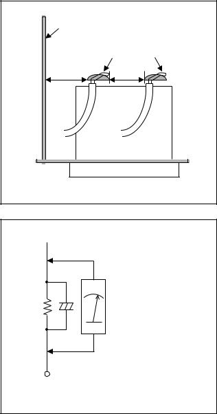
1. Clearance Distance
When replacing primary circuit components, confirm specified clearance distance (d) and (d’) between soldered terminals, and between terminals and surrounding metallic parts. (See Fig. 1)
Table 1 : Ratings for selected area
AC Line Voltage |
Clearance Distance (d), (d’) |
||
|
|
|
|
220 to 240 V |
≥ |
3 mm(d) |
|
≥ |
6 mm(d’) |
||
|
|||
|
|
|
|
Note: This table is unofficial and for reference only. Be sure to confirm the precise values.
2. Leakage Current Test
Confirm the specified (or lower) leakage current between B (earth ground, power cord plug prongs) and externally exposed accessible parts (RF terminals, antenna terminals, video and audio input and output terminals, microphone jacks, earphone jacks, etc.) is lower than or equal to the specified value in the table below.
Measuring Method (Power ON) :
Insert load Z between B (earth ground, power cord plug prongs) and exposed accessible parts. Use an AC voltmeter to measure across the terminals of load Z. See Fig. 2 and the following table.
Table 2: Leakage current ratings for selected areas
Chassis or Secondary Conductor |
|
|
Primary Circuit |
d' |
d |
Fig. 1
 Exposed Accessible Part
Z |
AC Voltmeter |
|
(High Impedance) |
||
|
BOne side of
Power Cord Plug Prongs
Fig. 2
AC Line Voltage |
Load Z |
Leakage Current (i) |
One side of power cord plug |
||
prongs (B) to: |
|||||
|
|
|
|
||
|
|
2kΩ RES. |
i≤ 0.7mA AC Peak |
RF or |
|
|
|
Connected in |
|||
|
|
i≤ 2mA DC |
Antenna terminals |
||
|
|
parallel |
|||
220 to 240 V |
|
|
|
||
|
|
|
|
||
|
50kΩ RES. |
i≤ 0.7mA AC Peak |
A/V Input, Output |
||
|
|
||||
|
|
Connected in |
|||
|
|
i≤ 2mA DC |
|||
|
|
parallel |
|
||
|
|
|
|
||
|
|
|
|
|
|
Note: This table is unofficial and for reference only. Be sure to confirm the precise values. |
|||||
1-3-2 |
DVD_SFNP |
STANDARD NOTES FOR SERVICING
NOTE: BOARD MEANS PRINTED CIRCUIT BOARD.
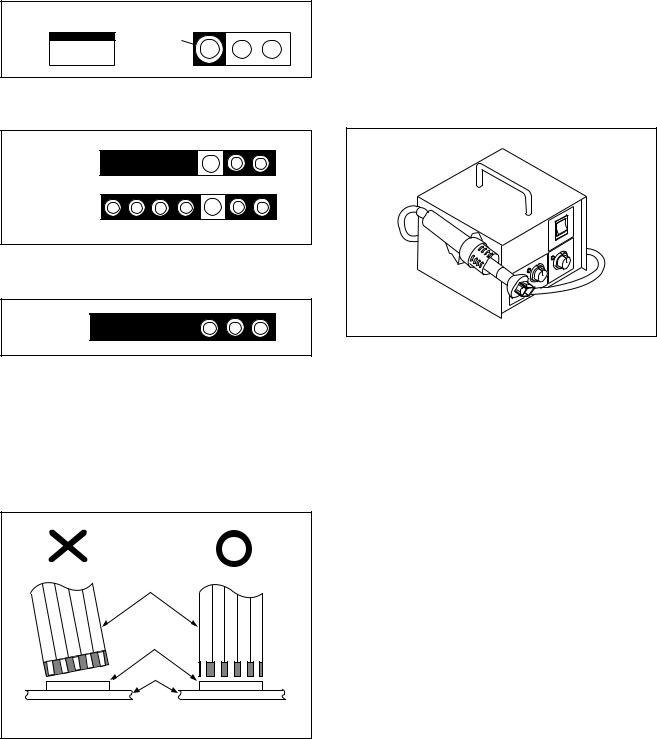
Circuit Board Indications
1.The output pin of the 3 pin Regulator ICs is indicated as shown.
Top View |
Bottom View |
Out |
Input |
In |
2.For other ICs, pin 1 and every fifth pin are indicated as shown.
5
Pin 1 


10
3.The 1st pin of every male connector is indicated as shown.
Pin 1 


Instructions for Connectors
1.When you connect or disconnect the FFC (Flexible Foil Connector) cable, be sure to first disconnect the AC cord.
2.FFC (Flexible Foil Connector) cable should be inserted parallel into the connector, not at an angle.
FFC Cable
Connector
BOARD
Pb (Lead) Free Solder
When soldering, be sure to use the Pb free solder.
How to Remove / Install Flat Pack-IC
1. Removal
With Hot-Air Flat Pack-IC Desoldering Machine:
1.Prepare the hot-air flat pack-IC desoldering machine, then apply hot air to the Flat Pack-IC (about 5 to 6 seconds). (Fig. S-1-1)
Fig. S-1-1
2.Remove the flat pack-IC with tweezers while applying the hot air.
3.Bottom of the flat pack-IC is fixed with glue to the BOARD; when removing entire flat pack-IC, first apply soldering iron to center of the flat pack-IC and heat up. Then remove (glue will be melted). (Fig. S-1-6)
4.Release the flat pack-IC from the BOARD using tweezers. (Fig. S-1-6)
CAUTION:
1.The Flat Pack-IC shape may differ by models. Use an appropriate hot-air flat pack-IC desoldering machine, whose shape matches that of the Flat Pack-IC.
2.Do not supply hot air to the chip parts around the flat pack-IC for over 6 seconds because damage to the chip parts may occur. Put masking tape around the flat pack-IC to protect other parts from damage. (Fig. S-1-2)
* Be careful to avoid a short circuit.
1-4-1 |
DVDN_SN |
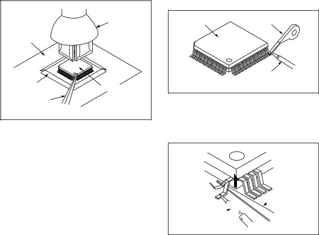
3.The flat pack-IC on the BOARD is affixed with glue, so be careful not to break or damage the foil of each pin or the solder lands under the IC when removing it.
|
Hot-air |
|
Flat Pack-IC |
|
Desoldering |
BOARD |
Machine |
|
|
Masking |
Flat Pack-IC |
Tape |
|
Tweezers |
|
|
Fig. S-1-2 |
With Soldering Iron:
1.Using desoldering braid, remove the solder from all pins of the flat pack-IC. When you use solder flux which is applied to all pins of the flat pack-IC, you can remove it easily. (Fig. S-1-3)
Flat Pack-IC |
Desoldering Braid |
|
Soldering Iron
Fig. S-1-3
2.Lift each lead of the flat pack-IC upward one by one, using a sharp pin or wire to which solder will not adhere (iron wire). When heating the pins, use a fine tip soldering iron or a hot air desoldering machine. (Fig. S-1-4)
Sharp
 Pin
Pin
Fine Tip 


Soldering Iron
Fig. S-1-4
3.Bottom of the flat pack-IC is fixed with glue to the BOARD; when removing entire flat pack-IC, first apply soldering iron to center of the flat pack-IC and heat up. Then remove (glue will be melted). (Fig. S-1-6)
4.Release the flat pack-IC from the BOARD using tweezers. (Fig. S-1-6)
1-4-2 |
DVDN_SN |
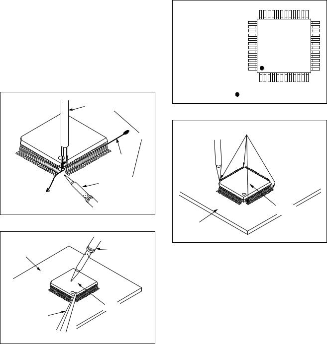
With Iron Wire:
1.Using desoldering braid, remove the solder from all pins of the flat pack-IC. When you use solder flux which is applied to all pins of the flat pack-IC, you can remove it easily. (Fig. S-1-3)
2.Affix the wire to a workbench or solid mounting point, as shown in Fig. S-1-5.
3.While heating the pins using a fine tip soldering iron or hot air blower, pull up the wire as the solder melts so as to lift the IC leads from the BOARD contact pads as shown in Fig. S-1-5.
4.Bottom of the flat pack-IC is fixed with glue to the BOARD; when removing entire flat pack-IC, first apply soldering iron to center of the flat pack-IC and heat up. Then remove (glue will be melted). (Fig. S-1-6)
5.Release the flat pack-IC from the BOARD using tweezers. (Fig. S-1-6)
Note: When using a soldering iron, care must be taken to ensure that the flat pack-IC is not being held by glue. When the flat pack-IC is removed from the BOARD, handle it gently because it may be damaged if force is applied.
Hot Air Blower |
or |
Iron Wire |
Soldering Iron |
To Solid |
Mounting Point |
Fig. S-1-5 |
BOARD |
Fine Tip |
Soldering Iron |
|
|
Flat Pack-IC |
Tweezers |
|
|
Fig. S-1-6 |
2. Installation
1.Using desoldering braid, remove the solder from the foil of each pin of the flat pack-IC on the BOARD so you can install a replacement flat packIC more easily.
2.The “●” mark on the flat pack-IC indicates pin 1. (See Fig. S-1-7.) Be sure this mark matches the 1 on the BOARD when positioning for installation. Then presolder the four corners of the flat pack-IC. (See Fig. S-1-8.)
3.Solder all pins of the flat pack-IC. Be sure that none of the pins have solder bridges.
Example :
Pin 1 of the Flat Pack-IC |
|
is indicated by a " " mark. |
Fig. S-1-7 |
|
Presolder |
Flat Pack-IC |
BOARD |
Fig. S-1-8 |
1-4-3 |
DVDN_SN |
Instructions for Handling Semiconductors
Electrostatic breakdown of the semi-conductors may occur due to a potential difference caused by electrostatic charge during unpacking or repair work.
1. Ground for Human Body
Be sure to wear a grounding band (1 MΩ ) that is properly grounded to remove any static electricity that may be charged on the body.
2. Ground for Workbench
Be sure to place a conductive sheet or copper plate with proper grounding (1 MΩ ) on the workbench or other surface, where the semi-conductors are to be placed. Because the static electricity charge on clothing will not escape through the body grounding band, be careful to avoid contacting semi-conductors with your clothing.
<Incorrect> |
|
|
BOARD |
<Correct> |
Grounding Band |
|
1MΩ |
|
BOARD |
1MΩ |
|
Conductive Sheet or
Copper Plate
1-4-4 |
DVDN_SN |
CABINET DISASSEMBLY INSTRUCTIONS
NOTE: BOARD MEANS PRINTED CIRCUIT BOARD.
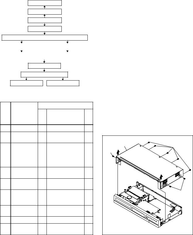
1. Disassembly Flowchart
This flowchart indicates the disassembly steps to gain access to item(s) to be serviced. When reassembling, follow the steps in reverse order. Bend, route, and dress the cables as they were originally.
[9]FAN
[8]FAN COVER
[1]COVER TOP
[2]PANEL FRONT
[3]DVD MECHANISM & DVD MAIN BOARD ASSEMBLY
[4] BOARD SWITCH |
|
[6] BOARD POWER SUPPLY |
||
|
|
|
|
|
|
|
|
|
|
ID/ |
|
|
Removal |
|
|
|
|
|
|
Loc. |
Part |
Fig. |
Remove/*Unhook/ |
|
No. |
|
Unlock/Release/ |
Note |
|
|
No. |
|||
|
|
Unplug/Desolder |
|
|
|
|
|
|
|
|
|
|
|
|
[10] |
PANEL REAR |
D5 |
(S-8), 6(S-9), |
--- |
2(S-10) |
||||
|
|
|
|
|
[11] |
BOARD |
D6 |
3(S-11) |
--- |
POWER |
||||
|
|
|
|
|
[12] |
BOARD JACK |
D6 |
Desolder |
--- |
|
|
|
|
|
[13] |
BOARD AFV |
D6 |
Desolder |
--- |
|
|
|
|
|
↓ |
↓ |
↓ |
↓ |
↓ |
(1) |
(2) |
(3) |
(4) |
(5) |
Note:
(1) Identification (location) No. of parts in the figures
[5] BOARD HOLDER |
|
[7] POWER HOLDER |
(2) Name of the part |
||
|
|
|
|
|
|
|
|
|
|
|
|
|
[10] PANEL REAR |
|
(3) Figure Number for reference |
|
|||
|
|
(4) Identification of parts to be removed, unhooked, |
|||||
|
|
|
|
|
|||
|
[11] BOARD POWER |
|
|
unlocked, released, unplugged, unclamped, or |
|||
|
|
|
desoldered. |
|
|||
|
|
|
|
|
|
|
|
|
[12] BOARD JACK |
[13] BOARD AFV |
|
|
P = Spring, L = Locking Tab, S = Screw, |
||
|
|
|
|
|
|
CN = Connector |
|
2. Disassembly Method |
|
|
* = Unhook, Unlock, Release, Unplug, or Desolder |
||||
|
|
e.g. 2(S-2) = two Screws (S-2), |
|
||||
|
|
|
Removal |
|
|
2(L-2) = two Locking Tabs (L-2) |
|
ID/ |
|
|
|
(5) Refer to “Reference Notes.” |
|
||
|
|
Remove/*Unhook/ |
|
|
|
|
|
Loc. |
Part |
Fig. |
Note |
Reference Notes |
|
||
No. |
|
No. |
Unlock/Release/ |
|
|
|
|
|
|
Unplug/Desolder |
|
1. CAUTION 1: Locking Tabs (L-1) and (L-2) are |
|||
[1] |
COVER TOP |
D1 |
8(S-1) |
--- |
|
fragile. Be careful not to break them. |
|
|
|
|
|||||
[2] |
PANEL |
D2 |
*6(L-1), *3(L-2) |
1 |
|
|
|
FRONT |
|
[1] COVER TOP |
|
||||
|
DVD |
|
|
|
|
(S-1) |
|
|
|
|
|
|
|
||
|
MECHANISM |
|
4(S-2), *CN101, |
|
|
(S-1) |
|
[3] |
& DVD MAIN |
D3 |
*CN701, LOCKING |
--- |
|
|
|
|
BOARD |
|
CARD SPACERS |
|
|
|
|
|
ASSEMBLY |
|
|
|
|
|
|
[4] |
BOARD |
D4 |
(S-3), Desolder |
--- |
|
|
|
SWITCH |
|
|
|
||||
[5] |
BOARD |
D4 |
2(S-4) |
--- |
|
|
|
HOLDER |
|
|
|
||||
|
BOARD |
|
|
|
|
|
(S-1) |
[6] |
POWER |
D4 |
2(S-5), *CN1152 |
--- |
|
|
|
|
SUPPLY |
|
|
|
|
|
|
[7] |
POWER |
D4 |
(S-6) |
--- |
|
|
|
HOLDER |
|
|
|
||||
[8] |
FAN COVER |
D5 |
2(S-7) |
--- |
|
|
|
[9] |
FAN |
D5 |
FAN EARTH, |
--- |
|
|
|
*CN1601 |
|
|
Fig. D1 |
||||
|
|
|
|
|
1-5-1 |
|
E7B71DC |

[2] PANEL |
|
FRONT |
|
(L-1) |
|
|
(L-1) |
|
(L-1) |
(L-2) |
Fig. D2 |
|
|
(S-2) |
(S-2) |
[3] DVD MECHANISM & DVD MAIN BOARD ASSEMBLY
CN101
CN701
LOCKING
CARD
SPACER
LOCKING
CARD
SPACER
Fig. D3
(S-5) |
[6] BOARD POWER SUPPLY |
|
|
[4] BOARD SWITCH |
(S-4) |
(S-6) |
Desolder |
|
|
|
|
|
(S-3) |
|
|
CN1152 |
[5] BOARD |
|
|
HOLDER |
[7] POWER |
|
|
HOLDER |
|
|
|
|
Fig. D4 |
[8] FAN COVER |
(S-7) |
FAN EARTH |
|
[9] FAN |
|
[10] PANEL REAR |
|
|
(S-9) |
|
(S-10) |
|
(S-8) |
CN1601 |
|
|
Fig. D5 |
[13] BOARD AFV
(S-11) |
[12] BOARD JACK |
|
|
|
(S-11) |
Desolder
[11] BOARD
POWER Desolder
Fig. D6
1-5-2 |
E7B71DC |
 Loading...