


DR-150-SB

FILE NO. 810-200576
SERVICE MANUAL
DVD VIDEO RECORDER
D-R150-SB
DIGITAL VIDEO
1
2
3
4
5
6
+
10
7
89
0
CLEAR
DVD TV
ENTER
OPEN/CLOSE
TIME SLIP
TV VOL
CH
T.SEARCH
PROGRESSIVE
INPUT SEL.
TOP MENU
MENU
STOP
PAU
S
E
PLAY
SKIP FWDSKIP REV
ADJUST
QUICK
DISPLAY
SUBTITLE
REC
REC MODE
ZOOM ANGLE
TV/DVR
AUDIO
INSTANT
REPLAY
INSTANT
SKIP
E
A
S
Y
NAV
I
ON/STANDBY
DIVIDE
CHP
SEP. 2005 S

CONTENTS
1. Precautions
2. Product Specification
3. Software Update
4. Disassembly and Reassembly
5. Troubleshooting
6. Exploded View and Parts List
7. Electrical Parts List
8. Block Diagrams
9. Wiring Diagram
10. PCB Diagrams
11. Schematic Diagrams
12. Operating Instructions
13. Circuit Operating Descriptions
14. Reference Information
1. Precautions
1-1 Safety Precautions
1-1
1) Before returning an instrument to the customer,
always make a safety check of the entire instrument,
including, but not limited to, the following items:
(1) Be sure that no built-in protective devices are
defective or have been defeated during servicing.
(1)Protective shields are provided to protect both
the technician and the customer. Correctly replace
all missing protective shields, including any
removed for servicing convenience.
(2)When reinstalling the chassis and/or other as-
sembly in the cabinet, be sure to put back in place
all protective devices, including, but not limited to,
nonmetallic control knobs, insulating fish papers,
adjustment and compartment covers/shields, and
isolation resistor/capacitor networks. Do not oper-
ate this instrument or permit it to be operated with-
out all protective devices correctly installed and
functioning.
(2) Be sure that there are no cabinet openings through
which adults or children might be able to insert
their fingers and contact a hazardous voltage. Such
openings include, but are not limited to, excessive-
ly wide cabinet ventilation slots, and an improper-
ly fitted and/or incorrectly secured cabinet back
cover.
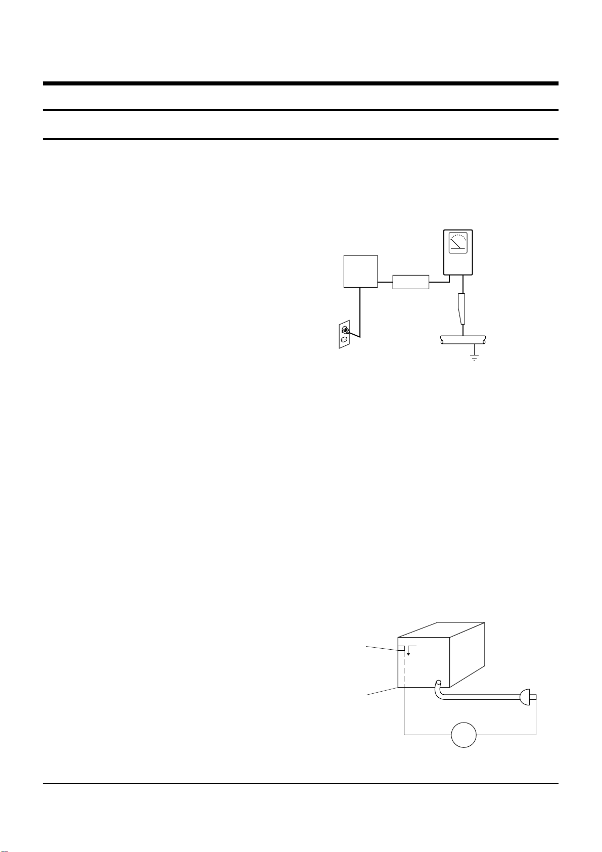
(3) Leakage Current Hot Check-With the instrument
completely reassembled, plug the AC line cord
directly into a 230V(220V ~ 240V) AC outlet. (Do
not use an isolation transformer during this test.)
Use a leakage current tester or a metering system
that complies with American National Standards
institute (ANSI) C101.1 Leakage Current for
Appliances and Underwriters Laboratories (UL)
1270 (40.7). With the instrument’s AC switch first in
the ON position and then in the OFF position, mea-
sure from a known earth ground (metal water pipe,
conduit, etc.) to all exposed metal parts of the
instrument (antennas, handle brackets, metal cabi-
nets, screwheads, metallic overlays, control shafts,
etc.), especially any exposed metal parts that offer
an electrical return path to the chassis.
Any current measured must not exceed 0.5mA.
Reverse the instrument power cord plug in the out-
let and repeat the test. See Fig. 1-1.
Any measurements not within the limits specified
herein indicate a potential shock hazard that must
be eliminated before returning the instrument to
the customer.
Fig. 1-1 AC Leakage Test
(4) Insulation Resistance Test Cold Check-(1) Unplug
the power supply cord and connect a jumper wire
between the two prongs of the plug. (2) Turn on the
power switch of the instrument. (3) Measure the
resistance with an ohmmeter between the
jumpered AC plug and all exposed metallic cabinet
parts on the instrument, such as screwheads,
antenna, control shafts, handle brackets, etc. When
an exposed metallic part has a return path to the
chassis, the reading should be between 1 and 5.2
megohm. When there is no return path to the chas-
sis, the reading must be infinite. If the reading is
not within the limits specified, there is the possibil-
ity of a shock hazard, and the instrument must be
repaired and rechecked before it is returned to the
customer. See Fig. 1-2.
Fig. 1-2 Insulation Resistance Test
DEVICE
UNDER
TEST
(READING SHOULD
NOT BE ABOVE
0.5mA)
LEAKAGE
CURRENT
TESTER
EARTH
GROUND
TEST ALL
EXPOSED METER
SURFACES
ALSO TEST WITH
PLUG REVERSED
(USING AC ADAPTER
PLUG AS REQUIRED)
2-WIRE CORD
Antenna
Terminal
Exposed
Metal Part
ohm
ohmmeter

Precautions
1-2
2) Read and comply with all caution and safety re-
lated notes on or inside the cabinet, or on the chas-
sis.
3) Design Alteration Warning-Do not alter or add to
the mechanical or electrical design of this instru-
ment. Design alterations and additions, including
but not limited to, circuit modifications and the
addition of items such as auxiliary audio output
connections, might alter the safety characteristics of
this instrument and create a hazard to the user. Any
design alterations or additions will make you, the
servicer, responsible for personal injury or property
damage resulting therefrom.
4) Observe original lead dress. Take extra care to
assure correct lead dress in the following areas:
(1) near sharp edges, (2) near thermally hot parts (be
sure that leads and components do not touch ther-
mally hot parts), (3) the AC supply, (4) high voltage,
and (5) antenna wiring. Always inspect in all areas
for pinched, out-of-place, or frayed wiring, Do not
change spacing between a component and the
printed-circuit board. Check the AC power cord for
damage.
5) Components, parts, and/or wiring that appear to
have overheated or that are otherwise damaged
should be replaced with components, parts and/ or
wiring that meet original specifications.
Additionally, determine the cause of overheating
and/or damage and, if necessary, take corrective
action to remove any potential safety hazard.
6) Product Safety Notice-Some electrical and mechani-
cal parts have special safety-related characteristics
which are often not evident from visual inspection,
nor can the protection they give necessarily be
obtained by replacing them with components rated
for higher voltage, wattage, etc. Parts that have spe-
cial safety characteristics are identified by shading,
an ( )or a ( )on schematics and parts lists. Use
of a substitute replacement that does not have the
same safety characteristics as the recommended
replacement part might create shock, fire and/or
other hazards. Product safety is under review con-
tinuously and new instructions are issued whenev-
er appropriate.

Precautions
1-3
CAUTION : Before servicing units covered by this
service manual and its supplements, read and follow
the Safety Precautions section of this manual.
Note : If unforseen circumstances create conflict
between the following servicing precautions and any
of the safety precautions, always follow the safety pre-
cautions. Remember: Safety First.
1-2-1 General Servicing Precautions
(1) a. Always unplug the instrument’s AC power cord
from the AC power source before (1) re-moving
or reinstalling any component, circuit board,
module or any other instrument assembly, (2)
disconnecting any instrument electrical plug or
other electrical connection, (3) connecting a test
substitute in parallel with an electrolytic capaci-
tor in the instrument.
b. Do not defeat any plug/socket B+ voltage inter-
locks with which instruments covered by this
service manual might be equipped.
c. Do not apply AC power to this instrument and
/or any of its electrical assemblies unless all
solid-state device heat sinks are correctly in-
stalled.
d. Always connect a test instrument’s ground lead
to the instrument chassis ground before connect-
ing the test instrument positive lead. Always
remove the test instrument ground lead last.
Note : Refer to the Safety Precautions section ground
lead last.
(2) The service precautions are indicated or printed on
the cabinet, chassis or components. When servic-
ing, follow the printed or indicated service precau-
tions and service materials.
(3) The components used in the unit have a specified
flame resistance and dielectric strength.
When replacing components, use components
which have the same ratings. Components identi-
fied by shading, by( ) or by ( ) in the circuit dia-
gram are important for safety or for the characteris-
tics of the unit. Always replace them with the exact
replacement components.
(4) An insulation tube or tape is sometimes used and
some components are raised above the printed
wiring board for safety. The internal wiring is
sometimes clamped to prevent contact with heat-
ing components. Install such elements as they
were.
(5) After servicing, always check that the removed
screws, components, and wiring have been in-
stalled correctly and that the portion around the
serviced part has not been damaged and so on.
Further, check the insulation between the blades of
the attachment plug and accessible conductive
parts.
1-2-2 Insulation Checking Procedure
Disconnect the attachment plug from the AC outlet
and turn the power ON. Connect the insulation resi-
stance meter (500V) to the blades of the attachment
plug. The insulation resistance between each blade of
the attachment plug and accessible conductive
parts(see note) should be more than 1 Megohm.
Note : Accessible conductive parts include metal pan-
els, input terminals, earphone jacks, etc.
1-2 Servicing Precautions

Precautions
1-4
Electrostatically Sensitive Devices (ESD)
Some semiconductor (solid state) devices can be dam-
aged easily by static electricity.
Such components commonly are called Electrostati-
cally Sensitive Devices(ESD). Examples of typical ESD
devices are integrated circuits and some field-effect
transistors and semiconductor chip components. The
following techniques should be used to help reduce
the incidence of component damage caused by static
electricity.
(1) Immediately before handling any semiconductor
component or semiconductor-equipped assembly,
drain off any electrostatic charge on your body by
touching a known earth ground. Alternatively,
obtain and wear a commercially available dis-
charging wrist strap device, which should be
removed for potential shock reasons prior to apply-
ing power to the unit under test.
(2) After removing an electrical assembly equipped
with ESD devices, place the assembly on a conduc-
tive surface such as aluminum foil, to prevent elec-
trostatic charge buildup or exposure of the assem-
bly.
(3) Use only a grounded-tip soldering iron to solder or
unsolder ESD devices.
(4) Use only an anti-static solder removal devices.
Some solder removal devices not classified as
“anti-static” can generate electrical charges suffi-
cient to damage ESD devices.
(5) Do not use freon-propelled chemicals. These can
generate electrical charges sufficient to damage
ESD devices.
(6) Do not remove a replacement ESD device from its
protective package until immediately before your
are ready to install it.(Most replacement ESD
devices are packaged with leads electrically short-
ed together by conductive foam, aluminum foil or
comparable conductive materials).
(7) Immediately before removing the protective ma-
terials from the leads of a replacement ESD device,
touch the protective material to the chassis or cir-
cuit assembly into which the device will be
installed.
CAUTION : Be sure no power is applied to the ch-
assis or circuit, and observe all other safety precau-
tions.
(8) Minimize bodily motions when handling unpack-
aged replacement ESD devices. (Otherwise harm-
less motion such as the brushing together of your
clothes fabric or the lifting of your foot from a car-
peted floor can generate static electricity sufficient
to damage an ESD device).
1-3 ESD Precautions
Power requirement during operation 25W
Power requirement at standby 3.1W
Power supply 230V AC, 50 Hz
Mass 3.5kg
External dimension Width 430 x Height 69 x Depth 316mm
System: Frequency synthesizer
Channel coverage: PAL I VHF: A-J, 11, 13, E2-E12
Tuner UHF: E21-E69
CATV: X, Y, Z, S1-S41, 1-53
(48MHz to 464MHz, 8MHz steps)
Serial input/output terminal VHF/UHF: 75Ω, IEC Connector
Signal system Standard PAL Colour TV system
Laser Semiconductor laser, Wavelength: 650nm/780nm
Format
DVD-VR format
DVD-Video format
Image recording system MPEG2
Sound recording system Dolby Digital M1
1.0Vp-p (75Ω), Sync signal negative,
VIDEO input Pin jack x 1 system, 1 in front
SCART socket x 2 at rear
1.0Vp-p (75Ω), Sync signal negative,
VIDEO output Pin jack x 1 system, 1 at rear
SCART socket x 2 at rear
(Y) 1.0Vp-p (75Ω), Sync signal
S-VIDEO input
(C) 0.286Vp-p (75Ω)
Mini DIN4 Pin x 1 system
SCART socket x 1 at rear
(Y) 1.0Vp-p (75Ω), Sync signal
S-VIDEO output
(C) 0.286Vp-p (75Ω), 1 at rear
Mini DIN4 Pin x 1 system
SCART socket x 1 at rear
Y output (green), 1.0Vp-p (75Ω)
Component output (Y,P
B
, P
R
)
Sync signal negative, Pin jack
PB, PR output (blue, red), 0.7Vp-(75Ω),
Pin jack x 1 system each
(R) 0.7Vp-p (75Ω)
RGB output
(G) 0.7Vp-p (75Ω)
(B) 0.7Vp-p (75Ω)
SCART socket x 1 at rear (AV1
2.0V (rms), 50kΩ or below, pin
AUDIO input
(L, R) x 1 system
1 in front
SCART socket x 2 at rear
2.0V (rms), 200Ω or above, pin
AUDIO output
(L, R) x 1 system
2 at rear
SCART socket x 2 at rear
2-1
2. Product Specification
Product Specification
2-2
DIGITAL AUDIO OUT(COAXIAL terminal) 0.5Vp-p (75Ω), pin jack x 1 system
Remote control Wireless remote control (SE-R0208)
Operating conditions
Temperature: 5°C ~ 35°C,
Position: Horizontal
Clock display 24 hour digital display
Clock accuracy Quartz (monthly deviation: approximately ±30 seconds)
Remote control ....................................................... 1
Batteries (R6) .......................................................... 2
Coaxial cable .......................................................... 1
Supplied Accessories Video/Audio cable .................................................. 1
OWNER’S MANUAL (INSTALLATION GUIDE) ........ 1
OWNER’S MANUAL (OPERATIONS)........................ 1
Quick Reference ...................................................... 1
• This model complies with the specifications above.
• Designs and specifications are subject to change without notice.
• This model may not be compatible with features and/or specifications that may be added in the future.
• The screen illustrations used in this Operating Guide are for reference purposes only. Because the screen illustrations
used in this Operating Guide are simplified for easy recognition, they may vary slightly from the unit’s actual screen
displays.

Product Specification
2-4
MEMO
3-1
3. Software Update
3-1-1 Introduction
Toshiba will often support software update to improve the performance of DVD Recorder to the latest status.
3-1-2 How to make Main-Board(Back-end)
! Power on.
@ Disc tray open.
# Insert update CD.
$ Tray close. Set loads update-data in CD.
When update is starting normally, LED-display displays "V-UP".
% Wait until update is finished. After update is finished, LED-display displays "MP" for a moment.
And opening tray, set turns stand-by mode automatically.
It is very important : please read the below notice before updating your unit.
The following events may interrupt the update process and MAY RESULT IN PERMANENT DAMAGE TO THE
UNIT WHILE UPDATING
! The power cord unplugged.
@ Power Outage.
# Dirt or Scratches on the disc.
$ Opening a disc tray during processing.
Caution

3-2
Software Update
MEMO
4-1
4. Disassembly and Reassembly
4-1 Cabinet and PCB
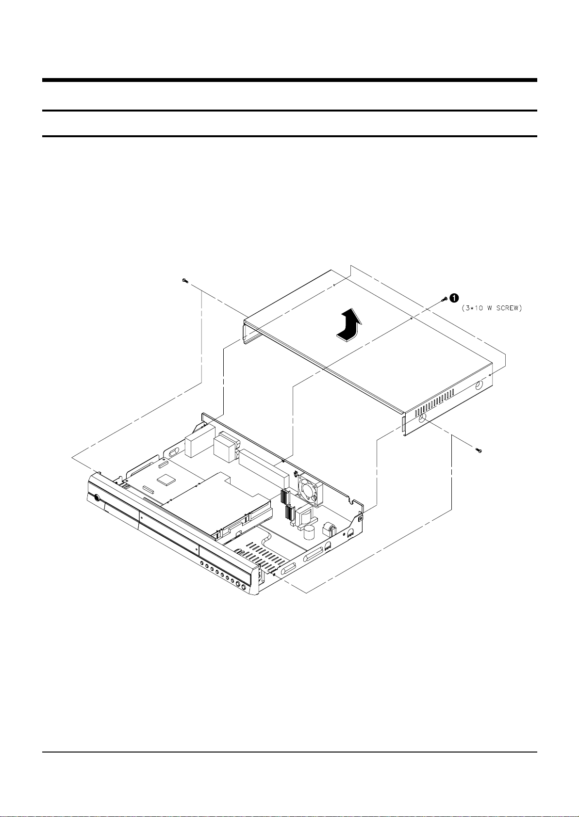
4-1-1 Top Cabinet Removal
1) Remove 5 Screws Œ.
2) Lift up the Top Cabinet in direction of arrow.
Fig. 4-1 Top Cabinet Removal
Note : Reassembly in reverse order.
5 SCREWS
4-2
Disassembly and Reaasembly
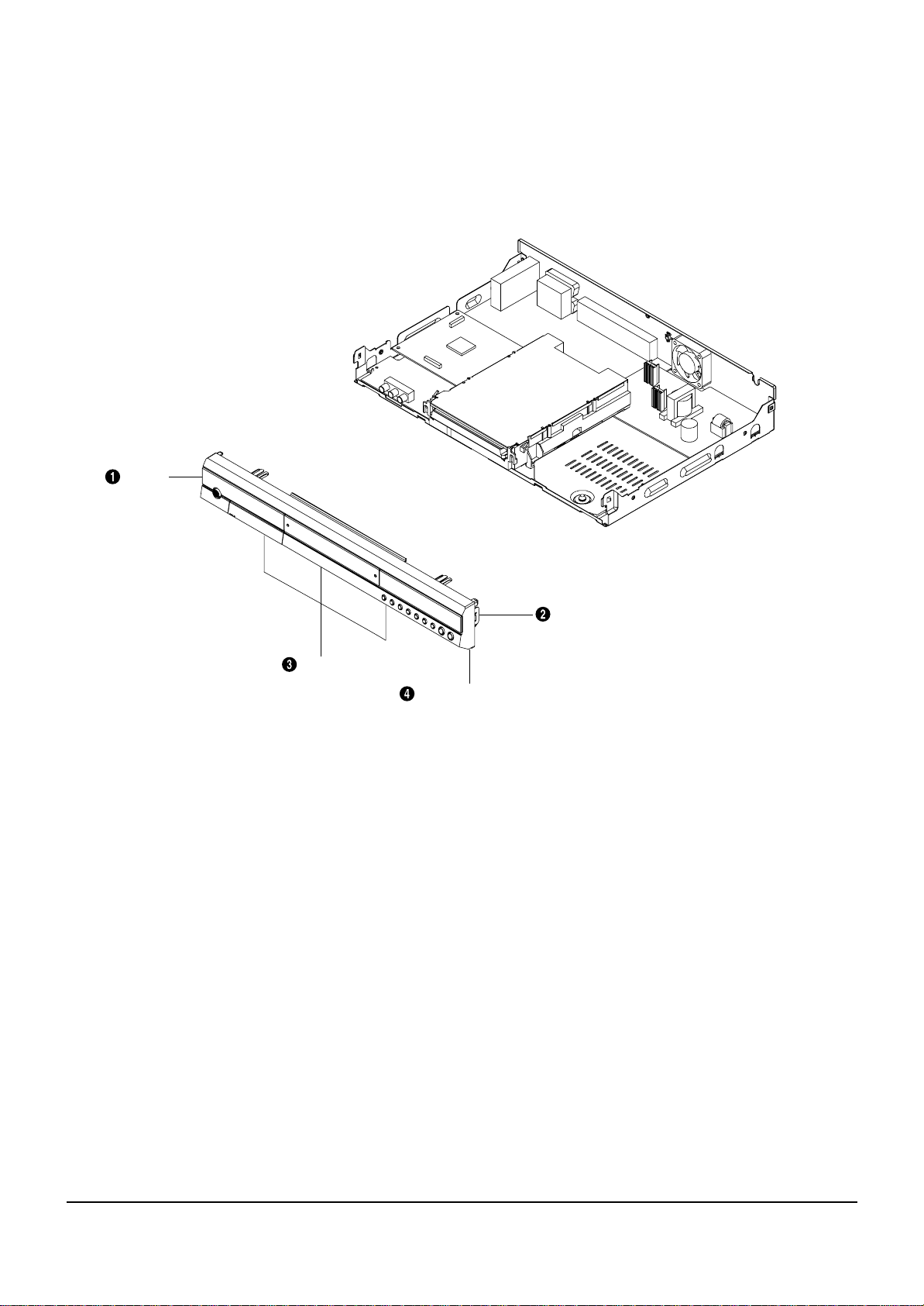
1 HOOK
3 HOOKS
1 HOOK
ASS'Y FRONT-CABINET
Fig. 4-2 Ass’y Front-Cabinet Removal
4-1-2 Ass’y Front-Cabinet Removal
1) Release 5 Hooks Œ, ´, ˇ and Ass’y Front-Cabinet ¨.
Disassembly and Reaasembly
4-3
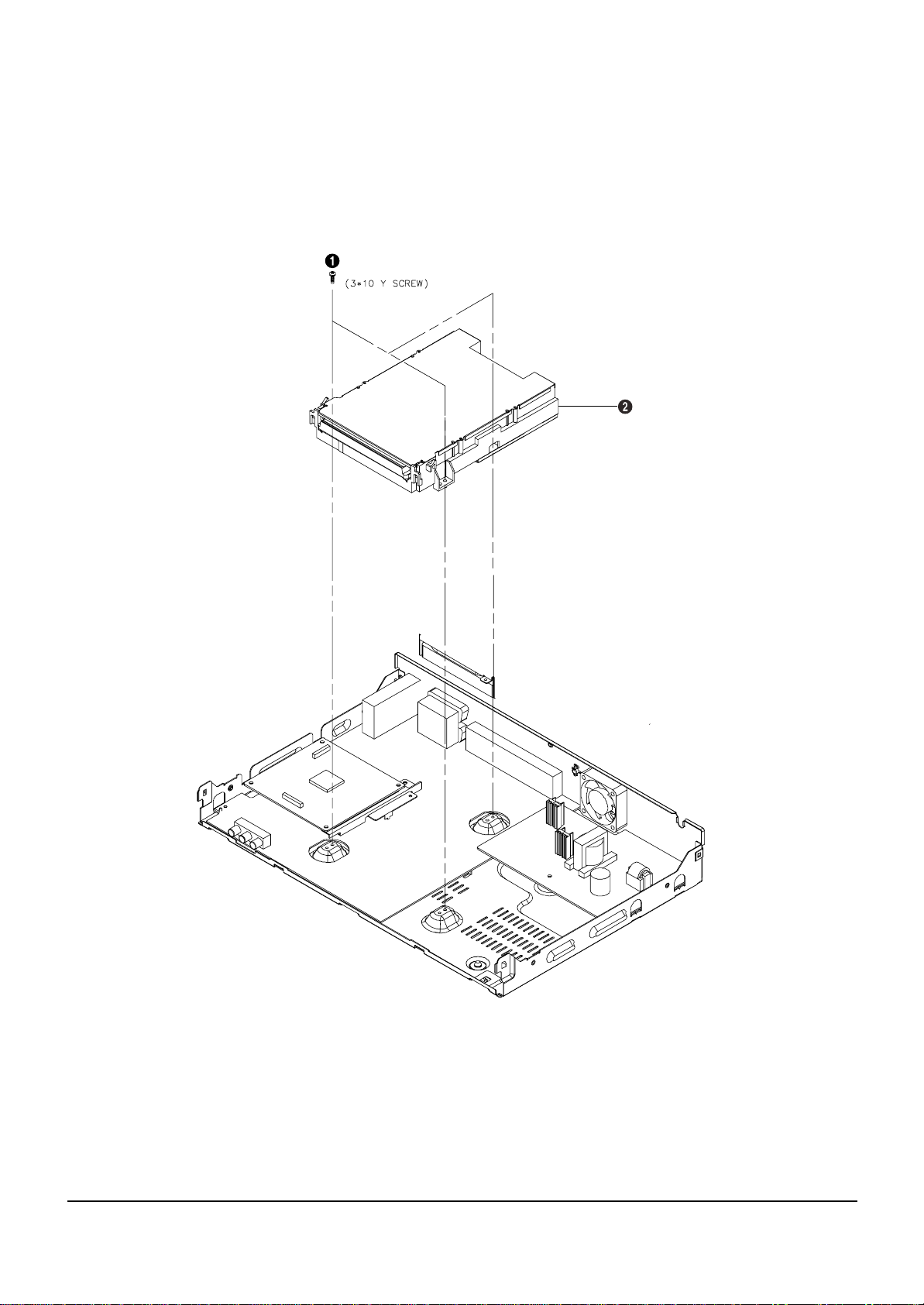
ASS'Y-LOADER
3 SCREWS
4-1-3 Ass’y LOADER Removal
1) Remove 3 Screws Œ, from the Ass’y LOADER ´ and lift it up.
Fig. 4-3 Ass’y LOADER Removal
4-4
Disassembly and Reaasembly
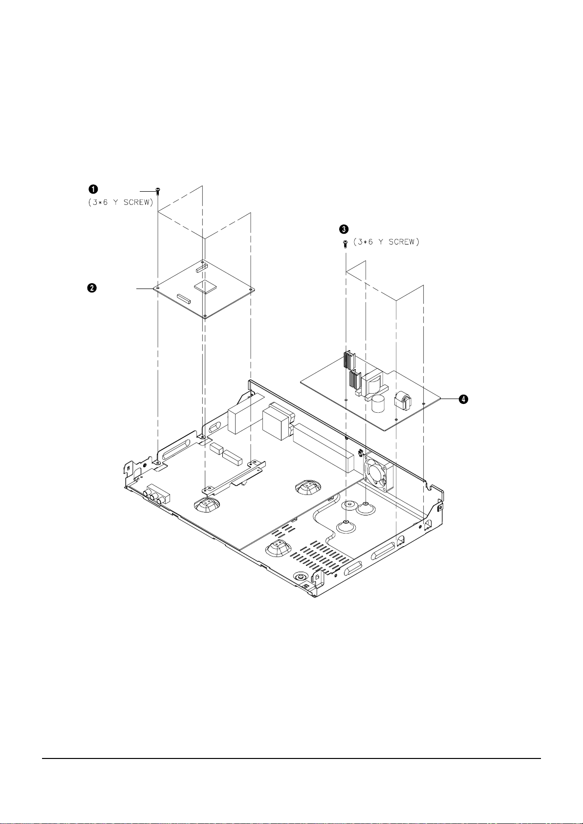
4 SCREWS
MAIN PCB
4 SCREWS
SMPS PCB
Fig. 4-4 Main PCB and S.M.P.S. PCB Removal
4-1-4 Main PCB and S.M.P.S. PCB Removal
1) Remove 4 Screws Œ, from the Main PCB ´ and lift it up.
2) Remove 4 Screws ˇ, from the S.M.P.S. PCB ¨ and lift it up.
Disassembly and Reaasembly
4-5
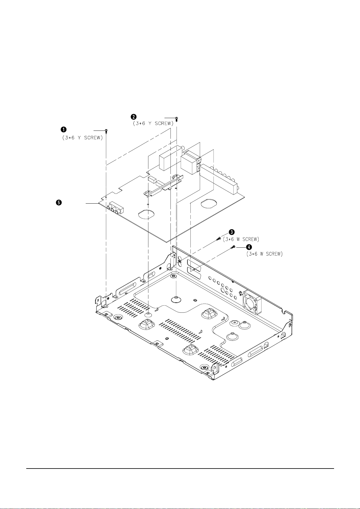
4-1-5 Jack PCB Removal
1) Remove 6 Screws Œ, ´, ˇ, ¨ from the Jack PCB ˆ and lift it up.
2 SCREWS
JACK PCB
1
SC
REW 1 SCREW
2 SCREWS
1 SCREW
Fig. 4-5 Jack PCB Removal
4-6
Disassembly and Reaasembly
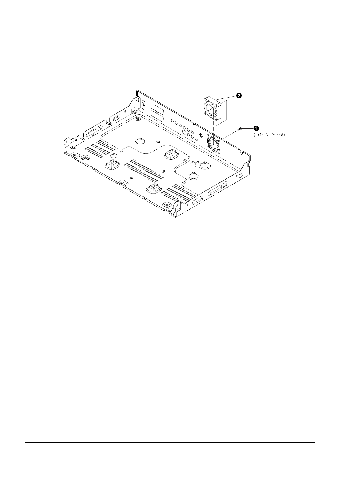
4-1-6 DC FAN Removal
1) Remove 2 Screws Œ, from the DC Fan ´ and lift it up.
DC FAN
2 SCREWS
Fig. 4-6 DC FAN Removal
Disassembly and Reaasembly
4-7
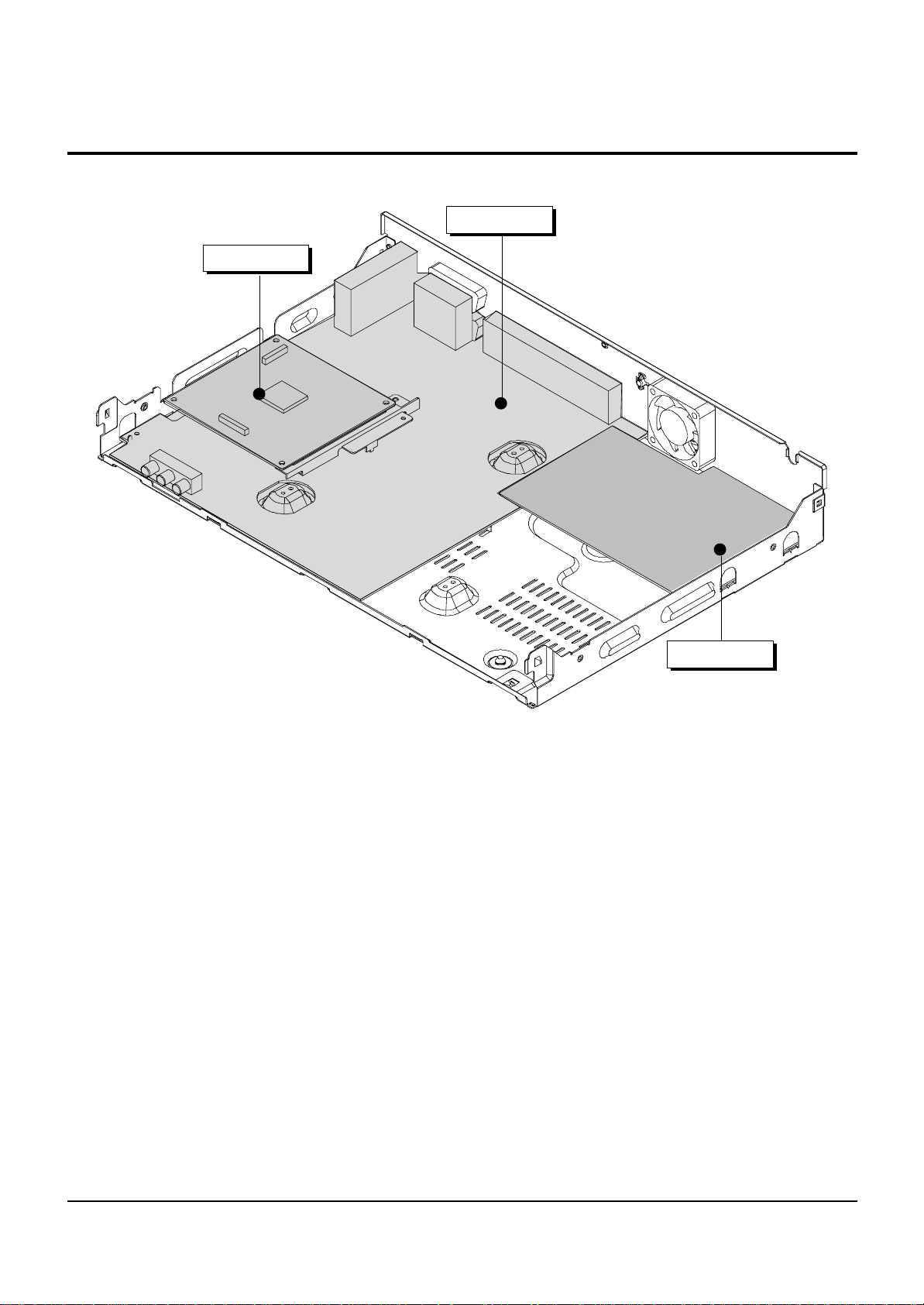
4-2 PCB Location
Fig. 4-7 PCB Location
S.M.P.S. PCB
JACK PCB
MAIN PCB

4-8
Disassembly and Reaasembly
MEMO
5-1
5. Troubleshooting
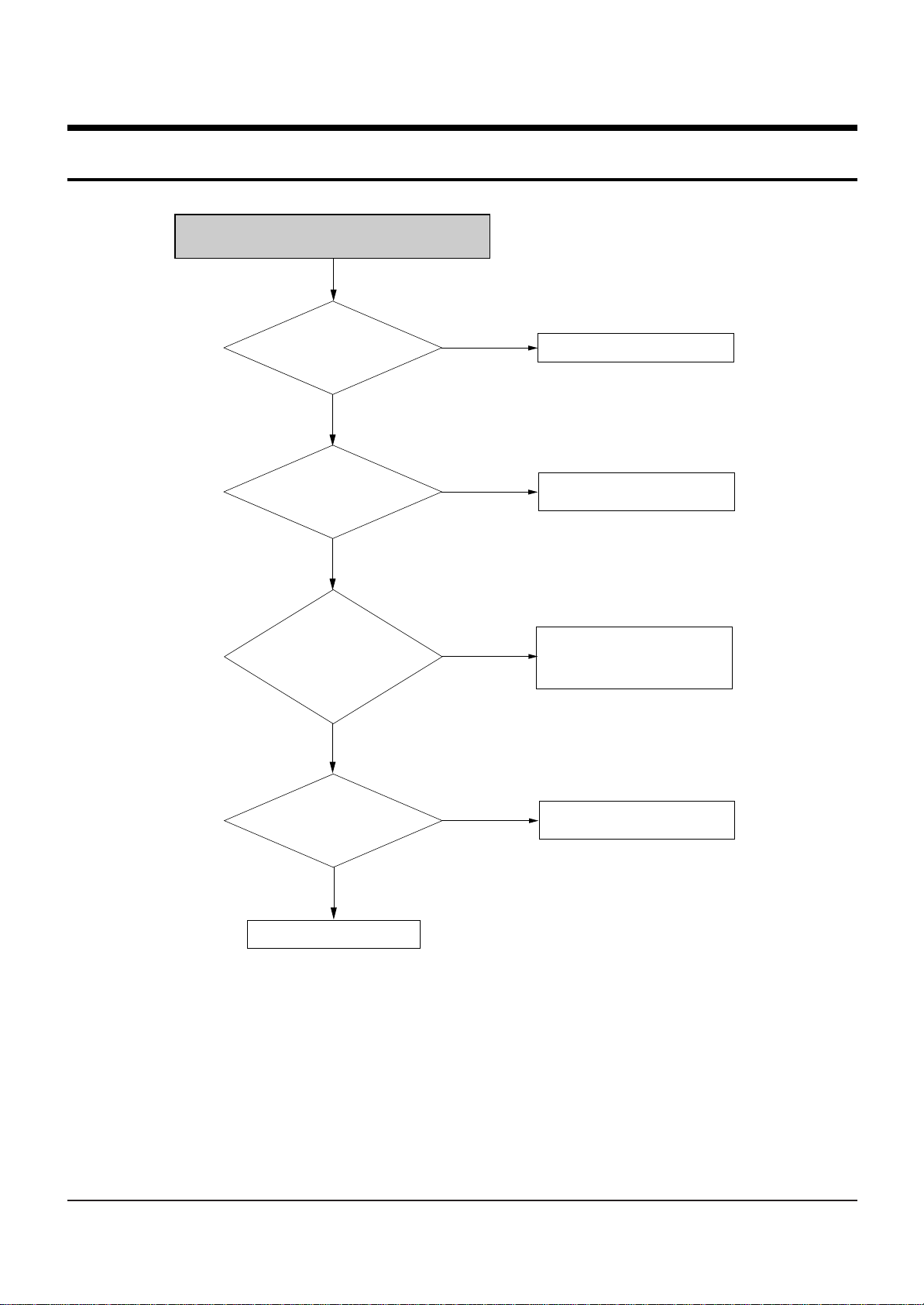
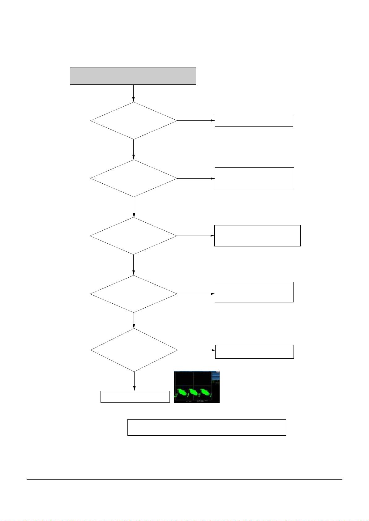
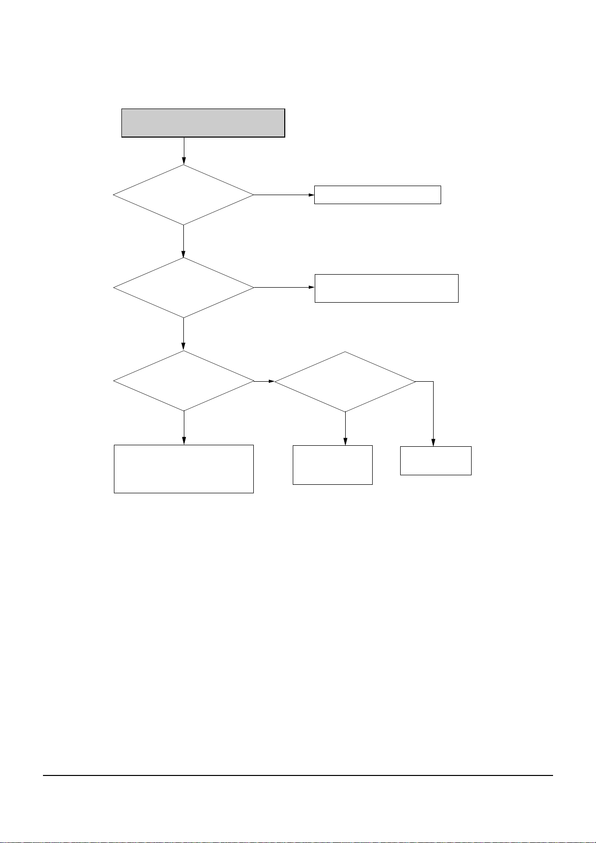
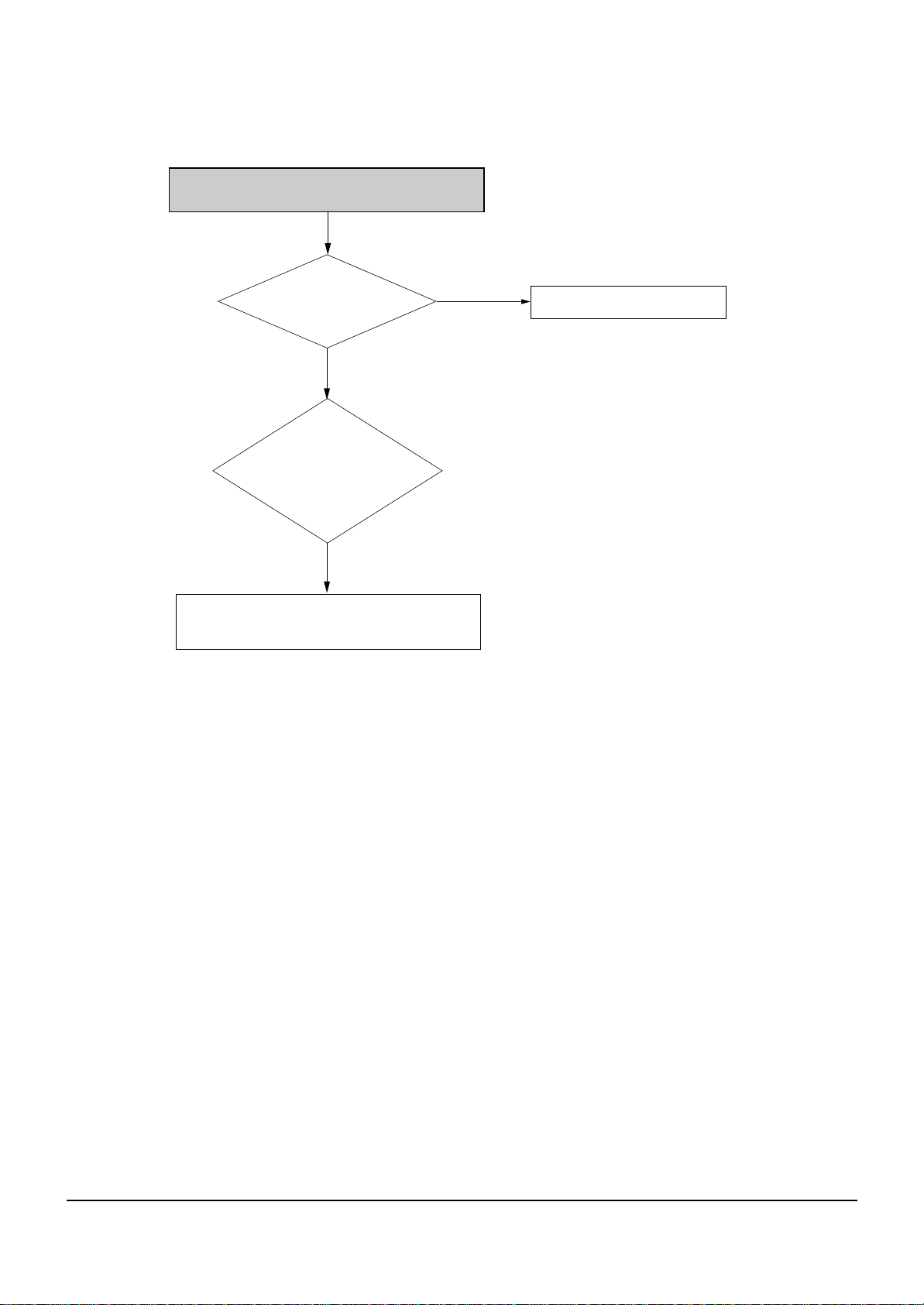
The signal at PCON2
pin 10 is high?
Change SMPS Board
Check fuse
No
No
Check soldering condition and
MIC01, MIC03 peripheral
componenents.
No
Check regulator ICs and if
IC is dead change IC
Yes
Yes
Yes
NO Power Detected
(Stand by LED OFF)
The connection between
Jack and key PCB is correct?
Check connection between
Jack and Key PCB
Yes
No
Soldering
condition of MIC01, MIC03 is OK?
(cold soldering or short)
Regulator ICs in SMPS are OK?
(Output voltage)
Troubleshooting
5-2
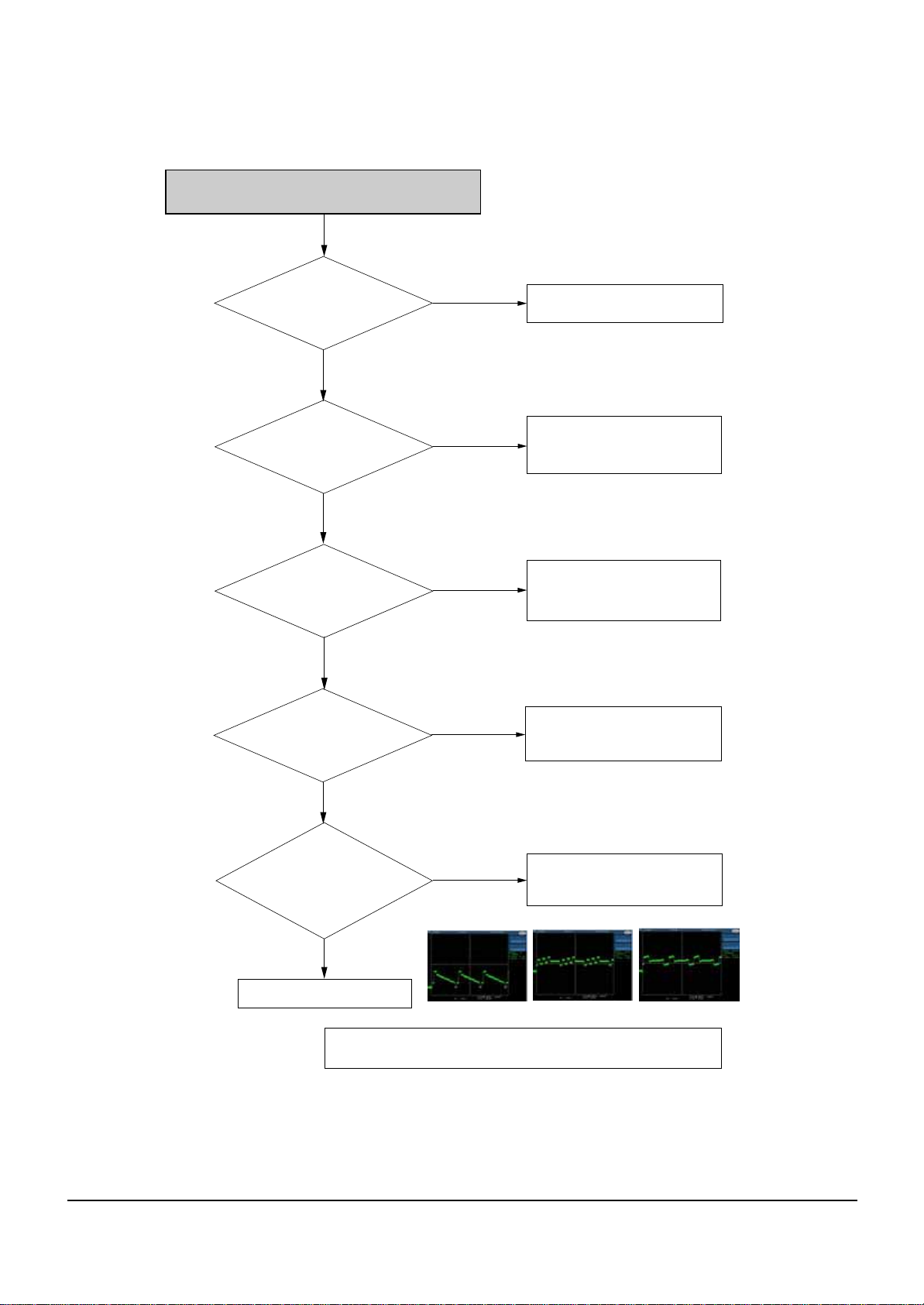
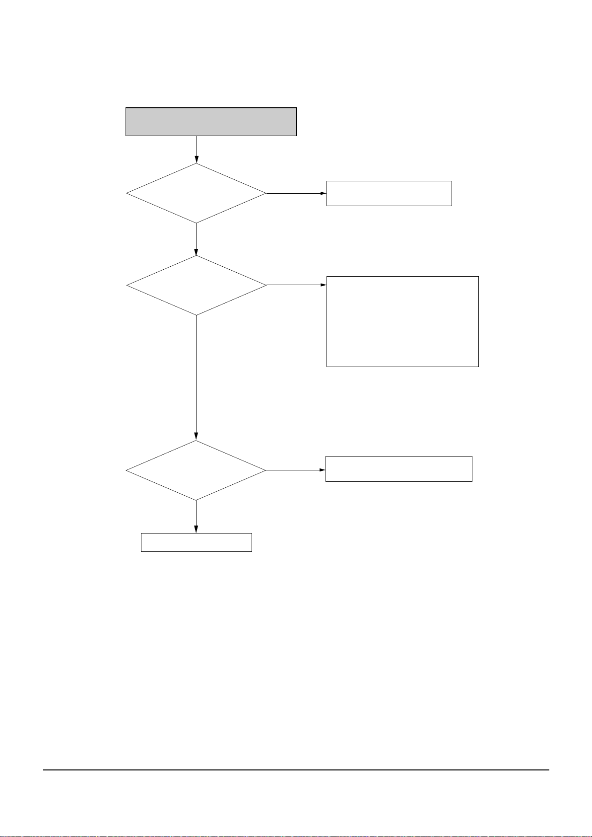
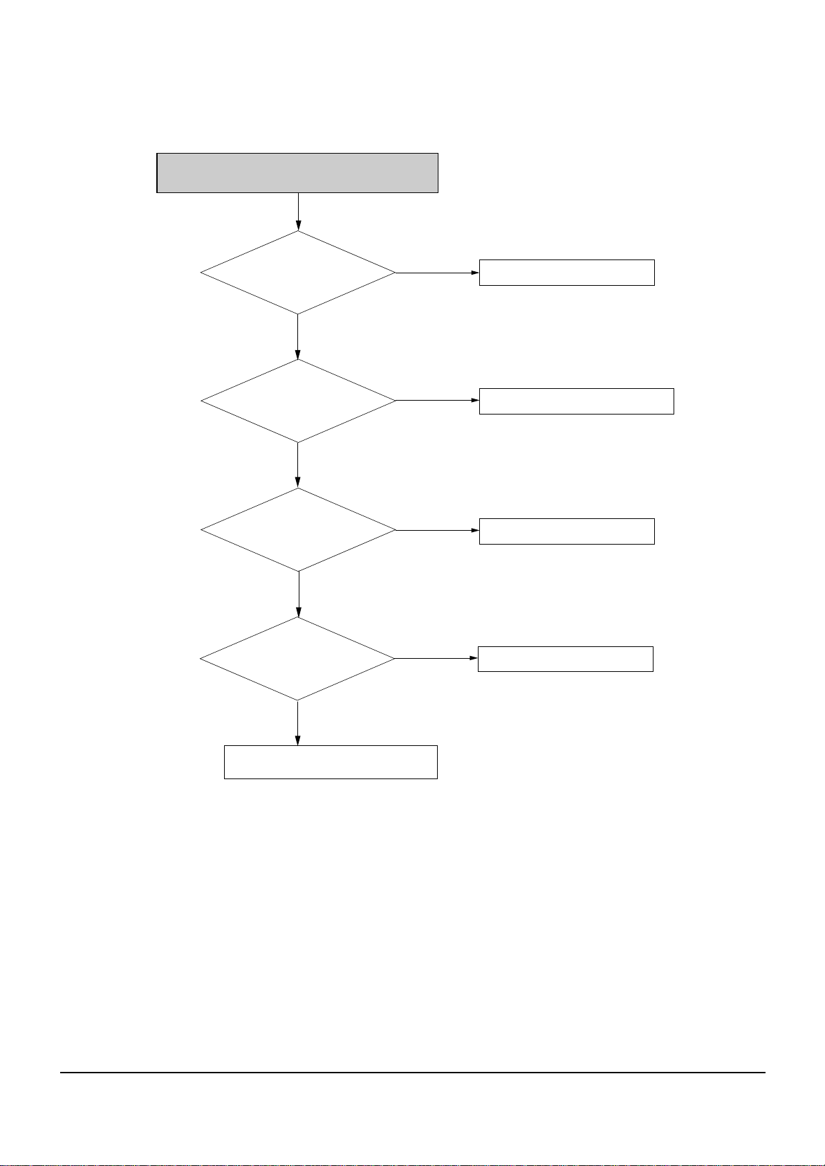
1 pin and 5 pin in CN03 of
Jack PCB has normal level
Check the RCA cable
No
Replace the Main B/D
Analog signals are
inputed normally
VIC05 (Pin 2, Pin 6)
No
No
No
Check the connection between
1 pin and 5 pin in CON03 of
JACK PCB and VIC05
Power is
normal(5V) at VIC05(pin1,34)?
Pin 3 in VIC05 is
in high state?
Check the connection between
VIC05(pin1,34) and power line
(PD102, PL102).
Check the connection between
VIC05(pin3) and VR156.
Yes
Yes
Yes
Yes
No
Video signal of About
P-P 2V appears at Output jack?
(without Connection to TV)
Check the connection between
VIC05 and output jack
Yes
CVBS(Video) output error
# IF Recorder is under PSO(progressive scan output) MODE, it does not
output the CVBS& S-Video, RGB signal.
CVBS(Color-bar)
Troubleshooting
5-3
Check the RCA cable
No
No
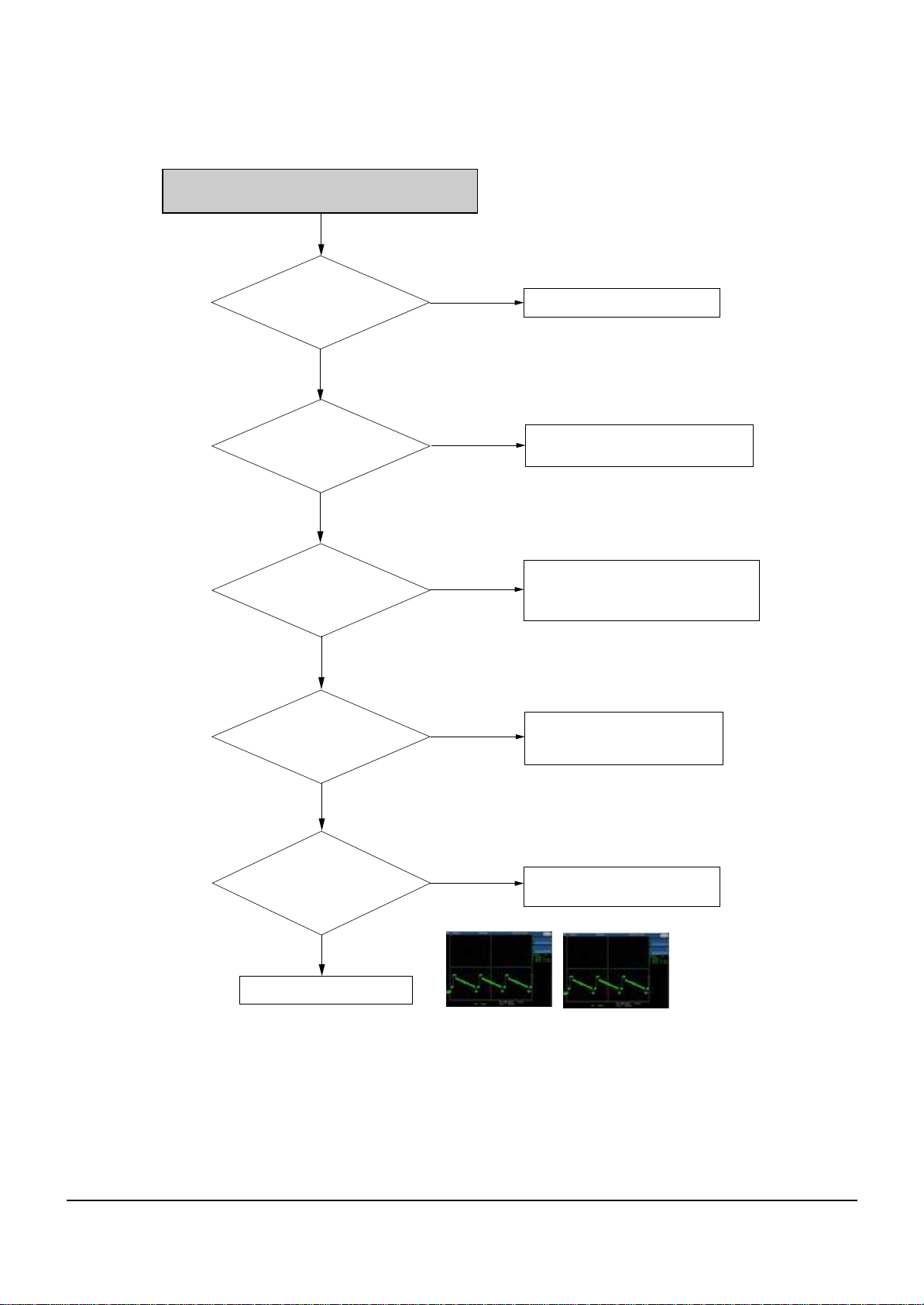
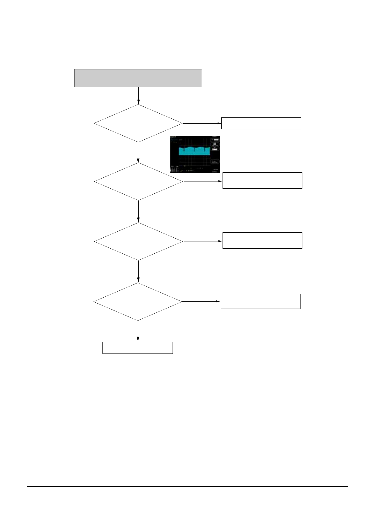
Analong signals are
inputted normally
VIC05(Pin 12/14/16)
No
No
No
Check the connection between
VIC05 (Pin 1, 34) and Power line
(7,8 pin of CON05)
Power is normal (5V) at
VIC05 (Pin 1, 34)?
Pin 15 in VIC05 is
in high state?
Check the connection between
VIC05 and MIC01 56 pin.
Check the connection between
VIC05 and output jack
Yes
Yes
Yes
Yes
Yes
Component (Y, Cb, Cr) output error
2/6/10 Pin in C0N3 of
Jack PCB has normal level?
Video signal of
About P-P 2V appears at Output Jack?
(without connection to TV)
Replace the Main B/D
Check the connection between
2/6/10 pin in C0N3 of JACK PCB
and VIC05
# IF Recorder is under PSO(progressive scan output) MODE, or it does not
output the CVBS& S-Video signal.
Y(Color-bar)
Pb(Color-bar) Pr(Color-bar)
Troubleshooting
5-4
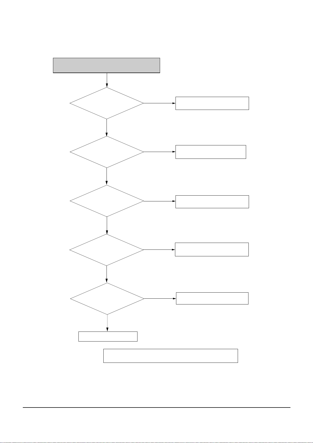
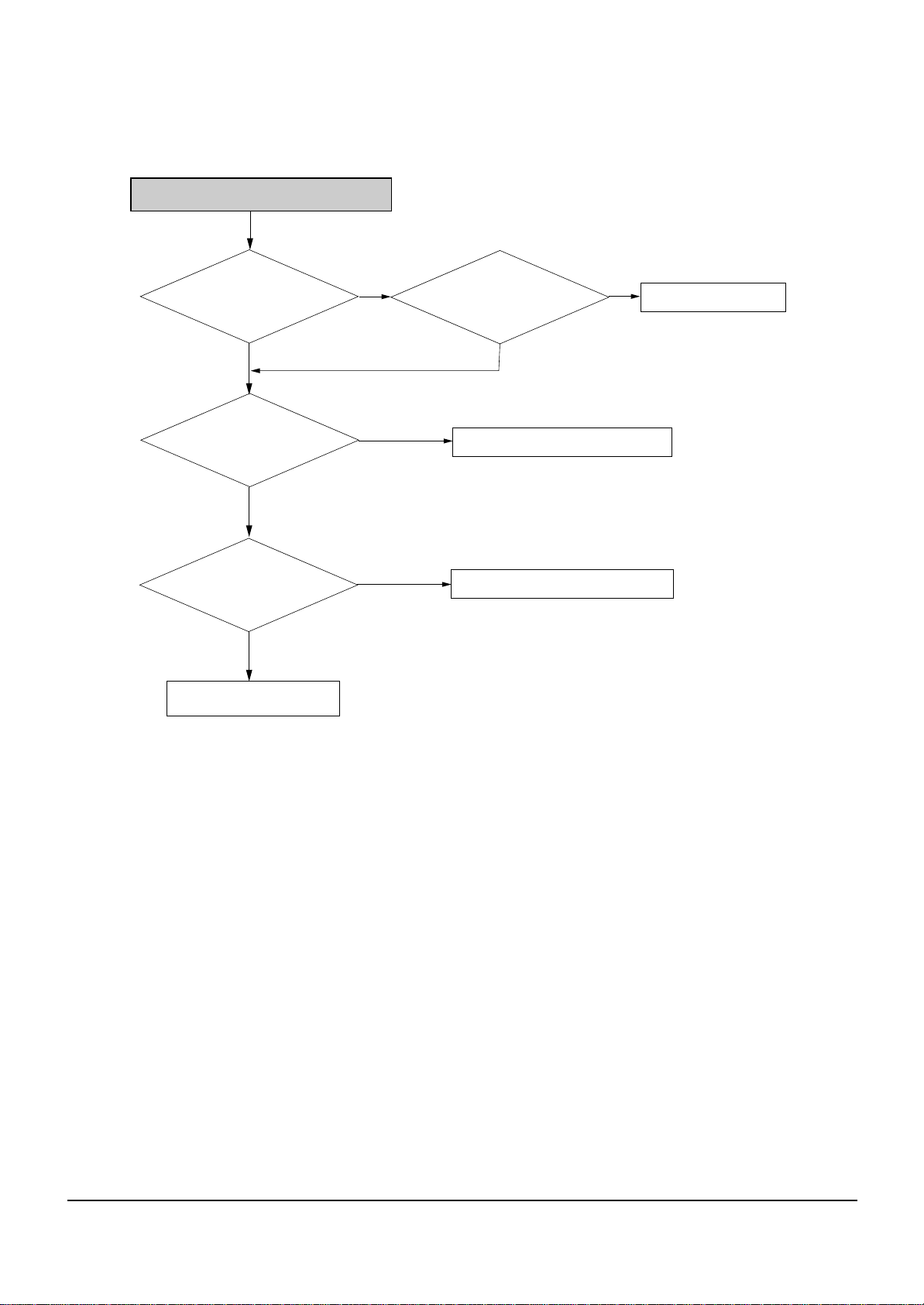
1 pin and 5 pin in CON03 of
jack PCB has normal level?
Analog signals are
inputted normally
VIC05( pin 2,6)
Check the S-Video cable
Replace the Main B/D
No
No
Check the connection between 1 pin and
5 pin in CON03 of JACK PCB and VIC05
Power is normal (5V)
at VIC05(pin 1,34)?
No
No
Check the connection between
VIC05 (pin 1,34) and power line
(7, 8 pin of CON03).
Video signals of about
P-P 2V appears at output jack?
(without connection to TV)
Check the connection between
VIC05 and output jack
Yes
Yes
Yes
Yes
S-Video output error
Yes
No
Pin 3 in VIC05 is
In high state?
Check the connection between
VIC05 (pin 3) and VR156.
Check VIC1 peripheral circuit.
Y(Color-bar)
C(Color-bar)
Troubleshooting
5-5
2, 6 and 10 pin in CON03
of jack PCB
Analog signals are
inputted normally
VIC05(pin 10, 14, 15)
Check the RCA cable
Check Main PCB
No
No
Check the connection between 2,6 and
10 pin in CON03 of Jack PCB and VIC05
No
No
No
Power is
normal at VIC05 1,34?
RGB control signal
level is 4V at 16 pin of
SCART 1 (AV1JACK)?
RGB Video signal
appears at 7, 11, 15 pin of
AV1 output jack?
Check the connection between
1, 34 of VIC05 and power
Check the connection between
VIC05 and output jack
Check the connection between
13pin of SIC01 and AV1 jack
Yes
Yes
Yes
Yes
Yes
AV1 (RGB) Output Error
# IF Recorder is under Component mode (in OSD setup menu),
it does not output RGB out put.
Troubleshooting
5-6
1 pin and 5 pin in CON03 of
jack PCB has normal
level?
Analog signal are
Inputted normally
5pin of SIC05
Analog signal are
out normally
SIC01-29(AV2),30(AV1)
Check the connection between
SIC01 and SCART Jack
-AV1 ; 30 pin of SIC02 and 19 pin of AV1
-AV2 : 29 pin of SIC02 and 40 pin of AV2
Check Main PCB
No
No
Check the connection between 1 pin
and 5 pin of CON03 in Jack PCB and SIC01
No
Check the I2C lin2
(between SIC01-32, 33
and MIC01(Pin 16,18)
Check the SMPS
(AL5.8V)
Yes
Yes
Yes
Check the power
supply to 2, 4, 6pin of SIC01?
No
Yes
AV1, AV2 (CVBS) output error
Troubleshooting
5-7
Pin 15 in VIC01
has normal level?
Pin 3 in VIC01(Input MUX)
has normal level?
Change Main PCB
Check the connection between
pin15 in VIC01 and LINE pin-jack
Check the connection between
VIC01-9, 10, 11 and MIC01(pin 29,30,32)
Control signal of pic9, 10, 11 in
IC201 is as below.
LINE Input : L/H/L
AV2 Input : H/H/H
AV1 Input : L/H/H
PROG Input : L/L/L
No
No
No
CON02-5 of
jack PCB has normal level?
Check the connection between CON02-5
of jack PCB and pin 3 in VIC01
Yes
Yes
Yes
LINE CVBS Video Input Error
Troubleshooting
5-8
Tuner input line signal
is OK? (Jack PCB)
Supplied power for
tuner is OK?
pin1, 3 : 5V
pin16 : 33V
Refer to LINE Video line error
Tuner line connect TV directly
No
No
Check SMPS (AL5.8V and 33V)
No
Video output signal of Tuner is OK?
(jack PCB)
Replace TM (tuner) block.
Yes
Yes
Yes
I2C signal pin 7, 8 of
tuner is OK?
No
Check between pin 7, 8 of tuner
and MIC01.
Yes
Tuner Video Out Abnormal
Tuner Video
Troubleshooting
5-9
Check the Cable
No
No
Yes
Yes
Yes
There's no Digital Audio Out
Check Current Digital Audio
Setting is PCM.
Check Digital Audio data
at CON03 pin 6.
Check 5V at AIC08 pin 14
No
Check the AIC08 peripheral circuits.
Replace MAIN PCB
Set the Bitstream
Check the A/V Receiver
can Decode Current
Bit-Steam
No
Yes
Troubleshooting
5-10
The powers supplied to each
Audio ICs are normal?
Refer to
Audio block diagram, check
whether there is no soldering problem
each IC surrounding parts
in block.
If there is no soldering problem, check each
IC's waveform and change the IC that have problem
or check the peripheral circuits.
Check the power of Audio block
Yes
Yes
No
Audio input/output error
Troubleshooting
5-11
Tuner line signal is OK?
Supplied power
for TIC1 (5V, 33V)is OK?
(jack PCB)
If Audio R/L signal (30,31pin of TIC1)
is normal, check audio line out blocks.
Tuner line connect TV directly.
No
No
Check its power line or around elements
The signal from 11 pin
of tuner is OK?
No
No
Check the SIF signal of tuner
Does AY101 make
18.432 Mhz signal?
(Jack PCB)
Check AY101 or around elements
Yes
Yes
Yes
Yes
Tuner Audio Out Abnormal
 Loading...