


 Loading...
Toshiba America Information Systems, Inc.
Telecommunication Systems Division
Limited Warranty
Toshiba America Information Systems, Inc., (“TAIS”) warrants that this telephone equipment (except for fuses, lamps, batteries, and other consumables) will, upon delivery by TAIS or an authorized TAIS dealer to a retail customer in new condition, be free from defects in material and workmanship for twelve (12) months after delivery. This warranty is void (a) if the equipment is used under other than normal use and maintenance conditions, (b) if the equipment is modified or altered, unless the modification or alteration is expressly authorized by TAIS, (c) if the equipment is subject to abuse, neglect, lightning, electrical fault, or accident, (d) if the equipment is repaired by someone other than TAIS or an authorized TAIS dealer, (e) if the equipment’s serial number is defaced or missing, or (f) if the equipment is installed or used in combination or in assembly with products not supplied by TAIS and which are not compatible or are of inferior quality, design, or performance.
The sole obligation of TAIS or Toshiba Corporation under this warranty, or under any other legal obligation with respect to the equipment, is the repair or replacement by TAIS or its authorized dealer of such defective or missing parts as are causing the malfunction with new or refurbished parts (at their option). If TAIS or one of its authorized dealers does not replace or repair such parts, the retail customer’s sole remedy will be a refund of the price charged by TAIS to its dealers for such parts as are proven to be defective, and which are returned to TAIS through one of its authorized dealers within the warranty period and no later than thirty (30) days after such malfunction, whichever first occurs.
Under no circumstances will the retail customer or any user or dealer or other person be entitled to any direct, special, indirect, consequential, or exemplary damages, for breach of contract, tort, or otherwise. Under no circumstances will any such person be entitled to any sum greater than the purchase price paid for the item of equipment that is malfunctioning.
To obtain service under this warranty, the retail customer must bring the malfunction of the machine to the attention of one of TAIS’ authorized dealers within the twelve (12) month period and no later than thirty (30) days after such malfunction, whichever first occurs. Failure to bring the malfunction to the attention of an authorized TAIS dealer within the prescribed time results in the customer being not entitled to warranty service.
THERE ARE NO OTHER WARRANTIES FROM EITHER TOSHIBA AMERICA INFORMATION SYSTEMS, INC., OR TOSHIBA CORPORATION WHICH EXTEND BEYOND THE FACE OF THIS WARRANTY. ALL OTHER WARRANTIES, EXPRESS OR IMPLIED, INCLUDING THE WARRANTIES OF MERCHANTABILITY, FITNESS FOR A PARTICULAR PURPOSE, AND FITNESS FOR USE, ARE EXCLUDED.
No TAIS dealer and no person other than an officer of TAIS may extend or modify this warranty. No such modification or extension is effective unless it is in writing and signed by the vice president and general manager, Telecommunication Systems Division.
726+,%$ |
Telecommunication Systems Division |
|
|
Digital Business Telephone Solutions
General Description
Software Release 3.1
Software Release 4.3
Software Release 4.3 and ACD
June 2000

Strata DK
General End User Information
The Strata DK Digital Business Telephone System is registered in accordance with the provisions of Part 68 of the Federal Communications Commission’s Rules and Regulations.
FCC Requirements
Means of Connection: The Federal Communications Commission (FCC) has established rules which permit the Strata DK system to be connected directly to the telephone network. Connection points are provided by the telephone company— connections for this type of customer-provided equipment will not be provided on coin lines. Connections to party lines are subject to state tariffs.
Incidence of Harm: If the system is malfunctioning, it may also be disrupting the telephone network. The system should be disconnected until the problem can be determined and repaired. If this is not done, the telephone company may temporarily disconnect service. If possible, they will notify you in advance, but, if advance notice is not practical, you will be notified as soon as possible. You will be informed of your right to file a complaint with the FCC.
Service or Repair: For service or repair, contact your local Toshiba telecommunications distributor. To obtain the nearest Toshiba telecommunications distributor in your area, call Toshiba America Information Systems, Inc., Telecommunication Systems Division in Irvine, CA (949) 583-3700.
Telephone Network Compatibility: The telephone company may make changes in its facilities, equipment, operations, and procedures. If such changes affect the compatibility or use of the Strata DK system, the telephone company will notify you in advance to give you an opportunity to maintain uninterrupted service.
Notification of Telephone Company: Before connecting a Strata DK system to the telephone network, the telephone company may request the following:
1.Your telephone number.
2.FCC registration number:
♦Strata DK may be configured as a Key or Hybrid telephone system. The appropriate configuration for your system is dependent upon your operation of the system.
♦If the operation of your system is only manual selection of outgoing lines, it may be registered as a Key telephone system.
♦If your operation requires automatic selection of outgoing lines, such as dial access, Least Cost Routing, Pooled Line Buttons, etc., the system must be registered as a Hybrid telephone system. In addition to the above, certain features (tie Lines, Off-premises Stations, etc.) may also require Hybrid telephone system registration in some areas.
♦If you are unsure of your type of operation and/or the appropriate FCC registration number, contact your local Toshiba telecommunications distributor for assistance.
DK14 and DK40i
Key system: CJ6MLA-74479-KF-E Hybrid: CJ6MLA-74478-MF-E
DK424i
Key system: CJ69XA-10242-KF-E Hybrid: CJ69XA-10243-MF-E PBX: CJ6JPN-22758-PF-E
3.Ringer equivalence number: 0.3B. The ringer equivalence number (REN) is useful to determine the quantity of devices which you may connect to your telephone line and still have all of those devices ring when your number is called. In most areas, but not all, the sum of the RENs of all devices connected to one line should not exceed five (5.0B). To be certain of the number of devices you may connect to your line, as determined by the REN, you should contact your local telephone company to ascertain the maximum REN for your calling area.
4.Network connection information USOC jack required: RJ1CX, RJ2EX, RJ2GX, RJ48C, RJ48X, RJ11, RJ14C, RJ21X (see Network Requirements in this document). Items 2, 3 and 4 are also indicated on the equipment label.
Radio Frequency Interference
Warning: This equipment generates, uses, and can radiate radio frequency energy and if not installed and used in accordance with the manufacturer’s instruction manual, may cause interference to radio communications. It has been tested and found to comply with the limits for a Class A computing device pursuant to Subpart J of Part 15 of FCC Rules, which are designed to provide reasonable protection against such interference when operated in a commercial environment. Operation of this equipment in a residential area is likely to cause interference, in which case, the user, at his/her own expense, will be required to take whatever measures may be required to correct the interference.
This system is listed with Underwriters Laboratory. |
|
|
|
|
UL Requirement: If wiring from any telephone exits the building or is |
U |
|
||
subject to lightning or other electrical surges, then secondary protection |
L |
|||
is required. Secondary protection is also required on DID, OPS, and tie |
® |
|||
lines. (Additional information is provided in this manual.) |
|
|
|
|
Important Notice — Music-On-Hold
In accordance with U.S. Copyright Law, a license may be required from
the American Society of Composers, Authors and Publishers, or other similar organization, if radio or TV broadcasts are transmitted through the music-on-hold feature of this telecommunication system. Toshiba America Information Systems, Inc., hereby disclaims any liability arising out of the failure to obtain such a license.
CP01, Issue 8, Part I Section 14.1
Notice: The Industry Canada label identifies certified equipment. This certification means that the equipment meets certain telecommunications network protective, operational and safety requirements as prescribed in the appropriate Terminal Equipment Technical Requirements document(s). The Department does not guarantee the Equipment will operate to the user’s satisfaction.
Before installing this equipment, users should ensure that it is permissible to be connected to the facilities of the local telecommunications company. The equipment must also be installed using an acceptable method of connection. The customer should be aware that compliance with the above conditions may not prevent degradation of service in some situations.
Repairs to certified equipment should be coordinated by a representative designated by the supplier. Any repairs or alterations made by the user to this equipment, or equipment malfunctions, may give the telecommunications company cause to request the user to disconnect the equipment.
Users should ensure for their own protection that the electrical ground connections of the power utility, telephone lines and internal metallic water pipe system, if present, are connected together. This precaution may be particularly important in rural areas.
CAUTION! Users should not attempt to make such connections themselves, but should contact the appropriate electric inspection authority, or electrician, as appropriate.
CP01, Issue 8, Part I Section 14.2
Notice: The Ringer Equivalence Number (REN) assigned to each terminal device provides an indication of the maximum number of terminals allowed to be connected to a telephone interface. The terminal on an interface may consist of any combination of devices subject only to the requirement that the sum of the Ringer Equivalence Numbers of all the Devices does not exceed 5.
Publication Information
Toshiba America Information Systems, Inc., Telecommunication Systems Division, reserves the right, without prior notice, to revise this information publication for any reason, including, but not limited to, utilization of new advances in the state of technical arts or to simply change the design of this document.
Further, Toshiba America Information Systems, Inc., Telecommunication Systems Division, also reserves the right, without prior notice, to make such changes in equipment design or components as engineering or manufacturing methods may warrant.
DKA-GD-GNDES-VF 4010451
Version F.2, June 2000
Version F.1, May 2000
Version F, May 2000 (Release 4.3)
Version E.2, March 2000 (Release 4.15)
Version E, May 1999
Version D, August 1998
Version C, March 1998
Version B, October 1997
Version A.1, May 1997
Version A, March 1997
© Copyright 2000
Toshiba America Information Systems, Inc.
Telecommunication Systems Division
All rights reserved. No part of this manual, covered by the copyrights hereon, may be reproduced in any form or by any means—graphic, electronic, or mechanical, including recording, taping, photocopying, or information retrieval systems—without express written permission of the publisher of this material.
Strata AirLink and Call Center Viewer are trademarks of Toshiba America Information Systems, Inc. Stratagy is a registered trademark of Toshiba America Information Systems, Inc. Strata is a registered trademark of Toshiba Corporation.
Trademarks, registered trademarks, and service marks are the property of their respective owners.

Contents
Introduction |
|
Organization ........................................................................................................................................... |
ix |
Conventions............................................................................................................................................. |
x |
Related Documents/Media ..................................................................................................................... |
xi |
General Descriptions ....................................................................................................................... |
xi |
Installation and Programming ......................................................................................................... |
xi |
Feature Description.......................................................................................................................... |
xi |
User Guides for:............................................................................................................................... |
xi |
Quick Reference Guides for: .......................................................................................................... |
xii |
CD-ROMs....................................................................................................................................... |
xii |
Chapter 1 – Strata DK14 |
|
KSU Architecture.................................................................................................................................... |
2 |
Digital Telephone/Central Office (CO) Line Circuits ...................................................................... |
2 |
Optional Printed Circuit Boards.............................................................................................................. |
3 |
Central Office Line/Digital Telephone Interface Unit (QCDU2) .................................................... |
3 |
Standard Telephone Interface Unit (QSTU2)................................................................................... |
3 |
DTMF Receiver/ABR Tone Detector Unit (QRCU3)...................................................................... |
3 |
Auto Attendant Feature Key (QKYS1) ............................................................................................ |
3 |
Serial Interface Board (WSIU1) ....................................................................................................... |
3 |
Power Considerations.............................................................................................................................. |
4 |
Reserve Power .................................................................................................................................. |
4 |
Power Failure Interface .................................................................................................................... |
4 |
Music-on-Hold (MOH) Interface ..................................................................................................... |
4 |
Paging Interface ................................................................................................................................ |
4 |
Flexible Relay Contacts.................................................................................................................... |
4 |
Maximum Line/Station Configurations .................................................................................................. |
5 |
Network Requirements............................................................................................................................ |
5 |
Functional Block Diagram ...................................................................................................................... |
6 |
System Technology ................................................................................................................................. |
7 |
Pulse Code Modulation .................................................................................................................... |
7 |
Custom Electronic Circuitry............................................................................................................. |
7 |
Stored Program Control.................................................................................................................... |
7 |
Microprocessors................................................................................................................................ |
7 |
Maintenance and Programming .............................................................................................................. |
8 |
DKi Admin/DKi Backup .................................................................................................................. |
8 |
Strata DK General Description 6/00 |
i |

Contents |
|
Chapter 2 – Strata DK40i |
|
Chapter 2 – Strata DK40i |
|
Base KSU Architecture ......................................................................................................................... |
10 |
Digital Telephone Circuits.............................................................................................................. |
10 |
Central Office (CO) Line Circuits (TCOU/TDDU/TBSU/TBUU) ................................................ |
10 |
Standard Telephone Interface Unit (KSTU2)................................................................................. |
11 |
DTMF/ABR Tone Detection Receiver (K5RCU and K5RCU2) ................................................... |
11 |
Feature Key (KKYS) ...................................................................................................................... |
12 |
SMDR, SMDI, ACD/MIS and Maintenance DKi Admin/Modem (TTY) Interface (TSIU) ......... |
12 |
Expansion KSU Architecture ................................................................................................................ |
12 |
Station and Line Capacities................................................................................................................... |
12 |
ISDN BRI Lines ............................................................................................................................. |
13 |
Peripherals............................................................................................................................................. |
14 |
Power Considerations............................................................................................................................ |
15 |
Power Supply/Reserve Power ........................................................................................................ |
15 |
Power Failure Interface .................................................................................................................. |
16 |
Music-on-Hold Interface ................................................................................................................ |
16 |
Functional Block Diagram .................................................................................................................... |
16 |
Network Requirements.......................................................................................................................... |
18 |
System Technology ............................................................................................................................... |
18 |
Pulse Code Modulation .................................................................................................................. |
18 |
Custom Electronic Circuitry........................................................................................................... |
18 |
Stored Program Control.................................................................................................................. |
18 |
Microprocessors.............................................................................................................................. |
18 |
Maintenance and Programming ............................................................................................................ |
18 |
DKi Admin/DKi Backup ................................................................................................................ |
18 |
StrataControl................................................................................................................................... |
18 |
Chapter 3 – Strata DK424i |
|
Architecture........................................................................................................................................... |
19 |
Processor PCBs ..................................................................................................................................... |
20 |
Processor PCB Subassemblies........................................................................................................ |
20 |
Cabinet Slots ......................................................................................................................................... |
21 |
Base Cabinet ................................................................................................................................... |
21 |
Expansion Cabinets ........................................................................................................................ |
22 |
Printed Circuit Boards (PCBs) ....................................................................................................... |
22 |
Maximum Station/Line Capacities........................................................................................................ |
22 |
ISDN BRI Circuit Capacity Guidelines ................................................................................................ |
25 |
ISDN BRI CIrcuit Capacity Guidelines................................................................................................ |
27 |
Remote Expansion Cabinet Unit........................................................................................................... |
30 |
Power Considerations............................................................................................................................ |
30 |
Reserve Power ................................................................................................................................ |
30 |
Primary/Reserve Power Cabinet Hardware .......................................................................................... |
31 |
DK424 and DK424i Hardware Compatibility ...................................................................................... |
34 |
Functional Block Diagrams................................................................................................................... |
35 |
Maintenance and Programming ............................................................................................................ |
38 |
DKi Admin/DKi Backup ................................................................................................................ |
38 |
StrataControl................................................................................................................................... |
38 |
ii
Strata DK General Description 6/00

|
Contents |
|
Chapter 4 – Universal Slot PCBs |
Chapter 4 – Universal Slot PCBs |
|
Station PCBs ......................................................................................................................................... |
39 |
Digital Telephone Interface Unit (PDKU2) ................................................................................... |
39 |
Digital/Standard Telephone Interface Unit (RDSU) ...................................................................... |
39 |
Strata AirLink Wireless Interface Unit (RWIU) ............................................................................ |
40 |
CO Line/Digital Telephone Interface Unit (KCDU) (DK40i only) ............................................... |
40 |
Electronic Telephone Interface Unit (PEKU) ................................................................................ |
40 |
Standard/Electronic Telephone Interface Unit (PESU).................................................................. |
40 |
Standard Telephone Interface Unit (RSTU2) ................................................................................. |
40 |
Console PCBs........................................................................................................................................ |
41 |
Attendant Console Interface Unit (RATU, DK424i only) ............................................................. |
41 |
CO Line PCBs....................................................................................................................................... |
41 |
Caller ID Interface Unit (RCIU2)................................................................................................... |
41 |
Loop Start CO Line Interface Unit (RCOU) .................................................................................. |
42 |
Ground/Loop Start Interface CO Line Interface Unit (RGLU2) .................................................... |
42 |
Direct Inward Dialing Interface Unit (RDDU)............................................................................... |
42 |
Tie Line Unit (REMU) ................................................................................................................... |
42 |
Voice Over IP Gateway (BVPU).................................................................................................... |
43 |
T1/DS-1 Interface Unit (RDTU2) .................................................................................................. |
43 |
ISDN Primary Rate Interface Unit (RPTU) ................................................................................... |
43 |
ISDN S/T-type Basic Rate Interface Unit (RBSU) ........................................................................ |
43 |
ISDN U-type Basic Rate Interface Unit (RBUU) .......................................................................... |
44 |
Enhanced 911 CAMA Trunk Interface Unit (RMCU/RCMS)....................................................... |
44 |
Summary of PCBs and Subassemblies ................................................................................................. |
45 |
Option Interface PCBs .......................................................................................................................... |
48 |
Option Interface Unit (PIOU)......................................................................................................... |
48 |
Simplified Option Interface Unit (PIOUS)..................................................................................... |
48 |
External Page Interface Unit (PEPU) ............................................................................................. |
48 |
Single Serial Interface Unit (RSSU)............................................................................................... |
48 |
Serial Interface Unit (RSIU, DK424i only).................................................................................... |
49 |
Option Interface PCB Compatibility .............................................................................................. |
50 |
Chapter 5 – Stations and Peripherals |
|
Digital Telephones ................................................................................................................................ |
52 |
DKT2001 ........................................................................................................................................ |
53 |
Liquid Crystal Display (LCD) Telephones ........................................................................................... |
54 |
Speakerphones....................................................................................................................................... |
55 |
Peripherals............................................................................................................................................. |
56 |
Digital Telephone Upgrade Options ..................................................................................................... |
57 |
Digital Add-on Module (DADM)................................................................................................... |
57 |
Integrated PC Interface (RPCI-DI)................................................................................................. |
57 |
Headset/Loud Ringing Bell Interface (HHEU) .............................................................................. |
57 |
Microphone Unit (RFDM).............................................................................................................. |
57 |
Speaker Off-hook Call Announce (DVSU).................................................................................... |
58 |
Stand-alone Data Interface Unit (PDIU-DS) ........................................................................................ |
58 |
Cordless Digital Telephones ................................................................................................................. |
58 |
DKT2104-CT.................................................................................................................................. |
58 |
DKT2004-CT.................................................................................................................................. |
59 |
Strata AirLink Wireless Handset .......................................................................................................... |
59 |
Strata DK General Description 6/00 |
iii |

Contents |
|
Chapter 6 – System Features |
|
Features........................................................................................................................................... |
60 |
Strata AirLink Wireless Systems.................................................................................................... |
60 |
PC Attendant Console (DK-PCATT).................................................................................................... |
61 |
Direct Station Selection (DSS) Console ............................................................................................... |
62 |
Door Phone (MDFB)............................................................................................................................. |
63 |
Door Phone and Lock Control Unit (DDCB) ....................................................................................... |
63 |
External Speaker (HESB) ..................................................................................................................... |
63 |
Toshiba Stratagy and Stratagy DK Voice Processing........................................................................... |
63 |
Cabling and Connectors ........................................................................................................................ |
64 |
Station and Peripheral Specifications.................................................................................................... |
64 |
Chapter 6 – System Features |
|
Abandoned Call Numbers ..................................................................................................................... |
65 |
Account Codes (Forced/Voluntary/Verified)........................................................................................ |
65 |
Alarm Sensor (DK40i, DK424i only) ................................................................................................... |
65 |
Alternate Answer Point ......................................................................................................................... |
66 |
Amplified Conference Interface (DK40i, DK424i only) ...................................................................... |
66 |
Auto Attendant (Built-in) ...................................................................................................................... |
66 |
Automatic Call Distribution (ACD)...................................................................................................... |
67 |
Insight DK ...................................................................................................................................... |
67 |
Automatic Number Identification (ANI) .............................................................................................. |
68 |
Automatic Release from Hold............................................................................................................... |
69 |
Background Music (BGM) ................................................................................................................... |
69 |
Caller ID................................................................................................................................................ |
69 |
Centrex/PBX Compatible...................................................................................................................... |
70 |
Centrex Ringing Repeat ........................................................................................................................ |
70 |
Computer Telephony Integration (CTI) ................................................................................................ |
70 |
Digital Telephone Integrated PC Interface ..................................................................................... |
70 |
StrataLink ....................................................................................................................................... |
70 |
Conferencing ......................................................................................................................................... |
71 |
Credit Card Calling ............................................................................................................................... |
71 |
Data Switching ...................................................................................................................................... |
71 |
Day/Night Modes .................................................................................................................................. |
72 |
Delayed Ringing.................................................................................................................................... |
72 |
Dialed Number Identification Service (DNIS) |
|
(DK40i, DK424i only).................................................................................................................... |
72 |
External Telephone Network Numbers .......................................................................................... |
73 |
Voice Mail ...................................................................................................................................... |
73 |
Direct Inward Dialing (DID) Lines (DK40i, DK424i only) ................................................................. |
73 |
Direct Inward System Access (DISA) .................................................................................................. |
73 |
Distinctive CO Line/Directory Number Ringing .................................................................................. |
74 |
Door Lock Control ................................................................................................................................ |
74 |
Door Phones (MDFB) ........................................................................................................................... |
74 |
DTMF Back Tone ................................................................................................................................. |
74 |
DTMF and Dial Pulse CO Line Compatible......................................................................................... |
74 |
DTMF Signal Time (80/160 ms)........................................................................................................... |
74 |
Emergency Ringdown ........................................................................................................................... |
75 |
Enhanced 911 (E911) Service (DK40i, DK424i only) ......................................................................... |
75 |
Adjunct Equipment Operation........................................................................................................ |
75 |
Direct CAMA Connections ............................................................................................................ |
76 |
iv
Strata DK General Description 6/00

|
Contents |
|
Chapter 6 – System Features |
ISDN Operation .............................................................................................................................. |
76 |
External Page Zones.............................................................................................................................. |
76 |
Flexible Button Assignment.................................................................................................................. |
76 |
Flexible Directory Numbers.................................................................................................................. |
76 |
Flexible Line Ringing Assignment ....................................................................................................... |
77 |
Group Paging ........................................................................................................................................ |
77 |
Handsfree Directory Number Paths ...................................................................................................... |
77 |
Hospitality Management Information System (HMIS)......................................................................... |
77 |
Hotline Service...................................................................................................................................... |
78 |
Integrated Services Digital Network (ISDN) |
|
(DK40i, DK424i only)................................................................................................................... |
78 |
ISDN Primary Rate Interface (PRI)................................................................................................ |
79 |
ISDN Basic Rate Interface (BRI) ................................................................................................... |
79 |
Call-by-Call Service Selection ....................................................................................................... |
79 |
Non-Facility Associated Signaling (NFAS) ................................................................................... |
80 |
Calling Number Identification Services (CNIS) ............................................................................ |
80 |
Least Cost Routing (LCR) .................................................................................................................... |
81 |
Line Groups........................................................................................................................................... |
81 |
Line Queuing......................................................................................................................................... |
81 |
Live System Programming.................................................................................................................... |
81 |
Memory Protection................................................................................................................................ |
82 |
Message Waiting ................................................................................................................................... |
82 |
Multiple Directory Numbers ................................................................................................................. |
82 |
Primary Directory Number [PDN] ................................................................................................. |
82 |
Secondary Directory Number [SDN] ............................................................................................. |
82 |
Phantom Directory Number [PhDN] .............................................................................................. |
83 |
Multiple FCC Registration.................................................................................................................... |
84 |
Music-on-hold (MOH) .......................................................................................................................... |
84 |
Night Ringing Over External Page ....................................................................................................... |
84 |
Night Ringing Over Selected Page Zones............................................................................................. |
84 |
Non-blocking Talk Paths....................................................................................................................... |
84 |
Off-premises Station ............................................................................................................................. |
84 |
Outgoing Call Restriction ..................................................................................................................... |
85 |
Pooled CO Line Button ......................................................................................................................... |
85 |
Power Failure Transfer.......................................................................................................................... |
85 |
Privacy/Non-privacy Calling ................................................................................................................ |
85 |
Relay Service ........................................................................................................................................ |
86 |
External Page/Door Lock Control .................................................................................................. |
86 |
Night Relay/Hold Relay ................................................................................................................. |
86 |
Remote Administration/Maintenance ................................................................................................... |
86 |
Reserve Power....................................................................................................................................... |
86 |
Simplified Message Desk Interface (SMDI)......................................................................................... |
86 |
Better Port Usage............................................................................................................................ |
87 |
Improves Call Coverage ................................................................................................................. |
87 |
Streamlines Messaging Procedures ................................................................................................ |
87 |
Speed Dial ............................................................................................................................................. |
87 |
System Speed Dial.......................................................................................................................... |
87 |
Station Speed Dial .......................................................................................................................... |
87 |
Station Hunting ..................................................................................................................................... |
88 |
Serial Hunt...................................................................................................................................... |
88 |
Strata DK General Description 6/00 |
v |

Contents |
|
Chapter 7 – Station Features |
|
Distributed Hunt (DH).................................................................................................................... |
88 |
Station Message Detail Recording (SMDR) ......................................................................................... |
88 |
Station Relocation ................................................................................................................................. |
89 |
StrataControl ......................................................................................................................................... |
89 |
System Programming through a Station ............................................................................................... |
89 |
System Program Administration Software (DKi Admin)..................................................................... |
89 |
T1 Interface (DK40i, DK424i only)...................................................................................................... |
90 |
Tandem CO Line Connections.............................................................................................................. |
90 |
Tenant Service....................................................................................................................................... |
90 |
Tie Lines................................................................................................................................................ |
91 |
Toll Restriction...................................................................................................................................... |
91 |
Toll Restriction Override by System Speed Dial .................................................................................. |
91 |
Traveling Class of Service .................................................................................................................... |
91 |
Unrestricted Call Transfer to Directory Numbers................................................................................. |
92 |
Voice First or Tone Signaling ............................................................................................................... |
92 |
Voice Mail Integration .......................................................................................................................... |
92 |
Automated Attendant...................................................................................................................... |
92 |
ANI/DNIS Routing to Voice Mailbox............................................................................................ |
92 |
Call Forward to Voice Mailbox...................................................................................................... |
92 |
Message Waiting Indication ........................................................................................................... |
93 |
Voice Mail Control via Station....................................................................................................... |
93 |
Chapter 7 – Station Features |
|
Account Code Button............................................................................................................................ |
97 |
Add-on Module (DADM) ..................................................................................................................... |
97 |
Alert Signal Button ............................................................................................................................... |
97 |
Automatic Busy Redial (ABR) ............................................................................................................. |
97 |
Automatic Callback (ACB)................................................................................................................... |
98 |
Automatic Hold..................................................................................................................................... |
98 |
Automatic Line Selection...................................................................................................................... |
98 |
Background Music (BGM) with Station Control.................................................................................. |
98 |
Busy Override ....................................................................................................................................... |
98 |
Busy Station Transfer/Busy Station Ringing ........................................................................................ |
98 |
Call Forwarding .................................................................................................................................... |
99 |
All Calls .......................................................................................................................................... |
99 |
Busy ................................................................................................................................................ |
99 |
No Answer...................................................................................................................................... |
99 |
Busy/No Answer............................................................................................................................. |
99 |
Fixed ............................................................................................................................................. |
100 |
External Call ................................................................................................................................. |
100 |
Call Park Orbits................................................................................................................................... |
100 |
Park and Page ............................................................................................................................... |
100 |
Auto Park ...................................................................................................................................... |
100 |
Call Pickup .......................................................................................................................................... |
100 |
Call Pickup Groups ............................................................................................................................. |
101 |
Call Transfer with Camp-on................................................................................................................ |
101 |
Call Transfer Immediate ..................................................................................................................... |
101 |
Call Transfer Music or Ringing Option .............................................................................................. |
101 |
Call Transfer Recall ............................................................................................................................ |
101 |
Centrex/PBX Features......................................................................................................................... |
101 |
vi
Strata DK General Description 6/00
|
Contents |
Chapter 8 – PC Attendant Console Features |
|
Conferencing ....................................................................................................................................... |
102 |
Continuous Dual-tone Multi-frequency (DTMF) Tone ...................................................................... |
102 |
Data Call Button.................................................................................................................................. |
102 |
Direct Station Selection (DSS) Buttons .............................................................................................. |
102 |
Direct Station Selection (DSS) Console Features ............................................................................... |
102 |
Directory Number [DN] Buttons ........................................................................................................ |
103 |
DISA Security Code Revision ............................................................................................................ |
103 |
Distinctive LED Color and Flash Indications ..................................................................................... |
103 |
Distinctive Station Ringing ................................................................................................................. |
103 |
Do Not Disturb (DND)........................................................................................................................ |
103 |
Do Not Disturb (DND) Override ........................................................................................................ |
103 |
DP/DTMF Mode Change .................................................................................................................... |
103 |
Exclusive Hold .................................................................................................................................... |
103 |
Executive Override.............................................................................................................................. |
104 |
Feature Prompting with Soft Keys...................................................................................................... |
104 |
Flash Button ........................................................................................................................................ |
104 |
Handsfree Answerback ....................................................................................................................... |
104 |
Hearing Aid Compatible ..................................................................................................................... |
104 |
Liquid Crystal Display (LCD) Features.............................................................................................. |
104 |
Microphone Cut-off Button................................................................................................................. |
104 |
Microphone (External Unit)................................................................................................................ |
105 |
Modem Button .................................................................................................................................... |
105 |
Modular Handset and Line Cords ....................................................................................................... |
105 |
Modular Headset ................................................................................................................................. |
105 |
Off-hook Call Announce (OCA)......................................................................................................... |
105 |
Handset Mode............................................................................................................................... |
105 |
Speaker Mode ............................................................................................................................... |
106 |
On-hook Dialing.................................................................................................................................. |
106 |
Personal Computer Interface (RPCI-DI)............................................................................................. |
106 |
Pooled Line Buttons ............................................................................................................................ |
106 |
Private CO Lines ................................................................................................................................. |
106 |
Push-button Dialing ............................................................................................................................ |
106 |
Release Button .................................................................................................................................... |
106 |
Release/Answer Button ....................................................................................................................... |
107 |
Remote Retrieval of Held/Parked Calls .............................................................................................. |
107 |
Repeat Last Number Dialed ................................................................................................................ |
107 |
Ringing Line Preference ..................................................................................................................... |
107 |
Saved Number Redial ......................................................................................................................... |
107 |
Speed Dial Buttons.............................................................................................................................. |
107 |
Telephone Application Programming Interface (TAPI) Compatibility .............................................. |
108 |
Timed Reminders ................................................................................................................................ |
108 |
Toll Restriction Override Code Revision............................................................................................ |
108 |
User Programmable Feature Buttons .................................................................................................. |
108 |
Chapter 8 – PC Attendant Console Features |
|
Answer Button .................................................................................................................................... |
113 |
Answer Priority ................................................................................................................................... |
113 |
Answer Prompting .............................................................................................................................. |
113 |
Attendant Conference Setup ............................................................................................................... |
114 |
Auto Day/Night Mode Switching ....................................................................................................... |
114 |
Strata DK General Description 6/00 |
vii |

Contents |
|
Chapter 8 – PC Attendant Console Features |
|
Auto Dialing........................................................................................................................................ |
114 |
Busy Lamp Field (BLF) Display......................................................................................................... |
114 |
Call Waiting Count ............................................................................................................................. |
114 |
Color CRT Display ............................................................................................................................. |
114 |
Dial “O” For Attendant ....................................................................................................................... |
114 |
Dial Outside Number For Station User............................................................................................... |
114 |
Direct Station Selection (DSS)............................................................................................................ |
115 |
Directory Display and Dialing ............................................................................................................ |
115 |
DTMF Signaling from Dial Pad.......................................................................................................... |
115 |
Emergency Calls ................................................................................................................................. |
115 |
Emergency Page.................................................................................................................................. |
115 |
Feature On-Line Help ......................................................................................................................... |
115 |
Feature Prompting with Soft Keys...................................................................................................... |
115 |
Flexible Programmable Buttons.......................................................................................................... |
116 |
Headset Operation ............................................................................................................................... |
116 |
Hold Button ......................................................................................................................................... |
116 |
Hold Timer Display............................................................................................................................. |
116 |
Incoming Call Identification ............................................................................................................... |
116 |
Incoming Call Statistics ...................................................................................................................... |
116 |
Interposition Call Transfer .................................................................................................................. |
116 |
Join Button .......................................................................................................................................... |
116 |
Keyboard or Mouse Operation............................................................................................................ |
117 |
Load Sharing ....................................................................................................................................... |
117 |
Loop Hold Display .............................................................................................................................. |
117 |
Message Center ................................................................................................................................... |
117 |
Multi-tasking ....................................................................................................................................... |
117 |
Name or Number Dialing.................................................................................................................... |
118 |
Overflow ............................................................................................................................................. |
118 |
Override............................................................................................................................................... |
118 |
Position Busy Mode ............................................................................................................................ |
118 |
Release Button .................................................................................................................................... |
118 |
Speed Dial Calling .............................................................................................................................. |
118 |
Split/Switch Button ............................................................................................................................. |
119 |
Three-way Calling............................................................................................................................... |
119 |
Through Dialing .................................................................................................................................. |
119 |
Transfer Direct to Voice Mail ............................................................................................................. |
119 |
Trunk Group Busy Indication ............................................................................................................. |
119 |
Trunk Group Control........................................................................................................................... |
119 |
Volume Control................................................................................................................................... |
119 |
Appendix – General Specifications ......................................................................................... |
121 |
Network Requirements........................................................................................................................ |
122 |
Customer-supplied Peripherals and Interfaces.................................................................................... |
124 |
Station Specifications.......................................................................................................................... |
125 |
Glossary ............................................................................................................................................... |
131 |
Index........................................................................................................................................................ |
135 |
viii
Strata DK General Description 6/00

Introduction
This General Description provides an overview of the Strata DK telephone systems, associated hardware, system and station features. These systems include:
♦Strata DK14
♦Strata DK40i
♦Strata DK424i
Organization
This document is divided into the following major topics:
♦Chapter 1 – Strata DK14 describes the Strata DK14 overall system and covers the basics of: capacities, system expansion and configuration, power requirements, technology, and maintenance.
♦Chapter 2 – Strata DK40i describes the overall system and the basic capacities, system expansion and configuration, power requirements, technology, and maintenance.
♦Chapter 3 – Strata DK424i describes this new system and covers basic capacities, system expansion and configuration, technology, power requirements, maintenance, and programming.
♦Chapter 4 – Universal Slot PCBs provides information about Printed Circuit Boards (PCBs) that can be installed in the universal slots of the Strata DK systems.
♦Chapter 5 – Stations and Peripherals describes the most recent Toshiba-proprietary stations and peripherals, customer-supplied peripherals, as well as cabling and connectors. Includes information on system tones and data interface specifications.
♦Chapter 6 – System Features describes the features which are available system-wide.
♦Chapter 7 – Station Features describes the features which are available as stations features and shows the types of stations on which they are available.
♦Chapter 8 – PC Attendant Console Features describes the features available from a PC Attendant Console, digital telephones, and the older DK Attendant Console.
♦Appendix – Specifications contains reference information for the DK14, DK40i, and DK424i systems and compatible stations.
Strata DK General Description 6/00 |
ix |

Introduction
Conventions
Conventions
Conventions |
Description |
|
|
|
|
Note |
Elaborates specific items or references other information. Within some |
|
tables, general notes apply to the entire table and numbered notes apply to |
||
|
specific items. |
|
|
|
|
Important! |
Calls attention to important instructions or information. |
|
|
|
|
[DN] |
Represents any Directory Number button, also known as an extension or |
|
intercom number. |
||
|
||
|
|
|
[PDN] |
Represents any Primary Directory Number button (the extension number for |
|
the telephone). |
||
|
||
|
|
|
[SDN] |
Represents any Secondary appearance of a PDN. A PDN which appears on |
|
another telephone is considered an SDN. |
||
|
||
|
|
|
[PhDN] |
Represents any Phantom Directory Number button (an additional DN). |
|
|
|
|
[ ] |
Brackets indicate a variable button. Example: [DN] represents the actual |
|
Directory Number, such as [301]. |
||
|
||
|
|
|
$ULDO %ROG |
Represents telephone buttons. |
|
|
|
|
Courier |
Shows a computer keyboard entry or screen display. |
|
|
|
|
|
shows a multiple PC keyboard or phone button entry. Entries without spaces |
|
|
between them show a simultaneous entry. |
|
+ |
Example: Delete+Enter. |
|
|
Entries with spaces between them show a sequential entry. |
|
|
Example: + . |
|
|
|
|
Tilde (~) |
Means “through.” Example: 350~640 Hz frequency range. |
|
|
|
|
|
Grey words within the printed text denote cross-references. In the electronic |
|
See Figure 10 |
version of this document (Strata DK Library CD-ROM or FYI Internet |
|
|
download), cross-references appear in blue hypertext. |
|
|
|
x
Strata DK General Description 6/00

Introduction
Related Documents/Media
Related Documents/Media
Note Some documents listed here may appear in different versions on the CD-ROM, FYI, or in print. To find the most current version, check the version/date in the Publication Information on the back of the document’s title page.
General Descriptions
♦Strata DK Call Center Solutions General Description
♦Hospitality Management Information System (HMIS) General Description
Installation and Programming
♦Strata DK Installation & Maintenance Manual
♦Strata DK Programming Manual
♦Strata AirLink Wireless Systems Installation Guide
♦Hospitality Management Information System (HMIS) Installation Guide
♦Insight DK Installation Guide
♦Voice Over Internet Protocol Installation & Maintenance Manual
Feature Description
♦Strata DK Feature Description Manual
User Guides for:
♦
♦
♦
♦
♦
♦
♦
♦
♦
♦
♦
♦
♦
♦
♦
♦
Digital Telephone
Digital Single Line Telephone
Electronic Telephone
Standard Telephone
DKT2004-CT Cordless Telephone
DKT2104-CT Cordless Telephone
Strata AirLink External Wireless Handset
Strata AirLink Integrated Wireless Handset
PC/Data Interface
System Administrator Guide
PC Attendant Console
Hospitality Management Information System (HMIS)
Call Center Viewer
Insight DK Supervisor Guide
ACD Agent Guide
ACD Supervisor Guide
Strata DK General Description 6/00 |
xi |

Introduction
Related Documents/Media
♦Software MIS (SMIS) Supervisor Manual
♦Keyprint 2000
Quick Reference Guides for:
♦Digital Telephone
♦Electronic Telephone
♦Strata AirLink External Wireless
♦Strata AirLink Integrated Wireless
♦PC Attendant Console
♦Insight DK inView
CD-ROMs
♦Strata DK Library
♦Strata DK HMIS
♦StrataControl
♦DKi Quote
♦DKi Admin/DKi Backup
♦Strata DK424 Insight DK (Insight works with the DK424i also)
Note For authorized users, Internet site FYI (http://fyi.tsd.toshiba.com) contains all Strata DK documentation and enables you to view, print, and download current publications.
xii
Strata DK General Description 6/00
Strata DK14 |
1 |
|
|
This chapter provides an overview of the Strata DK14 System and its capacities.
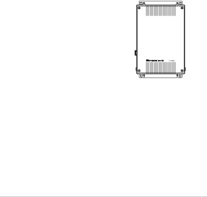
The Strata DK14 Base Key Service Unit (KSU) is a compact system that provides many of the features offered by much larger systems. The Strata DK14 KSU is designed for convenient wall-mounting and occupies very little space (see Figure 1 and Table 1).
At maximum configuration, the Strata DK14 provides up to 10 station ports, that can be used for up to eight digital telephones (including the cordless telephone), up to four Central Office (CO) lines can be accommodated, and two standard telephone devices.
The Strata DK14 can be upgraded with these optional peripherals:
♦Music-on-hold (MOH) source
♦ Background Music (BGM) source
AC 
DC
2186
♦Night bell
♦Amplifier/speaker for external page
Also, any two of the following optional RS-232 interfaces can be added as needed:
♦Caller ID (CLID)
♦Station Message Detail Reporting (SMDR)
♦Simplified Message Desk Interface (SMDI) for Voice Mail
♦DKi Admin (TTY) Interface
Figure 1 Base Key Service Unit
(KSU)
Table 1 |
KSU Specifications |
|
|
|
|
|
|
|
|
|
|
|
|
|
|
Unit |
Weight |
Height |
Width |
Depth |
|
Key Service Base Unit |
5.7 lbs. |
16.4 inches |
10.0 inches |
3.0 inches |
|
|
(2.59 kg) |
(416 mm) |
(254 mm) |
(76 mm) |
||
|
|
|
||||
|
|
|
|
|
|
|
Strata DK General Description 6/00 |
1 |

Strata DK14
KSU Architecture
KSU Architecture
The Strata DK14 KSU contains the main processor, operating software, circuitry and the following components (see Figure 2).
|
HPFB6 |
|
|
|
WARNING |
! |
required,servicingIf A.C.removecord. |
AC |
DC |
voltageHazardousinside |
||||
|
|
|
|
BATT |
|
|
|
DC |
|
J6-25 Pair Amphenol Jack  (female) for
  Telephone Tip/Ring and Relay Contact
|
|
|
|
J2 |
J3 |
J20 |
|
|
|
|
|
|
|
|
|
QRCU3A |
|
|
|
|
|
|
|
Component Side |
|
|
|
||||
|
J1 |
|
J4 |
|
|
|
|
|
J11 |
|
J14 |
|
|
|
|
|
STU |
|
STU |
|
|
|
|
J7 |
J5 |
|
J6 |
J8 |
|
J1 |
J10 |
|
QSTS1A2 |
J1 |
J15 |
|
|
||
|
|
|
|
|
|||
|
|
|
|
|
QKYS |
|
|
|
|
|
QSTU2A |
|
|
|
|
|
190 |
130 |
|
|
J1 |
J9 |
|
|
|
|
|
|
|
||
|
SW1 |
|
|
|
|
||
|
J13 |
|
J12 |
|
|
|
|
|
J3 |
|
|
J2 |
|
|
|
|
STU |
|
STU |
|
|
|
|
VR701
J4
J21
WSIU1A
3 PAD 0 |
SW101 |
QCDU2A
3 PAD 0 |
SW101 |
QCDU2A
J22 |
 SIO 2
SIO 2
 SIO 1
SIO 1
F.G.
CO4
CO2
CO1
F.G.
CO3
PFT, RJ11
Modular
Jack
System
Frame
Ground
Bar
2364
MOH |
600 |
MOH |
Not |
Jack |
ohm |
Volume |
Used |
|
Page |
Control |
|
1 or 2
HPFB reserve power units
6-wire RJ11
Modular Jack
6-wire RJ11
Modular Jacks
Figure 2 |
KSU Interior |
Digital Telephone/Central Office (CO) Line Circuits
The main PCB (WMAU) has four integrated circuits that can connect to digital corded and/or cordless telephones, stand-alone data interface units (PDIU-DSs), and digital door phone/lock control units (DDCB). Each of the digital telephones can support a PC Data Interface Unit (RPCIDI) or up to two Add-on Modules (DADMs). It does not support a DDSS console.
Two circuits for loop start CO lines are built into the main PCB. Each line can be programmed for Dual-tone Multi-frequency (DTMF) or dial pulse signaling. It includes a switch to control potential excess volume from a nearby private branch exchange (PBX) or CO. Built-in gas tubes help protect each circuit from lightning. Each line supports Caller ID when optional equipment is added.
2 |
Strata DK General Description 6/00 |

Strata DK14
Optional Printed Circuit Boards
Optional Printed Circuit Boards
Central Office Line/Digital Telephone Interface Unit (QCDU2)
The QCDU2 provides one loop start CO line circuit and two digital telephone circuits. It interfaces with digital corded and/or cordless telephones, RPCI-DIs, ADMs connected to the corded telephones and PDIU-DSs, and door phones. The DK14 supports up to six door phones. It does not support a DDSS console. Up to two QCDU2 PCBs can be added to the DK14. Each line supports Caller ID when optional equipment is added.
Standard Telephone Interface Unit (QSTU2)
The QSTU2 provides two standard telephone circuits for two-wire devices such as standard telephones, Auto Attendant devices, alternate BGM source connection, voice mail machines, and facsimile machines.
DTMF Receiver/ABR Tone Detector Unit (QRCU3)
The QRCU3 enables the Strata DK14 to recognize Dual-Tone Multi-Frequency (DTMF) tones generated by a standard telephone or any other device connected to a QSTU3 standard telephone circuit. It is also required for Direct Inward System Access (DISA) calls and built-in Auto Attendant. The QRCU3 enables busy tone detection for Automatic Busy Redial.
Auto Attendant Feature Key (QKYS1)
The QKYS1 plugs into the QRCU3 option PCB to support built-in Auto Attendant.
Serial Interface Board (WSIU1)
The WSIU1 provides two serial interface ports for up to two of the following devices:
♦Caller ID interface box
♦SMDR Call Accounting device
♦SMDI Voice Mail Interface
♦PC with DKi Admin or external modem
Strata DK General Description 6/00 |
3 |

Strata DK14
Power Considerations
Power Considerations
The power supply generates +5VDC and +24VDC for the entire system (see Table 2).
Table 2 |
DK14 Electrical Characteristics |
|
|
|
|
||
DK14 Primary Power |
|
||
Input AC |
|
115VAC±10V |
|
AC frequency |
50/60 Hz |
||
Power |
|
46 watts maximum |
|
AC input current |
<0.7 amps. max |
||
|
|
||
Power Supply |
|
||
DC voltage output specification |
+24VDC (+26.3~-27.8VDC) |
||
+5VDC (+4.5~+5.5VDC) |
|||
|
|
||
|
|
|
|
Reserve Power
One or two optional Reserve Power Battery and Chargers (HPFBs) can be connected to the Strata DK14 power supply to maintain normal operation during a power failure. The estimated battery time for one or two HPFBs is shown below.
DK14 (fully-loaded |
Estimated Battery |
system) |
Time (hours) |
One HPFB |
0.5~1.0 |
|
|
Two HPFBs |
1.0~2.0 |
|
|
Notes
●
●
●
Reserve power time varies with system call traffic.
AC power must be available when HPFB is first installed. HPFB recharge time is 48 hours per HPFB.
Power Failure Interface
The Strata DK14 KSU provides an interface for a dedicated backup standard telephone during an AC input power failure. If the system AC input power fails, the backup telephone will automatically connect to the CO1 line. This feature is independent of the HPFB.
Music-on-Hold (MOH) Interface
Customers can connect their own MOH source to this interface. The source can also feed external page speakers and telephone speakers with Background Music (BGM).
Paging Interface
This 600-ohm interface can support a Toshiba External Speaker (HESB) or a customer-supplied amplifier and speaker for Paging, Night Ringing over Page, and BGM applications.
Flexible Relay Contacts
A relay contact can be programmed to either mute BGM during a page announcement over external speakers, to operate a device—such as an answering machine or ringing bell—during the Night Mode, or to provide on-off control for a MOH source.
4 |
Strata DK General Description 6/00 |
Strata DK14
Maximum Line/Station Configurations
Maximum Line/Station Configurations
The maximum line and station configurations for DK14 are shown in Table 3.
Table 3 |
CO Lines and Station Ports |
|
|
|
||
|
|
|
|
|
|
|
|
|
DK14 System |
|
CO Line Ports |
Digital Ports |
Standard |
|
|
|
Telephone Ports1 |
|||
|
|
|
|
|
|
|
|
|
Basic KSU |
|
2 |
4 |
0 or 2 |
|
|
|
|
|
|
|
|
|
Expanded KSU |
|
3 |
6 |
0 or 2 |
|
|
|
|
|
|
|
|
|
Expanded KSU |
|
4 |
8 |
0 or 2 |
|
|
|
|
|
|
|
1. Standard telephone ports do not support MW lamps on standard telephones.
Network Requirements
Network requirements of station/line PCBs and interface cards are summarized in Table 43 on Page 122.
Strata DK General Description 6/00 |
5 |
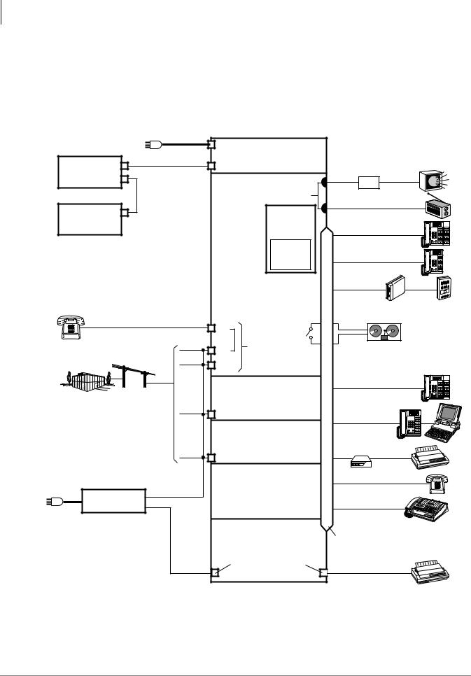
Strata DK14
Functional Block Diagram
Functional Block Diagram
Figure 3 shows the Strata DK14 KSU PCBs and the available lines, stations and peripherals. Basic voltage and cabling information is also included.
115 ± 10VAC (0.7 AMP)
50/60 Hz
DK14 Key Service Unit
HPFB |
|
AC Input |
|
|
|
|
|
QPSU8A2 Power Supply |
|
|
|
||
Battery |
|
|
|
|
||
|
Battery Connector |
|
|
|
||
and Charger |
|
|
|
1 |
||
|
|
|
600Ω |
1 Speaker |
||
(first) |
|
|
|
|
||
|
|
|
|
AMP |
|
|
|
|
|
|
Page |
|
|
HPFB |
|
|
RCA Jacks |
Output |
|
|
|
|
|
MOH/BGM Source |
1 |
||
Battery |
|
|
QRCU3A |
|||
|
|
|
|
|
||
and Charger |
|
|
(optional) |
Digital Telephone |
|
|
(second) |
|
|
DTMF/ABR |
|
||
|
|
|
Receivers (3) |
and Add-on Module |
|
|
|
|
|
|
|
|
|
Note One or two optional HPFB |
|
QKYS1A |
|
|
|
|
|
(optional) |
|
|
|
||
reserve power units may be |
|
Auto |
Digital Telephone |
|
||
|
Attendant |
|
||||
installed. |
|
|
Feature Key |
|
|
|
|
|
|
|
|
|
|
|
|
KSU Main Circuit Board |
DDCB |
MDFB |
||
|
|
(standard) |
||||
|
|
|
|
|
||
Power Failure |
|
4 — Digital Telephone CKTS |
|
|
|
|
|
2 — Loop CO Line CKTS |
Door Phones and Lock Control |
||||
Telephone 1 |
|
|
|
|
|
|
|
|
PFT |
Relay |
|
1 |
|
|
|
Contact |
|
|
|
|
|
|
Line 1 |
X |
|
|
|
Loop Start Lines |
|
RJ11C |
Night Bell, BGM Mute, or |
|||
• FIC: 02LS2 |
RJ11C/ |
CO1 |
Modular Jack |
MOH (Control Relay) |
|
|
Line 2 |
|
|||||
• REN: 0.3 B |
RJ21X |
|
|
|
|
|
|
|
CO2 |
|
|
|
|
|
|
QCDU2A (first/optional) |
Digital Telephone |
|
||
|
|
and Add-on Module |
|
|||
|
|
2 — Digital Telephone CKTS |
|
|
|
|
Central Office/ |
|
1 — |
Loop CO Line CKT |
|
|
1 |
Centrex/PBX |
|
Line 3 |
|
Digital Telephone |
||
|
|
|
|
|||
|
|
CO3, RJ11C |
With RPCI |
|
|
|
|
|
|
|
|
|
|
|
|
QCDU2A (second/optional) |
|
|
|
|
|
|
2 — Digital Telephone CKTS |
|
|
|
|
|
|
1 — |
Loop CO Line CKT |
Stand-alone |
|
1 |
|
|
Line 4 |
|
Data Interface |
|
|
|
|
|
|
|
||
|
|
CO4, RJ11C |
|
|
|
|
|
DIU |
Shared |
|
|
|
|
|
QSTU2A (optional) |
|
Printer |
1 |
2 — Standard |
|
|
|
Telephone CKTS |
Standard Telephone |
|
|
RJ14C |
|
|
|
Caller ID Interface |
|
FAX |
1 |
1 |
|
||
Box (TC-1041) |
|
|
|
117 VAC |
|
|
|
WSIU (optional) |
|
|
|
DKi Admin, SMDR, SMDI |
25-pair Amphenol Connector |
|
|
or CLID Interface CKT |
|
||
|
|
|
|
|
3-pair Modular Interface |
1 |
|
RS-232 Port 2 |
|
|
|
|
RS-232 Port 1 |
|
SMDR |
|
Printer |
|
|
|
2419
1. Customer-supplied equipment
Figure 3 Functional Block Diagram
6 |
Strata DK General Description 6/00 |

Strata DK14
System Technology
System Technology
Pulse Code Modulation
Digital switching talkpaths enable all CO and intercom lines to be accessed simultaneously. Analog-to-digital and digital-to-analog conversion is done by CODECs (coder plus decoder) on station and CO line PCBs.
Custom Electronic Circuitry
Large Scale Integration (LSI) technology makes the Strata DK14 circuit designs simple and efficient. Gate arrays using very large scale integration save vast amounts of space by using the latest technology. More circuitry fits onto smaller PCBs for a more compact system. Widespread use of CMOS circuits minimizes system power requirements.
Stored Program Control
The system uses a 16-bit microprocessor for stored program control. The Strata DK14 System operating software is stored on Read Only Memory (ROM), and individual configuration and custom programming is stored on Random Access Memory (RAM). A lithium battery with a life span of at least six years preserves RAM in the case of a power failure.
Microprocessors
The system’s main microprocessor is a 16-bit 68000-type that operates at a clock speed of
8 MHz. In addition, some PCBs use 8-bit, TMP90C840-type local microprocessors that run at 10 MHz. This distributed microprocessing architecture is used system wide.
Strata DK General Description 6/00 |
7 |

Strata DK14
Maintenance and Programming
Maintenance and Programming
Hardware maintenance and repair procedures describe how to quickly locate, remove, and replace defective parts and PCBs. System programming can be performed without taking the system out- of-service.
On-site programming can be executed with any 20-button proprietary LCD telephone or with a DKi Admin PC connected to an optional maintenance port.
Off-site programming with DKi Admin, which can help cut costs and save time, is available through a customer-provided modem connected to the maintenance port.
DKi Admin/DKi Backup
Toshiba DKi Admin Release 4.0 software enables customer data (configuration, station, and system options) to be downloaded to a PC and stored on a computer disk. The customer data can be added to, or changed, using the PC independent of the DK System.
The new customer data can then be uploaded to the DK System from the PC, changing customer program options on-site or remotely over telephone lines and/or modems.
The DKi Backup software program is also available. The program consists of a small subset of DKi Admin functions which can perform backup, restore and upgrade functions, but cannot edit customer databases.
8 |
Strata DK General Description 6/00 |
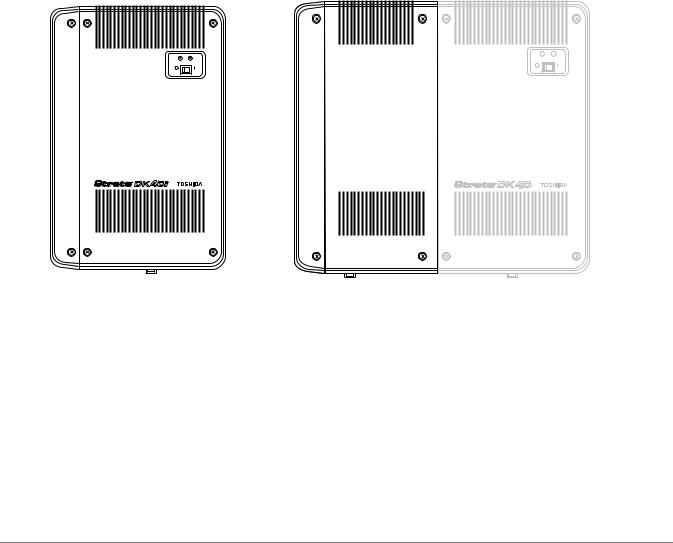
Strata DK40i |
2 |
|
|
This chapter provides an overview of the Strata DK40i Release 4.3 system and its capacities. Release 4.3 enables the DK40i to provide Automatic Call Distribution (ACD), E911 CAMA, T1, ISDN PRI and BRI U and S/T interfaces.
The Strata DK40i Base Key Service Unit (KSU) is a compact system that provides many of the features offered by much larger systems. The KSU is designed for convenient wall-mounting and occupies very little space (see Figures 4, 5 and Table 4.)
|
AC |
DC |
AC |
DC |
POWER |
|
POWER |
|
4247
1711
Figure 4 |
Base Key Service Unit (KSU) |
Figure 5 |
KSU with Expansion Unit |
|
||||
Table 4 |
KSU and Expansion Unit Specifications |
|
|
|
|
|||
|
|
|
|
|
|
|
|
|
|
Unit |
Weight |
|
|
Height |
Width |
|
Depth |
|
Key Service Base Unit |
8.4 lbs. |
|
18.0 inches |
12.2 inches |
|
3.4 inches |
|
|
(3.8 kg) |
|
(457 mm) |
(310 mm) |
|
(86 mm) |
||
|
|
|
|
|||||
|
|
|
|
|
|
|
|
|
|
|
1 lb. empty |
|
|
|
|
|
|
|
Expansion Unit |
(0.45 kg) |
|
18.0 inches |
7.8 inches |
|
3.4 inches |
|
|
4.3 lbs. full |
|
(457 mm) |
(198 mm) |
|
(86 mm) |
||
|
|
|
|
|||||
|
|
(2.4 kg) |
|
|
|
|
|
|
|
|
|
|
|
|
|
|
|
Strata DK General Description 6/00 |
9 |
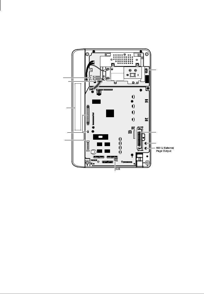
Strata DK40i
Base KSU Architecture
Base KSU Architecture
The Strata DK40i Base KSU contains the main processor, operating software, circuitry and the following components (see Figure 6).
1 2 PN2
POWER SUPPLY ASSEMBLY
MODEL TPSU16A
INPUT: AC127V 2.2A 60 HZ
OUTPUT: -27.3V 2.8A. -27.3V 0.2A |
AC |
V. 1A 1996-05 00001 |
|
TOSHIBA CORPORATION |
DC POWER |
MADE IN |
-24 Volt Circuit |
WARNING |
Breakers |
Hazardous voltage inside! |
If servicing required |
|
|
remove A. C. plug. |
Connect Expansion |
|
|
|
Unit TB1 TO FG2 |
|
|
FG2 |
|
is required for expansion |
|
|
|
with this unit |
|
|
Important Notice |
DKSUE16A is incompatible |
DKSUET16A or DKSUE40A |
|
|
|
||
Expansion KSU |
IMPORTANT: |
|
TMAU2A |
|
OFF |
||
Cable Receptacle |
|
||
|
ON |
|
Battery Jumper
2 |
+ |
|
Reserve Power |
DC |
|
BATT |
|
-1 |
Battery Jack |
||
Base Telephone |
Tip/Ring and |
Relay Contact |
Music-on-Hold |
Input |
4238
Music-on-Hold
Sensitivity Adjustment
Figure 6 Base KSU Interior
Digital Telephone Circuits
The main circuit board (TMAU2) in the Strata DK40i Base KSU has eight integrated circuits that can connect to Toshiba-proprietary digital telephones (including the cordless telephone), Standalone Data Interface Units (PDIU-DSs), Digital Door Phone/Lock Control Units (DDCB), and Digital Direct Station Selection Consoles (DDSS).
Furthermore, each of the digital telephones can support a PC Data Interface Unit (RPCI-DI) or up to two Add-on Modules (DADMs).
Central Office (CO) Line Circuits (TCOU/TDDU/TBSU/TBUU)
The following PCBs can be installed in the DK40i Base KSU:
♦TCOU provides four circuits for loop start CO lines.
♦TDDU provides four circuits for Direct Inward Dialing (DID) lines
♦TBSU provides two circuits for BRI lines or stations (see TBSU below)
♦TBUU provides two BRI U interface circuits for lines or stations
10 |
Strata DK General Description 6/00 |

Strata DK40i
Base KSU Architecture
The CO line interface and DID interface unit can be programmed for DTMF or dial pulse signaling and each line has a switch to control potential excess volume that could be created by a nearby PBX or CO. Built-in gas tubes help protect each TDDU and TCOU line from lightning. An optional RDDU (for DID lines) installed in the Expansion Unit requires an external secondary protector. DID lines require the optional K5RCU2 tone receiver.
ISDN BRI S/T Circuits (TBSU)
The TBSU PCB provides two Basic Rate Interface (BRI) circuits for DK40i. The TBSU can only be installed in the DK40i Base KSU.
The TBSU circuits are four-wire S/T type circuits and connect to the PSTN BRI lines using a dealer-supplied UL-listed Network Terminator unit (NT1). In Canada, the NT-1 must be CSA certified. On the station side, they can connect to S-type ISDN Terminal Equipment (TE) or Terminal Adapters (TA).
ISDN BRI U Circuits (TBUU)
DK BRI U interface circuits can be configured to connect to an ISDN line circuit (NT mode, lineside) or to ISDN U-type terminal equipment TE1 or terminal adapters TA (LT mode, station side). The TBUU provides two BRI-U circuits that can be configured independently for line or station circuits.
Note The TBSU and TBUU contains two circuits, each of which reduces the system capacity by two station ports or two CO lines. If the BRI circuit is configured as a station circuit, the circuit assumes two station ports. If the BRI circuit is configured as a line circuit, the circuit assumes two CO lines. BRI lines can be used for voice and data calls.
Caller ID (TCIU2)
An optional Caller ID PCB (TCIU2) can be added to the four-circuit loop start CO line PCB (TCOU) to provide four Caller ID circuits. Local telephone companies do not provide Caller ID on DID lines; so the TCIU2 PCB cannot be added to the four-circuit DID PCB (TDDU). Caller ID can also be added with the RCIU2 and KCDU2. See “Caller ID Interface Unit (RCIU2)” on Page 41 and “Caller ID” on Page 69 for more information.
Standard Telephone Interface Unit (KSTU2)
The optional KSTU2 provides four circuits that can interface with DTMF for rotary dial standard telephones and other single-line devices, including: Strata AirLink Wireless Base Station Interface Adapters (BSIAs) and handsets, fax/modems (14.4 bps max.), Voice Mail and Auto Attendant devices, off-premises stations, alternate BGM source and dictation equipment. These devices may require that the optional tone receiver (K5RCU or K5RCU2) be installed in the DK40i Base KSU to interpret the DTMF signals the above devices may transmit.
The KSTU2 does not support message waiting lamps on standard telephones. The RSTU2 must be installed in the Expansion Unit to support message waiting lamps.
DTMF/ABR Tone Detection Receiver (K5RCU and K5RCU2)
Station users in systems that have the optional K5RCU or K5RCU2 installed can access Automatic Busy Redial (ABR) and communicate with devices, such as standard telephones or voice mail machines that require DTMF signaling.
This unit is also required for Direct Inward System Access (DISA) and built-in or external Auto Attendant operation, as well as for DID and Tie lines. Each K5RCU or K5RCU2 PCB contains five shared receivers.
Strata DK General Description 6/00 |
11 |
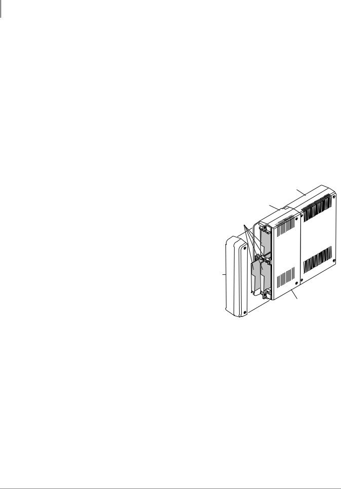
Strata DK40i
Expansion KSU Architecture
Feature Key (KKYS)
The system can be upgraded with an optional feature key, the KKYS, which installs onto the K5RCU PCB in the Base KSU. The KKYS1 provides Automated Attendant (AA); KKYS2 provides AA and ACD; and KKYS3 provides AA and ACD/MIS.
SMDR, SMDI, ACD/MIS and Maintenance DKi Admin/Modem (TTY) Interface (TSIU)
The TSIU PCB provides two RS-232 interface ports (modular jacks) that allow the DK40i system to connect to an SMDR Call Accounting device, a DKi Admin PC or external modem for system maintenance/administration, ACD/MIS reports using Toshiba’s Insight DK software, or an SMDI interface for Voice Mail. It does not have a built-in modem capability.
Only one TSIU can be installed per DK40i system. When the TSIU PCB is installed, the PIOU can still be installed for zone paging, control relays, and an SMDR RS-232 interface, built-in (IMDU) maintenance modem, ACD/MIS processor or VM SMDI or maintenance interface.
Expansion KSU Architecture
The optional Expansion KSU, which attaches easily to the side of the Base KSU, offers four universal slots that can host a variety of line and telephone PCBs (see Figure 7). See Chapter 4 – Universal Slot PCBs for descriptions of PCBs.
Station and Line Capacities
Strata DK40i
Base KSU
Strata DK40i
Expansion KSU
Expansion
PCB Slots
Side
Cover
Expansion Cover
4243
Figure 7 Expansion KSU Interior
This section shows the maximum basic and CO configurations that are possible with the DK40i. There is a variety of configuration combinations of digital and standard telephones with CO lines, including loop start, ground start, Tie, and DID lines. Any loop or ground start CO line can be equipped with Caller ID.
The DK40i Base KSU comes equipped with eight digital telephone station circuits. One of four optional PCBs can be added to provide either four loop start or DID lines, or two ISDN BRI S/T or U circuits. Another optional TCIU2 PCB can be added to the Base KSU loop start line PCB to provide Caller ID interface. An optional KSTU2 PCB can be added to provide four standard telephone circuits (ports).
An optional Expansion KSU can be added to the DK40i to increase the system capacity to 28 station ports and 12 CO lines (see Figure 5). A maximum of 28 station ports and 12 CO line interfaces are allowed in the system (Base KSU plus Expansion KSU). Base capacity is 12 station ports and 4 CO line or 2 BRI circuit interfaces.
12 |
Strata DK General Description 6/00 |

Strata DK40i
Station and Line Capacities
Table 5 shows maximum capacity for a DK40i system. DKi Quote, an auto quote program that runs on a PC with Microsoft® Windows® , is available from Toshiba to generate DK40i quotes and configurations. Also, refer to the Strata DK Installation and Maintenance (I&M) Manual,
Chapter 2 – DK40i Configuration, for more information.
Table 5 Maximum CO Lines/Ports and BRI Line and Station Circuits
Hardware |
Maximum |
|
Allowed |
||
|
||
CO Lines |
12 |
|
|
|
|
Station Ports |
28 |
|
|
|
|
BRI Line Circuits |
6 |
|
|
|
|
BRI Station Circuits |
10 |
|
|
|
Attaining maximum system capacities depends on power consumption of a particular configuration (see Table 6). Power factor calculations in accordance with the Strata DK I&M Manual will determine if the maximum capacities in these tables can be reached.
Table 6 |
DK40i Station and Line Capacities and Universal Printed Circuit Board Slots |
|
|
|
|
|
Lines and PCB Slots |
DK40i |
|
Universal slots1 |
41 |
|
Stations2 |
8~282 |
|
CO lines – loop start |
0, 2, 4, 8 or 123 |
|
CO lines – ground start |
0, 2, 4, 8 or 123 |
|
DID lines (analog)4 |
0, 2, 4, 8 or 123 |
|
Tie lines (analog)3 |
0, 2, 4, 8 or 123 |
|
T1 lines |
8 or 12 channels/lines |
|
|
|
|
ISDN BRI line circuits (S/T type and/or U type)5 |
2, 4 or 6 circuits (12 B-channels/lines)3 |
|
ISDN PRI line circuits |
8 or 12 channels/lines |
|
|
|
|
Squared System Maximum (ground/loop lines + stations) |
12 lines + 12 stations |
|
|
|
|
Squared System Maximum (Tie/DID lines + stations) |
12 lines + 12 stations |
|
|
|
1.There are four universal slots in the DK40i expansion unit.
2.Line and station capacities cannot exceed 28 stations and/or 12 CO lines. Incremental capacities depend on the type of station/line PCBs installed. All increments are not available with all PCB types.
3.Increments vary and depend on the type of line PCBs installed.
4.In the D40i, DID and Tie, lines do not use up station ports as in DK40, R3.1 and the DK424 R3.2. Each BRI line circuit uses up to two CO lines of system capacity and no station ports.
5.Each S/T type circuit requires an NT-1 device when connected to a Central Office BRI line circuit.
The DK40i Base and Expansion cabinets provide an extensive number of features for a telephone system of its size. See Table 40 on Page 109 for a list of DK40i, Release 4.3 features and capacities.
ISDN BRI Lines
Stations can be a combination of ISDN TE-1 and TA S-type devices and digital, electronic or standard telephones. CO line combinations include ground or loop start, DID, Tie or ISDN BRI. Each BRI line circuit uses up two CO lines at system capacity. All other line circuits use up one CO line of system capacity.
Each BRI station circuit uses up to two station ports of system capacity. All other station circuits use up one station port of system capacity.
Strata DK General Description 6/00 |
13 |

Strata DK40i
Peripherals
Table 7 Typical Maximum Capacity Examples with ISDN BRI (S/T and/or U-type) Circuits
BRI Station |
Other Station |
BRI Line |
BRI Line |
Other Line |
Circuits1 |
Circuits3 |
Circuits4 |
B channels |
Circuits5 |
102 |
8 |
6 |
12 |
0 |
8 |
12 |
4 |
8 |
4 |
|
|
|
|
|
6 |
16 |
4 |
8 |
4 |
|
|
|
|
|
4 |
20 |
6 |
12 |
0 |
|
|
|
|
|
4 |
20 |
4 |
8 |
4 |
|
|
|
|
|
2 |
24 |
2 |
4 |
8 |
|
|
|
|
|
0 |
28 |
0 |
0 |
12 |
|
|
|
|
|
1.Each BRI circuit (S/T and/or U-type) provides two B channels plus one D channel. Each (S/T) BRI station circuit allows up to two TE-1 and TA devices to share the BRI B channels (two simultaneous calls maximum per BRI circuit.). Each BRI-U circuit supports one TE-1 or TA device.
2.Maximum BRI line capacity. BRI station circuits do not use up CO line channels and vice versa. Also, station circuits use 2B + 1D channel; lines use one B channel which enables one BRI circuit to provide two lines.
3.Other stations include Toshiba digital and electronic telephones, or attendant consoles, standard telephones and devices.
4.BRI S/T circuits are available with TBSU and RBSU/RBSS PCBs and BRI-U circuits are available with TBUU and RBUU/RBUS PCBs. Each BRI line circuit (S/T or U) provides two BRI CO lines (B channels) for incoming/outgoing calls.
5.Other lines include analog and digital (T1 or PRI) loop start, ground start, DID, and Tie lines.
Peripherals
The DK40i Base KSU can support a number of peripherals, which are not considered as stations or lines and do not affect the maximum station and line capacities. The DK40i Base KSU comes standard with built-in interfaces for connecting the following dealer-supplied equipment: an amplifier and speaker for paging and night ringing, Music-on-Hold (MOH) source, reserve power batteries, and emergency standard telephone for system power failure occurrences when using loop start lines in the base cabinet.
A relay contact is also provided to control one of the following peripherals: MOH source, night bell, or page amplifier mute control.
An optional KSTU2 PCB provides an alternate background music source interface. The music plays through Toshiba telephone speakers, as opposed to the external page speakers.
The optional TSIU PCB provides two RS-232 interface ports to connect two of four options: a DKi Admin PC (or external modem for remote maintenance); or VM SMDI, ACD/MIS or an SMDR port to connect a call accounting device or printer. An Expansion Unit RS-232 interface PCB is required if all four features are needed.
14 |
Strata DK General Description 6/00 |
Loading...