

Page 1

- Data Brochure
R
D 269
One Stage Steam Control 269
The tekmar One Stage Steam Control 269 is a microprocessor-based control which regulates the
firing time of a steam boiler based on user settings, outdoor air temperature, condensate return
temperature, and optionally, the indoor air temperature(s). The steam boiler can be operated in
the outdoor reset mode, or in Manual Override mode based on dial settings. The control has builtin diagnostics for sensor checking with a Warning output for error reporting. Other control
operation features include Auxiliary relay output, Steam Established and Lockout Differential
temperatures, and Early Start with setback limit when using the Unoccupied input.
70°F
70°F
(21°C)
(21°C)
40
40
100
(4)
(4)
(38)
Occupied
Unoccupied
One Stage Steam Control 259
with Early Start
Steam
Power
established
Heating
WWSD
cycle
Early Start
UnOcc.
Auxiliary
Warning
100
(38)
Boiler
R
R
LR 58233
E150539
Outdoor Reset Strategy . . pg. 2
Sequence of Operation . . . pg. 3
Installation . . . . . . . . . . . . . pg. 6
Settings . . . . . . . . . . . . . . . pg. 8
Early Start
into or
out of UnOcc.
System is in
Warm Weather
Shut Down
System is in
Unoccupied
mode
Sensor Fault
warning
Occupied
temperature
setting
Unoccupied
temperature
setting
Boiler is on
120Vac power
supply is on
70°F
(21°C)
40
100
(4)
(38)
Occupied
One Stage Steam Control 269
with Early Start
Use Nº 20 AWG or larger copper conductors rated for at least 75°C and 300V.
Heating Cycle
is in progress
70°F
(21°C)
40
100
(4)
(38)
Unoccupied
1234 5
Power
Warn.
NL
Aux.
Condensate
temperature is
established
6
Power
WWSD
UnOcc.
Warning
LR 58223
78
Boiler
Auxiliary relay
output is on
Steam
Established
Heating
Cycle
Early Start
Auxiliary
Boiler
Listed
R
5T62
R
E150539
Testing . . . . . . . . . . pg. 9
Error Messages . . . pg. 11
Technical Data . . . . pg. 12
Limited Warranty . . pg. 12
Operating Mode
selector switches
Indoor Sensor S1
Indoor Sensor S2
Early Start
45%
0
Auto
100
Man. Override
Test
Manufactured
in Canada by
Power: 120V 50/60Hz 3VA
Relays: 120Vac 10A 1/4 hp 240VA, 2A pilot duty
Enclosed Energy Management Equipment
9
10K
S1
Condensate Return Sensor
123 4
Off
0 °F
10
180 °F
Steam
11 12
UnO
Sw
1
40
Cycle Length
5
Off2550
Min. On Time (%)
Lockout Diff'l (°F)
13 14 15
Com
10K
Sen
S2
2093
1234567
Cnd Out
Sen
-40
Design Out
130 230
Established
Do not apply power here
10
Com
Sen
50 min
R
06/00
Manual
override setting
System design
outdoor
temperature
setting
Heating cycle
length setting
Steam
established
100
(condensate
temperature)
setting
Minimum on
time/lockout
differential
Date
S/N
setting
Test button and
LED to test main
control functions
H1099
Sen
Terminal Plugs:
Power and out-
put connections
120 Vac
power supply
Warning Relay
Output:
Output:
Auxiliary Relay
Output:
Turn on boiler
Input: Indoor
Sensor 074
Optional
Input:
Unoccupied
signal
Optional
Input: Outdoor
Sensor 070. Included
Input: Condensate
Return Sensor 071.
Included
Input: Indoor
Sensor 074
Copyright © D 269 - 06/001 of 12
Optional
Page 2
Outdoor Reset Strategy
Boiler
off
15 minutes
off time
15 minutes
off
on time
Boiler Operation
Boiler
on
30 minute cycle
Figure 1. 50% on time with a 30 minute heating cycle
Boiler on
off
Boiler Operation
30 minutes
on time
60 minute cycle
Figure 2. 50% on time with a 60 minute heating cycle
Boiler is turned off
WWSD
Point
90
70
(32)
(21)
Boiler is cycled on/off
Design
Outdoor
Temperature
50
(10)
Outdoor air temperature
30
(-1)10(-12)
-10°F
(-23)°C
Figure 3. Outdoor Reset of boiler % on time
on
15 minutes
on time
30 minute cycle 30 minute cycle 30 minute cycle
off
15 minutes
off time
on
15 minutes
on time
off
15 minutes
off time
on
15 minutes
on time
Boiler off
30 minutes
off time
on
30 minutes
on time
off
30 minutes
60 minute cycle
100%
90%
80%
70%
60%
50%
40%
30%
Boiler is turned on 100%
20%
10%
0%
on time
-30°F
(-34)°C
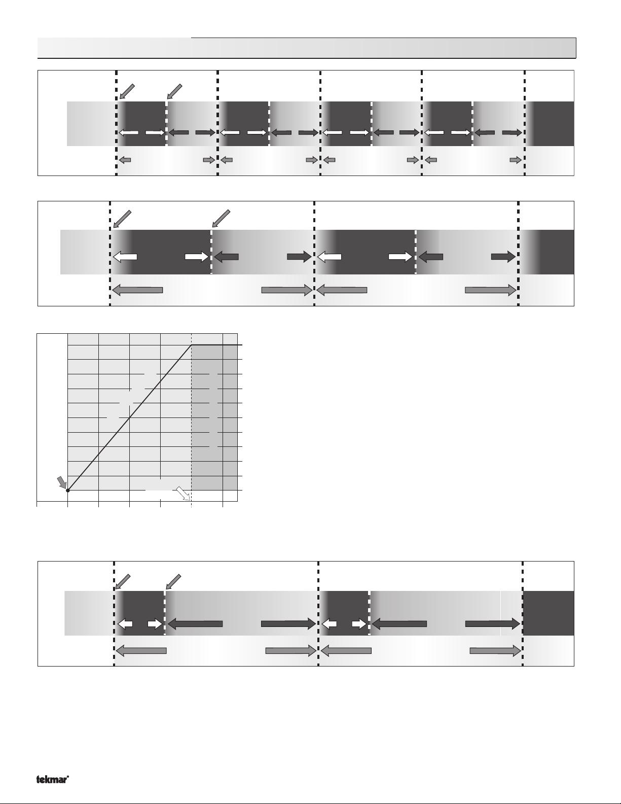
Most residential and small commercial steam systems can only produce
heat at a fixed rate and are either on (100% output), or off (0% output). When
100% output is not required (warmer weather), the boiler must be cycled on
and off in order to prevent overheating. Figures 1 and 2 illustrate the
operation of two heating systems with different heating cycle times.
Cycle times are selected based on the operating characteristics of each
individual heating system. Figure 1 shows a system where a 30 minute cycle
is required, and Figure 2 shows a system where a 60 minute cycle is required.
In both examples the heating plant output is exactly the same at 50%.
As the outdoor temperature changes, the % on time of the boiler should
be changed to match the changing heat losses of the building. Figure 3
illustrates how Outdoor Reset of a steam boiler changes the % on time from
Percentage of boiler on time per cycle
0% at the Warm Weather Shut Down point, to 100% at design outdoor
conditions (coldest day of the year). Applying this chart to the system
represented in Figure 1, we see that the outdoor temperature would be at
30°F with the 50% on time that is illustrated, and if the outdoor temperature
warmed up to 50°F, the system would operate with a 25% on time as
illustrated in Figure 4. Using outdoor temperature to reset the % on time in
this manner can help minimize the overheating and wide temperature swings
found in many systems that use only room temperature control.
off time
off
15 minutes
off time
on
on
Boiler
off
45 minutes off time
60 minute cycle
on
15 minutes
on time
off
45 minutes off time
60 minute cycle
on
15 minutes
off
on time
Boiler Operation
Boiler
on
Figure 4. 25% on time with a 60 minute cycle time
Before adding this control to a steam system, it is very important that the installer examine the
complete
system and how
it works. In order to properly install and setup this control, the installer must know: the optimum cycle length and minimum on
time of the system, the outdoor temperature at which 100% boiler on time will be required, and the best locations to install
sensors. In addition to examining the boiler operation,
all other
system components such as steam traps, air vents, radiators,
piping, etc. should be examined for correct operation to ensure that the system is working at its peak efficiency. If there are
existing faults that degrade the operation of the system, it is quite likely that the addition of this control could allow those faults
to have an even greater effect, making it important to correct such faults or at least point them out to the end user.
Copyright © D 269 - 06/00 2 of 12
Page 3

Sequence of Operation
Start-up
When the One Stage Steam Control 269 is powered-up, the "Power" light and all of the red
lights will come on. After 5 seconds the red lights will go out and the control will enter the
operating mode. If there is a sensor error detected, the control will display an error message
(see "Error Messages", page 11).
Power
WWSD
UnOcc.
Warning
Manual Override function
If the "Man. Override" dial is turned up from the "Auto" position, the WWSD, Heating Cycle, Early
Start and UnOcc. lights will cycle on and off in a clockwise, circular sequence and the control
will continually operate the system at the % on time setting of the "Man. Override" dial position.
Power
WWSD
UnOcc.
In this mode, the only two dial adjustments that will have any influence on the control's operation
will be the "Man. Override" and the "Cycle Length" dials, and the control will cycle the boiler on
Warning
and off as illustrated in Figures 1, 2 and 4 on page 2. Outdoor or room temperatures will have
no effect on the operation of the control when it is in "Man. Override" mode.
Auto (reset) function
If the "Man. Override" dial is set to the "Auto" (Outdoor Reset) operating mode, the control uses the Outdoor Sensor 070 to
continually monitor the outdoor temperature. As options, a Condensate Return Sensor 071 can continually monitor the temperature
of the condensate return line and one or two Indoor Sensors 074 can continually monitor the indoor air temperature. DIP switches
for Condensate Return Sensor and Indoor sensors must be switched on when these sensors are connected.
An Error Message
will be displayed if these switches are in the on position without sensors installed.
While monitoring all of these temperatures, the control recognizes the following inputs and will respond as described. During
operation, the lights of the control will indicate operational status as illustrated.
Outdoor Sensor 070 only
When an Outdoor Sensor 070 is connected to the control and the
"Design Out" dial set to the correct setting, the control will cycle
the boiler on and off based on the outdoor temperature and the
settings on the "Cycle Length" and "Min. On Time (%)" dials as
shown in Figure 5.
The "Min. on time (%)" dial must be set to at
least the minimum time required for the boiler to produce steam
and add heat to the building.
As soon as the outdoor temperature
drops below the setting of the "Occupied" dial (WWSD point), the
"WWSD" light will go out and the "Heating Cycle" and "Auxiliary"
lights will come on. The "Boiler" light will come on and the
123 4
Off
Power
WWSD
UnOcc.
Warning
Indoor Sensor S1
Indoor Sensor S2
Condensate Return Sensor
Steam
established
Heating
cycle
Early Start
Auxiliary
Boiler
123 4
Off
Power
WWSD
UnOcc.
Warning
Indoor Sensor S1
Indoor Sensor S2
Condensate Return Sensor
Steam
established
Heating
cycle
Early Start
Auxiliary
Boiler
Condensate return sensor,
+ Indoor sensors S1 & S2
DIP switches = off
boiler will fire for at least the time set on the "Min. On Time (%)" dial, and then shut off for the remainder of the time set on the "Cycle
length" dial. This cycle will be repeated until the outdoor temperature becomes warmer than the "Occupied" dial setting, putting the
control back into WWSD. Adjusting the "Occupied" dial shifts the WWSD point and heating curve up or down as shown in Figure
6, and the indoor air temperature will be affected accordingly. The "UnOccupied" dial works the same way as the "Occupied" dial
when the control has been put into the UnOccupied mode, except the design outdoor temperature is also shifted down.
Indoor Sensor 074 function
When Indoor Sensor 074s are connected to this control, the control will still operate the boilers based on
outdoor temperature, but will also use one 074 sensor input, or the lower reading of two 074s to prevent
overheating. With these sensors, the "Occupied" and "UnOccupied" dial settings become the desired
indoor air temperatures.
The control will not allow the curve to be shifted up,
if windows or doors are left
open. Figure 7 shows how an Indoor Sensor will shift the heating curve and the WWSD point down to
prevent overheating, especially in milder weather when a Minimum On Time may cause overheating.
Boiler is cycled on/off
Boiler is turned off
Boiler is turned on 100%
-10°F
-30°F
(-23)°C
(-34)°C
90
(32)
WWSD
Point
70
(21)
(10)30(-1)10(-12)
20% minimum on time
50
Design
Outdoor
Temperature
Outdoor air temperature
Figure 5. Outdoor Reset with a
20% Minimum On Time setting
100%
90%
80%
70%
60%
50%
40%
30%
20%
20% Min. on time selected
10%
Percentage of boiler on time per cycle
0%
on time
Boiler is turned off
WWSD
Point
90
(32)
(21)
Figure 6. Shifting the heating curve
Boiler is cycled on/off
20% minimum on time
Design
Outdoor
70
Temperature
50
(10)30(-1)10(-12)
Outdoor air temperature
-10°F
(-23)°C
with the Occupied dial
100%
90%
80%
70%
60%
50%
40%
30%
Boiler is turned on 100%
20%
20% Min. on time selected
10%
Percentage of boiler on time per cycle
0%
on time
-30°F
(-34)°C
WWSD
90
(32)
Figure 7. Temporary shift to UnOc-
cupied mode or by Indoor Sensor
If the indoor temp. becomes
too warm, the Heating
Curve shifts down.
After the Heating
Cycle, the boiler is
kept off until the
indoor cools off
to the desired
room temp.
Boiler is turned off
Point
70
(21)
Early Start
123 4
Early Start
123 4
Indoor sensors S1 or
S1 & S2 DIP switches = on
Boiler is cycled on/off
20% minimum on time
Design
Outdoor
Temperature
50
(10)30(-1)10(-12)
Outdoor air temperature
Off
Off
-10°F
(-23)°C
074 room temperature feedback
Copyright © D 269 - 06/003 of 12
Steam
established
Heating
cycle
Early Start
Auxiliary
Boiler
Steam
established
Heating
cycle
Early Start
Auxiliary
Boiler
Power
WWSD
UnOcc.
Warning
Indoor Sensor S1
Indoor Sensor S2
Condensate Return Sensor
Indoor Sensor S1
Indoor Sensor S2
Condensate Return Sensor
Boiler is turned on 100%
-30°F
(-34)°C
Steam
established
Heating
cycle
Early Start
Auxiliary
Boiler
100%
90%
80%
70%
60%
50%
40%
30%
20%
20% Min. on time selected
10%
Percentage of boiler on time per cycle
0%
on time
Page 4

Condensate Return Sensor 071 function
Ind
S2
Setting a Minimum On Time for a steam system can
become problematic because a system takes more time to
reach operating temperature from a cold start than when it
is hot from a previous cycle. Use of the Condensate Return
Sensor included with the control is highly recommended
since the "Steam Established" dial can then be set to match
the operating characteristics of the system. The control will
turn on its "Boiler" light and fire the boiler for a warm-up
period, modifying the cycle to operate as in Figure 8.
Early Start
Establishing Steam
(Warm up)
Power
WWSD
UnOcc.
Warning
Steam
established
Heating
cycle
Early Start
Auxiliary
Boiler
123 4
Off
oor Sensor
Condensate Return Sensor
Heating Cycle
(on time)
Steam
Power
established
Heating
WWSD
cycle
Early Start
UnOcc.
Auxiliary
Warning
Boiler
Condensate return sensor
DIP switch = on
Steam
Power
established
Heating
WWSD
cycle
Early Start
UnOcc.
Auxiliary
Warning
Boiler
Heating Cycle
(off time)
Steam
Power
established
Heating
WWSD
cycle
Early Start
UnOcc.
Auxiliary
Warning
Boiler
Boiler on
off
Boiler Operation
15 minutes
on time
Boiler off
Steam established - start cycle
45 minutes off time
60 minute cycle
Boiler on
15 minutes
on time
Steam established - start cycle
45 minutes off time
60 minute cycle
Boiler off
220°F
210°F
200°F
190°F
180°F
(Warm-up period)
Establishing Steam
170°F
temperature
160°F
Condensate return
150°F
est.
off
Steam established
temperature setting
(Warm-up period)
Establishing Steam
est.
on
off
140°F
on
Figure 8. 25% on time with Condensate Return Sensor and "Steam Established" dial set to 170°F
The control will not start to time out the Heating Cycle until the Condensate Return Sensor reaches the temperature set on the "Steam
Established" dial. When this occurs, the "Steam Established" light will come on and the control will operate the boiler until the on time of the
Heating Cycle has elapsed. This function ensures that steam has been established throughout the system before the Heating Cycle is started.
In a two pipe system, most installers will place the Condensate Sensor on the condensate return line of the radiator furthest from the boiler.
In one pipe systems the best location is usually on the pipe just before it enters the last radiator. These locations are usually good, but in
some larger systems with long runs it may be necessary to place the sensor closer to the boiler so that the first rooms in the system do not
overheat. Again, it is important to ensure that the system components are all working properly, since in a properly vented and drained system,
steam is established quickly throughout the system during each cycle, and sensor placement is not as critical as in some "problem" systems.
Boiler on
15 minutes
on time
Boiler off
Steam established - start cycle
45 minutes off time
Boiler on
15 minutes
on time
Steam established - start cycle
45 minutes off time
Boiler off
Boiler
Operation
60 minute cycle
220°F
210°F
200°F
190°F
180°F
170°F
160°F
temperature
150°F
Condensate return
140°F
Figure 9. 25% on time with Condensate Return Sensor, "Steam Established" dial set to 170°F and "Lockout Diff'l" set to 30°F
Copyright © D 269 - 06/00 4 of 12
off
Steam established
temperature setting
30°F Lockout differential setting
Lockout period
(Warm-up period)
Establishing Steam
est.
on
60 minute cycle
off
Lockout period
on
(Warm-up period)
Establishing Steam
Page 5

Lockout Differential function
Many steam systems require a Lockout (cool
down) period before each on cycle to ensure
that any remaining steam in the system
condenses and the condensate has time to
return to the boiler. This increases the efficiency of the system by removing the latent
heat from steam remaining after the burner
shutdown, and lengthening the cycle so that
the remaining heat is allowed to radiate into
the building. When using a Condensate Sen-
Establishing Steam
(Warm-up)
Power
WWSD
UnOcc.
Warning
Steam
established
Heating
cycle
Early Start
Auxiliary
Boiler
Heating Cycle
(on time)
Power
WWSD
UnOcc.
Warning
Steam
established
Heating
cycle
Early Start
Auxiliary
Boiler
Heating Cycle
(off time)
Power
WWSD
UnOcc.
Warning
Steam
established
Heating
cycle
Early Start
Auxiliary
Boiler
sor, the "Min. On Time (%)" dial becomes the
"Lockout Diff'l (°F)" dial, and if the Condensate Return temperature has not dropped to the "Steam Established" temperature minus the setting of the "Lockout Diff'l (°F)" dial,
the control will keep the boiler off and leave the "Steam Established" light on, modifying the cycle as illustrated in Figure 9.
Auxiliary Relay function
The control turns on the "Auxiliary" light and closes the "Aux." relay contacts whenever it is not in WWSD. This relay can be used
for a variety of functions such as turning on a condensate pump or other auxiliary device(s), disconnecting power to the burner for
the summer and/or signalling to remote monitoring equipment that the heating system is enabled.
Warning Relay function
The control turns on the "Warning" light and closes the "Warn." relay contacts whenever an error message is generated due to
sensor failure. This relay can be used to turn on an alarm or other auxiliary device(s) or signal to remote monitoring equipment that
the control system has a fault and is in need of repair.
UnOccupied Options
Lockout
(cool down)
Power
WWSD
UnOcc.
Warning
Steam
established
Heating
cycle
Early Start
Auxiliary
Boiler
Without Early Start feature
Indoor Sensor S1
123 4
Off
Indoor Sensor S2
Condensate Return Sensor
The control turns on its "UnOcc." light and starts to go into the UnOccupied mode
whenever terminals
Com Sen — UnO Sw
(10 and 11) are shorted together. When
there are no Indoor Sensor 074s connected to the control, the "UnOccupied" dial
setting becomes the WWSD point. When one or two Indoor Sensors are connected,
Early Start
Early Start DIP switch = off
the "UnOccupied" dial setting is still the WWSD point, but the Heating Curve and
WWSD point can be shifted down by the room temperature feedback in order to
prevent overheating.
See Indoor Sensor 074 function, and Figures 6 and 7, page 3.
Note: When the outdoor temperature gets close enough to the design outdoor
Power
WWSD
UnOcc.
Steam
established
Heating
cycle
Early Start
Power
WWSD
UnOcc.
temperature (approximately 85% on time), the control is prevented from going
into the UnOccupied mode in order to avoid long pick-up times. If the control
is already in the UnOccupied mode and the outdoor temperature drops below
the setback limit, it will switch back into the Occupied mode.
With Early Start feature
When the "Early Start" DIP switch is in the up position, the control must receive an UnOccupied
signal
4 hours before
must be removed
the building is to be in UnOccupied mode and the UnOccupied signal
4 hours before
the building is to be back up to the Occupied temperature.
Warning
Boiler
Early Start
Early Start DIP switch = on
123 4
Off
Warning
Indoor Sensor S1
Indoor Sensor S2
Condensate Return Sensor
Auxiliary
Going into Unoccupied
After receiving the Unoccupied signal, the control will calculate when to turn on its "Early Start" light based on the Cycle Length
setting. During the Early Start period, the boiler will be kept off so that the room temperature will begin to fall by the time the
Unoccupied period begins. At the beginning of the Unoccupied period, the "UnOcc." light will turn on and the "Early Start" light will
turn off. The "UnOccupied" dial setting becomes the new WWSD point. When one or two Indoor Sensors are connected, the
"UnOccupied" dial setting is still the WWSD point, but the Heating Curve and WWSD point can be shifted down by the room
temperature feedback to prevent overheating.
See Indoor Sensor 074 function, and Figures 6 and 7, page 3.
When the outdoor
temperature is above the UnOccupied dial setting, the control will go into WWSD when put into the UnOccupied mode, and the
WWSD light will come on.
Going out of Unoccupied
When the UnOccupied signal is removed from terminals
Com Sen — UnO Sw
(10 and 11), the control will calculate when to start
bringing the building out of setback based on the outdoor temperature and the amount and duration of the setback. At the time the
control has calculated for the "Early Start" period to begin, it will turn on its "Early Start" light and operate the boiler for an increased
% on time in order to have the building up to temperature at the start of the Occupied period. Four hours after the UnOccupied signal
has been removed, the control will turn off the "Early Start" and "UnOcc." lights and resume a normal % on time based on the outdoor
temperature. See Figure 10 on page 6. If one or two Indoor Sensor 074s are connected to the control, and the indoor temperature
is above the "Occupied" dial setting, the boiler will not be turned on for an Early Start period as Early Start will not be needed. In
colder weather the boiler may run almost continually during the Early Start period in order to recover the building temperature.
Copyright © D 269 - 06/005 of 12
Steam
established
Heating
cycle
Early Start
Auxiliary
Boiler
Page 6

Unoccupied
Switch Closed
c
o
n
U
o
t
s
r
u
o
H
4
9 P.M.
16 min. on
8 P.M.
7 P.M.
.M.
6 P
5 P.M.
15 min. on
13 min. on
10 min. on
9 min. on
8 min. on
7 min. on
6 min. on
5 min. on
4 min. on
3 min. on
4 P.M.
Figure 10
An example of the daily
cycle operation of a One
3 P.M.
Stage Steam Control 269
using the Early Start option
with a single Unoccupied period.
Cycle length setting = 30 minutes
e
i
p
u
c
10 P.M.
18 min. on
5 min. on
6 min. on
e
P
d
20 min. on
c
c
O
e
T
r
o
o
d
t
u
O
)
C
°
5
(
F
°
0
4
d
o
i
r
8 min. on
2 P.M.
d
o
i
r
21 min. on
d
e
i
p
u
u
t
a
r
e
p
m
)
C
°
7
(
e
P
d
e
i
9 min. on
11 P.M.
22 min. on
i
r
e
P
e
r
F
°
5
4
p
u
c
c
22 min. on
d
o
F
°
0
3
)
C
O
10 min. on
1 P.M.
Early Start
12 Midnight
12 min. on
Early start, 15 minutes off
)
C
°
1
-
(
°
5
(
F
10 min. on
°
0
4
10 min. on
e
12 min. on
12 Noon
12 min. on
U
2
5
°
e
r
a
t
u
r
14 min. on
"ON"
Early Start
UnOcc.
1 A.M.
14 min. on
n
O
c
c
F
(
-
4
°
C
)
o
r
T
e
m
p
16 min. on
"OFF"
"ON"
15 min. on
16 min. on
u
p
i
e
d
P
e
2
0
°
F
(
-
7
°
C
)
°
C
)
O
u
t
d
o
e
r
i
o
d
17 min. on
16 min. on
11 A.M.
2 A.M.
18 min. on
20 min. on
r
i
o
d
3
0
°
F
(
-
1
O
c
c
u
p
i
e
d
P
18 min. on
17 min. on
10 A.M.
UnOccupied
Switch Open
3 A.M.
20 min. on
20 min. on
20 min. on
20 min. on
Early start time
20 min. on
20 min. on
19 min. on
19 min. on
18 min. on
9 A.M.
4
H
o
u
r
s
t
o
O
c
c
u
4 A.M.
5 A.M.
30 min. on
7 A.M.
"OFF"
8 A.M.
p
i
e
UnOcc.
d
P
e
r
i
o
d
6 A.M.
"OFF"
Early Start
"ON"
Early Start
Installation
Caution
Improper installation and operation of this control could result in damage to equipment and possibly even personal injury.
It is your responsibility to ensure that this control is safely installed according to all applicable codes and standards.
Step One Getting ready
Check the contents of this package. If any of the contents listed are missing or damaged, please refer to the Limited Warranty
and Product Return Procedure on the back of this brochure and contact your wholesaler or tekmar sales agent for assistance.
Type 269 includes:
Other information available:
Read Application Brochure A 269-1 and A 269-2 and select the correct Application for your job.
Note:
Carefully read the details of the Application, and the Sequence of Operation sections in all applicable brochures to ensure that you
have chosen the proper control, and you understand its functions within the operational requirements of your system.
Step Two
Mounting the base
The control should be removed from its base by pressing down on the release clip in the wiring chamber and sliding upwards
on the control. The base is then mounted in accordance with the instructions in the Data Brochure D 001.
Copyright © D 269 - 06/00 6 of 12
• One Control 269 • One Outdoor Sensor 070 • One Condensate Return Sensor 071
• One Data Brochure D 269 • One Data Brochure D 001 • Application Brochures A 269-1 & 2
• Essay E 001
Page 7

Step Three
Rough-in Wiring
All electrical wiring terminates in the control base wiring chamber. It has standard 7/8" (22mm) knockouts that will accept common
wiring hardware and conduit fittings. Before breaking out the knock-outs, check the wiring diagram and select those sections
of the chamber with common voltages, since the safety dividers will later prevent wiring from crossing between sections. Use
Nº 20 AWG to Nº 14 AWG copper wire rated for at least 60°C and 300 volts.
Power should not be applied to any of the wires, during this rough-in wiring stage.
• Install the Outdoor Sensor 070, Condensate Return Sensor 071, according to the instructions in the Data Brochure D 001 and
run the wiring back to the control.
Option:
Indoor Sensor(s) 074, can also be connected. See individual sensor instructions.
• Install the wiring from the other system components (Boiler, Warning device, Auxiliary device) to the base.
Step Four Electrical connection to the control
Power and output connections
The installer should test to confirm that no voltage is present at any of the wires.
• Install the control into the base, sliding it down until it snaps into place.
• All electrical connections are made directly to the plug terminals.
• Connect the 120 Vac power supply to terminals
N — L
(1 and 2).
Warning relay connection
Connect the Warning device to terminals
Warn
(3 and 4). These terminals lead to a dry
relay contact which closes when the control detects a sensor fault.
Auxiliary relay connection
Connect the Auxiliary device to terminals
Aux.
(5 and 6). These terminals lead to a dry relay
contact which closes when the control is operating in manual mode, is not in WWSD, or the
Outdoor Sensor is short or open circuited.
Boiler connection
If the boiler has a 120 Vac control circuit, make sure the safety divider is installed in
the space between the boiler terminals and sensor terminals;
Connect the boiler circuit to terminals
Boiler
(7 and 8). These terminals lead to a dry relay
contact which closes when the control requires boiler operation.
Sensor and unpowered input connections
Power should never be applied to these terminals. Damage to the control will result.
Outdoor Sensor connection
Connect the two wires from the Outdoor Sensor 070 to
Com Sen — Out Sen
(13 and 15).
Condensate Return Sensor connection
Connect the wires from the Condensate Return Sensor (071) to terminals
Com Sen — Cnd Sen
(13 and 14).
Option: Occupied/Unoccupied switch input
Connect the two wires from the Occupied/Unoccupied dry contact switch (eg. tekmar 030
Timer) to terminals
Com Sen — UnO Sw
(10 and 11).
Option: Indoor temperature feedback Sensor Room 1
Connect the two wires from an Indoor Room Sensor 074 to terminals
10K S1 — Com Sen
(9 and 10).
Option: Indoor temperature feedback Sensor Room 2
Connect the two wires from an Indoor Sensor 074 to terminals
10K S2 — Com Sen
(12 and 13).
1234
Power
N
L
1234
Power
N
L
1234
Power
N
L
91011
Com
10K
UnO
S1
Sen
Sw
91011
Com
10K
UnO
S1
Sen
Sw
9 10 11
10K
Com
UnO
S1
Sen
Sw
91011
10K
Com
UnO
Sen
S1
Sw
91011
Com
10K
UnO
S1
Sen
Sw
Warn.
Warn.
Warn.
78
Boiler
13
12
10K
Com
S2
Sen
13
12
10K
Com
S2
Sen
13
12
10K
Com
S2
Sen
13
12
10K
Com
S2
Sen
13
12
Com
10K
S2
Sen
56
Aux.
56
Aux.
6
5
Aux.
14
15
Cnd
Out
Sen
Sen
14 15
Cnd
Out
Sen
Sen
14 15
Cnd
Out
Sen
Sen
14 15
Cnd
Out
Sen
Sen
14 15
Cnd
Out
Sen
Sen
Maximum 120Vac
1234
Power
NL
120 Vac
Power
Supply
10A
56
Warn. Aux.
Auxiliary Relay
closes to turn on
auxiliary device
Warning Relay
closes to turn on
warning device
10A10A
Safety Divider
78
Boiler
Boiler Relay
closes to turn
on boiler
Safety Divider
10KS1Com
Unoccupied
Switch (optional)
to switch control to
Unoccupied mode
10K Indoor
Sensor 074
(optional)
type 269
Do not apply power here
910111213
UnO
Sen
Sw
10K Indoor
Sensor 074
(optional)
10K
Com
S2
Sen
Con-
densate
Sensor
071
14
Cnd
Sen
15
Out
Sen
Outdoor
Sensor
Electrical connections to the terminal plugs of the
269 control. The control's relays are shown in their
"power down" condition.
Note: This is not a wiring diagram. For a
detailed wiring schematic of your specific
application, refer to the Application
Brochure A 269.
070
Copyright © D 269 - 06/007 of 12
Page 8

Step Five Testing the wiring
Caution
• These tests are to be performed using standard testing practices and procedures and should only be carried out by a properly trained and experienced
technician.
9
10 K
S2
Com
Sen
Uno
Sw
10 K
S2
Com
Sen
Cnd
Sen
14
13
12
11
10
• Before applying power to the control for testing, each terminal plug must be
unplugged from its header on the control. Pull straight down to unplug.
• A good quality electrical test meter, capable of reading from at least 0 — 200
Volts AC, and at least 0 — 1,000,000 Ohms, is essential to properly test this
control during installation.
Test the Sensors
• These tests must be made
before
turning on the power supply, and with the
terminals unplugged.
• The sensors are to be tested according to the instructions in Brochure D 001.
Test the Power supply
Make sure exposed wiring or bare terminals are not in contact with any other wires
Terminal plug disconnected
from its header on the control
or grounded surfaces. Turn on the power to the control and use an AC voltmeter
to measure the voltage between terminals
Volts AC should be measured at these terminals.
Test the Warning device
If a Warning device is connected to the
N — L
(1 and 2). Between 105 and 125
Warn.
(3 and 4) terminals; make sure
9
10 K
S1
10
Com
Sen
11
Uno
Sw
12
10 K
S2
13
Com
Sen
14
Cnd
Sen
15
Out
Sen
power to the circuit is off and install a jumper in the terminal plug between terminals
3 and 4. When the Warning device circuit is powered-up, the Warning device
should operate. If it does not come on, check the circuit wiring for errors and
ensure that it is powered up and the voltage is correct.
operates properly when the circuit is powered up, disconnect the power, remove the
If the Warning device
Terminal plug pushed into
its header on the control
jumper and proceed to the next step.
Test the Auxiliary device
If an Auxiliary device is connected to the
Aux.
(5 and 6) terminals; make sure power to the circuit is off and install a jumper in
the terminal plug between terminals 5 and 6. When the Auxiliary device circuit is powered-up, the Auxiliary device should operate.
If it does not come on, check the circuit wiring for errors and ensure that it is powered up and the voltage is correct.
If the Auxiliary
device operates properly when the circuit is powered up, disconnect the power, remove the jumper and proceed to the next step.
Test the Boiler
Make sure power to the Boiler circuit is off and install a jumper in the terminal plug between the
Boiler
(7 and 8) terminals. When
the Boiler circuit is powered-up, the Boiler should operate. If it does not come on, check the circuit wiring for errors and ensure
that it is powered up and the voltage is correct. Check the devices in the circuit (limits, low water cut off, etc.) for faults.
Boiler operates properly when the circuit is powered up, disconnect the power, remove the jumper and proceed to the next step.
Connect the control
Turn the power off and make sure all test jumpers have been removed from the plugs.
Connect the plugs to the control by carefully aligning them with their respective headers and pushing them upwards into the
headers. The plugs should snap firmly into place. The control is now ready for setup and operation.
Caution
The tekmar One Stage Steam Control 269 is an operating control and is not certified or intended for use as
a safety device. Under no circumstances should safety limit devices be left disconnected after installation
of this control. The installer shall check all applicable code requirements and obtain necessary inspections
to ensure that the installation is in compliance with those requirements.
15
Out
Sen
If the
Settings
Step Six Essential control settings
For specific application details refer to Application Brochure A 269-1 or A 269-2.
Cycle Length dial
This dial is used to set the length of the Heating Cycle from 1 to 100 minutes. The installer must have
knowledge of the system operating characteristics in order to determine the optimum Cycle Length. If the
Heating Cycle is too short, the system may not come up to operating pressure or temperature before it is
shut down, causing inefficient operation of the boiler and uneven heating through the system since the
furthest radiators from the boiler may not get hot enough. Too long of a Cycle Length will lead to wider air
temperature swings in the building, creating discomfort for the occupants. In most systems, trial and error
is the only way that the correct Cycle Length can be determined, and the installer must be willing to manually
operate the system through a number of cycles before this setting can be finalized. A cycle time of between
30 and 60 minutes should be used as a trial setting
Copyright © D 269 - 06/00 8 of 12
(settings below 10 minutes are for testing purposes only)
.
50 min
10
1
Cycle Length
100
Page 9

Man. Override dial
When testing the operation of the control or setting up the system, the "Man. Override" dial can be set to a
Auto
fixed % On Time. When this dial is turned up from the
position, the only other dial setting that has any
effect on the control operation will be the "Cycle Length" dial. Reset operation will resume when the dial is
turned all the way back down to the
Auto
position.
Design Out dial
This dial is to be set to the design outdoor temperature of the heating system. A heating system should have
originally been designed and sized to meet the heating requirements of the building on all but the very coldest
of days. Unfortunately, in many older systems the calculations used to come up with a design outdoor
temperature (if any were actually done) were based on either sheer fantasy or on mathematical principles
long since lost to science. Once again, the installer may have to use trial and error to find this number. If the
building starts to become cold as the outdoor temperature gets colder, the dial should be turned up, and if
it becomes too hot as the outdoor temperature gets colder, the dial should be turned down.
Steam Established dial
When a Condensate Return Sensor is installed, the control monitors the sensor temperature and will keep
the Heating Cycle from starting until the sensor temperature rises to the temperature of the "Steam
Established" dial. To set this dial, turn off power to the 269 and allow the boiler to cool off if it has been running.
Set the "Steam Established" dial up to 230°F and power the control back up. The control will operate the boiler,
making the system temperature rise as it tries to establish steam. Monitor the temperature of the Condensate
Return Sensor (for sensor placement see
Condensate Return Sensor Function,
page 4), until the system has
come up to operating temperature. Reduce the setting on the "Steam Established" dial until the "Steam
Established" light comes on. If the Steam Established dial is set too low, system efficiency will suffer and
uneven heating will result as the boiler shuts down before heat reaches all of the radiators. If the dial is set
too high, the building will overheat during the milder weather unless an Indoor Sensor 074 is connected.
Min. On Time
Without Condensate Return Sensor, this dial = Min. On Time (%)
(%)
— Lockout Diff'l
(°F)
dial
When there is no Condensate Sensor installed to the control, this dial sets the minimum on time
for the boiler each heating cycle. The "Condensate Return Sensor" DIP switch must be in the off
position or an error message will occur. To set this dial, allow the boiler to cool off if it has been
running, and set the control on Manual Override with the maximum % On Time and maximum Cycle
Length. Locate the radiator that is the last one in the system to heat up and monitor its temperature
while you allow the boiler to fire. Time how long it takes for the radiator to get up to operating
temperature and use that time as the Minimum On Time trial setting. Set the "Man. Override" dial
back to
Auto
and the "Cycle Length" dial back to its proper setting. If the Minimum On Time is set
for too short a time, system efficiency will suffer and uneven heating will result as the boiler shuts
down before heat reaches all of the radiators. If the dial is set too for too long, the building will
overheat during the milder weather unless an Indoor Sensor 074 is connected.
With Condensate Return Sensor, this dial = Lockout Diff'l (°F)
When there is a Condensate Return Sensor installed to the control, the control monitors the
sensor temperature and will prevent the Establishing Steam (warm-up) period from starting
Early Start
until the temperature drops to the "Steam Established" dial setting temperature minus the
"Lockout Diff'l" dial setting temperature. To set this dial, turn it all the way up to 50°F during a
cycle on time and wait until the boiler shuts down. Monitor the temperature of the Condensate
Return Sensor (for sensor placement see
Condensate Return Sensor Function,
page 4), and
when the system cools down to the point where the useful heat has been extracted, turn the
dial down until the "Steam Established" light turns off. If this setting is too low, the system will
lose efficiency by not extracting all of the heat from each cycle, and if it is too high, there will
If: Steam Established dial = 170°F
be temperature swings and uneven heating in the building as the system is kept off for too long.
45%
0
Auto
Man. Override
-40
Design Out
130 230
Indoor Sensor S1
Early Start
To calculate Min. on time %
Min on time = 5 minutes
5
30
123 4
To calculate Lockout Diff'l (°F)
System cool down temp. = 140°F
170 – 140 = 30°F Lockout Diff'l
Indoor Sensor S2
Condensate Return Sensor
123 4
Off
5
Min. On Time (%)
Lockout Diff'l (°F)
If: cycle = 30 minutes
x 100 = 17% Min. on time
Indoor Sensor S1
Indoor Sensor S2
Condensate Return Sensor
Off
5
Min. On Time (%)
Lockout Diff'l (°F)
0 °F
180 °F
Steam
Established
Off2550
Off2550
100
40
Testing the Control Functions
Indicator lights
There are ten LEDs on the front of the control that will aid in testing and troubleshooting. During normal operation, these lights
indicate the following functions:
Power light on
WWSD light on
Unoccupied light on
Steam Established
Heating Cycle
Early Start light on
Boiler light on
Warning
Auxiliary light on •
Test light on
• the 120 Vac power supply has been connected and the control is energized.
• the control has calculated that the outdoor temperature is warm enough to not require heat.
• the control is in the Unoccupied (setback) mode.
• the condensate temperature is hotter than the setting of the Steam Established dial.
• the system is operating in a normal Heating Cycle.
• the control is in transition into or out of the Unoccupied (setback) mode.
• the Boiler relay is on, closing the contacts between the
• the Warning relay is on, closing the contacts between the
the Auxiliary relay is on, closing the contacts between
Boiler
(7 and 8) terminals.
Warn.
(3 and 4) terminals.
Aux.
(5 and 6) terminals.
• the control is going through the Test routine.
Copyright © D 269 - 06/009 of 12
Page 10

Step Seven Operational test of control functions - Test button
Test Button
The One Stage Steam Control 269 has a Test button which can be used to test all of the main control
functions at any time. When the Test button is pushed the control automatically runs through the
following test procedure.
All red lights on
On power-up, and at the start of each test routine, all of the red status lights are switched on for
approximately 5 seconds. During this time the control searches for sensor faults and, if no faults are
found, proceeds to the next step. If a sensor fault exists, the control exits the test routine and indicates
the fault by flashing a combination of lights. These Error Messages are listed on page 11.
Power
WWSD
UnOcc.
Warning
Test
Steam
Established
Heating
Cycle
Early Start
Auxiliary
Boiler
Power light on — Boiler light on
The control turns on the Boiler relay for 10 seconds and proceeds to the next step or; if during the
10 seconds the Test button is pressed, the test routine will be halted, the "Test" light will flash, and
the control will be held in a pause mode for 5 minutes. After the 5 minutes, the control will
automatically exit the test routine and return to normal operating mode. Pushing the Test button
Power
WWSD
UnOcc.
Warning
during the 5 minute pause will allow the control to proceed to the next step of the test routine.
Power Light on — Auxiliary light on
The control turns on the Auxiliary relay for 10 seconds and proceeds to the next step or; if
during the 10 seconds the Test button is pressed, the test routine will be halted, the "Test" light
will flash, and the control will be held in a pause mode for 5 minutes. After the 5 minutes, the
control will automatically exit the test routine and return to normal operating mode. Pushing
Power
WWSD
UnOcc.
Warning
the Test button during the 5 minute pause will allow the control to proceed to the next step of
the test routine.
Power Light on — Warning light on
The control turns on the Warning relay for 10 seconds and proceeds to normal operation
mode, or if during the 10 seconds the Test button is pressed, the test routine will be halted,
the "Test" light will flash, and the control will be held in a pause mode for 5 minutes. After the
5 minutes, the control will automatically exit the test routine and return to normal operating
Power
WWSD
UnOcc.
Warning
mode. Pushing the Test button during the 5 minute pause will allow the control to proceed to
the normal operation mode.
Power Light on— Test light off
The control has exited the test routine, entered operating mode and will function according to the sequence of operation
described on pages 2 to 6.
One or more of the indicator lights may be on.
Refer to pages 3 to 5 for a description of the
possible indicator light combinations under operating conditions.
Steam
Established
Heating
Cycle
Early Start
Auxiliary
Boiler
Steam
Established
Heating
Cycle
Early Start
Auxiliary
Boiler
Steam
Established
Heating
Cycle
Early Start
Auxiliary
Boiler
Test
Test
Test
Test
Step Eight Troubleshooting
As in any troubleshooting procedure, it is important to isolate a problem as much as possible before proceeding. The Error
Messages and Test button greatly simplify troubleshooting of the One Stage Steam Control 269.
If a fault occurs during operating mode or during the test routine and the control is flashing an Error Message, identify the fault
from the look-up table on the next page and then follow standard testing procedures to confirm the problem.
If you suspect a wiring fault, return to steps four and five and carefully check all external wiring and wiring connections.
During normal operation, if the Outdoor Sensor develops either a short circuit or an open circuit, the control will cycle the boiler
50% on at a rate determined by the Cycle Length dial. Also, the Warning relay will turn on to indicate there is a fault and the
appropriate error lights will be flashing.
During normal operation, if one Indoor Sensor develops either a short circuit or an open circuit when two Indoor Sensors are used,
the control will use the operational Indoor Sensor reading. If one Indoor Sensor is installed, and it develops either a short circuit
or an open circuit, the control will default to the Occ./UnOcc dial setting. The Warning relay will turn on to indicate there is a fault
and the appropriate error lights will be flashing.
Copyright © D 269 - 06/00 10 of 12
Page 11

If a Condensate Return Sensor has been installed, and the sensor has become either short circuited or open circuit, the control
will not operate with any Steam Established /lockout functions. The control will default to the "Min. On Time (%)" dial setting. The
warning relay will turn on to indicate there is a fault and the appropriate error lights will be flashing.
After any repair has been completed, press the Test button to allow the control to cycle through the test routine. This
will allow you to confirm that correct operation has been restored.
Step Nine Before you leave
Install the wiring cover over the wiring chamber and secure it to the base with the two screws provided. Place the front cover
on the control to cover the setting dials and snap it into place. Install a lock if security is required.
Place this brochure and all other brochures relating to the installation in the protective plastic bag supplied with the control. Place
the bag in a conspicuous location near the control for future reference.
It is important to explain the operation and maintenance of this control and of the system to the end user and anyone else who
may be operating the system.
Error Messages
Whenever a fault is detected in any of the sensors, the indicator lights will flash in specific ways to indicate the problem and the Warning
relay will close to signal to the user that a fault has occurred.
The following look-up table describes each error condition and shows the flashing light sequence that results.
After repairing the problem, press the Test button to cycle the control through the test routine. This will confirm that the fault has been
repaired and that correct control action has been restored.
For detailed sensor testing instructions see Data Brochure D 001.
Indoor
Sensor S2
open circuit
(see
troubleshooting
notes)
Outdoor
Sensor
short circuit
(see
troubleshooting
notes)
Light on continually
Light flashing
Light off
Power
WWSD
UnOcc.
Warning
Power
WWSD
UnOcc.
Warning
Steam
Established
Heating
Cycle
Early Start
Auxiliary
Boiler
Steam
Established
Heating
Cycle
Early Start
Auxiliary
Boiler
Test
Indoor
Sensor S1
open circuit
(see troubleshooting
notes)
Indoor
Sensor S2
short circuit
(see
troubleshooting
notes)
Condensate
Return
open circuit
(see
troubleshooting
notes)
Power
WWSD
UnOcc.
Warning
Power
WWSD
UnOcc.
Warning
Power
WWSD
UnOcc.
Warning
Steam
Established
Heating
Cycle
Early Start
Auxiliary
Boiler
Steam
Established
Heating
Cycle
Early Start
Auxiliary
Boiler
Steam
Established
Heating
Cycle
Early Start
Auxiliary
Boiler
Test
Test
Indoor
Sensor S1
short circuit
(see troubleshooting
notes)
Outdoor
Sensor
open circuit
(see
troubleshooting
notes)
Condensate
Return
short circuit
(see
troubleshooting
notes)
Power
WWSD
UnOcc.
Warning
Power
WWSD
UnOcc.
Warning
Power
WWSD
UnOcc.
Warning
Steam
Established
Heating
Cycle
Early Start
Auxiliary
Boiler
Steam
Established
Heating
Cycle
Early Start
Auxiliary
Boiler
Steam
established
Heating
cycle
Early Start
Auxiliary
Boiler
Test
Test
Test
Test
Test
Copyright © D 269 - 06/0011 of 12
Page 12

Technical Data
One Stage Steam Control 269
Literature — D 269, A 269's, D 001, D 070.
Control — Microprocessor control; This is not a safety (limit) control.
Packaged weight — 3.1 lb. (1400 g), Enclosure A, blue PVC plastic
Dimensions — 6-5/8” H x 7-9/16” W x 2-13/16” D (170 x 193 x 72 mm)
Approvals — CSA C US, meets ICES & FCC regulations for EMI/RFI.
Ambient conditions — Indoor use only, 30 to 120°F (0 to 50°C), < 95% RH non-
condensing.
Power supply — 120 V (ac) ±10% 50/60 Hz 3 VA
Relay capacity — 120 V (ac) 10 A 1/4 hp, pilot duty 240 VA 2 A
Sensors included — NTC thermistor, 10 kΩ @ 77°F (25°C ±0.2°C) ß=3892
Outdoor Sensor 070 and Universal Sensor 071.
Optional devices — tekmar type #: 031, 071, 076, 077.
Occupied
Unoccupied
Manual Override
Design Out
Cycle Length
Steam Established
Min. On Time (%) —
Lockout Diff’l (°F) —
— 40 to 100°F (4 to 38°C)
— 40 to 100°F (4 to 38°C)
— Auto, 0 to 100% of boiler on time during Heating Cycle
— -40 to 40°F (-40 to 4°C)
— 1 to 100 minutes
— 130 to 230°F (54 to 110°C)
Off, 5 to 50% on
Off, 1 to 50°F (Off, 3 to 28°C)
100
(38)
70°F
(21°C)
40
(4
)
Unoccupied
12345
Power
Warn.
NL
70°F
(21°C)
40
(4
)
Occupied
One Stage Steam Control 269
with Early Start
Use Nº 20 AWG or larger
copper conductors rated
°
C and 300V.
for at least 75
Power
WWSD
UnOcc.
Warning
100
(38)
R
E150539
C US
158033
78
6
Aux.
Boiler
Early Start
Steam
Established
Heating
Cycle
Early Start
45%
Auxiliary
0
Auto
Man. Override
Boiler
Test
Made in Canada by
Listed
tekmar Control Systems Ltd.
5T62
R
Power: 120 V (ac)
Relays: 120 V (ac) 10A 1/4 hp pilot duty 240 VA 2 A
Enclosed Energy Management Equipment
The installer must ensure that this control and its wiring are isolated and/or shielded from strong sources of electromagnetic noise.
Conversely, this Class B digital apparatus complies with Part 15 of the FCC Rules and meets all requirements of the Canadian
Interference-Causing Equipment Regulations. However, if this control does cause harmful interference to radio or television reception,
which is determined by turning the control off and on, the user is encouraged to try to correct the interference by reorienting or relocating
the receiving antenna, relocating the receiver with respect to this control, and/or connecting the control to a different circuit from that
to which the receiver is connected.
Cet appareil numérique de la classe B respecte toutes les exigences du Règlement sur le matériel brouilleur du Canada.
Off
0 °F
-40
100
Design Out
180 °F
130 230
Steam
Established
±10% 50/60 Hz 3VA
Do not apply power here
9
10
11 1 2
10K
10K
Com
UnO
Sen
Sw
S1
Indoor Sensor S1
Indoor Sensor S2
Condensate Return Sensor
50 min
10
1
40
Cycle Length
5
Off2550
Min. On Time (%)
Lockout Diff'l (°F)
13 14 15
Cnd Out
Com
Sen
Sen
Sen
S2
100
Caution The nonmetallic enclosure does not provide grounding between conduit connections. Use grounding type bushings and jumper
wires.
Attention Un boîtier nonmétallique n’assure pas la continuité électrique des conduits. Utiliser des manchons ou des fils de accord
spécialement conçus pour la mise á la terre.
Limited Warranty and Product Return Procedure
Limited Warranty The liability of tekmar Control Systems Ltd. and tekmar
Control Systems, Inc. (“tekmar”) under this warranty is limited. The purchaser,
by taking receipt of the tekmar product (“product”), acknowledges receipt of
the terms of the warranty and acknowledges that it has read and
understands same.
tekmar warrants each tekmar product against defects in workmanship and materials, if the product is installed and used in compliance with tekmar's instructions. The
warranty period is for a period of twenty-four (24) months from the production date
if the product is not installed during that period, or twelve (12) months from the
documented date of installation if installed within twenty-four (24) months from the
production date.
The liability of tekmar under this warranty shall be limited to, at tekmar's sole discretion: the cost of parts and labor provided by tekmar to repair defects in materials
and/or workmanship of the defective product; or to the exchange of the defective
product for a replacement product; or to the granting of credit limited to the original
cost of the defective product, and such repair, exchange or credit shall be the sole
remedy available from tekmar, and, without limiting the foregoing in any way,
tekmar is not responsible, in contract, tort or strict product liability, for any
other losses, costs, expenses, inconveniences, or damages, whether direct, indirect, special, secondary, incidental or consequential, arising from ownership or use
of the product, or from defects in workmanship or materials, including any liability
for fundamental breach of contract.
This warranty applies only to those products returned to tekmar during the
warranty period. This warranty does not cover the cost of the parts or labor
to remove or transport the defective product, or to reinstall the repaired or
replacement product. Returned products that are not defective are not covered by this warranty.
This warranty does not apply if the product has been damaged by negligence
by persons other than tekmar, accident, fire, Act of God, abuse or misuse; or
has been damaged by modifications, alterations or attachments made subsequent to purchase which have not been authorized by tekmar; or if the
product was not installed in compliance with tekmar’s instructions and the
local codes and ordinances; or if due to defective installation of the product;
or if the product was not used in compliance with tekmar’s instructions.
This warranty is in lieu of all other warranties, express or implied, which the
Governing Law (being the law of British Columbia) allows parties to contractually exclude, including, without limitation, warranties of merchantability,
fitness for a particular purpose, durability or description of the product, its
non-infringement of any relevant patents or trademarks, and its compliance
with or non-violation of any applicable environmental, health or safety legislation; the term of any other warranty not hereby contractually excluded is
limited such that it shall not extend beyond twenty-four (24) months from the
production date, to the extent that such limitation is allowed by the Governing Law.
Product Return Procedure Products that are believed to have defects in work-
manship or materials must be returned, together with a written description of the
defect, to the tekmar representative for that territory. If the address of the representative is not known, please request it from tekmar at the telephone number
listed below
.
tekmar Control Systems Ltd., Canada
Control Systems
tekmar Control Systems, Inc., U.S.A.
Head Office: 5100 Silver Star Road
Vernon, B.C. Canada V1B 3K4
Tel. (250) 545-7749 Fax. (250) 545-0650
Web Site: www.tekmarcontrols.com
Product design, software and literature are Copyright © 2000 by:
tekmar Control Systems Ltd. and tekmar Control Systems, Inc.
12 of 12
All specifications are subject to change without notice.
Printed in Canada. D 269 - 06/00.
 Loading...