


Quick start manual
and warranty documentation TechniVision 22/26/32 HD
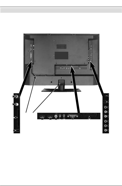
Rear of TV
TechniVision 22 HD
1 Illustrations
Rear of TV
TechniVision 22 HD (connections, attachment, cover)
1 |
|
|
|
|
|
|
|
|
|
|
|
|
|
|
|
|
|
|
|
|
|
5 |
||
|
|
|
|
|
|
|
|
|
|
|
|
|
|
|
|
|
|
|
|
|
||||
2 |
|
|
|
|
|
|
|
|
|
|
|
|
|
|
|
|
|
|
|
|
|
6 |
||
|
|
|
|
|
|
|
|
|
|
|
|
|
|
|
|
|
|
|
|
|
|
|
||
|
|
|
|
10 |
11 |
|
|
|
|
|
|
|
|
|
|
|
|
|
|
|
|
|
7 |
|
|
|
|
|
|
|
|
|
|
|
|
|
|
|
|
|
|
|
|
|
|||||
|
|
|
|
|
|
|
|
|
|
|
|
|
|
|
|
|
|
|
|
|
|
|||
|
|
|
|
|
|
|
|
|
|
|
|
|
|
|
|
|
|
|
|
|
||||
3 |
|
|
|
|
|
|
|
|
|
|
|
|
|
|
|
|
|
|
|
|
|
8 |
||
|
|
|
|
|
|
|
|
|
|
|
|
|
|
|
|
|
||||||||
|
|
|
|
|
|
|
|
|
|
|
|
|
|
|
|
|
|
|
|
|
|
|
||
|
|
|
|
|
|
|
|
|
|
|
|
|
|
|
|
|
|
|
|
|
|
|
9 |
|
4 |
|
|
|
|
|
|
|
|
|
|
|
|
|
|
|
|
|
|
|
|
|
|
||
|
|
|
|
|
|
|
|
|
|
|
|
|
|
|
|
|
|
|
|
|
|
|
||
|
|
|
|
|
|
|
|
|
|
|
|
|
|
|
|
|
|
|
|
|
|
|
||
|
|
|
|
|
|
|
|
|
|
|
|
|
|
|
|
|
|
|
|
|
|
|
|
|
|
|
|
|
|
12 |
13 141516 |
17 |
18 |
|
|
|
|
|
|
||||||||||
|
|
|
|
|
|
|
|
|
|
|
|
|||||||||||||
1 |
Antenna input |
7 |
Audio input (R, L) |
|
|
13 |
HDMI input 1 |
|||||||||||||||||
2 |
(DVB-C, DVB-T, analogue) |
(S-Video, Video and |
14 |
Audio output digital (S/P |
||||||||||||||||||||
LNB Input (DVB-S) |
component input) |
|
|
|
DIF electrical) |
|||||||||||||||||||
3 |
Common Interface |
8 |
Video input |
|
|
15 |
Headphone output |
|||||||||||||||||
4 |
USB port |
9 |
Component input |
|
|
|
(3.5mm jack plug) |
|||||||||||||||||
5 |
DC socket |
10 |
Cable guide |
|
|
16 |
Audio input (VGA/DVI) |
|||||||||||||||||
6 |
S-Video input |
11 |
Stand attachment cover |
|
(3.5mm jack plug) |
|||||||||||||||||||
|
|
|
|
|
|
12 |
HDMI input 2 |
|
|
17 |
VGA connection |
|||||||||||||
|
|
|
|
|
|
|
|
|
|
|
|
|
|
|
|
18 |
Scart socket (EuroAV) |
|||||||
2
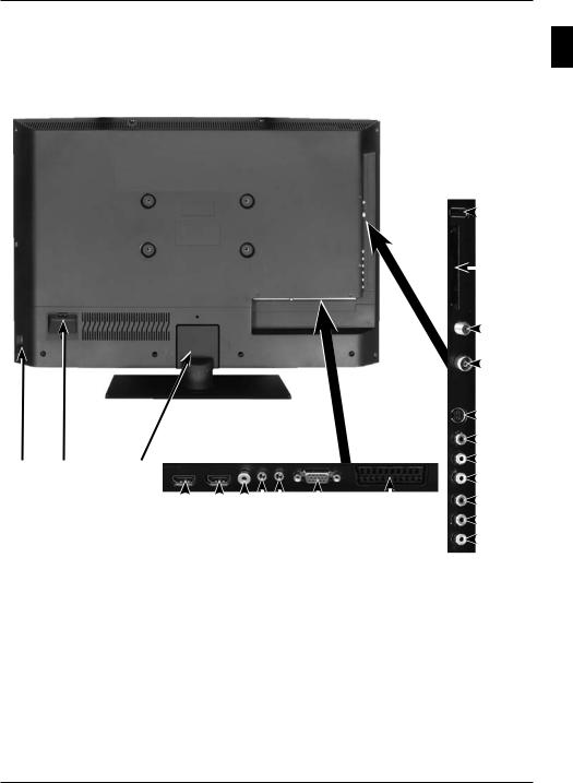
Rear of TV
TechniVision 26/32 HD
Rear of TV
TechniVision 26/32 HD
(connections, cover)
|
|
|
|
|
|
|
|
|
|
|
|
|
|
|
|
|
|
|
|
1 |
||
|
|
|
|
|
|
|
|
|
|
|
|
|
|
|
|
|
|
|
|
|||
|
|
|
|
|
|
|
|
|
|
|
|
|
|
|
|
|
|
|
|
2 |
||
|
|
|
|
|
|
|
|
|
|
|
|
|
|
|
|
|
|
|
|
|||
|
|
|
|
|
|
|
|
|
|
|
|
|
|
|
|
|
|
|
|
|
3 |
|
|
|
|
|
|
|
|
|
|
|
|
|
|
|
|
|
|
|
|
|
|||
|
|
|
|
|
|
|
|
|
|
|
|
|
|
|
|
|
|
|
|
|
4 |
|
|
|
|
|
|
|
|
|
|
|
|
|
|
|
|
|
|
|
|
|
|||
|
|
|
|
|
|
|
|
|
|
|
|
|
|
|
|
|
|
|
|
5 |
||
|
|
|
|
|
|
|
|
|
|
|
|
|
|
|
|
|
|
|
|
|||
9 |
10 |
11 |
|
|
|
|
|
|
|
|
|
|
|
|
|
|
|
|
|
|
|
6 |
|
|
|
|
|
|
|
|
|
|
|
|
|
|
|
|
|
||||||
|
|
|
|
|
|
|
|
|
|
|
|
|
|
|
|
|||||||
|
|
|
|
|
|
|
|
|
|
|
|
|
|
|
|
|
|
|
7 |
|||
|
|
|
|
|
|
|
|
|
|
|
|
|
|
|
|
|
|
|
||||
|
|
|
|
|
|
|
|
|
|
|
|
|
|
|
|
|
|
|
|
|||
|
|
|
|
|
|
|
|
|
|
|
|
|
|
|
|
|
|
|
|
8 |
||
|
|
|
|
|
|
|
|
|
|
|
|
|
|
|
|
|
|
|
|
|
|
|
|
|
|
|
|
|
|
|
|
|
|
|
|
|
|
|
|
|
|
|
|||
|
|
|
|
|
|
|
|
|
|
|
|
|
|
|
|
|
|
|
|
|
|
|
|
|
12 |
13 |
141516 |
17 |
18 |
|
|
|
|
|
|
|
|
|
|||||||
EN
1 |
USB port |
7 |
Video input |
15 |
Headphone output |
2 |
Common Interface |
8 |
Component input |
|
(3.5mm jack plug) |
3 |
LNB Input (DVB-S) |
9 |
Mains power switch |
16 |
Audio input (VGA/DVI) |
4 |
Antenna input |
10 |
Mains power connection |
|
(3.5mm jack plug) |
|
(DVB-C, DVB-T, analogue) |
11 |
Stand attachment cover |
17 |
VGA connection |
5 |
S-Video input |
12 |
HDMI input 2 |
18 |
Scart socket (EuroAV) |
6 |
Audio input (R, L) |
13 |
HDMI input 1 |
|
|
|
(S-Video, Video and |
14 |
Audio output digital |
|
|
|
component input) |
|
(S/P DIF electrical) |
|
|
3

Remote control
Remote control
Sleep timer
Sound on/off
Numeric keys
Recording
Stop
Rewind
Arrow keys
SFI
Page up
Back
Function selection
Programme +/-
Function keys
Menu
Timer
Teletext
Freeze frame / Jogshuttle
On/Standby
 Remote control code
TV/Radio mode
Fast forward
Pause / playback
DVR mode
Page down
Info
OK
Volume +/-
Option selection
Zoom/Format
Language selection
PaT
Genre
4
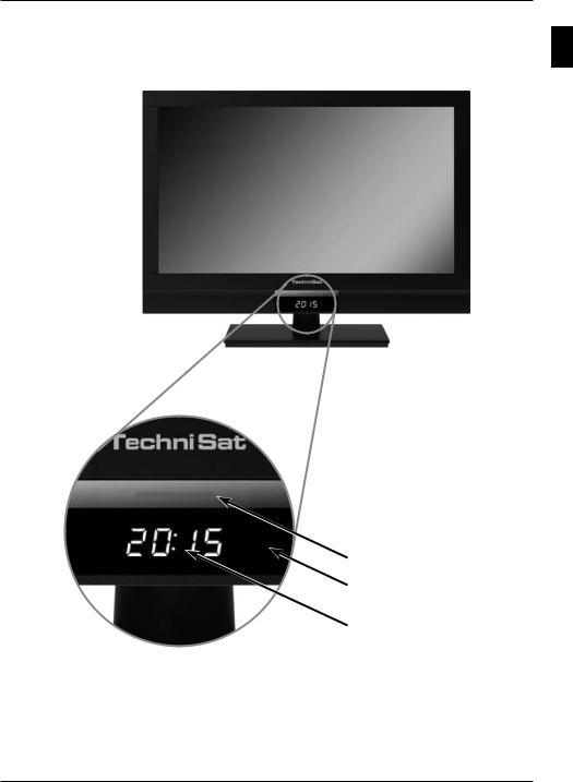
Front of TV
(Display)
Front of TV
Display
EN
LED
IR receiver
Display
5

Important instructions
2 Please read this first
Dear customer,
This quick start manual simply describes the most important connection options and the basic operating steps required for you to quickly get started operating the TechniVision 22, TechniVision 26 or TechniVision 32.
Please also definitely comply with the notes on safety provided under Point 2 of the instruction manual, appropriate use, operation, power consumption in standby mode and during operation as well as transport of and cleaning the television. You will also find information provided in this section about disposal of the packaging and the television. The manufacturer’s declaration is also provided in this section.
2.1 Intended use
>Connection to mains power 230V/50Hz (TechniVision 26 / 32 HD and TechniVision 22 HD via mains power unit supplied) or to 12 V DC power (TechniVision 22 HD)
>The TV set is intended only for the reception and playback of picture and sound signals.
>The TV is only suitable for connection to audio and video devices, antenna units and computers that meet DIN standards and have a CE mark.
Use is permitted in private and commercial situations in dry rooms and under supervision.
>Any other use is expressly forbidden.
2.2 Manufacturer’s declaration
The TV meets the following requirements:
>the EU directive 2006/95/EC (low voltage directive)
-EN 60065
>the EU directive 2004/108/EU (EMC directive)
-EN 55013, EN 55020, EN 61000-3-2
and bears the CE mark.
2.3 Important instructions
Please observe the following instructions in order to avoid any safety risks, prevent damage to the TV, and help contribute to environmental protection.
2.3.1 Safety
For your own protection you should read the safety notes carefully before using your new TV. The manufacturer accepts no liability for damage caused by inappropriate handling, or by non-compliance with the safety precautions.
Do not open the receiver housing under any circumstances! Touching parts that conduct high voltages can be fatal!
6
Important instructions
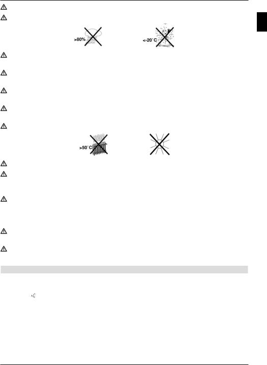
Any necessary repairs to the receiver should only be carried out by qualified personnel. Only operate the receiver in a temperate climate.
Do not switch on the TV immediately after delivery or transportation in cold weather; wait until it reaches room temperature.
Do not expose the set to dripping or sprayed water. If water gets into the unit, immediately remove the mains plug and advise the service department.
Do not place the TV on a narrow shelf or in small cabinets; ensure a minimum ventilation gap of 10cm around the unit.
The set has ventilation slits to allow heat to escape from the inside of the set. Do not cover the ventilation slits with objects such as newspapers, tablecloths etc.
Do not operate sources of heat near the TV that can additionally heat it up.
Do not place objects over the ventilation slits.
In thundery weather and when the set is not to be used for an extended period or during absence you should remove the mains and antenna plugs from the set. Overvoltage can damage the TV.
In the event of a noticeable defect on the set, if a smell is produced or if smoke comes out, if there are severe malfunctions, if there is damage to the power cable or to the casing and if liquids penetrate the set, pull the mains plug out immediately and contact the service department.
In the event of a power failure the TV should be isolated from the mains power by pulling out the plug or by switching the set off.
During long absences the TV should be switched off. This extends the lifetime of the screen and saves energy.
2.3.2 Disposal
The packaging material used for your TV consists entirely of recyclable materials. Please sort the components appropriately and dispose of them in line with your local waste disposal regulations .
At the end of its useful life span, this receiver may not be disposed of with your regular household waste. It must be taken to a recycling collection point for electrical and electronic equipment.
This is indicated by the  symbol on the product, the operating manual or the packaging.
EN
7
Important instructions
The materials can be re-cycling in accordance with their labelling.
By ensuring that valuable raw materials are re-used you can make a valuable contribution towards protecting our environment.
Please contact your local authority for the location of the nearest recycling point.
Please ensure that flat batteries removed from the remote control and electronic waste are not sent to your regular household refuse site, but are correctly disposed of either in special bins for problem waste, or at collection points in the retail trade.
2.3.3 Power consumption in Standby and during operation
The TV’s power consumption in standby and during operation depends on the settings you select, the functions you use and the devices inserted/attached such as CI modules or USB storage media.
Thus you can reduce power consumption during operation by e.g. only inserting/attaching CI modules and USB storage media if they are actually going to be used. Power consumption
during operation is also influenced by the selected picture mode and backlighting setting (Main menu > Settings > Picture Settings). The higher the backlighting is set, the
higher the power consumption too.
As the TV is not fully in standby mode during the automatic software download (Main menu > Settings > Service Settings > Software Update) for the relevant period,
power consumption can be reduced by disabling this function. Power consumption is also influenced by the standby clock and fast start functions.
8

Remote control
3 Remote control
3.1 Changing the battery
> Open the cover on the battery compartment at the rear of the remote control by pushing it in the direction of the arrow and then lifting it off.
> Insert the supplied batteries, ensuring that the poles are the right way around (indicator visible in battery compartment).
> Close the battery compartment again.
3.2 Remote control code
By switching over the remote control option it is possible to use this remote control to operate a TechniSat television and two TechniSat receivers using the same coding.
>Hold down the remote control code button to switch over the remote control option and press the OK button as often as necessary until the LED for the desired remote control option (TV, SAT1 or SAT2) flashes briefly.
The currently set remote control code will be displayed, as the appropriate LED flashes, while pressing a button.
EN
9
Connecting
4 Connecting
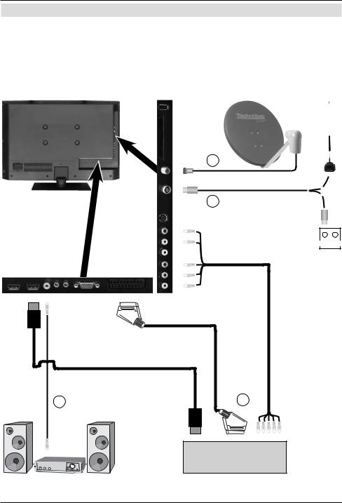
a Connecting the satellite antenna using the LNB input.
b Connecting the cable connection (digital and/or analogue) or the DVB-T antenna to the antenna input on the television.
c Connecting the television to a BluRay/DVD player using an HDMI cable or a cinch components cable with the cable adapter.
d Connecting the digital audio output to Hi-Fi stereo equipment or surround sound equipment.
a
b
TV/Radio
d |
c |
BluRay / DVD
10
Connecting
The following references a b c d refer to the example connection on page 10.
4.1 Satellite antenna
a Connect LNB input 1 on the TV to your external unit using a suitable coaxial cable.
4.2 Antenna/cable connection (analogue and digital)
bConnect the antenna input for the LCD TV to either a terrestrial antenna or to the connection socket for the cable or antenna connection.
Use the TechniSat DVB C/T Switch (Part No. 0000/3263) for simultaneous reception of DBV-T signals and DVB-C plus analogue cable channels. This switch automatically switches between DVB-T reception and reception of DVB-C and analogue cable channels, thus preventing potentially conflicting frequency influences.
4.3 BluRay/DVD player
cConnect your BluRay/DVD player using an HDMI connection cable with an HDMI connection.
4.4 Surround sound/Hi-Fi amplifier
You can connect the LCD TV to a surround sound or Hi-Fi amplifier to obtain the best possible sound quality.
dIf your amplifier has an appropriate electrical input (S/P-DIF), connect the Audio output digital electrical to the input on your amplifier.
Depending on the broadcaster concerned, the stereo signal (PCM) and, where broadcast, Dolby Digital signal (AC3) are available.
4.5 Mains power connection
TechniVision 22 HD
The TV should only be connected to the mains power supply using the adapter after cable connections to the associated components have been fully set up. This will avoid damage to the TV or other components.
>Connect the mains adapter pin connector to the DC socket (see page 2 #5).
>Then attach the mains cable to the adapter and connect it using a 230 V / 50 Hz plug.
TechniVision 26 / 32 HD
The TV should only be connected to the mains power supply using the adapter after cable connections to the associated components have been fully set up. This will avoid damage to the TV or other components.
>To do this, attach the mains cable to the mains power connection (see page 3 #10) and connect it using a 230 V / 50 Hz plug.
EN
11
Basic operation
5 Basic operation
Dear Customer,
the following section starts by covering basic operation as well as recurring operating steps for the TV. This should make it easier to read the instruction manual, since it avoids repeated description of identical steps at each individual stage.
The so-called "On Screen Display" is used on your television. This simplifies operation of the television since the buttons on the remote control can take on different functions, which makes it possible to reduce the number of buttons.
In this On Screen Display (OSD for short) the selected functions or settings are highlighted. Furthermore, you will see a line at the lower edge of the screen in which the various buttons on the remote control are shown with their current functions.
In this instruction manual the terms shown in the OSD as well as the buttons to be pressed are highlighted from the rest of the text by the display format used.
Warning - indicates an important note which you absolutely should observe in order to avoid problems with the television, loss of data or unwanted operation.
Tip - indicates a note about the function described as well as other functions associated with it and any others to be observed with reference to the respective place in the instruction manual.
5.1 Switching the television on/off
>When the TV is on standby, you can switch it on by pressing the On/Standby button.
>When operating normally you can switch the TV to standby mode by pressing the
On/Standby button.
When switching the TV on/off, also observe point 7.1 and points 7.1.1 - 7.1.4 as well as the instructions given under these points.
12
Basic operation
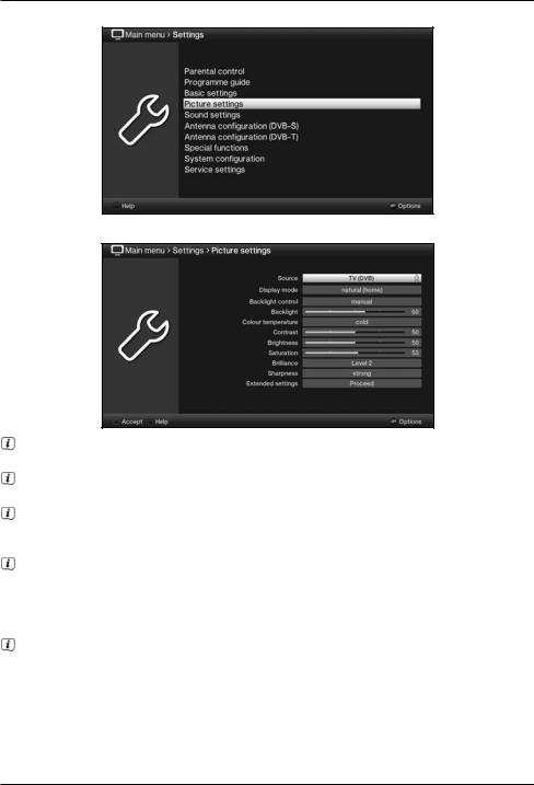
5.2 Calling up the main menu and navigating through the menus /functions
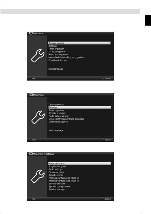
The following example will illustrate how you reach the main menu and call up a submenu. The objective of the example is to call up the Picture settings menu.
>Press the Menu button. The main menu appears on the screen.
>Select the Settings menu item by moving the highlight over this item using the arrow keys.
EN
> Press the OK button to open the Settings menu.
13
Basic operation
>Use the up/down arrow keys to highlight the Picture settings item.
>The Picture settings menu is opened by subsequently pressing the OK button.
You can also highlight the individual menu points in the same way as you highlight an item on a submenu to open it and alter the respective settings.
The menu items in some menus have to be highlighted by moving sideways. This is done by pressing the right/left arrow keys.
By pressing the up/down arrow keys it is possible to move the highlight from line to line and to move upwards and downwards page by page using the page up/down
buttons.
You will see the so-called menu path in the uppermost line of the menu. This shows
you the menu you are currently in and the path you took to reach this menu. In the example shown this is Main menu > Settings > Picture settings. The menu
path is also shown throughout the instruction manual and shows you how you can reach the respective menu with the settings described.
If the blue function key with Help is displayed in the bottom line on the screen, a Help page can be displayed by pressing this button and hidden by pressing it again.
14
 Loading...