


Quick Start Manual
TechniCorder ISIO STC
Digital Multituner HD Receiver
with Internet Access
With CONAX cardreader and an interface for recording from two CI/CI+ modules
and a DVR recording function via the optional internal hard drive, the USB interface or the home network.
For reception of free-to-air and encrypted (e.g. VIACCESS, CONAX, IRDETO, etc.)
HD satellite channels.
DiSEqC 1.2

Dear Customer,
Congratulations on your decision to purchase the TechniCorder ISIO STC.
The operating manual supplied is intended to help you to utilise the comprehensive functions of your new digital receiver to the fullest extent. We have kept the operating instructions as brief as possible and have used terminology that everybody can understand.
The range of functions of your receiver is constantly being expanded by means of software updates. This means that additional steps in the operation may be added that are not yet described in this operating manual, or the operation of existing functions may be changed. For this reason you should occasionally visit the TechniSat homepage to download the latest version of the operating manual.
We wish you many years of viewing pleasure with your TechniCorder ISIO STC!
Your
TechniSat Team
2
TechniSat hereby declares that the TechniCorder ISIO STC device complies with the fundamental requirements and any other relevant stipulations of Directive 1999/5/EC. The declaration of conformity can be viewed online at: http://www.technisat.de/konformitaet/ technicorderisiostc.pdf
The unit also bears the CE mark.

This unit is designed for use in all countries of the European Union and in Switzerland, Norway, Liechtenstein and Iceland. Operation in the 5150 MHz - 5350 MHz frequency range is only permissible in closed rooms.
HDMI, the HDMI-Logo and High Definition Multimedia Interface are trademarks or registered trademarks of HDMI Licensing LLC.
This product contains technologies which are protected by copyright, by US patents and by other rights for the protection of the intellectual property of the Rovi Corporation. Reverse engineering and disassembly are prohibited.
This item incorporates copy protection technology that is protected by U.S. patents and other intellectual property rights of Rovi Corporation. Reverse engineering and disassembly are prohibited.
Manufactured under license from Dolby Laboratories. Dolby and the double-D symbol are trademarks of Dolby Laboratories.
3

1 Illustrations
Sleep Timer
Sound on/off
Numeric keypad keys 
Recording
Stop / DVR
Rewind
Arrow keys
EPG
Page up
Back
Options selection
Channel +/-
Function keys
Menu
Timer
Teletext
Freeze frame /
Jogshuttle
On/Stand-by
 Remote control code
TV/Radio mode
Fast forward
Pause / playback
WWW
Page down
Info
OK
Volume +/-
Function selection
Zoom/Format
Audio channel
PiP/PaP
HDMI
4
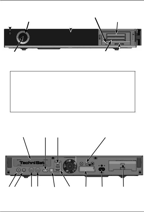
Front of unit
|
|
Arrow |
|
|
USB port |
socket |
On/Stand-by |
keys |
Display |
||||
|
|
|
|
|
|
CI modules |
|
|
|
|
|
|
|
|
|
|
|
|
|
|
|
|
|
|
|
|
|
OK |
Smartcard |
|
|
|
|||
|
SD/MMC |
||
|
card reader |
card reader |
|
|
|
|
|
Einlegen der CONAX Smartcard:
> Push the CONAX Smartcard (gold chip face down and aligned in the direction of insertion) into the Smartcard reader as far as the stop.
Inserting the CI/CI+ modules: |
|
> |
Please refer to the CI/CI+ module and card manufacturer’s instructions. |
> |
Insert the Smartcard you want into the relevant CI module. |
> |
Now carefully insert the CI module into the slot. |
Rear of unit
Tuner slot |
HDMI |
|
Network |
Audio outputs |
output |
|
port |
analogue/digital |
|
|
|
RF in |
Loop |
LNB 2 |
LNB 1 |
S/PDIF |
USB |
SCART |
Mains power |
Hard drive |
|
out |
input |
input |
out |
ports |
socket |
connection |
drawer |
5
2 Please read this first
Before connecting and using the device, first check that everything has been supplied and familiarise yourself with the safety instructions.
The delivery includes:
1 digital receiver, 1 Quick Start Manual, 1 CD-ROM,
1 remote control, 1 mains cable, batteries (2 x 1.5V microcells)
2.1 Safety advice
For your own protection you should read the safety precautions carefully before using your new receiver.
The manufacturer accepts no liability for damage caused by inappropriate handling, or by non-compliance with the safety precautions.
Function-related discharge current may occur with electrical equipment. This is acceptable and poses no risk, even if it is experienced as a slight tingling.
To prevent these discharge currents, mains operated devices (receivers, TVs etc.) must always be installed or connected with the power switched off, i.e. devices must be disconnected from the mains power supply.
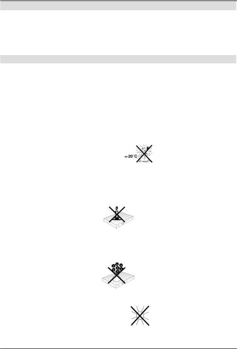
-Only operate the receiver in a temperate climate.

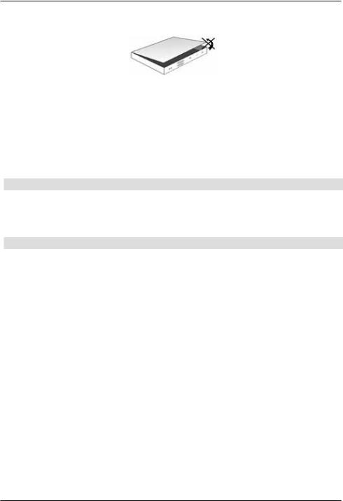
-To ensure adequate ventilation, place the receiver on a flat, horizontal surface and do not place any objects on top of it. There are ventilation slots here to allow heat to be dissipated from the interior of the unit.
-Never place any burning objects, such as lit candles, on top of the unit.
-Do not expose the receiver to water droplets or water spray, and do not place any objects filled with liquid, such as vases, on top of it. If water gets into the unit, immediately disconnect the mains plug and inform the service department.
-Do not operate any sources of heat near to the unit which may also heat it up.

-Do not obstruct the ventilation slots.
6
-Never open the receiver housing under any circumstances!! You risk receiving an electric shock. Any necessary repairs to the receiver should only be carried out by qualified service personnel.
In the following circumstances you should disconnect the device from the mains power and consult an expert:
>the power cable or mains plug is damaged
>the unit has been exposed to moisture or liquid has got into it
>there are significant malfunctions
>there is severe external damage.
2.2 Periods of non-use
During a storm or lengthy period of non-use (e.g. holiday), the receiver should be disconnected from the mains and the antenna cable removed.
Before you disconnect the receiver from the mains, you should first switch it to standby mode and wait until the time appears in the display or the red LED light is displayed.
2.3 Important notes on operation
Operation of the digital receiver is simplified through the use of so-called "On Screen Displays" (OSD). This also means that the number of keys on the remote control unit is reduced.
All functions are displayed on screen, and can be controlled by means of a few control buttons.
Functions that are logically related are combined into a "MENU". The selected function will be highlighted.
The red, yellow, blue and green function keys are indicated by coloured bars at the bottom of the screen. In the various menus, these coloured bars represent different functions, which can be implemented by pressing the appropriately coloured keys (multi-function keys) on the remote control. The function keys are only activated when a brief description is displayed in the appropriate field.
The button identifications and terms that appear in the OSD menu are shown in bold type in this operating manual.
Help: Where available, press the blue function key in the menus to display help text and press again to close the help window.
7
2.4 Important information on data security
Before handing your receiver over to your supplier for maintenance purposes, we recommend that you remove all storage media or data carriers.
Restoring data is not part of maintenance or repair work. TechniSat accepts no responsibility for the loss of, or damage to, data during repair work.
2.5 Remote control/Changing the battery
> Open the cover on the battery compartment at the rear of the remote control by pressing gently on the point indicated and pushing in the direction of the arrow.
> Insert the supplied batteries, ensuring that the poles are the right way around (indicator visible in battery compartment).
> Close the battery compartment again.
2.6 Disposal advice
The packaging material used for your receiver consists entirely of recyclable materials. Please sort the components appropriately, and dispose of them in line with your local waste disposal regulations.
At the end of its useful life span, this receiver may not be disposed of with your regular household waste. It must be taken to a recycling collection point for electrical and electronic equipment.
This is indicated by the  symbol on the product, the operating manual or the packaging.
The materials used can be re-used in accordance with their labelling.
By ensuring that valuable raw materials in old equipment are re-used, you can make a valuable contribution towards protecting our environment.
Please contact your local authority for the location of the nearest recycling point.
Please ensure that dead batteries from the remote control and electronic waste items are not sent to your regular household refuse site, but are correctly disposed of (either in special bins for problem waste, or at collection points at specialist dealers).
8
3 Optional Hardware
Your DVB receiver can also be equipped with optional hardware, such as various tuner modules and an internal 2.5” hard drive.
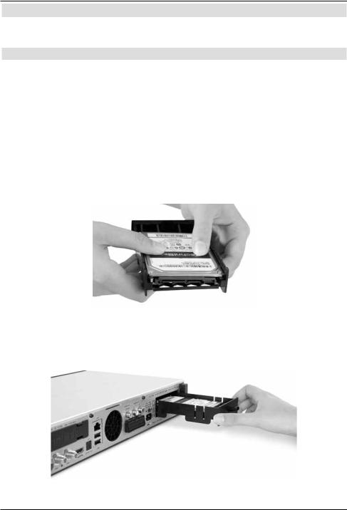
3.1 Installing the optional internal hard drive
Your DVB receiver can also be equipped with an internal 2.5” hard drive or SSD for DVR recording functionality:
a.Disconnect the unit from the mains power supply. Please also note section 2.2 (periods of non-use).
b.Now press the handle of the hard drive drawer together to release the lock and carefully remove the drawer from the housing.
c.Insert your 2.5” hard drive or SSD in the drawer with the contact strip pointing towards the open end of the drawer.
d.Now carefully click in the securing hook of the drawer first on one side of the 2.5” disc drive and then on the other. If this is not possible with light pressure, remove the hard drive from the drawer and reposition it. Depending on the disk drive being used, the underside may need to face upwards to allow it to engage.
e.Now slide the drawer into the unit until you feel slight resistance. Now carefully push the drawer further in using slight pressure to connect the disk drive with the unit. If it is not possible to push in the drawer as far as the stop using slight pressure or until the drawer engages, repeat the procedure starting from section b.) and check that the disk drive is positioned correctly.
9
f.After successfully installing the tuner module, continue with section 3.2 (Using an optional tuner module) or section 4 (Connecting the DVB receiver).
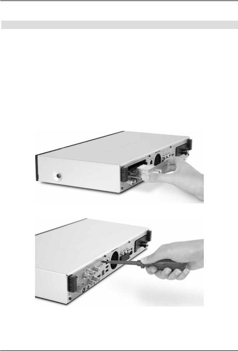
3.2 Inserting the optional tuner module
Your DVB receiver can also be equipped with an additional tuner module:
a.Disconnect the unit from the mains power supply. Please also note section 2.2 (periods of non-use).
b.Press the securing hooks on the protective cover together and remove the cover.
c.Note the printing on the tuner module to ensure that it turns in the correct position and insert the tuner module with the contact strip facing forwards into the slot which is now open.
d.Now slide the tuner module into the unit until you feel slight resistance. Now carefully push the tuner module further in using slight pressure to connect the tuner with the unit. If it is not possible to push in the tuner module as the stop using slight pressure, remove the tuner module and start again from section c.).
e.Now screw in the tuner module using the screws provided.
f.After successfully installing the tuner module, continue with section 4 (Connecting the DVB receiver).
10
3.3 Optional IsiZapper remote control
IsiZapper (item no. 0000/3773) is an optional remote control device which is specially designed for operation of Isi mode (see section 15).
On/Stand-by
Numeric keypad keys 
Sound on/off |
Teletext |
Function selection
Arrow keys |
OK |
Channel +/- |
Volume +/- |
11
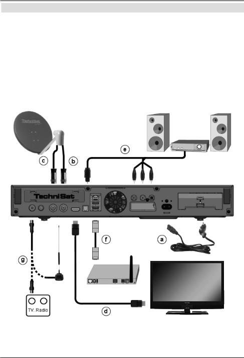
4 Connecting the DVB receiver
aNetwork connection
bLNB 1 connection to LNB Input 1 on the DVB receiver.
(Please note: the LNB must be connected with to LNB Input 1 when operating using an antenna signal.)
cLNB 2 connection to the LNB Input 2 on the DVB receiver.
d HDMI connection from the DVB receiver to the TV.
eAudio output connection to a hi-fi / surround sound system.
fDVB receiver connection to the network/internet.
gCable connection (digital) and/or the DVB-T antenna connection with the RF IN antenna input on the DVB receiver.
12
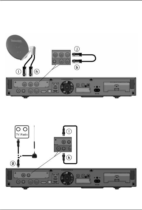
When using an optional DVB-S tuner module for operation with four antenna signals:
hAdditional connection for LNB 3 to the LNB Input 3 on the DVB receiver.
iAdditional connection for LNB 4 to the LNB Input 4 on the DVB receiver. When using an optional DVB-S tuner module for operation with one antenna signal:
hConnection for LNB 1 to the LNB Input 3 on the DVB receiver.
jConnection for the loop out to the LNB Input 1 (b) on the DVB receiver.
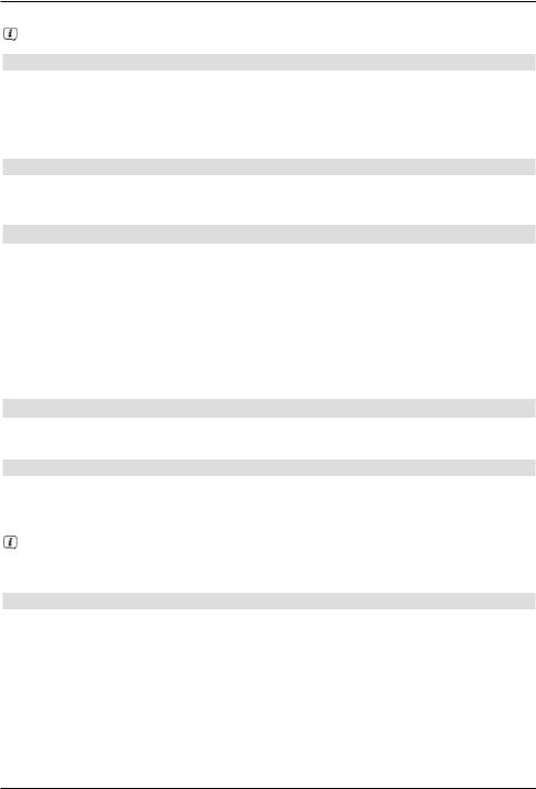
When using an optional DVB-C/T tuner module:
gCable connection (digital) and/or the DVB-T antenna connection with the RF IN antenna input on the DVB receiver.
k Connection for the loop out with the loop IN (l) of the DVB-C/T tuner module.
The following references (a b c etc.) refer to the illustrations commencing on the previous page onwards.
13

4.1 Mains power connection
The digital receiver should only be connected to the mains power supply once you have finished making all the connections to the various other components. This will prevent damage to the digital receiver or other components.
aOnce you have made all the other connections in accordance with the following sections, use the power cable supplied to connect the receiver to 230 V/50-60 Hz mains power outlet.
4.2 External unit
4.2.1 Operating the receiver with 2-4 DVB-S antenna signals
To be able to use the full scope of DVB-S functions on the digital receiver you should operate the receiver on up to four separate DVB-S antenna signals/antenna cables that which are set up identically.
If you have not installed an additional DVB-S tuner module:
b, c Connect LNB inputs 1 and 2 on the digital receiver to your external unit using a suitable coaxial cable.
or if you have installed an additional DVB-S tuner module:
b, c, i, h Connect LNB inputs 1 and 2 and LNB inputs 3 and 4 with your external unit using a suitable coaxial cable.
Also see section 8.6 (DVB-S antenna setting) in your operating manual.
4.2.2 Operating with 1 DVB-S antenna signal
In exceptional cases you can also operate the receiver using just one DVB-S antenna signal. However, in this event the recording and PIP functions are only available to a limited extent. (see section 8.6.3 in your operating manual).
If you have not installed an additional DVB-S tuner module:
bConnect the LNB Input 1 of the digital receiver to your external unit using a suitable coaxial cable
or if you have installed an additional DVB-S tuner module:
h, j, b Connect the LNB Input 3 of the digital receiver to your external unit using
a suitable coaxial cable. Now also connect the loop out output with the LNB input 1.
Also see section 8.6 (DVB-S antenna setting) in your operating manual.
4.2.3 Operating with DVB-C/T antenna signals
The digital receiver can receive signals to DVB-C or DVB-T standard. Reception in parallel with DVB-S reception is also possible
If you have not installed an additional DVB-C/T tuner module:
gConnect the RF IN antenna input on the digital receiver to your external unit using a suitable coaxial cable.
or if you have installed an additional DVB-C/T tuner module:
g, k, l Connect the antenna Input RF INon the digital receiver to your external unit using a suitable coaxial cable. Now also connect the loop out output with the
LOOP IN antenna input of the tuner module.
14
Also see section 8.6 (DVB-S antenna setting) in your operating manual.
It is not possible to receive analogue TV via the cable or antenna!
4.2.3.1 Simultaneous operation with DVB-C/T antenna signals
Use the TechniSat DVB C/T switch to receive DVB-T signals, DVB-C and DVB-C cable channels simultaneously (item no. 0000/3263). This switch automatically switches between DVB-T reception and reception of DVB-C cable channels, thus preventing potentially conflicting frequency influences. For this purpose, connect the switch output as described
in section 4.2.3.
4.2.4 Operating with a rotating system
bFor operation with a rotating system, connect the DiSEqC motor (Level 1.2) to LNB input 1.
4.3 Connecting to a TV
dConnect the receiver (HDMI output) and TV (HDMI input) via an HDMI cable.
If your TV is equipped appropriately, it will automatically switch to the HDMI input when the digital receiver is switched on.
Alternatively:
Connect the receiver (SCART socket) and TV (SCART socket) using a SCART cable. If your TV is equipped appropriately, it will automatically switch to the AV and thus to
SAT operation when the digital receiver is switched on. It may be necessary to adjust the signal type on your TV, see section 8.3.6 in your operating manual.
4.4 Hi-fi / surround sound amplifier
To achieve the best possible sound quality, you can connect your digital receiver to a hi-fi / surround sound amplifier.
4.4.1 Digital
eIf your amplifier is equipped with a suitable electrical or optical input, you should connect the AUDIO OUT DIGITAL socket electrically or optically with the electrical or optical input on your amplifier.
Depending on the signal provided by each broadcaster, sampling rates of 32, 44.1 and 48 kHz are available. In addition, where broadcast, the Dolby Digital signal is also available on this output.
4.4.2 Analogue
eTo do this, use a suitable cable to connect the cinch sockets Audio R and Audio L on the digital receivers to an input on your hi-fi amplifier.
(e.g. CD or AUX; please note that the phono input is not suitable!)
15
4.5 USB port
The USB port is used for updating the operating software and to transfer data. You can also use the film, music and image playback functions
(sections 9.18, 9.19 and 9.20 of your operating manual) to access MPEG, MP3 and JPG files on the USB storage medium.
Your unit is equipped with an internal WLAN which enables wireless integration within your existing WLAN network. However, if you wish, you can also use an external WLAN dongle for this purpose, e.g. the TechniSat USB WLAN adapter (item no. 0000/3633) or the Technisat ISIO USB WLAN adapter (item no. 0002/3633) into the USB port.
When doing so please also note section 8.5.2 (WLAN settings) in the instruction manual. It is also possible to use a Bluetooth dongle, for example to connect a Bluetooth audio receiver with the receiver.
4.6 SD / MMC card reader
The SD card reader is used for updating the operating software and transferring data (DVR recordings or image, music and video files) to or from the hard disk.
You can also use the image, music and film playback functions (sections 9.18, 9.19 and 9.20 of your operating manual) to access the corresponding files
on the SD / MMC card.
4.7 Network port (RJ45)
fYou can use the network port to connect the receiver to your existing network. This allows you to use the watchmi and internet functions, the UPnP functions, to access network drives and to use the channel provider's HbbTV applications. You can also record onto and playback from network drives.
When doing so please also note section 8.5 in your operating manual (Network Settings).
16
5 Basic operation
Dear Customer
The following section starts by covering basic operation as well as recurrent operating steps for the TV. This should make it easier to read the instruction manual, since it avoids repeated description of identical steps at each individual stage.
If a function or setting for the device has to be different from the basic operation, the difference in operation is described in detail at the relevant point in the instruction manual.
The so-called "On Screen Display" is used on your TV. This simplifies operation of the television since the buttons on the remote control can take on different functions. This makes it possible to reduce the number of buttons.
In this On Screen Display (in short OSD) the selected functions are highlighted. Furthermore, you will see a line at the bottom edge of the screen in which the various buttons on the remote control are shown with their current functions.
In this instruction manual the terms shown in the OSD and the buttons to be pressed are highlighted from other text by the print format shown.
Warning - indicates an important note which you absolutely should observe in order to avoid problems with the unit or unwanted operation.
Tip - indicates a note about the function described as well as other functions associated with it and any others to be observed with reference to the respective place in the instruction manual.
5.1 Switching the unit on/off
>When the receiver is on standby, you can switch it on by pressing the On/Standby button on the remote control/on the receiver.
>When operating normally you can switch the unit into On/Standby mode by pressing the On/Standby button.
17
5.2 Calling up the main menu and navigating through the menus /functions
The following example will illustrate how you reach the main menu and call up a submenu. The objective of the example is to call up the Picture settings
menu.
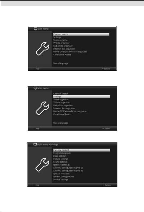
>Press the Menu button. The main menu appears on the screen.
>Select the Settings menu item by moving the highlight over this item using the arrow keys.
>Press the OK button to open the Settingsmenu.
18
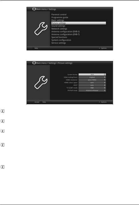
>Use the up/down arrow keys to highlight the Picture settingsitem.
>Then press the OK button to open the Picture settings menu.
You can also highlight the individual menu items in the same way as you highlight an item on a submenu to open it and alter the respective settings.
The menu items in some menus have to be highlighted by moving sideways. This is done by pressing the right/left arrow keys.
By pressing the up/down arrow keys it is possible to move the highlight from line to line and to move upwards and downwards page by page using the page up/down buttons.
You will see the so-called menu path in the uppermost line of the menu. This shows you the menu you are currently in and the path you took to reach this menu. In the example shown this is Main menu > Setting > Picture Settings. The menu path is also shown throughout the instruction manual and shows you how you can reach the respective menu with the settings described.
If the blue function key with Help is displayed on the bottom line on the screen,
a Help page can be displayed by pressing this button, and hidden again by pressing it again.
19
5.3 Accepting settings / Exiting menus and functions
In some menus and functions the changes made must be accepted manually in order to save them permanently. If this does not happen, the function or the values that existed before the change was made will be reset automatically on exiting the menu.
If an Accept field or the green function key with Accept is displayed in the bottom line of the screen, you can see that the changes made must be saved manually to be accepted.
>By highlighting Accept using the right/left arrow keys and confirming with the OK button or by pressing the green function key Accept, the changes are saved and you move back up to the next menu above.
Alternatively:
>Press the Return button.
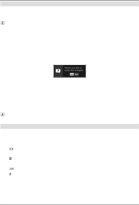
A request appears asking whether the changes you made should be applied.
>Use the right/left arrow keys Yes or No and confirm your selection by pressing the OK button.
Changes will now be saved or discarded according to your selection and you move back up to the next menu level above.
Alternatively:
>Press the Menu button to leave the menu directly.
Settings that need to be saved manually will be reset in this case..
If the green function key is not displayed on the bottom line of the screen with Accept, the changes are saved automatically on exiting the menu.
5.4 Changing a setting
You can create settings using the arrow selection method, the selection list, by entering numbers and by using the virtual keyboard. The unit specifies the method that can be used to change a highlighted setting. You can see this from the following displayed symbols:
- |
|
|
|
|
Arrow selection method (section 5.4.1) |
|
|
||||
|
|
||||
|
|
|
|
|
Arrows are shown on the left or right edge of the highlight. |
- |
|
|
|
|
Selection list (section 5.4.2) |
|
|
|
|||
|
|
|
|||
|
|
|
|
|
The symbol is shown on the right edge of the highlight. |
- |
|
|
|
|
Entering numbers (section 5.4.3) |
|
|
|
|
||
|
|
|
|
||
- |
|
|
|
|
Virtual keyboard(section 5.4.4) |
|
|
|
|
||
|
|
|
|
||
|
|
|
|
|
The symbol is shown on the right edge of the highlight. |
20
 Loading...