


TEAC SLD-90 Service manual
SL-D90
AM/FM STEREO DIGITAL
RADIO WITH CD PLAYER
PC board shown are viewed from parts side.
The parts with no reference number or no parts number
in the exploded views are not supplied.
As regards the resistors and capacitors, refer to the
circuit diagrams contained in this manual.
!
Parts marked with this sign are safety critical
components. they must be replaced with identical
components - refer to the appropriate parts list and
ensure exact replacement.
Parts of [ ] mark can be used only with the version designated.
[UL/CSA]: T/C [ME/UNI]: EX/T [JIS]: DM [IT]: EUR
[HK]: UK/HKG
1 SAFETY INFORMATION
2 SPECIFICATIONS
3 ADJUSTMENT AND CHECKS
4 EXPLODED VIEW AND PARTS LIST
5 PC BOARDS AND PARTS LISTS
6 WIRING DIAGRAM
7 INCLUDED ACCESSORIES
2
3
4
7
13
23
25
SL-D90
1 SAFETY INFORMATION
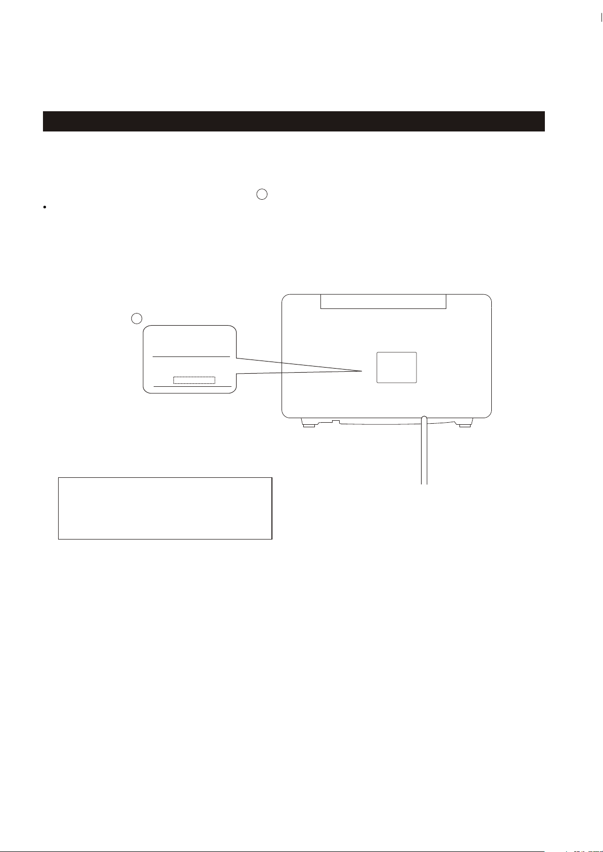
SAFETY INFORMATION
This product has been designed and manufactured according to FDA regulations " title 21, CFR, chapter 1,subchapter J,based on the
Radiation Control for Health and Safety Act of 1968" and is classified as class 1 laser product. There is not hazardous invisible laser
radiation during operation because invisible laser radiation emitted inside of this product is completely confined in the protective
housings. The label required in this regulation is shown .
CAUTION
USE OF CONTROLS OR ADJUSTMENT OR PERFORMANCE OF PROCEDURES OTHER THAN THOSE SPECIFIED HEREIN MAY RESULT IN
HAZARDOUS RADIATION EXPOSURE.
DO NOT REMOVE THE PROTECTIVE HOUSING USING SCREWDRIVER.
IF THIS PRODUCT DEVELOPS TROUBLE, MAKE A CONTACT WITH OUR SERICEMAN, AND DO NOT USE THE PRODUCT A TROUBLED STATE.
FOR U.S.A.
1
CERTIFICATION
THIS PRODUCT COMPLIES WITH DHHS
RULES 21 CFR SUBCHAPTER J APPLICABLE AT DATE OF MANUFACTURE.
TEAC CORPORATION
3-7-3, NAKA-CHO, MUSASHINO-SHI, TOKYO, JAPAN
MANUFACTURED : HKE
SERIAL
NO.
1
Optical pickup:
Type : KSM-213CDM
Manufacturer : SONY Corporation
Laser output : Less than 0.5 mW on the objective lens
Wavelength : 770 -795 nm
2

TUNER Section
Frequency Range (FM):
Frequency Range (AM):
87.5MHz to 108.00 MHz
520kHz to 1710 kHz
CD PLAYER Section
Frequency Response:
Wow and Flutter:
20 Hz to 20 kHz (+/- 1dB)
Unmeasurable
SPEAKER SYSTEM Section
Type:
Impedance:
1-way
8 ohms (L & R)
8 ohms (subwoofer)
GENERAL
Power Requirements:
Power Consumption:
Total Output Power :
Dimension (W x H x D ):
Weight:
120V AC,60Hz (U.S.A/Canada model)
120/230V AC,50-60Hz (General export model)
40 W
20 W
340 x 190 x 238.5 mm
(13-3/8 x 7-1/2 x 9-3/8) inches
5.15 kg (11-3/8 lb)
SL-D90
2 SPECIFICATIONS
Standard Accessories:
Design and specifications are subject to change without notice.
Illustrations may differ slightly from production models.
,
Owner s Manual x 1
Warranty Card x 1
Remote Control (RC-858) x 1
FM Lead-type Antenna x 1
3
SL-D90
3 ADJUSTMENTS AND CHECKS
3-1 TUNER SECTION
Use a screwdriver with a plastic or ceramic grip for all adjustment.
3-1-1 AM adjustment
1. Set the function switch to the TUNER position.
2. Set the BAND switch to the AM position.
3. Connect the test loop antenna across the output of the signal generator.
4. Connect the oscilloscope to the PHONES JACK terminal.
5. Set the signal generator as listed in the alignment chart.
3-1-2 FM adjustment
1. Set the function switch to the TUNER position.
2. Set the BAND switch to the FM position.
3. Connect the signal generator output through a 75 ohm dummy antenna to (ANT)
on TUNER PCB CN8
4. Connect the oscilloscope to the PHONES JACK terminal.
5. Set the signal generator as listed in the alignment chart.
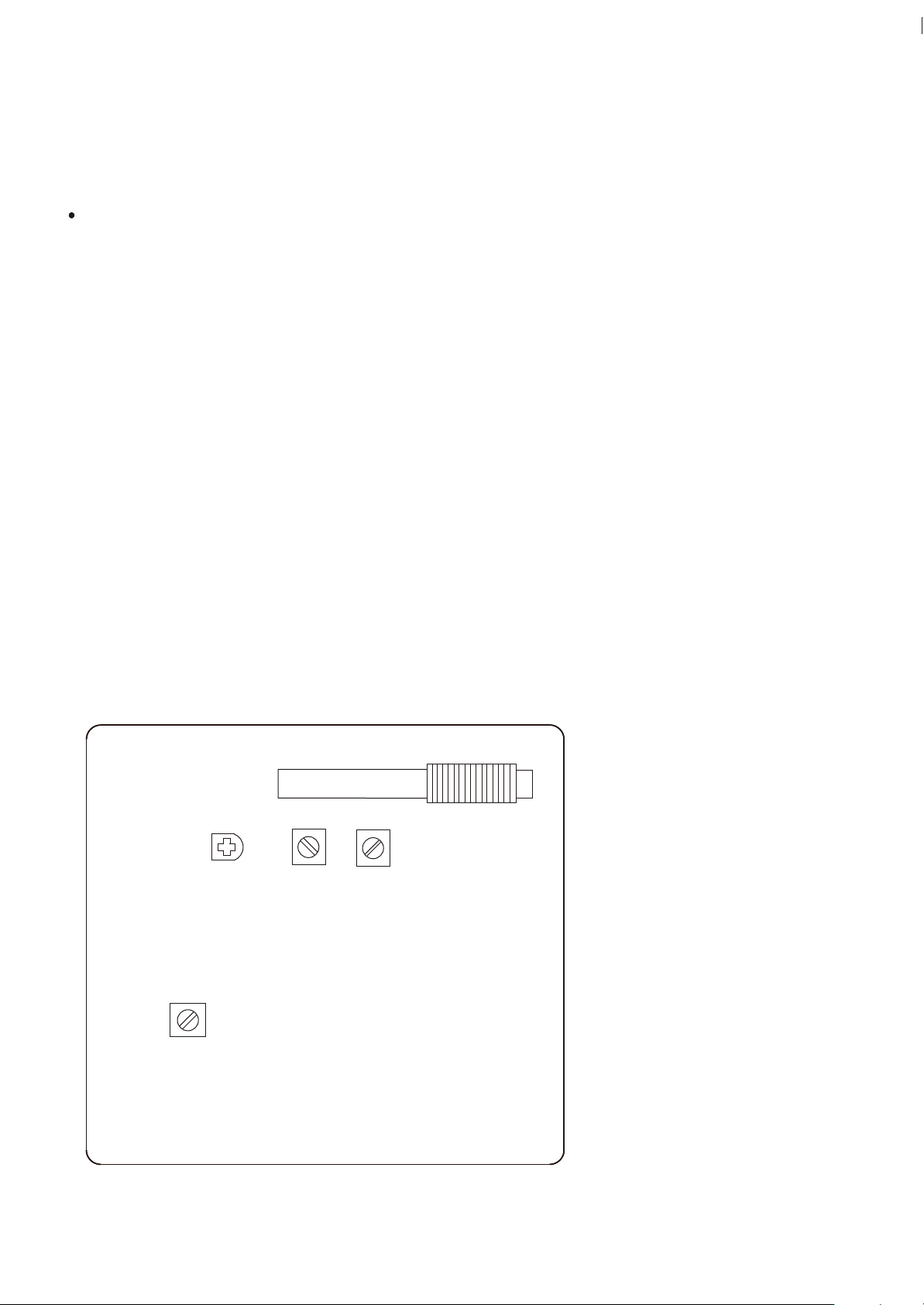
3-2 Adjustments and Test Points
TUNER PCB
TC1
L5
L4
AM ANT COIL
L6
L3
Fig. 3-2-1
4
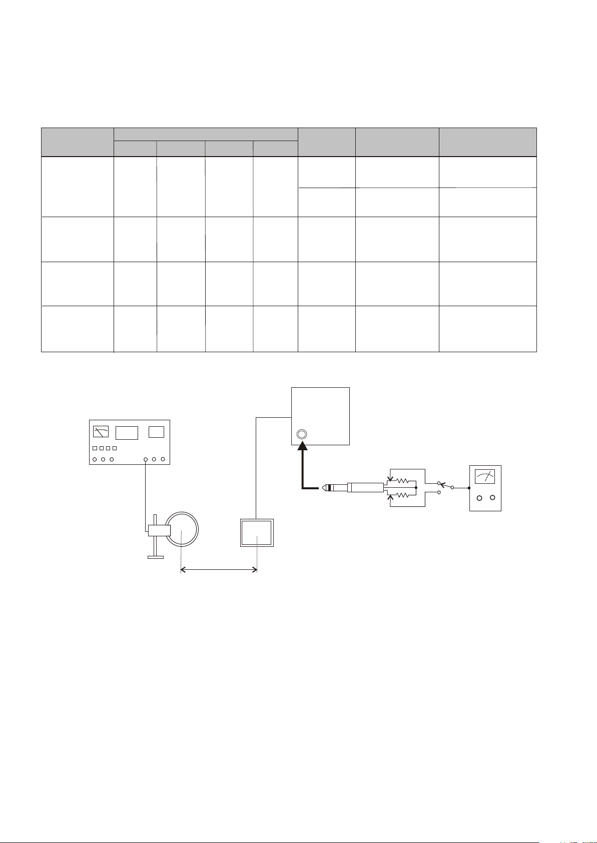
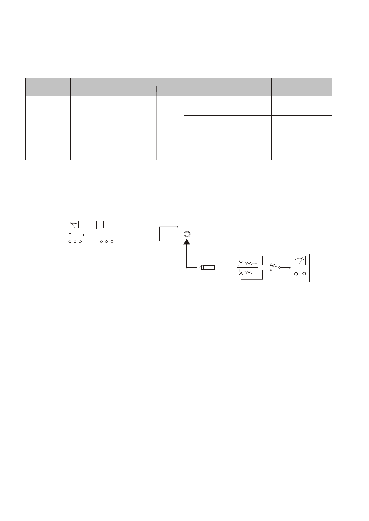
3-2-2 AM Tuner
SL-D90
ITEM
1. VOLTAGE
adjustment
2. IFT
adjustment
3. ANT coil
adjustment
4. TC1
adjustment
SIGNAL GENERATOR SETTING
Audio
1KHz
1KHz
1KHz
AM signal generator
Modulation
30%
30%
30%
Frequency
610KHz
610KHz
1410KHz
Output
76 dBuV
76 dBuV
76 dBuV
AM
TUNER
SETTING
1710KHz
530 KHz
610KHz
610KHz
1410KHz
SL-D90
ADJUSTMENTS
L4
Check
L6
AM ant coil
L3
TC1
Repeat step 3
and 4
MEASURING
POINTS, RESULT
VT
8.0V
VT
1.5V
Maximum
output level
Maximum
output level
Maximum
output level
60cm
PHONES
AC voltmeter
1 k ohm
1 k ohm
AM Loop
Antenna
Fig. 3-2-3
5
SL-D90
3-2-4 FM Tuner
ITEM
1. VOLTAGE
adjustment
2. IFT
adjustment
SIGNAL GENERATOR SETTING
Audio
1KHz
FM signal generator
Modulation
22.5KHz
Frequency
90.1MHz
75 ohm
Output
25 dBuV
FM
TUNER
SETTING
106.1MHz
90.1MHz
90.1MHz
SL-D90
PHONES
ADJUSTMENTS
Check
Check
L5
1 k ohm
MEASURING
POINTS, RESULT
VT
5.5-5.9V
VT
1.2-1.6V
Maximum
output level
AC voltmeter
Fig. 3-2-5
1 k ohm
6
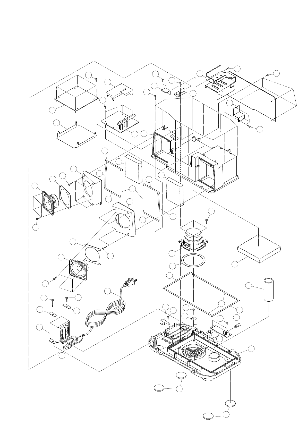
4 EXPLODED VIEWS AND PARTS LIST
EXPLODED VIEW - 1
SL-D90
4
27
42
14
36
41
3
41
7
16
14
17
36
2
35
1
5
6
14
16
11
41
10
9
39
13
14
15
12
38
8
37
40
23
24
44
39
9
26
10
23
42
25
41
28
20
18
19
36
33
43
29
45
35
30
22
32
21
20
31
34
33
7

EXPLODED VIEW-1
REF. NO
1-1
1-2
1-3
1-4
1-5
PARTS NO.
100-SD902030
011-SD900300
011-SD900200
100-SD902010
011-SD900100
DESCRIPTION
CD PCB ASSY
TUNER PCB SHIELD PLATE
HEAT SINK BRACKET
MAIN PCB ASSY
CD PCB SHIELD PLATE
SL-D90
REMARK
1-6
1-7
1-8
1-9
1-10
1-11
1-12
1-13
1-14
1-15
1-16
1-17
1-18
1-19
1-20
1-21
1-22
1-23
1-24
1-25
100-SD902040
010-SD900000
015-SD900100
061-SD900800
035-SD900082
010-SD900300
010-SD900400
035-SLD90052
035-SLD90042
035-SLD90062
099-39SLD902
035-SLD90072
061-SD900801
035-SLD90002
035-SLD90032
035-SLD90022
099-39SLD901
011-SD900400
!
084-SD900200
!
084-SD900700
!
084-SD900300
!
084-SD900100
087-00000007
087-00000027
087-00000013
087-00000001
087-00000004
TUNER PCB ASSY
SPEAKER BOX
ADIABATIC SHEET
SPEAKER 2(INCHES)
R/L SPEAKER EVA WASHER
L-SPEAKER COVER
R-SPEAKER COVER
EVA SHEET (D)
EVA SHEET(C)
EVA SHEET (E)
ABSORB COTTON 80x100x20
EVA SHEET (F)
SPEAKER 3(INCHES)
WOOFER SPK EVA WASHER
EVA SHEET (B)
EVA SHEET (A)
ABSORB COTTON 120x135x20
TRANSFORMER BRACKET
TRANSFORMER ( T/C)
TRANSFORMER (EX/T)
TRANSFORMER (DM)
TRANSFORMER (EUR,UK/HKG)
AC CORD UL (T/C)
AC CORD UL (EX/T)
AC CORD PSE (DM)
AC CORD VDE (EUR)
AC CORD BSI (UK/HKG)
7

SL-D90
EXPLODED VIEW-1
REF. NO
1-26
1-27
1-28
1-29
1-30
PARTS NO.
036-00000001
041-00000004
100-SD902070
010-SD900600
100-SD902050
DESCRIPTION
CLOSE END CONNECTOR
WIRE CLAMPER W/TUBE
HEAD PHONE JACK ASSY
CORD STOP
AUX PCB ASSY
REMARK
1-31
1-32
1-33
1-34
1-35
1-36
1-37
1-38
1-39
1-40
1-41
1-42
1-43
1-44
1-45
004-SD900700
044-SLD90040
037-SD900000
001-SD900200
001-SD900201
001-SD900202
001-SD900203
001-SD900204
001-SD900205
001-SD900206
001-SD900207
021-13006032
021-13008032
024-23008032
022-23008033
024-43010033
021-13010032
021-23014033
021-44010032
021-44012032
021-44018032
!
063-GF480300
BASE KNOB
SPEAKER PAPER TUBE
RUBBER FOOT
BOTTOM PANEL-RED (T/C,DM,EUR ,UK/HKG)
BOTTOM PANEL-WHITE (T/C,DM,EUR,UK/HKG)
BOTTOM PANEL-JADE (T/C,DM,EUR,UK/HKG)
BOTTOM PANEL-BLACK (T/C,DM,EUR,UK/HKG)
BOTTOM PANEL-RED (EX/T)
BOTTOM PANEL-WHITE (EX/T)
BOTTOM PANEL-JADE (EX/T)
BOTTOM PANEL-BLACK (EX/T)
SCREW 3x6MM PT ZMC HD
SCREW 3x8MM PT ZMC HD
SCREW 3x8MM BA ZMC HD
SCREW 3x8MM BM BLACK HD
SCREW 3x10MM PWA BLACK HD
SCREW 3x10MM PT ZMC HD
SCREW 3x14MM BT BLACK HD
SCREW 4x10MM PWT ZMC HD
SCREW 4x12MM PWT ZMC HD
SCREW 4x18MM PWT ZMC HD
AC POWER SLIDE SWITCH (EX/T)
8

SL-D90
EXPLODED VIEW - 2
35
41
22
41
17
18
19
20
38
25
24
21
23
26
8
7
6
5
13
4
2
1
3
31
10
34
39
14
12
40
11
15
5
13
16
6
35
39
9
7
36
40
30
32
46
33
44
37
40
29
45
28
27
43
42
10
46

EXPLODED VIEW-2
REF. NO
2-1
2-2
2-3
2-4
2-5
PARTS NO.
007-SD900100
004-SD900100
004-SD900200
001-SD900300
012-02120612
DESCRIPTION
LCD DISPLAY WINDOW
VOLUME KNOB
TUNER KNOB
CONTROL PANEL
PVC WASHER
SL-D90
REMARK
2-6
2-7
2-8
2-9
2-10
2-11
2-12
2-13
2-14
2-15
2-16
2-17
2-18
2-19
2-20
2-21
2-22
2-23
2-24
009-28000000
031-28000010
010-SD900700
010-SD900800
010-SD901500
004-SD900300
004-SD900500
004-SD900600
004-SD900400
010-SD901300
100-SD902020
006-SD900000
006-SD900001
006-SD900002
006-SD900003
052-SLD90000
010-SD900500
051-SLD90000
031-SD900010
100-SD902080
006-SD900100
006-SD900101
006-SD900102
006-SD900103
010-SD901100
010-SD901101
010-SD901102
010-SD901103
TUNER/VOLUME SW. LEVER
VOLUME SPRING
VOLUME SPRING COVER
TUNER SPRING COVER
POWER KNOB CAP
POWER KNOB
CD CONTROL KNOB
FUNCTION ROUND KNOB
FUNCTION KNOB
LCD BACK LIGHT HOLDER
CONTROL PCB ASSY
CD DOOR - RED
CD DOOR - WHITE
CD DOOR - JADE
CD DOOR - BLACK
CD MAGNET
CD CLAMPER
CD CLAMPER HIMERON (A)
CD DOOR SPRING
SNOOZE PCB ASSY
CD DOOR COVER - RED
CD DOOR COVER - WHITE
CD DOOR COVER - JADE
CD DOOR COVER - BLACK
CD DOOR CATCH - RED
CD DOOR CATCH - WHITE
CD DOOR CATCH - JADE
CD DOOR CATCH - BLACK
2-25
2-26
2-27
2-28
2-29
2-30
2-31
2-32
2-33
010-SD901200
002-SD900000
008-0GP18000
100-SD902060
039-SD901210
010-SD900100
051-SLD90002
010-SD900200
051-SLD90003
CD DOOR LOCK
CD BASE
GEAR DUMPER ASSY
CD SWITCH PCB ASSY
CD MECHA
L-SPEAKER GRILL
SPEAKER NET HIMERON (L)
R-SPEAKER GRILL
SPEAKER NET HIMERON (R)
11
 Loading...