


Models 150, 152, 162, & 168
Taylormate
Soft Serve Freezers
Operating Instructions
028749-M
6/98

Complete this page for quick reference when service is required:
Taylor Distributor:
Address:
Phone:
Service:
Parts:
Date of Installation:
Information found on data plate:
Model Number:
Serial Number:
Electrical Specs: Voltage |
|
Cycle |
||||||
|
Phase |
|
|
|
|
|
||
Maximum Fuse Size: |
|
|
|
|
Amps |
|||
Minimum Wire Ampacity: |
|
|
|
|
Amps |
|||
Part Number: |
|
|
|
|
|
|||
E June, 1998 Taylor All rights reserved. 028749--M
The word Taylor and the Crown design
are registered trademarks in the United States of America and certain other countries.
Taylor Company
a division of Carrier Commercial Refrigeration, Inc. 750 N. Blackhawk Blvd.
Rockton, IL 61072

Table of Contents
______________________________________________________________________________
Section 1 |
To the Installer . . . . . . . . . . . . . . . . . . . . . . . . . . . . . . . . . . . . . . . . . . . . |
1 |
Air Cooled Units . . . . . . . . . . . . . . . . . . . . . . . . . . . . . . . . . . . . . . . . . . . . . . . . . . . . . . . |
1 |
|
Electrical Hook-Up Installation for 60 Cycle, 1 Phase, |
|
|
Supplied With Cord and Plug . . . . . . . . . . . . . . . . . . . . . . . . . . . . . . . . . . . . . . . . . . . |
1 |
|
Electrical Connections for Models Without Cord and Plug Supplied . . . . . . . . . . |
1 |
|
Section 2 |
To the Operator . . . . . . . . . . . . . . . . . . . . . . . . . . . . . . . . . . . . . . . . . . . |
2 |
Compressor Warranty Disclaimer . . . . . . . . . . . . . . . . . . . . . . . . . . . . . . . . . . . . . . . |
2 |
|
Section 3 |
Safety . . . . . . . . . . . . . . . . . . . . . . . . . . . . . . . . . . . . . . . . . . . . . . . . . . . . |
3 |
Section 4 |
Operator Parts Identification . . . . . . . . . . . . . . . . . . . . . . . . . . . . . . . |
4 |
Model 150 . |
. . . . . . . . . . . . . . . . . . . . . . . . . . . . . . . . . . . . . . . . . . . . . . . . . . . . . . . . . . . |
4 |
Model 152 . |
. . . . . . . . . . . . . . . . . . . . . . . . . . . . . . . . . . . . . . . . . . . . . . . . . . . . . . . . . . . |
5 |
Model 162 . |
. . . . . . . . . . . . . . . . . . . . . . . . . . . . . . . . . . . . . . . . . . . . . . . . . . . . . . . . . . . |
6 |
Model 168 . |
. . . . . . . . . . . . . . . . . . . . . . . . . . . . . . . . . . . . . . . . . . . . . . . . . . . . . . . . . . . |
7 |
Models 150 & 152 Door Assembly . . . . . . . . . . . . . . . . . . . . . . . . . . . . . . . . . . . . . . . |
8 |
|
Models 162 & 168 Door Assembly . . . . . . . . . . . . . . . . . . . . . . . . . . . . . . . . . . . . . . . |
9 |
|
Section 5 |
Important: To the Operator . . . . . . . . . . . . . . . . . . . . . . . . . . . . . . . . . |
10 |
Push-Button Switch . . . . . . . . . . . . . . . . . . . . . . . . . . . . . . . . . . . . . . . . . . . . . . . . . . . . |
10 |
|
Power Switch . . . . . . . . . . . . . . . . . . . . . . . . . . . . . . . . . . . . . . . . . . . . . . . . . . . . . . . . . |
10 |
|
Temperature Control . . . . . . . . . . . . . . . . . . . . . . . . . . . . . . . . . . . . . . . . . . . . . . . . . . . |
10 |
|
Air Tube . . |
. . . . . . . . . . . . . . . . . . . . . . . . . . . . . . . . . . . . . . . . . . . . . . . . . . . . . . . . . . . |
11 |
Taylor Quality Control . . . . . . . . . . . . . . . . . . . . . . . . . . . . . . . . . . . . . . . . . . . . . . . . . . |
11 |
|
Indicator Light -- “Mix Low” . . . . . . . . . . . . . . . . . . . . . . . . . . . . . . . . . . . . . . . . . . . . . |
11 |
|
Mix Refrigeration Switch . . . . . . . . . . . . . . . . . . . . . . . . . . . . . . . . . . . . . . . . . . . . . . . |
11 |
|
Separate Hopper Refrigeration (SHR) . . . . . . . . . . . . . . . . . . . . . . . . . . . . . . . . . . . |
12 |
|
Cylinder Temperature Retention (CTR) . . . . . . . . . . . . . . . . . . . . . . . . . . . . . . . . . . . |
12 |
|
Syrup Rail . |
. . . . . . . . . . . . . . . . . . . . . . . . . . . . . . . . . . . . . . . . . . . . . . . . . . . . . . . . . . . |
12 |
Section 6 |
Operating Procedures . . . . . . . . . . . . . . . . . . . . . . . . . . . . . . . . . . . . . |
13 |
Assembly . |
. . . . . . . . . . . . . . . . . . . . . . . . . . . . . . . . . . . . . . . . . . . . . . . . . . . . . . . . . . . |
14 |
Sanitizing . |
. . . . . . . . . . . . . . . . . . . . . . . . . . . . . . . . . . . . . . . . . . . . . . . . . . . . . . . . . . . |
17 |
Priming . . . |
. . . . . . . . . . . . . . . . . . . . . . . . . . . . . . . . . . . . . . . . . . . . . . . . . . . . . . . . . . . |
19 |
Closing Procedure . . . . . . . . . . . . . . . . . . . . . . . . . . . . . . . . . . . . . . . . . . . . . . . . . . . . |
20 |
|
Draining Product From the Freezing Cylinder . . . . . . . . . . . . . . . . . . . . . . . . . . . . . |
20 |
|
Rinsing . . . |
. . . . . . . . . . . . . . . . . . . . . . . . . . . . . . . . . . . . . . . . . . . . . . . . . . . . . . . . . . . |
20 |
Cleaning . . |
. . . . . . . . . . . . . . . . . . . . . . . . . . . . . . . . . . . . . . . . . . . . . . . . . . . . . . . . . . . |
20 |
Disassembly . . . . . . . . . . . . . . . . . . . . . . . . . . . . . . . . . . . . . . . . . . . . . . . . . . . . . . . . . . |
21 |
|
Brush Cleaning . . . . . . . . . . . . . . . . . . . . . . . . . . . . . . . . . . . . . . . . . . . . . . . . . . . . . . . |
21 |
|
Table of Contents |
Models 150, 152, 162, 168 |

Section 7 Important: Operator Checklist . . . . . . . . . . . . . . . . . . . . . . . . . . . . . . 22
During Cleaning and Sanitizing . . . . . . . . . . . . . . . . . . . . . . . . . . . . . . . . . . . . . . . . . 22
Troubleshooting Bacterial Count . . . . . . . . . . . . . . . . . . . . . . . . . . . . . . . . . . . . . . . . 22
Regular Maintenance Checks . . . . . . . . . . . . . . . . . . . . . . . . . . . . . . . . . . . . . . . . . . . 22
Winter Storage . . . . . . . . . . . . . . . . . . . . . . . . . . . . . . . . . . . . . . . . . . . . . . . . . . . . . . . . 23
Section 8 Troubleshooting Guide . . . . . . . . . . . . . . . . . . . . . . . . . . . . . . . . . . . . 24
Section 9 Parts Replacement Schedule . . . . . . . . . . . . . . . . . . . . . . . . . . . . . . . 27
Section 10 Parts List . . . . . . . . . . . . . . . . . . . . . . . . . . . . . . . . . . . . . . . . . . . . . . . . . 28
Wiring Diagrams . . . . . . . . . . . . . . . . . . . . . . . . . . . . . . . . . . . . . . . . . . . . . . . . . . . . . . 37
Note: Continuing research results in steady improvements; therefore, information in this manual is subject to change without notice.
Models 150, 152, 162, 168 |
Table of Contents |

Section 1 |
To the Installer |
Air Cooled Units
The models 150 and 152 require a minimum of 6” (152 mm) of clearance around both sides. Install the skirt provided on the right side of the unit and place the back of the unit against a wall to prevent recirculation of warm air. The model 162 requires 6” (152 mm) on all sides and the skirt installed on the rear of the unit. The model 168 requires 3” (76 mm) on all sides and the skirt installed on the rear of the unit. Minimum air clearances must be met to assure adequate air flow for optimum performance.
These machines are designed for indoor use only.
 DO NOT install the machines in an area where a water jet could be used. Failure to follow this instruction may result in serious electrical shock.
Electrical Hook-Up Installation For
60 Cycle, 1 Phase, Supplied With Cord and Plug
This equipment is supplied with a 3-wire cord and grounding type plug for connection to a single phase, 60 cycle, branch circuit supply. This unit must be plugged into a properly grounded receptacle. The cord and plug provided for 115/60/1, is 20 amp; therefore the wall outlet must also be 20 amp. Check the data label, located on the side panel, for electrical specifications.
Permanent wiring may be employed if required by local codes. Instructions for conversion to permanent wiring are as follows:
1.Be sure the freezer is electrically disconnected.
2.Remove the appropriate panel and locate the small electrical box at the base of the freezer.
3.Remove the factory-installed cord and strain relief bushing.
4.Route incoming permanent wiring through 7/8” (22 mm) hole in base pan.
5.Connect two power supply leads. Attach ground (earth) wire to the grounding lug inside the electrical box.
6.Be sure the unit is properly grounded before applying power.
FOLLOW YOUR LOCAL ELECTRICAL CODES!
Electrical Connections For
Models Without Cord and Plug Supplied
Each freezer requires one power supply for each data label. Check the data label(s) on the freezer for fuse, circuit ampacity and electrical specifications. Refer to the wiring diagram provided inside of the control box, for proper power connections.
In the United States, this equipment is intended to be installed in accordance with the National Electrical Code (NEC), ANSI/NFPA 70--1987. The purpose of the NEC code is the practical safeguarding of persons and property from hazards arising from the use of electricity. This code contains provisions considered necessary for safety. Compliance therewith and proper maintenance will result in an installation essentially free from hazard! In all other areas of the world, equipment should be installed in accordance with the existing local codes. Please contact your local authorities.
Stationary appliances which are not equipped with a power cord and a plug or other device to disconnect the appliance from the power source must have an all--pole disconnecting device with a contact gap of at least 3 mm installed in the external installation.
 CAUTION: This equipment must be properly grounded! Failure to do so can result in severe personal injury from electrical shock!
Beater rotation must be clockwise as viewed looking into the freezing cylinder.
Note: The following procedures should be performed by an authorized service technician.
To correct rotation on a three-phase unit, interchange any two incoming power supply lines at freezer main terminal block only. To correct rotation on a single-phase unit, change the leads inside the beater motor. (Follow diagram printed on motor.)
Electrical connections are made directly to the terminal block provided in the splice box, mounted on the base pan on each side of the model 168, and located in the splice boxes mounted mid-level on the frame channel on the sides of the model 162.
031030
Models 150, 152, 162, 168 |
1 |
To the Installer |
|
|
|

Section 2 |
To the Operator |
|
|
The freezer you have purchased has been careeru3n4s50818
050818
To the Operator |
2 |
Models 150, 152, 162, 168 |
|
|
|
Section 3 |
Safety |
|
|
We at Taylor Company are concerned about the safety of the operator when he or she comes in contact with the freezer and its parts. Taylor has gone to extreme efforts to design and manufacture built-in safety features to protect both you and the service technician. As an example, warning labels have been attached to the freezer to further point out safety precautions to the operator.
 IMPORTANT! Failure to adhere to the following safety precautions may result in severe personal injury. Failure to comply with these warnings may damage the machine and its components. Component damage will result in part replacement expense and service repair expense.
SDO NOT allow untrained personnel to operate this machine.
SDO NOT put objects or fingers in door spout.
SDO NOT operate the freezer unless all service panels and access doors are restrained with screws.
SDO NOT remove the freezer door or beater assembly unless the control switches are in the “OFF” position.
Failure to follow these instructions may result in severe personal injury from hazardous moving parts.
To Operate Safely:
 DO NOT operate the freezer without reading this operator’s manual. Failure to follow this instruction may result in equipment damage, poor freezer performance, health hazards, or personal injury.
SDO NOT operate the freezer unless it is properly grounded.
SDO NOT operate the freezer with larger fuses than specified on the freezer data label.
SDO NOT attempt any repairs unless the main power supply to the freezer has been disconnected.
Failure to follow these instructions may result in electrocution. Contact your local authorized Taylor Distributor for service.
 DO NOT use a water jet to clean or rinse the freezer. Failure to follow these instructions may result in serious electrical shock.
031030
Models 150, 152, 162, 168 |
3 |
Safety |
|
|
|
Section 4 Operator Parts Identification
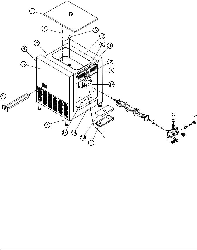
Model 150
Operator Parts Identification |
4 |
Models 150, 152, 162, 168 |
Model 152
Item |
Description |
Part No. |
|
|
|
1 |
Hopper Cover Assembly |
X48690 |
|
|
|
2 |
Feed Tube |
025061 |
|
|
|
3 |
Float A.-Mix Level |
X39690 |
|
|
|
4 |
Back Panel |
025868-SS |
|
|
|
5 |
Left Side Panel |
028591-SS |
|
|
|
6 |
Drip Pan |
027503 |
|
|
|
7 |
Leg-Plastic |
024755 |
|
|
|
8 |
Mix Low Light |
039708 |
|
|
|
9 |
Right Side Panel |
025867-SS |
|
|
|
Item |
Description |
Part No. |
|
|
|
10 |
Splash Shield |
025063 |
|
|
|
11 |
Drip Tray |
025062 |
|
|
|
12 |
Decorative Decal |
047667 |
|
|
|
13 |
Panel A.-Front |
X25036 |
|
|
|
14 |
Trim-Front |
025862-SS |
|
|
|
15 |
Trim-Top Back |
025866 |
|
|
|
16 |
Plate-Decorative |
041034-SS |
|
|
|
17 |
Hood Assembly |
X49065 |
|
|
|
18 |
Holder-Drip Tray |
035866 |
|
|
|
Models 150, 152, 162, 168 |
5 |
Operator Parts Identification |
|
|
|

Model 162
Operator Parts Identification |
6 |
Models 150, 152, 162, 168 |
Model 168
Models 150, 152, 162, 168 |
7 |
Operator Parts Identification |

Models 150 & 152 Door Assembly
Operator Parts Identification |
8 |
Models 150, 152, 162, 168 |
|
|
|
Models 162 & 168 Door Assembly
Models 150, 152, 162, 168 |
9 |
Operator Parts Identification |
Section 5 |
Important: To the Operator |
|
|
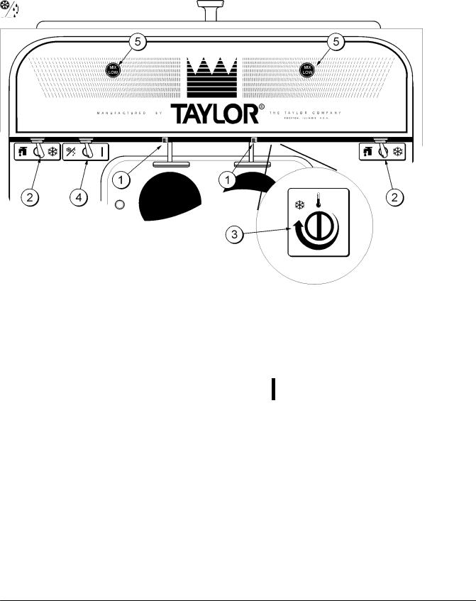
Item |
Description |
|
|
1 |
Push Button Switch |
2 |
Power Switch |
|
|
3 |
Temperature Control |
|
|
4 |
Mix Refrigeration Switch |
|
|
5 |
Indicator Lights -- “Mix Low” |
|
|
Figure 1
The following chart identifies the symbol definitions used on the operator switches.
= The ON/AUTO keypad.
= The ON keypad.
= The OFF keypad.
Symbol Definitions
To better communicate in the International arena, the words on many of our operator switches and buttons have symbols to indicate their functions. Your Taylor equipment is designed with these International symbols.
=The WASH keypad.
=The STANDBY keypad.
Important: To the Operator |
10 |
Models 150, 152, 162, 168 |
|
|
|

Push-Button Switch
If an overload condition occurs, the freezer will automatically stop operating. To properly reset the freezer, place the toggle switch in the “OFF” position. Wait two or three minutes; then press the push-button switch. Place the power switch in the “WASH” position and observe the freezer’s performance; place the power switch in the “AUTO” position.
Note: If the freezer is unplugged from the wall receptacle, it will be necessary to press the push-button switch for the freezer to operate once power is re-established.
Power Switch
The center position is “OFF”. The left position is “WASH” which activates the beater motor only. The right position is “AUTO”, which activates the beater motor and the refrigeration system.
Figure 2
Note: During “AUTO” operation, the orifice end of the tube should be inserted in the hole in the hopper.
Temperature Control
The Models 150 and 152 use a temperature control to monitor the product in the freezing cylinder. Turning the adjusting knob clockwise will decrease the product temperature. Turning the adjusting knob counterclockwise will increase the temperature. Each quarter of a turn will vary the temperature approximately two degrees. DO NOT set the temperature control colder than 18_F (-8_C). Should you set the temperature colder than 18_F (-8_C), premature failure of the belts and of the beater motor may occur.
Taylor Quality Control
The Models 162 and 168 use a solid state control called the T.Q.C. The purpose of this solid state control is to sense the viscosity (thickness) of the product in the freezing cylinder. With the power switch in the “AUTO” position, the T.Q.C. will automatically keep the mix in the freezing cylinder at the proper viscosity and ready for serving.
The Models 150 and 152 are available with the T.Q.C. as an option.
Air Tube
The models 150, 152, 162 and 168 are called upon to handle a large variety of products (i.e., soft serve, yogurts, Italian ices, sherbets, etc.). Thus, the consistency of the mix you use will vary. The air tube meters a combination of mix and air into the freezing cylinder. If not enough mix enters the freezing cylinder, a freeze-up may occur, which will cause eventual damage to the beater. Depending upon the product being run, you may wish to contact your local authorized Taylor Distributor to make a slight adjustment in the air tube.
Indicator Light - “Mix Low”
A mix level indicating light is located at the front of the machine. When the light is on, it indicates that the mix hopper has a low supply of mix and should be refilled as soon as possible. Always maintain at least 2” (5.1 cm) of mix in the hopper. If you neglect to add mix, a freeze-up may occur. This will cause eventual damage to the beater assembly and to the freezer door.
Models 150, 152, 162, 168 |
11 |
Important: To the Operator |
|
|
|
 Loading...