


.. TASCAM
.. TEAC Professional Division
. 7733 Telegraph Road
. Montebello, CA 90640
.. Phone (323) 726-0303
. Fax (323) 727-7632
.
|
MODEL: |
FX-D1000 |
|
For Details, Contact: |
|
||
Installation Instructions |
|||
Operation Support Group |
|||
|
|
||
TEAC America, Inc. (323) 726-0303
INSTALLATION INSTRUCTIONS
MODELS AFFECTED: TM-D1000
SOFTWARE LEVEL: Your TM-D1000 MUST be at software level 1.18 or higher for this option to work properly. To check your software revision level:
Power up the TM-D1000.
1) Press SHIFT and MEMO. The display should read:
Option Monitor |
> |
Mode |
V |
2) Push DATA ENTRY button downwards 4 times until “SYSTEM” appears.
Option Monitor |
> |
System |
V |
3) Rotate “DATA ENTRY(PUSH)” knob clockwise until the version appears.
TM-D1000 <
Ver1.18
If the software version is LESS than 1.18, the internal programmable logic device (PLD) must be updated. Included in this FX-D1000 package is a new PLD with the most current software available at the time of manufacturing. Instructions on how to change the PLD are included in this document.
If the software in your console is already version 1.18 or higher, please return the provided PLD in the preaddressed envelope included with your FX-D1000. This will allow us to help other customers and keep the costs of these options to a minimum.
_____________________________________________________________________________
CAUTION
To avoid damaging any of the electronic components, by means of static electricity, please wear the included grounding wrist strap before starting the installations.
STEP 1: Removing the bottom panel:
Take care not to use a long screw here. Only
on a paddedUse the 3x5 screw .
4 pcs M3x8 for the corners of the rear panel
Disconnect the power cable and any audio cables. Turn the unit over
. . . . . . . . . . . . . . . . . . . . . .
6 pcs M3x8 for the side
|
TASCAM |
|
|
|
FX-D1000 |
|
|
10/08/99 |
|||||
|
TEAC Professional Division |
|||||
|
|
|
|
Page 2 of 6 |
||
|
7733 Telegraph Road |
|
|
|
||
|
Montebello, CA 90640 |
|
|
|
|
|
|
Phone (323) 726-0303 |
|
|
|
|
|
|
|
|
INSTALLATION INSTRUCTIONS |
|
|
|
|
Fax (323) 727-7632 |
|
|
|
|
|
|
|
|
|
|
|
|
|
|
|
|
|
|
|
|
|
|
|
|
|
|
|
|
|
|
|
|
|
FIGURE 1.1
IMPORTANT WARNING!!! Special care should be taken when re-installing the bottom cover screws. As the diagram above shows, the screws MUST be reinstalled in the same position as they were removed. Note the location of the special 5mm screw! If an 8mm screw is installed where the 5mm screw was removed, the extra penetration by the 8mm screw may short circuit the electronics.
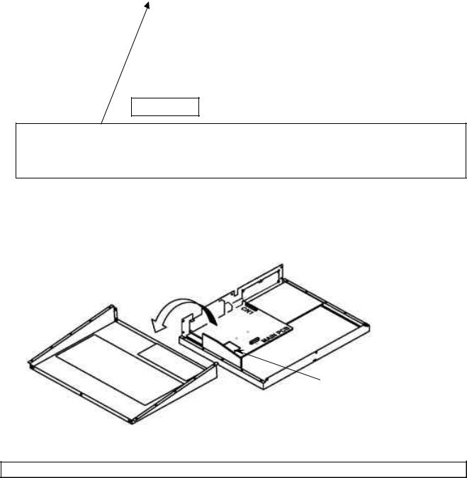
STEP 2: Removing and positioning the bottom panel: Remove the rack-mounting flanges if installed. After removing all the screws identified in the above illustration, remove the bottom cover of your TMD1000. It may be necessary to use a soft prying device like a wooden stick to loosen the bottom panel from the top panel.
Precaution:
To avoid damage to the wires linking Main and Power Supply PCB Assy, place the bottom panel beside the main unit as indicated below.
|
|
U17 |
|
|
|
|
FIGURE 1.2 |
|
If |
|
6! If you need |
|
||
to upgrade continue on to step 3. |
|
|
UPGRADING THE TM-D1000 INTERNAL PLD TO THE LATEST SOFTWARE REVISION LEVEL:
STEP 3: Removing U17, Main PLD: Locate U17 on the Main PCB as shown in the diagram (Figure 1.2). The PLD is held in place with a rectangular black plastic locking device. Slide the locking device down or toward you. Remove it by lifting straight up from the main PCB. Remove the PLD and place it
 Loading...