


MMR-8
»
MMR-8
Modular Multitrack Recor der
CUT
EVENT
REC
INPUT
CLIP
MAX
+12
+6
0
-6
-12
-25
2 3
COPY
SEL
MON INPUT
PHONES
MMR-8
REC
INPUT
CLIP
MAX
+12
+6
0
-6
-12
-25
SLIP
CLEAR
SEL
REC
INPUT
CLIP
MAX
+12
+6
0
-6
-12
-25
SLIP
4 5
PASTE
SEL
ON
LINE
REC
REC
REC
REC
SAFE
INPUT
INPUT
CLIP
CLIP
MAX
MAX
+12
+12
+6
+6
0
0
-6
-6
-12
-12
-25
-25
SLIP
SLIP
6 7
INSERT
OPEN
SEL
SEL
SEL
DELETE
LOAD
VIEW
TRACK
TRACK
UNMOUNT
DESTRUCTIVE
INPUT
INPUT
24-BIT REC
CLIP
CLIP
DIG IN
MAX
MAX
TONE
+12
+12
MIDI
+6
+6
ERROR
0
0
BUSY
-6
-6
LOCK
-12
-12
CAL
-25
-25
OFFSET
INTERLOCKSLIP
SLIP
SLIP
8
UNDO
REDO
SEL
UNLOAD
BACKUP
SLIP
TRACK
MOUNT
CAPT
LYNX SYNC
CANCEL
CLR
TIME
7
OUT
4
OFST
REH0REC
NEXT EDIT
HEADIN
8
TAIL
5
RDR
21
PREV EDIT
SHIFT
9
YES
STO
6
=
FREE
NO
RCL
3
LOOP
LOC
REC
INPUT
CLIP
MAX
+12
+6
0
-6
-12
-25
SLIP
1
SEL
EDIT
OWNER’S MANUAL
TRANSPORT
REC TYPE
TIME CODE
WAVEFRAME
OMF
Pro Tools
OTHER
29.97
NDF
DF
25
24
REFERENCE
CONTROL
FRAME
SAMPLE
R
RATE
SETUP
MODE
LOCAL/BUS
VIDEO
INT
TC CHASE
TC
AES
BIPH
WORD
BIPH CHASE
MMR
BIPH TRAN
LYNX
EXT RSLV
SER TRAN
SYNC GRP
48.000
EDITOR
44.100
1
VARI
2
MMR LYNX
P. UP
P. DOWN
3
MAST
4
NON STD.
SLAVE
SUBF
+/-
TC/FEET
-
+
TRIM
JOG
TRIM
SHTL
POWER
IDENT
D00000000A
WARNING: TO PREVENT FIRE OR SHOCK
APPLIANCE TO RAIN OR MOISTURE.
CAUTION: TO REDUCE THE RISK OF ELECTRIC SHOCK,
The exclamation point within an equilateral triangle is intended to alert the user
The lightning flash with arrowhead symbol, within an equilateral triangle, is
Alternating
Protective
CAUTION
RISK OF ELECTRIC SHOCK
DO NOT OPEN
intended to alert the user to the presence of uninsulated “dangerous
voltage” within the product’s enclosure that may be of sufficient magnitude
to constitute a risk of electric shock to persons.
to the presence of important operating and maintenance (servicing)
instructions in the literature accompanying the appliance.
DO NOT REMOVE COVER (OR BACK). NO USERSERVICEABLE PARTS INSIDE. REFER SERVICING TO
QUALIFIED SERVICE PERSONNEL.
Current
Conductor Terminal
HAZARD, DO NOT EXPOSE THIS
CAUTION:
Replace battery with Panasonic or Maxell, model CR2032 only. Use of
another battery may present a risk of fire or explosion. See owner’s
manual for safety instructions
For U.S.A
TO THE USER
This equipment has been tested and found to comply
with the limits for a Class A digital device, pursuant to
Part 15 of the FCC Rules. These limits are designed
to provide reasonable protection against harmful
interference when the equipment is operated in a
commercial environment. This equipment generates,
uses, and can radiate radio frequency energy and, if
not installed and used in accordance with the
instruction manual, may cause harmful interference
to radio communications. Operation of this equipment
in a residential area is likely to cause harmful
interference in which case the user will be required to
correct the interference at his own expense.
CAUTION
Changes or modifications to this equipment not
expressly approved by TEAC CORPORATION for
compliance could void the user's authority to operate
this equipment.

IMPORTANT SAFETY INSTRUCTIONS
CONSIGNES DE SECURITE
SICHERHEITSHINWEISE
NORME DI SICUREZZA
INSTRUCCIONES DE SEGURIDAD
VEILIGHEIDSVOORSCHRIFTEN
TEAC CORPORATION
Important Safety Instructions
CAUTION:
• Read all of these Instructions.
• Save these Instructions for later use.
• Follow all Warnings and Instructions marked on the audio
equipment.
1) Read Instructions — All the safety and operating instructions
should be read before the product is operated.
2) Retain Instructions — The safety and operating instructions should
be retained for future reference.
3) Heed Warnings — All warnings on the product and in the operating
instructions should be adhered to.
4) Follow Instructions — All operating and use instructions should be
followed.
5) Cleaning — Unplug this product from the wall outlet before cleaning.
Do not use liquid cleaners or aerosol cleaners. Use a damp cloth for cleaning.
6) Attachments — Do not use attachments not recommended by the
product manufacturer as they may cause hazards.
7) Water and Moisture — Do not use this product near water _for
example, near a bath tub, wash bowl, kitchen sink, or laundry tub; in a wet
basement; or near a swimming pool; and the like.
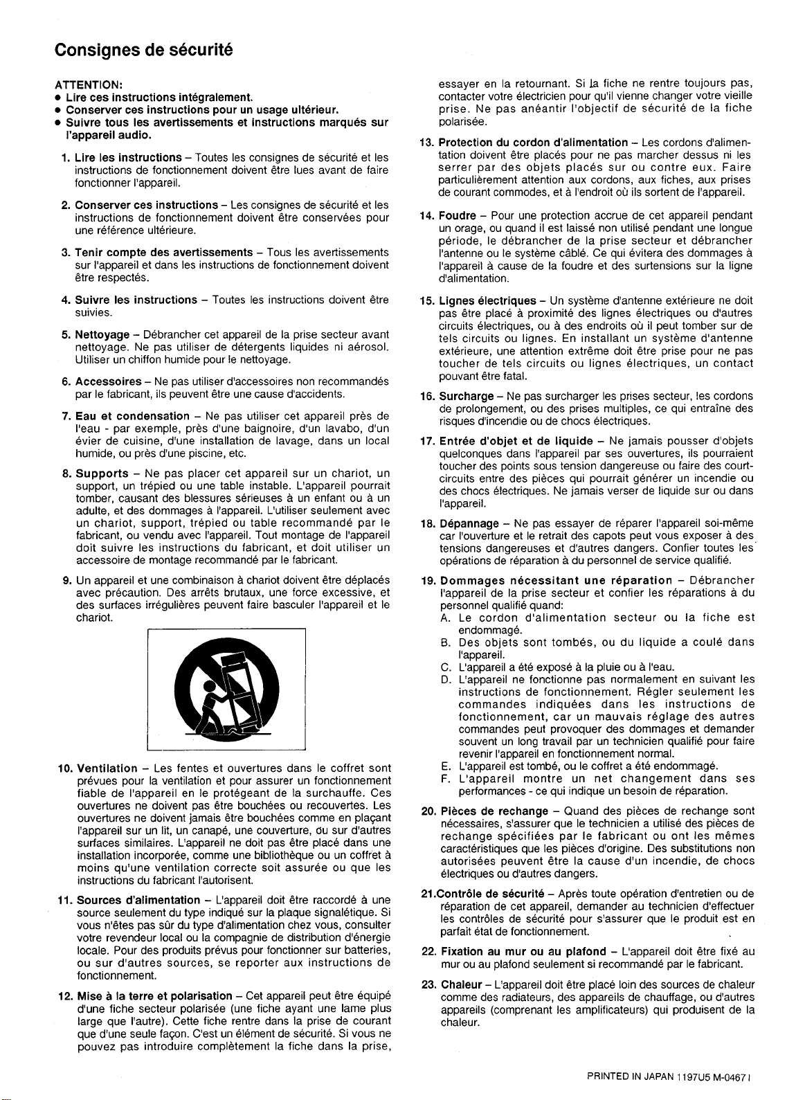
8) Accessories — Do not place this product on an unstable cart, stand,
tripod, bracket, or table. The product may fall, causing serious injury to a
child or adult, and serious damage to the product. Use only with a cart,
stand, tripod, bracket, or table recommended by the manufacturer, or sold
with the product. Any mounting of the product should follow the manufacturer’s instructions, and should use a mounting accessory recommended by
the manufacturer.
9) A product and cart combination should be moved with care. Quick
stops, excessive force, and uneven surfaces may cause the product and cart
combination to overturn.
10) Ventilation — Slots and openings in the cabinet are provided for
ventilation and to ensure reliable operation of the product and to protect it
from overheating, and these openings must not be blocked or covered. The
openings should never be blocked by placing the product on a bed, sofa,
rug, or other similar surface. This product should not be placed in a builtin installation such as a bookcase or rack unless proper ventilation is provided or the manufacturer’s instructions have been adhered to.
11) Power Sources — This product should be operated only from the
type of power source indicated on the marking label. If you are not sure of
the type of power supply to your home, consult your product dealer or
local power company. For products intended to operate from battery
power, or other sources, refer to the operating instructions.
12) Grounding or Polarization — This product may be equipped with
a polarized alternating-current line plug (a plug having one blade wider
than the other). This plug will fit into the power outlet only one way. This
is a safety feature. If you are unable to insert the plug fully into the outlet,
try reversing the plug. If the plug should still fail to fit, contact your electrician to replace your obsolete outlet. Do not defeat the safety purpose of
the polarized plug.
13) Power-Cord Protection — Power-supply cords should be routed
so that they are not likely to be walked on or pinched by items placed upon
or against them, paying particular attention to cords at plugs, convenience
receptacles, and the point where they exit from the product.
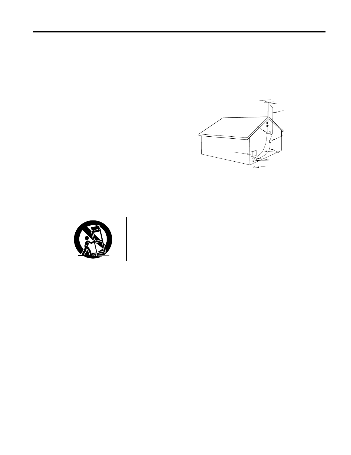
14) Outdoor Antenna Grounding — If an outside antenna or cable
system is connected to the product, be sure the antenna or cable system is
grounded so as to provide some protection against voltage surges and
built-up static charges. Article 810 of the National Electrical Code,
ANSI/NFPA 70, provides information with regard to proper grounding of
the mast and supporting structure, grounding of the lead-in wire to an
antenna discharge unit, size of grounding conductors, location of antennadischarge unit, connection to grounding electrodes, and requirements for
the grounding electrode.
"Note to CATV system installer:
This reminder is provided to call the CATV system installer’s attention to
Section 820-40 of the NEC which provides guidelines for proper grounding and, in particular, specifies that the cable ground shall be connected to
the grounding system of the building, as close to the point of cable entry as
practical.
Example of Antenna Grounding as per
National Electrical Code, ANSI/NFPA 70
ANTENNA
LEAD IN
WIRE
GROUND
CLAMP
ANTENNA
DISCHARGE UNIT
(NEC SECTION 810-20)
ELECTRIC
SERVICE
EQUIPMENT
NEC - NATIONAL ELECTRICAL CODE
GROUNDING CONDUCTORS
(NEC SECTION 810-21)
GROUND CLAMPS
POWER SERVICE GROUNDING
ELECTRODE SYSTEM
(NEC ART 250. PART H)
15) Lightning — For added protection for this product during a lightning
storm, or when it is left unattended and unused for long periods of time,
unplug it from the wall outlet and disconnect the antenna or cable system.
This will prevent damage to the product due to lightning and power-line
surges.
16) Power Lines — An outside antenna system should not be located in
the vicinity of overhead power lines or other electric light or power circuits, or where it can fall into such power lines or circuits. When installing
an outside antenna system, extreme care should be taken to keep from
touching such power lines or circuits as contact with them might be fatal.
17) Overloading — Do not overload wall outlets, extension cords, or
integral convenience receptacles as this can result in risk of fire or electric
shock.
18) Object and Liquid Entry — Never push objects of any kind into
this product through openings as they may touch dangerous voltage points
or short-out parts that could result in a fire or electric shock. Never spill
liquid of any kind on the product.
19) Servicing — Do not attempt to service this product yourself as opening or removing covers may expose you to dangerous voltage or other hazards. Refer all servicing to qualified service personnel.
20) Damage Requiring Service — Unplug this product from the wall
outlet and refer servicing to qualified service personnel under the following conditions:
a) when the power-supply cord or plug is damaged.
b) if liquid has been spilled, or objects have fallen into the product.
c) if the product has been exposed to rain or water.
d) if the product does not operate normally by following the operating
instructions. Adjust only those controls that are covered by the operating
instructions as an improper adjustment of other controls may result in
damage and will often require extensive work by a qualified technician to
restore the product to its normal operation.
e) if the product has been dropped or damaged in any way.
f ) when the product exhibits a distinct change in performance _ this indi-
cates a need for service.
21) Replacement Parts — When replacement parts are required, be
sure the service technician has used replacement parts specified by the
manufacturer or have the same characteristics as the original part.
Unauthorized substitutions may result in fire, electric shock, or other hazards.
22) Safety Check — Upon completion of any service or repairs to this
product, ask the service technician to perform safety checks to determine
that the product is in proper operating condition.
23) Wall or Ceiling Mounting — The product should be mounted to a
wall or ceiling only as recommended by the manufacturer.
24) Heat — The product should be situated away from heat sources such
as radiators, heat registers, stoves, or other products (including amplifiers)
that produce heat.
3


»
MMR-8
TEAC CORPORATION 3-7-3, Nakacho, Musashino-shi, Tokyo 180, Japan Phone: (0422) 52-5082
TEAC AMERICA, INC. 7733 Telegraph Road, Montebello, California 90640 Phone: (213) 726-0303
TEAC CANADA LTD. 5939 Wallace Street, Mississauga, Ontario L4Z 1Z8, Canada Phone: 905-890-8008 Facsimile: 905-890-9888
TEAC MEXICO, S.A. De C.V Privada De Corina, No.18, Colonia Del Carmen Coyoacon, Mexico DF 04100 Phone: 5-658-1943
TEAC UK LIMITED 5 Marlin House, Marlins Meadow, The Croxley Centre, Watford, Herts. WD1 8YA, U.K. Phone: 01923-819699
TEAC DEUTSCHLAND GmbH Bahnstrasse 12, 65205 Wiesbaden-Erbenheim, Germany Phone: 0611-71580
TEAC FRANCE S. A. 17 Rue Alexis-de-Tocqueville, CE 005 92182 Antony Cedex, France Phone: (01) 42.37.01.02
TEAC BELGIUM NV/SA P.A. TEAC Nederland BV, Perkinsbaan 11a, 3439 ND Nieuwegein, Netherlands Phone: 0031-30-6048115
TEAC NEDERLAND BV Perkinsbaan 11a, 3439 ND Nieuwegein, Netherlands Phone: 030-6030229
TEAC AUSTRALIA PTY., LTD.
A.C.N. 005 408 462
TEAC ITALIANA S.p.A. Via C. Cantù 5, 20092 Cinisello Balsamo, Milano, Italy Phone: 02-66010500
106 Bay Street, Port Melbourne, Victoria 3207, Australia Phone: (03) 9644-2442

5
Tascam MMR-8 Owner’s Manual
Chapter 1 General Information ........................................................................ 9
MMR-8 Introduction.........................................................................................................................9
Hardware Overview ........................................................................................................................10
Functional Overview........................................................................................................................12
System Specifications.......................................................................................................................15
Chapter 2 Installation.......................................................................................17
MMR-8 Materials Kit Box ..............................................................................................................17
General Guidelines ..........................................................................................................................18
Mounting Rack Ears .................................................................................................................................... 18
Installing Multiple MMR Units....................................................................................................................19
AC Mains and Grounding Considerations..................................................................................................... 20
Audio Cables ....................................................................................................................................20
MMR-8 Back Panel Connections....................................................................................................21
Audio Connections ...................................................................................................................................... 22
Analog In/Out Connections ...................................................................................................................... 22
Digital In/Out Connections ...................................................................................................................... 22
Monitoring Connections...........................................................................................................................22
Timecode and Video Reference Signals........................................................................................................ 23
Video In/Out............................................................................................................................................23
SMPTE/EBU Time Code In/Out.............................................................................................................. 23
VITC In................................................................................................................................................... 23
Biphase Connections................................................................................................................................24
Digital Audio Sample Reference Connections .............................................................................................. 24
Word Clock............................................................................................................................................. 24
AES/EBU Sample Rate............................................................................................................................ 24
MIDI Connections .......................................................................................................................................25
External Controllers & Bus Connections ......................................................................................................25
Lynx Bus / KCU Connection ................................................................................................................... 25
MMR Sync Bus Connections...................................................................................................................25
Serial Transport Connection..................................................................................................................... 26
Serial Editor Connection..........................................................................................................................26
Parallel Transport ....................................................................................................................................26
Parallel Tracks.........................................................................................................................................26
Connecting External SCSI Media...................................................................................................26
Remote Controllers for the Tascam MMR-8..................................................................................27
Powering Up the System..................................................................................................................28
Verifying MMR-8 Installation.........................................................................................................28
Software Updates ......................................................................................................................................... 29
Factory Default Settings..................................................................................................................30
Testing Your Installation.................................................................................................................30
MMR-8 Tascam MMR-8 Owner’s Manual • Table of Contents

6
Chapter 3 MMR-8 Operation...........................................................................33
MMR-8 Keys & Definitions.............................................................................................................33
MMR-8 Front Panel .........................................................................................................................35
Front Panel Indicators, Switches, and Displays..............................................................................37
LED Indicators............................................................................................................................................ 37
Configuration Settings............................................................................................................................. 37
Active Mode/Key Indicators.................................................................................................................... 37
Track Status and Metering....................................................................................................................... 37
Meter LEDs ............................................................................................................................................ 37
Machine Status LEDs.............................................................................................................................. 38
Liquid Crystal Display (LCD)...................................................................................................................... 39
Normal State Display............................................................................................................................... 39
Setup State Display.................................................................................................................................. 40
View Track State Display........................................................................................................................ 40
Slip Track State Display .......................................................................................................................... 41
Load Track State Display......................................................................................................................... 41
Backup State Display............................................................................................................................... 42
Verify State Display ................................................................................................................................ 42
Error State Display.................................................................................................................................. 42
Front Panel Key Groups..................................................................................................................43
Transport Group.......................................................................................................................................... 43
Setup and Wheel Group............................................................................................................................... 44
Wheel.......................................................................................................................................................... 46
Track Group................................................................................................................................................ 46
Keypad Group............................................................................................................................................. 55
Basic Operation................................................................................................................................61
Loading and Mounting Drives...................................................................................................................... 61
Loading a Project, Session, or Composition ................................................................................................. 62
Loading Individual Tracks........................................................................................................................... 62
Viewing Tracks........................................................................................................................................... 63
Unloading Tracks ........................................................................................................................................ 63
Deleting Tracks from the Disk..................................................................................................................... 63
Recording a New Project .................................................................................................................63
Using Registers.................................................................................................................................64
Recalling Registers...................................................................................................................................... 64
Capturing the Current Time Code ................................................................................................................ 64
Trimming Time Code Values....................................................................................................................... 65
Using the Entry Register.............................................................................................................................. 65
Local & Studio Monitoring..............................................................................................................66
Headphone Volume (LEVEL)...................................................................................................................... 66
Headphone Jack (PHONES) ........................................................................................................................ 66
Chapter 4 MMR-8 Setup Menus......................................................................67
The Setup State & the Setup Menus................................................................................................67
Setup Operation ...............................................................................................................................68
Setup Menu Chart............................................................................................................................69
Tascam MMR-8 Owner’s Manual • Table of Contents MMR-8

7
Setup Menu Details..........................................................................................................................73
Control Mode...............................................................................................................................................73
Local/Bus................................................................................................................................................73
Time Code Chase.....................................................................................................................................73
Biphase Chase .........................................................................................................................................73
Biphase Transport.................................................................................................................................... 73
Serial Transport....................................................................................................................................... 74
Editor......................................................................................................................................................74
Varispeed ................................................................................................................................................74
User Settings................................................................................................................................................74
The Lynx Bus ..............................................................................................................................................75
Transport Control .................................................................................................................................... 75
Track Record Arm/Select ......................................................................................................................... 75
Head/Tail ................................................................................................................................................ 75
Slip Track/Region....................................................................................................................................75
Prev/Next ................................................................................................................................................76
Undo/Redo ..............................................................................................................................................76
Clear/Paste .............................................................................................................................................. 76
Record Mode...............................................................................................................................................77
Non-Destructive.......................................................................................................................................77
Auto Cleanup .......................................................................................................................................... 77
Tape Mode ..............................................................................................................................................77
The MMR Bus.............................................................................................................................................78
Chapter 5 MMR-8 System Applications..........................................................79
Film Post Production.......................................................................................................................79
The MMR-8 As Master................................................................................................................................80
Biphase Setup Menus ................................................................................................................................... 80
MMR-8 Film Connections ........................................................................................................................... 82
Video Post Production.....................................................................................................................82
The Lynx Bus ..............................................................................................................................................82
Chapter 6 Maintenance & Service...................................................................83
System Input Level Calibration Using the Meter LEDs.................................................................83
MMR Input and Output Level Calibrations................................................................................................... 83
MOC Calibration Procedure.........................................................................................................................84
MIC Calibration Procedure .......................................................................................................................... 85
Adding External Drives to the System............................................................................................86
Formatting Disks .............................................................................................................................86
Using Removable Media..................................................................................................................86
Chapter 7 Technical Support...........................................................................87
MMR-8 System Software ................................................................................................................87
Appendix A: Control Panel Command Summary..........................................................................89
Transport Group ......................................................................................................................................89
Setup and Wheel Group...........................................................................................................................89
Keypad keys............................................................................................................................................90
Track Select Keys.................................................................................................................................... 92
Appendix B: TASCAM MMR-8 Drive Compatibility Chart.........................................................93
Appendix C: WaveFrame Compatibility........................................................................................95
MMR-8 Tascam MMR-8 Owner’s Manual • Table of Contents

8
Appendix D: MMR-8 Cable Information........................................................................................97
PARALLEL TRACKS and PARALLEL TRANSPORT Connector.............................................................. 97
MIDI IN/THRU/OUT Connector pinout ...................................................................................................... 98
LYNX (Remote Controller) Connector pinout .............................................................................................. 98
EDITOR Connector pinout .......................................................................................................................... 98
TRANSPORT (Sony 9-pin) Connector pinout .............................................................................................. 99
ANALOG INPUT & OUTPUT Connectors pinouts ....................................................................................100
BIPH (Biphase) Connectors pinout .............................................................................................................100
DIO (AES/EBU Digital Audio) Connector pinout .......................................................................................101
SYNC (MMR-Bus) Connector pinout.........................................................................................................101
TIMECODE IN Connector .........................................................................................................................102
TIMECODE OUT Connector .....................................................................................................................102
WORD CLOCK IN Connector ...................................................................................................................102
WORD CLOCK OUT Connector................................................................................................................102
VIDEO IN/OUT Connector........................................................................................................................102
VITC IN Connector....................................................................................................................................103
SERIAL CONNECTORS...........................................................................................................................103
SCSI Connector..........................................................................................................................................103
PRX Connector ..........................................................................................................................................103
Appendix E: MMR-8 Glossary......................................................................................................105
Index...............................................................................................................................................111
MMR-8 Owner’s Manual Version 1.20CE
Tascam MMR-8 Owner’s Manual • Table of Contents MMR-8
9
Chapter 1 General Information
This chapter presents the main features and capabilities of the MMR-8 hardware and a functional
overview of its Panel/Display states. MMR-8 product specifications are also included.
MMR-8 Introduction
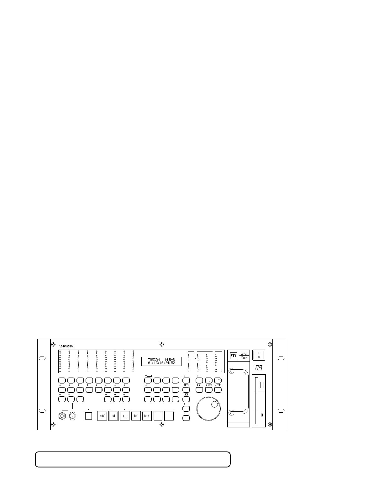
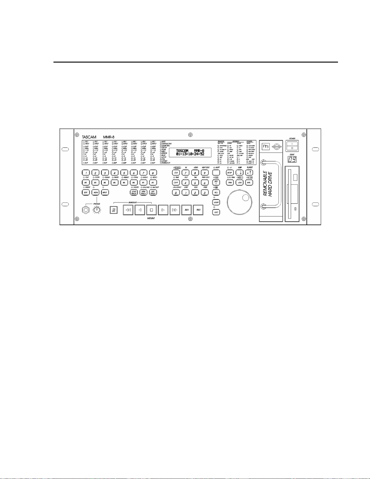
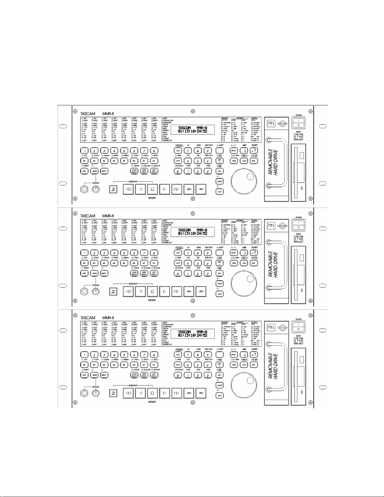
Figure 1-1. MMR-8 Front View
The MMR-8 is a non-linear digital replacement for the analog or digital tape machines found in recording
studios and broadcast facilities, and for magnetic film dubbers found in film and video post-production
facilities. The MMR-8 can play back and record eight tracks of material from one or more SCSI hard
drives or other removable media. Each MMR-8 can record onto a single removable SCSI hard drive, or
play back from multiple SCSI disk drives of various types. Playback can be in exact or track-slipped
synchronization to industry-standard film, video, and audio devices, whether mechanical tape-based or
hard drive-based.
Audio files recorded on the MMR-8 consist of selectable linear 16-bit or linear 24-bit words at sample
rates of 48.0 kHz or 44.1 kHz, each modifiable to a pull-up or pull-down level, including conversion
between PAL, film, and video, making fourteen total discrete sampling rates. The analog I/O section uses
balanced +4 dBu analog connections on DB-25 connectors that are pin-compatible with the Tascam DA88 and may use the same cables. The DIO (Digital I/O) card allows direct connection of the MMR to
standard AES/EBU digital audio inputs and outputs for direct digital recording and playback. The digital
I/O connector can use a standard DA-88 cable to provide four stereo AES inputs and four stereo AES
outputs. Any digital input can be selected as the sample clock reference source. Additionally, any one of
the four digital input signal pairs can be selected for routing through a sample rate converter.
Tascam MMR-8 Owner’s Manual • Chapter 1 • General Information MMR-8

10
The MMR-8 will directly play back material created on Digidesign Pro Tools or WaveFrame digital
audio workstations, as well as OMF Compositions which reference Sound Designer II audio media files.
The disk drive or drives containing edited Session, Project, or OMF files are simply “unplugged” from
the workstation and then “hot-plugged” into the MMR-8, using the standard internal Kingston hard drive
carrier, or otherwise connected to the MMR-8’s external SCSI port. Once the drive(s) are mounted by the
MMR-8, tracks from one or more projects may be loaded as required for the mix session. Sound files of
the same or different audio formats may thus be played back simultaneously from one or more drives.
When the MMR-8 is turned on for the first time, the system default operating parameters are installed,
and the machine is placed into the Normal state (see the Functional Overview below). Users can also save
up to ten settings files that have MMR-8 parameters “customized” or set for a particular application.
These settings files are stored on the internal hard drive so that they can be used to instantly reconfigure
the MMR-8 between mix sessions. The MMR-8’s operating parameters can be manually changed before
or even during a mix session, through menu selections. Optional password protection may be used to
prevent some parameters from being changed inadvertently.
Hardware Overview
The MMR-8 comes standard with one removable Kingston drive carrier. The Kingston carrier can hold a
standard SCSI drive for recording and playback of audio tracks. An internal IDE hard drive holds the
operating system, the MMR-8 software, and the parameter settings files. Additional external SCSI drives
can be connected and (after power-up) accessed by the MMR-8. This eliminates having to pre-combine
tracks from multiple drives onto a single drive. A list of approved media drives is given in Appendix B.
The MMR-8 is based on a standard Intel Pentium™ processor-based PC motherboard, with integral PCI
and ISA bus slots running under an industry-standard operating system. The MMR-8 DSP,
synchronization, and audio interface boards plug directly into this PC motherboard. There is a Lithium
battery #CR2032 for the CMOS circuit on the motherboard. Caution: Battery May Explode if
Mistreated. Do Not Recharge, Disassemble or Dispose of in Fire. The MIC (MMR-8 analog-to-digital
Input Converter) and MOC (MMR-8 digital-to-analog Output Converter) boards are in their own shielded
cage, connected to the AIO (Analog I/O) card via ribbon cables. The PRX (DSP) card performs the audio
processing for the MMR-8. A standard Symbios SCSI-2 controller card also plugs into the PCI bus. The
Sync card, the UI/B (User Interface/Biphase) card, the AIO (analog I/O) card, and the DIO (AES/EBU
digital I/O) card are all plugged into the ISA bus. The Biphase Operations Board (BOB) occupies a slot
on the back panel to provide connections for the system’s four Biphase inputs and one Biphase output. It
is attached to the UI/B card via a ribbon cable and is not plugged into a slot.
Very high quality 20-bit converters on all analog inputs and outputs assure excellent audio fidelity. The
MMR-8 uses 24-bit internal digital resolution for all digital audio processing. Recorded audio is stored in
standard linear 16-bit or 24-bit sound files. The MMR-8 can read StudioFrame or WaveFrame sound files
as well as Sound Designer II files, AIFC files, and .WAV files, all in either 16 or 24-bit resolution.
The MMR-8 front panel contains 45 soft-touch keys with most of the common dubber and audio playback
functions available through one or two keystrokes. There are also seven large illuminated motion control
buttons (Play, Stop, FF, Rew, Reverse Play, Record, Rehearse) for track playback and “play head”
locating, and an Online button for setting the MMR-8 offline (as a local machine) or online (as a
synchronized slave or a master machine). When the MMR-8 is the master and is online, then any number
of external SMPTE/EBU, MTC or biphase devices will follow the MMR-8. When the MMR-8 is set as a
slave, it can chase time code, biphase, a TimeLine Lynx™ module, or another MMR-8.
MMR-8 Tascam MMR-8 Owner’s Manual • Chapter 1 • General Information

11
A 40-character (two line by 20-character) LCD (Liquid Crystal Display) serves as the MMR-8 status and
control text window. The top line typically shows the machine status and current time code or feet/frames
location, while the bottom line shows various time code registers (memory, slip. etc.) and accepts input
from the front panel. The entire display may also alert the operator to any machine or user error
conditions. It can be scrolled horizontally or vertically, using the Wheel or arrow keys, for entering
Panel/Display state and setup information, or for finding and loading tracks.
As with other 8-track recorders, there are dedicated front panel LED peak meters that always display
monitor level information for the track outputs whether in audio input or playback. Each meter contains
seven green, yellow and red LEDs plus a CLIP/Hold LED for easy at-a-glance level monitoring. An
additional 74 status LEDs instantly identify current synchronization modes, bus control modes, sample
and frame reference settings, record format settings, transport status, and front panel input status.
The MMR-8 rear panel contains all the audio and synchronization connections. To minimize connector
footprint, female DB-25 connectors are used for the audio connections. The eight analog audio inputs are
on one female DB-25 and the eight analog audio outputs are on another female DB-25. Each analog
connector mounts on a separate card within the chassis, and is labeled Input or Output. The connectors are
pin-compatible with the Tascam DA-88 analog audio connector.
The DIO card allows direct digital audio transfers into and out of the MMR-8. Because it uses standard
AES/EBU digital signal conventions, there are four stereo digital inputs and four stereo digital outputs
with odd-even track pairs. Tracks 1+2 are on the first AES/EBU connection, tracks 3+4 on the second
AES/EBU connection, and so on. All eight tracks (four pairs of in and out) are on a single female DB-25
connector. Any of the digital inputs can serve as a sample rate reference and any of the input pairs can
also be routed through an on-board sample rate converter. Note that this connector carries AES/EBU
digital signals and is NOT pin-compatible with the Tascam DA-88 TDIF digital audio format connector.
Built-in biphase control allows the MMR-8 to automatically lock to and chase biphase devices
without having to use an external biphase to SMPTE/EBU adapter. Up to four biphase input
signals can be simultaneously connected to the MMR-8. The active biphase input is determined by menu
selection. A biphase output allows the MMR-8 to directly control a single biphase bus. Software setup
parameters allow various biphase device limitations to be imposed upon the MMR-8 (speed of fast
forward and rewind, ramp up and stop speed, etc.). Not intended for public telecommunications
network connection.
Video post-production work can be done with any industry-standard playback device. The MMR-8
supports VITC, SMPTE/EBU LTC time code, Word Clock, house sync, MTC, and P2-bus (Sony 9-pin)
protocols.
The Tascam MM-RC is a dedicated remote control unit designed specially for use with the MMR-8 and
the MMP-16 sixteen-channel player unit. It connects directly to the UI/B board on the MMR back panel
and allows control of any combination of up to 100 MMR-8 or MMP-16 units.
The TimeLine Lynx Keyboard Control Unit (KCU) can function as a remote controller for up to six
MMR-8s or other transports as the MMR-8 contains an integrated Lynx-2 synchronizer. The Lynx KCU
900 software includes special MMR support for some editing and event slip commands. Other remote
controllers can also be used for controlling the transport and track arm functions of the MMR-8 through
the two Parallel Remote ports or the Editor Remote port.
Tascam MMR-8 Owner’s Manual • Chapter 1 • General Information MMR-8

12
Functional Overview
The MMR-8 operates in any of eight different Panel/Display states (simply referred to as “states” for
convenience). These states are distinguished by the nature of the information displayed in the LCD
window and by which keys are functionally available while in that state. These MMR-8 Panel/Display
states are described here.
Normal state is the default Panel/Display state on power-up. In this state, the LCD shows the current
system play time in the top of the display, and shows the active register (last requested register or function
time) in the bottom of the display. All keys are active while in this state, and will respond by performing
an action, accessing a register, or changing to the state written on the key. Shifted key functions are also
available by first pressing the SHIFT key, then pressing the key which corresponds to the desired shifted
function. Once the SHIFT key is selected, pressing the appropriate key to activate the desired shifted
function completes the SHIFT operation. The SHIFT state can be cancelled by pressing SHIFT again, or
by pressing CLR, to return the system to normal key selection.
Pressing the SETUP key activates the Setup state. This state gives access to the system setup menus,
where most of the operating parameters of the MMR-8 can be altered. Some parameters are changeable
only under certain operating conditions (non-record, stopped, etc.), although all are viewable at any time
in the Setup state. Once in the Setup state, you may return to the Normal state by pressing the SETUP key
again, or by pressing CLR.
There are three types of Panel/Display states that deal with MMR-8 track operations. These are Load
Track, View Track, and Slip Track. Pressing the LOAD TRACK, TRACK, or SLIP keys puts the
MMR-8 into one of these Track states. The SEL keys for each MMR track are used in conjunction with
these keys to identify the specific track to be loaded, viewed, or slipped.
There are also three keys to the left of the Track state keys labeled EDIT, MON, and INPUT. These keys
do not change the state of the MMR display, but are used to determine what status is being indicated for
each MMR track by the track selection LEDs when the SEL keys are pressed while in the Normal state of
operation. One of these keys is always active as the current Track Mode. Since these keys function along
with the Track state keys to identify the function being specified by the SEL keys, the entire group of six
keys (EDIT, MON, INPUT, LOAD TRACK, TRACK, and SLIP) are also referred to as the Track Mode
keys.
The Track states supersede the Normal state since they change the display and make certain keys
unavailable until the Track state is exited or cleared. To exit a Track state and return the MMR-8 to the
Normal state, it is necessary to either complete the selected track operation (by pressing STO to load a
Project, for example), or press the selected Track state key again, or press the CLR key to cancel the
operation. After exiting a Track state, the system will return to the Normal state and the last selected
Track Mode (EDIT, MON, INPUT).
Pressing the LOAD TRACK key activates the Load Track state. This state allows for loading
WaveFrame projects, OMF Compositions, or Pro Tools Session files from any mounted disk volume.
This state also allows loading of individual tracks from a Project, Composition, or Session (hence the
name of this key and state), and moving of tracks from one MMR channel to another. The shifted function
of LOAD TRACK allows for deleting WaveFrame Projects or Tracks. The MMR-8 software does not
currently allow OMF Compositions and Pro Tools Session Files to be deleted.
MMR-8 Tascam MMR-8 Owner’s Manual • Chapter 1 • General Information

13
The MMR Backup state is accessed via the Load Track state by pressing SHIFT+SLIP after choosing
(scrolling to) the desired Project while in the LOAD TRACK state. This state is similar to the Setup state
in that it has two menu choices which are accessed by using the Up/Down arrow keys or the Wheel. The
key choices available in the Backup state are the same as those in the Setup state, hence it exists at the
same level of the hierarchy of panel/display states as the Setup state.
Pressing the TRACK key activates the View Track state. This state allows for viewing the names of
loaded tracks, and unloading of tracks (the shifted function of the TRACK key) from the loaded track list.
Pressing the SLIP key activates the Slip Track state. This state allows for slipping one or more of the
already loaded tracks in time.
Verify state supersedes the Normal and Track states. The two most common Verify state functions are
confirmation (a Yes/No answer is required from the user) and password entry (a password must be
entered to complete the action request). Both of these requests override most other actions or do not allow
access to the Normal, Setup, or Track states until they are cleared or a valid response is entered. Verify
state, when cleared, usually drops the MMR-8 back into the previously active state.
Error state is the final level in the hierarchy of Panel/Display states. In this state, the ERROR status light
flashes and the user is asked to clear a condition by pressing the CLR key, or if that is impossible (as in
the case of a fatal error), to note the error information and possibly take some extraordinary action (such
as re-starting the MMR-8). Until the Error state is cleared, or a valid response is entered, access to the
Normal, Setup, or Track states is not allowed. The Error state, when cleared, may drop to another state, or
to any appropriate condition—depending on the type and severity of the error.
These states are hierarchical in the sense that some require a response or they require a state to be cleared
before certain keys or other states can be accessed. The Normal state is at the base of the hierarchy
because it is the default on startup and can always be accessed from any other state or by pressing the
CLR key as many times as is necessary to clear any other state. The track record arm function and the
transport keys can be accessed directly from any state, so the MMR can always record and playback,
regardless of what other functions or states are being accessed. The following diagram illustrates the
hierarchical relationship between the various states, based on the number of choices available from each
state.
Tascam MMR-8 Owner’s Manual • Chapter 1 • General Information MMR-8
14
LLo
o
o
a
a
a
d
d
d
,
,
,
V
V
V
i
i
i
e
e
e
w
w
w
,
,
,
S
S
S
l
l
l
i
i
i
p
p
p
T
T
T
r
r
r
a
a
a
c
c
c
k
k
k
V
V
Vee
err
rii
iff
fyy
yEE
Err
rrr
roo
orr
r
S
e
t
u
p
,
B
a
c
k
u
S
e
t
u
p
,
S
e
N
N
N
Figure 1-3. MMR-8 Panel/Display State Hierarchy
STATE LCD WINDOW DISPLAY COMMENT
NORMAL
SETUP
LOAD TRACK
VIEW TRACK
SLIP TRACK
VERIFY
ERROR
BACKUP
Shows current play head time on top and
selected time register on bottom of display.
Shows setup menus and parameter choices
for each menu item.
Shows disk directory list of projects,
compositions, sessions, and their tracks.
Shows other levels for WaveFrame projects.
Backup state can be accessed only while
viewing name of project while in this state.
Shows the name of each loaded track. Use
wheel, arrows, or press appropriate SEL key
to choose which track to view.
Shows Current Play position on top, Slip
register value for each track below, allows
for slipping tracks in time. All SEL keys
have a SLIP register, so numbers can be
stored, recalled, or cleared directly.
Asks for a response (usually requires
pressing Yes or No) to clear state and return
to previous state.
Shows Error message, usually requires
pressing CLR to clear and return to previous
state.
Menu with two choices: BeginBackup to
(device#) or TapeMode Convert to (device#).
Only currently mounted devices will appear
as choices.
B
t
u
p
,
B
o
r
m
a
o
r
m
a
o
r
m
a
p
a
c
k
u
p
a
c
k
u
p
l
l
l
Default at startup. Allows
direct access to SETUP and
TRACK states, all keys
functional.
Press SETUP to enter state,
press TRIM to view
parameters.
Press LOAD TRACK once to
see Project level, again to see
successive levels (tracks).
Press SHIFT+SLIP while in
LOAD TRACK to enter
Backup state.
Press TRACK to enter state,
SHIFT+TRACK to unload
track.
Press SLIP to enter state, use
wheel or arrows to change
value, or enter TC value on
keypad & press STO then SEL
to enter number directly.
Disallows most key entry or
switching to other states until
response is made.
Disallows most key entry or
switching to other states until
condition is cleared.
Accessed only via LOAD
TRACK state. Use Up/Down
arrows or wheel to choose
Backup style, press STO to
begin backup process.
Figure 1-4. MMR-8 Panel/Display State Chart
MMR-8 Tascam MMR-8 Owner’s Manual • Chapter 1 • General Information

15
System Specifications
Analog Input and Output Level:+4 dBu balanced, +24 dBu clip, nominal levels trim pot adjustable
Headroom:20 dB above nominal input level
Analog Input / Output Impedance:10k, balanced / <75 ohms, balanced
Input / Output Adjustment Range: +10 dBu - +25 dBu, clipping / +18 dBu - +25 dBu, clipping
THD+N:<.004 % @ 1 kHz, @ clip level -0.5 dB
Dynamic range:>104 dB (10 Hz - 22 kHz, with A-weighted filter), including Record.
S/N ratio:>108 dB (10 Hz - 22 kHz, with A-weighted filter)
Crosstalk:<-85 dB (between any channels, 20 Hz - 20 kHz)
Frequency Response:20 Hz - 20 kHz ±0.1 dB
Digital Conversion / Quantization:20-bit ADC and 20-bit DAC conversion
Sample length, Recording:16-bit, linear or 24-bit, linear
Sample Length, Internal: 24 bit
Timing Reference sources:Internal, Internal Varispeed, Follow time code in, Follow biphase signal input
(any one of four inputs), Video (either NTSC or PAL), AES/EBU digital clock input (optional), Word
clock input, MMR bus, Lynx bus
Internal Sample Rates in Hz: 42294 (44x23/25), 42336 (44x24/25), 44056 (44100-), 44100, 44144
(44100+), 45938 (44x25/24), 45983 (44x25/23), 46034 (48x23/25), 46080 (48x24/25), 47952 (48000-),
48000, 48048, (48000+),50000 (48x25/24)50050 (48x25/23)
External Sample rates:32 kHz - 51 kHz (via external sync input)
Time Code Type & Rate:30 Non drop frame (NDF) @ 30 frames per second
30 Drop frame (DF) @ 30 frames per second
PAL @ 25 frames per second (PAL default setting)
Film @ 24 frames per second
NTSC @ 29.97 frames per second NDF (NTSC default setting)
29.97 Drop frame(DF) @ 29.97 frames per second
Display Modes:SMPTE/EBU time code, with or without subframes
Feet & Frames, with or without subframes
Time Code Memories:ten (numbered 0 - 9)
Time Code Registers:IN (punch in point)
OUT (punch out point)
HEAD (jump to beginning of project)
TAIL (jump to end of project)
NEXT EDIT (jump to next track edit)
PREVIOUS EDIT (jump to last track edit)
TIME (for establishing 0 film feet and frames referenced to time code)
LYNX SYNC (Lynx bus offset time calculation)
OFFSET (Offset time for Lynx bus and time code chase)
READER (time code from LTC, VITC or Serial inputs)
FREE (available record time on current disk) lskdf
Tascam MMR-8 Owner’s Manual • Chapter 1 • General Information MMR-8

16
Electrical Ratings:
115 VAC @ 2A, 50-60Hz 230 W Max
-OR-
230 VAC @ 1A, 50-60Hz 230 W Max
Nominal temperature should be 41 to 95 degrees Fahrenheit (5 to 35 degrees Centigrade).
Relative humidity should be 30 to 90% (non-condensing)
Analog input/output is 12.28 VRMS Max
Weight is approximately 37 Pounds ( 16.78 Kilograms) with a hard disk loaded.
MMR-8 Tascam MMR-8 Owner’s Manual • Chapter 1 • General Information

17
Chapter 2 Installation
This chapter covers the physical installation of the Tascam MMR-8 as either a stand-alone
recording/playback system or as part of a larger, multiple unit digital dubber system. Descriptions are
given of the various connectors on the MMR back panel. Both general installation procedures and specific
application installations are covered.
MMR-8 Materials Kit Box
Before connecting the MMR-8 hardware to your audio system and to your video or film playback
devices, verify that you have all the equipment required to complete the task. The following equipment is
included in the MMR Materials Kit Box:
Rack Ears Kit For rack mount installation, the two rack ears may be attached to the front sides of
the MMR-8 chassis using the six 8-32 x 3/8” Phillips head screws included in the
MMR-8 materials kit. The MMR-8 can be used without the rack ears for desktop
applications.
MMR Bus A three-foot sync cable for synchronizing the operation of multiple MMR
Sync Cable 8’s together via the rear panel MMR bus connectors.
RS422 Cable A 9-pin RS-422 (232) cable for attaching the COM port to a terminal for running
field diagnostics. Also may be used for 9-pin serial connections.
Kingston One Kingston removable drive carrier is included with the system. This
Removable carrier allows drives to be hot-swapped while the system is powered on. It
SCSI Drive is necessary to install a SCSI drive from the list of approved drives into the
Carrier Instructions Kingston carrier before you can record or playback audio using the carrier with the
MMR-8. The instruction manual for installing drives in the Kingston carrier is in
the MMR-8 materials kit.
AC Power Cord A six-foot (1.83 Meter) IEC AC Mains cordset is included with the MMR-8. The
mains connector for 115 VAC systems is USA standard. A six-foot (1.83 Meter)
AC Mains cordset for use in Europe, proper for the country of use will be supplied
by your TASCAM dealer. Attach the AC connector in accordance with local
requirements.
Toolkit As a convenience, a small toolkit consisting of a “tweaker” and a small screwdriver
is included in the zip-locked plastic bag in the materials kit. The “tweaker” may be
used for making any necessary adjustments to the analog trim pots on the analog
audio output board.
MMR-8 Tascam MMR-8 Owner’s Manual • Chapter 2 • Installation

General Guidelines
Mounting Rack Ears
The MMR-8 is a self-contained eight channel digital playback and recording device designed to be
mounted in a standard 19” (48.26 cm) IEC equipment rack in either the mix studio or a dedicated machine
room in a professional audio recording facility. As such, each MMR-8 is housed in a steel chassis 19inches (48.26 cm) wide by 17 ¼ inches (43.81 cm) deep by 7-inches (17.78 cm) tall. Each MMR-8
requires 5U (7-inches or 17.78 cm) of rack space.
Integral rack ears are provided with the chassis. If the unit is not rack-mounted, the rack ears do not need
to be installed onto the MMR-8 chassis. For rack mounting, install one rack ear to the front of each side of
the MMR-8 (three Phillips screws per side are supplied for fastening the rack ears to the chassis).
Figure 2-1. Rack Ear Installation
18 Tascam MMR-8 User’s Guide • Chapter 2 • Installation MMR-8
19
Installing Multiple MMR Units
Multiple units can be mounted one on top of the other when forced air rack ventilation is provided. A oneinch clearance is required on both sides of the MMR-8. In facilities with raised computer room-style
flooring, a ventilation opening in the floor is recommended. In no case should the internal rack
temperature ever exceed 110 degrees Fahrenheit (43 degrees Centigrade) during normal operation (as
measured at the rear of any of the MMR-8s in the system).
Figure 2-2. Multiple MMR-8 Rack Installation
MMR-8 Tascam MMR-8 Owner’s Manual • Chapter 2 • Installation

AC Mains and Grounding (Earthing) Considerations
Each MMR-8 requires one AC mains connection. A standard six-foot (1.83 Meter) power cordset is
included with each MMR-8, wired for the USA standard. A six-foot (1.83 Meter) AC Mains cordset for
use in Europe, proper for the country of use will be supplied by your TASCAM dealer. The AC mains
outlet must be capable of delivering 230 watts (2 amps) for each MMR-8 in the system. The main power
supply has a 115/230 VAC switch on the back of the unit. This switch should be set to match the facility
power level.
An unswitched female IEC convenience outlet is located on the rear panel of each MMR-8. In normal use
there is no connection to this outlet, although other electronics equipment using IEC plugs, and drawing
less than 120 watts total, can be connected to this outlet using the appropriate male-to-female IEC power
cord (like those used with computer monitors).
A facility-wide UPS system is recommended for protecting the MMR-8, and all your audio equipment,
from power line spikes, surges, brownouts, and line failure. If a facility-wide UPS is not available, each
MMR-8 should be connected to a home computer-type surge/spike protection system (of 250 watts
minimum) which is then plugged into an isolated ground AC outlet.
Caution: Grounding (Earthing)
Do not defeat the AC cord U-ground as this will present a potentially dangerous operator
hazard. Using an isolated ground outlet ensures the proper chassis grounding to the
mains “power company” ground. Using only isolated ground outlets throughout a facility
will prevent audio ground loops caused by AC outlets with different ground potentials. A
Ground Stud is provided on the back panel for chassis grounding of the MMR-8.
Audio Cables
Analog I/O Cables All analog input and output on the MMR-8 is done through a pair of 25-pin
D-sub connectors which are pin-compatible with the Tascam DA-88 connector.
Tascam DA-88 DB-25 to XLR cables, with either male (output) or female (input)
XLR connectors, are available from your authorized Tascam dealer.
Digital I/O Cables Analog I/O cables can be adapted for use as Digital I/O cables using 4 XLR gender
adapters. This arrangement provides four stereo AES/EBU digital inputs and four
stereo AES/EBU digital outputs using a standard DA-88 cable.
20 Tascam MMR-8 User’s Guide • Chapter 2 • Installation MMR-8
21
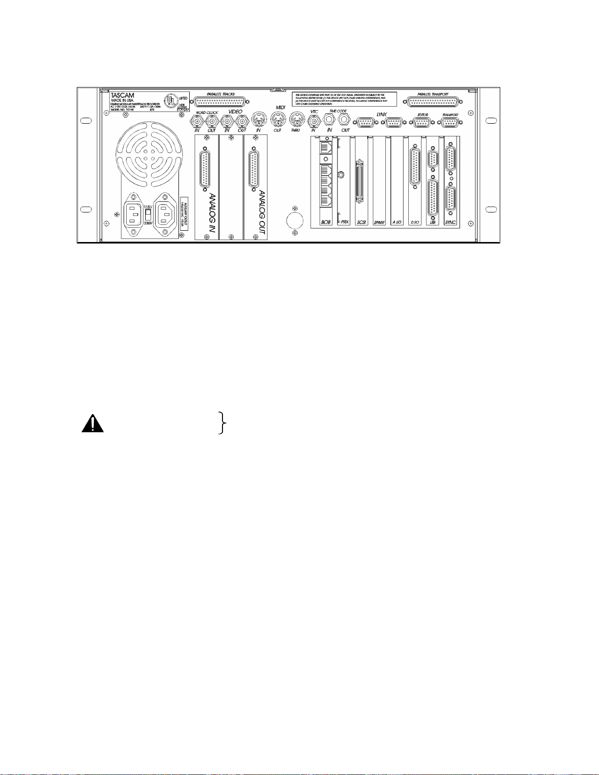
Figure 2-3. MMR-8 Back Panel
MMR-8 Back Panel Connections
The MMR back panel has connectors for the system analog and digital audio input/output, as well as
various types of synchronization and control signals. The following MMR back panel connections are
described in this chapter, and the pin outs for many of these connectors are given in Appendix D: Cable
Information.
• Analog audio in
• Analog audio out
• Digital audio I/O
• Biphase in (BOB)
• Biphase out (BOB)
• Mono mix audio out (PRX)
• SCSI
• Remote control (UI/B)
• MMR bus (Sync)
• Word clock in
• Word clock out
• Video in
• Video out
• Midi in
• Midi out
• Midi thru
• VITC in
• Time code in
• Time code out
• Lynx (2 connections)
• Editor (Sony 9-pin)
• Transport (Sony 9-pin)
• Parallel Tracks
• Parallel Transport
Not intended for public telecommunication network connection
MMR-8 Tascam MMR-8 Owner’s Manual • Chapter 2 • Installation

Audio Connections
All audio inputs and outputs (both analog and digital) connect to/from the MMR-8 using DB-25
connectors. The pin configuration used on the DB-25 analog audio connectors is identical to that used for
Tascam DTRS format digital tape machines such as the DA-88. Two female DB-25 connectors are used
for the analog connections, one for input and one for output, as labeled on the MMR back panel. A single
female DB-25 carries all eight channels of AES/EBU digital input and output signals.
Analog In/Out Connections
All analog inputs and outputs use balanced signals designed to mate with standard 600-ohm devices using
+4 dBu levels. Internal trim pots are available to set the exact input levels, as required to match external
equipment, although the MMR-8 is factory set to a nominal +4 dBu in and out. The inputs can also be set
for a nominal -10 dBu level for unbalanced consumer and semi-pro equipment signal levels.
Analog audio processing is done on two separate 20-bit Analog to Digital and Digital to Analog converter
cards mounted within the MMR-8. These converters are mounted in a special shielded cage within the
MMR and are attached via ribbon cable to a card (labeled A I/O) plugged into one of the system ISA bus
slots on the PC motherboard. These A/D and D/A boards have their own power supply separate from the
main PC power supply. Maximum load is 12.28 vrms.
Digital In/Out Connections
A single female DB-25 connector is used to provide four stereo digital inputs and four stereo digital
outputs. Tascam DA-88 analog I/O cables can be adapted for use as Digital I/O cables by using 4 XLR
gender adapters. Digital input 1 is the default reference track for the AES/EBU reference. This can be
changed to use digital input 3, 5, or 7 from one of the other three digital input pairs using Setup Menu 600
(Dig In Ref Track).
NOTE: The digital clock signals coming from any external device connected to the AES/EBU inputs will
force the MMR-8’s internal clock to try to lock to it when digital input is selected (Setup Menu 500). This
can cause playback and record problems if the clock source is not accurate. If this occurs set that track to
use the sample rate converter in Setup Menu 500 (Input Source).
Monitoring Connections
For monitoring at the MMR-8 there is a mono headphone jack on the front panel (compatible with stereo
headphones of either low or high impedance). For studio Cue or remote monitoring there is a rear panel
line level mono mini phone jack. It is an unbalanced output designed to be connected to external
amplification.
The front panel headphone monitor jack is controlled by the LEVEL control located next to the jack on
the front panel. Press the MON key and select the desired tracks using the Track Select keys to choose
which of the MMR-8 tracks will be summed to appear at the headphone jack output. The rear panel jack
is a pre-LEVEL control, so it is a fixed line level output (-10 dBu), and it always presents a summed
output of the audio channels selected using the MON function on the front panel.
22 Tascam MMR-8 User’s Guide • Chapter 2 • Installation MMR-8

23
Timecode and Video Reference Signals
To accurately synchronize the MMR-8 to film or video, or with other audio playback equipment, some
method of providing a stable timing reference must be used. Because the MMR-8 is very flexible, there
are numerous methods one could use to connect film and video equipment. The best method depends
upon the chosen method of sync, the other equipment that is being controlled, and whether the MMR-8
will be the master or a slave to the other equipment. This section covers the various reference signals
available on the MMR-8 system and their applications.
Video In/Out
Most video post houses have a common house sync signal to lock all the audio and video equipment in
the facility to a standard video reference signal. This insures that all devices receiving the house sync
signal will lock together to the edge of the video frame. The house sync signal can be black burst,
composite sync, or color bars in NTSC or PAL format. The house sync video reference signal should be
connected to the VIDEO IN connector on the back of the MMR-8. To loop the connection through the
MMR, connect the MMR VIDEO OUT to the next device that will use the house sync signal. If there is
not a loop through connection then the VIDEO OUT may need to be terminated, depending upon the
facility signal design. To set the MMR frame reference to use this video input, choose setup menu 001,
Frame Reference, and set the value of this parameter to be Video Reference.
SMPTE/EBU Time Code In/Out
The MMR has two stereo phone jack connections using ¼” Tip/Ring/Sleeve connectors (with the tip
being + and the ring being - on a balanced signal) for synchronizing the operation of the MMR to other
devices using SMPTE/EBU Longitudinal Time Code (LTC). To synchronize the MMR to an external
device which outputs SMPTE/EBU LTC, connect the time code audio output of the master device to the
MMR TIME CODE IN jack. The MMR-8 can also generate a stable SMPTE/EBU time code output
(equivalent to a time code track signal) that can be used to synchronize external equipment or to stripe
time code onto tape. The TIME CODE OUT jack will always output SMPTE/EBU LTC when the MMR
is playing.
VITC In
Many videotape formats can record time code within the vertical interval space between each frame of
video. This type of time code recording is known as Vertical Interval Time Code, or VITC. The
advantage of this method is that a valid time code signal can still be generated even when the tape is
paused to show a single frame of picture, since the helical scan heads of the tape machine are continually
scanning the picture (and thus the VITC signal). The MMR-8 has a 75-ohm connection, using a BNC
connector to receive VITC. To use VITC time code with the MMR, connect the video machine’s VITC
output to the VITC IN connector on the MMR-8.
MMR-8 Tascam MMR-8 Owner’s Manual • Chapter 2 • Installation

Biphase Connections
Biphase is a control signal typically generated by a film projector and is traditionally used to interlock the
operation of the film with sprocketed magnetic tape machines. The Biphase Operations Board (BOB) on
the back panel of the MMR has four biphase input connections and one biphase output connection for
synchronizing the operation of the MMR-8 to film transports. Use Setup Menu 100, Sync Group, to select
which of the four Biphase inputs (Sync Groups) will control the system. The biphase connections use
6-pin modular RJ-12 connectors (like those used on commercial phone systems) and twisted multi-pair
cabling (Category 5 Ethernet). Up to 100 feet of cable can be typically run from a biphase device to the
MMR-8 or vice versa. The pinout diagram for these connectors is given in Appendix D: Cable
Information.
Unlike time code, Biphase gives only speed and direction and does not contain an absolute
address. To set the MMR to lock to biphase, or to be a biphase master device, use Setup Menu
000, Control Mode. The various biphase parameters such as frame rate, pulse rate, acceleration, etc. are
set in the 300 series Setup Menus. Not intended for public telecommunication network connection.
Digital Audio Sample Reference Connections
In combination with a frame reference for video and film, there may also be a sample reference for the
audio. The sample reference can be taken from one of the digital inputs, the frame reference, the Word
Clock input (if there is an active signal on that input), or the system’s internal clock source. These
connections are described here in more detail.
Word Clock
Word Clock is a digital reference signal used by many digital editors and digital tape machines. This
permits two digital audio devices to synchronize their sample clocks to facilitate digital audio transfers
between machines, and to insure that they are running at precisely the same sample frequency. The signal
is transmitted on an unbalanced coaxial cable that terminates into a BNC connector at the MMR-8 end.
The MMR-8 has both a digital WORD CLOCK IN and a digital WORD CLOCK OUT connection using
BNC connectors.
When an external tape machine is to control the sample rate of the MMR-8, connect the Word Clock
output from that machine to the WORD CLOCK IN on the MMR-8. When the MMR-8 is to control the
sample rate of an external machine connect the WORD CLOCK OUT from the MMR-8 to the Word
Clock In on the controlled machine. The maximum practical cable distance is up to 100 feet. Use setup
menu 002 to select the sample reference for the MMR-8 system. Normally this is a 48 kHz TTLcompatible (5 volt) signal.
AES/EBU Sample Rate
When using AES digital audio input, the audio sample reference for the MMR-8 can be taken from one of
the four AES digital inputs. Use setup menu 002 to select the sample reference for the MMR-8 system.
Setup Menu 600 selects which AES/EBU digital input pair will be used for the reference signal (input
1+2, 3+4, 5+6, or 7+8).
24 Tascam MMR-8 User’s Guide • Chapter 2 • Installation MMR-8
 Loading...