


688
<
!
>.
,
.'!
I'
i
j.
io
t·
1:
c'"
"
..
f'
.
l'~·,
'
,
,!
. /
r-
~
.
, J
I,
.
TASCAM
TEAC
Professional
Division
·MIOISTUOIO
.'
",,",
'- .
,
i I
.
~
}
I •
,1
/
./
j
.(j;
I,
.
.
'~i700'~Ol
/
.J
~
Table
of
Contents
"';'.
Block
Diagram
5
MIDI
MIXER
CONTROL
Transmitting MIDI Program Change
commands
INTRODUCTION
from
the
688 .,
,34
Understanding
the
Mixer
Scene Display
7 Changing scenes via External MIDI commands
35
Multitrack
Cassette Recorder
9
Controlling
Mutes
with
MIDI Note messages
35
The Recording System
11
Mixer
Subsystems
11
FEATURES
AND
CONTROLS
Mixer
section
36
BRIEF
GUIDE
14
Monitor
Section
38
Scene Routing Display and Controls
39
OPERATIONS
GUIDE
Recorder Section
43
Tracking
17
Autolocator
Section
45
Overdubbing
19
Meter
Section
46
Mixdown
20
Back panel
47
Punch-in
or
Insert Recording
21
Front Panel
49
Bouncing tracks (ping-pong)
24
Using
the
Scene Display
25
Transferring
All
Scenes
27
Care
and
Maintenance
50
Using
Effects
with
the
MIDISTUDIO 688 28
How
the
dbx
works
51
Specificati
0
ns
52
MIDI
SYNCHRONIZATION
level
Diagrams
55
Introduction
to
MIDI Sync
30
Optional
Accessories
57
The Recording system
with
MIDI
implementation
chart
58
MIDI
Synchronization
31
Procedures
for
MIDI Sync Recording
32
FACTORY
PRESET
SCENES
59
Mixer
operation
during
MIDI Sync
33
Us'jng External Sync Devices
33
Synchronizing the 688 to another tape deck 34
C 1990 TEAC
Corporation.
All
rights
reserved
under
international
and
Pan
American
copyright
conventions. This book
may
not
be reproduced in
whole
or
n part.
by
mimeograph
or
any
other
means,
without
permission.
Important
Safety Precautions
A
CAUTION:
TO
REDUCE
THE
RJSK
OF
ELECTRIC
SHOCK,
DO
NOT
REMOVE
COVER
(OR
BACK).
NO
USER-SERVICEABLE
PARTS
INSIDE.
REFER
SERVICING
TO
QUAUAED
SERVICE
PERSONNEL.
The
lightning
flash
with
arrowhead
symbol,
within
an
equilateral
triangle,
is
intended
to
alert
the
user
to
the
presence
of
uninsulated
-dangerous
voltage-
wRhin
the
product's
enclosure
that
may
be
of
sufficient
magnitude
to
constnute
a
risk
of
electric
shock
to
persons.
The
exclamation
point
wnhin
an
equilateral
triangle
is
intended
to
alert
the
user
to
the
presence
of
important
operating
and
maintenance
(servicing)
instructions
in
the
literature
accompanying
the
appliance.
. "
"'.
\
I
'",
"
\..
This
appliance
has
a
serial
number
located
on
the
rear
panel.
Please
record
the
model
number
and
serial
number
and
retain
them
for
your
records.
~odel
number
_
~rial
number
,
WARNING:
TO
PREVENT
FIRE
OR
SHOCK
HAZARD,
DO
NOT
EXPOSE
THIS
APPLIANCE
TO
RAIN
OR
MOISTURE~
-2-
----
-

N<l._
D1SCHAIi!(;[ u,,"r
lfll[C
5£CT00I
1'10-20)
--~:.
WlW(
.
-----:
~~,~~C:OO~
(N(C
Nf.f
%SO.
PART
H)
NEe
-
HA.TlONAL.
£L.£CfltlCAl. COD(
EXAMPLE
OF
ANTENNA
GROUNDING
AS
PER
NATIONAL
~ICAI,(',()DE
13. Cleaning -
The
appliance should be cleaned only as recom-
mended by
the
manUfacturer.
14. Power Lines - An
outdoor
antenna should
be
located
:!JWay
from power lines.
15.
Outdoor
Antenna Grounding -
If
an outside antenna
is
connected to
the
receiver,
be
sure the antenna system
is
grounded so
as
to
provide some
protection
against voltage
surges and built
up
static charges. Section 810
of,
the
National Electrical Code, ANSI/NFPA No.
70
- 1984, pro-
vides information with respect
to
proper grounding of.
the
mast and supporting structure, grounding
of
the
lead-iii
wire
to
an antenna discharge unit, size
of
grounding con-
ductors, location
of
antenna-discharge unit, connection
to
grounding electrodes, and requirements for
the
grounding
electrode. See Figure below.
£L£Cn:UC
S(fMC(
[CUlPI.((NT
16. Nonuse Periods -
The
power cord
of
the appliance should
be 'unplugged from the
outlet
when left unused for a long
period
of
time.
17. Object and Liquid Entry - Care should,
be
taken so
that
objects
do
not
fall and liquids are
not
spilled
into
the en-
closure through
openings.'
.
18. Damage Requiring SelYice - The appliance should be ser-
viced
by
Qualified service personnel when:
A.
The
power.:supply
cord
or
the
plug has been damaged;
or
B.
Objects have fallen,
or
liquid has been spilled into
the
appliance;
or
C.
The
appliance has been exposed to rain; or
D.
The
appliance does
not
appear
to
operate normally
or
exhibits a marked change
in
performance;
or
E.
The
appliance has been dropped,
or'the
enclosure
dam'
aged.
19. Senlicing -
The
user should
not
attempt
to
service'
the
appliance beyond
thet
described
in
the operating Instruc-
tions.
All
other
servicing should be referred to qualified
service personnel.
CAUTION:
• Read
all
of
these instructions.
• Save these instructions for later use.
• Follow all warnings and instructions marked on
the
audio equipment.
1. Read Instructions - All the safetyand operating instructions
should be read before the appliance
is
operated.
2. Retain Instructions -
The
safety and operating instructions
should
be
retained for future.reference.
3. Heed Warnings -
All
warnings
on
the appliance and
in
the
operating instructions should be adhered to.
4. Follow Instructions - All operating and use instructiom
should be followed.
5.
Water and Moisture - The appliance should
not
be used
near water - for example, near a
bathtub,
washbowl, kitchen
sink, laundry
tUb,
in
a
wet
basement,
or
near a swimming
pool, ete.
6.
Carts and Stands -
The
appliance should be used only with
a
cart
or
stand
that
is
recommended
by
the manufacturer.
6A. An appliance and
cart
combination should be moved with
care. Quick stops, excessive force, and uneven surfaces may
cause
the
appliance and cart combination
to
overturn.
7.
Wall
or
Ceiling Mounting -
The
appliance should be mount-
ed
to
a wall
or
ceiling only as recommended by
the
manu-
facturer.
8.
Ventilation - The appliance should be situated so
that
its
location
or
position
does
not
interfere with its
proper
venti-
lation.
For
example,
the
appliance should
not
be situated
on
a bed, sofa, rug,
or
similar surface
that
may block the
ventilation openings; or, placed
in a built·in installation,
such
as
a bookcase
or
cabinet
that
may impede the flow
of
air through the ventilation openings.
9. Heel -
The
appliance should be situated away from heat
sources such as radiators,
heat
registers, stoves,
or
other
appliances (including amplifiers)
that
produce heat.
10. Power Sources -
The
appliance should be connected
to
a
power supply only of the
type
described
in
the operating in-
structions
or
as marked
on
the
appliance.
11. Grounding
or
Polarization -
The
precautions
that
should
be taken so
that
the grounding
or
polarization means
of
an
appliance
is
not
defeated.
12. Power-Cord Protection - Power-supply cords should be
routed so
that
they are
not
likely
to
be
walked on
or.
pinch-
ed by items placed
upon
or
against
them,
payi!lg particular
attention
to
cords
at
plugs, convenience receptacles, and
the
point
where
they
exit from the appliance.
Safety
Instructions
-3-

Introduction
In
additIon. the MIDISTUDIO
~n
be
synchronized
to
other
mult/tracks
(like the
TASCAM
MSR-16
or
238)
or
to
II
video
cassette
recorder
using
the
TASCAM
MIDiiZER.
(Connection
of
tho
MIDilZER to a
VCR
mav
require
the
IF-
1000 Parallel Interlace U
nit.l
The 688
MIDISTUDIO®
is an
8-channel
multitrack
Cas-
sette
recorder,
1I
20
input
mixing
system
with
electronic
routing
control,
and s MIDI Tape
Synchronizer
combined
into
a
single
workstation.
It's
the
first
a-track PORTA-
STUDIO~
expressly
designed
to
meet
the
challenge
of
the MIDI
revolution.
Its
mixing
lection
Is
designed
In
a
new
way
to
accommodate
the greater
number
of
line In-
puts
in
a
typical
MIDI
studio,
up
to
20
et
once
plus
4 ef-
fect returns. Each
main
channel can acceas
up
to 4 effects
busses,
so
you
can use a
variety
of
different
effects
(reverbs, delays, choruses etc.) on
different
Inputs. MIDI
Tape Synchronization
with
Song Position Pointer (same as
that
used
by
the
TASCAM MTS-301 is
built
In.
so
that
the
capabilities
of
MIDI sequencing can
be
blended
with
the
advantages
of
multitrack
recording.
Note
for
U.K.
Customers
only
Due
to
the
variety
of
plugs
used
In
the
U,K.,
this
unIt
Is
sold
without
an
AC
plug.
Please
request
your
dealer
to
install
the
correct
plug
to
match the
maIns
power
outlet
where
your
unit
will
be
used
as
per these instructions.
..,-4-
NOTE:
This
voltage
conversion
is'
not
possible
on
models
sold
in
the
U.S.A., Canada, U.K.,
Australia
or
Europe.
You'll
get
the
best
results
by
having
your
system
set
up
so
you
can
experiment
with
it
'as
you
read.
Don't
make
the
mistake
of
booking
a crucial
recording
session before
you've
had free
time
to
really
get
to
know
your
688.
This manual is
divided
into
sections.
INTRODUCTION:
Everyone,
from
expert
to
novice,
should read
this
part.
OPERATIONS
GUIDE:
This
covers
the
"how
to"
proce-
dures
of
basic
multitrack
recording
with
the 688.
It
ad-
vances
to
instructions
about
us.lng
effects,
bouncing
tracks, and
punching
In.
MIDI OPERATIONS:
After
you've
worked
with
and are
comfortable
with
the
mixer
and
the
recorder
sections,
read
this
If
you
want
"how
to"
procedures
of
MIDI
syn-
chronization.
Non-MIDI
users
don't
need
this
part.
FEATURES
AND
CONTROLS: Everyone
should
use
this
·what
is
it?"
dictionary
that
defines
every
control
and
indIcator
on
the
688
In detail.
The
688 MIDISTUDIO
is
different
in
major
ways
from
previous
PORT
ASTUDIOs.
The
basic
structure
of
the
mixer,
the
features
of
the
tape
transport,
the
MIDI
im-
plemuntation,
llnd
the
electronic
switching
are
811
new.
To get the
most
out
of
your
688, spend
some
time
now
to
READ THE
MANUAL!
You'lI
be
ghid
you
dId.
Even
If
you're
experienced,
you'll
discover
Borne
tricks
you
haven't
tried before.
How
to
Use This
Manual
Precautions
Changing
the
Memory
Back-up
Battery
The
included
battery
lasts
about
5 years.
We
recommend
'you
to
change
the
battery
In
advance
to
prevant
-accidental
erasure
of
the
contents
of
the
99 scene
mem-
ories.
If
the
battery
has
run
low,
when
you
turn
on
the
688
you
will
see
the
switch
settings
of
factory
preset
scene 01, insteed
of
the
last scene
you
used.
For
infor-
mation
on
how
to
change
the
battery,
consult
TASCAM
or
your
nearest
TASCAM
dealer.
Voltage
Conversion
_-
This
unit
i~
adjusted
to
operate
on
the
electric
voltage
epeclfied on
the
unit,
power
cord
tag,
or
plICklng carton.
\
\
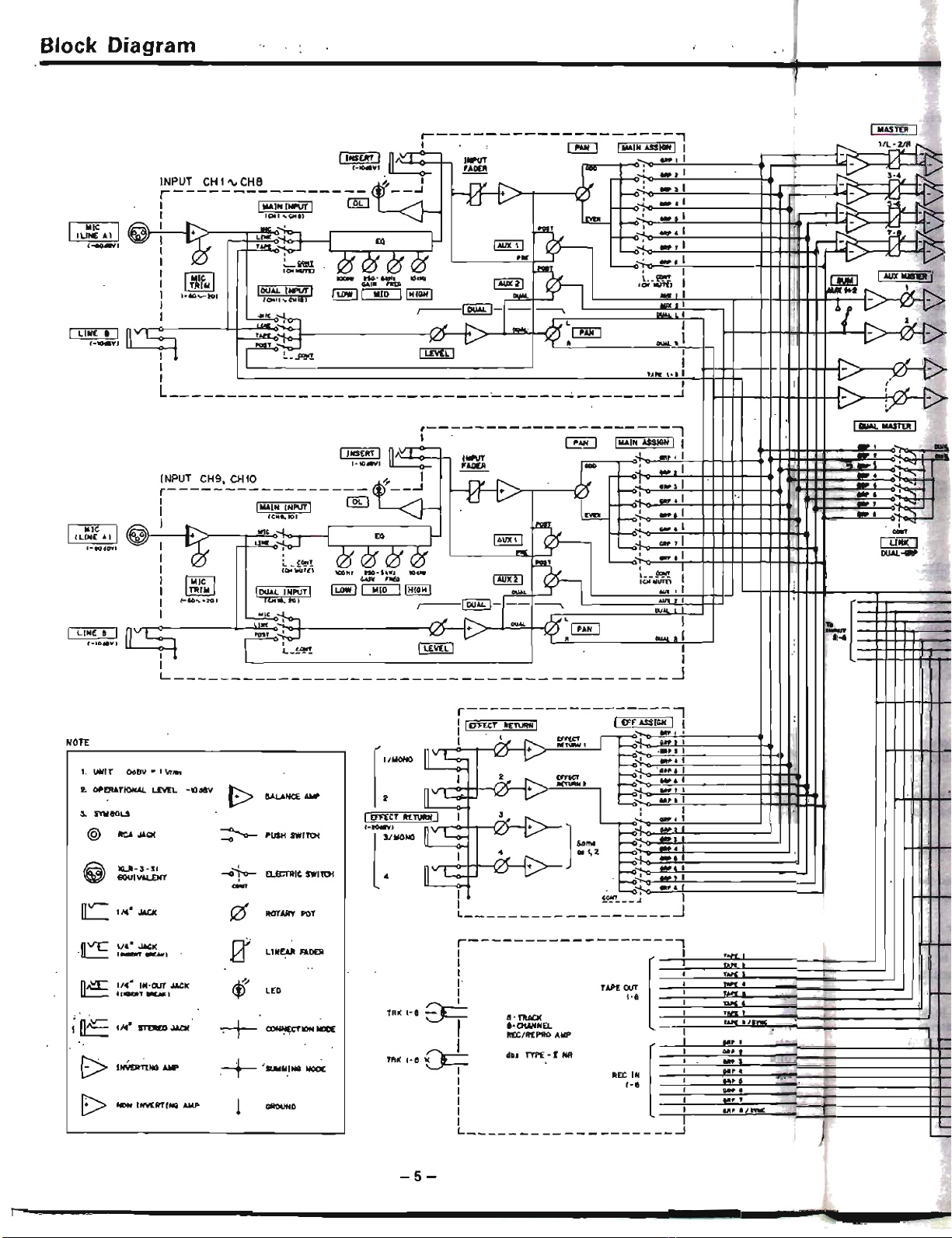
Block
Diagram
rIiiCI
hill
~&Q2
(-to.""
LINE a I
1-IOillt'J
.-----
---------
----
---~
IIlUAL
IlASn:R I
1_
.
~
IIlAINASSIGNII
Il
ll
_.
JINSERT I
n~
INI'IIT
=-~,
:;
~.
I
'Will-u+:m++:t::::~·
if
I-tO
..
...,'
~
~_
ClOO
_
....
: I
---..
...
\ •
~~~-~:"-5~1~
------14~--J
rY..
Ix-'
1
-:
I.
I
IMAIN
INPUT)
[K]
-U )(,J
~~
_...
::
'
:
«."!Ol
~~
_.1
I
,~
~
MIt
I-
.1
1 . I
000
I"
u"'~"}o-
EO
IAlJ)(
'l,
~.l
1 r I
L7:
I
I : COlo'
r2f r2f
_
r2f
<21
_,
I I I
DUAl.
__
I
~-"li,'i';
'OOHI
no-hKt
10...
h'
COOIT
I
I IoiiCl .... "'..
IAIIX21
le.-OUT',
I
I
~
10000INPUTI ILOWI
~
IHIGHI
....
,
....
If
I
(-10
...
-201
(("ft.
to)
~I
DUAL
I-t--
~
'wI
I
I
M't
-.J
"'"
o.
--1-""
rl
,",AI.
h/
L
r.o.;-,
I
II
S
""-0:""
l(..I"
V.~
.......
1
I 1 -
L_~'!!'!.
_ I
LEVELl
- I
I I
L
~
-
-
~
-
r------------------,
!
[~l
~~:~
..
i
~~~
I:
TAPEDIIT'
.-.
l
t-8
:
:~:
TftK
t-a
~I
8-TlIAa<
I"
~,
.-otAHNEL
'
....
"'
REC/REPRO
AMP
.:
TRK
'-8
~
d~.
TYPE-I
NR
REt
IN
[~~l~~~~~:~;
~~~'~;~~~~~~~~~~~
;
1-8
:
:::
: J
~
I
I • ,
~
t
11m-:
!
I I
L
~
r------------------.
I IEff'!:CT IlEruRN I I
EFF
USt'N
I I
J
.,
M?l
I
t
At
~
I r
~<l'1-,
_~
..
!!:.~.
',
-+.
f
"MONO
IIV
~
IU
•
':::
~
~_o"'}_o_~.~
••
C!.~l!-----_+-+-W_l
lAc..
=,
t:~':=~
...
~·~'t:====~tatHl
2
It
~
IU
I [ ,
::::
IEffECT Il£ruRH I 1
At
:
_.1
,._[
]/MD~
L::::::
IU
+ ]
Somo
,-::
:
I
rl
•.
~
2
t:~:;:~:~_~~.~l:::::::::::::::~-J
4 n
v-e:::
10"
..
.
t~:--:..i~~~~'
O~.-j..::i~;~:f:::::::::::::::~-=J
~
_.
I
~
J I
L
~
2. Of'fRATIOI<AI. L£'JEL
-tOdav
t.
UklT
Odev'"
I
vr
....
@
fICA
JAC(
~
PUSH
SW1TCti
(@)
leLA
-3-31
-0'1-0-
£l.EI:11lIC
$W1Tt:H
EO
UIVot.L£NT
..:...
nv-
114
•
JACK
((1
ROTARY
POT
n
ve
1/4
• JACK
IT
LINEAl!
FADER
'''-''
-..,
n~
114
·
IN-OUT
.lACK
<tr
.,-
T
.....
'
LED
..
~
,14"
~
1
"'--
STDI£l)
.u.ac
~IDNIIU
G>
INVEJrTl
NO
.....
~
'SUIIMUIQ
~
E>
-
INV£RTIHG
AMP
1
GAOOHD
NOTE
II
t
-5-

-
=
--'
L
I
I
!
111:1"
4
ca,".
Ollt.
I
1 ,
..
7
~..
...
••
I'S'I'WC
---
i"O"
I
,
i~
,
;"0-
,
.
I
-6-
LlD ltETEJl
Understanding
the
Mixer
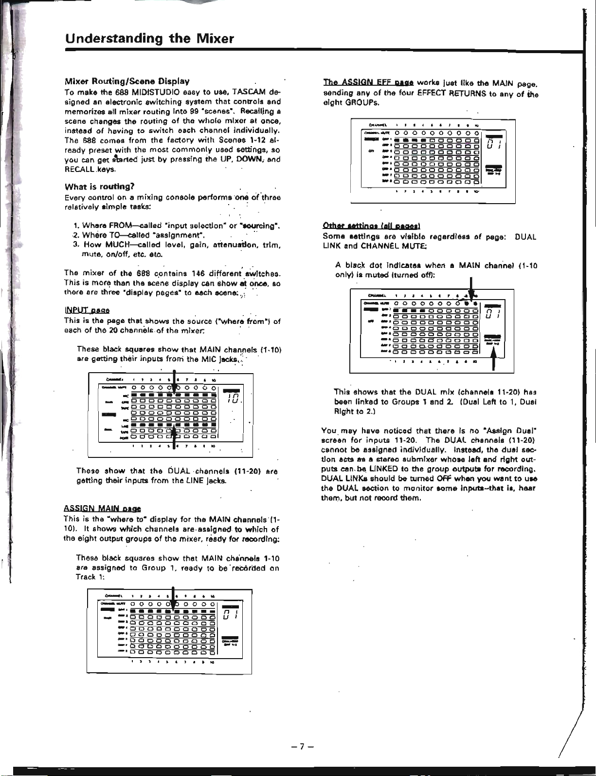
These
show
that
the
DUAL
,channels
(11-20) are
getting
their
inputs
from
the LINE
Jacks.
.....
,
.....
00
0
o 0
00
0
00
-
.......
'
••••
000000
n I
.-10
0 0 0 0 0 0 0 0 0
U
I
...
11lllUODODOClClODD
c.
4
DDODDDOODO
~.
0 0
DOD
CJ 0 0 0 0
-
.,.
0 0 0 0 0 0 0 0 0 0
--
""00,0
0.0
CJ
0 0
Cl
0
-
..
...
·OCJODOODOOp
I
-,
1
I
•
.
• •
"
•
.....
--
00
000000
••
-
_
...
·•
••••
000000
n
,
"'10
Cl
0 0 0 0 0
DOD
U
I
-
-.
Cl
0 0 0
CI
0
CI
0 0
Cl
"·ODDDDODDOD
_.
0 0
CI
0
Cl
Cl
0 0 0
Cl
-
_.
0 0 0 0 0 0 0 0 0
Cl
-=I
""DODD.DoooeD
-"OOOOOClOOOO
, I
I ..
.
•
,
•
•
to
1
The
ASSIGN
EEf
pag.
works
just
like
the
MAIN
page.
sending
any
of
the
four
EFFECT RETURNS
to
any
of
the
aight
GROUPs.
A black
dot
indicates
when
a
MAIN
chan'nel
(1·10
only) is
muted
lturned
off)'
This
shows
that
the
DUAL
mIx
(channels 11-20) has
been
linked
to
Groups 1 and 2. (Dual Left
to
1, Dual
Right
to
2.]
, ,
:I
lit
5 , 1 • •
1lD'
CH
.......
II.
'!J<IIi.'ltM)
Other
ttttjngs
(III
plgosl
Some
lettings
are
visible
regardless
of
page: DUAL
LINK and CHANNEL MUTE:
You
may
have
noticed
that
there
is
no
·Assign
Dual"
screen
for
inputs
11-20. The
DUAL
channels 111-20)
cannot
be
assigned
individually.
Instead,
the
dual
sec-
tion
acts
as
a stereo
8ubmixer
whOse
left
and
right
out-
puts
can be LINKED
to
the
group
outputs
for
recording.
DUAL LINKs should
be
turned
OFF
when
you
went
to
use
the
DUAL
section
to
monitor
some
InputJl-that
is,
hear
them,
but
not
record them.
._,
In
tU,
00000
0000
•••••••••••
...
OCJODOODDOO
_DOOOClDClOClCl
ClODOClOOOOO
..,OOClOOClOClClCl
L.IIII
••••••••••
...
0000 0000
flQRODOD
0000
~
..
l'l_t.T"tO
-
These black squares
show
that
MAIN
channels (1-10)
are
getting
their
inputs
froni
the
MIC jacks.;: . .
Mixer
Routing/Scene
Display
To
make
the
688 MIDISTUDIO easy
to
use, TASCAM de-
signed
an
electronic
switching
system
that
controls
and
memorizes all
mixer
routing
into
99
·scenes·. Recalling a
scene changes
the
routing
of
the
whole
mixer
at
once,
instead
of
having
to
switch
each channel
individually.
The
688
comes
from
the
factory
with
Scenes 1-12 al-
ready preset
with
the
most
commonly
used settings, so
you
can
get
s\lrted
just
by
pressing
the
UP, DOWN, and
RECALL keys.
What
is
routing?
Every
control
on a
mixing
console
performs
'one
ci(three
relatively
simple
tasks: . .
1. Where
FROM-called
·input
selection·
or
·sourclng·,
2.
Where
TQ---allled
·assignment".
"
3.
How
MUCH--called
level,
gain,
attenuation,
trim,
mute,
on/off, etc, etc.
The
mixer
of
the
688
contains
146
different
sWitches.
This is
more
than
the
BC~ne
display
can
show
at
once,
so
there are
th~ee
"display pages"
to
each scene:,.; "
INPUT ,page
This
is
the
page
that
shows
the
source
("where
from")
of
each
of
the 20
channels.of
the
mixer.
' .
ASSIGN
MAIN
page
This
is
the
·where
to·
display
for
the
MAIN
channels'(l-
10). It
shows
which
channels
are,assigned. to
which
of
the
eight
output
groups
of
the
mixer.
readv
for
recording;
These black squares
show
that
MAIN
cha'nnels
1-'0
are assigned
to
Group
" ready
to
be
'recorded
on
Track
1:
.
~,
.
• •
.
•
1.
,
•
•
to
-
....
0
00
0
0"
0
0
00
-
_
...
,
..........
n
,
-
...
~ODOOCJOOOOO
U
I
a.aODOOOClOOOO
"'0000000000
lOW>Il000
00D
OOO
D
~
a.'OOODOODOOD
..
, 0 0 0 a D
Cl
CJ 0 0 0
-~
.
c.r>lo
0
DODO
CJ 0 0 0
.
.
•
.
•
.
,
.
•
..
-7-
--
--
-

Scene
Assign
I
Assign
Input
Input
•
Dual
MAIN
EfF
MAIN
DUAL
Unk
01
GROUP 1
MIC
LINE
GRP 1-2
02
GRP
2
·
·
•
03
GRP
3
· ·
GRP 3-4
04
GRP
4
· · ·
06
GRP6
·
·
GRP
6-6
oe
GRP
6
·
· ·
07
GRP
7
·
·
GRP
7-8
08
GRP
8
·
·
·
IScene
I
Assign
I
Assign
Input
Input
Dual
MAIN
EFF
MAIN
DUAL
Unit
I 12
I GROUP 1-2
TAPE LINE
GRP
1-2
Factory
Presets
The
first
12
scenes
come
from
the
factory
with.
settings
that
will
help
you
get
started. You can see
this
data
in
more
detail
in
the
charts
on
pages 66-60.
Scene 12 is
the
MIXDOWN scene. Here,
the
TAPE
be-
comes the source
of
the
main
channels, and everything
is
assigned in stereo
to
Groups 1 and 2:
These scenes are identical
except
for
their
ASSIGNments.
All
Inputs
are
8ct~ve-the
mics
through
the
MAIN
channels 1-10, and
the
lines
though
DUAL
channels 11-
20,
with
LINKS ON.
Scenes 1-8 are dedicated
to
tracking
or
overdubbing
onto
the
eight
tracks
of
the recorder,
one
at
a time:
Note
that
while
the
XLR jacks
are
labeled MIC on
the
scene
display,
they
can
accept
line-level
inputs
(from
synthesizers, etc.)
if
the
TRIM Is
turned
down.
This makes
it
possible
to
have 20
line
sources
at
once
with
the
688.
A
simple
XLR-to-phone
adapter
is all
that
Is
needed-this
is
why
the jacks are labeled MIC (LINE
A).
These factory presets are
just
a suggestion, and there are
87 blank scenes available so
you'can
build
scenes
that
fit
your
own
studio.
(Even
the
first
12 can
be
erased
or
changed
at
any
time.)
For example,
if
you
want
a synthesizer
plugged
Into
a
1/4"
LINE
(B)
Jack
to
go
through
a
MAIN
channel instead
of
the DUAL,
you
just
have
to
make a scene
with
LINE as
the main channel source. LINE can
be
selected as the
input
for
the
MAIN
channel,
the
DUAL channel,
or
both
channels simultaneously.
The
same is true
for
MIC, and
the eight TAPE tracks.
Tractcing
Mixdown
The
Three
Steps
to
Multitrack
Why
~He
all
these
scenes
and
INPUT
and ASSIGN
switches necessary] Because there are three basic steps
to
multitrack
recording.
In each step, the signal
flow
through
the
mixer
has to change direction:
{[;J
Overdubbing!
:Ia
'V
;;i\~MonilorSection~
M.in
Saction
3
E=§
-'~
----~
4ue::J~
~o,~,,~
L-688
----.J
2
Track
Notice
how
the
arrows
in
the
pictures above change
di-
rection.
In TRACKING and OVERDUBBING,
the
mixer
Inputs
are
usually
microphones
or
Instruments,
goIng
to
different
tracks
of
the
recorder. In OVERDUBBING,
part
of
the
mixer
must
be used
to
monitor
previous tracks
while
you
record
new
ones, so
there
is
a
two-way
flow
through
the
console. In MIXDOWN, signal
comes
from
the
m
...
ltltrack
and is sent
to
an
external 2-track recorder.
On
a
mixer
with
mechanical switches,
you
have
to
press
dozens
of
separate
switches
to
go
from
overdub
to
mix-
down
modes. But because
of
the 688's scene dIsplay, all
you
have
to
do
is change scenes (by pressing
UP,
DOWN,
or
the
number
keys,
then
RECALL),
and
everything
changes
for
you. '
-8-
Mu{titrack Cassette Recorder
The 688 records on
readily
available standard (Philips)
Compact Cassette tape.
high
bias Type II. You can record
on
any
or
all
eight
tracks
of
the
688
at,
any
time.
• There are
two
counter
displaya,
one
ahowing
the
current
position
and
the
other
showing
an autolOCllte
or
punch point.
With
proper
operating
techniques,
It
la
not
necessary to
leave
a,
guard
band between
music
and sync
tone
tracks
because
of
the
low
crosstalk
of
the
TASCAM
head,.
Us-
ing
OBX noiae
reduction
the
'sonic
quality
of
the
688
is
only
exceeded
by
reel-to-reel
recorderl
with
noise
re-
duction.
The
transport
controls
of
the MIDISTUOIO are
micropro-
cessor operated.
allowing
high
reliability
and
automatic
functions
that
make
the
unit
easier
to
use: '
• REHEARSE and AUTO IN-OUT use
the
counter
to
electronically
mark
punch-in and
out
tim'es. Once you
have
set
the
points,
you
can practice
an
insert several
times
before
actually
recording,
with
machine
precision each
time.
• A three position autolocator (MEMO 1 and 2 and Zero)
allows
key
positions
to
be located automaticallv.
• REPEAT
allows
a 8ection
to
be
played'
ovar
and
over
between
the
MEMO
1 and
MEMO
2
points,
for
re-
hearsal.
• The
counter
display
can
show
either
reel revolutions
or
acts liS a
timer
,hawing
how
long
tha transport
hal
been
in
PLAY
or
RECORD
mode.
In
addition,
the
tranaport
capstan
motor
la ae(V()-C()n-
trolled,
so
that
the
tape
speed can
be
Increased
or
de-
crea~
with
the
PITCH CONTROL
to
mateh
pltx:h
or
for
specIal effects.
The
capstan can be externally
controlled
by
a eynchronizer (such
aa
the
TASCAM MIDIIZER) con-
nectad
to
the
ACCESSORY 2 Interface'
~f
the
688
80
tha
tape
will
"lock"
to
anothar
recordar, either audio
or
video.
using SMPTE Time Code. '
The 688 can be
remotely
controlled
by
the
optional
RC-88
remote
control
unit
which
puta
the
transport
controls
up
to
5 m (15
ft.)
away.
Punch-In and Punch-out can be
engaged
using
the
optional
RC-30P
footawitch,
which
gives
you
an
"extre
hand"
In
the
r.cording
proceaa.
During
Rehearse and
Auto
In..()ut modes.
you
can even
put
the
deck
into
PLAY
or
REWINO
with
the Re-30P.
for
totally
"hands free"
operation.'
' ,"-":;
Track Format and Tape
Recommendations
• I
.•.•.
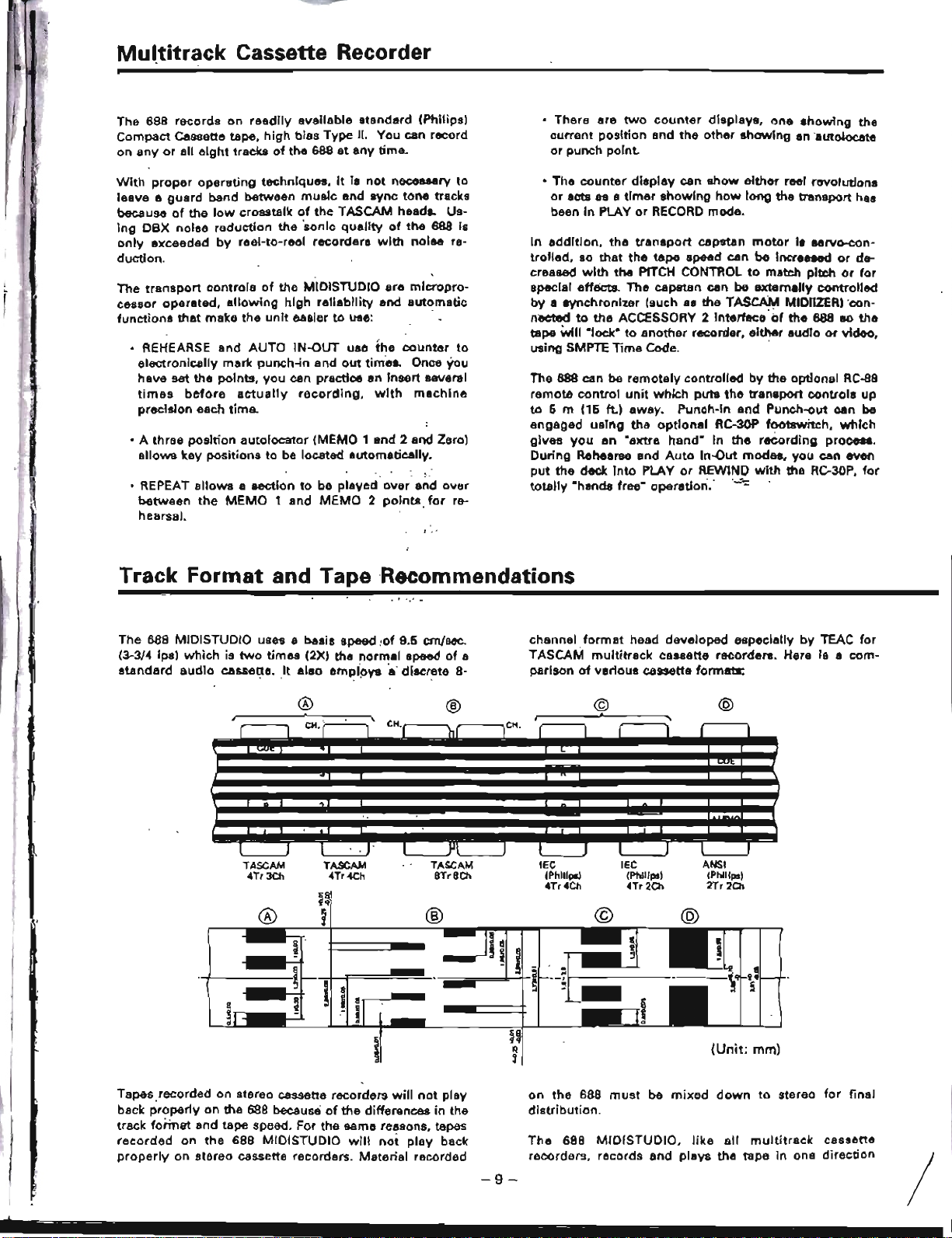
The 688 MIDISTUOIO uses a basis speed
!of
9.5
em/sec.
(3-3/4 ips)
which
is
two
times
(2X) the
normal
speed
of
a
standard
audio
cassette.
It
also
empioV8
a'
discrete
8-
channel
format
head developed especially
by
TEAC
for
TASCAM
multitrack
cassette recorders. Hera Is a
com-
parison
of
venous
cassette formats:
@
(Unit:
mm)
ANSI
(Phlllpsl
2Tr
20>
IEC
(Phllipsl
4Tr2Ch
©
®
®
TASCAM
TASCAM
TASCAM
lEe
4Tr3Ch
4Tr4Ch
8Tr8Ch
(PhiliPS)
4Tr4Ch
~q
®
~
®
1l
I
II
!
o
~
!
~
~
i
~
II
S
!
..
3
d
S
~~
i
tl
,
I
CH. r---"I '
I
.
,
r 1
CH-r
'hf
lCli,
r 1 I
I I I
"
I I I ' J I
Jll
J I J
I I I I
Tapes,recorded on stereo cassette recorders
will
not
play
back
properly
on the 688 because
of
the differences
in
the
track
format
and tape speed. For the same reasons, tapes
recorded
on
the
688 MIDISTUDIO
will
not
play
back
properly
on stereo cassette recorders. Material recorded
-9-
on
the
688
must
be
mixed
down
to
stereo
for
final
distribution.
The
688
MlDISTUDIO.
like
all
multitrack
cassette
recorders, records and plays the tape in one
direction
/
-----
---
----
-
only.
The 688
needs
the'
entire
width
of
the
tape
to
record
its
eight
tracks,
eliminating
the
option
of
recording
on
both
sides
(actually,
it's
both
directions).
Therefore,
you
should
decide
which
side
(side
"A"
or
side
"a")
you
want
to
use
and
use
that
side
exclusively.
It's
a
good
idea to
get
Into
the
habit
of
consistently
using
the
same
side on all
multitrack
tapes.
Tape
Type
The
688
MIOISTUDIO
is
Internally
adjusted
for
,HIGH
BIAS
"Type
II" taPe.
This
means
that
for
best
results,
you
should
'only
use
tapes
of
this
type.
Examples
~ould
in-
clude
TOK SA,
Maxell
XL-II
or
equivalent
formulations.
We
strongly
suggest
that
you
select
one
good
quality
brand
and
use
it
exclusively.
The
time
you
spend
creating
your
multitrack
master
is
much
more
valuable
than
the
money
you
save
by
buying
inferior
tape.
The
cassette
shell
essentially
becomes
e
part
of
the
688's
transport.
Poor
quality
shelis
can
cause
wrinkles,
snarls
and
shredding'
of
the
edges
of
the
tape
with
use. Even
small
scratches
on
the
tilpe
oxide
can
cause
"dropouts"
(temporary
loss
of
signal)
on
one
or
more
of
the
tracks.
HiQ!!
Q1JalitY
tapes are less
likely
to
cause
problems
in
the
long
run,
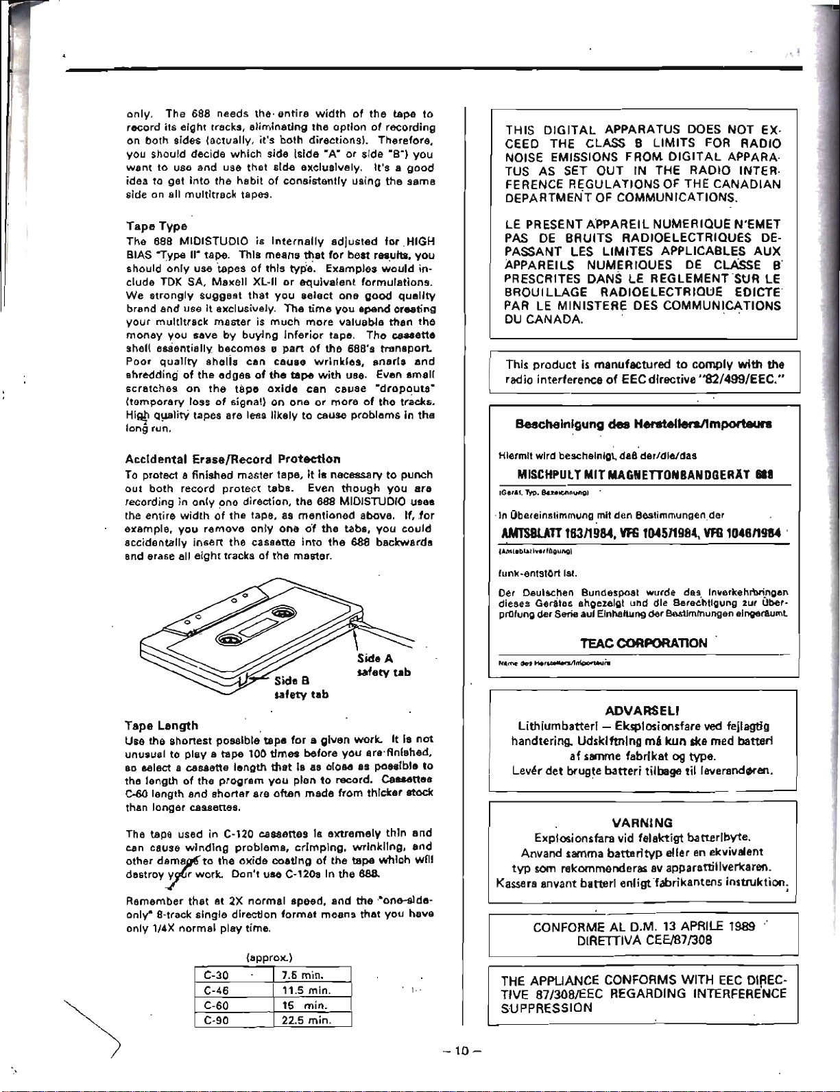
Accidental
Erase/Record
Protection
To protect a
finished
master
tape,
it
is
necessary
to
punch
out
both
record
protect
tabs.
Even
though
you
are
recording
in
only
one
direction,
the
688 MIOISTUDIO uses
the
entire
width
of
the
tape, as
mentioned
above.
If, ,for
example,
you
remove
only
one
o'f
the
tabs,
you
could
accidentally
insert
the
cassette
into
the
688
backwards
and erase all
eight
tracks
of
the
master.
Tape
Length
Use
the
shortest
possible
tape
for
a
given
work.
It
Is
not
unusual
to
play
e
tape
100
times
before
you
are'finlshed,
80
select a cassette
length
that
i8
as
close
as
possible
to
the
length
of
the
program
you
plan
to
record.
cassettes
C·60
length
and
shorter
are
often
made
from
thicker
stock
than
longer
cassettes.
The tape used
in
C-120
cassettes
Is
extremely
thin
and
can cause
winding
problems,
crimping,
wrinkling,
and
other
d8~r
to
the
oxide
coating
of
the
tape
which
wnl
destroy
rr
work.
Don't
use
C-120s In
the
68B.
Remember
that
at
2X
normal
speed,
and,
the
"one-slde·
only"
8-track
single
direction
format
means
that
you
have
only
1/4X
normal
play
time.
(approx.)
THIS DIGITAL APPARATUS DOeS NOT EX·
CeED
THE
CLASS B LIMITS
FOR
RADIO
NOISE EMISSIONS FROM
DIGITAL
APPARA·
TUS
AS
SET
OUT IN
THE
RADIO INTER·
FERENCE REGULATIONS
OF
THE
CANADIAN
DEPARTMENT
OF
COMMUNICATIONS.
LE
PRESENT APPAREIL NUMERIQUE N'EMET
PAS
DE
BRUITS RADIOELECTRIOUES
DE-
PASSANT
LES
LlMITES APPLICABLES AUX
APPAREILS NUMERIOUES
DE
CLAssE'B'
PRESCRITES DANS
LE
REGLEMENT
SUR
LE
BROUILlAGE
RADIOElECTRIOUE EDICTE
PAR
lE
MINISTERE
DES
COMMUNICATIONS
DU
CANADA.·
,
This product
is
manufactured
to
comply
with
the
radio interference
of
EEC directive "82/499/EEC."
Bescheinlgung
des HenlteUersllmporfeurs
Hiermit
wird
beacheinigt, daB
der/die/das
MISCHPUl
TMIT
MAGNETTONBANDGERAT
618
IGe,l!.
~P.
Bueichnung)
~
'in
Obereinslimmung mit den
Bestimmungender
AM1'SBUnl63119M.
VFG
104511984,
VfG
104611984
.
IAmt.blarl~Q,fOgungl
funk-entstOrt 1st
Der Deutachen
Bundespost
wurde
das
Inverkehrbringen
dieses Gerates angezelgt
und
die Bereehtlgung zur Ober-
pnllung
der
Serie aul Elnhaltung
der
B&stimtnungen eingeraumt
TEAC
CORPORATlON
ADVARSELI
Uthiumbatterl - Eksplosionsfare
ved
fejlagtig
handtering. Udsklftning
mA
leun
ske med batteri
af
samme fabrikat
og
type.
Lev~r
det bwgte
batted
tilbage til
leverand~en.
VARNING
Explosionsfara
vid
felaktigt batterlbyte.
Anvand samma batterityp eller
en
ekvivalent
typ
som
rekommenderas
av
apparattillverkaren.
Kassera anvant batterl enligtfabrikantens instruktion;
CON
FORME
AL D.M.
13
APRILE
1989
DIRETIIVA CEE/87/308
C-30
7.6
min.
C-46
11.5
min.
C-60 15
min.
e-90
22.5
min.
i.·
-10-
THE
APPLIANCE CONFORMS WITH
EEC
DIREC-
TIVE 87/308/EEC REGARDING INTERFERENCE
SUPPRESSION

Control
Monitor
and Amplifier
Multitrack
Recorder
2-Traclc (Mixdown) Recorder
Talent
Cue
(Phones)
QO
0
00 00
00
0 0
0
~:B
o 0
0
0
00
00
0 0
o 0
o 0
o 0
00
o 0
0
0
0
0
o 0 o 0
00 00
00
0
0
0
0
~
S
o 0
QO
00 00
QO
0 0
0
o 0
o 0
00 00 00
0 o 0
_0.
.9.
0
o 0
00
00
OQ
00
0
cccDDDD
0
o 0 o 0
00 00
o 0
00
coe
DOC
.9
O_Q
QO
00
00
0
0
oec
coo
(Reverb.
Delay,
coo
0 0
0
o 0 o 0
00 00
0
CCJcooocooo·O:::.:::D
Echo,
Comp., etc.)
•
~~
n
n
n
~~
~m
00000000
DOClO
~~
"'c=J
DODD
coo
DODD
~
~P
I I I I I •
Mixer
There
are six
elements
to
a
complete
recording system:
•
Multitrack
recorder
•
Mixer
•
2·track
(Mixdown)
Recorder
•
Input
devices
(microphones,
synthesizersI
•
Output
devices (headphones
or
amp
and speakers)
• Effect processors
The
Recording
System
The MIDI STUDIO
contains
two
of
these
elements-the
mixer
and
the
multitrack
recorder-in
one
unit.
Even
though
they
are
wired
together
internally,
it
is
important
to
understand
that
they
still
aet as separate elements,
When
you
plug
into
Input
1,
you're
plugging
into
lLkb..wl:.
nel
of
the
mixer.
NOT
Track 1
of
the recOrder. You have
to
use
the
mixer
controls
to assign
that
input
to
the
track
of
the
recorder
you
want
to
record on.
Mixer
Subsystems
The
mixer
of
the
688 is easy
to
understand
if
you
break
it
down
into
seversI
fjubsystems
and
team
the
purpose
of
each
section based on
where
it
gets
its
signal FROM and
where
it sends signal·TO.
Aux
Mix:
This
section gets
its
signal
from
the
main
or
dual
sections,
and
sends
it
out
to
external
signal
processing
devices.
Main
Mix:
This
is
the
recor-
ding
mixer.
It
gets
signal
from
multiple
inputs,
processes
them
f.or
level
and
tone,
and
sends
them
to
tape
recorder
tracks.
..
o 0
o 0
000
00
o 0
00
D
--------
000
0000
0
0
00
00
J~
000
000
0
0 0
00
00
000
000
0 0 0
o~
00
oQ.
0 0
0000
0
0
o c
o~
10
0r'1:'
f.Q~~
0 0
0 0
00
00
Iolnl"
I"
1"1,,
I"
,,,
!"I"
00
.·0
1000
o
01~1.g
00
00
o Q
n!nln
Inlnlii
11"\
000
0.000
00
1m
-
.•
.
~
n
.~
Monitor
Mix:
ThIs
is
the
listening
mixer.
It
gets
signal
from
the
tape
recorder,
or
from
any
,,0/
the
other
mixer
subsystemsd~nd
sends
them
to
your
control
room
speakers
or
headphones.
Dual
Mix:
This
section
can
add
10
extra
sources
to
the
Main,
Monitor,
or
Aux
systems. It gets
signal
from
multiple
inputs,
or
from
post-
Main
fader. Its stereo
output
can
be
heard
in
the
Monitor,
linked
to
the
Main
Mix
for
recording,
or
connected
to
external
effect devices.
-
11
-

Main
Mix;
This
subsystem
(Channels 1-10) is the largest
in the
688. Its purpose
is
to
control
signals
going
to
tho
multitrack
recorder
during
tracking
and
overdubbing,
and
to the
stereo
recorder
during
mixdown.
The
Main
Mix
offers
the
most
control-each
channel
has a
linear
fader.
an equalizer, an
insert
point,
and
can
be
Individually
assigned
to
any
of
the
eight
Groups.
Each
Group
connects to Its
corresponding
tape track. Each channel
of
the
Main
Mix
can
get
signal
from
its
corresponding
Mic
or
Line
jack.
and
send
it
to
any
of
the
eight
Group
outputs
and tape tracks.
@)
LINE B
TAPE~
ICh
1,'11_
81
'8
DIlJvl
0
o·
{FFECT
"£TURN
Monitor
Mix:
It's
important
that
the
engineer/
pro-
ducer/performer
has a separate
mix
to
listen
to
and make
adjustments
on.
without
affecting
the
Main
Mix
going
to.
tape. The 688
has
an 8x2 Tape CUE MONITOR
mixer
and
Monitor
Source
switches
for
this
purpose. The
CUE
MONITOR
always
gets
its
signals
from
the
multitrack
tape.
But
what
does
a track send
to
this
mixer
during
RECORD
or
READY
mode,
especially
before a punch-in?
This
is set
by
the
MONITOR MODE keys.
If
both
are off,
pressing
a RECORD FUNCTION (track
arming)
switch
During
mixdown
or
bouncing
tracks. channels 1-8 can get
signal
from
the
multitrack
tape.
The
pan
pot
and
ASSIGN
MAIN
page
determine
the
destinlltion
or
a
channel:
Group
1
to
Track 1.
Group
3
to
Track 3,
and
so
on.
The EFFECT RETURNS
are
actually
four
specialized
in-
puts
to
the
Main
Mix.
They
can be
assigned
to
any
of
the
eight
Groupe via the ASSIGN
EFF
page,
allowing
you
to
record
effects
onto
any
track,
or
onto
the
mixdown
deck.
:
~~I~I~~~TiA~P~E~
TO
SCENE
OISl'LAY
lPLAYBACK
ONL
YI
AND
CUE MONITOR
~~~~g~~~~¥jr;;;,M~o
IlL
02lR
0;3
~~~~~~
04
\:.!
:=<52~::!>(CB
5
'-""';';;;:;:;;::::=<>06
~::::::===~ttB7
---;;;:;;;=::">08
GROUP OUT
selects
the
Group
as
the
Monitor
and
Meter
source.
INSERT keeps
the
source
of
a Rec-ready track TAPE
until
the
moment
of
punch
in.
MIX
allows
you
to
hear
1uUh
live and tape in
the
CUE MONITOR
during
the "preroU" .
The
five
MONITOR
Source
switches
choose
which
mixer(s)
you
are
listening
to-this
Cue
Monitor.
the
Dual,
Aux
1
or
2,
or
directly
to
Group
1-2
of
the
MaIn
Mix.
-12
-
J
..
I
•
pressing LINK GRP 1-2
allows
you
to
send
up
to
13
live
sources
and
7
tape
tracks
to
the
mixdown
deck: 10
via
Main.
10
via
the Dual
Mix.
When LINKs are
~
and DUAL
is
pressed
on
the
Monitor
Select
switch,
it
acts
as an
expander
to
the
monitor
mixer,
allowing
you
to
hear
up
to
ten
live
MIDI-
controlled
Instruments
without
recording
them.
Any
changes
you
make
to
the Dual Level ond Pan
controls
will
be
in
your
headphones/monitors
only,
end
won't
affect
the
Main
Mix
going
to
tape
(similar
to
the
way
the
CUE
MONITOR
mixer
worles).
(PtA
Y BACK O,..L
Yl
T~
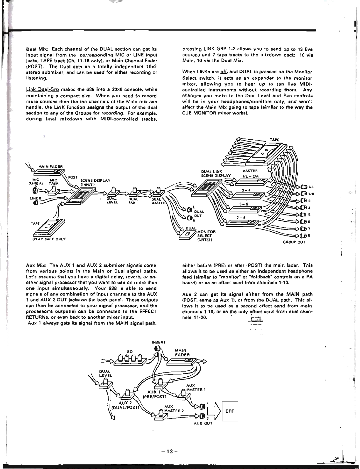
Dual
Mil(:
Each channel
of
the
DUAL
section can
get
its
input
signal
from
the
corresponding
MIC
or
LINE
input
jacks. TAPE track (Ch. 11-18
only),
or
Main
Channel Fader
(POST).
The
Dual
acts
as a
totally
independent
101(2
stereo
lIubmlxsr,
and
can
be
used
for
either
recording
or
listening.
Wok
Dual-Grp
makes
the
688
into
a 20x8 console,
while
maintainIng
a
compact
sIze.
When
you
need
to
racord
more
sources
than
the
ten
channels
of
the
Main
mix
con
handle,
the
UNK
function
assigns
the
output
of
the
dual
Mction
to
any
of
the
Groups
for
recording.
For
example,
during
final
mixdown
with
MIDI-controlled
tracks,
Aux
Mix:
The
AUX
1
and
AUX
2
submixer
signals
come
from
various
points
in
the
Main
or
Dual
signal
paths.
Let's assume
that
you
have
a
digital
delay, reverb,
or
an-
other
signal processor
that
you
want
to
use
on
more
than
one
input
simultaneously.
Your
688
is
able
to
send
signals
of
any
combination
of
Input
channels
to
the
AUX
1
and
AUX
2 OUT
Jacks
on
the back panel. These
outputs
can
then
be
connected
to
your
signal
processor,
and
the
processor's
output(s)
can
be
connected
to
the
EFFECT
RETURNs,
or
even beck
to
another
mixer
input.
Aux
1
always
gets
Its
signal
from
the
MAIN
signal
path,
either
before
(PRE)
or
aft~r
IPOST) the
main
fader. ThIs
allowa
It
to
be
used as
either
an
independent
headphone
feed
Isimllar
to
"montior"
or
"foldback"
controls
on
a
PA
board)
or
8S
an
effect
send
from
channels 1-10.
Aux
2 can
get
its
signal
either
from
the
MAIN
path
(POST,
same
as
Aux
1),
or
from
the
DUAL
path.
This
al-
lows
it
to
be used
89
a second
effect
send
from
main
channels 1-10,
or
es the
onlv
effect
send
from
dual chan-
nels 11·20. '
j:~
-13-
e
points
the fly·,
the
two
·0000·
·0000·,
n
of
the
~ari8ble
mode
to
'LAY
and
r
MEMO
rt in both
nultitrack
track;
for
lea~y,
its
tion and
x noise
ormallV,
I MEMO
nd
clear
s you
to
-articular
='
,.\J
-14-
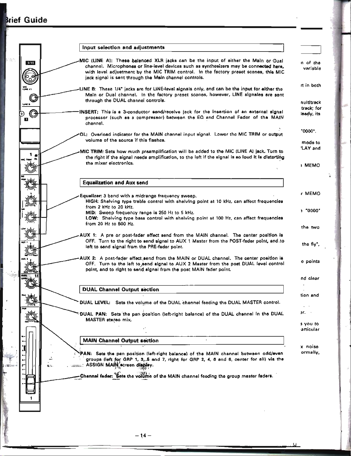
AUX
2: A post-fa(jer effect,send
from
the
MAIN
or
DUAL channel. The center positlon ia
OFF.
Turn
to
the
left
to
,send signal
to
AUX
2
Muter
from
the
post DUAL level control
point, and
to
right
to
seri~,
algnal from the
post
MAIN fader point.
AUX
1: A pre
or
post-fader effect send
from
the MAIN channel. The center position is
OFF.
Turn
to
the
right
to
send signal
to
AUX
1 Master from the POST-fader point, and,to
left
to
send signal from the PRE-fader point.
Equalizer:
3 band
with
a midrange frequency sweep.
HIGH; Shelving type treble control
with
shelving
point
at 10
kHz,
can affect frequencies
from
2
kHz
to
20
kHz.
MID: Sweep frequency range
is
250
Hz
to
5
kHz.
LOW:
Shelving type bass
control
with shelving point at 100
Hz,
can affect frequencies
from
20
Hz
to
500
Hz.
OL: Overload indicator
for
the MAIN channel
input
signal. Lower the MIC TRIM
or
output
volume
of
the
source
if
this flashes.
MIC
TRIM: Sets
how
much preampHfication
will
be added
to
the MIC IUNE
Al
jack. Turn
to
the
right
if
the siglUll needs amplification,
to
the
left
if
the signal is
90
loud
it
ia distorting
the
mixer
electronIcs.
..
UNE
B:
These 1/4· jacks are
for
LINE·level signals only, and can be the
input
for
either the
Main
or
Dual channel. In
the
factory preset scenes, however, LINE slgnales are sent
through the DUAL channel controls.
MIC
IUNE
AI:
These balanced
XLR
jacks can be the
input
of
either the
Main
or
-Dual
channel. Microphones
or
line-level devices such
as
synthesizers
may
be connected here,
with
level
adjustment
by the MIC TRIM control.
In
the factory preset scenes,
this
MIC
jack signal is sent through the Main channel controls.
IDUAL Channel
Output
section
I
MAIN
Channel
Output
seCtion
IEqualization and Auxsend
I
Input
selection
and
adjustments
DUAL
LEVEL:
Sets the vol':l,me
of
the DUAL channel feeding the DUAL MASTER control.
,DUAL
PAN:
Sets'the
pan position (left-right balance)
of
the DUAL channel In the DUAL
MASTER stereo mix.
PAN:
Sets
the
pan position
!left-right
balaneel
of
the
MAiN
chennel between odd/even
groups
!left
,tor
GRP
1, 3,_6 and 7,
right
for
GRP
2,
4,
6 end
B,
center
for
aliI via the
• ASSIGN
MAlNt~reen
dl*}~Y.
,,'"
'Mi
-
__
~h.nnel
f.d.,.~~
the
volume
of
the MAIN channel feeding the
group
master faders,
~I-
---INSERT:
This is a 3-conductor send/receive jack
for
the in&ertion
of
an
external signal
processor (such
as a compressor) between
the
EQ
and Channel Fader
of
the
MAIN
channel. '
:1
rief
Guide
I
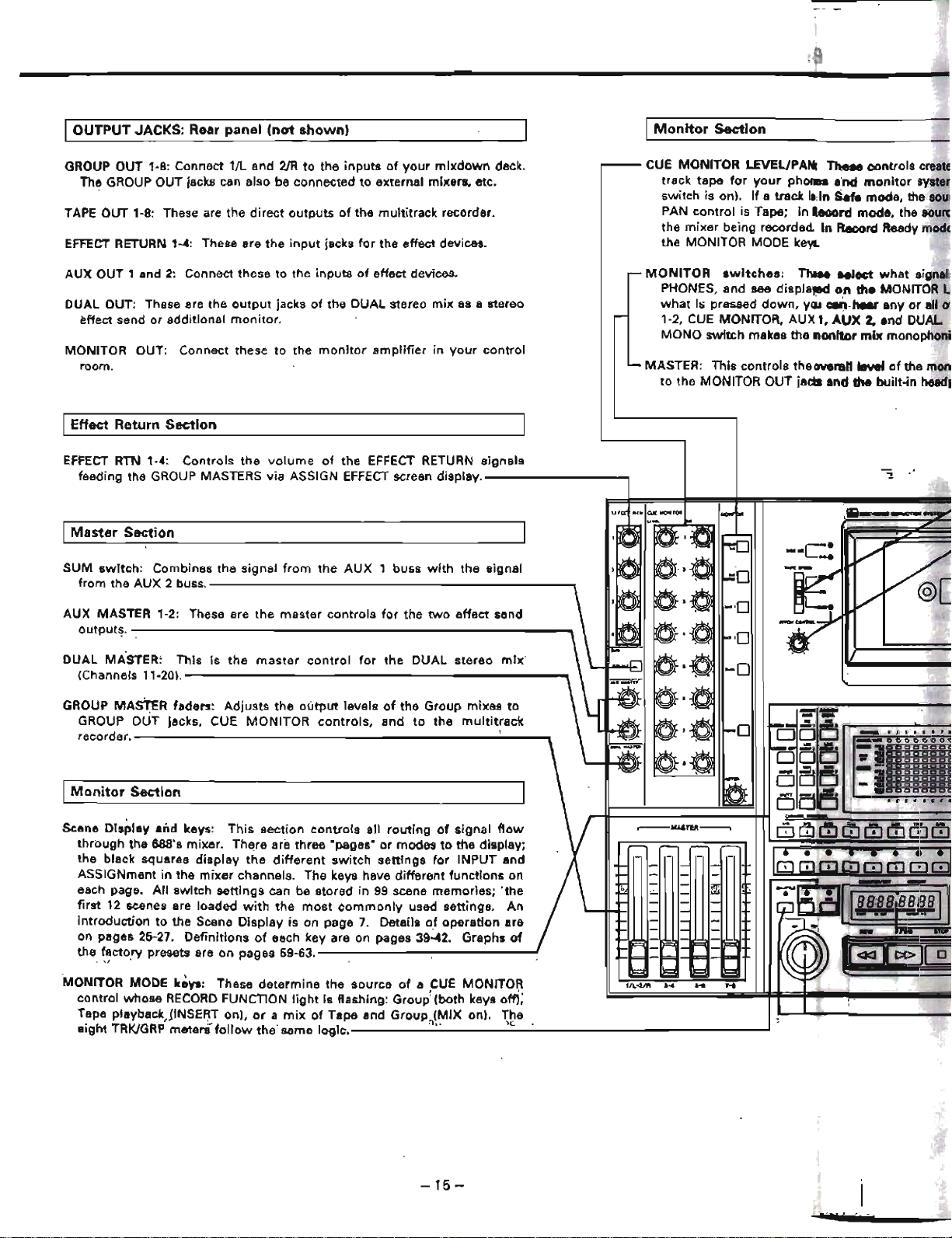
OUTPUT
JACKS: Rear
panel
(not
shown)
I
Monitor
Section
GROUP OUT 1-8: Connect 1/L and
2JR
to
the
inputs
of
your
mixdown
deck.
The GROUP OUT jacks can also be connected
to
external mixers, etc.
TAPE
OUT 1-8: These are the
direct
outputs
of
the multitrack recorder.
EFFECT
RETURN 1-4: These are
the
input
jacks
for
the effect devices.
AUX OUT 1
and
2:
Connect these to the
inputs
of
effect devices.
DUAL OUT: These are the
output
jacks
of
the DUAL stereo
mix
as a stereo
effect send
or
additional
monitor.
MONITOR OUT: Connect these
to
the
monitor
amplifier
in
your
control
room.
IEffect Return
Section
EFFECT
RTN 1-4:
Controls
the
volume
of
the EFFECT RETURN
signals
feeding the GROUP MASTERS via ASSIGN
EFFECT
screen
display.--------....,
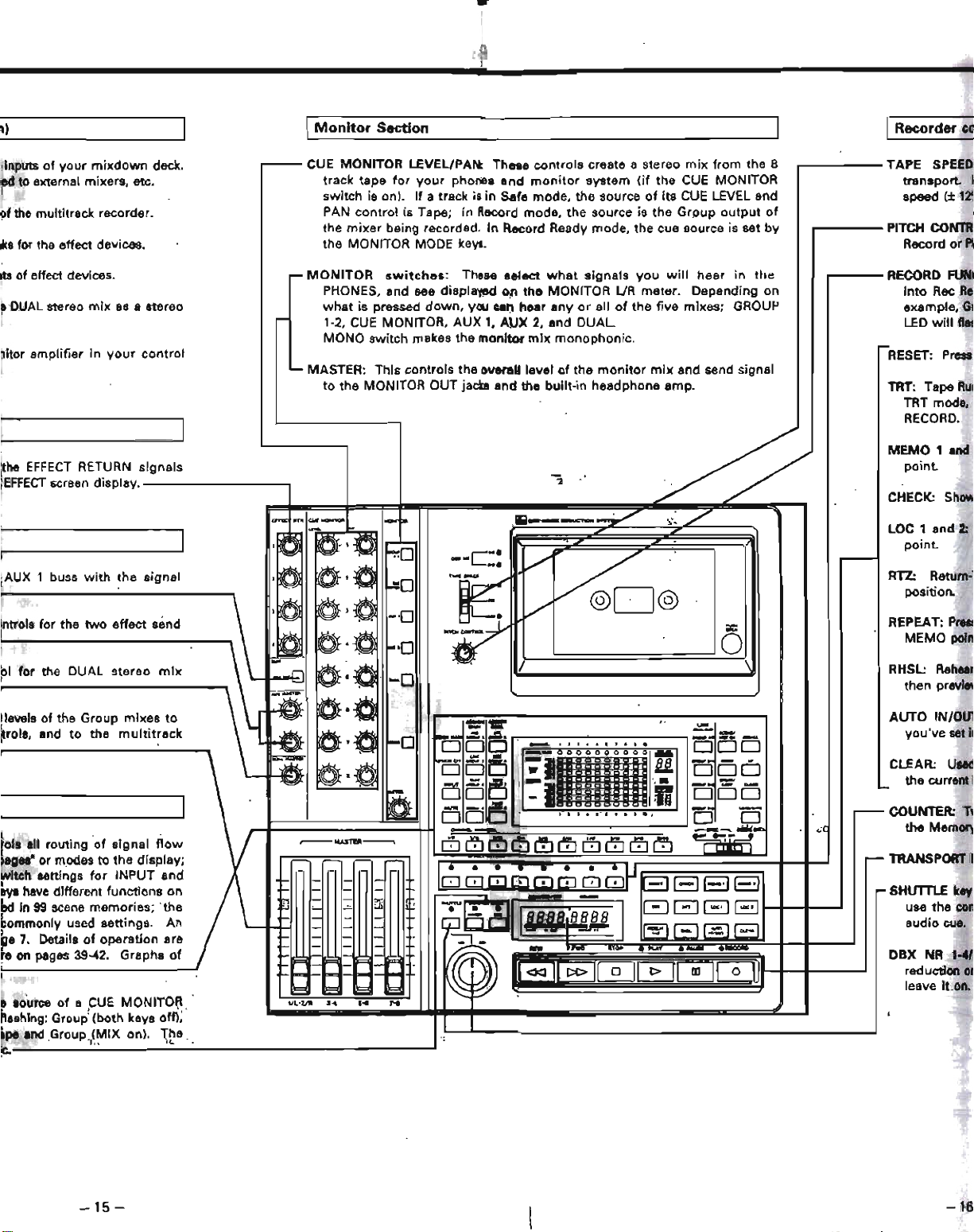
CUE MONITOR LEVEL/PArt TheM
controls
creatE
track tape
for
your
phone.
end
monitor
syste
switch is on).
If
a track
i,
in
Sefe mode, the
sou
PAN
control
is Tape;
in
.ecord
mode. the
SOUni
the
mixer
being recorded.
In
Record Ready
modE
the MONITOR MODE
keys.
MONITOR
switches:
The
....
Iect
what
signel.
PHONES. and see displaJllld
on
the
MONITOR
what
hi
pressed
down,
yll.l
can
hear
any
or
all 0\
1-2.
CUE
MONITOR, AU)( "
AUX
2,
end DUAL
MONO switch makes the
nonitor
mix
monophoni
MASTER: This
controls
the overall level
of
the mon
to the MONITOR OUT jacbl and the btJilt-in headl
I
Master
Section
SUM
switch:
Combines the signal
from
the
AUX
buss
with
the
signal
from the
AUX
2 buss.
----------------------,
AUX MASTER 1-2: These are the
master
controls
for
the
two
effect
send
outputs.
--------------------------_
DUAL
MASTER:
This
is
the
master
control
for
the DUAL
stereo
mix'
(Channels
11-20).-----------------------.,
GROUP MAsTER faders:
Adjusts
the
output
levels
of
the Group mixes
to
GROUP OUT jacks. CUE
MONITOR
controls.
and
to
the
multitrack
recorder.----------------------..;..--'"
I
Monitor
Section
Scene
Dls~ley
and
keys:
This
section
controls
all
routing
of
signal
flow
through
the 688's mixer.
ThE!re
are three "pages·
or
modes
to
the display;
the black squares
display
the
different
switch
settings
for
INPUT and
ASSIGNment in
the
mixer
channels. The keys have different functions on
each page.
All
switch
settings
can be stored in
99
scene memories;
'the
first
12
scenes are loaded
with
the
most
commonly
used settings, An
introduction
to
the Scene
Display
is on page
7.
Details
of
operation
are
on pages 25-27.
Definitions
of
each key are on pages
39~2.
Graphs
of
the_
~~cto.ry
presets are on pages 59-63.
.1
MONITOR MODE
ke.,.:
These
determine
the
source
of
a CUE MONITOR
control whose
RECORD
FUNCTION
light
is flashing:
Group~
(both keys
om;'
Tape playback)INSERT on).
or
a mi)(
of
Tape and
Group.(MIX
on), The.
eight TRK/GRP meteni'
follow
the
same
logic.-----·,-,·----...;,'<·---------------
....
-15
-
1iIiiiI--~
.........
f
••
'.
:;jlllO
0 0 0
000
:1
o
mpr
I)
I
Monitor
Section
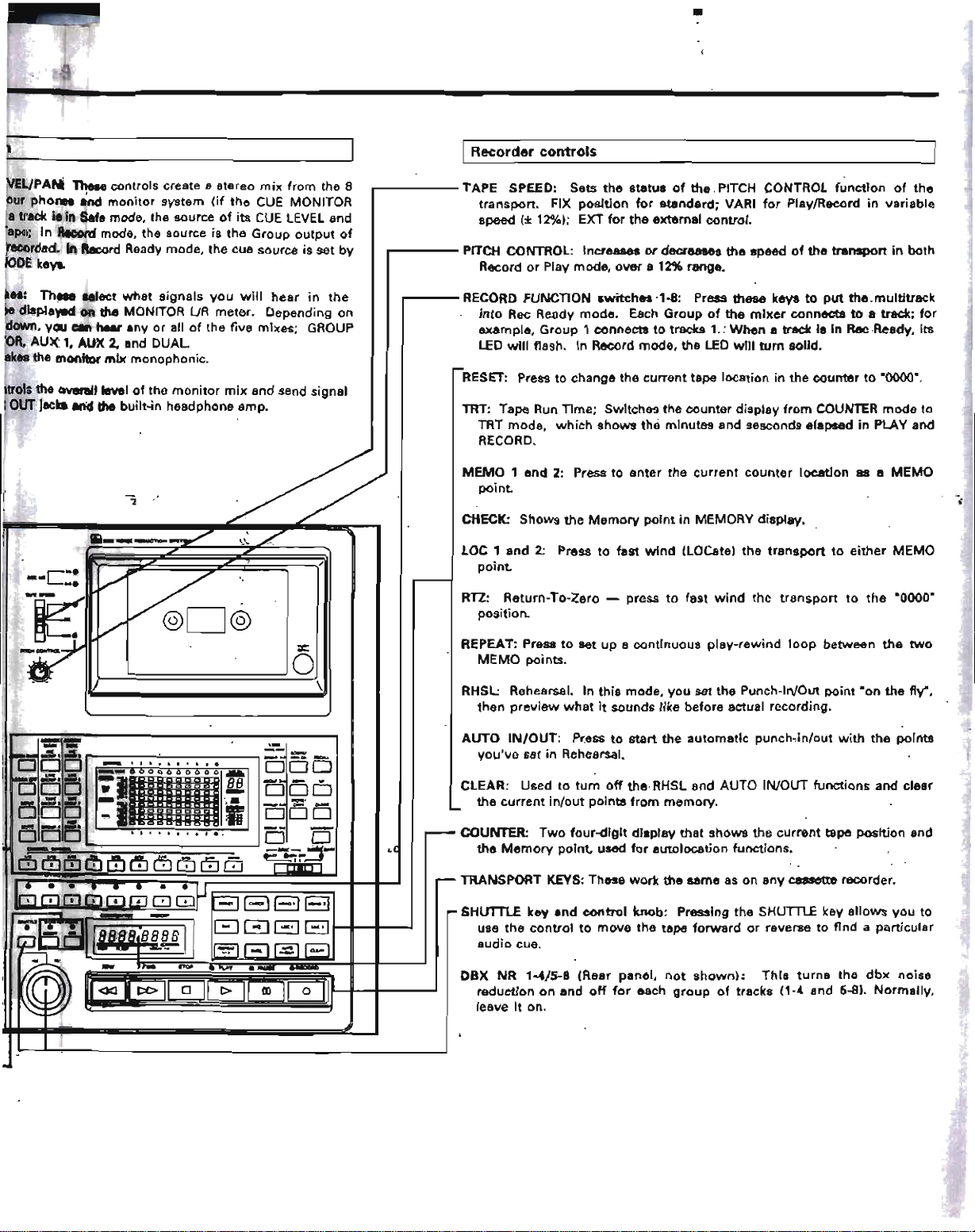
IRecorder ell
COUNTER:
T~
the
Memory
RTZ:
Return:
position.
AUTO
IN/OU1
you've set
II
CLEAR:
Used
the current i
RHSL:
Rehear
then previ8\
LOC
1
and
2:
point.
SHUTTLf
key
use the
con
audio
cue.
RECORD
FUM
into
Rec
Re;
example.
GI
LED
will
fles
REPEAT:PrtSI
MEMO
poin
RESET:
Press
TRANSPORT
~
DBX NR 1-4/
reduction
01
leave
it
on.
CHECK:
Show
TRT:
Tape
RUI
TRT mode.
RECORD.
MEMO
t and
point.
PITCH
CONTRI
Record
or
PI
TAPE
SPEED
transport
I
speed
(±
1~
h 8
. f
CUE
MONITOR
LEVel/PAN:
Th
d k
'd
Inputs 0
your
mix
own
ec .
....--
ese
contro
s create a stereo
miX
rom t e
d to external mixers. etc.
track tape
for
your
phones and
monitor
system
(if
the
CUE
MONITOR
switch
is on).
If a track
is
in
Safe mode, the source
of
its
CUE
LEVEL and
~f
the multitrack recorder.
PAN
control
is Tape;
in
Record mode,
the
source is
the
Group
output
of
the
mixer
being recorded.
In
Record Ready mode. the cue source is set
by
~s
for the effect
devices~
the MONITOR MODE
keva.
itS of effect devices.
,...MONITOR
switches:
These select
what
signats
you
will
hear
in
the
PHONES, and see displayed
on
the
MONITOR lJR meter. Depending on
8
DUAL
stereo
mix
as a stereo
what
is pressed
down,
you
~n
Iilear
any
or
all
of
the
five mixes; GROUP
-
1-2,
CUE
MONITOR, AUX 1,
AUX
2, and
DUAL
MONO switch makes the monitor
mix
monophonic.
-
~itor
amplifier in
your
control
.... MASTER: This controls the overall level
(If
the
monitor
mix
and send signal
to
the
MONITOR OUT jacm and the
built-in
headphone amp.
I
y;/
the
EFFECT
RETURN signals
EFFECT
$Creen
display.
"'1!
--.
"
"'""
...
""'-
I-po.
~
___
--=ndIrt~
~~
./
I
,a
~-
~-,e
/
~o
eM.
-~
./
~@
-
,0
a·e
w.
AUX 1
buss
with
the signal
f-=O
J
·0
.~
e
/
C",
.
-'0
,ntrols for the
two
effect
send
.~
I~·e
0
~
1--0
-
~~:O-
/
01
for the DUAL stereo
mix
.r>
-0
-
:w~
a·tJ
levels
of
the Group
mixes
to
~
--
.-
trois, and to the
multitrack
-?J
0;-;0
-
-
-
-0
'"!:.-
..:..
Ei
-~
aD
~
~
0 0
_ •
.11
•••
'
....
0
...
Ei
--
"II
0'"
--..:Ii
-01·10
~O.'
0
':'1
BB
-..!:'
DO
1:..-
0
cccce
-
0
~~
0
-
~
:'1
c
'
..
-~
-
E:i
•
DO
-
I
OL
co
cae
0
DEi
r5
t
......
'.
,
••
_:
.".
0
0
-
-
......
...
-~--..~
...
..:C
rols all routing
of
signal
flow
~MASTEIII-----,
dJ(1J (!J
(~ll!)
OJ
0
CfJ
Q]
Q)
llfi
lag
..
"or modes
to
the
display;
,.....
witch settings
for
INPUT and
~[
II·
• • .
..
• •
.)~
-
-
0171080008
SElBEl
Ilyl
have
dIfferent
functions
on
l~
- -
"""
-
- -
ed in
99
scene memories;
'the
1
;-
~FJr!jI
]
c=:J
G
BEl
-
-
commonly used settings.
An
-
-
~
-
uu.~BB8
f-
-
(
.~
.....
~G.
ge
7.
Details
of
operation are
I-
-
- -
re
on
pages 39-42.
Graphs
of
E
~
II:
n:
1ci:ltiJ0011
-
-
~
E
~
Il=
8 .ouree
of
a
;CUE
MONITOI;\.
'/L'Z/IlI
...
.
...
H
n89hing: Group' (both keys off);
I
lpe
end
Group.<MIX on). The
,
".
"L
C.
-
15-
-16
EUPAN
TheM controls create a stereo
mix
from the 8
ur
pho
...
and
monitor
system
(if
the
CUE
MONITOR
a track
i.
in
Safe mode, the source
of
its
CUE
lEVEL and
ape;
in
Record
mode, the source
is
the
Group
output
of
ecorded.
In
Record Ready mode, the cue source is set
by
lODE
keys.
•
IRecorder
controls
.------TAPE
SPEED: Sets
the
status
of
the
PITCH CONTROL
function
of
the
transport.
FIX
position
for
standard;
VARI
for
Play/Record
in
variable
speed
(±
12%1; EXT
for
the
external control.
...------
PITCH CONTROL: Increases
or
decreases
the
speed
of
the
transport
in
both
Record
or
Play mode,
over
a 12% range•
••
:
Th
.....
Ieet
what
signals
you
will
hear
in
the
displav-d on the MONITOR UR meter. Depending on
down, you c.n
hur
any or all
of
the five mixes; GROUP
OR,
AUX 1, AUX
2.
and DUAL.
kes
the monitor
mix
monophonic.
..-----
RECORD
FUNCnONswitches
-'-8:
Press these keys
to
put
the
multitrack
into
Rec
Ready mode. Each
Group
of
the
mixer
connects
to
a track;
for
example, Group 1 connects
to
trac:lts
1.:
When
a track
is
In
Rae
Ready, its
LED
will
flash. In Record
mode,
the
LED
will
turn
solid.
troIs the Gvel'llllievel
of
the
monitor
mix
and send signal
OUT
jacks and the built-in headphone amp.
RHSl:
Rehearsal. In
this
mode,
you
set the Punch-In/Out
point
·on
the
fly·,
then
preview
what
it
sounds like before actual recording.
RTZ:
Return-To-Zero - press
to
fast
wind
the
transpo"
to
the
·0000·
position.
RESET:
Pre~
to change
the
current tape location in the
counter
to
·0000·.
TRT: Tape Run Time; SwItches
the
counter
display
from
COUNTER
mode
to
TRT
mode,
which
shows
the
minutes and sesconds elapsed
in
PLAY and
RECORD.
CHECK:
Shows
the
Memory
pornt
in
MEMORY display.
REPEAT: Press
to
set up a contInuous
play-rewind
loop
betwean
the
two
MEMO
points.
LOC , and 2:
Pr,ss
to
fast
wind
(LOCate) the
transport
to
either
MEMO
point.
MEMO
1 and 2: Press to
enter
the
current
counter
location
as a
MEMO
point.
,
\
=:
o
/
AUTO
IN/OUT:
Pr.ess
to
start
the
automatic
punch~in/out
with
the
points
YOU've
set
in Rehearsal.
CLEAR: Used
to
turn
off
the
RHSL and AUTO IN/OUT
functions
and clear
the
current
in/out
points
from
memory.
COUNTER:
Two
four-digit
display
that
shows
the
current
tape position and
the
Memory
point.
used
for
autolocation functions.
TRANSPORT KEYS: These
work
the
&ame as on
any
cassette recorder.
SHUTTlE
key
end
control
knob: Pressing the SHUTTLE key
allows
you
to
use
the
control
to
move
the
tape
forward
or
reverse to
find
a particular
audio
cue.
DBX
NR
'-4/5-8
(Rear panel,
not
shown):
ThIs
turns
the
dbx
noise
reduction
on
and
off
for
each
group
of
tracks (1-4 and 5-8).
Normally,
leave
It
on.

Step-BywStep
Operations
Guide:
Tracking
Following
aro
step-by-step
instructions
for
the
basic
procedures
of
the
MIDISTUDIO.
They
will
give
you
the
basic
experience
you
need
to
fully
understand
the
sections
that
explain
the
capabilities
of
the
688
in
detail,
80
you
can
customize
it
for
your
own
situation.
ISETUP
I
f
Preset
the
controls:
To
avoid
problems,
begin
with
the
power
off. Make sure
the
following
controls
are
set
•
Bring
all the
faders
down.
In
the
channels:
• Set all MIC TRIMS to
full
counter-clockwise
(7
o'clock)
•
Set
all
EQs.
AUX
1
and
2.
and
PAN
controls
(main,
dual and cue
monitorl
to
center
(12 o'clock)
In
the
master
and
monitor
section:
•
Turn
all
the
EFFECT RETURNS,
AUX
end
DUAL
MAS-
TERS,
the
CUE
MONITOR
LEVEls,
and
the
monitor
MASTER
off
(to
full
counter-clockwise
(7
o'clock))
• Put all
the
MONITOR
SWITCHES
(from
GROUP
'·2
to
MONO)
in
their
OFF
position
(up):
IRECORDING THE FIRST TRACK
Prepare
to
Record
Insert
a
cassette:
Press
on
the
cassette
door's
lower
right
hand
corner,
and
it
will
spring
open.
Insert
a
high
quality
blank
High
Bias
(Type
III tape. Close
the
door.
If
you
want
to
use
a
microphone
for
your
first
experi-
ments.
plug
it
into
the
MIC
(LINE
A)
XLR jack '/11.
If
you
want
to
use an
instrument,
plug
it
Into
the
LINE B
phone
jack
just
below
it.
Set
any
volume
controls
on
the
In-
strument
to
maximum.
In these
first
exercises
using
factory
presets, MIC
will
go
through
the
Main
channel,
and
the
LINE
instrument
will
go
through
the
Dual
channel.
Later,
you
can
alter
the
factory
presets
to
bring
LINE B
through
the
Main
chan-
nel.
but
stick
with
this
procedure
for
now.
Tum
the
POWOf'
on.
• On
the
rear
of
the
unit
set
the
DBX
switches
to
IN.
The LEOs
will
go
on
the
control
panel.
• Check
to
see
that
both
the
SYNC
"EXT"
and
"MIDI"
LEOs are
off.
Select
the
Input
and
outDut
for
the
channel
1.
On
the
numbered
CHANNEL keys,
preas
"OW
then
..
,",
This
should
make
"SCENE
01"
appear
In
the
assign
display
and
the
scene
number
will
blink:
It'a
a special
factory
praset
intended
for
recording
all
inputs
onto
track
1
(unless
your
unit
has
already
been
used
by
someone
else,
1n
which
case
you
should
S88
pp. 27
"Restoring
Factory
Presets"1.
Alternately,
you
cen
U98
the
UP/DOWN
keys
to
make
the
scene
eppear
in
the
display.
Press
the
ASSIGN
MAIN
key.
The
screen
should
look
like this:
In
the
transport
section:
•
Set
the
TAPE SPEED
to
FIX.
• Set
the
SYNC
switch
to
OFF.
Plug
in
headphones
or
monitor
amplifier
and
speakers:
Make
sure
the
headphones
are
stereo.
Inserting
any
mono
jack
Into
the
headphone
jack
shorts
out
the
head-
phone
amplifier.
If
you'd
rather
use a
monitor
speaker
setup,
connec1
the
MONITOR
OUT
jacks
on
the
back
of
the
688
to
the
In-
puts
of
your
powet'
amplifier.
~1.
12J_.I'
••
'O
_
.....
0
00000
000
0
-
_
...
1
••••••••••
n I
-
...
CJ
CJ
0 0 0
CJ
Cl
0 0 C
U
I
-'DO
Cl
DODD
Cl
0 0
....
0000000000
-'OClOOOOClOOO
-
_.
Cl
0 0
Cl
Cl
Cl Cl
° ° 0
--
-,
Cl
°
CJ
0 0
CJ
0 0
CJ
0
_
..
_.
0 0 ° 0 0 CJ °
CJ
° 0
This
ahows
that
all
Main
channels
and
the
Dual
output
are
routed
to
Group
1.
If
you
are
usIng
a
microphone,
make sure
the
Main
pen
pot
ia
turned
to
the
center,
or
to
the
left.
If
you
are
using
an
Instrument.
do
the
same
for
the
Dual pan
pot.
If
the
pan
pots
are
turned
hard
right,
they
can't
send
signal
to
Grp
1
even
though
they're
assIgned
there.
2.
Press
RECALL
The
scene
number
will
stop
blinking
and
Scene
0'
is
activated.
To
racall
scenes
you
can
optionally
use
the
RC~OP
footswitch.
When
connected
to
the
REMOTE
UP/DOWN
jack
on
the
front
snd
pressed.
it
has
the
same
effect
8S
pressing
UPJDOWN
and
then
RECALL
3.
Press
the
INPUT
key
and
make
sure
the
8COne
looks
like thIs;
~l
11
••
SI'.,tO
--
000
000
00
00
-
..:
..........
n
I
-
...
CJOOOCJOCJCJOCI
U
I
_OCOClOOClOClCJ
-
oocoOCJoooc··
...
,?oOCJogcOClCJ
-
~
..........
--
-
_oCJooCJpoCJoCJ
-
..
....,.DOOODCJOr.::lCJD
• ,
~
4 5 • ,
..
• 10
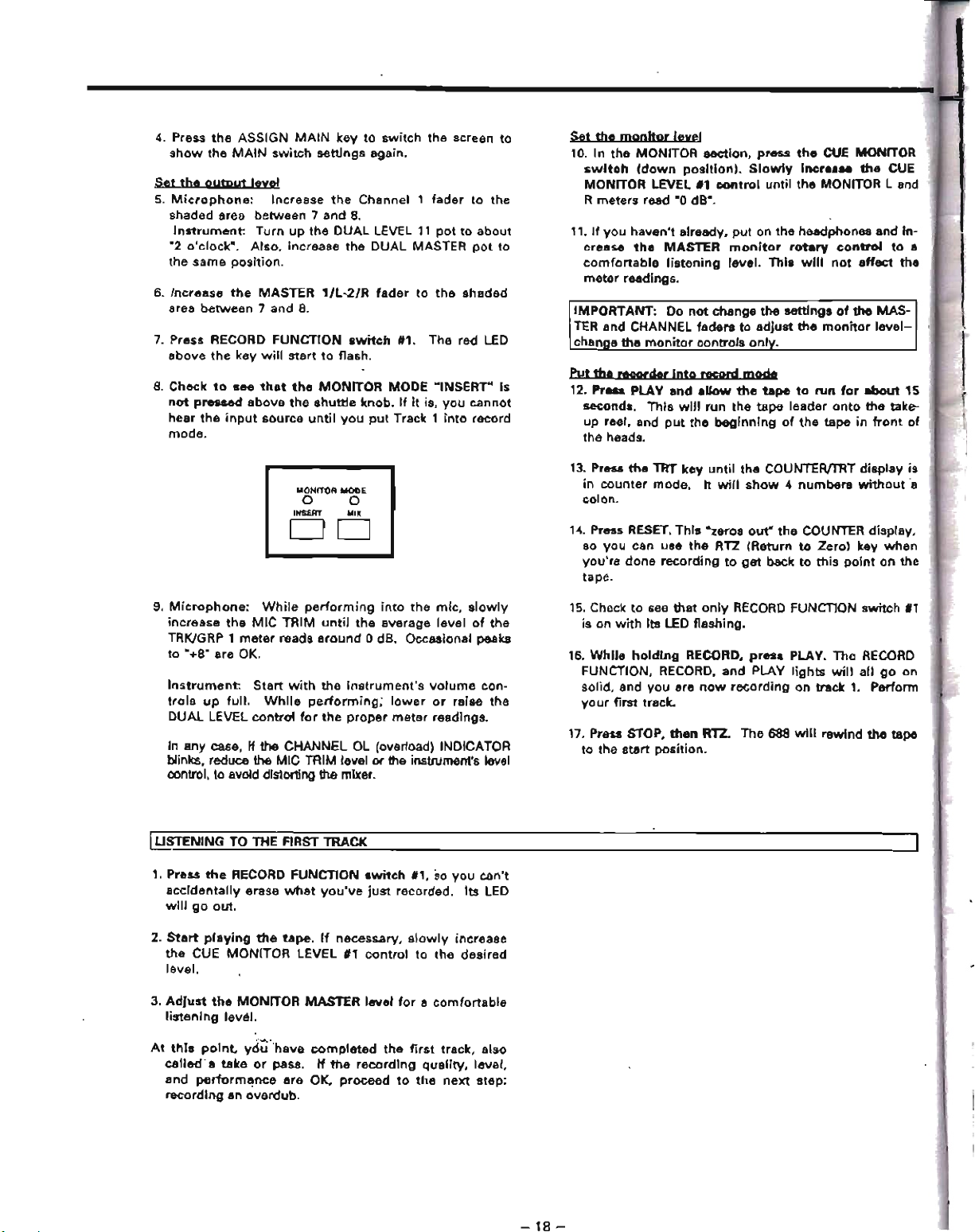
4. Press
the
ASSIGN
MAIN
key
to
switch
the
screen to
show
the
MAIN
switch
settings
again.
Set
the
output
leyel
5.
Microphone:
Increase
the
Channel 1
fader
to
the
shaded area between 7
and
8.
Instrument:
Turn
up
the
DUAL
lEVEL
11
pot
to
about
"2
o'clock".
Also.
increase
the
DUAL
MASTER
pot
to
the
same
position.
6.
Increase
the
MASTER
1/L-2/R
fader
to
the
shaded
area
between
7
and
8.
7.
Press RECORD
FUNCTION
switch
1#1.
The
red LED
above
the
key
will
start
to
flash.
8.
Check
to
see
that
the
MONITOR
MODE
"INSERT"
Is
not
pressed
above
the
shuttle
knob.
If
it is,
you
cannot
hear
the
input
source
until
you
put
Track 1
into
record
mode.
MONITOR
MODE
o 0
INSERT
MI)(
DO
9.
Microphone:
While
performing
into
the
mic,
slowly
increase
the
MIC
TRIM
until
the
average
level
of
the
TRKlGRP 1
meter
reads
around
0 dB. Occasional
peaks
to
"+8"
are OK.
Instrument:
Start
with
the
instrument's
volume
con-
trols
up
full.
While
performing;
lower
or
raise
the
DUAL
LEVEL
control
for
the
proper
meter
readings.
In
any case, If the CHANNEL OL (overload) INDICATOR
blinks, reduce the MIC TRIM level
Dr
the instrumenfs level
control, to avoid distorting
the mixer.
l1i:~ENING
TO
THE FIRST TRACK
1. Press
the
RECORD FUNCTION
switch
fl,
so
you
can't
accidentally
erase
what
you've
just
recorded.
Its
lEO
will
go
out.
2.
Start
playing
the
tape.
If
necessary,
slowly
increase
the
CUE
MONITOR
LEVEL
'1
control
to
the
desired
level.
3.
AdJust
tho
MONITOR
MASTER
level
for
a
comfortable
listening
level.
At
this
point
yd~'have
~mpleted
the
first
track,
also
called'.
take
or
pass.
If
the
recording
quality,
level,
and
perlorm~nce
are
OK,
proceed
to
the
next
step;
recording
an
overdub.
-
18-
Set
the
monitor
leyel
10.
In
the
MONITOR
section,
press
the
CUE MONITOR
switch
(down
position
I.
Slowly
incre
...
the
CUE
MONITOR LEVEL
'1
control
until
the
MONITOR
Land
R
meters
read "0 dB-.
11.
If
you
haven't
already,
put
on
the
headphones and In-
crease
the
MASTER
monitor
rotary
control
to
a
comfortable
listening
level.
This
will
not
affect
the
meter
readings.
IMPORTANT: Do
not
change
the
settings
of
the
MAS-
TER
and
CHANNEL faders
to
adjust
the
monitor
level-
change
the
monitor
controls
onlv.
put
th'
recorder
Into
record
mode
12. Pre
..
PLAY
and
ellow
the
tape
to
run
for
ebout
15
seconds.
This
witl
run
the
tape
leader
onto
the
take-
up
reer, and
put
the
beginning
of
the
tape
in
front
of
the heads.
13. Press
the
TAT
key
until
the
COUNTER/TRT
display
is
in
counter
mode.
It
will
show
4
numbers
without
'a
colon.
14. Pross RESET.
This
·zeros
out"
the
COUNTER display.
so
you
can use
the
RTZ
(Return
to
Zerol
key
when
you're
done
recording
to
get
back
to
this
point
on
the
tape.
15. Check
to
see
that
only
RECORD
FUNcnON
switch
'1
is on
with
its
LED flashing.
16.
While
holding
RECORD.
press
PLAY.
The
RECORD
FUNCTION, RECORD,
and
PLAY
lights
will
all
go
on
solid. and
you
are
now
recording
on track
1.
Perform
yo
ur
first track.
17. Press STOP.
then
RTZ.
The
688
will
rewind
the
tape
to
the
start
position.

Step-By-Step
Operations
Guide:
Overdubbing
Overdubbing
is
recording
new
tracks
while
listening
to
previously
recorded
tracks
with
the
CUE MONITOR sec-
tion.
In
this
quick
tutorial.
we're
going
to
continue
using
the
factory'
preset
Scene
settings
as
our
basis.
RQute
the
source
to
Track 2
1.
SCENE: On
the
numbered
CHANNEL keys, prB6S
"0"
then
"2".
This
should
make
"SCENE 02"
appear
in
the
assign
display
and
the
scene
number
will
blink.
Then
press
RECALL. The ASSIGN
MAIN
Scr"n
should
look
like
this:
OoI.....
NCL.
, J J ..
:I
• , • • 10
,.,..."""
0
000000000
-
-
_.
a
c::J
a a
c::J
c::J
CJ
c::J
0
c::J
02
-
...
,
..........
-,
CJ
c::J
0 a
c::J c::J
a
c::J
0 0
""'·0
0 0 0 CJ 0 0 0
CJ
0
-,
00
CJ CJ CJ 0 CJ CJ a 0
-
·'00
CJ 0 0
00000
"",.-
_T
0000000000
_
..
foftl·D
0 a
Cl
0 0 CJ CJ
0·0
, t .) .. $ • , • I
'0
This
shows
that
all
channels
are
assigned
to
Group
2.
Make
sure
the
PAN
control
of
any
channel
you
wish
to
record
is
in
the
center,
or
to
the
right.
You
do
not
need
to
repatch
the
microphone
or
Instrument
you
used
in
the
first
exercise.
if
you're
using
the
same
source
for
the
overdub.
Set
the
output
level
This
is
the
same
procedure as in recording
the
first
track..
3.
Press RECORD
FUNCTION
switch
112.
The
red LED
above
the
key
will
start
to
flash.
Make
sure
all
other
RECORD FUNCTION
switch
are OFF.
NOTE:
If
you
want
to
record
different
sources
for
the
overdub,
set
their
levels as
YQU
did
In
Steps
5
and
9
on
the
previous
page.
4. Play
the
instrument
or
speak intQ
the
microphone,
to
check
that
the
TRK/GRP 2
meter
reads
in
the
middle,
averaging
around
"0 dB",
and
the
channel's
OL
indicator
is
only
occasionally
flashing.
If
necessary,
lower
the
MASTER 1/l-21R fader.
Set
tbe
monitor
level
Monitoring
is
what
makes
overdubbing
different
from
tracking.
You
need
tQ
set
the
levels
of
the
first
track
and
your
live
instrument
in
the
cue
monitor,
without
disturb-
ing
the
settings
that
control
how
much
goes
to
the
tape
recorder. (See p.
e,
"The
three
steps
tQ
multitrack".)
5. Check
to
see
that
the
MONITOR MODE INSERT
light
is
OFF.
Make
sure
CUE MONITOR
is
the
only
switch
pressed
in
the
MONITOR section.
(For
details
of
how
INSERT
and
MIX
affect
the
CUE MONITOR,
s"
page
43.)
6.
While
playing
your
instrument.
slowty
Increase
the
CUE
MONITOR
LEVEL '2
control
for
"0
dB"
on
the
MONITOR meters.
7.
If
you
haven't
already,
put
on
the
headphones
and
in-
crea.se
the
MASTER
monitor
rotary
control
tQ
a
com-
fortable
li3tening
level.
8. Press PLA V
and
increase
tt1e CUE
MONITOR
LEVEL
.1
contrQI
to
hear
the
playback
of
track
1 in.
your
headphones,
along
with
your
live
instrument.
9. AdJust
the
CUE
MONITOR
LEVEL
or
PAN
11
and
112
until
you
hear
the
balance
you
want
in
your
head-
phones.
10.
Pre
..
RTZ
to
rewind
the
tape
to
the
start
position.
Put
the
recorder
Into
record
mode
11.
While
holding
RECORD, press
PLAY.
The
RECORD
FUNCTION, RECORD,
and
PLAY
lights
will
all
go
on
solid,
and
you
are
now
recording
on
track
two.
Perform
your
first
overdub.
12.
Press
STOP, tt1en·RTZ.
The
688
will
rewind
the
tape
to
the
start
position.
Wlten
to
the
oyerdyb
13. Press
the
RECORD FUNCTION switch
'2,
&0
you
can't
accidentally
erase
what
you've
just
recorded.
Its LED
will
go
out.
14. Press PLAY. You
will
hear
the
pl<tyback
of
both
track
,
and
2. You
can
re-adjuat
the
CUE MONITOR LEVEL
and
PAN
cQntrols
to
get
a
8tereo
monitor
mix
Qf
the
fi
rst
two
tracks.
Perfonning
overdubs
3
to
8
Tracks 3
thru
8 can
be
recorded
using
almQst
the
Identical
procedure
aa
above.
The
differences
are:
•
Different
preset
scenes (03
thru
08)
•
Different
RECORD FUNCTION
switches
•
Use
MASTER
fader
3-4,
5-6
or
7-8
to
set
the
record
levels
• Use
cue
MONITOR LEVEUPAN
controls
2-8
to
set
the
monitor
levels
You can
connect
new
sources
to
any
empty
MIC
or
UNE
jacka
as
long
as
you
use
the
factory
preset
scenes 03-09
for
the
each
assign
all
channels
to
one
group
like
the
presets
01 and 02. '
To
record
on
more
thin
QDe
track
limultaDtoysly,
you
will
probably
have
to
create
YQur
own
acen
..
following
the
procedure
on
pages
23·26.
But
to
help
you
get
started,
here
are
two
shortcuts:
Factory
Sc:ene 10
assigns
one
MIC
jack
to
each track (Ch.
1
to
GRP 1, Ch. 6
to
GRP 5 etc.).
Just
patch
the
mic
Into
the
same
channel
as
the
track
you
want
to
record.
You
can
record
eight
mic
sources, each
on
a separate track.
Uslng~Scene
11.
which
assigns
every
input
to
1111
eight
Groups
lit
once,
you
can record
on
any
odd
lind
even
track
using
the PAN
controls
for
assignment.
 Loading...