


424@$
OWNER’S MANUAL |
3D0023100A |

Table Of Contents
Safety Instructions |
3 |
Introduction |
4 |
The Recording System |
5 |
The three steps to multitrack |
5 |
Understanding the Mixer |
6-7 |
Signal flow in the 424 MKIII mixer |
6 |
Tape cue monitor system |
7 |
Multitrack Cassette Recorder |
8 |
Track Format and Tape Recommendations |
9-10 |
PORTASTUDIO 424 MKIII Brief Guide |
11-14 |
Step-By-Step Operations Guide |
15-24 |
Let's try the 424 MKIII mixer |
15 |
How to record on track 1 |
16 |
Track 1 playback through TAPE CUE |
18 |
How to make an overdub on track 2 |
19 |
How to record tracks 3 and 4 |
20 |
How to record many sources onto a |
|
single track |
20 |
How to record a mix onto two tracks |
|
simultaneously |
21 |
Recording on more than two tracks |
|
simultaneously : DIRECT |
22 |
How to mix down |
23 |
Using Memory Location Points |
25-26 |
Loading MEMO points |
25 |
Locating the tape |
26 |
Repeat Play |
27 |
PUNCH-IN or INSERT Recording |
28-32 |
Preliminary |
28 |
Rehearsal and auto in/out procedures |
29 |
Manual punch-in |
31 |
Bouncing Tracks (Ping-Pong) |
33-34 |
Ping-pong procedure |
33 |
Using Effects with the |
|
PORTASTUDIO 424 MKIII |
35-36 |
Setting effect send levels |
35 |
Setting the output level of effect devices |
35 |
Setting the mix/balance control |
|
on effect devices |
35 |
How to connect your effects devices |
36 |
Syncing MIDI-Tape—Using the |
|
TASCAM MTS-30 |
37 |
Troubleshooting |
38 |
Features and Controls |
39-45 |
424 MKIII Mixer |
|
Input section |
40 |
Stereo input section |
41 |
Monitor section |
41 |
Master section |
41 |
Output section |
41 |
424 MKIII Recorder |
|
Cassette loading and dbx system |
42 |
Transport controls |
43 |
Track controls |
44 |
Displays |
44 |
Autolocators |
44 |
Optional Accessories |
47 |
Care and Maintenance |
48-49 |
How the dbx Works |
49 |
Specifications |
50-52 |
Block Diagram |
53-54 |
Level Diagram |
55 |
"© Copyright 1998, TEAC Corporation"
All rights reserved under international and Pan American copyright conventions.
This book may not be reproduced in whole or in part, by mimeograph or any other means, without permission.
"The following marking is located on the bottom of the unit."
CAUTION
RISK OF ELECTRIC SHOCK
DO NOT OPEN
CAUTION: TO REDUCE THE RISK OF ELECTRIC SHOCK, DO NOT REMOVE COVER (OR BACK). NO USER-SERVICEABLE PARTS INSIDE. REFER SERVICING TO QUALIFIED SERVICE PERSONNEL.
The lightning flash with arrowhead symbol, within equilateral triangle, is intended to alert the user to the presence of uninsulated "dangerous voltage" within the product's enclosure that may be of sufficient magnitude to constitute a risk of electric shock to person.
The exclamation point within an equilateral triangle is intended to alert the user to the presence of important operating and maintenance (servicing) instructions in the literature accompanying the appliance.
This appliance has a serial number located on the rear panel. Please record the model number and serial number and retain them for your records.
Model number Serial number
WARNING: TO PRIVENT FIRE OR SHOCK HAZARD, DO NOT EXPOSE THIS APPLIANCE TO RAIN OR MOISTURE.
2

Safety Instructions
CAUTION:
•Read all of these Instructions.
•Save these Instructions for later use.
•Follow all Warnings and Instructions marked on the audio equipment.
1)Read instructions — All the safety and operating instructions should be read before the product is operated.
2)Retain instructions — The safety and operating instructions should be retained for future reference.
3)Heed Warnings — All warnings on the product and in the operating instructions should be adhered to.
4)Follow instructions — All operating and use instructions shoud be followed.
5)Cleaning — Unplug this product from the wall outlet before cleaning. Do not use liquid cleaners or aerosol cleaners. Use a damp cloth for cleaning.
6)Attachments — Do not use attachments not recommended by the product manufacturer as they may cause hazards.
7)Water and Moisture — Do not use this product near water _ for example, near a bath tub, wash bowl, kitchen sink, or laundry tub; in a wet basement; or near a swimming pool; and the like.
8)Accessories — Do not place this product on an unstable cart, stand, tripod, bracket, or table. The product may fall, causing serious injury to a child or adult, and serious damage to the product. Use only with a cart, stand, tripod, bracket, or table recommended by the manufacturer, or sold with the product. Any mounting of the product should follow the manufacturer’s instructions, and should use a mounting accessory recommended by the manufacturer.
9)A product and cart combination should be moved with care. Quick stops, excessive force, and uneven surfaces may cause the product and cart combination to overturn.
10)Ventilation — Slots and openings in the cabinet are provided for ventilation and to ensure reliable operation of the product and to protect it from overheating, and these openings must not be blocked or covered. The openings should never be blocked by placing the product on a bed, sofa, rug, or other similar surface. This product should not be placed in a built-in installation such as a bookcase or rack unless proper ventilation is provided or the manufacturer’s instructions have been adhered to.
11)Power Sources — This product should be operated only from the type of power source indicated on the marking label. If you are not sure of the type of power supply to your home, consult your product dealer or local power company. For products intended to operate from battery power, or other sources, refer to the operating instructions.
12)Grounding or Polarization — This procuct may be equipped with a polarized alternating-current line plug (a plug having one blade wider than the other). This plug will fit into the power outlet only one way. This is a safety feature. If you are unable to insert the plug fully into the outlet, try reversing the plug. If the plug should still fail to fit, contact your electrician to replace your obsolete outlet. Do not defeat the safety purpose of the polarized plug.
13)Power-Cord Protection — Power-supply cords shoud be routed so that they are not likely to be walked on or pinched by items placed upon or against them, paying particular attention to cords at plugs, convenience receptacles, and the point where they exit from the product.
14)Outdoor Antenna Grounding — If an outside antenna or cable system is connected to the product, be sure the antenna or cable system is grounded so as to provide some protection against voltage surges and builtup static charges. Article 810 of the National Electrical Code, ANSI/NFPA 70, provides information with regard to proper grounding of the mast and supporting structure, grounding of the lead-in wire to an antenna discharge unit, size of grounding conductors, location of antenna-discharge unit, connection to grounding electrodes, and requirements for the grounding electrode.
"Note to CATV system installer:
This reminder is provided to call the CATV system installer’s attention to Section 820-40 of the NEC which provides guidelines for proper grounding and, in particular, specifies that the cable ground shall be connected to the grounding system of the building, as close to the point of cable entry as practical.
Example of Antenna Grounding as per
National Electrical Code, ANSI/NFPA 70
|
ANTENNA |
|
LEAD IN |
|
WIRE |
|
GROUND |
|
CLAMP |
|
ANTENNA |
|
DISCHARGE UNIT |
|
(NEC SECTION 810-20) |
ELECTRIC |
|
SERVICE |
GROUNDING CONDUCTORS |
EQUIPMENT |
|
|
(NEC SECTION 810-21) |
|
GROUND CLAMPS |
|
POWER SERVICE GROUNDING |
|
ELECTRODE SYSTEM |
NEC - NATIONAL ELECTRICAL CODE |
(NEC ART 250. PART H) |
|
15)Lightning — For added protection for this product during a lightning storm, or when it is left unattended and unused for long periods of time, unplug it from the wall outlet and disconnect the antenna or cable system. This will prevent damage to the product due to lightning and power-line surges.
16)Power Lines — An outside antenna system should not be located in the vicinity of overhead power lines or other electric light or power circuits, or where it can fall into such power lines or circuits. When installing an outside antenna system, extreme care should be taken to keep from touching such power lines or circuits as contact with them might be fatal.
17)Overloading — Do not overload wall outlets, extension cords, or integral convenience receptacles as this can result in risk of fire or electric shock.
18)Object and Liquid Entry — Never push objects of any kind into this product through openings as they may touch dangerous voltage points or short-out parts that could result in a fire or electric shock. Never spill liquid of any kind on the product.
19)Servicing — Do not attempt to service this product yourself as opening or removing covers may expose you to dangerous voltage or other hazards. Refer all servicing to qualified service personnel.
20)Damage Requiring Service — Unplug this product from the wall outlet and refer servicing to qualified service personnel under the following conditions:
a)when the power-supply cord or plug is damaged.
b)if liquid has been spilled, or objects have fallen into the product.
c)if the product has been exposed to rain or water.
d)if the product does not operate normally by following the operating instructions. Adjust only those controls that are covered by the operating instructions as an improper adjustment of other controls may result in damage and will often require extensive work by a qualified technician to restore the product to its normal operation.
e)if the product has been dropped or damaged in any way.
f ) when the product exhibits a distinct change in performance _ this indicates a need for service.
21)Replacement Parts — When replacement parts are required, be sure the service technician has used replacement parts specified by the manufacturer or have the same characteristics as the original part. Unauthorized substitutions may result in fire, electric shock, or other hazards.
22)Safety Check — Upon completion of any service or repairs to this product, ask the service technician to perform safety checks to determine that the product is in proper operating condition.
23)Wall or Ceiling Mouting — The product shoud be mounted to a wall or ceiling only as recommended by the manufacturer.
24)Heat — The product should be situated away from heat sources such as radiators, heat registers, stoves, or other products (including amplifiers) that produce heat.
3
Introduction
The PORTASTUDIO 424 MKIII is...
The PORTASTUDIO 424 MKIII is a 4-track "Multitrack Master" cassette tape recorder and a full-function mixer with 8 inputs/stereo outputs combined into a single workstation.
Its high audio quality and creative flexibility reflect the experience and innovation that have allowed TASCAM to earn its reputation in professional audio production fields, and its userfriendly design makes the 424 MKIII suitable for anyone, from expert to novice.
Using this manual : To get the most out of your 424 MKIII, please take the time to read through this manual. Some time spent now will keep you from overlooking some of the features that make the 424 MKIII a more creative tool. You may discover some new tricks you haven't tried before.
Use of capital letters : In general, we use all upper case type to designate a particular switch, control, jack name or label (like PAN). Transport modes and some features are described with an upper case first letter (like Record mode).
CAUTION : TO PREVENT ELECTRIC SHOCK, MATCH WIDE BLADE OF PLUG TO WIDE SLOT, FULLY INSERT
ATTENTION : POUR ÉVITER LES CHOCS ÉLECTRIQUES, INTRODUIRE LA LAME LA PLUS LARGE DE LA FICHE DANS LA BORNE CORRESPONDANTE DE LA PRISE ET POUSSER JUSQU' AU FOND.
NOTE FOR U.K. CUSTOMERS
DO NOT cut off the mains plug from this equipment. If the plug fitted is not suitable for the power points in your home or the cable is too short to reach a power point, then obtain an appropriate safety approved extension lead or consult your dealer.
If nonetheless the mains plug is cut off, remove the fuse and dispose of the plug immediately, to avoid a possible shock hazard by inadvertent connection to the mains supply.
If this product is not provided with a mains plug, or one has to be fitted, then follow the instructions given below:
IMPORTANT. DO NOT make any connection to the larger terminal which is marked with the letter E or by the safety earth symbol ç or coloured GREEN or GREEN-and-YELLOW.
The wires in the mains lead on this product are coloured in accordance with the following code:
BLUE: NEUTRAL
BROWN: LIVE
About the weld line
There is a patterned stripe-like effect on the bottom surface of the 424 unit. This effect is called a "weld line" and is a natural result of the resin molding process employed in the manufacture of the 424 unit. It is not a crack or scratch, and will cause no problems with the operation of the 424 unit.
As these colours may not correspond with the coloured markings identifying the terminals in your plug proceed as follows:
The wire which is coloured BLUE must be connected to the terminal which is marked with the letter N or coloured BLACK.
The wire which is coloured BROWN must be connected to the terminal which is marked with the letter L or coloured RED.
When replacing the fuse only a correctly rated approved type should be used and be sure to refit the fuse cover.
IF IN DOUBT — CONSULT A COMPETENT ELECTRICIAN.
4

The Recording System
The PORTASTUDIO 424 MKIII is a complete audio production facility in a single box. It is divided into two major sections: a full-function mixer and an 4-channel, multitrack cassette recorder.
To complete the recording system, you'll additionally need these: Input devices (microphones, instruments), Output devices (headphones), 2 track recorder, Effects processors, etc.
The Three Steps to Multitrack
In TRACKING and Overdubbing, the mixer inputs are usually microphones or instruments, going to different tracks of the recorder.
In OVERDUBBING, the MONITOR section and TAPE CUE of the mixer must be used to listen to previous tracks while you record new ones, so there is a two-way flow through the console.
In MIXDOWN, signal comes from the multitrack and is sent to an external 2-track recorder.
5

Understanding the Mixer
Signal Flow in the 424 MKIII Mixer
The illustration below shows how input signals pass through the 424 MKIII Mixer section. After the MASTER fader they go to the L/R LINE OUT
jacks. This is the most important signal route in the mixer and is called "Main Mix".
6

Tape Cue Monitor System
The TAPE CUE mix and MONITOR switches are also crucial for successful multitrack recording, because they control what you hear in the headpnones. This CUE mix is totally independent from the Main Mix going to tape. If you don't use the CUE mix, you run the risk of accidentally "bouncing tracks" every time you record new material.
The 4 TAPE CUE controls act like a separate 4x1 mixer, dedicated solely to enabling you to hear playback from the multitrack recorder in your headphones. The settings of these controls don’t affect the mix going to tape. When the EFFECT/CUE switch is set to the center position (EFFECT 2/CUE), the EFFECT 2/TAPE CUE switch is set to TAPE CUE, the TAPE CUE of the tracks you want to hear are turned clockwise, and the MONITOR LEVEL is turned up, you can hear the tape playback in the headphones and MONITOR outputs. You can adjust the monitor level of each track by adjusting its TAPE CUE control. The channels of the Main Mix remain free to handle external inputs for recording.
If you can hear tape playback in your headphones when TAPE CUE is off (in the left position), it means you're hearing tape through the Main Mix. This is correct for mixdown and bouncing tracks, but during overdubbing it can cause previous tracks to be mixed together with new tracks, instead of each part remaining separate. Use the TAPE CUE to avoid this.
The MONITOR SELECT LINE OUT switch affects whether you will hear the off-tape signal (OFF), or the LINE OUT signals in MONO or stereo (L-R). When you are recording, you should set this switch to OFF, the EFFECT/CUE switch to EFFECT 2/CUE, and the EFFECT 2/TAPE CUE switch to TAPE CUE.
7

Multitrack Cassette Recorder
The 424 MKIII records on readily available standard (Philips) Compact Cassette tape, high bias Type II. The recorder has 4 tracks while the mixer has a stereo output; however, using the DIRECT feature you can record on any or all of the 4 tracks at one time. For more details, see "Recording on More Than Two Tracks Simultaneously", page 22.
The 424 MKIII's dbx Noise Reduction virtually eliminates unwanted tape noise. A special SYNC feature tuns off the dbx on track 4 separately, making it possible to record and play back the MIDI sync tones or SMPTE/EBU time code without being affected by the dbx encode/decode. This ensures that the sync tones/code are recorded and played back without unnecessary processing. With proper operating techniques, it is not necessary to leave a guard band between music and sync tone tracks because of the low crosstalk of the TASCAM heads.
The transport controls of the 424 MKIII are microprocessor operated, allowing highly reliable functions that make the unit easier to use:
A three-point autolocator (MEMO/LOC 1 and 2 and RTZ) lets the tape STOP at, or PLAY from preset points.
REPEAT allows a section to be played over and over between the MEMO 1 and MEMO 2 points.
REHEARSAL programs the 424 MKIII to repeat a punch-in/out sequence as many times as you wish, and AUTO PUNCH actually executes it on tape exactly as you "previewed" in REHEARSAL.
Two tape speeds offer HIGH for greater fidelity, and NORMAL for compatibility with standard cassette tapes.
The tape speed can be increased or decreased with the PITCH CONTROL dial in both playback and record, to match pitch or for special effects.
8
Track Format and Tape Recommendations
Tape Speed and Track Format
The Portastudio 424 MKIII uses a HIGH speed of 9.5 cm/sec. (3-3/4 inches per second) which is two times (2X) the normal speed of a standard audio cassette. Its NORMAL speed is 4.8 cm/sec (1-7/8 i.p.s.), the same as that used by conventional recorders.
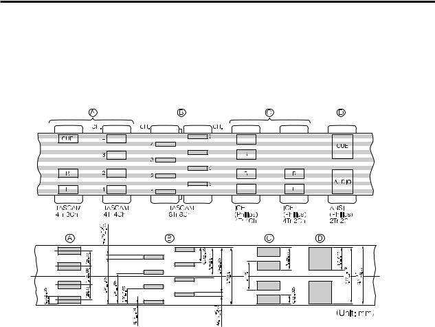
It also employs a discrete 4-channel format head developed especially by TEAC for TASCAM multitrack cassette recorders. Here is a comparison of various cassette formats:
Playing back standard (stereo) prerecorded tapes: Tapes recorded on stereo cassette recorders can play back properly on the 424 MKIII if you set the track playback, tape speed, and noise reduction type correctly. Tracks 1 and 2 roughly follow the standard "stereo" format, but tracks 3 and 4 use the "Side B" (reverse side) tracks. So you must turn off Track 3-4 playback to avoid hearing the flip side playing backwards. If the cassette was recorded with Dolby B type noise reduction, the DBX NR switch should be set to OFF.
For the same reasons, tapes recorded on the Portastudio 424 MKIII will not play back properly on stereo cassette recorders. Material recorded on the 424 MKIII must be mixed down to stereo for final distribution.
The 424 MKIII needs the entire width of the tape to record its four tracks, eliminating the option of recording on both sides (actually, it's both directions). Therefore, you should decide which
side (side "A" or side "B") you want to use and use that side exclusively. It's a good idea to get into habit of consistently using the same side on all multitrack tapes.
Tape Type
The Portastudio 424 MKIII is internally adjusted for HIGH BIAS Type II tape. This means that for best results, you should only use tapes of this type. TDK SA, Maxell XL-II or equivalent formulations are recommended. We strongly suggest that you select one good quality brand and use it exclusively. The time you spend creating your multitrack master is much more valuable than the money you save by buying inferior tape. The cassette shell essentially becomes a part of the 424 MKIII's transport. Poor quality shells can cause wrinkles, snarls and shredding of the edges of the tape with use. Even small scratches on the tape oxide can cause "dropouts" (temporary loss of signal) on one or more tracks. High quality tapes are less likely to cause problems in the long run.
9

Accidental Erase/Record Protection
To protect a finished master tape, it is necessary to punch out both record protect tabs. Even though you are recording in only one direction, the 424 MKIII uses the entire width of the tape, as mentioned above. If, for example, you remove only one of the tabs, you could accidentally insert the cassette into the 424 MKIII backwards and erase all four tracks of the master.
|
Side A |
Side B |
safety tab |
|
|
safety tab |
|
Tape Length
Use the shortest possible tape for a given work. It is not unusual to play a tape 100 times before you are finished, so select a cassette length that is as close as possible to the length of the program you plan to record. Cassettes C-60 length and shorter are often made from thicker stock than longer cassettes.
The tape used in C-120 cassettes is extremely thin and can cause winding problems, crimping, wrinkling, and other damage to the oxide coating of the tape which will destroy your work. Don't use C-120s in the 424 MKIII.
Remember that at 2X normal speed, and the "one-side-only" 4-track single direction format means that you have only one quarter of the normal play time:
|
|
(approx.) |
|
Tape Speed |
9.5 cm/sec. |
4.8 cm/sec. |
|
Cassette |
|||
|
|
||
C-46 |
11.5 min. |
23 min. |
|
C-60 |
15 min. |
30 min. |
|
C-90 |
22.5 min. |
45 min. |
10

PORTASTUDIO 424 MKIII Brief Guide |
For detailed information on each feature, see "Features |
and Controls", pp. 39-45 of the supplied manual. |
|
|
|
Input Selection and Adjustment
Ch.1-4
MIC/LINE INPUTS: These are the input jacks for
the mixer channels. Primarily, the 3-contact,
XLR-type connectors are for connection to balanced microphones, and the 1/4" jacks are for line-level, unbalanced signal sources (such as electronic instruments). But you can also connect lower-level signals (down to –50 dBV) to these 1/4" jacks and use the TRIM control to amplify them.
NOTE
DO NOT use both the XLR and 1/4" jacks in the same channel at one time.
Disconnect one when the other is used.
 TRIM : Sets how much preamplification will be
added to the MIC/LINE IN jack. Turn to the
right if the signal needs amplification, to the
left if the signal is so loud it is distorting the mixer electronics.
INPUT : Detemines where the channel signal
comes from.
MIC/LINE (left) brings the mic/line input
into the channel.
OFF (center) shuts off the channel.
TAPE (right) makes tape play back the channel source.
EQ HIGH : Cuts or boosts treble frequencies.
Shelving point is at 10 kHz.
EQ MID sweep : The upper control sets the frequency range, centered from 250 Hz to
5 kHz. The lower control cuts or boosts this frequency range.
EQ LOW : Cuts or boosts bass frequencies.
Shelving point is at 100 Hz.
EFFECT 1 and 2 : These control how much signal will go to the corresponding EFFECT send jacks. They get their signal from a point just after the channel fader.
TAPE CUE : The EFFECT 2 controls can be switched to act as the TAPE CUE level controls (by means of the correspondingly labeled switch) and adjust the playback level for the musicians in the studio.
PAN : Sets the pan position (left-right balance) of the channel. Note that the Left Mix can be recorded on tracks 1 and 3, and the Right
Mix onto tracks 2 and 4.
Channel fader : Sets the volume of the channel feeding the MASTER fader.
Ch.5-6
1/4” STEREO INPUTS : Primarily used for connecting line-level sources. However, you can also connect lower-level signals (down to –50 dBV) to these 1/4” jacks and use the TRIM level to amplify them.
TRIM: Sets how much preamplification will be added to the MIC/LINE IN jack. Turn to the right if the signal needs amplification, to the left if the signal is so loud it is causing distortion in the mixer electronics.
INPUT: Determines the source of the channel
signals.
MIC/LINE 1/3/5 (channel 5): Allows you
to choose whether the signal
handled by channel 5 comes from either of the MIC/LINE inputs of
channel 1, either of the MIC/LINE
inputs of channel 3, or the MIC/LINE
input of channel 5.
MIC/LINE 2/4/6 (channel 6): Allows you to choose whether the signal handled by channel 6 comes from either of the MIC/LINE inputs of channel 2, either of the MIC/LINE inputs of channel 4, or the MIC/LINE input of channel 6.
EQ HIGH: Cuts or boosts treble frequencies.
Shelving point is at 10 kHz.
EQ MID (sweep): The upper control sets the frequency range, centered from 250 Hz to 5 kHz. The lower control cuts or boosts this frequency range.
EQ LOW: Cuts or boosts bass frequencies.
Shelving point is at 100 Hz.
EFFECT 1 and 2: These control how much signal will go to the corresponding EFFECT SEND jacks. They get their signal from a point just after the channel fader.
TAPE CUE: The EFFECT 2 controls can be switched to act as the TAPE CUE level controls (by means of the correspondingly labeled switch) and adjust the playback level for the musicians in the studio.
PAN: Sets the pan position (left-right balance) of the channel. Note that the
Left Mix can be recorded on tracks 1 and 3, and the Right Mix onto tracks 2 and 4.
Channel fader: Sets the volume of the channel feeding the MASTER fader.
Ch 7-8
STEREO INPUT: Connect any stereo line-level signal (such an effect return or electronic instrument) here. Alternatively, you can connect two mono line-level signals.
MONO feature: If only one mono signal is to be connected,
connect it to the L jack, and leave the R jack unconnected.
The signal is automatically taken to both the 7 and 8 channels.
LEVEL: Controls the volume of both of the inputs simultaneously. The signal is sent to the destination selected by the
ASSIGN switch.
ASSIGN: This sends the signal(s) at
the STEREO INPUT to the stereo mix for recording (L-R) or to the monitor mix (MON), or turns the signals OFF (center).
Monitor Section
LINE OUT switch: Controls whether the LINE OUT stereo mix will be output to the monitor mix, in stereo (L-R), in mono (MONO) or not at all (OFF).
EFFECT/CUE switch: Controls whether the signals sent to
EFFECT 1 or EFFECT 2/CUE or neither (OFF) will be output to the monitor mix, or you may select neither of these for monitoring (OFF).
LEVEL: Controls the level of the monitor mix feeding the MONITOR OUT jacks and headphones.
Master Section
EFFECT 2/TAPE CUE switch: This alters the function of the four level controls immediately above the pan controls of channels 1 through 4.
MASTER fader: This sets the total output level of the stereo mix.
11 |
12 |

PORTASTUDIO 424 MKIII Brief Guide
Recorder Controls
REHEARSAL : Lets you program a punch-in/out sequence to be used for rehearsals and for AUTO IN/OUT.
AUTO PUNCH : Executes the punch-in recording actually on tape as you practiced in REHEARSAL.
CLEAR : Disables the REHEARSAL and AUTO
IN/OUT functions.
MEMO IN : Hold this key down and press LOC 1 or 2 to load the current counter location into the MEMO 1 or 2 register.
LOC 1 and 2 : When used together with MEMO IN, these keys let you load the current counter location into memory. If only LOC 1 or 2 is hit, the tape will be located to the MEMO 1 or 2 point. Pressing LOC for half a second or more allows you to check the memo point on the display.
RECORD FUNCTION 1-4 : These control which track(s) will be recorded when the master RECORD and the PLAY key is pressed, and choose where the signal to be recorded is coming from.
œSetting to DIRECT routes the channel signal directly to the tape (channel 1 is recorded on track 1, channel 2 on track 2, and so on). Recording level is adjusted by the channel fader only.
œWhen recording the stereo mix: As the labels indicate, tracks 1 and 3 are recorded with the mix in BUSS L, and tracks 2 and 4 are recorded with the mix in BUSS R.
TAPE SPEED : HIGH is 3-3/4 ips (9.5 cm/sec.), double the standard (NORMAL) cassette tape speed of 1-7/8 ips (4.8 cm/sec.).
Meters : The meters numbered 1-4 show the playback or the record level of the respective tape tracks. The average record level should be in the center (0), but occasional peaks up to +6 scale are acceptable.
The MONITOR meters show the level of mixes selected by the MONITOR switches.
Tape counter : A four-digit display that shows the distance the tape has moved from a zero reference point.
REC indicators : They blink to show the corresponding tracks are in record ready, and glow solid when recording starts.
COUNTER RESET : Press to change the counter to "0000".
PITCH CONTROL : Increases or decreases the speed of the transport in play and also in Record, over a 12% range (approx.).
RTZ (Return To Zero) : Lets the tape fast wind to the counter zero point. The tape will automatically start playing from the zero point if PLAY is pressed after RTZ.
REPEAT : Lets the tape play over and over between two memo points.
Transport keys : Principally these work the same as on any cassette recorder.
Rear Panel Connections
EFFECT 2 SEND/TAPE CUE OUT: The signal available at this jack comes from either post channel fader for connection to an additional effects device, or from the tape for connection to a studio speaker system, as selected by means of the EFFECT 2/TAPE
CUE switch.
EFFECT 1 SEND: For sending post-fader signals to effects devices. The returns may be plugged into the stereo inputs.
SUB INPUT L and R: Provide a direct route to the MASTER fader. You may connect an outboard mixer here. The SUB IN R jack is also used to record sync tones on track 4.
REMOTE PUNCH IN/OUT: Connect an optional RC-30P footswitch to this jack.
POWER switch: Push in to turn on the
424 MKIII, and push again to turn it off.
POWER connector: Connect the power cable of the PS-424MKIII power supply to this connector. Never use any power supply with the 424 MKIII except the PS-424MKIII power supply which is appropriate for your area’s voltage.
On the front
PHONES (not shown) : This carries the same mix as the MONITOR OUTPUT jacks, as selected by the MONITOR switches.
TAPE OUTPUTS: These jacks receive signals directly from tape tracks 1–4 and are connected to the inputs of an external mixer, or of another multitrack recorder for making a backup copy of your 4-track master, as required.
DBX NR switch: Normally, leave this switch in the ON position. When you use track 4 for recording and playing back MIDI sync tones or timecode, set to SYNC, to set the dbx NR on for tracks 1 through 3, and off for track 4.
LINE OUTPUT L and R: Normally, connect these jacks to the left and right inputs of your mixdown deck.
MONITOR OUTPUT L and R: These are connected to an amplifier powering the control room speakers.
13 |
14 |
Step-By-Step-Operations Guide
Let’s try the 424 MKIII mixer
Input connections
Powering on
Headphone connection
Routing inputs
To learn how the mixer works, first you need to plug a signal source into one of the 1-8 jacks located at upper top of the unit, in your easy reach.
As an example, we'll use a microphone as the source.
Notes to be read prior to making connections
■Although both XLR-type and 1/4" phone jacks are provided for connection to each of channels 1-4, don't use both jacks on the same channel at the same time.
■Turn all the TRIM and other level controls all the way to the left.
■Turn the EQ controls to their center "flat" position; bring all the faders down; and set all the switches to OFF.
1.Have to hand a dynamic microphone and a set of stereo headphones.
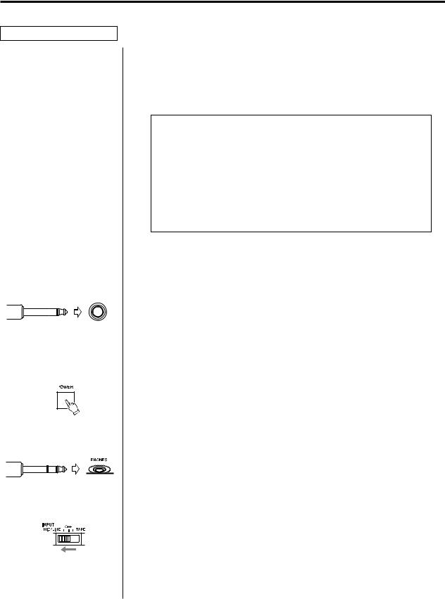
2.Plug the 1/4" plug on your microphone cable into the leftmost MIC/LINE IN jack for channel 1.
3.Turn the 424 MKIII on. The TASCAM logo appears in the display. (The POWER switch is located on the back, beside the power cable.)
4.Plug your headphones into the front PHONES jack, so you can hear the input signal going to the mixer section of the 424 MKIII.
5.Set the channel 1 INPUT select switch to the left (MIC/LINE) position.
15

Panning |
6. Turn the channel 1 PAN control all the way to the left. |
|
|
|
|
|
|
|
7. |
Raise the channel fader to "7" on the scale. |
Channel level |
||||||||
Master level |
8. |
Raise the MASTER fader to "7". |
||||||
Monitor selection |
9. |
Set the MONITOR SELECT LINE OUT switch to the left (L-R) |
||||||
|
|
|
|
|
|
|
|
position. |
|
|
|
|
|
|
|
|
|
|
|
|
|
|
|
|
|
|
TRIM adjustment |
|
10. While speaking into the microphone, turn the TRIM control in |
|||
|
|
|
|
|
channel 1 to the right/MIC until the monitor level meter reads |
|
|
|
|
|
around "0" in average. |
|
|
|
|
|
|
|
|
|
|
|
|
|
|
|
|
|
|
Listening level
11.Slowly turn the MONITOR LEVEL control to the right. You will hear your voice in the left side of the headphones.
When using a line level source (such as electronic instruments) instead of the mic, the TRIM does not need to be turned up very far, if at all.
How to record on track 1
As a trial, let's record your voice on tape.
|
1. |
Have in hand a new cassette tape (Type II, C-90 length or shorter). |
Loading a cassette |
2. |
Open the cassette door using the tab on the right of the door. |
|
|
Insert the cassette tape, and close the cassette door. |
Getting past the leader |
3. |
Press PLAY and allow the tape to run for about 5 seconds. This |
tape |
|
will run the tape leader onto the takeup reel, and put the |
|
|
beginning of the tape in front of the heads. |
16

Resetting the counter |
4. Press the COUNTER RESET switch, so you can use the RTZ |
|
(Return-To-Zero) function to get back to this point. |
Selecting tracks |
5. Set the RECORD FUNCTION switch for TRK 1 to its BUSS L |
||
|
|
|
position. The REC "1" indicator will start blinking in the display |
|
|
|
window, indicating track 1 is in Record Ready mode. |
|
|
|
|
|
|
|
|
|
|
|
|
|
|
|
|
|
|
|
|
|
|
|
|
Mic level adjustment |
6. Speak into the mic. You will see meter 1 move. If no level or too |
||
|
|
|
low a level is shown, continue to speak into the mic and slowly |
|
|
|
turn the channel 1 TRIM control to the right/MIC until the meter |
|
|
|
peaks at no more than "+6". |
|
|
|
|
|
|
|
|
|
|
|
|
|
|
|
|
|
|
|
|
|
|
|
|
|
|
|
|
Beginning to record |
|
7. Hold RECORD and press PLAY to initiate recording. The REC "1" |
||
|
|
|
|
indicator that was blinking in the meter will turn on solid, |
|
|
|
|
indicating track 1 is in Record mode. |
|
|
|
|
|
|
|
|
|
|
|
|
|
|
|
|
|
|
|
|
|
8. |
Speak into the mic. |
Stopping recording |
9. |
Press STOP to stop the tape and finish recording. |
Putting track into "Safe" 10. The REC "1" indicator in the meter should now be blinking as before. Set the RECORD FUNCTION switch for TRK1 to its SAFE position.
17
 Loading...