


TASCAM
TEAC Professional Division
488
5700123804

Table Of Contents
Safety Instructions |
|
3 |
Introduction |
|
4 |
The Recording System |
|
5-6 |
The three steps to multitrack |
6 |
|
Understanding the Mixer |
7-8 |
|
Signal flow in the 488 mixer |
7 |
|
Cue monitor system |
|
7 |
Multitrack Cassette Recorder |
9 |
|
Track Format and Tape Recommendations |
9-10 |
|
Block Diagram |
|
11 |
Brief Guide |
|
12-15 |
Step-By-Step Operations Guide |
16-24 |
|
Let's tray the 488 mixer |
16 |
|
How to record on track 1 |
18 |
|
How to make an overdub on track 2 |
20 |
|
How to record all other tracks |
20 |
|
How to record many sources |
22 |
|
onto a single track |
||
How to record multiple tracks |
22 |
|
simultaneously |
|
|
How to mix down |
|
23 |
Using Memory Location Points |
25-26 |
|
Loading MEMO points |
25 |
|
Locating the tape |
|
26 |
Repeat Play |
|
27 |
PUNCH-IN or INSERT Recording |
28-30 |
|
REHEARSE function |
|
28 |
Punch-in/out procedure |
28 |
|
Punch-in/out with RECORD |
29 |
|
Using RECORD FUNCTION switch |
30 |
|
Using the remote footswitch (RC-30P) |
30 |
|
Bouncing Tracks |
(Ping-Pong) |
31-32 |
Ping-pong procedure |
|
31 |
Ping-pong in stereo procedure |
32 |
|
Using Effects with the PORTASTUDIO 488 |
33-34 |
|
Setting effect send levels |
33 |
|
Setting the output level of effect devices |
33 |
|
Setting the mix/balance control |
33 |
|
on effect devices |
|
|
How to connect your effects devices |
34 |
|
Recording with TAPE SYNC |
35 |
|
Features and Controls |
|
36-43 |
488 Mixer |
|
36 |
Input section |
|
|
Tape monitor section |
37 |
|
Channel controls |
|
37 |
Channel assignment section • |
37 |
|
Effect send section |
|
38 |
Stereo input section |
38 |
|
Group master section |
40 |
|
Monitor section |
|
40 |
488 Recorder |
|
41 |
Cassette loading and dbx system |
||
Transport-controls |
|
41 |
Track controls |
|
42 |
Displays |
locators |
42 |
Auto |
3 |
|
Sync features |
|
43 |
Care and Maintenance |
|
44-45 |
Cleaning |
|
44 |
Degaussing (demagnetizing) |
45 |
|
How the dbx Works |
|
45 |
Troubleshooting |
|
46 |
Specifications |
|
46-48 |
Level Diagrams |
|
49-50 |
Optional Accessories |
|
51 |
Safety Instructions
CAUTION:
•Read all of these instructions.
•Save these instructions for later use.
•Follow all warnings and instructions marked on the audio equipment.
1.Read Instructions — Allthesafetyandoperatinginstructions should beread before the appliance is operated.
2.Retain Instructions — The safety and operating instructions should be retained for future reference.
3.Heed Warnings — All warnings on the appliance and in the operating instructions should be adhered to.
4.Follow Instructions — All operating and use instructions should be followed.
5.Water and Moisture — The appliance should not be used near water — for example, near a bathtub, washbowl, kitchen sink, laundry tub, in a wet basement, or near a swimming pool, etc.
6.Carts and Stands — The appliance should be used only with a cart or stand that is recommended by the manufacturer.
6A. An appliance and cart combination should be moved with care. Quick stops, excessive force, and uneven surfaces may cause the appliance and cart combination to overturn.
7.Wall or Ceiling Mounting - The appliance should be mount¬ ed to a wall or ceiling only as recommended by the manu¬ facturer.
8.Ventilation — The appliance should be situated so that its location or position does not interfere with its proper venti¬ lation. For example, the appliance should not be situated on a bed, sofa, rug, or similar surface that may block the ventilation openings; or, placed in a built-in installation, such as a bookcase or cabinet that may impede the flow of air through the ventilation openings.
9.Heat — The appliance should be situated away from heat sources such as radiators, heat registers, stoves, or other appliances (including amplifiers) that produce heat.
10.Power Sources — The appliance should be connected to a power supply only of the type described in the operating in¬ structions or as marked on the appliance.
11.Grounding or Polarization — The precautions that should be taken so that the grounding or polarization means of an appliance is not defeated.
12.Power-Cord Protection — Power-supply cords should be routed so that they are not likely to be walked on or pinch¬ ed by items placed upon or against them, paying particular attention to cords at plugs, convenience receptacles, and the point where they exit from the appliance.
13.Cleaning — The appliance should be cleaned only as recom¬ mended by the manufacturer.
14.Power Lines — An outdoor antenna should be located away from power lines.
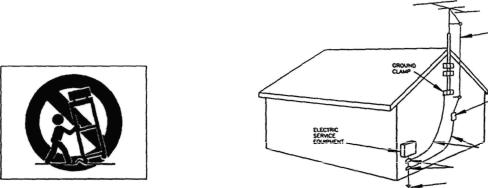
15.Outdoor Antenna Grounding — If an outside antenna is connected to the receiver, be sure the antenna system is grounded so as to provide some protection against voltage surges and built up static charges. Section 810 of the National Electrical Code, ANSI/NFPA No. 70 - 1984, pro¬ vides information with respect to proper grounding of the mast and supporting structure, grounding of the lead-in wire to an antenna discharge unit, size of grounding con¬ ductors, location of antenna-discharge unit, connection to grounding electrodes, and requirements for the grounding electrode. See Figure below.
EXAMPLE OF ANTENNA GROUNDING
AS PER NATIONAL
ELECTRICAL CODE
(DISCHARGE UNIT
(NEC SECTION 810-20)
GROUNDING CONDUCTORS (NEC SECTION 610-21)
GROUND CLAMPS
POWER SERVICE GROUNDING ELECTRODE SYSTEM
(NEC ART 250. PART H)
NEC - NATIONAL ELECTRICAL CODE
16.Nonuse Periods — The power cord of the appliance should be unplugged from the outlet when left unused for a long period of time.
17.Object and Liquid Entry — Care should be taken so that objects do not fall and liquids are not spilled into the en¬ closure through openings.
18.Damage Requiring Service - The appliance should be ser¬ viced by qualified service personnel when:
A.The power-supply cord or the plug has been damaged; or
B.Objects have fallen, or liquid has been spilled into the appliance; or
C.The appliance has been exposed to rain; or
D.The appliance does not appear to operate normally or exhibits a marked change in performance; or
E.The appliance has been dropped, or the enclosure dam¬ aged.
19.Servicing — The user should not attempt to service the appliance beyond that described in the operating instruc¬ tions. All other servicing should be referred to qualified service personnel.
3

Introduction
ThePORTASTUDIO 488is...
The PORTASTUDIO 488 is an 8-track "Multitrack Master" cassettetape recorderand afull-function mixer with 12 inputs/4 outputs combined into a singleworkstation.
Its high audio quality and creative flexibility reflect the experience and innovation that have allowed TASCAM to earn its reputation in professional audio production fields, and its user-friendly design makes the 488 suitable for anyone, fromexpertto novice.
NOTE FOR U.K. CUSTOMERS
U.K. CustomersOnly:
Due to the variety of plugs being used in the U.K.; this unitis soldwithoutan AC plug. Please request your dealer to install the correct plug to match the mains power outlet where your unit will be usedaspertheseinstructions.
IMPORTANT
Thewiresinthismainsleadcoloredin in
accordance with the following code:
BLUE: NEUTRAL
BROWN: LIVE
Asthecoloursofthewiresinthemainslead of this apparatus may not correspond with the coloured markings identifying the terminalsofyourplug, proceedasfollows:
The wire Which is coloured BLUE must be connected to the terminal which is marked with the letter N or coloured BLACK. The wire which is coloured BROWN must be connected to the terminal which is marked withtheletterLorcoloured RED.
This product is manufactured to comply with the radio interference of EEC directive "82/499/EEC."
Using this manual : To getthe most out of your 488, please take the time to read through this manual. Some time spent now will keep you fromoverlooking some ofthe featuresthatmake the 488 a more creative tool. You may discover somenewtricksyouhaven'ttriedbefore.
Use of capital letters : In general, we use all uppercasetype to designate a particularswitch, control, jack name or label (like PAN). Transport modes and some features are described with an uppercasefirstletter(like Record mode).
THIS DIGITAL APPARATUS DOES NOT EXCEED THE CLASS B LIMITS FOR RADIO NOISE EMISSIONS FROM DIGITAL APPARATUS AS SET OUT IN THE RADIO INTERFERENCE REGULATIONS OF THE CANADIAN DEPARTMENT OF COMMUNICATIONS.
4
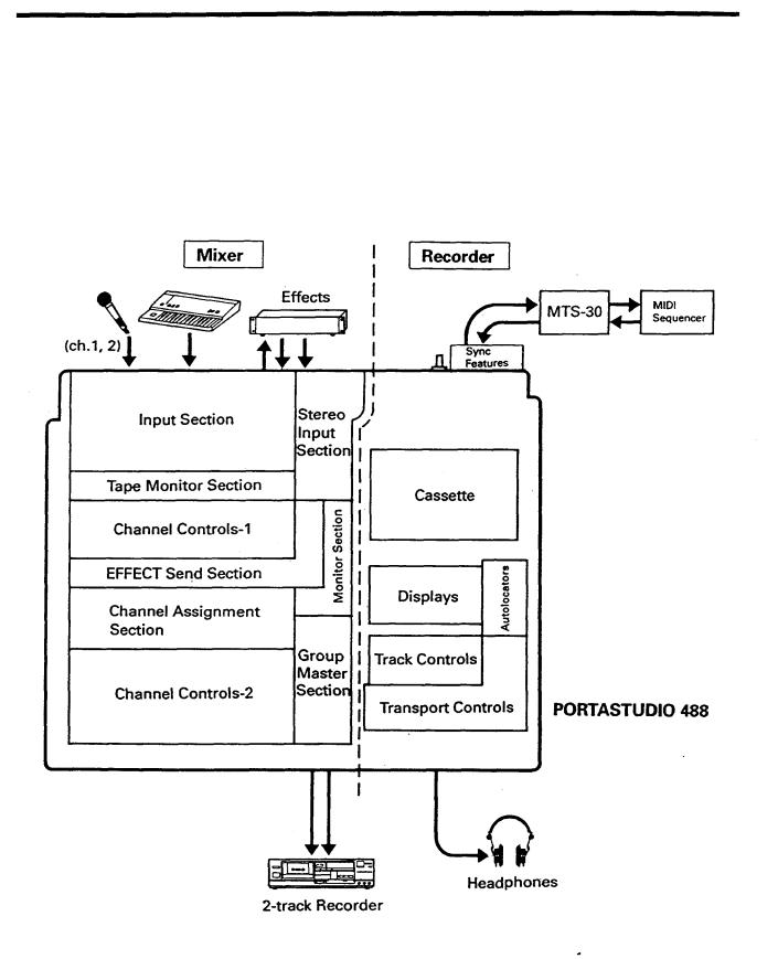
The Recording System
The PORTASTUDIO 488 is a complete audio production facility in a single box. It is divided intotwo majorsections: afull-function mixerand an 8-channel, multitrack cassette recorder. To complete the recording system, you'll
additionally need these: Input devices (microphones, instruments). Output devices (headphones), 2-track recorder, Effects processors,etc.
5
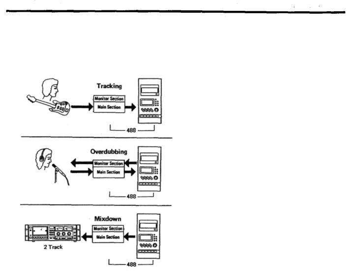
The Three Stepsto Multitrack
The diagram below depicts how signals from equipmentconnectedtothe488can berouted.
InTRACKING and Overdubbing, the mixerinputs are usually microphones or instruments, going IC. different tracks of the recorder. In OVERDUBBING, theMONITOR section andTAPE CUE of the mixer must be used to listen to previous tracks while you record newones, so there is a two-way flowthrough the console. In MIXDOWN, signal comes from the multitrack and issentto an external 2-trackrecorder.
6
Understanding the Mixer
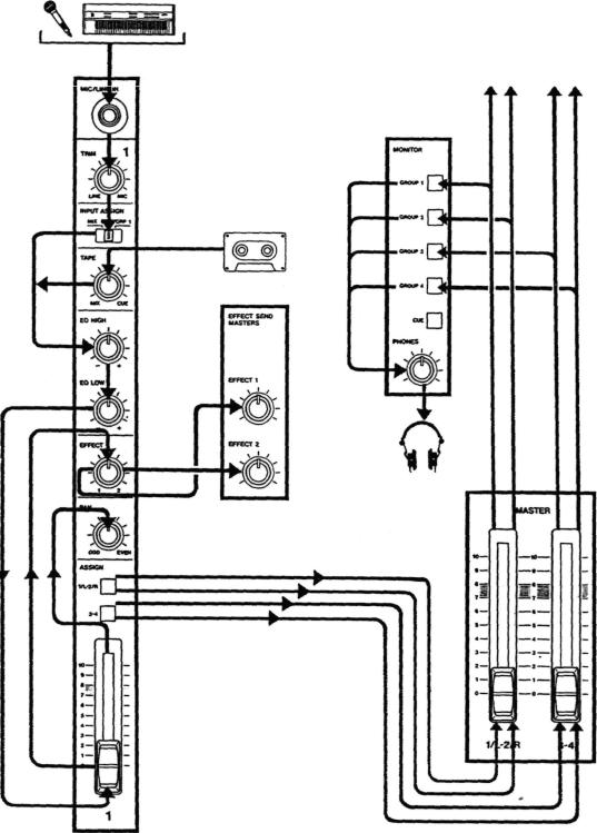
Signal Flowinthe488mixer
The illustration below shows how the input signal passes through the 488 Mixer section. After the MASTER faders they go to the GROUP
OUT jacks and the multitrack recorder (not shown). This is the most important signal route inthe mixerand iscalled "Main Mix".
ToTape
(RECORD FUNCTION switches)
CueMonitorSystem
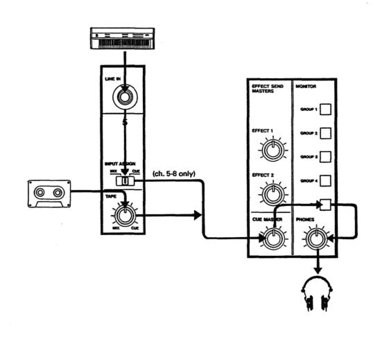
The CUE mix and MONITOR switches are also crucial for successful multitrack recording, because they control what you hear in the
headphones. ThisCUE mixistotallyindependent fromtheMainMixgoingtotape. If you don't use the CUE mix, you run the risk of accidentally "bouncing tracks" every time you record new material.
The TAPE control in each ofthe first8 channels gets its signal from the multitrack recorder, and sends playback to either the Main Mix, or the CUE Monitor. When all of these TAPE controls areturnedtothe right(CUE), and CUE ispressed in the MONITOR switch, you can hear tape playback in the headphones. You can adjustthe monitor level ofeach trackby adjusting itsTAPE control. The channels of the Main Mix remain freeto handle external inputsforrecording.
The five MONITOR Source switches choose which mix(es) you can hear in the PHONES - the CUE mix, andanyofthefourGROUPS. Youpress the applicable GROUP switch to hear what you are recording: for example, GROUP 4 while recording ontoTrack4.
If you need to add external sources to the CUE mix (for example, a MIDI-synchronized drum machine that you don'twantto record on tape), the INPUT ASSIGN switches for channels 5 to 8 havea CUE position. Thissendsthe LINE INjack signal directly to the CUE mix. (In this case, the LINE IN signal is disconnected from the mixer channel controls, so there must be a volume control onthe source device.)
8

Multitrack Cassette Recorder
The 488 records on readily available standard (Philips) Compact Cassette tape, high bias Type II. The recorder has 8 tracks whilethe mixer has 4 group outs; you can record a maximum of 4 tracks atonetime. Formore details, see "Howto Record Multiple Tracks Simultaneously", page 22.
The 488's dbx Noise Reduction virtually eliminates unwanted tape noise. A special SYNC feature turns off the dbx on track 8 separately, making it possible to record and play back the MIDI sync tones or SMPTE/EBU time code without being affected by the dbx encode/decode. This ensures that the sync tones/code are recorded andplayedbackwithout unnecessary processing. With proper operating techniques, it is not necessary to leave a guard band between music and sync tone tracks because of the low crosstalk of the TASCAM heads.
The transport controls of the 488 are microprocessor operated, allowing highly
reliable functions that make the unit easier to use:
•A three position autolocator (MEMO 1 and 2 and Zero) allows key positions to be located automatically.
•REPEAT allows a section to be played over and over between the MEM01 and MEM02 pointsforrehearsal.
•RHSL (rehearsal) allows you to "preview" whatyourrecordingwillsound likeandrepeat the record punch in/out sequence as many times as you wish before actually executing it ontape.
•Thetapespeedcan beincreasedordecreased with the PITCH CONTROL dial in both playback and record, to match pitch or for specialeffects.
•Punch-in and Punch-outcan be engaged using the optional RC-30P footswitch, which gives you an "extra hand" inthe recording process.
Track Format and Tape Recommendations
The Portastudio 488 uses a basic speed of 9.5 cm/sec. (3-3/4 ips) which is two times (2X) the normal speed of a standard audio cassette. It also employs a discrete 8-channel format head
developed especially by TEAC for TASCAM multitrack cassette recorders. Here is a comparision ofvariouscassetteformats:
9
Tapes recorded on stereo cassette recorders will not playback properly on the 488 because of the differences in the track format and tape speed. For the same reasons, tapes recorded on the Portastudio 488 will not playback properly on stereo cassette recorders. Material recorded on the 488 must be mixed down to stereo for final distribution.
The 488 needs the entire width of the tape to record its eighttracks, eliminating the option of recording on both sides (actually, it's both directions). Therefore, you should decide which side (side- "A" or side "B") you want to use and use that side exclusively. It's a good idea to get into habit of consistently using the same side on all multitracktapes.
TapeType
The Portastudio 488 is internally adjusted for HIGH BIAS "Type II" tape. For best results, you should only use tapes of this type. TDK SA, Maxell XL-II or equivalent formulations are recommended. We strongly suggest that you select one good quality brand and use it exclusively. The time you spend creating your multitrack master is much more valuable than the money you save by buying inferiortape. The cassette shell essentially becomes a part of the 488's transport. Poor quality shells can cause wrinkles, snarls and shredding of the edges of the tape with use. Even small scratches on the tape oxide can cause "dropouts" (temporary loss of signal) on one or more tracks. High quality tapes are less likely to cause problems in the long run.
Accidental Erase/Record Protection
To protect a finished master tape, it is necessary to punch out both record protect tabs. Even though you are recording in only one direction, the 488 uses the entire width of the tape, as mentioned above. If, for example, you remove only one of the tabs, you could accidentally insert the cassette into the 488 backwards and erase all eighttracks ofthe master.
Tape Length
Use the shortest possible tape for a given work. It is not unusual to play a tape 100 times before you are finished, so select a cassette length that is as close as possible to the length of the program you plan to record. Cassettes C-60 length and shorter are often made from thicker stockthan longercassettes.
The tape used in C-120 cassettes is extremely thin and can cause winding problems, crimping, wrinkling, and otherdamageto the oxide coating of the tape which will destroy your work. Don't use C-120s inthe 488.
Remember that at 2X normal speed, and the "one-side-only" 8-track single direction format meansthatyou have only 1/4X normal playtime:
|
(approx.) |
C-30 |
7.5 min |
|
|
C-46 |
11.5 min |
|
|
C-60 |
15min |
|
|
C-90 |
22.5 min |
|
|
Side A
safety tab
SideB safety tab
10

Sliders and Controls

Brief Guide
Inputselectionandadjustment
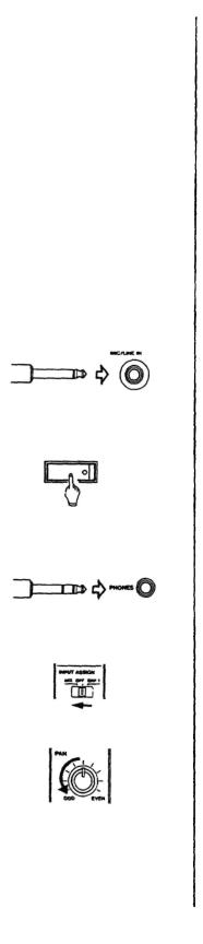
MIC/LINE IN (Ch. 1-2) or LINE IN (Ch. 3-8): These aretheinputjacksforthe mixer channels. Connect line-level signals to any channel; connect lower-level signals (from microphones and some guitar pickups) to the MIC/LINE INs (channel1 or2).
TRIM (Ch. 1-2 only): Sets how much preamplification will be added to the MIC/LINE IN jack. Turn tothe rightifthesignal needsamplification, tothe left ifthe signal isso loud itisdistortingthe mixerelectronics.
•INPUT ASSIGN: DetermineswheretheINjacksignalwillgoto.
MIXsendsitthroughthemixerchannel, andisthenormalsetting.
OFFisusedduringatypicalmixdown.
GRP 1-4. or CUE sends the inputsignal directly to a GROUP or the CUE mix, bypassing the channel controls - this makes the IN jackwork as a "buss input", for use with external mixers or other line inputs that don't need channelcontrol.
•Ifyou are using MIDI-sequenced "virtual tracks", connectthemto channels 5-8, sotheycanbesentdirectlytotheCUE mixwithoutbeingrecorded.
Tape Mix/Cue
This acts as a combination level and assignment control for the correspondingtapetrack.
•Atcenter(12o'clock), thetapesignal isoffandcantbe heard.
•Turn ittothe leftofcenter (MIX) to sendthetape signalthroughthe mixer channel.
-IfINPUTASSIGNisalsoinitsMIXposition, thetapereturnandtheinput signalwill bothgothroughthe mixerchannel simultaneously.
-Turn itall the way to the leftand turn INPUT ASSIGN offto make tape theonlysourceofthechannelatmixdown.
•Turn itto the right ofcenter (CUE) to send thetape signal to the CUE mix for monitoringthrough headphones.
Equalization and Effect send
•EQ HIGH: Cuts or boosts treble frequencies. Its shelving point is 10 kHz; it can affectfrequenciesdownto2 kHz.
EQ LOW: Cuts or boosts bass frequencies. Shelving type, 100 Hz, can affect frequenciesupto500Hz.
•EFFECT: A post-fader effectsend from the channel. The center position is OFF. TurntothelefttosendsignaltoEffectSendMaster1, andtotherighttosend signalto EffectSend Master2.
Channel Output section
-ASSIGN switches: Press to send the outputofthe channel to any (or all) offour output groups for recording onto the multitrack. Works in cooperation with PAN.
•PAN: Sets the pan position (left-rightbalance) ofthe channel between odd/even groups (leftfor 1 &3, rightfor2&4, centerforall).
- Channel fader: Setsthevolume ofthechannelfeedingthegroup masterfaders.
12
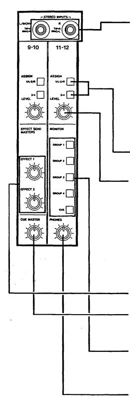
STEREOINPUTS(Channel9-12)
STEREO INPUTS: Connectany line-level signal (such as an effect return, or electronic instrument) here. They can operateinthreedifferentways.
•Four Sources: By using a special 3-conductorTip- Ring-Sleeve (TRS) cable, each jackcan accepttwo signals atonce (Tiptothe left. Ring tothe righton Channel9/10, viceversaonChannel11/12).
•TwoSources: IfTRS "stereosplitter"cablesarenot available, standard mono 1/4" cables can be connectedtothesejacks. Inthiscase,theleft(9/10) jackcan be assigned onlytothe "left" groups (1 & 3), and the right (11/12) jack can only reach the rightgroups(2&4).
•One source: Plug a mono cable intothe left(9/10) jack and leave the right (11/12) jack empty. The signal automatically connects to both channels, makingassignmenttoallfourgroupspossible.
ASSIGN switches: Pressto send the outputofthe Stereo channel to any (or all) of the four output groups for recording ontothe multitrack.
-LEVEL: Controls the volume of the stereo channels feedingtheGROUPMASTERS.
Master Section
-EFFECT SEND MASTERS: These are the master controls forthetwoeffectsend outputs.
-CUE MASTER: This controls the overall level ofthe TAPE CUE mix. (CUE must be pressed in the MONITOR section forthisto have any effecton your headphone mix.)
-MONITOR switches: These select what signals you will hear in the PHONES, and see displayed on the MONITOR L/R meter. You can hear any or all of the four output groups of the mixer, plus the tape cue mix, dependingonwhatispresseddown.
•PHONES: This is the volume control for the built-in headphoneamp.
3

Recorder controls
-METERS: These showthe recorded level of the respective tape tracks. The average level should be in the center (0), but peaks up to +6areacceptable.
• The MONITOR L/R meters showthe level of mixes selected by the MONITOR switches.
COUNTER: A four-digit display that shows the current tape position, used for autolocation functions.
•COUNTER RESET: Press to change the counter to "0000".
RTZ: Return-To-Zero - press to fast wind the transporttothe "0000" position.
REPEAT: Press to set up a continuous playrewind loopbetweenthetwo MEMO points.
LOC 1 and 2: Press to fast wind (LOCate) the transportto either MEMO point.
MEMO: Hold and press LOC 1 orLOC 2toenter thecurrentcounterlocation asa newMEMO point.
RHSL: Rehearsal. In this mode, recording is not possible. Pressingthe punch in pedal, orthe RECORD key, will automatically mute the tape playback of any tracks' in Rec Ready mode.
TRANSPORT KEYS: These workthe same as on anycassette recorder.
RECORD FUNCTION switches 1-8: It is possible to record on up to fourtracks at once. Each Group of the mixer connects to two tracks; for example. Group 1 connects to tracks 1 and 5. You cannot record on track 1 and 5 simultaneously. When a track is in REC READY, its indicator will flash above in the meter panel. In Record mode, the indicator willturnsolid.
PITCH CONTROL: Increases or decreases the speed ofthetransportin both Record orPlay mode, overa12%range.
14

OUTPUT JACKS: Rear panel
EFFECT SENDS 1 and 2: Connect these to the inputs ofeffectdevices.
-GROUP OUTs 1-4: Connect 1/L and 2/R to the inputs of your mixdown deck. The GROUP OUT jacks can also be connected to the inputs of external mixers,etc.
• Note: Since the TAPE CUE section does not come to these jacks, GROUP OUTs are not intended for connection to a monitoring system. Use the PHONES jack for this purpose.
•DBX NR: Thisturnsthe dbxnoise reduction on and offforall eighttracks. Normally, leaveiton.
•SYNC ON/OFF: This disconnects the input and output of track 8 from the mixer, and connects it to the SYNC jacks. For normal recording, leave this off. When using Track 8 to record and play back MIDIsynctonesortimecode,turn iton.
•SYNC IN jack: Connectthe outputofa MIDI sync or SMPTE time code generator to thisjack.
•SYNC OUT jack: Connectthistothe inputof a MIDIsyncorSMPTE timecodereader.
15
Step-By-Step Operations Guide
Let'strythe488 mixer
Beforeconnections
Inputconnections
To learn howthe mixer works, firstyou need to plug a signal source into one ofthe ten 1/4" jacks located at upper top ofthe 488, in your easyreach.
Asanexample, we'lluseamicrophoneasthesource.
•TurnalltheTRIMcontrolsallthewaytotheleft/LINE position.
•TurnalltheotherlevelandEQcontrolstotheircenter"0"position; bring all the faders down; and set all the switches to OFF or to theirUp position.
1.Have in hand a dynamic microphone and a set of stereo headphones.
2.Plug the 1/4" plug on your microphone cable into the leftmost MIC/LINE INJackforchannel1.
Powering on |
3. Turn the 488 on. (The POWER switch is located on the back, |
|
besidethe powercable.) |
Headphone connection |
4. Plug your headphones into the front PHONES jack, so you can |
|
heartheinputsignalgoingtothemixersectionofthe488. |
Routing inputs |
5. Setthe channel 11NPUT ASSIGN switch to the left/MIX position. |
Panning |
6. Turn the channel 1 PAN control all the way to the left/ODD |
|
position. |

Assigning to groups |
7. Pressthechannel1ASSIGN"1/L-2/R"switch. |
Channel level |
8. |
Raisethechannelfaderto"7"onthescale. |
Group level |
9. |
RaisetheMASTER "1/L-2/R"faderto"7". |
Monitor selection |
10. PresstheMONITOR "GROUP 1"switch. |
|
Listening level |
11. TurnthePHONES levelcontroluptothe12o'clockposition. |
TRIMadjustment |
12. While speaking into the mic, slowly turn the TRIM control in |
|
channel 1 to the right. You will hear your voice in the |
|
headphones. |
|
When using a line level source {such as electronic instruments) |
|
instead ofthe mic, the TRIM does not need to beturned up very |
|
far, ifatall. |
17
 Loading...