


OPERATION AND INSTALLATION FUNCIONAMIENTO E INSTALACIÓN MODE D’EMPLOI ET INSTALLATION
DHW heat pump water heater
Calentador de agua con bomba eléctrica de calor Chauffe-eau à thermopompe
»Accelera 220 E
»Accelera 300 E
Conforms to ANSI/UL 499, UL 1995, UL 94-5 VA, UL 174
Certified to CAN/CSA C22.2 No. 110
Conforme a ANSI/UL 499, UL 1995, UL 94-5 VA, UL 174
Certificación con CAN/CSA Std. C22.2 No. 110
Conforme à la norme ANSI/UL Std. 174
Certifié à la norme CAN/CSA Std. C22.2 No. 110
Tested and certified by WQA to NSF/ANSI 372 for lead free compliance.
Probado y certificado por WQA NSF/ANSI 372 para el cumplimiento de las regulaciones sin plomo.
Testé et certifié par WQA à la NSF/ANSI 372 pour une utilisation sans plomb.

CONTENTS
ACCELERA® 220 E QUICK START-UP GUIDE
OPERATION
1.General information _________________________________________7
2.Safety__________________________________________________________7
2.1Intended use ______________________________________________________ 7
2.2Incorrect use______________________________________________________ 7
2.3General safety instructions ____________________________________ 7
2.4ETL designation __________________________________________________ 8
2.5Appliance labels _________________________________________________ 8
3.Appliance description _____________________________________ 10
3.1Heating the DHW tank _________________________________________ 11
3.2Appliance operation outside the application limits______ 11
3.3Frost protection _________________________________________________ 11
4.Settings _____________________________________________________ 11
4.1Display and controls____________________________________________ 11
4.2Settings ___________________________________________________________ 11
4.3Calling up fault codes __________________________________________ 13
4.4Rapid heating key ______________________________________________ 13
4.5Emergency shutdown __________________________________________ 14
5.Maintenance and care _____________________________________ 14
6.Troubleshooting ____________________________________________ 14
6.1Fault codes _______________________________________________________ 15
INSTALLATION
7.Safety________________________________________________________ 16
7.1General safety instructions ___________________________________ 16
7.2Instructions, standards and regulations ___________________ 16
7.3Incorrect use_____________________________________________________ 16
7.4Qualification _____________________________________________________ 16
8.Appliance description _____________________________________ 16
8.1Standard delivery _______________________________________________ 16
8.2Required accessories __________________________________________ 16
8.3Further accessories_____________________________________________ 16
9.Preparations ________________________________________________ 16
9.1Transport _________________________________________________________ 16
9.2Storage____________________________________________________________ 17
9.3Installation site__________________________________________________ 17
9.4Siting the appliance ____________________________________________ 18
9.5Minimum clearances ___________________________________________ 18
10.Installation __________________________________________________ 19
10.1Water connection _______________________________________________ 19
10.2Condensate drain _______________________________________________ 19
10.3Power supply ____________________________________________________ 20
10.4Assembling the appliance ____________________________________ 21
11.Commissioning _____________________________________________ 21
11.1Commissioning __________________________________________________ 21
11.2Recommissioning _______________________________________________ 21
12.Shutting down______________________________________________ 22
13.Troubleshooting ____________________________________________ 22
13.1Fault table ________________________________________________________ 22
13.2Resetting the safety pressure limiter _______________________ 22
13.3Resetting the high limit safety cut-out _____________________ 22
13.4Motor overload relay___________________________________________ 22
14.Maintenance and cleaning ________________________________ 23
14.1Removing the appliance cover _______________________________ 23
14.2Removing the casing ring_____________________________________ 23
14.3Cleaning the evaporator_______________________________________ 24
14.4Draining the tank _______________________________________________ 24
14.5Descaling the electric booster element ____________________ 24
14.6Protective anode ________________________________________________ 24
14.7Valves _____________________________________________________________ 24
14.8Replacing the power cable ___________________________________ 24
14.9Fitting the casing ring _________________________________________ 24
14.10Fitting the appliance cover ___________________________________ 25
15.Specification ________________________________________________ 26
15.1Dimensions and connections _________________________________ 26
15.2Wiring diagram _________________________________________________ 28
15.3Data table ________________________________________________________ 29
16.Limited Warranty___________________________________________ 30
2 | Accelera® 220-300 E |
www.stiebel-eltron-usa.com |
SPECIAL INFORMATION
This manual includes important information regarding the safe and efficient handling of the water heater. Keep this manual with the water heater at all times.
Work must only be carried out by a licensed installer who has read and understands these instructions. All federal, state and local codes must be followed. Failure to do so may result in equipment failure, serious injury, or death.
While working on the water heater, disconnect the power supply.
Illustrations in these instructions are designed to aid a general understanding and may deviate from the actual water heater version. No claims can be derived from such installations.
Limited liability:
We have collated all details and information in this manual in due consideration of applicable standards and regulations, the state of the art and our long-term know-how and experience.
Losses due to the following are excluded from our liability:
-Non-observance of these instructions
-Incorrect use
-Installation of water heater by unqualified personnel
-Unauthorized modifications
-Use of unauthorized spare parts
For more information on liability, see the warranty section at the back of this manual.
Copyright:
These operating and installation instructions are subject to copyright.
Transferring these instructions to third parties, copying of any kind, either in total or extracts therefrom, as well as their use and/or conveying its contents are prohibited without our written consent.
Violations are liable to claims for compensation. Further claims are reserved.
We hold the copyright:
Stiebel Eltron, Inc.
17 West Street | West Hatfield, MA 01088 Tel. 413-247-3380 | Fax 413-247-3369 Email info@stiebel-eltron-usa.com www.stiebel-eltron-usa.com
Should you have any questions regarding the installation or operation of the water heater, please contact our customer service. Tel. (USA) 800-582-8423 or 413-247-3380
Please record your serial number and information:
Serial No.:
Date of purchase:
Register your product |
|
||
|
|
|
ENGLISH |
|
NOTE: |
|
|
|
|
|
|
|
You must register this product within 90 days |
|
|
|
of purchase on our web site in order to acti- |
|
|
|
vate any standard warranty or to be eligible for |
|
|
|
the extended warranty. Go to our website at: |
|
|
|
www.stiebel-eltron-usa.com and click on “Register Your |
|
|
|
Product.” |
|
|
|
|
|
|
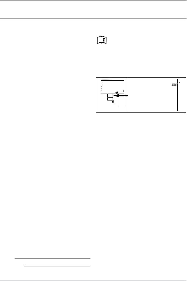
Before beginning the registration process, we suggest that you gather the necessary information as follows:
|
1 |
00000-0000-000000 |
D0000035352 |
1Serial number on the type plate
Type, Example: Accelera 220 E (the type plate can be found on the appliance above the “DHW outlet” connection). Number listed after “Nr.”
Place of Purchase Purchase Date First & Last Name Email address Physical Address Phone Number
If you have any questions concerning the registration process or warranty options, please contact Stiebel Eltron USA directly at (800)-582-8423.
www.stiebel-eltron-usa.com |
Accelera® 220-300 E | 3 |

QUICK START-UP GUIDE
General information
ACCELERA® 220 E QUICK START-UP GUIDE
Overview:
Installation of this water heater is similar to standard electric water heaters, with a few minor exceptions. Be sure to follow all state and local codes during installation. This Quick Start-up Guide is not intended to be a substitute for the complete installation manual. Be sure to follow all safety precautions.
Unpacking:
DO NOT unpack the water heater until it is located at the point of installation. Follow all instructions in the manual and be sure to use caution, as this unit is top heavy. After unpacking, DO NOT lay the unit down and DO NOT jar or tip the unit past 45 degrees on a hand truck. If the appliance has not been completely vertical during transport or setup, it must rest in a vertical position for at least one hour before commissioning.
Installation of water connections:
1.Find a suitable location that fits the room spacing guidelines on the next page. The minimum volume of the room is 10´ x 10´ x 10´. Be sure vents are parallel to the wall with the fan facing the most open area along that wall. Please note: a drain pan is recommended, and may be code in some areas.
2.The inlet & outlet plumbing connections on the unit are 1˝ male NPT. It is recommended to use union connections for easier serviceability. Install a boiler drain at the cold water inlet for easier draining of the tank.
3.The temperature & pressure (T&P) safety valve port is ¾˝ female NPT. A T&P valve is supplied which is rated to release water at 100 psi and/or 210°F. Plumb this connection to a bucket or directly to a drain. If it is plumbed to a bucket, check it often for any accumulated water.
For hook-up, follow all state and local codes for check valves, expansion tanks, shut off valves, gauges, etc. Install a 70 psi pressure reduction valve if the water pressure exceeds 70 psi (See 10.1, “Water connection”, pg. 19)
Condensate drain:
Run the condensate drain connection directly into a drain or use a condensate pump to drain into a suitable location (See 10.2, “Condensate drain”, pg. 19).
Fill & flush tank:
Run water and be sure the tank is full prior to turning on the electricity.
Installation/electrical:
Use a 240 Volt / 15 Amp double pole breaker and connect to the water heater L1,L2 & ground (See 10.3, “Power supply”, pg. 20).
4 | Accelera® 220-300 E |
www.stiebel-eltron-usa.com |

QUICK START-UP GUIDE
Required room dimensions and clearances
› Do not install in a room |
|
|
with less than 800 cubic |
Minimum room volume: |
14˝ |
feet of total volume. |
800 ft2, 10´ x 10´ x 8´ |
|
› Do not install with the air |
(22.7 m2, 3 m x 3 m x 2.4 m) |
(0.4 m) |
exhaust pointing at a wall |
|
Air flow |
or any surface closer than |
Air flow |
intake |
6 feet away. |
|
|
exhaust |
|
|
|
|
› Do not install with the air |
6´ (1.8 m) |
2´ (0.6 m) |
||
|
intake pointing to a wall or |
|||
|
|
|
|
|
|
any surface closer than 2 |
|
An object |
|
|
feet away. |
|
|
|
› If you are installing the |
|
next to the |
|
|
|
unit must |
|
||
|
water heater next to |
|
|
|
|
≤42˝ |
be less than |
|
|
|
another appliance, it |
|
||
|
cannot be taller than 42 |
(1.1 m) |
42˝ high |
|
|
inches. Otherwise, it will |
|
|
|
|
obstruct air flow to and |
|
|
|
|
from the unit. |
|
|
|
› |
Failure to follow |
Acceptable positioning, vent parallel to a wall: |
||
|
installation instructions |
|
|
8˝ (0.2 m) |
|
will void the factory |
|
|
|
|
warranty. |
|
|
|
|
|
6´ (1.8 m) |
2´ (0.6 m) |
|
|
|
|
Air flow |
Air flow |
|
|
|
exhaust |
|
|
|
|
intake |
|
|
|
|
|
|
Acceptable positioning, vent parallel to a wall in a corner:
8˝ (0.2 m) |
|
|
Air flow |
|
intake |
8˝ |
2´ |
(0.2 m) |
(0.6 m) |
|
|
|
2´ |
|
(0.6 m) |
6´ |
Air flow |
(1.8 m) |
exhaust |
ENGLISH
www.stiebel-eltron-usa.com |
Accelera 220-300 E | 5 |
QUICK START-UP GUIDE |
|
|
|
|
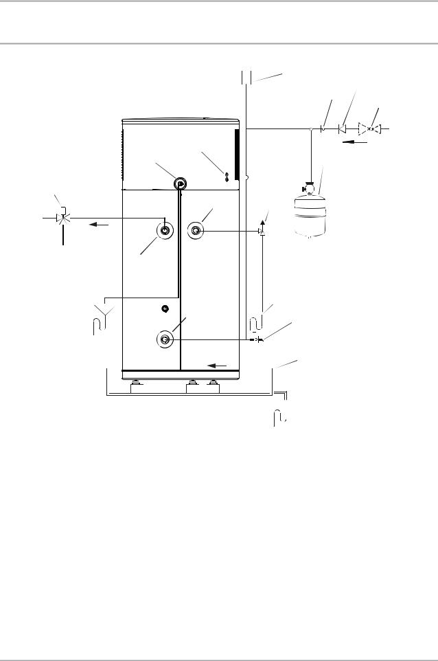
Plumbing connections |
|
|
|
|
|
|
1 |
|
8 |
|
|
|
7 |
|
|
|
|
9 |
|
|
|
|
|
|
|
14 |
6 |
|
Cold water |
|
11 |
|
||
|
|
|
||
3 |
|
5 |
|
|
|
4 |
|
|
|
C |
H |
|
|
|
|
M |
|
|
|
|
Hot water |
|
|
|
|
2 |
|
|
|
|
10 |
12 |
|
|
|
|
13 |
|
|
1Vacuum breaker
2Hot water connection (1˝ NPT)
3 Mixing valve (optional, supplied by installer)
4Connection for T&P valve ¾˝ NPT
5 T&P valve ¾˝ NPT, 0.69 MPa @ 99°C (100 psi @ 210°F) (supplied with unit)
6Expansion tank (required, supplied by installer)
7 Straight-through shut-off valve (supplied by installer)
8Check valve (required, supplied by installer)
9 0.48 MPa (70 psi) pressure reduction valve (optional, supplied by installer)
10Cold water connection (1˝ NPT)
11Condensate drain (elbow supplied with unit)
12Drain valve (supplied by installer)
13Drain pan (supplied by installer)
14Condensate spillover
6 | Accelera 220-300 E |
www.stiebel-eltron-usa.com |

OPERATION
General information
OPERATION
1.General information
The chapters “Special information” and “Operation” are intended for appliance users and qualified contractors.
The chapter “Installation” is intended for qualified contractors.
Note
Read these instructions carefully before using the appliance and retain them for future reference.
Pass on the instructions to a new user if required.
2.Safety
This chapter provides an overview of all important actions required for a safe and trouble-free operation.
2.1Intended use
WARNING Electrocution
Contact with live components presents a threat to life. Damage to the electric insulation or to individual components may result in a threat to life.
If there is damage to the insulation, disconnect the power supply and arrange a repair.
All work on the electrical installation must be carried out by a qualified contractor.
WARNING Scalding
The water in the DHW tank can be heated to temperatures in excess of 149°F/65°C. There is a risk of scalding at outlet temperatures in excess of 110°F/43°C.
Ensure you do not come into contact with the water when discharged.
WARNING Burns
Touching hot components can lead to burns.
When working on hot components, always wear protective working clothing and safety gloves.
The pipework connected to the DHW outlet of the appliance can reach temperatures in excess of 149°F/65°C.
The appliance is intended for DHW heating within the application |
|
|
WARNING Scalding |
|
|
The appliance is filled with refrigerant at the factory. |
|
limits (See 15.3, “Data table”, pg. 29). |
|
|
|
|
|
||
|
|
In case of leaking refrigerant, avoid coming into contact |
|
The appliance is intended for domestic use, i.e. it can be used |
|
|
|
|
|
with the refrigerant or inhaling the released vapors. Ven- |
|
safely by untrained persons. The appliance can also be used in a |
|
|
tilate the rooms affected. |
non-domestic environment, e.g. in a small business, as long as it |
|
|
|
|
|
|
|
is used in the same way. |
! |
CAUTION Injury |
|
|
|||
Any other use beyond that described shall be deemed inappropri- |
Never place any objects on top of the appliance. If objects |
||
ate. Observation of these instructions and of instructions for any |
|
|
are left on the appliance, noise emissions may increase |
accessories used is also part of the correct use of this appliance. |
|
|
due to resulting vibrations, and the objects could fall |
|
|
|
and cause injury. |
|
|
|
|
2.2Incorrect use
The following are not permitted: |
! |
CAUTION |
|
- Heating liquids other than potable water |
To reduce the risk of excessive pressures and tempera- |
||
|
tures in this water heater, install temperature and pres- |
||
- Operating the appliance with an empty DHW tank |
|
||
|
sure protective equipment required by local codes and |
||
- Operating the appliance outside the application limits (See |
|
||
|
no less than a combination temperature and pressure |
||
15.3, “Data table”, pg. 29) |
|
relief valve certified by a nationally recognized testing |
|
- Interrupting the power supply, as without power supply the |
|
laboratory that maintains periodic inspection of produc- |
|
appliance is not protected against corrosion |
|
tion of listed equipment or materials, as meeting the re- |
|
|
|
|
quirements for Relief Valves and Automatic Gas Shutoff |
2.3 |
General safety instructions |
|
Devices for Hot Water Supply Systems, ANSI Z21.22. This |
Only qualified contractors should carry out the electrical work and |
|
valve must be marked with a maximum set pressure not |
|
|
to exceed the marked maximum working pressure of the |
||
installation of this appliance. Qualified contractors are responsible |
|
water heater. Install the valve into an opening provided |
|
for adherence to all applicable regulations. |
|
and marked for this purpose in the water heater, and |
|
Operate the appliance only when fully installed and with all safety |
|
orient it or provide tubing so that any discharge from |
|
|
the valve exits only within 6 inches above, or at any |
||
equipment fitted. |
|
||
|
distance below, the structural floor, and does not contact |
||
|
|
|
|
|
WARNING Injury |
|
any live electrical part. The discharge opening must not |
! |
|
be blocked or reduced in size under any circumstances. |
|
The appliance may be used by children aged 8 and up and |
|
||
|
|
||
persons with reduced physical, sensory or mental capabilities or a lack of experience and know-how, provided that they are supervised or they have been instructed on how to use the appliance safely and have understood the resulting risks. Children must never play with the appliance. Children must never clean the appliance or perform user maintenance unless they are supervised.
ENGLISH
www.stiebel-eltron-usa.com |
Accelera® 220-300 E | 7 |
OPERATION
Safety
! |
CAUTION |
Hydrogen gas is produced by this heater in a hot water |
|
|
system that has not been used for a long period of time |
|
(2 weeks or more). Hydrogen gas is extremely flamma- |
|
ble. To reduce the risk of injury under these conditions, |
|
it is recommended that the hot water faucet be opened |
|
for several minutes at the kitchen sink before using any |
|
electrical appliance connected to the hot water system. |
|
When hydrogen is present, there will probably be an |
|
unusual sound such as air escaping through the pipe as |
|
the water begins to flow. There should be no smoking or |
|
open flame near the faucet at the time it is open. |
|
|
! |
Material losses |
If you disconnect the appliance from the power supply, it |
|
|
is no longer protected against frost. |
|
Do not interrupt the power supply to the appliance. |
|
|
|
|
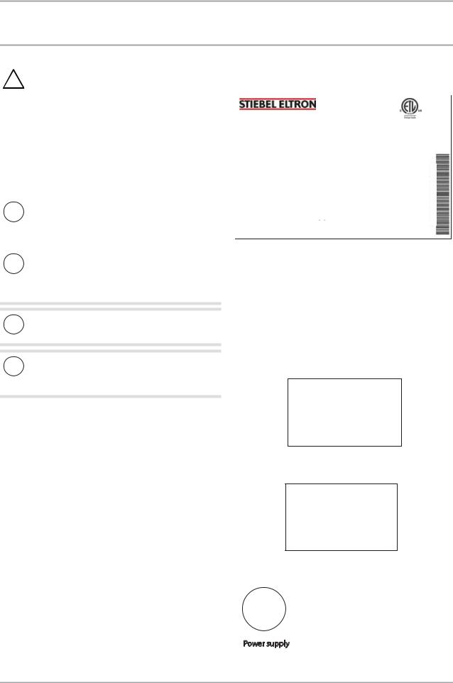
2.5Appliance labels
1. Type plate label for the Accelera 220 E
No.:#### / ######
Part number/code article: |
233058 |
Electrical/électrique |
|
Voltage/tension: |
Single phase 220-240 V |
Frequency/fréquence: |
50 / 60 Hz |
Breaker/disjoncteur: |
15 A |
Pnmax (rated power input)/puissance nominale: |
2200 W |
Maximum allowable ratings/courant nominal: |
2200 W, 9.17 A |
Protection class/indicie de protection: |
IP 24 |
Heat pump/pompe à chaleur: |
|
PN (Air 107.6°F / Water 149°F): |
0.54 kW |
Refrigerant/frigorigène: |
R-134a |
Refrigerant charge/frigorigène poids de remplissage: |
1.874 lb / 850g |
Max. operating pressure/max. pression de service: |
348.1 PSI / 2,400 kPa |
Lock rotor current/puissance blockade: |
15.3 A |
MCA: |
14 A |
Rated compressor load/courant nominale du compresseur: |
2.5 A |
Motor fan/moteur de ventilateur: |
24 W |
DHW cylinder/DHW cylindre: |
|
Backup heating element/chauffage d'appoint: |
1690 W |
Max. operating pressure/max. pression de service: |
87 PSI / 600 kPa |
Max. operating temperature/max. temperature de service: |
168.8°F / 76°C |
Tank material/matériau réservoir: |
Steel |
Nominal capacity/capacité nominale: |
58.12 gal / 220 l |
Tank test pressure/contrôle de réservoir: |
130.5 pSI / 900 kPa |
285872-34892
Read the instructions carefully. |
XXXX - XXXXXX |
|
Tested for leaks. |
- |
|
XXXXXX |
|
|
Lira attentivement la notice. |
|
|
Étanchéité testé. |
|
|
Made in EU/Fabriqué en UE |
|
|
Material losses
!Never cover this appliance. Covering the air intake or air discharge leads to a reduced air supply. If the air supply is restricted, the operational reliability of the appliance cannot be guaranteed.
Material losses
!Only operate the appliance when the DHW tank has been filled.
Material losses
!Keep the appliance installation room free from air contaminated with oil or salt and corrosive or explosive substances.
2.4ETL designation
The ETL designation shows that the appliance meets all essential UL and CAN/CSA requirements. This appliance conforms to:
-UL Standard 1995
-UL Standard 174
-CAN/CSA Standard C22.2 No.236-05
-CAN/CSA Standard C22.2 No.110-94
2. Condensate drain information label
Condensate |
|
|
Condenso |
38055- |
|
Condensat |
||
- |
||
|
3118015683 |
|
|
|
3. Hot water outlet location label
Hot Water Outlet
Salida de agua caliente
Sortie eau chaude
311803-38055
4. Cold water outlet location label
Cold Water Inlet
Entrada para agua fría
Entrée eau froide
311802-38055
5. Power connection information label
|
!Attention! |
|
Must connect to |
Power supply |
240 V, 15 A |
Disconect power supply |
Double-pole |
Before opening the cover |
Circuit breaker |
8 | Accelera® 220-300 E |
www.stiebel-eltron-usa.com |

OPERATION
Safety
6. Scald risk information label


 AQUA CALIENTE
 ABRASAR


 52
52 125
125 
Une température de l'eau de plus de 52°C (125°F) peut causer des brûlures graves ou la mort par ébouillantage
Les enfants, les personnes handicapées et les personnes âgées courent le plus grand risque de brûlures.
Lire la notice d'emploi avant d'ajuster la température du chauffe-eau.
Vérifier la température de l'eau avant de prendre un bain ou une douche.
Des dispositifs de limitation de température sont disponibles. Voir la notice d'emploi.
ATTENTION
L'eau chaude peut provoquer des brûlures de 3ème degré:
En 6 secondes à 60°C (140°F). En 30 secondes à 54°C (130°F). Réglé à l'usine à 52°C (125°F).
Contacter le personnel de service après-vente qualifié pour toute modification.
Agua con temperatura de más de 52 °C (125 °F) puede al instante causar quemaduras graves o la muerte por escaldadura.
Niños, personas con discapacidades o mayores se encuentran en mayor peligro de escaldadura.
Mire las instrucciones de uso antes de ajustar la temperatura en el calentador de agua.
Pruebe el agua antes de bañarse o de ducharse.
Están disponibles válvulas para regular la temperatura. Mire las instrucciones de uso.
ADVERTENCIA
Agua muy caliente puede causar quemaduras de 3er grado. En 6 segundos A 60 °C (140 °F). En 30 segundos A 54 °C (130 °F).
La regulación fue ajustada en la producción
A 52 °C (125°F). Si necesita ajustar la regulación, contácte al técnico de servicio calificado.
7. Gasket connection information label
For reason of corrosion protection use flat gasket ring. Never seal threadshemp (equipment Damage!).
38055-311804 |
Para la protección contra la corrosión use |
sellos planos de los tubos. Una unión |
con cáñamo no está permitida (riesgo de daño del equipo!).
Pour des raisons de protection contre la corrosion, le raccordement est à réaliser par joints plats. L'étanchéïfication au chanvre n'est pas autorisée (dommages au matériel!).
8. Pressure & temperature relief valve information label
Relief valve
P lum ber:
The relief valve installation m ust be fitted to this socket. The pressure and tem perature relief valve has to m eet local codes and com ply with A NS I Z21 .22 .
Soupape de sûreté
Plombier:
L'installation de la soupape de sûreté doit être branchée sur cette prise. La soupape de sûreté pour la pression et la température doit être conforme à la réglementation locale et à ANSI Z21.22.
Válvula de seguridad
Plomero:
La válvula de seguridad debe instalarse en esta conexión.
Las válvulas limitadoras de presión y temperatura tienen que 38055 ajustarse al código local y cumplir con la norma ANSI Z21.22. -315321
9. Kyoto protocol information label
ES: Sistema herméticamente cerrado que contiene gases de efecto invernadero mencionados en el protocolo de Kioto. BG: Съдържа посочените в Протокола от Киото флуорирани парникови газове - херметически затворена система.
299581-36960
10. Supplemental heat element information label
If the water heater is retrofitted with a supplemental heat element make sure that both thermostat are adjusted on the same
water temperature set point.
Si le chauffe-eau est rénové avec un élément de chauffe supplémentaire, assurez-vous que les deux thermostats soient ajustés
à la même température de réglage de l'eau.
Si el calentador de agua está adaptado a un elemento calentador 38055 suplementario, asegúrese que ambos termostatos estén ajustados
a la misma temperatura de agua.
-315322
ENGLISH
www.stiebel-eltron-usa.com |
Accelera® 220-300 E | 9 |

OPERATION
Appliance description
11. Booster heater element information label
CAUTION :
for use only in water
ATTENTION:
pour l'utilisation dans l'eau
ATENCIÓN:
se usa sólo para en agua
315683-38055
12. Appliance must be vertical for at least one hour before commissioning information label
WARNING / WARNUNG
The unit must remain in vertical position for at least one hour before putting unit into operation.
Die Anlage muss min. 1 Stunde lang vor deren
Inbetriebnahme in senkrechter Position bleiben.
L’appareil doit être placé en position verticale au moins une heure avant sa mise en route.
La unidad tiene que quedar en la posición vertical al menos durante una hora antes de poner la unidad en funcionamiento.
315125-38055
3.Appliance description
The appliance is designed for indoor installation. The appliance recirculates ambient air and does not require outdoor air. The appliance extracts heat from the ambient air. This heat is utilized to heat the water in the DHW tank with added electric power. The amount of electric energy and time required to heat-up the DHW depends on the temperature and humidity of the ambient air.
This heat extraction results in a drop in the ambient temperature inside the installation room by between 2°F/1°C and 5.5°F/3°C. The appliance also extracts moisture from the air, which turns into condensate. The condensate is drained from the appliance via the condensate drain.
When a hot water draw-off point is opened, the hot DHW is pushed out of the appliance by the in-flow of cold DHW.
To protect against corrosion, the inside of the DHW tank is coated with special enamel and is additionally equipped with an impressed current anode.
The electronic control unit makes energy saving adjustments easier. Subject to the power supply and usage pattern, the water is heated up automatically to the set temperature.
Heat pump operating principle
A hermetic circuit within the appliance contains refrigerant (See 15.3, “Data table”, pg. 29). This refrigerant evaporates at low temperatures and collects heat from the ambient air.
In the evaporator, the refrigerant changes from its liquid into its gaseous state. A compressor draws in the gaseous refrigerant and compresses it. This increase in pressure raises the refrigerant temperature.
The compression process requires electrical energy. The energy (motor heat) is not lost, but is discharged to the downstream condenser. The cooled refrigerant passes a filter dryer. There, the refrigerant indirectly transfers heat to the DHW tank and the liquid refrigerant is routed to a two-flood evaporator. An expansion valve then reduces the still prevalent pressure and the cycle starts again.
Note
In the event of an interruption of the power supply, the compressor is blocked from operating for at least one minute. The electronic control board (ECB) delays electronic starting for one minute while the appliance goes through its initializing process.
If the compressor subsequently fails to start, it may be blocked by additional safety devices (Klixon and high pressure switch). If the compressor is switched off due to the Klixon, the pressure difference between the high and low pressure sides of the refrigerant circuit may be the cause. When the pressure difference is equalized (approximately 5 minutes), the compressor turns on. If a tripped high pressure switch caused the blocking of the compressor, this may be due to a failed thermostat or high ambient air temperature. After the power supply has been re-established, the appliance continues to operate with the parameters that were selected before the power supply was interrupted.
10 | Accelera® 220-300 E |
www.stiebel-eltron-usa.com |
OPERATION
Settings
3.1Heating the DHW tank
The water is heated by the heat pump through the condenser wrapped around the tank. This is the appliance’s standard mode of operation.
An integral sensor in the tank is connected to an electronic device to measure the thermal energy content of the water in the DHW tank. The water in the DHW tank is heated if its temperature is lower than the set temperature.
For information on the heat-up time of the water in the DHW tank, See 15.3, “Data table”, pg. 29.
3.1.1 Electric booster element
The electric booster element is automatically activated in case of a damaged heat pump or to provide more hot water than the current tank supply.
In the event of an unexpectedly high hot water demand, the booster heater can be manually activated. See 4.4.1, “Comfort heating”, pg. 13.
In the event of an appliance fault, a backup mode can be set to activate the electric booster element. See 4.4.2, “Emergency back up mode”, pg. 13.
3.2Appliance operation outside the application limits
3.2.1 Ambient temperatures below the application limit
If hoar frost is growing on the evaporator fins, the hoar frost temperature monitor switches the heat pump compressor off. The compressor switches on automatically once the evaporator defrosts.
To guarantee fault-free operation of the appliance, make sure you operate the appliance within its application limits (See 15.3, “Data table”, pg. 29).
Note
Heat-up times are longer while the evaporator is defrosting.
3.2.2 Ambient temperatures above the application limit
The safety equipment switches the appliance off if the upper application limit is exceeded.
Following a cooling time of several minutes, the appliance is switched back on automatically. The appliance is switched off again if the ambient temperature rises above the permissible temperature value again.
To guarantee fault-free operation of the appliance, make sure you operate the appliance within its application limits (See 15.3, “Data table”, pg. 29).
3.3Frost protection
The appliance activates a frost protection function if the integral sensor in the DHW tank detects a temperature below 50°F/10°C. The appliance then heats the water in parallel mode by using both the heat pump and the electric booster element. The heat pump and electric booster element switch off once the temperature detected by the integral sensor is more than 65°F/18°C.
www.stiebel-eltron-usa.com
4.Settings
4.1 |
Display and controls |
ENGLISH |
|
||
|
|
|
|
Note |
|
|
|
|
|
The back-light of the display will illuminate for 15 seconds |
|
|
|
|
|
after pressing any button. |
|
|
|
|
12 |
1 |
|
|
|
e l c t r o n i c c |
2 |
11
3
10


 9
9


8

4
7 |
|
|
0006_ |
|
|
|
|||
|
|
|||
5 |
03 13 |
|||
6 |
||||
|
|
26_ |
||
1 Set temperature symbol
2Amount of amount of mixed water display (l @ 40°C /gal @ 104°F)
Actual temperature display, upper tank section / Set temperature1display
Set temperature2display Fault code display
3 Plus key
4 Minus key
5 Service/error symbol
6 Electric booster element symbol
7 Heat pump symbol
8 Rapid heating key
9 Set temperature 2 symbol
10 Menu key
11 Amount of mixed water symbol
12 Actual temperature symbol
The "electric booster element" and "heat pump" symbols are displayed when these appliance components are active. The display of these symbols does not necessarily mean that the electric booster element and the heat pump are running.
Service/fault symbol
Note
Notify your contractor if the service/fault symbol appears on the display. Continuous illumination of the symbol indicates that the fault is not preventing appliance operation.
A flashing service/fault symbol indicates that the water is not being heated and that it is essential you notify your contractor.
4.2Settings
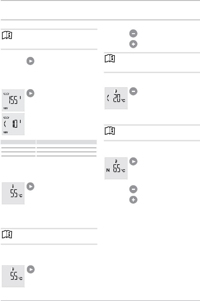
In standard display mode, the display shows the current amount of mixed water.
Accelera® 220-300 E | 11
OPERATION
Settings
Note
15 seconds after every adjustment, the appliance automatically switches back to the standard display and saves the set value.
With the menu key, all information and setting options are called up in sequence. The relevant symbol appears with each setting.
4.2.1 Amount of mixed water display (standard display)
DHW demand for
Bath
Shower
Hand washing
The currently available amount of mixed water at 104°F/40°C when mixed with 59°F/15°C cold water is shown.
If there is no usable hot water in the tank, the display shows < 10 l.
Amount of mixed water at 104°F/40°C)
32-40 gal (120-150 l)
9-13 gal (30-50 l)
½-1½ gal (2-5 l)
The amount of mixed water that can be achieved depends on the set point temperature.
4.2.2 Actual temperature display
In the mixed water menu, press the menu key once to get to the actual temperature menu.
The current actual temperature in the upper section of the DHW tank is
shown. This largely corresponds to the outlet temperature.
4.2.3 Set temperature 1
Note
For reasons of legionella prevention, never set the DHW temperature lower than 124°F/50°C).
The set temperature 1 is the DHW temperature to which the appliance regulates if no external signal transmitter is connected and active. Set temperature 1 is set to 131°F/55°C at the factory.
In the actual temperature menu, press the menu key once to get to the menu for set temperature 1.
The set temperature 1 symbol appears.
Adjust set temperature 1 from 69 to 149°F / 20.5 to 65°C using the plus and minus keys.
Note
Another way to adjust set temperature 1 is to press the plus or minus key when in standard display (amount of mixed water).
Frost protection
If the set temperature is set to less than 69°F/20.5°C, only frost protection remains active. The water heater will not run.
4.2.4 Set temperature 2
Note
For reasons of legionella prevention, never set the DHW temperature lower than 124°F/50°C).
Set temperature 2 is the DHW temperature to which the appliance regulates if an external signal transmitter is connected and active.
In the set temperature 1 menu, press the menu key once to get to the menu for set temperature 2.
The set temperature 2 symbol appears. The display of set temperature 2 is denoted with an "N".
Adjust set temperature 2 from 69 to 149°F / 20.5 to 65°C) using the plus and minus keys.
Operation with external signal transmitter (240 V input)
The connection of the heat pump to an external signal offers the possibility of heating water to a raised temperature set point during periods when electric rates are favorable, for example during times when PV power is available or low tariff utility rates are in effect.
The external signal may be offered by a PV system or low tariff transmission of a utility.
This set temperature 2 is activated when a phase (LF signal) is present at terminal X0/LF (See 10.3.1, “Connection with external signal transmitter”, pg. 20). While activated, set temperature 2 replaces the standard set DHW temperature ("set temperature 1").
If set temperature 2 has been activated by the external signal transmitter, this set temperature will then be active for at least 20 minutes. If the signal remains active after those 20 minutes passed, the compressor will run until the LF signal ends. If not, the selected set temperature 1 is activated again.
12 | Accelera® 220-300 E |
www.stiebel-eltron-usa.com |

OPERATION
Settings
If the relevant set DHW temperature is accomplished, the compressor switches off and remains off for a minimum idle time of 20 minutes.
The following diagram illustrates the connections by means of a sample signal sequence of an external signal transmitter.
Example: |
|
|
|
|
|
|
|
|
|
|
|
|
|
|
|
|
|
|
- DHW temperature = 131°F/55°C) |
|
|
|
|
|
|
|
|
|
|||||||||
- Set temperature 1 = 124°F/50°C) |
|
|
|
|
|
|
|
|
|
|||||||||
- Set temperature 2 = 149°F/65°C) |
|
|
|
|
|
|
|
|
|
|||||||||
A |
|
|
|
|
|
|
|
|
|
|
|
|
|
|
|
|
|
|
1 |
|
|
|
|
|
|
|
|
|
|
|
|
|
|
|
|
|
|
0 |
|
|
|
|
|
|
|
|
|
|
|
|
|
|
|
|
|
|
0 |
5 |
10 |
15 |
20 |
25 |
30 |
35 |
40 |
45 |
50 |
55 |
60 |
65 |
70 |
75 |
t [min] |
|
|
B |
|
|
|
|
|
|
|
|
|
|
|
|
|
|
|
|
|
D0000034613 |
1 |
|
|
|
|
|
|
|
|
|
|
|
|
|
|
|
|
|
|
|
|
|
|
|
|
|
|
|
|
|
|
|
|
|
|
|
1 |
|
0 |
|
|
|
|
|
|
|
|
|
|
|
|
|
|
|
|
2 |
|
0 |
5 |
10 |
15 |
20 |
25 |
30 |
35 |
40 |
45 |
50 |
55 |
60 |
65 |
70 |
75 |
t [min] |
|
|
|
|
|||||||||||||||||
A LF signal
B Compressor
1 20 min. minimum runtime, set temperature 2
2 20 min. minimum compressor idle time
Note
An LF signal must be active for at least 60 seconds before the control unit responds to it. This prevents cycling of the compressor due to fast changing sun radiation condition.
4.3Calling up fault codes
Based on the set temperature 2 menu, press the menu key once to get to the fault code menu. A fault code will appear if a fault has occurred. If no error has occurred, this menu is not available.
See 6.1, “Fault codes”, pg. 15.
4.4Rapid heating key
Press the rapid heating key.
The heat pump and electric booster element symbols appear.
4.4.1 Comfort heating
Normally, the rapid heating key is used to activate the comfort heating function, which enables the water heater to satisfy an unexpectedly high DHW demand without changing any of the appliance's standard settings.
When comfort heating is activated by pressing the rapid heating key, the heat pump and the electric booster element will start in parallel, irrespective of the selected set temperature. To save energy, the electric booster element switches off as soon as a temperature of 149°F/65°C has been achieved in the upper tank section (rapid heating).
The heat pump remains on and the comfort heating function remains active until a temperature of 149°F/65°C) has been achieved in the entire DHW tank (comfort heating). The appliance then automatically switches back to the previously set parameters.
Note
The electric booster element and heat pump symbols are displayed until the comfort heating function has terminated.
During comfort heating, the electric booster element symbol is displayed until the heat pump has heated the entire tank to 149°F/65°C and the function is terminated, even though the electric booster element switches off when the 149°F/65°C) has been achieved in the upper tank section.
Note
If comfort heating has been activated, it can be canceled by reducing the set temperature.
Hold down the minus key, until you hear a clicking noise caused by the heat pump and booster heater switching off. The set temperature will jump back to the value that was selected before comfort heating was activated.
4.4.2 Emergency back up mode
If the heat pump is out of order, it is possible to use the electric booster element in back up mode to ensure hot water production. The electric supply to the compressor shuts down if the water temperature increase is less than 0.5°F/0.25°C) in a time frame of 13 hours. In this case the fault code is activated and will flash. The fault key flashes on the display and a fault code indicates that the appliance is not heating the water.
To activate the backup mode, press the rapid heating key. After the rapid heating key has been pressed, the indicated fault code increases by a value of 256, as the fault codes are summed together (See 6.1, “Fault codes”, pg. 15). The fault key continues to flash. The electric booster element is activated.
The current set temperature (set temperature 1 or set temperature 2) is ignored. In emergency mode, the appliance operates with a fixed set temperature of 104°F/40°C). After a one-off activation of the function via the rapid heating key, this function remains active for 7 days.
Following 7 days of backup operation, the electric booster element is deactivated. The fault code shown on the display decreases by 256.
If the rapid heating key is pressed again within the 7 days of backup operation, the 7-day run time for emergency mode will start afresh from that point.
Pressing the rapid heating key only activates backup mode if a fault with fault code 8 occurred previously. In standard mode pressing the rapid heating key only triggers a one-off heating of the DHW tank for a single instance.
An interruption of the power supply will disable the back up mode immediately. The heat pump will try to heat again for a duration of 13 hours after the power outage. After 13 hours without a water temperature increase, the flashing service key occurs again and the back up function may be activated.
ENGLISH
www.stiebel-eltron-usa.com |
Accelera® 220-300 E | 13 |

OPERATION Maintenance and care
4.5Emergency shutdown
In the event of an emergency, carry out the following steps:
Interrupt the power supply by unplugging the appliance or by shutting off the circuit breaker.
Shut off the cold water supply.
Immediately notify a qualified contractor, as the appliance is not protected against corrosion while the power supply is interrupted.
Drain the water out of the tank if there is a power outage longer than 2 days.
5.Maintenance and care
WARNING Electrocution
Do not insert objects through the grille into the interior of the appliance.
Never spray the appliance with water. Never spray water into the appliance.
WARNING Injury
! Maintenance work, such as checking the electrical safety, must only be carried out by a qualified contractor.
Appliance components
Casing
Air intake grille / air discharge grille
DHW tank
Electric booster element
Appliance
Condensate drain
Care and maintenance tips
Use a damp cloth to clean the casing sections. Never use abrasive or corrosive cleaning agents.
Clean the air intake grille and air discharge grille every six months. Cobwebs or other kinds of contamination can restrict the air supply to the appliance.
The DHW tank is equipped with a maintenance-free impressed current anode to safeguard against corrosion. The power supply must not be interrupted while the appliance is filled with water to enable the impressed current anode to provide protection. Otherwise there is a risk of corrosion.
Have the electric booster element descaled from time to time. This will extend the expected life of the electric booster element.
Have the safety assembly and the evaporator checked regularly by a qualified contractor.
Undo the condensate drain. Check that the condensate drain is clear and remove any dirt from the condensate drain connection of the appliance.
6.Troubleshooting
Problem |
Cause |
|
Remedy |
No hot water is |
No power to the appli- |
|
Check that the appliance |
available. |
ance. |
|
is connected to the power |
|
|
|
supply. |
|
The circuit breaker in the |
|
Check whether the circuit |
electric panel has tripped. breaker in the electrical panel has tripped. If required, disconnect the appliance from the power supply and replace the circuit breaker. Contact your contractor if the circuit breaker blows again after the appliance is connected to the power supply.
Problem |
Cause |
|
Remedy |
||
No hot water is |
The air intake or air dis- |
Check the air intake grille |
|||
available. |
charge of the appliance is |
and air discharge grille for |
|||
|
|
|
blocked. |
contamination. Remove any |
|
|
|
|
|
contamination (See 14, “Main- |
|
|
|
|
|
tenance and cleaning”, pg. |
|
|
|
|
|
23). |
|
|
|
|
|
|
|
|
|
|
The ambient temperature |
Wait for the appliance to cool |
|
|
|
|
exceeds the upper ap- |
down. Call a qualified con- |
|
|
|
|
plication limit (See 15.3, |
tractor if the appliance does |
|
|
|
|
“Data table”, pg. 29). |
not switch back on automat- |
|
|
|
|
The appliance safety |
ically. |
|
|
|
|
equipment has responded |
|
|
|
|
|
and the appliance has |
|
|
|
|
|
switched off automati- |
|
|
|
|
|
cally. |
|
|
|
|
|
The ambient temperature |
Wait until the appliance |
|
|
|
|
falls below the lower ap- |
switches back on automati- |
|
|
|
|
plication limit (See 15.3, |
cally. |
|
|
|
|
“Data table”, pg. 29). |
|
|
|
|
|
The evaporator is current- |
|
|
|
|
|
ly being defrosted. |
|
|
The appliance is |
The blocking time for |
|
|
||
not heating the |
compressor has not |
|
|
||
DHW tank although yet elapsed. Once the |
|
|
|||
the heat pump |
compressor has been |
|
|
||
symbol is illumi- |
switched off, it will only |
|
|
||
nated. |
be switched back on |
|
|
||
|
|
|
again after the 20 minute |
|
|
|
|
|
compressor blocking time |
|
|
|
|
|
has elapsed. |
|
|
The safety valve |
These units are under |
Notify a qualified contractor if |
|||
of the cold water |
water mains pressure. |
water continues to drip when |
|||
supply line is dripDuring the heat-up pro- |
heating is completed. Check |
||||
ping. |
cess, expansion water will the sealing of the P&T valve if |
||||
|
|
|
drip from the safety valve. a sand filter is used. |
||
|
|
|
|
|
|
The condensate |
|
The surface temperature |
The amount of condensate |
||
drain drips. |
of the evaporator is lower |
depends on the air humidity |
|||
|
|
|
than the dew point tem- |
level. |
|
|
|
|
perature of the ambient |
|
|
|
|
|
air. Condensate forms. |
|
|
The room tem- |
|
Due to the heat pump pro- |
|||
perature drops too |
|
cess the room temperature |
|||
low. |
|
drops. The temperature drop |
|||
|
|
|
|
depends on the hot water |
|
|
|
|
|
demand and the size of the |
|
|
|
|
|
installation room. If the |
|
|
|
|
|
temperature drop of the in- |
|
|
|
|
|
stallation room is more than |
|
|
|
|
|
7°F (4 °C) check the size of the |
|
|
|
|
|
installation room. |
|
|
|
|
|
|
|
Service symbol |
See 6.1, “Fault codes”, |
Notify a qualified contractor. |
|||
is continuously |
pg. 15 |
|
|
||
illuminated. |
|
|
|
||
|
|
|
|
|
|
|
|
|
|
|
|
Service symbol |
|
See 6.1, “Fault codes”, |
It is imperative that you notify |
||
flashes and the |
|
pg. 15 |
a qualified contractor. |
||
water does not |
|
|
|
|
|
heat up. |
|
|
|
|
|
|
|
|
|
|
|
|
|
|
|
|
|
|
|
|
|
|
|
14 | Accelera® 220-300 E |
www.stiebel-eltron-usa.com |

OPERATION
Troubleshooting
6.1Fault codes
If the service/fault symbol is flashing or continuously illuminated on the display, you can call up a fault code.
Repeatedly press the menu key until the fault code is shown following set temperature 2.
Fault code appears
Fault |
|
Service |
Fault description |
|
Remedy |
|
code |
|
symbol |
|
|
|
|
0 |
|
|
No fault |
|
|
|
|
|
|
|
|
|
|
2 |
|
continu- |
The dome sensor has failed. |
|
Call Stiebel Eltron for |
|
|
|
ously illu- |
The temperature displayed is |
|
more information if |
|
|
|
minated |
measured by the integral sen- |
|
this error occurs. |
|
|
|
|
sor. The appliance will continue |
|
|
|
|
|
|
to work properly. |
|
|
|
|
|
|
|
|
|
|
4continuThe integral sensor has failed. Call Stiebel Eltron for
|
|
ously illuThe mixed water display will |
|
more information if |
||
|
|
minated |
not show the correct amount |
|
this error occurs. |
|
|
|
|
but the appliance will continue |
|
|
|
|
|
|
to work properly. |
|
|
|
|
|
|
|
|
|
|
6 |
|
flashing |
Dome sensor and integral sen- |
|
Contact a qualified |
|
|
|
|
sor failed. The appliance stops |
|
contractor. |
|
|
|
|
heat delivery. |
|
|
|
|
|
|
|
|
|
|
8 |
|
flashing |
The appliance has recognized |
|
You can continue to use |
|
|
|
|
that the DHW tank is not heated |
|
the appliance by acti- |
|
|
|
|
for 13 hours, despite there |
|
vating backup mode. |
|
|
|
|
being a demand. |
|
See 4.4.2, “Emergency |
|
|
|
|
|
|
|
back up mode”, pg. |
|
|
|
|
|
|
13 |
16continuShort circuit impressed current Immediately inform a ously illuanode / protective anode failed qualified contractor,
|
|
minated |
|
as the appliance is not |
||
|
|
|
|
|
|
protected against cor- |
|
|
|
|
|
|
rosion if the impressed |
|
|
|
|
|
|
current anode is faulty. |
32 |
|
flashing The appliance is operating with |
|
Fill the appliance with |
||
|
|
|
an empty tank or the appliance |
|
water. The fault code |
|
|
|
|
is not delivering heat. |
|
disappears and the |
|
|
|
|
|
|
|
appliance starts. |
|
|
|
The anode current is inter- |
|
The contractor needs to |
|
|
|
|
rupted. The appliance does not |
|
check the connection of |
|
|
|
|
heat up. |
|
the impressed current |
|
|
|
|
|
|
|
anode and the internal |
|
|
|
|
|
|
wiring. |
128continuNo communication between ously illucontroller and display. The
|
|
minated |
most recently selected set val- |
|
|
|
|
|
|
ues are active. |
|
|
|
|
|
|
|
|
|
|
256 |
|
flashing |
Manually activated Emergency |
|
See 4.4.2, “Emergency |
|
|
|
|
backup mode (only electric |
|
back up mode”, pg. |
|
|
|
|
booster element active). |
13. |
||
|
|
|
|
|
|
|
If more than a single fault occurs, the fault code gets summed.
Example: If both the dome sensor and integral sensor failed, the display shows fault code 6 (=2+4).
Application scenarios for emergency mode |
ENGLISH |
|||||
If the appliance shows fault code 8, you can manually activate |
||||||
|
||||||
emergency mode. If a different fault occurred previously, but did |
|
|||||
not cause the appliance to switch off, the display may show a fault |
|
|||||
code that is the result of several faults added together. |
|
|||||
Listed below are the fault codes which will allow you to activate |
|
|||||
|
||||||
emergency mode. |
|
|
|
|
||
|
Fault code displayed |
Individual fault code(s) |
|
|||
|
8 |
8 |
|
|
||
|
|
|
|
|
|
|
|
10 |
Fault code 8 + fault code 2 |
|
|||
|
|
|
|
|
|
|
|
12 |
8+4 |
|
|
||
|
|
|
|
|
|
|
|
24 |
8+16 |
|
|
||
|
|
|
|
|
|
|
|
26 |
8+2+16 |
|
|
||
|
|
|
|
|
|
|
|
28 |
8+4+16 |
|
|
||
|
|
|
|
|
|
|
|
138 |
8+2+128 |
|
|
||
|
|
|
|
|
|
|
|
140 |
8+4+128 |
|
|
||
|
|
|
|
|
|
|
|
152 |
8+16+128 |
|
|
||
|
|
|
|
|
|
|
|
154 |
8+2+16+128 |
|
|
||
|
|
|
|
|
|
|
|
156 |
8+4+16+128 |
|
|
||
|
|
|
|
|
|
|
When the appliance is operating in emergency backup mode, the fault code shown is increased by 256.
Fault code displayed in |
|
Individual fault code(s) |
emergency backup mode |
|
|
264 |
8+256 |
|
|
|
|
266 |
8+2+256 |
|
|
|
|
268 |
8+4+256 |
|
|
|
|
280 |
8+16+256 |
|
|
|
|
282 |
8+2+16+256 |
|
|
|
|
284 |
8+4+16+256 |
|
|
|
|
394 |
8+2+128+256 |
|
|
|
|
396 |
8+4+128-256 |
|
|
|
|
408 |
8+16+128+256 |
|
|
|
|
410 |
8+2+16+128+256 |
|
|
|
|
412 |
8+4+16+128+256 |
|
|
|
|
Notifying a qualified contractor
If you cannot remedy the fault, notify your qualified contractor. To facilitate and speed up your request, provide the serial number from the type plate (000000-0000-00000). The type plate can be found on the appliance above the "DHW outlet" connection.
Sample type plate
|
1 |
00000-0000-000000 |
D0000035352 |
1 Serial number on the type plate
www.stiebel-eltron-usa.com |
Accelera® 220-300 E | 15 |
INSTALLATION
Safety
INSTALLATION
7.Safety
Only a qualified contractor should carry out the installation, commissioning, maintenance and repair of the appliance.
7.4.4Customer service
For customer service inquiries, please contact Stiebel Eltron directly at 1-800-582-8423
8.Appliance description
The heat pump unit is located in the upper section of the appliance. The DHW tank is located in the lower section of the appliance.
7.1General safety instructions
To prevent your warranty claim, use only original accessories and spare parts. If you need spare parts, call 800.582.8423.
7.2Instructions, standards and regulations
Note
Observe all applicable national and regional regulations and instructions.
Take note of the appliance type plate and chapter "Specification".
7.3Incorrect use
The following are not permitted:
-Do not install the water heater on non-load bearing floors
-Do not install the water heater where it is at risk from frost
-Do not install in rooms where the water heater is at risk from explosions as a result of dust, gases or vapors
-Do not ignore safety clearances and safety zones
-Do not incorrectly install the power connection
-Do not operate the water heater with an open casing
-Do not heat anything other than potable water
-Do not fill with any other Freon, use only R134a
7.4Qualification
In this manual, qualified individuals will be described as the “licensed installer”.
Licensed installers are responsible for adherence to all currently applicable regulations during installation and initial start-up.
7.4.1Licensed installer
Licensed installers are specially trained in their field. Licensed installers work on systems on the basis of their training, knowledge and experience, as well as their knowledge of applicable standards and regulations. They are able on their own to recognize and prevent possible problems.
7.4.2 Electrician (licensed)
An electrician is a licensed installer who meets the above requirements with regard to electrical-related installations.
7.4.3 Plumber (licensed)
A plumber is a licensed installer who meets the above requirements with regard to water-related installations.
8.1Standard delivery
The following are delivered with the appliance:
-Condensate drain
-T&P valve, 100 psi at 210°F/99°C
8.2Required accessories
Various safety assemblies are available that need to be selected subject to the respective static pressure. These type-tested safety assemblies protect the appliance against unacceptable excess pressure.
-Pressure reducing valve (70 psi) if the water mains pressure exceeds this
-Expansion tank
8.3Further accessories
– Condensate pump (if there is a minor base slope for draining the condensate, use a condensate pump)
9.Preparations
9.1Transport
CAUTION Injury
!Take note of the weight of the appliance.
Use suitable transport aids (e.g. a hand truck) and enough personnel for transportation.
Material losses
!The appliance is top heavy and can easily tip over. Make sure the unit is not tilted.
Only set the appliance down on an even base.
Material losses
!The appliance casing is not designed to withstand strong forces. Incorrect handling can lead to considerable loss. Observe the information on the packaging.
Leave the appliance in its packaging and on the pallet while transporting. This enables horizontal transport and protects the appliance during transport.
Remove the packaging shortly before the installation and do not unpack the appliance until it has arrived in the final installation room.
16 | Accelera® 220-300 E |
www.stiebel-eltron-usa.com |

INSTALLATION
Preparations
Vehicular transport
Material losses
!Storing and transporting the appliance vertically is recommended.
The appliance may be transported horizontally on good roads. Strong shocks to the appliance are not permissible.
Material losses
!The duration in a horizontal position may not exceed more than 24 hours.
If the appliance was transported horizontally, leave it to rest in a vertical position for at least one hour before commissioning.
Observe the information on the packaging.
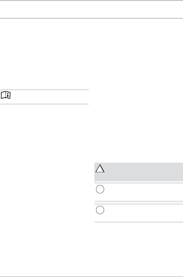
 1
1
D0000034797
1 Recessed grips
Transport from vehicle to installation room
The cardboard box has reinforced recessed grips along the top of the appliance. You can use these recessed grips, as well as the pallet at the lower end, to carry the appliance into the installation room. Take note of the weight of the appliance and ensure a sufficient number of personnel is available for handling the appliance.
9.2Storage
If it is necessary to store the appliance for a prolonged period before installation, observe the following information:
-Only store the appliance in a vertical position. Never store the appliance horizontally.
-Store the appliance in a location that is dry and largely dust-free.
-Protect the appliance from coming into contact with corrosive substances.
9.3Installation site
The appliance is not approved for outdoor installation except for garages.
To prevent appliance damage:
-The installation location must be free from flammable, highly combustible gases and substances, as well as high levels of dust.
- The installation room must be free from the risk of frost. |
|
|
- The intake temperature of the appliance must be within the |
ENGLISH |
|
permissible application limits (See 15.3, “Data table”, pg. |
||
|
||
29). |
|
|
- The floor of the installation room must be level and have suf- |
|
|
ficient load bearing capacity. Take note of the weight of the |
|
|
|
||
appliance with a full DHW tank (See 15.3, “Data table”, pg. |
|
|
29). A floor with insufficient foundation pressure capacity |
|
|
is in danger of collapse. If the appliance is not evenly bal- |
|
|
anced, there may be a risk of appliance damage. |
|
|
- The size of the installation room must correspond to the |
|
|
application limits of the appliance (See 9.5, “Minimum clear- |
|
|
ances”, pg. 18 and See 15.3, “Data table”, pg. 29). |
|
|
- Observe the safety clearances and protection zones. |
|
|
- Always leave sufficient distance to provide access for instal- |
|
|
lation, maintenance and cleaning. Observe the required min- |
|
|
imum clearances (See 9.4, “Siting the appliance”, pg. 18). |
|
|
- Ensure that the operation of other equipment in the installa- |
|
|
tion room is not impaired. |
|
|
- To reduce the pipe runs, install the unit close to the kitchen |
|
|
or bathroom. |
|
|
- To prevent disturbance from operating noise, never install |
|
|
the appliance close to bedrooms. |
|
The following installation locations are not permissible, due to risk of appliance damage:
-Locations where the air is contaminated with oil or salt
-Saline environments
-Areas in proximity to high frequency machines
-Places where the air contains ammonia (e.g. sewage works)
-Places where the air contains chlorine (e.g. swimming pools)
-Generally places where the air is strongly contaminated, e.g. due to dust, or contains aggressive substances
Note
The performance data indicated for this appliance has been determined in line with the relevant standard at an air temperature of 59°F/15°C). Below this temperature, the efficiency of the appliance decreases.
Note
It is possible to improve the efficiency of the appliance by utilizing the waste heat and humidity from other appliances to heat the DHW tank, e.g. boilers, tumble dryers or freezers.
Sound emissions
The air intake and air discharge sides of the appliance emit more noise than other sides of the housing.
Never direct the air intake or air discharge towards noise-sensitive rooms of the house, e.g. bedrooms.
Note
For details on noise emission, see chapter "See 15.3, “Data table”, pg. 29".
www.stiebel-eltron-usa.com |
Accelera® 220-300 E | 17 |
INSTALLATION
Preparations
9.4Siting the appliance
Carefully undo the cardboard packaging at the clips.
1
D0000034797
1 Cardboard packaging clips
The appliance is secured to the pallet with metal brackets and screws. The metal brackets are hooked on to the feet underneath the floor plate of the appliance.
1
1. |
2. |
D0000034798
1 Metal bracket fixing bolt
Remove the fixing bolts of the metal brackets from the pallet.
Push the metal brackets a little towards the tank center, to unhook them from the appliance feet.
Pull the metal brackets out from underneath the appliance.
Material losses
!Take note of the appliance's weight and top-heaviness.
Slightly tip the appliance and carefully roll the appliance off the pallet.
Bring the appliance in its final location.
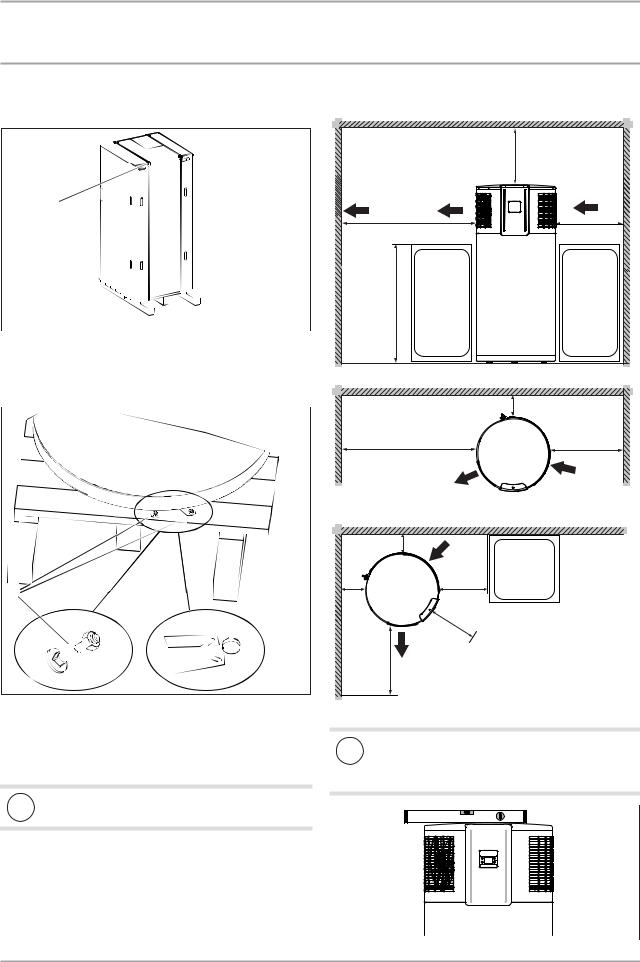
9.5Minimum clearances
Minimum room volume: |
14˝ |
|
800 ft2, 10´ x 10´ x 8´ |
||
(22.7 m2, 3 m x 3 m x 2.4 m) |
(0.4 m) |
|
|
|
Air flow |
Air flow |
intake |
|
|
||
exhaust |
|
|
6´ (1.8 m) |
2´ (0.6 m) |
|
|
An object |
|
|
next to the |
|
|
unit must |
|
≤42˝ |
be less than |
|
(1.1 m) |
42˝ high |
|
Acceptable positioning, vent parallel to a wall:
|
8˝ (0.2 m) |
|
6´ (1.8 m) |
2´ (0.6 m) |
|
Air flow |
Air flow |
|
exhaust |
||
intake |
||
|
Acceptable positioning, vent parallel to a wall in a corner:
8˝ (0.2 m) |
|
|
Air flow |
|
intake |
8˝ |
2´ |
(0.2 m) |
(0.6 m) |
|
|
|
2´ |
|
(0.6 m) |
6´ |
Air flow |
(1.8 m) |
exhaust |
Maintain the minimum clearances.
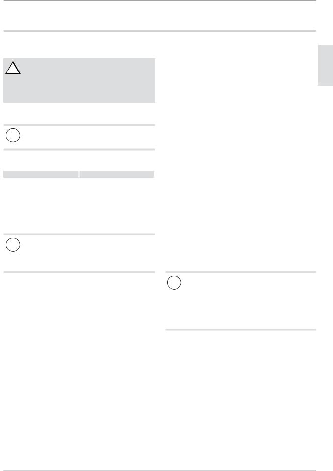
Material losses
!The top of the appliance should be made horizontal. Level the appliance horizontally using the height-ad-
justable feet.
D0000034806
18 | Accelera® 220-300 E |
www.stiebel-eltron-usa.com |
INSTALLATION
Installation
10. Installation
WARNING Injury
! Incorrect installation can lead to serious personal injury or material losses.
Before any work, ensure sufficient clearances for the installation.
Handle sharp-edged components carefully.
10.1 Water connection
Material losses
!Carry out all water connection and installation work in accordance with local plumbing regulations.
The following material combinations are approved for pipework installations:
Cold water inlet |
|
DHW outlet |
Copper pipe |
|
Copper pipe |
maximum pressure in the cold water supply line is higher, install a pressure reducing valve.
Check valve
Install a check valve in the cold water line (after the pressure reducing valve if installed). This check valve is necessary to prevent water from flowing backwards into the cold water piping.
Drain valve
Install a suitable drain valve at the lowest point in the cold water inlet line.
DHW circulation
The heat losses incurred in a DHW circulation line and the electrical power consumption of the circulation pump reduce the efficiency of the system. The cooled water in a circulation line mixes with the tank content. Where possible, avoid installing a DHW circulation line. Where that is not possible, the DHW circulation pump must be controlled thermally or by time switch.
Steel pipe |
|
Steel pipe or copper pipe |
PEX tubing |
|
PEX tubing |
Thoroughly flush the pipework before connecting the appliance. Foreign bodies, such as welding pearls, rust, sand or sealant can impair the operational reliability of the appliance.
Material losses
!To protect the connection nipples against corrosion the water tube connection must be made with plumber’s thread seal tape (PTFE). The use of hemp on nipple threads is not permissible.
Safety valve
The appliance is a sealed unvented DHW tank. The appliance is supplied with a temperature and pressure relief valve that has been factory installed and leak-tested.
Install a type-tested safety valve in the cold water supply line. The response pressure of the safety valve must be below or equal to the permissible operating pressure of the DHW tank.
The safety valve protects the appliance against unacceptable excess pressure.
Ensure that the expansion water escaping from the safety valve can drip into a drain, e.g. a tank or sink.
Ensure the drain cannot be shut off.
Size the drain in a way that water can drain off unimpeded when the safety valve is fully opened.
Ensure that the discharge pipe of the safety valve is open to atmosphere.
Fit the discharge pipe of the safety valve with a constant downward slope and in a room free from the risk of frost.
Pressure reducing valve
The maximum pressure in the cold water supply line must be at least 20% below the response pressure the safety valve. If the
Thermal insulation
Insulate the DHW line against heat loss in accordance with locally applicable regulations.
10.2 Condensate drain
Install a condensate drain hose to remove the condensate which forms.
Connect the condensate drain included in the standard delivery to the “condensate drain” connection.
Connect a condensate drain hose to the condensate drain bend.
Material losses
!Ensure condensate drain cannot retain water.
Use a condensate drain hose with a diameter great-
er than the diameter of the condensate drain bend. Ensure the condensate drain hose is not bent. Route the condensate drain hose with a continuous
base slope.
The condensate drain must be open to the atmosphere.
Use a suitable condensate pump if there is insufficient base slope. Observe the building characteristics.
ENGLISH
www.stiebel-eltron-usa.com |
Accelera® 220-300 E | 19 |
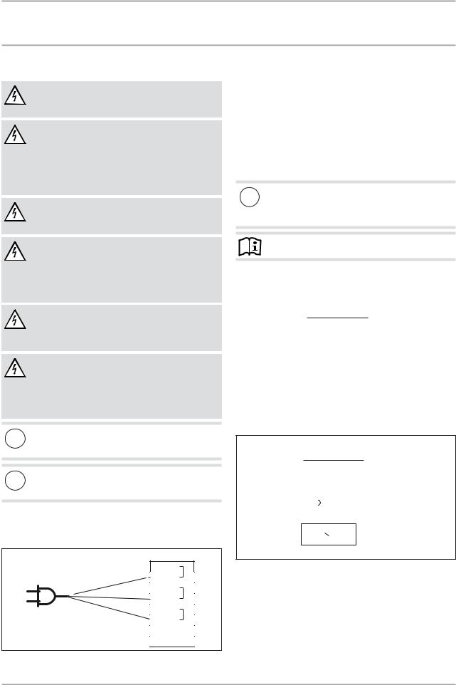
INSTALLATION
Installation
10.3 Power supply
WARNING Electrocution
Carry out all electrical connection and installation work in accordance with national and regional regulations.
WARNING Electrocution
If the appliance is permanently connected to the power supply, ensure that the appliance can be separated from the power supply by an isolator that disconnects double terminal with at least 1/8˝/4 mm contact gap. Contactors, disconnect switches or circuit breakers can be used for this.
WARNING Electrocution
Observe the safety regulations to prevent contact with dangerous 'live' parts.
WARNING Electrocution
Coming into contact with 'live' components presents a threat to life. Disconnect the appliance from the power supply before carrying out work on the control panel. Prevent the power supply from being switched on while you are working on the system.
WARNING Electrocution
Insufficient grounding can lead to electrocution. Ensure the appliance is grounded according to locally applicable requirements.
WARNING Electrocution
The power cable must only be replaced (for example if damaged) with an original spare part by a qualified contractor authorized by the manufacturer. For an original spare part contact Stiebel Eltron 800-582-8423 for part number 315650.
Material losses
! The voltage to the appliance must match the voltage specified on the type plate.
Material losses
! Never connect the appliance to the power supply before the DHW tank is filled.
Standard connection without external signal transmitter
X0 |
|
PE |
|
PE |
|
N |
|
N |
|
L1 |
|
L1 |
D0000034487 |
FB |
|
LF |
|
10.3.1 Connection with external signal transmitter
An external potential free signal transmitter for controlling DHW temperature (set temperature 2) can be connected to terminal X0/LF.
In the delivered status, terminal X0/LF is not assigned. If this terminal is connected to 240 V AC, the appliance activates set temperature 2.
Following a one-off activation (the external signal is present for at least one minute), set temperature 2 applies for at least 20 minutes.
Material losses
!If the 240 V AC signal of an external signal transmitter is to be connected to terminal X0/LF, do not interchange phase and neutral.
Note
Never wire up terminal X0/FB.
Example 1: Power-OFF signal with own 240 V AC phase
|
|
|
|
|
|
X0 |
|
||
PE |
|
PE |
|
|
|
||||
|
|
|
|||||||
|
|
|
|
|
|||||
|
PE |
|
|
|
|||||
|
|
|
|
|
|
|
|
|
|
|
|
|
|
|
|
|
|
|
|
N |
|
|
|
|
|
N |
|
|
|
|
|
|
|
|
|
|
|||
|
|
|
|
|
|
|
|
|
|
|
|
|
|
N |
|
|
|
||
|
|
|
|
|
|||||
|
|
|
|
|
|
L1 |
|
|
|
|
|
|
|
|
|
|
|
||
|
|
|
|
|
|
|
|
|
|
L1 |
|
|
|
|
L1 |
|
|
D0000034589 |
|
|
|
|
|
|
|||||
EVU: L1, L2 oder L3 |
|
|
|
|
|||||
|
LF |
||||||||
|
|
|
|
|
|
|
|||
|
|
|
|
|
|
|
|
|
|
|
|
|
|
|
|
FB |
|
||
|
|
|
|
|
|
||||
|
|
|
|
|
|
|
|
|
|
|
|
|
|
|
|
|
|
|
|
Example 2: Photo-voltaic signal via on-site relay and phase routed outside the appliance
|
|
|
|
|
|
|
X0 |
||||
|
|
|
|
|
|
|
PE |
|
|
|
|
|
|
|
|
|
|
|
|
|
|
||
|
|
|
|
|
|
|
|
|
|
|
|
PE |
|
PE |
|
|
|
|
|||||
|
|
|
|
||||||||
N |
|
|
|
|
|
|
N |
|
|
|
|
|
|
|
|
|
|
|
|
|
|||
|
|
|
|
|
|
N |
|
|
|
|
|
|
|
|
|
|
|
|
|
|
|||
|
|
|
|
|
|
|
L1 |
|
|
|
|
|
|
|
|
|
|
|
|
|
|
|
|
|
|
|
|
|
|
|
|
|
|
|
|
L1 |
|
|
|
|
|
|
L1 |
|
|
|
|
|
|
|
|
|
|
|
LF |
|
|
||
|
|
|
|
|
|
|
|
|
|||
|
|
|
|
|
|
|
FB |
|
D0000034590 |
||
1 |
|
|
|
|
|
|
|
|
|
||
|
|
|
|
|
|
|
|
|
|||
1 Inverter (floating contact)
The inverter power feed is located at a central distribution point (e.g. in the main fuse box).
20 | Accelera® 220-300 E |
www.stiebel-eltron-usa.com |
INSTALLATION
Commissioning
Connection to terminal block X0
Remove the appliance cover (See 14.1, “Removing the appliance cover”, pg. 23).
1
D0000034803
1 Terminal X0
Prepare the leads for connection to X0 in such a manner that each lead terminating at X0 has a wire ferrule.
Route leads through the strain relief.
Connect the leads to X0 (see chapter "See 10.3.1, “Connection with external signal transmitter”, pg. 20).
10.4 Assembling the appliance
Note
Refit the appliance cover after completing your work. See chapter "See 14.10, “Fitting the appliance cover”, pg. 25).
11. Commissioning
11.1 Commissioning
Material losses
!Never connect the appliance to the power supply before the DHW tank is filled.
Note
At temperatures below 5°F/-15°C, the high limit safety cut-out may respond. The appliance may be subjected to these temperatures during storage or transport.
If required, press the high limit safety cut-out reset button. See 13.3, “Resetting the high limit safety cut-out”, pg. 22
|
|
Note |
|
ENGLISH |
|
|
|||
|
|
the electronic main board to initialize. |
||
|
|
After an interruption of the power supply, compressor op- |
|
|
|
|
eration remains blocked for at least one minute to allow |
|
|
|
|
If the compressor subsequently fails to start, it may be |
|
|
|
|
disrupted by additional safety devices (Klixon and high |
|
|
|
|
|
||
|
|
pressure switch). This interruption due to the compressor |
|
|
|
|
motor klixon is terminated automatically. |
|
|
|
|
If the high pressure switch responds, it can be manually |
|
|
|
|
reset after the pressure is less than 246 PSI. This normally |
|
|
|
|
occurs 5 minutes after responding. |
|
|
|
|
|
|
|
11.1.1 |
Filling the DHW tank |
|
||
Fill the DHW tank and vent the pipework by following the proce- |
|
|||
dure below: |
|
|||
Close the drain valve. |
|
|||
Open all DHW tap points and the shut-off valve in the cold |
|
|||
water supply. |
|
|||
Close the DHW tap points as soon as water starts to emerge |
|
|||
from them. |
|
|||
11.1.2 |
Settings / function check |
|
||
To check the function, select the maximum set temperature. |
|
|||
A higher set temperature allows for more mixed water but lower |
|
|||
efficiency. A lower set temperature is more efficient but less |
|
|||
mixed water is available. Never reduce the set temperature below |
|
|||
122°F/50°C to reduce problems with legionella. |
|
|||
11.1.3 |
Appliance handover |
|
||
Explain the appliance function to users and familiarize them |
|
|||
with its operation. |
|
|||
Make users aware of potential dangers, especially the risk of |
|
|||
scalding. |
|
|||
Make users aware of critical environmental factors and re- |
|
|||
quirements concerning the installation location. |
|
|||
Inform users that water may drip from the safety valve |
|
|||
during the heating operation. |
|
|||
Hand over these operating and installation instructions to |
|
|||
users for safe-keeping. |
|
|||
11.2 |
Recommissioning |
|
||
If the appliance is switched off due to an interruption to the power supply, no specific measures for restarting are required once the power supply has been restored. The appliance has saved the parameters most recently set and continues operating with these.
If the comfort heating function was active before interruption of the power supply, this is reactivated with a set temperature of 149°F/65°C once the power supply has been established again.
Remote function is not reactivated after an interruption of the power supply.
www.stiebel-eltron-usa.com |
Accelera® 220-300 E | 21 |
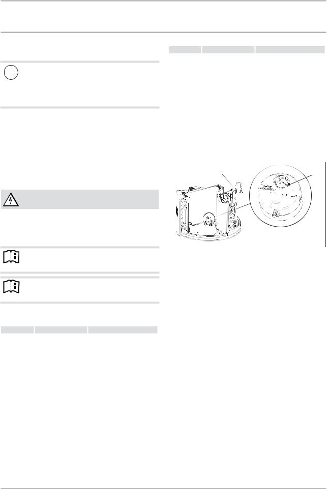
INSTALLATION Shutting down
12. Shutting down
Material losses
! If the appliance is disconnected from the power supply, it is no longer protected against frost.
Only disconnect the appliance from the power supply for longer periods if you are also draining the DHW tank.
If there is no usage of hot water for a long period of time, always drain the DHW tank. See chapter "See 14.4, “Draining the tank”, pg. 24".
The appliance can only be switched off by interrupting the power supply.
Pull the plug from the socket or disconnect the circuit breaker to the appliance.
13. Troubleshooting
WARNING Risk of electrocution
Prior to all work on the appliance, turn off all power to it.
For work inside the appliance, remove the appliance cover (See 14.1, “Removing the appliance cover”, pg. 23).
If necessary, remove the upper section of the casing jacket (See 14.2, “Removing the casing ring”, pg. 23).
Note
Refit the casing ring after completing the work. See 14.9, “Fitting the casing ring”, pg. 24.
Note
Refit the appliance cover after completing your work. See 14.10, “Fitting the appliance cover”, pg. 25.
13.1 Fault table
Fault |
Cause |
|
Remedy |
|
The appliance |
Excessive pressure in |
|
Eliminate the cause of the in- |
|
switches off |
the refrigerant circuit. |
|
crease in pressure in the refriger- |
|
unexpectedly |
The safety pressure lim- |
|
ant circuit. |
|
and does not |
iter has responded. The |
|
Wait approx. 5 to 15 minutes for |
|
switch on |
compressor has been |
|
the appliance to equalize the |
|
again. |
switched off. |
|
pressure. Reset the safety pres- |
|
|
|
|
|
sure limiter (See 13.2, “Resetting |
|
|
|
|
the safety pressure limiter”, pg. |
|
|
|
|
22). |
|
The appliance is operated |
|
Ensure that the operation limit is |
|
|
outside the operation |
|
observed. |
|
|
limit. The ambient tem- |
|
Wait approx. 5 to 15 minutes for |
|
|
perature is higher than |
|
the appliance to equalize the |
|
|
the permissible value. |
|
pressure. Reset the safety pres- |
|
|
The safety pressure limit- |
|
sure limiter (See 13.2, “Resetting |
|
|
er has responded. |
|
the safety pressure limiter”, pg. |
|
|
|
|
|
22). |
The compres- |
The thermal load of the |
|
Remedy the cause of the high |
|
sor switches off |
compressor has been ex- |
|
thermal load. Wait until the appli- |
|
unexpectedly. |
ceeded. The motor over- |
|
ance restarts. |
|
|
load relay has responded. |
|
|
|
Fault |
Cause |
|
Remedy |
|
The appliance |
An inadequate air flow |
|
Check whether the fan is contam- |
|
generates less |
across the evaporator |
|
inated. Check whether the evapo- |
|
heat. |
may be a possible cause. |
|
rator is contaminated. Ensure that |
|
|
|
|
|
supply and extract air flow are |
|
|
|
|
unimpeded. |
For explanations of the fault codes, See 6.1, “Fault codes”, pg. 15.
13.2 Resetting the safety pressure limiter
The safety pressure limiter shuts down the compressor if the pressure inside the refrigerant circuit exceeds the permissible maximum value. The safety pressure limiter may also respond if the appliance is operated above its permissible application limit or the temperature controller of the heat pump fails to respond.
1 |
2 |
D0000034801
1 Reset button for safety pressure limiter 2 Reset button for high limit safety cut-out
After removing the cause of the fault, reset the safety pressure limiter by pressing the reset button.
13.3 Resetting the high limit safety cut-out
The high limit safety cut-out protects the appliance from overheating. The electric booster element switches off when the tank water temperature exceeds 188±10 °F / 87±5 °C.
Once the cause of the fault has been removed, press the reset button of the high limit safety cut-out on the rod thermostat. To do so, remove the appliance cover.
13.4 Motor overload relay
In the event of excessive thermal load of the compressor, the motor overload relay switches the compressor off.
Remove the cause.
After a short cooling period, the motor overload relay will restart the compressor automatically.
22 | Accelera® 220-300 E |
www.stiebel-eltron-usa.com |

INSTALLATION Maintenance and cleaning
14. Maintenance and cleaning
WARNING Electrocution
Prior to all work on the appliance, turn off all power to it.
ENGLISH
14.1 Removing the appliance cover
D0000035322
Undo the screw (Torx) that fastens the control panel and the appliance cover to the appliance.
Push the control panel upwards.
D0000034802
Remove the control panel.
A lead connects the operating controls to the appliance ECB. If necessary, pull the plug from the back of the control panel to fully remove the control panel.
Carefully lift away the appliance lid and undo the ground wire that runs from the appliance control panel to the cover.
Note
Refit the appliance cover after completing your work. See 14.10, “Fitting the appliance cover”, pg. 25.
14.2 Removing the casing ring
Note
If you require more space to work inside the appliance, you can remove the casing on the upper section of the appliance.
1 |
D0000034803 |
|
1 Fixing screws on casing ring
The casing ring is fastened with screws. Undo the fixing screws on the casing.
Remove the condensate drain bend and pipe collar of the drain. Turn anti-clockwise to undo.
Material losses
!A ground wire is connected to the inside of the casing ring. The casing can only be removed after the ground wire has been detached.
D0000034814
The casing ring overlaps along the joint. A tab on one end clips into the recess on the other end of the casing ring.
Ease the casing ring apart, until it can be removed or slid downwards.
Note
Refit the casing ring after completing the work. See 14.9, “Fitting the casing ring”, pg. 24
www.stiebel-eltron-usa.com |
Accelera® 220-300 E | 23 |
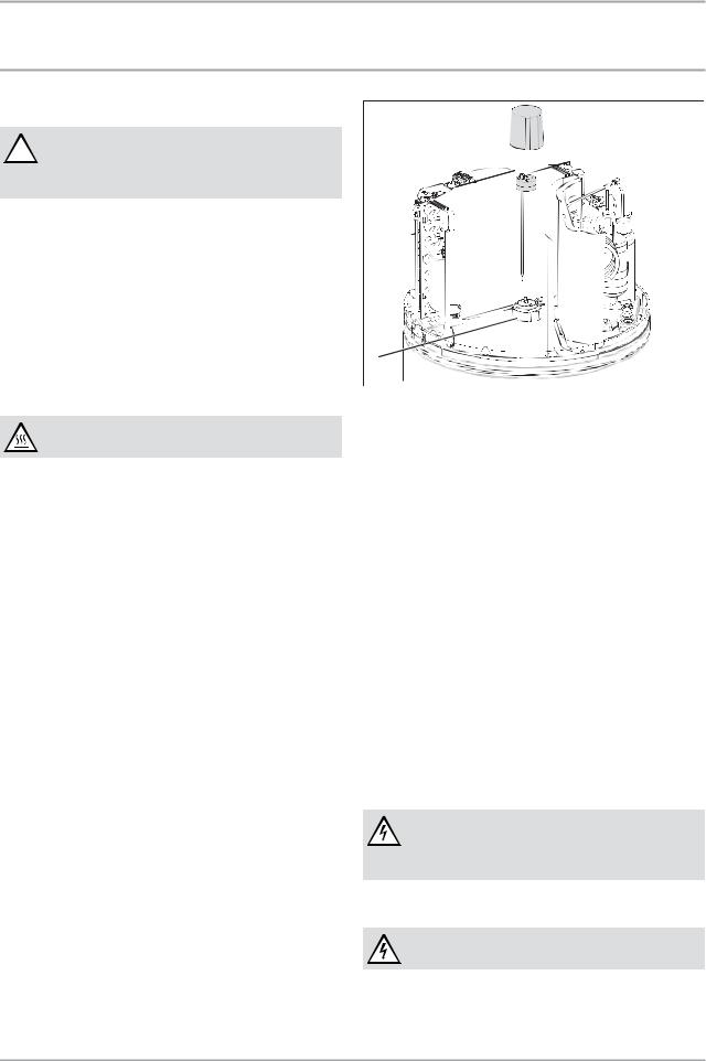
INSTALLATION Maintenance and cleaning
14.3 Cleaning the evaporator
WARNING Injury
! The evaporator consists of numerous sharp-edged fins.
Be careful during cleaning the evaporator and wear protective clothing, especially safety gloves.
The evaporator fins are coated with a hydrophilic coating to reduce corrosion and to eliminate surface tension on condensed water droplets. This creates a self-cleaning action so minimal cleaning is necessary. Nevertheless, the evaporator should still be checked for contamination and corrosion and cleaned as necessary.
Undo the screw that secures the appliance cover at the upper side of the control panel.
Remove the control panel and the appliance cover.
Carefully clean the evaporator fins. Use water and a soft brush for this. Never use acidic or alkaline cleaning agents.
14.4 Draining the tank
WARNING Burns
Hot water may escape when draining the DHW tank.
To drain the DHW tank, e.g. when shutting the appliance down, proceed as follows:
Unplug the appliance from the power supply. Close the shut-off valve in the cold water supply line.
The DHW tank is drained via the cold water supply line.
Open the drain valve installed in the cold water supply line (See 10.1, “Water connection”, pg. 19). If no drain valve has been installed, undo the cold water supply line at the “cold water inlet” connection.
Open one tap in one sink.
Some residual water will remain in the lower section of the DHW tank.
14.5 Descaling the electric booster element
Only descale the flange of the electric booster element after removing it, and never treat the interior of the DHW tank and the impressed current anode with descaling agents. The electric booster element is screwed into the appliance at a central point at the top.
1 |
D0000034799 |
|
1 Electric booster element with protective anode
14.6 Protective anode
The flange of the electric booster element is equipped with a protective anode that protects the appliance from corrosion while it is connected to the power supply. The protective anode is a maintenance-free impressed current anode.
If a fault code in the display indicates that the protective anode is faulty, proceed as follows:
Remove the controller of the electric booster element. Check the protective anode connector and its wiring. Refit the controller of the electric booster element.
14.7 Valves
Regularly check the system's valves (safety valve, pressure reducing valve, drain valve, vacuum breaker, mixing valve), to ensure the operational reliability of the appliance. The amount of lime-scale deposits depends on local water quality.
Check all valves in the system and remove lime-scale deposits.
Replace the valves if necessary. Check the function of the valves.
14.8 Replacing the power cable
WARNING Electrocution
If the power cable is faulty, replace it with a new one. The power cable should only be replaced by a qualified contractor.
14.9 Fitting the casing ring
WARNING Electrocution
Reconnect the ground wire to the casing ring.
24 | Accelera® 220-300 E |
www.stiebel-eltron-usa.com |
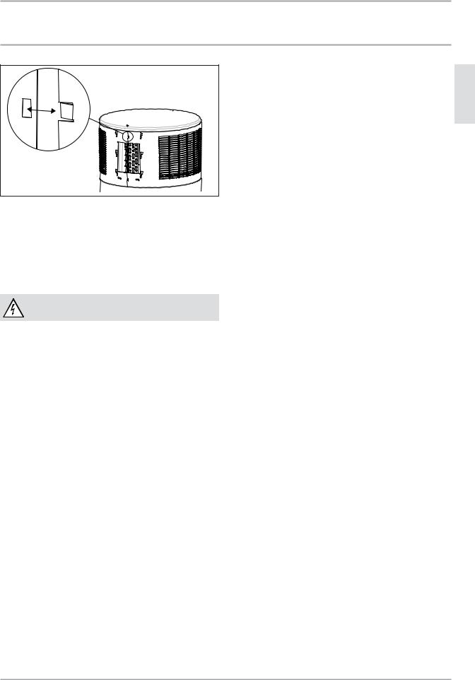
INSTALLATION
Maintenance and cleaning
ENGLISH
D0000034814
Fit the upper casing ring. The casing ring overlaps along the joint. A tab on one end clips into the recess on the other end of the casing ring.
Secure the casing ring with screws.
Fit the pipe collar of the condensate drain and the condensate drain bend.
14.10 Fitting the appliance cover
WARNING Electrocution
Reconnect the ground wire to the appliance cover.
Place the lid back on the appliance top.
Connect the ground cable to the signed ground terminal.
Connect the cable linking the control with the appliance ECB to the back of the panel.
Insert the control panel.
Secure the appliance cover and the control panel using the screw at the top of the control panel.
www.stiebel-eltron-usa.com |
Accelera® 220-300 E | 25 |
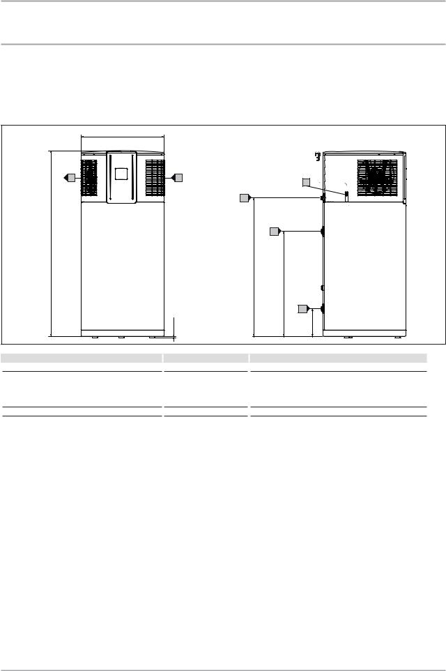
INSTALLATION
Specification
15. Specification
15.1 Dimensions and connections
15.1.1 Accelera 220 E
27 |
/8˝ |
|
1 |
(690 mm)
|
F |
E |
|
|
A |
|
|
|
|
|
|
|
|
D |
|
|
|
60 |
/4˝ |
|
C |
|
|
|
3 |
|
|
|
|
(1545 mm) |
|
|
|
|
|
|
|
45 |
/8˝ |
|
|
|
|
|
5 |
|
|
|
|
(1160 mm) |
/4˝ |
|
|
|
|
|
34 |
|
|
|
|
|
|
3 |
|
|
|
|
(884 mm) |
|
|
|
|
|
|
B |
|
|
|
1 |
|
9 |
/2˝ |
|
|
/2 – 1˝ |
|
|
1 |
|
|
|
(241 mm) |
||
|
|
(8–24 mm) |
|
||
|
|
|
|
|
|
Accelera 220 electronic
AEntry electrical cables
B |
Cold water inlet |
|
Male thread |
|
1˝ NPT |
C |
DHW outlet |
|
Male thread |
|
1˝ NPT |
D |
Condensate drain |
|
Male thread |
|
¾˝ NPT |
EAir intake
FAir discharge
26 | Accelera® 220-300 E |
www.stiebel-eltron-usa.com |
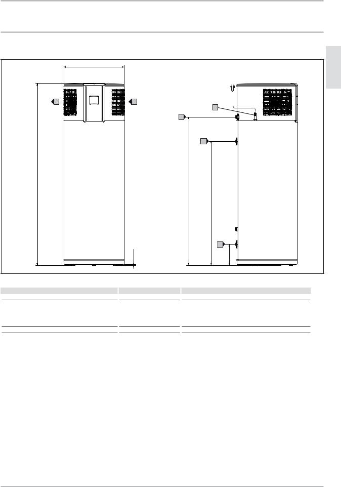
INSTALLATION |
|
|
|
|
|
Specification |
|
|
|
|
|
15.1.2 |
Accelera 300 E |
|
|
|
ENGLISH |
|
27 |
/8˝ |
|
|
|
|
|
1 |
|
|
|
|
(690 mm) |
|
|
|
|
|
F |
E |
|
A |
|
|
|
|
|
|
|
|
|
D |
|
|
|
|
|
|
C |
|
|
|
75 /8˝ |
|
|
|
|
|
3 |
|
|
|
|
|
(1913 mm) |
|
|
|
|
|
|
60 |
/8˝ |
|
|
|
|
|
1 |
|
|
|
|
(1528 mm) |
/4˝ |
|
|
|
|
|
49 |
|
|
|
|
|
|
1 |
|
|
|
|
(1252 mm) |
|
|
|
|
|
|
B |
|
|
|
1/2 – 1˝ |
|
9 |
/2˝ |
|
|
|
|
|
1 |
|
|
(8–24 mm) |
|
(241 mm) |
|
|
|
|
|
|
|
Accelera 300 electronic
AEntry electrical cables
B |
Cold water inlet |
|
Male thread |
|
1˝ NPT |
C |
DHW outlet |
|
Male thread |
|
1˝ NPT |
D |
Condensate drain |
|
Male thread |
|
¾˝ NPT |
EAir intake
FAir discharge
www.stiebel-eltron-usa.com |
Accelera® 220-300 E | 27 |
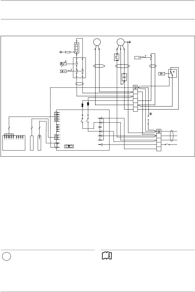
INSTALLATION
Specification
15.2 Wiring diagram
|
|
|
|
|
|
|
|
M2 |
M |
|
|
M1 |
M |
|
|
|
|
|
|
|
|
|
|
E1 |
|
|
|
|
|
|
|
|
|
|
|
||
|
|
|
|
|
|
|
|
1~ |
|
|
|
1~ |
|
|
|
|
||
|
|
|
R1 |
|
|
|
|
L |
|
N |
|
C |
R |
S |
|
|
|
|
|
|
|
|
|
|
|
|
|
|
|
|
|
|
|
|
|
|
|
|
|
|
|
|
|
|
|
|
|
|
F2 |
3 |
|
|
F3 |
|
|
|
|
|
|
|
|
|
|
|
|
|
|
|
|
|
|
|
|
||
|
|
|
|
|
1 |
2 |
|
|
|
|
|
|
|
|
p |
|
|
|
|
|
|
|
|
|
|
|
|
|
|
|
|
|
|
|
|
||
|
|
|
N1 |
|
|
|
|
|
|
|
|
1 |
|
|
|
|
|
|
|
|
|
|
|
|
|
|
|
|
|
|
|
|
|
|
|
|
|
|
|
|
F1 |
|
|
|
|
br |
bl |
|
|
bl |
br |
sw |
N2 |
4 |
2 |
|
|
|
|
|
|
|
|
|
|
|
|
|
|
|
|
||||
|
|
|
|
|
|
|
|
|
|
|
|
|
|
|
|
|
||
|
|
|
|
|
A |
B |
|
|
|
|
|
|
|
|
Z1 |
|
3 |
|
|
|
|
|
|
|
|
|
|
|
|
|
|
|
|
|
|||
|
|
|
|
|
|
|
|
|
|
|
|
|
|
|
|
|
||
|
|
|
|
|
sw |
sw |
|
|
|
|
|
|
|
|
|
|
|
|
|
|
|
|
|
|
|
|
|
|
|
|
|
|
|
X1 |
|
|
|
|
|
|
|
|
|
|
|
|
|
|
|
|
|
|
5 |
|
|
|
|
|
|
|
|
|
|
|
|
|
|
|
|
|
|
4 |
|
|
|
|
|
|
|
|
|
|
|
|
|
|
|
|
|
|
3 |
|
|
|
|
|
|
|
|
|
V1 |
V2 |
|
|
|
|
|
|
2 |
|
|
|
|
|
|
|
|
|
|
|
|
|
|
|
|
|
|
|
|
|
||
|
|
|
A1 |
|
|
sw |
|
rt |
|
|
|
|
|
|
1 |
|
|
|
|
|
|
|
|
|
|
|
|
|
|
|
|
|
|
|
|
|
|
|
|
|
X2 |
|
|
|
X4 |
X5 |
|
X6 |
FB |
|
|
|
Tank |
|
|
|
|
|
|
|
|
K2 |
|
K3 |
|
|
|
|
|
|
|
||||
|
|
|
|
|
|
|
|
|
|
|
|
|
|
|
||||
|
|
|
|
|
|
|
|
|
|
|
|
|
Cap |
|
|
|
||
|
|
|
|
|
|
|
|
|
|
|
L1 |
|
|
|
|
|
|
|
|
|
|
|
|
|
|
|
|
|
|
|
|
|
Outer jacket |
|
|
|
|
|
|
|
|
|
|
|
|
|
|
|
CB |
|
|
|
|
|
|
|
5 |
|
3 |
1 |
|
|
|
|
|
|
|
|
|
|
X0 |
|
|
|
|
|
|
|
|
|
|
|
|
|
|
|
|
|
|
|
||||
|
|
|
X12 |
|
|
|
|
|
|
|
L3 |
|
|
|
|
gnge |
|
|
|
|
|
|
|
|
|
|
|
|
|
|
|
|
|
PE |
|
||
|
A2 |
B1 |
G1 |
|
|
|
|
|
|
|
|
|
|
|
|
|
|
|
|
|
|
|
|
|
|
|
N |
|
|
|
N |
sw 1 |
N |
315674-38055 |
|||
|
|
|
X10 |
|
|
|
|
|
|
|
|
|
|
|
|
|||
X2 |
X1 |
|
|
|
|
|
|
|
|
L2 |
|
|
|
L |
sw 2 |
L |
||
|
|
|
|
|
|
|
|
|
|
|
|
|
EVU |
|||||
|
|
|
|
|
|
|
|
X9 |
|
LF |
|
|
|
LF |
L LF |
|||
|
|
|
X7 |
|
|
|
|
|
|
|
|
|
||||||
|
|
|
|
|
|
|
|
|
|
|
|
|
||||||
|
|
|
|
|
|
|
|
|
|
|
|
|
|
|
|
|
||
|
|
|
E |
Z |
B |
|
|
|
|
|
|
|
|
|
FB |
|
|
|
|
|
|
12 |
|
|
|
|
|
|
|
|
|
|
|
|
|
|
|
A1 |
Electronic assembly (control unit) |
A2 |
Electronic assembly (programming unit) |
B1 |
Temperature sensor |
E1 |
Heating element (1.5 kW / 5120 BTU/h) |
F1 |
High limit safety cut-out TSR (87°C ±5 / 189°F ±8) |
F2 |
Motor protection switch M1 |
F3 |
High pressure switch (24 bar) |
G1 |
Impressed current anode |
LLF |
Optionally see Installation instructions |
M1 |
Compressor |
M2 |
Fan |
N1 |
Thermostat TSR (65°C ±5 / 149°F ±8) |
N2 |
Defrost controller |
R1 |
Resistor (380 ohms) |
X0 |
Mains terminal |
X1 |
Terminals |
Z1 |
Capacitor |
! |
Material losses |
|
|
Note |
If X0/LF is connected, the power supply to the appliance |
|
|
Never wire up terminal X0/FB. |
|
|
|
|||
|
must be a permanent connection (See 10.3.1, “Connec- |
|
|
|
|
|
|
|
|
|
tion with external signal transmitter”, pg. 20). Never |
|
|
|
|
interchange L1 and N. |
|
|
|
|
|
|
|
|
28 | Accelera® 220-300 E |
www.stiebel-eltron-usa.com |
 Loading...