


EVI-HD1
A-CKC-100-11(1)
HD Color Video Camera
Technical Manual
EVI-HD1
2006 Sony Corporation

Table of Contents
Features ..................................................................... 3
Connection................................................................. 4
Locations of Controls ............................................... 5
Basic Functions ......................................................... 8
Initial Settings and Position Preset ........................... 13
Mode Condition ........................................................ 14
Command List ......................................................... 19
VISCA RS-232C Commands ................................... 19
EVI-HD1 Commands ................................................ 26
Specifications .......................................................... 38
Precautions .............................................................. 40
2

• The CMOS video camera provides 2,000,000
effective picture elements (pixels) that can shoot
high-definition images to offer superior picture
quality.
•By adopting the DD motor mechanism, in addition to
high-speed pan/tilt action, improvement of the noise
reduction mechanism lets you use the camera for a
variety of purposes.
• The camera allows you to shoot an image using the
1080i high definition video format, which is
equivalent to an HD-TV broadcast.
The camera is compatible with 14 formats, including
59.94 Hz, 50 Hz and the SD video format.
• The camera outputs HD image, conforming to the
SMPTE292M serial digital interface standard. This
allows long distance transmission of high-quality
camera images.
• The camera is equipped with an RS-232C
communication interface. You can select the baud
rate of either 38400 bps or 9600 bps. This allows you
to remotely control the camera at a high
communication speed.
Overview
Features
3
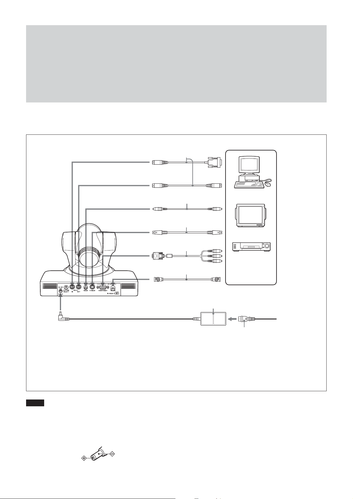
Connection
Connection
to VISCA IN
to VISCA OUT
to SD OUT VIDEO
to SD OUT
S VIDEO
to HD OUT
COMPONEN
to HD OUT HD-SDI
VISCA cable
(not supplied)
Video cable
(not supplied)
S-Video cable
(not supplied)
Connecting cable with
D-sub 15-pin connectors
(not supplied)
Connecting cable
T
with BNC connectors
(not supplied)
AC power adaptor
(supplied)
1)
to RS-232C
2)
to Video
input
to S-Video
input
to component
video input
to HD-SDI
Input
Computer, video
monitor, HD video
monitor, VTR, or
3)
HD CAM VTR with a
video input jack
to AC outlet
to DC IN 12V
Power cord (supplied)
1) When the camera is connected to a computer with a VISCA cable (cross type, RS-232C), you can operate
the camera with the computer. To obtain a cable, consult the dealer where you bought your camera.
2) To VISCA IN of other EVI-HD1s (when connecting to more than one camera)
3) The HD OUT COMPONENT output is not compatible with a computer display that does not support HDTV
formats.
Notes
• You cannot connect your Color Video Camera to a
computer that is not equipped with either video input or an
S-Video input connector.
• You have to set the video format of the signal to be output
from the camera. For detailed information on how to set
the video format, see “5 SYSTEM SELECT switch” on
page 5.
• Use only the AC power adaptor (JEITA type4) supplied
with the unit. Do not use any other AC power adaptor.
Polarity of the plug
4
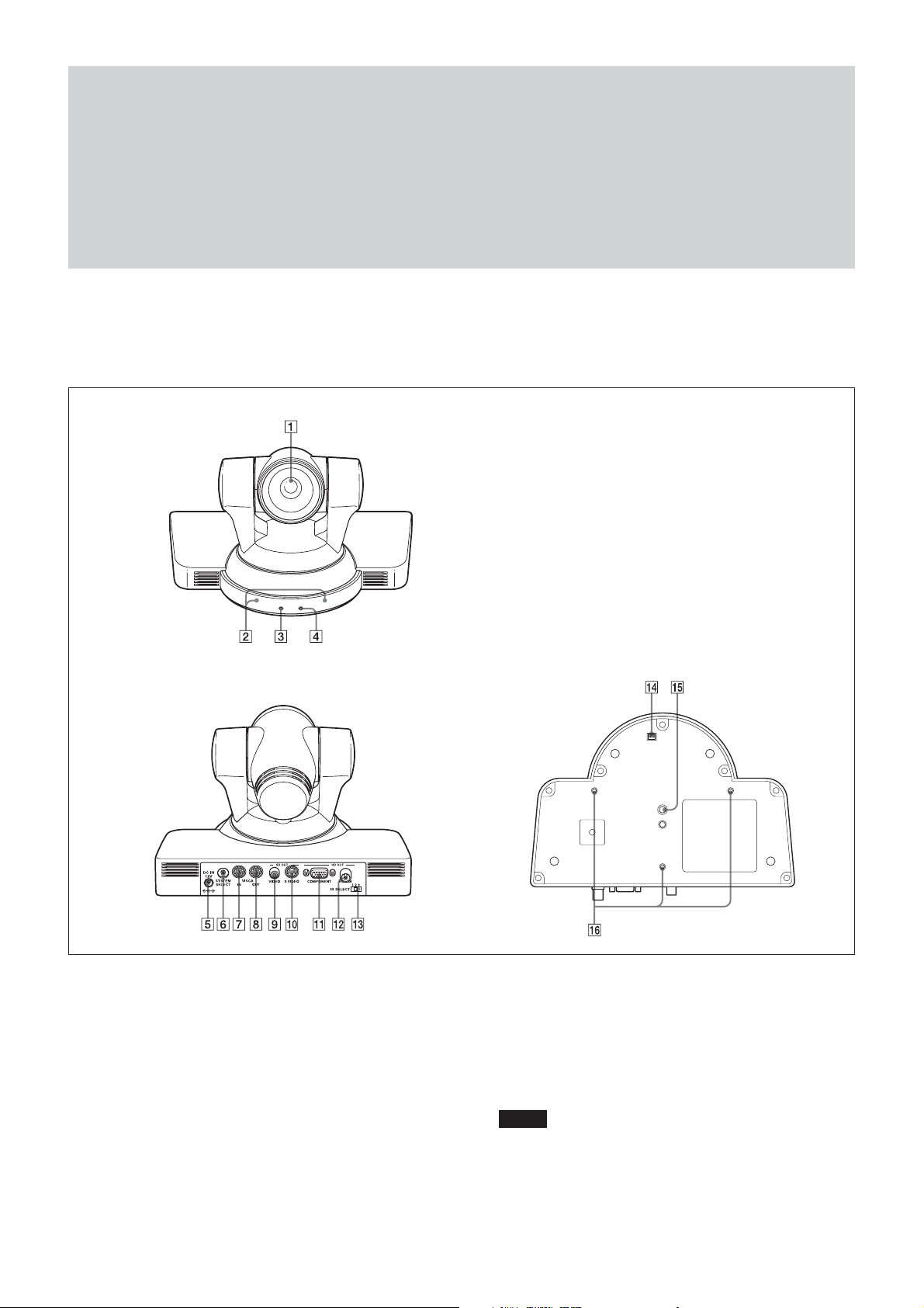
Main Unit
Front
Locations of Controls
Locations of Controls
Rear Bottom
1 Lens
2 Remote sensors
3 POWER lamp
4 STANDBY lamp
For detailed information on LED status of the POWER
lamp and STANDBY lamp, see “LED Status” on page 37.
5 DC IN 12V connector
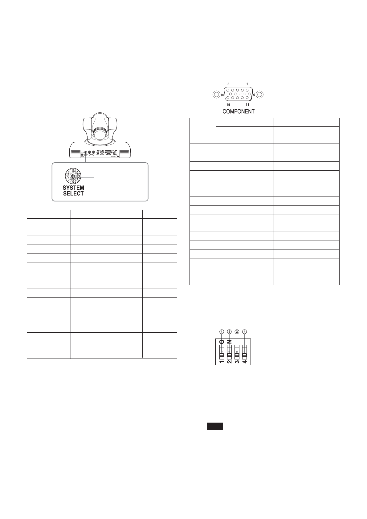
6 SYSTEM SELECT switch
This switch allows you to select the video format of the
signal to be output from the HD OUT COMPONENT, HD
OUT HD-SDI, SD OUT VIDEO and SD OUT S VIDEO
connectors.
Notes
• Be sure to set this switch before you turn on the power of
the camera. You can also set this switch in the standby
mode of the camera. After completing the setting, turn on
(Continued)
5
Locations of Controls
the power of the camera by connecting it to an AC outlet
using the supplied AC power adaptor and AC power
cord, or by using the VISCA command. When you set
this switch in the standby mode, press the POWER
switch of the remote commander. This switch setting
becomes effective.
• Be sure to use a Phillips-head screwdriver when
changing the switch position. If you use a tool other than
the designated screwdriver, the crossed groove may be
damaged.
Set this arrow to the
desired video format.
Switch position Video format HD OUT SD OUT
0 1080i/59.94 a —
1 1080p/29.97 a —
2 720p/59.94 a —
3 720p/29.97 a —
4 NTSC (LB) — a
5 NTSC (CR) — a
6 NTSC (SQ) — a
7 No output — —
8 1080i/50 a —
9 1080p/25 a —
A 720p/50 a —
B 720p/25 a —
C PAL (LB) — a
D PAL (CR) — a
E PAL (SQ) — a
F No output — —
7 VISCA IN connector
8 VISCA OUT connector
9 SD OUT VIDEO connector
0 SD OUT S VIDEO connector
qa HD OUT COMPONENT connector
Pin No. Function
At YPbPr COMPONENT At YPbPr COMPONENT
setting (at SYNC) setting (at VD)
0 Pr-OUT Pr-OUT
1 Y-OUT Y-OUT
2 Pb-OUT Pb-OUT
3 GND GND
4 GND GND
5 GND GND
6 GND GND
7 GND GND
8 GND GND
9 No connection No connection
10 GND GND
11 GND GND
12 No connection No connection
13 HD-OUT HD-OUT
14 Tri-level SYNC-OUT Bi-level VD-OUT
15 No connection No connection
qs HD OUT HD-SDI connector
qd IR SELECT switch
qf BOTTOM switches
a: Outputs the image signal.
—: Does not output the image signal
LB: Abbreviation of LETTER BOX. A video signal
with the 16:9 aspect ratio is output by adding a blank
area (no signal, black) top and bottom to display the
image without distortion on a monitor that uses the 4:3
aspect ratio.
CR: Abbreviation of CROP. A video signal with the
4:3 aspect ratio is output, by cropping both the left and
right sides of a video image with a 16:9 aspect ratio.
SQ: Abbreviation of SQUEEZE: A video signal of the
image compressed horizontally is output so as to
display the image without distortion on a monitor with
a 16:9 aspect ratio.
1 Switch 1 (infrared remote commander signal
output switch)
Set to ON to enable output of the infrared signals, that
are transmitted from the Remote Commander, from the
VISCA IN connector, or set it to OFF to disable the
output.
Note
Set IR ON/OFF before turning on the power. If you set
IR ON/OFF after turning on the power, the setting is
ignored.
6
Locations of Controls
2 Switch 2 (Communication baud rate selector)
Set to ON for 38400 bps, or OFF for 9600 bps.
Note
Set the communication baud rate before turning on the
power. If you set the communication baud rate after
turning on the power, the setting is ignored.
3 Switch 3 (Not used)
Be sure to set this switch to OFF.
4 Switch 4 (Not used)
Be sure to set this switch to OFF.
qg Tripod screw hole (1/4-20UNC)
qh Fixing screw holes (M3)
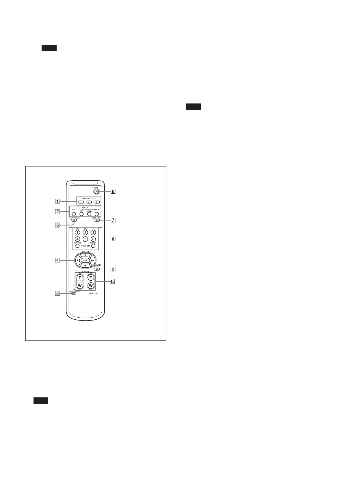
Remote Commander
2 FOCUS buttons
Used for focus adjustment.
Press the AUTO button to adjust the focus automatically.
To adjust the focus manually, press the MANUAL button,
and adjust it with the FAR and NEAR buttons.
3 DATA SCREEN button
Press this button to display the main menu. Press it again
to turn off the menu. If you press the button when a lowerlevel menu is selected, the display goes back to a higherlevel menu.
Note
Pan/tilt operations are disabled when the menu is
displayed.
4 PAN-TILT buttons
Press the arrow buttons to perform panning and tilting.
Press the HOME button to face the camera back to the
front.
When the menu is displayed, use V or v to select the menu
items and B or b to change the set values. The selected
setting menu is displayed, by pressing the HOME button
when the main menu is displayed.
5 L/R DIRECTION SET button
Hold down this button and press the REV button to change
the direction of the camera movement opposite to that
indicated by the arrow of the B/b buttons.
To reset the direction of the camera movement, press the
STD button while holding down this button.
1 CAMERA SELECT buttons
Press the button corresponding to the camera you want to
operate with the Remote Commander.
The camera number can be set using the IR SELECT switch
on the rear of the camera.
Note
If two or more cameras are adjacent and have the same
camera number, they are operated simultaneously with the
same Remote Commander. When you install the cameras
close to each other, set different camera numbers.
For the camera number setting, see “Operating Multiple
Cameras with the Remote Commander” described in the
Operating Instructions supplied with the camera.
6 POWER switch
Press this button to turn on/off the camera when the
camera is connected to an AC outlet.
7 BACK LIGHT button
Press this button to enable the backlight compensation.
Press it again to disable the backlight compensation.
8 POSITION buttons
Hold down the PRESET button and press button 1 to 6 to
store the current camera direction, zooming, focus
adjustment and backlight compensation in the memory of
the pressed number button.
To erase the memory contents, hold down the RESET
button and press button 1 to 6.
9 PAN-TILT RESET button
Press this button to reset the pan/tilt position.
0 ZOOM buttons
Use the SLOW button to zoom slowly, and the FAST
button to zoom quickly.
Press the T (telephoto) side of the button to zoom in, and
the W (wide angle) side to zoom out
7

Basic Functions
Basic Functions
Zoom
The camera employs an 10× optical zoom lens
combined with a digital zoom function allowing you to
zoom up to 40×.
Lens specifications: Optical 10×, f = 3.4 to 33.9 mm
(F1.8 to F2.1)
The horizontal angle of view is approximately 70
degrees (wide end) to 8 degrees (tele end).
Digital Zoom enlarges the center of the subject by
expanding each image in both the vertical and
horizontal directions. When 4× digital zoom is used,
the number of effective picture elements in each
direction reduces to
deteriorates.
You can activate the zoom in the following two ways:
•By pressing the T (tele) or W (wide) buttons on the
Remote Commander.
•Using a VISCA Command
Using Standard Mode
Using Variable Mode
There are eight levels of zoom speed.
Direct Mode
Setting the zoom position enables quick
movement to the designated position.
1
/4 and the overall resolution
Focus
Focus has the following modes, all of which can be set
using VISCA Commands.
• Auto Focus Mode
The minimum focus distance is 100 mm at the optical
wide end (extreme close-up settings with VISCA
control) (distance from the front end of the lens).
• Manual Focus Mode
MF (Manual Focus) has both a Standard Speed Mode
and a Variable Speed Mode. Standard Speed Mode
focuses at a fixed rate of speed. Variable Speed Mode
has eight speed levels that can be set using a VISCA
Command.
To stop the required operation after sending a
Standard Speed command or a Variable Speed
command, send the Stop command.
• One Push Trigger Mode
When a Trigger Command is received, the lens
moves to adjust the focus for the subject. The focus
lens then holds the same position until the next
Trigger Command is input.
• Infinity Mode
The lens is forcibly moved to a position suitable for
an unlimited distance.
• Near Limit Mode
Can be set in a range from about 3 m (2000) to 10 cm
(7600).
The focus range is narrowed by excluding the
unnecessary range.
8

Basic Functions
White Balance
White Balance has the following modes, all of which
can be set using VISCA Commands.
• Auto White Balance
This mode computes the white balance value output
using color information from the entire screen. It
outputs the proper value using the color temperature
radiating from a black subject based on a range of
values from 3000 to 7500K.
This mode is the default setting.
• Indoor
3200 K Base Mode
• Outdoor
5800 K Base Mode
• One Push WB
The One Push White Balance mode is a fixed white
balance mode that may be automatically readjusted
only at the request of the user (One Push Trigger),
assuming that a white subject, in correct lighting
1
conditions and occupying more than
/2 of the image,
is submitted to the camera.
One Push White Balance data is lost when the power
is turned off. If the power is turned off, reset the One
Push White Balance.
• Manual WB
Manual control of R and B gain, 256 steps each
Automatic Exposure Mode
The variety of AE functions, which allow video signal
to output the optimum image for subjects from low
light conditions to bright light conditions, are
available.
• Full Auto
Auto Iris and Gain, Fixed Shutter Speed (59.94/
29.97/NTSC:
• Slow shutter limit
Lower limit of the slow shutter mode in the Full Auto
mode. For the 59.94/29.97/NTSC video format, select
the lower limit from among 1/60, 1/30 or 1/15.
For the 50/25/PAL video format, select the lower
limit from among 1/50, 1/25 or 1/12.
• Shutter Priority
Variable Shutter Speed, Auto Iris and Gain
1
(
/2 to 1/10,000 s, 21 steps, high speed shutter: 15 steps,
slow shutter: 6 steps)
• Iris Priority
Variable Iris (F1.8 to Close, 18 steps), Auto Gain and
Shutter speed.
1
/60 s, 50/25/PAL: 1/50 s)
1)
• Manual
Variable Shutter, Iris and Gain.
• Bright
Variable Iris and Gain (Close to F1.8, 18 steps at
0 dB: F1.8, 6 steps from 0 to 18 dB)
• Spot light
Avoids a situation where the face of the subject is
over-illuminated, and becomes whitish.
AE – Shutter Priority
The shutter speed can be set freely by the user to a
total of 21 steps – 15 high speeds and 6 low speeds.
1
When the slow shutter is set, the speed can be
1
/15, 1/8, or 1/4 s. The picture output is read at a normal
/30,
rate from the memory. The memory is updated at a low
rate from the CCD. AF capability is low.
In high speed mode, the shutter speed can be set up to
1
/10,000 s. The iris and gain are set automatically,
according to the brightness of the subject.
Parameter 59.94i 50i
[sec] [sec]
15 1/10000 1/10000
14 1/6000 1/6000
13 1/4000 1/3500
12 1/3000 1/2500
11 1/2000 1/1750
10 1/1500 1/1250
0F 1/1000 1/1000
0E 1/725 1/600
0D 1/500 1/425
0C 1/350 1/300
0B 1/250 1/215
0A 1/180 1/150
09 1/125 1/120
08 1/100 1/100
07 1/90 1/75
06 1/60 1/50
05 1/30 1/25
04 1/15 1/12
03 1/8 1/6
02 1/4 1/3
01 1/2 1/2
Note
When the low shutter speed is used, Auto Focus and
White Balance may not function fully.
.................................................................................................................................................................................................................................
1) Flicker can be eliminated by setting shutter to:
t1/100 s for NTSC models used in countries with a 50 Hz power supply
frequency.
t1/120 s for PAL models used in countries with a 60 Hz power supply
frequency.
9
Basic Functions
AE – Iris Priority
The iris can be set freely by the user to 18 steps
between F1.8 and Close.
The gain and shutter speed are set automatically
according to the brightness of the subject.
parameter IRIS (F1.8) F No. parameter IRIS (F1.8) F No
11 F1.8 08 F8.0
10 F2.0 07 F9.6
0F F2.4 06 F11
0E F2.8 05 F14
0D F3.4 04 F16
0C F4.0 03 F19
0B F4.8 02 F22
0A F5.6 01 F26
09 F6.8 00 CLOSE
AE – Manual
The shutter speed (21 steps), iris (18 steps) and gain (8
steps) can be set freely by the user.
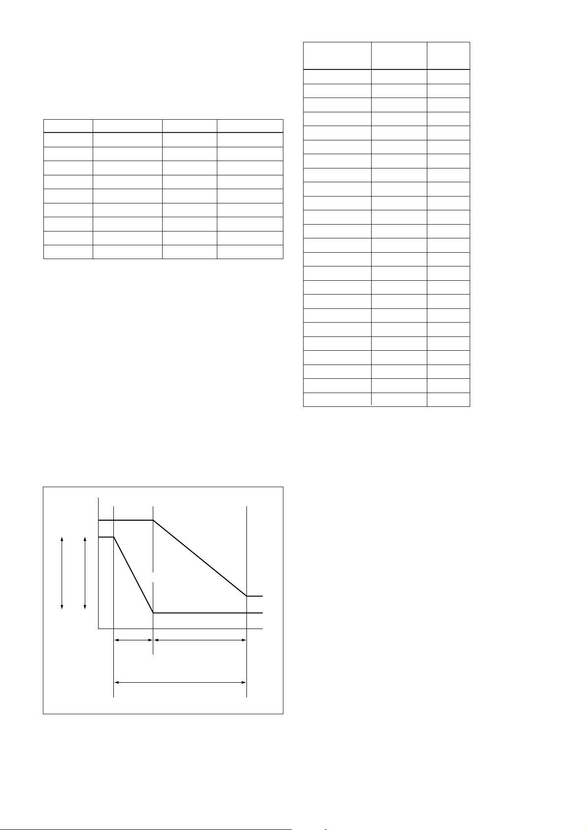
AE – Bright
The bright control function adjusts both the gain and
iris using an internal algorithm according to a
brightness level freely set by the user. Exposure is
controlled by gain when dark and by iris when bright.
As both gain and iris are fixed, this mode is used when
exposing at a fixed camera sensitivity. When switching
from Full Auto or Shutter Priority Mode to Bright
Mode, the current status will be retained for a short
period of time.
Only when the AE mode is set to “Full Auto” or
“Shutter Priority,” the user can switch it to “Bright.”
Parameter IRIS (F1.8) GAIN
F No.
17 F1.8 18dB
16 F1.8 15dB
15 F1.8 12dB
14 F1.8 9dB
13 F1.8 6dB
12 F1.8 3dB
11 F1.8 0dB
10 F2.0 0dB
0F F2.4 0dB
0E F2.8 0dB
0D F3.4 0dB
0C F4.0 0dB
0B F4.8 0dB
0A F5.6 0dB
09 F6.8 0dB
08 F8.0 0dB
07 F9.6 0dB
06 F11 0dB
05 F14 0dB
04 F16 0dB
03 F19 0dB
02 F22 0dB
01 F26 0dB
00 CLOSE 0dB
When switching from the Shutter Priority mode to the
Bright mode, the shutter speed set in the Shutter
Priority mode is maintained.
IRIS
OPEN
CLOSE
Gain
AGC
MAX
IRIS gain curve
AGC gain curve
MIN
Dark Bright
Controlled
by gain
Bright limit controllable
for this unit
Controlled by IRIS
10

Basic Functions
Exposure Compensation
Exposure compensation is a function which offsets the
internal reference brightness level used in the AE
mode by steps of 1.5 dB.
EXPOSURE Comp Step
Value
0E +10.5dB +7
0D +9dB +6
0C +7.5dB +5
0B +6dB +4
0A +4.5dB +3
09 +3dB +2
08 +1.5dB +1
07 0dB 0
06 –1.5dB –1
05 –3dB –2
04 –4.5dB –3
03 –6dB –4
02 –7.5dB –5
01 –9dB –6
00 –10.5dB –7
Effect
It consists of the following functions.
• Neg. Art: Negative/Positive Reversal
• Black White: Monochrome Image
Checking the Location of the Camera for
Signals from the IR Remote Commander
The supplied Remote Commander may not work
correctly near inverter lighting fixtures. In such a case,
the camera is probably installed in a place where it
cannot detect the infrared signals from the Remote
Commander.
While the camera is being initialized after the power is
turned on by connecting the camera to an AC outlet
using the AC power adaptor and AC power cord, or by
using a VISCA command, the camera detects whether
or not the camera is able to receive infrared signals
from the Remote Commander. You can check the
result of this operation via the IR_ConditionInq
command (see page 30).
When the installation location does not allow stable
reception, try to install the camera farther away from
the inverter lighting fixtures.
Aperture Control
Aperture control is a function which adjusts the
enhancement of the edges of objects in the picture.
There are 16 levels of adjustment, starting from “no
enhancement.” When shooting text, this control may
help by making the text sharper.
Back Light Compensation
When the background of the subject is too bright, or
when the subject is too dark due to shooting in the AE
mode, back light compensation will make the subject
appear clearer.
Camera ID
The ID can be set up to 65,536 (0000 to FFFF). As this
will be memorized in the nonvolatile memory inside
the camera, data will be saved, regardless of the
“position preset.”
Others
Power On/Off
Powers the camera on and off. When the power is off,
the camera is able to accept only the lowest level of
VISCA Commands and POWER of the Remote
Commander; the display and other features are turned
off.
I/F clear
Clears the Command buffer of the camera. Clearing
the buffer can also be carried out from the control
application software when the power is on.
Address set
VISCA is a protocol, which normally can support a
daisy chain of up to seven attached devices.
Therefore, whenever a camera is connected for the first
time, be sure to use the address set to confirm the
address.
11

Memory (Position Preset)
Using the position preset function, 6 sets of camera
shooting conditions can be stored and recalled.
This function allows you to achieve the desired status
instantly even without adjusting the following items
each time:
• Pan-Tilt position
• Zoom Position
• Focus Auto/Manual
• Focus Position
• AE Mode
• Shutter control parameters
• Bright Control
• Iris control parameters
• Gain control parameters
• Exposure Compensation On/Off
• Exposure Level
• Backlight Compensation On/Off
• White Balance Mode
• R/B Gain
• Aperture
Basic Functions
The settings are recalled when the power is turned on.
For setting items, see the “Initial Settings, Position Preset”
section on page 13.
Note
When you turn the camera to the right or left beyond
the 45° with the camera pointed downward by 25°, the
camera may be caught on the lens, depending on the
zoom position of the lens.
12
 Loading...