


EX780SP
Table of contents
 Loading...
2001 Sony Corporation
Color Camera Module
FCB-EX780S/EX780SP
A-B16-100-12 (1)
Technical Manual

2
Table of Contents
Features ..................................................................... 3
Locations of Controls ............................................... 4
Basic Functions ......................................................... 5
Overview of Functions ................................................ 5
Eclipse ...................................................................... 12
Spectral Sensitivity Characteristics .......................... 12
Vibrational Specifications ......................................... 12
Initial Values, Custom Preset and Backup ................ 13
Mode Condition ........................................................ 15
Command List ......................................................... 18
VISCA/RS-232C Commands ................................... 18
FCB-EX780S/SP Commands................................... 24
Specifications .......................................................... 42
Precautions .............................................................. 45

3
Overview
Features
• The CCD features 680,000 effective picture elements
and an image stabilizer function for high-resolution
shooting.
•25× optical zoom.
• Supports external synchronization (V-lock).
• Adopts newly developed DSP for improved picture
quality when using the digital zoom or the slow
shutter.
• An infrared (IR) Cut-Filter can be disengaged from
the image path for increased sensitivity in low light
environments. The ICR will automatically engage
depending on the ambient light, allowing the camera
to be effective in day/night environment.
• VISCA is a communications protocol, which enables
the camera to be controlled remotely from a host
computer/controller.
• Six memory locations are provided to temporally
save and recall up to six sets of camera settings.
4
Locations of Controls
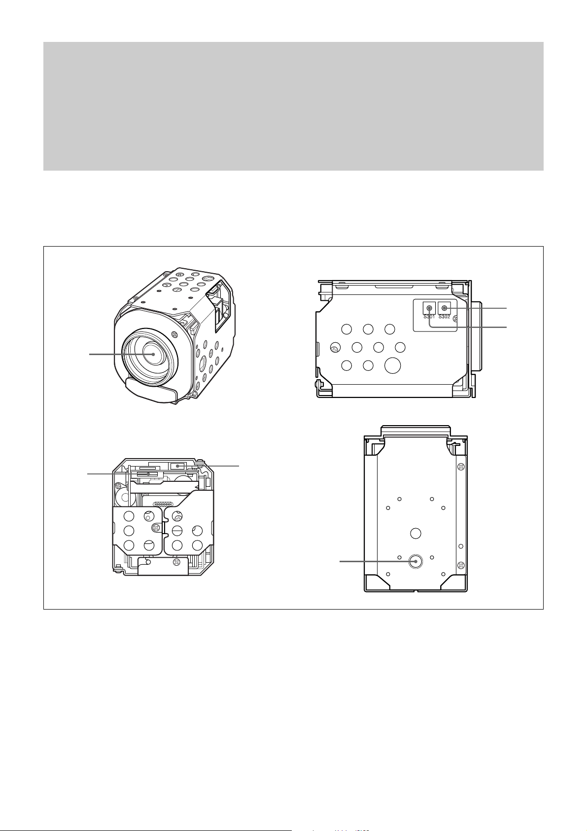
Locations of Controls
Main Unit
1 Lens
2 CN901 jack
3 CN902 jack
4 TELE button
5 WIDE button
6 Tripod screw holes
When a tripod is used, please use
10 mm (
13
/32 in.) screws to attach it
to the camera. Also, please be
sure to attach the tripod securely.
Front
Rear Bottom
1
2
3
4
5
6
Left side
5
Basic Functions
Basic Functions
Overview of Functions
VISCA commands are the basis of camera control.
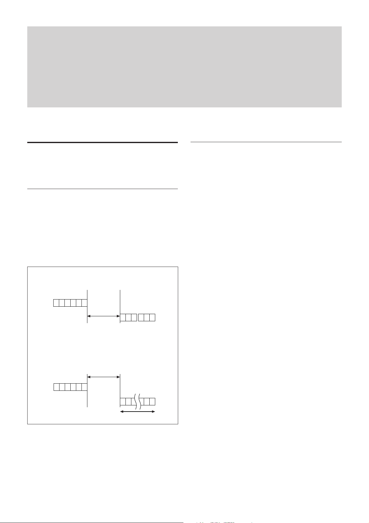
Timing Chart
As VISCA Command processing can only be carried
out one time in a Vertical cycle, it takes the maximum
1V cycle time for an ACK/Completion to be returned.
If the Command ACK/Completion communication
time can be cut shorter than the1V cycle time, then
every 1V cycle can receive a Command.
In general
• Power On/Off
Powers the camera on and off. When the power is off,
the camera is able to accept only the lowest level of
VISCA Commands; the display and other features are
turned off.
• I/F clear
Clears the Command buffer of the EX780S/SP.
Clearing the buffer can also be carried out from the
control application software when the power is on.
• Address set
VISCA is a protocol, which normally can support a
daisy chain of up to seven attached devices.
However, the FCB-EX780S does not support
connection of cameras in a daisy chain. Therefore,
whenever a camera is connected for the first time, be
sure to use the address set to confirm the address.
The EX780S does not support connection of cameras
in a daisy chain. However, whenever a camera is
connected for the first time, be sure to use the address
set to confirm the address.
• ID Write
Sets the camera ID.
• Mute
Blanks the screen and sends out a synchronizing
signal.
• Lens Initialize
Initializes the zoom and focus of the lens. Even when
power is already on, it initializes the zoom and the
focus.
• Comp Scan
A pixel blemish-masking feature, which can be made
to reevaluate overall CCD pixel blemishes and mask
severely flawed pixels automatically upon receiving
the COMP SCAN command. This feature helps to
mask the flaws found in CCD imagers, even after the
camera has been powered on for some time.
Query Commands
Command
16.7 msec (20 msec*PAL)
RxD
TxD
ACK Completion
16.7 msec (20 msec*PAL)
RxD
TxD
Completion
Command
General Commands
16 Byte
Within
Within

6
Basic Functions
Zoom
The EX780S/SP employs a 25× optical zoom lens
combined with a digital zoom function; this camera
allows you to zoom up to 300x.
• Optical 25×, f = 2.4 to 60 mm (F 1.6 to F 2.7)
The horizontal angle of view is approximately 45
degrees (wide end) to 2.0 degrees (tele end).
Digital Zoom enlarges the center of the subject by
expanding each image in both the vertical and
horizontal directions. When 300× zoom is used, the
number of effective picture elements in each direction
reduces to
1
/12 and the overall resolution deteriorates.
You can activate the zoom in the following two ways
• By pressing the TELE or WIDE buttons on the
camera itself
• Using a VISCA Command
Using Standard Mode
Using Variable Mode
There are eight levels of zoom speed.
Direct Mode
Setting the zoom position enables quick
movement to the designated position.
Digital Zoom ON/OFF
In these standard and variable Speed Modes, it is necessary
to send Stop Command to stop the zoom operation.
• The Zoom Mode supports a Combined Mode and a
Separate Mode.
Combined Mode
This is the previously existing zoom method.
After the optical zoom has reached its maximum
level, the camera switches to Digital Zoom Mode.
Separate Mode
In this mode, Optical Zoom and Digital Zoom can
be operated separately. You can use digital zoom
magnification at any time from within any level of
optical magnification.
Focus
Focus has the following modes, all of which can be set
using VISCA Commands.
• Auto Focus Mode
The minimum focus distance is 35 mm at the optical
wide end and 800 mm at the optical tele end, and is
independent of the digital zoom.
The AutoFocus (AF) function automatically adjusts
the focus position to maximise the high frequency
content of the picture in a center measurement area,
taking into consideration the high luminance and
strong contrast components.
- Normal AF Mode
This is the normal mode for AF operations.
- Interval AF Mode
The mode used for AF movements carried out at
particular intervals. The time intervals for AF
movements and for the timing of the stops can be
set in one-second increments using the Set Time
Command. The initial value for both is set to five
seconds.
- Zoom Trigger Mode
When the zoom is changed with the TELE or the
WIDE buttons, the pre-set value (initially set at 5
seconds) becomes that for AF Mode. Then, it
stops.
AF sensitivity can be set to either HIGH or LOW.
- HIGH
Reaches the highest focus speed quickly. Use this
when shooting a subject that moves frequently.
Usually, this is the most appropriate mode.
- LOW
Improves the stability of the focus. When the
lighting level is low, the AF function does not take
effect, even though the brightness varies,
contributing to a stable image.
When used for 24 hours continuously, initialization
of lens system once a day is recommended because
this will make the life of lens longer. The Initialize
Lens Command takes a little less than 3 seconds to
initialize the focus and zoom.
• Manual Focus Mode
Manual Focus has both a Standard Speed Mode and a
Variable Speed Mode. Standard Speed Mode focuses
at a fixed rate of speed. Variable Speed Mode has
eight speed levels that can be set using a VISCA
Command.
• One Push Trigger Mode
When a Trigger Command is sent, the lens moves to
adjust the focus for the subject. The focus lens then
holds that position until the next Trigger Command is
input.
• Infinity Mode
The lens is forcibly moved to a position suitable for
an unlimited distance.
• Near Limit Mode
Can be set in a range from 1000 (∞) to C000 (35 mm).

7
Basic Functions
White Balance
White Balance has the following modes, all of which
can be set using VISCA Commands.
• Auto White Balance
This mode computes the white balance value output
using color information from the entire screen. It
outputs the proper value using the color temperature
radiating from a black subject based on a range of
values from 3000 to 7500K.
This mode is the factory setting.
• ATW
Auto Tracing White balance (2000 to 10000 K)
• Indoor
3200 K Base Mode
• Outdoor
5800 K Base Mode
• One Push WB
The One Push White Balance mode is a fixed white
balance mode that may be automatically readjusted
only at the request of the user (One Push Trigger),
assuming that a white subject, in correct lighting
conditions, and occupying more than 1/2 of the
image, is submitted to the camera.
One Push White Balance data is lost when the power
is turned off. If the power is turned off, reset One
Push White Balance.
• Manual WB
Manual control of R and B gain, 256 steps each
Automatic Exposure Mode
The variety of AE functions, which allow video signal
to output the optimum image for subjects from low
light condition, to high light conditions, it is available.
• Full Auto
Auto Iris and Gain, Fixed Shutter Speed (NTSC: 1/60
sec., PAL: 1/50 sec.)
• Shutter Priority
1)
Variable Shutter Speed, Auto Iris and Gain
(1/1 to 1/10,000 sec., 22 steps, std. shutter: 16 steps,
slow shutter: 6 steps)
1)Flicker can be eliminated by setting shutter to
t1/100s for NTSC models used in countries with a 50 Hz
power supply frequency
t1/120s for PAL models used in countries with a 60 Hz
power supply frequency
• Iris Priority
Variable Iris (F1.6 to Close, 18 steps), Auto Gain and
Shutter speed
• Manual
Variable Shutter, Iris and Gain
• Bright
Variable Iris and Gain (Close to F1.6, 17 steps at
0 dB: F1.6, 15 steps from 0 to 28 dB)
AE – Shutter priority
The shutter speed can be set freely by the user to a
total of 22 steps – 16 high speeds and 6 low speeds.
When the slow shutter is set, the speed can be
1
/30s,
1
/15s,
1
/8s,
1
/4s,
1
/2s,
1
/1s. The picture output is read at a
normal rate from the memory. The memory is updated
at a low rate from the CCD. AF capability is low.
In high speed mode, the shutter speed can be set up to
1/10,000s. The iris and gain are set automatically,
according to the brightness of the subject.
Data NTSC PAL
15 10000 10000
14 6000 6000
13 4000 3500
12 3000 2500
11 2000 1750
10 1500 1250
0F 1000 1000
0E 725 600
0D 500 425
0C 350 300
0B 250 215
0A 180 150
09 125 120
08 100 100
07 90 75
06 60 50
05 30 25
04 15 12
03 8 6
02 4 3
01 2 2
00 1 1
AE – Iris priority
The iris can be set freely by the user to 18 steps
between F1.6 and Close.
The gain and shutter speed are set automatically,
according to the brightness of the subject.
Data
Setting value
Data
Setting value
11 F1.6 08 F8
10 F2 07 F9.6
0F F2.4 06 F11
0E F2.8 05 F14
0D F3.4 04 F16
0C F4 03 F19
0B F4.8 02 F22
0A F5.6 01 F28
09 F6.8 00 CLOSE
8
Basic Functions
AE – Manual
The shutter speed (22 steps), iris (18 steps) and gain
(16 steps) can be set freely by the user.
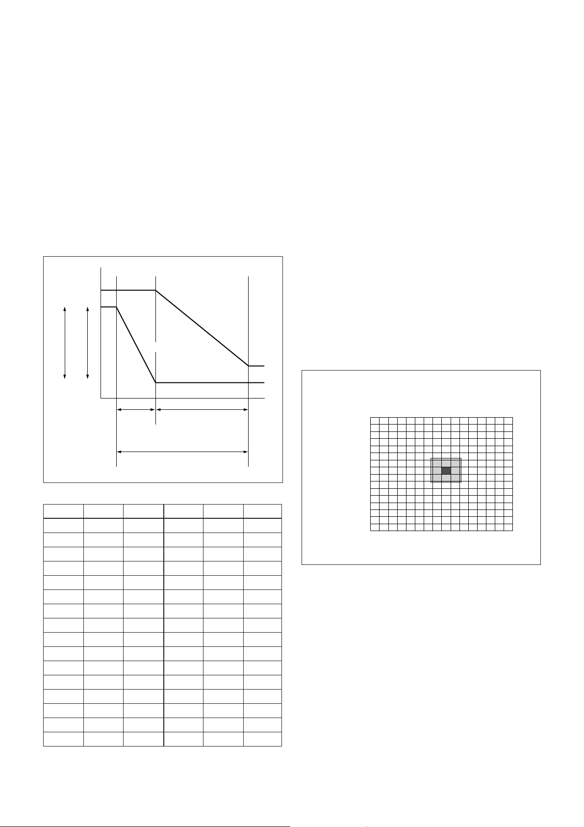
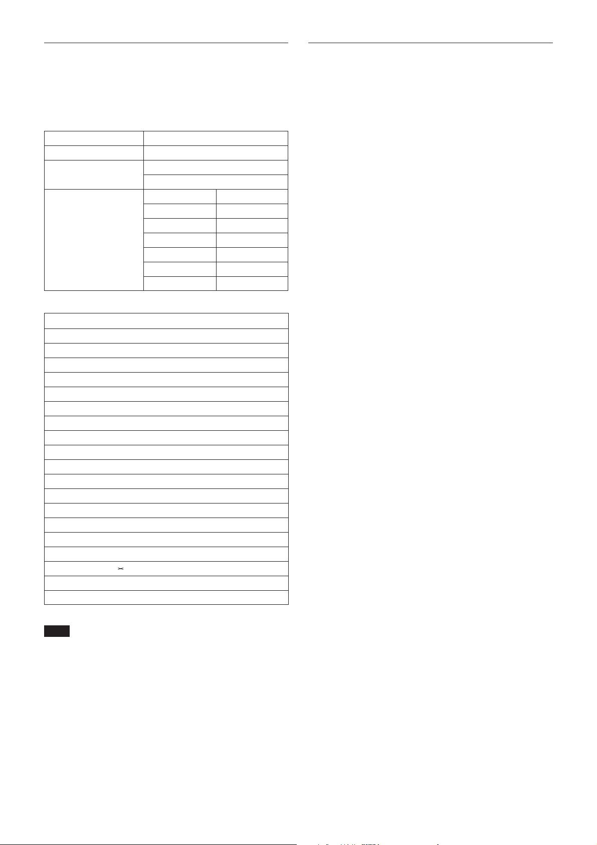
AE – Bright
The bright control function adjusts both gain and iris
using an internal algorithm, according to a brightness
level freely set by the user. Exposure is controlled by
gain when dark, and by iris when bright.
As both gain and iris are fixed, this mode is used when
exposing at a fixed camera sensitivity. When switching
from Full Auto or Shutter Priority Mode to Bright
Mode, the current status will be retained for a short
period of time.
Only when the AE mode is set to “Full Auto” or
“Shutter Priority,” can you switch it to “Bright.”
MIN
MAX
AGC
CLOSE
OPEN
IRIS
Gain
Dark Bright
IRIS curve
Gain curve
Controlled
by gain
Controlled by IRIS
Bright limit which controllable
for this unit
Data Iris Gain Data Iris Gain
1F F1.6 28 dB 0F F2.4 0 dB
1E F1.6 26 dB 0E F2.8 0 dB
1D F1.6 24 dB 0D F3.4 0 dB
1C F1.6 22 dB 0C F4 0 dB
1B F1.6 20 dB 0B F4.8 0 dB
1A F1.6 18 dB 0A F5.6 0 dB
19 F1.6 16 dB 09 F6.8 0 dB
18 F1.6 14 dB 08 F8 0 dB
17 F1.6 12 dB 07 F9.6 0 dB
16 F1.6 10 dB 06 F11 0 dB
15 F1.6 8 dB 05 F14 0 dB
14 F1.6 6 dB 04 F16 0 dB
13 F1.6 4 dB 03 F19 0 dB
12 F1.6 2 dB 02 F22 0 dB
11 F1.6 0 dB 01 F28 0 dB
10 F2 0 dB 00 CLOSE 0 dB
When switching from the Shutter Priority mode to the
Bright mode, the shutter speed set in the Shutter
Priority mode is maintained.
Spot Exposure Mode
In Full Auto AE, the level for the entire screen is
computed and the optimum Auto Iris and Gain levels
are determined. In Spot AE, a particular section of the
subject can be designated, and then that portion of the
image can be weighted and a value computed so that
Iris and Gain can be optimized to obtain an image.
For example, in an image with a lot of movement and
with varying levels of brightness, portions without
much change can be designated as such a “spot,” and
changes to the screen can be minimized in that area.
As shown in the diagram below, a range of 16 blocks
vertically and 16 blocks horizontally can be
designated.
In the case where the center is designated (shown in
black), the level is computed along with a weighted
value for the surrounding block (shaded), including the
specified portions; and then the Gain and Iris are set.
The value of the designated portions and the
surrounding areas should be calculated as 90%, the rest
should be set to 10%.
Horizontal 16
Vertical 16
0
0
1
2
3
4
5
6
7
8
9
A
B
C
D
E
F
123456789ABCDEF
9
Basic Functions
Exposure Compensation
Exposure compensation is a function which offsets the
internal reference brightness level used in the AE
mode, by steps of 1.5 dB.
Data Step
Setting value
0E 7 10.5 dB
0D 6 9 dB
0C 5 7.5 dB
0B 4 6 dB
0A 3 4.5 dB
09 2 3 dB
08 1 1.5 dB
07 0 0 dB
06 –1 –1.5 dB
05 –2 –3 dB
04 –3 –4.5 dB
03 –4 –6 dB
02 –5 –7.5 dB
01 –6 –9 dB
00 –7 –10.5 dB
Aperture Control
Aperture control is a function which adjusts the
enhancement of the edges of objects in the picture.
There are 16 levels of adjustment, starting from “no
enhancement.” When shooting text, this control may
help by making them sharper.
Back Light Compensation
When the background of the subject is too bright, or
when the subject is too dark due to shooting in the AE
mode, back light compensation will make the subject
appear clearer.
Slow shutter – Auto/Manual
When set to “Auto,” ensures that the slow shutter is set
automatically when the brightness drops. Effective
only when the AE mode is set to “Full Auto.”
Set to “Slow Shutter Manual” at shipment.
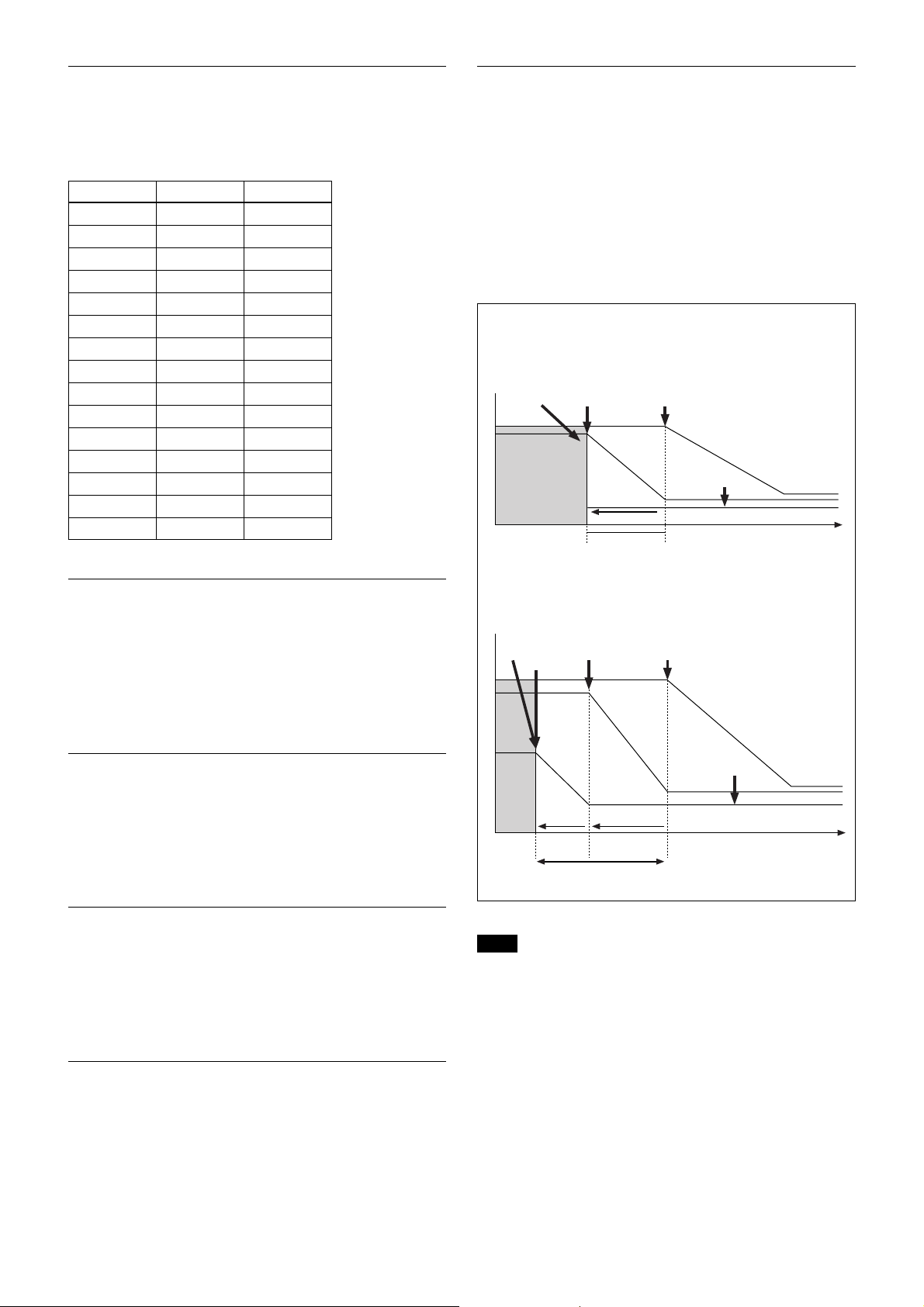
ICR (IR Cut-Removable) Mode
An infrared (IR) Cut-Filter can be disengaged from the
image path for increased sensitivity in low light
environments. The ICR will automatically engage
depending on the ambient light, allowing the camera to
be effective in day/night environments.
When Auto Slow Shutter is ON
ICR
SHUTTER
Dark Bright
Adjustable
AGC
MAX
IRIS
OPEN
Shutter 1/60 sec
AdjustableICR OFF t ON
GAIN
ICR ON
IRIS
Dark
ICR AGC
MAX
GAIN
MAX
IRIS
IRIS
ICR
ON
OPEN
SHUTTER
Slow
Shutter
ON
Bright
Adjustable
Slow
Shutter
Adjustable
AdjustableICR OFF t ON
When Auto Slow Shutter is OFF (initial setting)
Auto ICR Mode
Auto ICR Mode automatically switches the settings
needed for attaching or removing the IR Cut Filter.
With a set level of darkness, the IR Cut Filter is
automatically disabled (ICR ON), and the infrared
sensitivity is increased. With a set level of brightness,
the IR Cut Filter is automatically enabled (ICR OFF).
Also, on systems equipped with an IR light, the
internal data of the camera is used to make the proper
decisions to avoid malfunctions.
Note
When in Auto_ICR_OFF state and WB data is added (default), a
malfunction may occur when the subjects largely consisting of blue
and red colors are taken.

10
Basic Functions
Camera ID
The ID can be set up to 65,536 (0000 to FFFF). As this
will be memorized in the nonvolatile memory inside,
data will be saved regardless of whether it has been
backed up.
Effect
It consists of the following functions.
• Neg. Art: Negative/Positive Reversal
• Black White: Monochrome Image
Others
Mirror image
The video output from the camera can be reversed left
and right using this function.
Freeze
This function captures an image in the field memory of
the camera so that this image can be output
continuously.
Because communication inside the camera is based on V
cycle, the captured image is always the one 3V to 4Vs after
the sending of a Command. Thus, you can not specify a time
period after sending EVEN, ODD or a Command.
The Image Stabilizer Function
When the Image Stabilizer Function is ON, it helps in
obtaining a stable image free of vibration caused by
jarring movements. For a vibration frequency of
around 10 Hz, correction is approximately 90%.
Note
Be advised that, when using systems equipped with Pan and Tilt
functions, quick starts and stops are corrected for, causing a
different movement from that of the normal image.
Memory (Position preset)
Using the position preset function, 6 sets of camera
shooting conditions can be stored and recalled.
This function allows you to achieve the desired status
instantly, even without adjusting the following items
each time.
• Zoom Position
• Digital Zoom On/Off
• Focus Auto/Manual
• Focus Position
• AE Mode
• Shutter control parameters
• Bright Control
• Iris control parameters
• Gain control parameters
• Exposure Compensation On/Off
• Exposure Level
• Backlight Compensation On/Off
• Slow Shutter Auto/Manual
• White Balance Mode
• R/B Gain
• Aperture
• ICR Shoot On/Off
Custom Preset
As with the positon preset function, the camera
shooting conditions can be stored and recalled. The
settings are recalled when the power is turned on. For
setting items, refer to the “Initial Settings, Custom
Preset and Backup” section on page 13.
Privacy Zone Settings
For subjects requiring special treatment due to privacy
issues, designated areas of the image can be masked
from view.
In this situation, an area can be masked using Privacy
Zone settings. As shown in the diagram below, 12
blocks vertically and 16 horizontally, in a maximum of
6 places, can be masked.
• An example of a Command setting
Using 1 Command for a set: 81 01 04 76 00 02 01 05
02 0D 07 03 05 FF
0
1
2
3
4
5
6
7
8
9
A
B
A
B
0123456789ABCDEF
11
Basic Functions
Title Display
The camera can be given a title containing up to 20
characters such as “ENTRANCE” or “LOBBY”. The
position of the first character (horizontal, vertical) of
the title, blinking state, and color can also be changed.
Note
Cannot be displayed together with Privacy display.
Vposition 00 to 0A
Hposition 00 to 17
Blink
00: Does not blink
01: Blinks
00 White
01 Yellow
02 Violet
Color 03 Red
04 Cyan
05 Green
06 Blue
00 01 02 03 04 05 06 07
AB CDE F G H
08 09 0a 0b 0c 0d 0e 0f
IJKLMNOP
10 11 12 13 14 15 16 17
QR S TUVWX
18 19 1a 1b 1c 1d 1e 1f
YZ& ? ! 1 2
20 21 22 23 24 25 26 27
34 5678 9 0
28 29 2a 2b 2c 2d 2e 2f
ÀÈ Ì ÒÙÁ É Í
30 31 32 33 34 35 36 37
ÓÚ ÂÊÔÆŒÃ
38 39 3a 3b 3c 3d 3e 3f
ÕÑ Ç ßÄÏ Ö Ü
40 41 42 43 44 45 46 47
Å$
F
¥ DM £ ¿¡
48 49 4a 4b 4c 4d 4e 4f
ø“ : ‘ ., /-
Synchronization methods
Internal and external synchronization are available;
VISCA Commands allow you to switch between them.
• Internal synchronization
An internal vibrator inside the camera generates a
synchronizing signal as a basic oscillator.
NTSC=28.636363MHz
PAL=28.375MHz
• External synchronization (V-Lock Synchronization)
When a TTL level V-Lock pulse is input, the camera
synchronizes to the input signal (V-lock
synchronization). The frequency of the input signal
synchronizes to within ±1Hz of the external
synchronization.
Also, V-Phase phase adjustment can be carried out to
within ±90 degrees due to the V-Lock phase
adjustment. In addition, 360 degree phase adjustment
is possible because you can switch between 0 degree
and 180 degree phases.
Because V-Lock synchronization is a simple synchronization
method, color signals like a VBS “GenLock” cannot be
synchronized.
12
Basic Functions
3
1
.
7
3
°
2
1
.
0
9
°
1
.
5
3
°
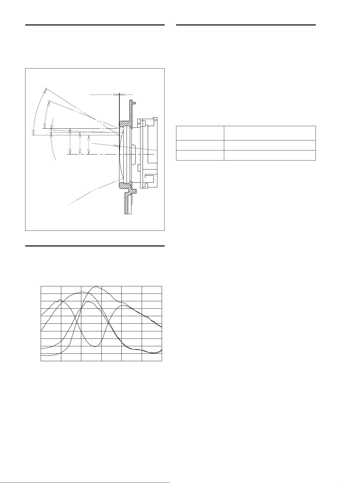
13.18
11.24
9.93
L=0.3
R41.27
Eclipse
When designing the housing, refer to the dimensional
allowance as shown in the figure below.
Spectral Sensitivity
Characteristics
Vibrational
Specifications
Test method (Random vibration)
• Fix the camera at the four fixation points of the base
using M2 screws.
• Perform the random vibration test under the
following conditions in the X, Y and Z directions for
20 minutes in each direction.
• The camera vibrational specification is to have no
malfunction after this test.
Power spectrum density
Effective overall value
Test time
5 to 50 Hz 4.14 m
2
/s
3
{0.043 G
2
/Hz}
50 to 100 Hz -36 dB/oct
14.3 m/s
2
{1.46 G}
20 minutes
Wave Length [nm]
Mg
G
Cy
Ye
400
0
0.1
0.2
0.3
0.4
0.5
0.6
0.7
0.8
0.9
1.0
450 500 550 600 650 700
Relative Response

13
Basic Functions
Initial Settings, Custom
Preset and Backup
Initial settings for the various functions of the FCB-
EX780S/EX780SP are indicated in the “Initial
settings” column.
The “Custom preset” column indicates whether the
custom preset function can be used to store the
settings. The function enables the stored settings to be
recalled automatically when the camera is turned on.
The “Standby backup” column indicates whether the
data is preserved even when the camera is powered
OFF.
Mode/Position setting Initial settings
Custom Back up
preset at standby
Zoom Position Wide end aa
D-Zoom On/Off On aa
D-Zoom Separate/Combine Combine aa
D-Zoom Position 00h aa
Focus Position — aa
Focus Auto/Manual Auto aa
Near Limit Setting 8000h (40cm) aa
AF Sensitivity Normal aa
AF Mode Normal aa
AF Run Time 5 sec aa
AF Interval 5 sec aa
WB Mode Auto aa
WB Data (Rgain, Bgain) — aa
One Push WB Data — aa
AE Mode Full Auto aa
Slow Shutter Mode Manual aa
Shutter Position 1/60sec (NTSC), 1/50sec (PAL) aa
Iris Position — aa
Gain Position — aa
Bright Position — aa
Exposure Compensation On/Off Off aa
Exposure Compensation Amount ±0 aa
BackLight On/Off Off aa
Spot AE On/Off Off aa
Spot AE Position Setting X=8, Y=8 aa
Aperture Level 5 aa
LR Reverse On/Off Off aa
Freeze On/Off Off ××
Picture Effect Off aa
ICR On/Off Off aa
Auto ICR On/Off Off aa
Stabilizer On/Off Off aa
Camera Memory Same as the initial value setting aa
Display On/Off Off aa
Mute On/Off Off ××
A circle “a” in this column signifies that the data is preserved.
A cross “×” signifies that the data IS NOT preserved.

14
Basic Functions
Mode/Position setting Initial settings
Custom Back up
preset at standby
Title Display On/Off Off aa
Title Setting — aa
Privacy Zone On/Off Off aa
Privacy Zone Setting — aa
Key Lock On/Off Off aa
Camera ID 0000h aa
External Lock Mode Internal aa
V-Phase Vsync edge position aa
V-Phase Phase Inversion No inversion aa
A circle “a” in this column signifies that the data is preserved.
A cross “×” signifies that the data IS NOT preserved.
Note
The number of times written to EEPROM (when Custom Preset is
executed) is limited.
Loading...