


A-E4U-100-11(1)
HD Color Video Camera
Technical Manual
EVI-H100S/H100V
2011 Sony Corporation
Table of Contents
Features............................................................................. |
3 |
Connection........................................................................ |
4 |
Locations of Controls........................................................ |
6 |
Basic Functions................................................................ |
10 |
Overview of Functions.................................................................. |
10 |
Initial Settings and Position Preset........................................... |
16 |
Mode Condition............................................................................... |
18 |
Command List.................................................................. |
23 |
VISCA RS-232C Commands......................................................... |
23 |
EVI-H100S/H100V Commands.................................................... |
31 |
D70 Mode......................................................................... |
47 |
Overview............................................................................................ |
47 |
Switching the Mode....................................................................... |
47 |
Accepting or Sending Back Commands................................. |
48 |
Translating Parameters................................................................. |
49 |
Specifications.................................................................. |
51 |
Precautions...................................................................... |
54 |

Features
The 1/2.8 type Exmor CMOS camera (utilising approximately 2 million valid pixels) allows for highdefinition shooting with superior picture quality.
The camera is equipped with a bright, F1.6 zoom lens with 20× optical zoom.
By adopting its wide and dynamic range functions, you can see the optimised shooting image which incorporates bright and dark subjects at the same time.
The camera has a variety of HD video format choices and digital and analogue interface connectors. The EVI-H100S camera has HD-SDI (High DefinitionSerial Digital Interface) output, suitable for longdistance transmission. The EVI-H100V camera has a DVI-I (VIDEO OUT) connector supporting both digital and analogue output.
The camera can be used for NTSC and PAL output in letter box size (EVI-H100S).
Adopts the industry standard RS-232C interface of VISCA camera protocol in external communication. It is possible to operate from long distances by using both RS-232C and RS-422.
You can install the camera on ceilings due to the functions of high-speed and wide range pan/tilt action and vertical image flip.
You can use the infrared remote commander to set the camera and also to select panning, tilting and zooming from the setting menu.
You can store up to 6 kinds of camera direction and camera status into the camera.
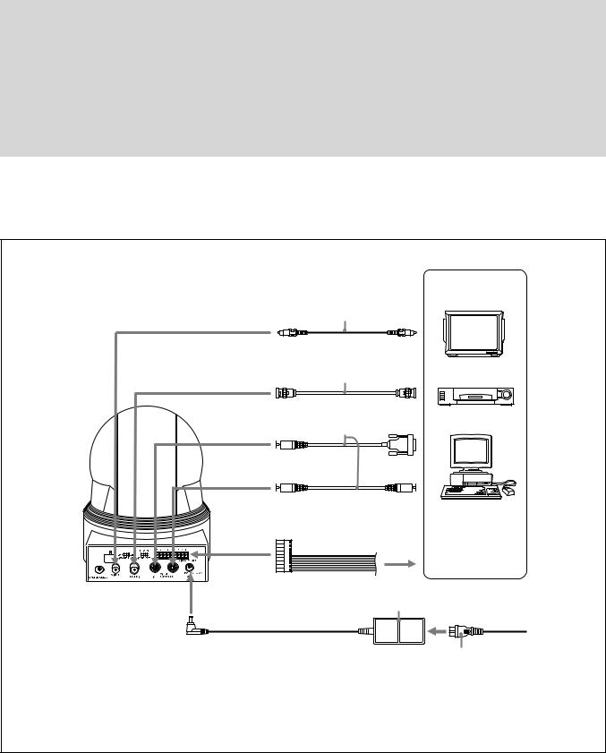
Connection
EVI-H100S
Video cable
(not supplied) to Video input
to VIDEO
Cable with BNC connector (not supplied)
to HD-SDI |
to HD-SDI input |
|
connector |
VISCA cable (not supplied) 1) |
|
to VISCA IN |
to RS-232C |
|
|
to VISCA OUT |
To VISCA IN of other |
|
EVI-H100S/H100V |
|
(when connecting |
|
to more than one |
|
camera) |
to VISCA RS-422 2)
Computer, video monitor, HD video monitor, VCR or HD CAM VTR with a video input jack, etc.
AC power adaptor (supplied)
to AC outlet
to DC 12V
Power cord (supplied)
1)When the camera is connected to a computer with a VISCA cable (cross type, RS-232C), you can operate the camera with the computer. To obtain a cable, consult the dealer where you bought your camera.
2)For details on how to connect using VISCA RS-422, see page 28.
(Continued)
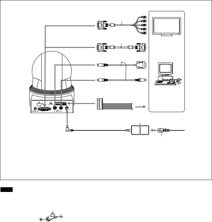
EVI-H100V
DVI to |
to component |
|
input |
||
component |
||
connector |
||
adapter cable |
||
(not supplied) |
|
|
to VIDEO OUT |
|
|
DVI cable |
|
|
(not supplied) |
|
to VIDEO OUT to DVI input connector VISCA cable (not supplied) 1)
to VISCA IN |
to RS-232C |
|
|
to VISCA OUT |
To VISCA IN of other |
|
EVI-H100S/H100V |
|
(when connecting |
|
to more than one |
|
camera) |
to VISCA RS-422 2)
Computer with serial communication interface, HD video monitor with DVI input interface, etc.
AC power adaptor (supplied)
to AC outlet
to DC 12V
Power cord (supplied)
1)When the camera is connected to a computer with a VISCA cable (cross type, RS-232C), you can operate the camera with the computer. To obtain a cable, consult the dealer where you bought your camera.
2)For details on how to connect using VISCA RS-422, see page 28.
Notes
Use only the AC power adaptor (JEITA type4) supplied with the unit. Do not use any other AC power adaptor.
Polarity of the plug
You have to set the video format of the signal to be output from the camera. For detailed information on how to set the video format, see “ SYSTEM SELECT switch” on page 7.
Do not make VISCA RS-232C and RS-422 connections at the same time, as this may cause malfunctions.

Locations of Controls
Main Unit
Front |
|
Rear |
|
|
|
|
|
|
|
|
|
||
|
|
|
|
|
|
|
|
|
|
|
|
|
|
|
|
|
|
|
|
|
|
|
|
|
|
|
|
|
|
|
|
|
|
|
|
|
|
|
|
|
|
|
|
|
|
|
|
|
|
|
|
|
|
|
|
EVI-H100S
Bottom
EVI-H100V
Lens
Remote sensorsPOWER lamp
STANDBY lamp
For detailed information on LED status of the POWER lamp and STANDBY lamp, see “LED Status” on page 46.
Remote sensors
(Continued)
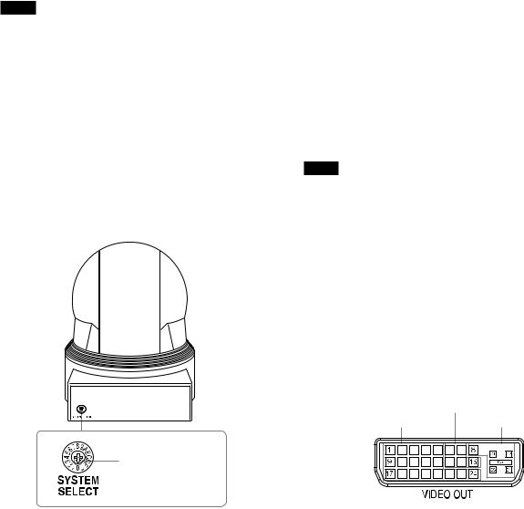
IMAGE FLIP switch
Flips the image upside down. Normally set this to OFF when you use the camera. When the camera is attached to the ceiling, set this to ON. Before you set the IMAGE FLIP switch, turn off the unit (or set to standby mode) and then, turn the power on by connecting the power adaptor, by VISCA control or the remote commander. When you switch this, the preset setting is returned to the initial setting.
IR SELECT switch
VISCA RS-422 connector
SYSTEM SELECT switch
This switch allows you to select the video format of the signal to be output from the VIDEO OUT connectors.
Notes
Be sure to set this switch before you turn on the power of the camera. You can also set this switch in the standby mode of the camera. After completing the setting, turn on the power of the camera by connecting it to an AC outlet using the supplied AC power adaptor and AC power cord, by using the VISCA command or remote commander.
Be sure to use a Phillips-head screwdriver when changing the switch position. If you use a tool other than the designated screwdriver, the crossed groove may be damaged.
This camera does not include a function that automatically selects video output signals based on the DVI monitor’s resolution. Be sure to configure settings based on the monitor manually. (EVI-H100V)
HDTV video signal outputs display without distortion on monitors with 16:9 aspect ratios.
Set this arrow to the desired video format.
Locations of Controls
Switch |
Video format |
EVI-H100S |
EVI-H100V |
|
|
position |
support |
support |
|
||
|
|
||||
|
|
|
|
|
|
0 |
1080i/ |
Yes |
Yes |
|
|
59.94 (29.97PsF) |
|
||||
|
|
|
|
||
1 |
1080p/29.97 |
Yes |
Yes |
59.94 Hz |
|
2 |
720p/59.94 |
Yes |
Yes |
system |
|
3 |
720p/29.97 |
Yes |
Yes |
|
|
4 |
NTSC (LB) |
Yes (SD OUT) |
No |
|
|
5 |
No output |
— |
— |
— |
|
6 |
No output |
— |
— |
— |
|
7 |
VISCA Control |
Yes |
Yes |
— |
|
8 |
1080i/50 (25PsF) |
Yes |
Yes |
|
|
9 |
720p/50 |
Yes |
Yes |
50 Hz |
|
A |
720p/25 |
Yes |
Yes |
||
system |
|||||
B |
1080i/50 |
Yes |
Yes |
||
|
|||||
C |
PAL (LB) |
Yes (SD OUT) |
No |
|
|
D |
No output |
— |
— |
— |
|
E |
No output |
— |
— |
— |
|
F |
No output |
— |
— |
— |
|
|
|
|
|
|
Yes: Outputs the image signal.
No: Does not output the image signal
LB: Abbreviation of LETTER BOX. A 4:3 aspect ratio video signal converted from 16:9 is output with a blank area (no signal, black) top and bottom to display the image on a 4:3 aspect ratio monitor without distortion.
Notes
If the switch position is set to “no output,” the POWER lamp and STANDBY lamp will both remain lit. In such cases, control via the remote commander and VISCA commands is disabled.
The VISCA CONTROL switch position allows you to configure the video format via external communication. Note that your configured video format will be activated only after restarting the camera. For details on the video output format settings command, see page 33.
SD OUT VIDEO connector
HD OUT HD-SDI connector (EVI-H100S), VIDEO OUT connector (EVI-H100V)
|
PLUG & PLAY |
TMDS |
ANALOG |

Pin No. |
Function |
1Data_2-
2Data_2+
3Shield (2, 4)
4No connection
5No connection
6No connection
7No connection
8Analog Vertical Sync
9Data_1-
10Data_1+
11Shield (1, 3)
12No connection
13No connection
14Power_+5 V
15GND
16Hot Plug
17Data_0-
18Data_0+
19Shield (0, 5)
20No connection
21No connection
22Shield Clock
23Clock+
24Clock-
C1 |
Analog Pr |
|
|
C2 |
Analog Y |
|
|
C3 |
Analog Pb |
|
|
C4 |
Analog Horizontal Sync |
|
|
C5 |
Analog GND |
VISCA IN connectorVISCA OUT connectorDC 12V connectorBOTTOM switches
12345
D70 mode switch
Set to ON to use the VISCA command for EVI-D70/ D70P.
IR OUT switch
Set to ON to enable output of the receiver signals, which are transmitted from the infrared remote commander via the VISCA IN connector (page 27), or set it to OFF
to disable the output.
Locations of Controls
RS-232C/RS-422 select switch
Set to ON to operate colour video camera using the VISCA command via the RS-422 interface. To change the mode, turn off the camera (not including standby mode) first, set the switch and then turn on the camera again. The mode cannot be switched while the camera is turned on.
Baud rate select switch
Set to ON for 38,400 bps or OFF for 9,600 bps. To change the mode, turn off the camera (not including standby mode) first, set the switch and then turn on the camera again. Mode switching is not possible while the camera is turned on.
Switch 5 (Not used)
Be sure to set this switch to OFF.
Tripod screw hole
Ceiling bracket mounting screw holes
Remote Commander
CAMERA SELECT buttons
Press the button corresponding to the camera you want to operate with the Remote Commander.
The camera number can be set using the IR SELECT switch on the rear of the camera.
Note
If two or more cameras are adjacent and have the same camera number, they are operated simultaneously with the same Remote Commander. When you install the cameras close to each other, set different camera numbers.
For the camera number setting, see “Operating Multiple Cameras with the Remote Commander” described in the Operating Instructions supplied with the camera.

Locations of Controls
FOCUS buttons
Used for focus adjustment.
Press the AUTO button to adjust the focus automatically. To adjust the focus manually, press the MANUAL button, and adjust it with the FAR and NEAR buttons.
DATA SCREEN button
Press this button to display the main menu. Press it again to turn off the menu. If you press the button when a lower-level menu is selected, the display goes back to a higher-level menu.
Note
Pan/tilt operations are disabled when the menu is displayed.
PAN-TILT buttons
Press the arrow buttons to perform panning and tilting. Press the HOME button to face the camera back to the front. When the menu is displayed, use or to select the menu items and or to change the set values. The selected setting menu is displayed, by pressing the HOME button when the main menu is displayed.
The Pan/tilt speed will slow down when the camera is zoomed, in order to allow precise positioning.
L/R DIRECTION SET button
Hold down this button and press the REV button to change the direction of the camera movement opposite to that indicated by the arrow of the / buttons.
To reset the direction of the camera movement, press the STD button while holding down this button.
POWER switch
Press this button to turn on/off the camera when the camera is connected to an AC outlet.
BACK LIGHT button
Press this button to enable the backlight compensation. Press it again to disable the backlight compensation.
POSITION buttons
Hold down the PRESET button and press button 1 to 6 to store the current camera direction, zooming, focus adjustment and backlight compensation in the memory of the pressed number button.
To erase the memory contents, hold down the RESET button and press button 1 to 6.
Note
These buttons do not function when the menu is displayed.
PAN-TILT RESET button
Press this button to reset the pan/tilt position.
ZOOM buttons
Use the SLOW button to zoom slowly, and the FAST button to zoom quickly.
Press the T (telephoto) side of the button to zoom in, and the W (wide angle) side to zoom out.

Basic Functions
Overview of Functions
Zoom
The camera employs a 20× optical zoom lens combined with a digital zoom function; this camera allows you to zoom up to 240×.
Optical 20×, f = 4.7 mm to 94.0 mm (F 1.6 to F 3.5)
The horizontal angle of view (1080i mode) is approximately 55.4 degrees (wide end) to 2.9 degrees (tele end).
Digital Zoom enlarges the center of the subject by expanding each image in both the vertical and horizontal directions. When 240× zoom is used, the number of effective picture elements in each direction reduces to 1/12 and the overall resolution deteriorates.
You can activate the zoom in the following ways with a VISCA command.
Using Standard Mode
Using Variable Mode
There are eight levels of zoom speed.
Direct Mode
Setting the zoom position enables quick movement to the designated position.
Digital Zoom ON/OFF
In these standard and variable Speed Modes, it is necessary to send Stop Command to stop the zoom operation.
Focus
Focus has the following modes, all of which can be set using VISCA Commands.
Auto Focus Mode
The minimum focus distance is 10 mm at the optical wide end and 800 mm at the optical tele end, and is independent of the digital zoom.
The Auto Focus (AF) function automatically adjusts the focus position to maximise the high frequency content of the picture in a center measurement area, taking into consideration the high luminance and strong contrast components.
- Normal AF Mode
This is the normal mode for AF operations.
- Interval AF Mode
The mode used for AF movements carried out at particular intervals. The time intervals for AF movements and for the timing of the stops can be set in one-second increments using the Set Time Command. The initial value for both is set to five seconds.
- Zoom Trigger Mode
When the zoom is changed, the pre-set value (initially set at 5 seconds) becomes that for AF Mode. Then, it stops.
AF sensitivity can be set to either Normal or LOW.
- Normal
Reaches the highest focus speed quickly. Use this when shooting a subject that moves frequently. Usually, this is the most appropriate mode.
- LOW
Improves the stability of the focus. When the lighting level is low, the AF function does not take effect, even though the brightness varies, contributing to a stable image.
Manual Focus Mode
Manual Focus has both a Standard Speed Mode and a Variable Speed Mode. Standard Speed Mode focuses at a fixed rate of speed. Variable Speed Mode has eight speed levels that can be set using a VISCA Command.
10
In these standard and variable Speed Modes, it is necessary to send Stop Command to stop the zoom operation.
One Push Trigger Mode
When a Trigger Command is sent, the lens moves to adjust the focus for the subject. The focus lens then holds that position until the next Trigger Command is input.
Infinity Mode
The lens is forcibly moved to a position suitable for an unlimited distance.
Near Limit Mode
Can be set in a range from 1000 (∞) to F000 (10 mm).
Default setting: D000h (30 cm)
White Balance
White Balance has the following modes, all of which can be set using VISCA Commands.
Auto White Balance
This mode computes the white balance value output using color information from the entire screen. It outputs the proper value using the color temperature radiating from a black subject based on a range of values from 3,000 to 7,500 K.
This mode is the default setting.
Indoor
3,200 K Base Mode
Outdoor
5,800 K Base Mode
One Push WB
The One Push White Balance mode is a fixed white balance mode that may be automatically readjusted only at the request of the user (One Push Trigger), assuming that a white subject, in correct lighting conditions and occupying more than 1/2 of the image, is captured by the camera.
One Push White Balance data is lost when the power is turned off. If the power is turned off, reset the One Push White Balance.
Manual WB
Manual control of R and B gain, 256 steps each
Automatic Exposure Mode
A variety of AE functions are available for optimal output of subjects in lighting conditions that range from low to high.
Full Auto
Exposure is adjusted automatically by gain, iris and electronic shutter setting.
Basic Functions
AE Gain Limit Setting
The gain limit can be set at the Full Auto, Shutter Priority and Iris Priority in the AE mode. Use this setting when image signal-to-noise ratio is particularly important.
Shutter Priority 1)
Variable Shutter Speed, Auto Iris and Gain
(1/1 to 1/10,000 sec., 16 high-speed shutter speeds plus 6 low-speed shutter speeds)
1)Flicker can be eliminated by setting shutter to
1/100s for NTSC models used in countries with a 50 Hz power supply frequency
1/120s for PAL models used in countries with a 60 Hz power supply frequency
Iris Priority
Variable Iris (F1.6 to Close, 14 steps), Auto Gain and Shutter speed
Manual
Variable Shutter, Iris and Gain
Bright
Variable Iris and Gain (Close to F1.6, 17 steps at 0 dB: F1.6, 15 steps from 0 to 28 dB)
AE – Shutter priority
The shutter speed can be set freely by the user to a total of 22 steps – 16 high speeds and 6 low speeds. When the slow shutter is set, the speed can be 1/30s, 1/15s, 1/8s, 1/4s, 1/2s, 1/1s. The picture output is read at a normal rate from the memory. The memory is updated at a low rate from the CMOS. AF capability is low.
In high speed mode, the shutter speed can be set up to 1/10,000s. The iris and gain are set automatically, according to the brightness of the subject.
Data |
60/30 mode |
50/25 mode |
15 |
1/10000 |
1/10000 |
14 |
1/6000 |
1/6000 |
13 |
1/4000 |
1/3500 |
12 |
1/3000 |
1/2500 |
11 |
1/2000 |
1/1750 |
10 |
1/1500 |
1/1250 |
0F |
1/1000 |
1/1000 |
0E |
1/725 |
1/600 |
0D |
1/500 |
1/425 |
0C |
1/350 |
1/300 |
0B |
1/250 |
1/215 |
0A |
1/180 |
1/150 |
09 |
1/125 |
1/120 |
08 |
1/100 |
1/100 |
07 |
1/90 |
1/75 |
06 |
1/60 |
1/50 |
05 |
1/30 |
1/25 |
04 |
1/15 |
1/12 |
11

Data |
60/30 mode |
50/25 mode |
03 |
1/8 |
1/6 |
02 |
1/4 |
1/3 |
01 |
1/2 |
1/2 |
00 |
1/1 |
1/1 |
AE – Iris priority
The iris can be set freely by the user to 14 steps between F1.6 and Close.
The gain and shutter speed are set automatically, according to the brightness of the subject.
Data |
Setting value |
Data |
Setting value |
|
|
|
|
11 |
F1.6 |
0A |
F5.6 |
|
|
|
|
10 |
F2 |
09 |
F6.8 |
|
|
|
|
0F |
F2.4 |
08 |
F8 |
0E |
F2.8 |
07 |
F9.6 |
0D |
F3.4 |
06 |
F11 |
0C |
F4 |
05 |
F14 |
0B |
F4.8 |
00 |
CLOSE |
|
|
|
|
AE – Manual
The shutter speed (22 steps), iris (14 steps) and gain (16 steps) can be set freely by the user.
AE – Bright
The bright control function adjusts both gain and iris using an internal algorithm, according to a brightness level freely set by the user. Exposure is controlled by gain when dark, and by iris when bright.
As both gain and iris are fixed, this mode is used when exposing at a fixed camera sensitivity. When switching from Full Auto or Shutter Priority Mode to Bright Mode, the current status will be retained for a short period of time.
Only when the AE mode is set to “Full Auto” or “Shutter Priority,” can you switch it to “Bright.”
Gain |
|
IRIS AGC |
|
OPEN MAX |
|
|
IRIS gain curve |
|
AGC gain curve |
CLOSE MIN |
|
Dark |
Bright |
Controlled |
Controlled by IRIS |
by gain |
|
Bright limit controllable for this unit
Basic Functions
Data |
Iris |
Gain |
Data |
Iris |
Gain |
1F |
F1.6 |
28 dB |
11 |
F1.6 |
0 dB |
|
|
|
|
|
|
1E |
F1.6 |
26 dB |
10 |
F2 |
0 dB |
|
|
|
|
|
|
1D |
F1.6 |
24 dB |
0F |
F2.4 |
0 dB |
|
|
|
|
|
|
1C |
F1.6 |
22 dB |
0E |
F2.8 |
0 dB |
|
|
|
|
|
|
1B |
F1.6 |
20 dB |
0D |
F3.4 |
0 dB |
|
|
|
|
|
|
1A |
F1.6 |
18 dB |
0C |
F4 |
0 dB |
|
|
|
|
|
|
19 |
F1.6 |
16 dB |
0B |
F4.8 |
0 dB |
|
|
|
|
|
|
18 |
F1.6 |
14 dB |
0A |
F5.6 |
0 dB |
|
|
|
|
|
|
17 |
F1.6 |
12 dB |
09 |
F6.8 |
0 dB |
|
|
|
|
|
|
16 |
F1.6 |
10 dB |
08 |
F8 |
0 dB |
|
|
|
|
|
|
15 |
F1.6 |
8 dB |
07 |
F9.6 |
0 dB |
|
|
|
|
|
|
14 |
F1.6 |
6 dB |
06 |
F11 |
0 dB |
|
|
|
|
|
|
13 |
F1.6 |
4 dB |
05 |
F14 |
0 dB |
|
|
|
|
|
|
12 |
F1.6 |
2 dB |
00 |
CLOSE |
0 dB |
|
|
|
|
|
|
When switching from the Shutter Priority mode to the Bright mode, the shutter speed set in the Shutter Priority mode is maintained.
Exposure Compensation
Exposure compensation is a function which offsets the internal reference brightness level used in the AE mode by steps of 1.5 dB.
Data |
Step |
Setting value |
0E |
+7 |
+10.5 dB |
0D |
+6 |
+9 dB |
0C |
+5 |
+7.5 dB |
0B |
+4 |
+6 dB |
0A |
+3 |
+4.5 dB |
09 |
+2 |
+3 dB |
08 |
+1 |
+1.5 dB |
07 |
0 |
0 dB |
06 |
−1 |
−1.5 dB |
05 |
−2 |
−3 dB |
04 |
−3 |
−4.5 dB |
03 |
−4 |
−6 dB |
02 |
−5 |
−7.5 dB |
01 |
−6 |
−9 dB |
00 |
−7 |
−10.5 dB |
High Resolution Mode
This mode enhances edges and produces higher definition images.
Aperture Control
Aperture control is a function which adjusts the enhancement of the edges of objects in the picture. There are 16 levels of adjustment, starting from “no enhancement.” When shooting text, this control may help by making the text sharper.
12
Back Light Compensation
When the background of the subject is too bright, or when the subject is too dark due to shooting in the AE mode, back light compensation will make the subject appear clearer.
Wide Dynamic Range Mode (WD)
The Wide Dynamic Range mode is a function for dividing an image into several blocks and correcting blocked-up shadows and blown-out highlights in accordance with the intensity difference. It enables you to obtain images in which portions ranging from dark to light can be recognized, even when capturing a subject with a large intensity difference that is backlit or includes extremely light portions.
Images with wide dynamic range are produced by combining long-exposure signals (normal shutter) with the signals of the high-intensity portions obtained with a short exposure (high-speed shutter).
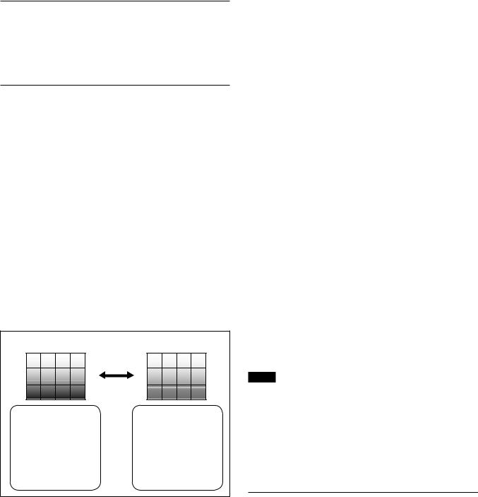
Wide Dynamic Range Auto On/Off Mode
The wide dynamic range can be set to be automatically switched ON/OFF in accordance with the intensity difference obtained by dividing an image into several blocks and then averaging the intensity of each block.
Wide Dynamic Range Auto On/Off Mode
Auto On/Off
When the intensity |
When the subject |
difference between the |
changes and the |
dark portions and light |
intensity difference |
portions of a subject |
between the dark |
becomes large because |
portions and light |
of back lighting or the |
portions becomes small, |
like, the wide dynamic |
the wide dynamic range |
range mode is switched |
mode is switched OFF. |
ON. |
|
The wide dynamic range mode includes the following operation modes.
WD Mode
This mode corrects blocked-up shadows and blownout highlights in accordance with the intensity difference.
WD Auto ON/OFF Mode
This mode switches WD ON/OFF automatically in accordance with the intensity difference of the subject.
Configure the sensitivity for when WD is switched from OFF to ON with the detection sensitivity parameter.
Basic Functions
Exposure Ratio Mode
This mode fixes the shutter speed of a long exposure. Configure the shutter speed of a short exposure by setting the ratio with regards to a long exposure with the exposure ratio parameter.
Blown-out highlight correction is not performed in this mode.
Histogram Mode
This mode uses a histogram to correct blocked-up shadows and blown-out highlights.
About WD Set Parameter
(Command: 8x 01 04 2D 0p 0q 0r 0s 0t 0u 00 00 FF)
p:Screen display (0: Combined image, 2: Long-time,
3:Short-time)
Set the screen display to the combined image, a long exposure image or short exposure image.
q: Detection sensitivity (0: Low, 1: Mid, 2: Hi) Select from three levels for detecting the intensity within the image for when switching Auto WD from OFF to ON.
r:Blocked-up shadow correction level can be set to one of four levels. (0:L 1:M 2:H 3:S)
s:Blown-out highlight correction level can be set to one of three levels. (0:L 1:M 2:H)
tu: |
Parameter to use in the exposure ratio mode. |
|
Specify the short exposure time by setting |
|
the magnification ratio (×1 to ×64) with |
|
regards to a long exposure time. |
Notes
•When the wide dynamic range mode is ON, solarization may be observed in the images of some subjects. This phenomenon is unique to wide dynamic range mode, and is not an indication of a camera malfunction.
•The frame rate during Wide Dynamic Range mode will be half of that during standard mode.
Example: When Wide Dynamic Range mode is ON in 1080/30P mode, the frame rate is 15 fps.
Noise Reduction
The NR (Noise Reduction) function removes noise (both random and non-random) to provide clearer images.
This function has six steps: levels 1 to 5, plus off. The NR effect is applied in levels based on the gain,
and this setting value determines the limit of the effect. In bright conditions, changing the NR level will not have an effect.
13

High Sensitivity Mode
In this mode, higher sensitivity gain is applied as standard gain increases, reaching a gain level at MAX gain of up to 4x the standard gain. In such cases, however, there will be a high volume noise in the image.
Custom Gamma Mode
Gamma correction can be changed in this mode. The following five options are available.
1:Standard
2:Straight gamma
3:S-curve - Low
4:S-curve - Mid
5:S-curve - High
Tip
Blocked-up shadows in images will be more noticeable than usual.
Slow shutter – Auto/Manual
When set to “Auto,” ensures that the slow shutter is set automatically when the brightness drops. Effective only when the AE mode is set to “Full Auto.”
Set to “Slow Shutter Manual” at shipment.
Note
The Slow Shutter Auto function is not available in WD mode.
Low-Illumination Chroma Suppress Mode
You can configure a chroma suppress mode for lowillumination conditions. This can be useful when color noise is particularly noticeable in such conditions. Four levels (disabled and three levels) are available for the low-illumination chroma suppress mode. Set the effect to be applied at approximately 15 dB. Higher setting values produce stronger chroma suppressing effects.
ICR (IR Cut-Removable) Mode
An infrared (IR) Cut-Filter can be disengaged from the image path for increased sensitivity in low light environments. The ICR will automatically engage depending on the ambient light, allowing the camera to be effective in day/night environments.
When the auto ICR mode is set to ON, the image becomes black and white.
Basic Functions
Custom Color Gain
You can customize and configure the color gain. Use this setting when bright color is particularly important. The initial setting 100% (4h) can be set to range from approx. 60% (Oh) to 200% (Eh) with 15 stages.
Custom Color Phase
You can customize and configure the color phase. The initial setting 0 degrees (7h) is adjustable between approx. −14 degrees (0h) and +14 degrees (Eh), in
15 increments.
Auto ICR Mode
Auto ICR Mode automatically switches the settings needed for attaching or removing the IR Cut Filter. With a set level of darkness, the IR Cut Filter is automatically disabled (ICR ON), and the infrared sensitivity is increased. With a set level of brightness, the IR Cut Filter is automatically enabled (ICR OFF). Also, on systems equipped with an IR light, the internal data of the camera is used to make the proper decisions to avoid malfunctions.
Auto ICR Mode operates with the AE Full Auto setting.
When Auto Slow Shutter is OFF (initial setting)
|
AGC |
Shutter 1/60 sec |
ICR |
IRIS |
|
MAX |
OPEN |
|
|
GAIN |
IRIS |
ICR ON |
|
SHUTTER |
Dark |
|
Bright |
ICR OFF U ON
When Auto Slow Shutter is ON
14

Note
When in Auto_ICR_OFF state and WB data is added (default), a malfunction may occur when the subjects largely consisting of blue and green colors are taken.
Camera ID
The ID can be set up to 65,536 (0000 to FFFF). As this will be memorized in the nonvolatile memory inside the camera, data will be saved regardless of whether it has been backed up.
Effect
It consists of the following functions.
•Neg. Art: Negative/Positive Reversal
•Black White: Monochrome Image
Checking the Location of the Camera for Signals from the IR Remote Commander
The supplied Remote Commander may not work correctly near inverter lighting fixtures. Good IR detection can be verified to determine proper camera location.
While the camera is being initialized after the power is turned on by connecting the camera to an AC outlet using the AC power adaptor and AC power cord, or by using a VISCA command, the camera detects whether or not the camera is able to receive infrared signals from the Remote Commander. You can check the result of this operation via the IR_ConditionInq command (see page 37).
When the installation location does not allow stable reception, try to install the camera farther away from the inverter lighting fixtures.
Others
Power On/Off
Powers the camera on and off. When the power is off, the camera is able to accept only the lowest level of VISCA Commands and POWER of the Remote Commander; the display and other features are turned off.
I/F clear
Clears the Command buffer of the camera. Clearing the buffer can also be carried out from the control application software when the power is on.
Address set
VISCA is a protocol, which normally can support a daisy chain of up to seven attached devices. Therefore, whenever a camera is connected for the first time, be sure to use the address set to confirm the address.
Basic Functions
Memory (Position Preset)
Using the position preset function, 6 sets of camera shooting conditions can be stored and recalled.
This function allows you to achieve the desired status instantly without adjusting the following items each time.
Pan/Tilt Position
Zoom Position
Digital Zoom On/Off
Focus Auto/Manual
Focus Position
AE Mode
Shutter control parameters
Bright Control
Iris control parameters
Gain control parameters
Exposure Compensation On/Off
Exposure Level
Backlight Compensation On/Off
Slow Shutter Auto/Manual
White Balance Mode
R/B Gain
Aperture
ICR Shoot On/Off
WD On/Off
The settings are recalled when the power is turned on.
For setting items, see the “Initial Settings, Position Preset” section on page 16.
Note
If the camera is placed on a desk, when you pan the camera to the right or left beyond 120° with the camera tilted downward by 20° (or tilted upward by 20° if it is installed on a ceiling), the camera base may be captured by the lens, depending on the zoom position of the lens.
15

Basic Functions
Initial Settings and Position Preset
The initial values are those set at the factory. Settings for items in Position presets 1 to 6 that will be retained even when the power to the camera is turned off are indicated by a “Yes,” those that will be lost are indicated by an “No.”
When the power is turned on, the settings retained in POSITION 1 will be called up as the initial settings.
When a CAM_Memory Reset command is sent, or a
choice is made from POSITION 1 to 6 while the RESET button on the Remote Commander is being pressed, the settings selected will be used as the initial settings.
Position preset 1 becomes VISCA command CAM_ Memory memory number 0. Position presets 2 through 6 become VISCA command CAM_Memory memory numbers 1 through 5.
Mode/Position |
Initial settings |
Position |
Position |
|
preset 1 |
presets 2 to 6 |
|||
|
|
|||
|
|
|
|
|
Pan/Tilt Position |
Home position |
|
|
|
Pan/Tilt Limit Position |
movable-range maximum |
|
|
|
Zoom Position |
Wide end |
|
|
|
D-Zoom On/Off |
On |
|
|
|
Focus Position |
— |
|
|
|
Focus Auto/Manual |
Auto |
|
|
|
Near Limit Setting |
D000h (30 cm) |
|
|
|
AF Sensitivity |
Normal |
|
|
|
AF Mode |
Normal |
|
|
|
AF Run Time |
5 sec |
|
|
|
AF Interval |
5 sec |
|
|
|
WB Mode |
Auto |
|
|
|
WB Data (Rgain, Bgain) |
— |
|
|
|
One Push WB Data |
— |
|
|
|
AE Mode |
Full Auto |
|
|
|
WD On/Off/Auto |
Off |
|
|
|
Slow Shutter Mode |
Manual |
|
|
|
Shutter Position |
1/30 sec |
|
|
|
Iris Position |
— |
|
|
|
Gain Position |
— |
|
|
|
Bright Position |
— |
|
|
|
Exposure Compensation On/Off |
Off |
|
|
|
Exposure Compensation Amount |
±0 |
|
|
|
BackLight On/Off |
Off |
|
|
|
Aperture Level |
08h |
|
|
|
High Resolution Mode On/Off |
Off |
|
|
|
Picture Effect |
Off |
|
|
|
ICR On/Off |
Off |
|
|
|
Auto ICR On/Off |
Off |
|
|
|
Auto ICR Threshold Level |
0Ah |
|
|
|
NR Level |
3 |
|
|
|
AE Gain Limit |
— |
|
|
|
Low-Illumination Chroma Suppress |
2h (Middle) |
|
|
|
Color Gain |
4h (100%) |
|
|
|
Color Hue |
7h (0degrees) |
|
|
|
Camera ID |
0000h |
|
|
|
IR_Receive On/Off |
On |
|
|
|
IR_ReceiveReturn On/Off |
Off |
|
|
|
Display Information |
On |
|
|
A circle “ ” in this column signifies that the data is preserved.
A cross “ ” signifies that the data IS NOT preserved.
16

Basic Functions
Notes
The number of times data can be written to the EEPROM (by executing Position Preset) is limited.
If you want the camera status and Pan/Tilt positions in effect before the camera is turned off to be retained when the power is turned OFF, then turned ON again, have the camera memorize those positions in POSITION 1.
It takes approximately 2 seconds longer to memorize or erase settings in POSITION 1 than it does to memorize or erase settings in any other channel.
Camera ID data will be saved regardless of the position preset.
If IMAGE FLIP or D70 mode has been switched, all of the Position Presets are reset to their initial values.
17
 Loading...