


A-BS4-100-11 (1)
Color Video Camera
Technical Manual
EVI-D70/D70P
2003 Sony Corporation
Table of Contents
Features ..................................................................... |
3 |
Connection ................................................................. |
4 |
Locations of Controls ............................................... |
5 |
Basic Functions ......................................................... |
7 |
Initial Settings, Position Preset ................................. |
25 |
Mode Condition ........................................................ |
27 |
Command List ......................................................... |
31 |
VISCA RS-232C/RS-422 Commands ...................... |
31 |
EVI-D70/P Commands ............................................. |
39 |
D30/D31 Mode .......................................................... |
52 |
Overview .................................................................. |
52 |
Switching the Mode .................................................. |
52 |
Accepting or Sending Back Commands ................... |
53 |
Translating Parameters ............................................ |
54 |
Specifications .......................................................... |
59 |
Precautions .............................................................. |
61 |
2

Overview
Features
•An EXview HAD CCD provides 380,000 (EVI-D70)/ 410,000 (EVI-D70P) effective picture elements (pixels) enabling high-resolution imaging with this camera.
•The use of VISCA commands allows you to control the camera from a computer.
•High-speed, wide angle PAN and TILT functions and Image Flip (turning the displayed image upside down) allow the unit to be mounted on the ceiling, broadening the range of uses for this versatile camera.
•With the addition of external RS-232C communication, RS-422 and VISCA commands provide the ability to remotely control this camera from greater distances.
•The lens offers an18x optical zoom feature.
•Use of a newly developed digital signal processor (DSP) improves the image quality of the digital zoom feature.
•An IR (infrared) cut filter can be physically removed. In addition, it can be switched on and off automatically, providing the optimum image quality for your subjects, whether they require high resolution or are poorly lit.
•Up to six combinations of camera position and settings can be retained in memory and called up when needed.
•A multi-function Remote Commander is also provided.
3

Connection
Connection
|
Video cable |
|
|
(not supplied) |
to Video |
|
|
|
|
|
input |
to VIDEO |
S-Video cable |
to |
|
||
|
(not supplied) |
|
|
S-Video |
|
|
|
|
|
|
input |
to S VIDEO VISCA cable |
|
|
|
(not supplied) 1) |
|
to VISCA RS-232C IN |
|
|
|
to RS-232C |
|
to VISCA |
RS-232C OUT |
To VISCA IN of other EVI-D70/ D70Ps (when connecting to more than one camera)
Computer, TV or VCR with a video input jack
to VISCA RS-422 2)
AC power adaptor MPA-AC1 (supplied)
to AC outlet
to DC IN 12V
Power cord (supplied)
1)When the camera is connected to a computer with a VISCA cable (cross type, RS-232C), you can operate the camera with the computer. To obtain a cable, consult the dealer where you bought your camera.
2)For more detail on the VISCA RS-422 connection, see page 36.
Notes |
|
|
• You cannot connect your Color Video Camera to a |
|
|
computer that is not equipped with either video input or an |
|
|
S-Video input connector. You might not be able to use |
|
|
your existing computer with your Color Video Camera |
Polarity of the plug |
|
unless you provide the computer with a video capture |
|
|
board and/or software. Consult your computer dealer or |
• Do not make VISCA RS-232C and RS-422 connections at |
|
manufacturer for details. |
the same time, as this may cause malfunctions. |
|
• Use only the AC power adaptor (MPAAC1) supplied with |
|
|
the unit. Do not use any other AC power adaptor. |
|
|
4

Locations of Controls
Locations of Controls
Main Unit
Front 1 2
3 4
Rear |
5 6 7 8 |
Bottom |
|
qf qg |
|
|||||||||
|
|
|
|
|
||||||||||
|
|
|
|
|
|
|
|
|
|
|
|
|
|
|
|
|
|
|
|
|
|
|
|
|
|
|
|
|
|
|
|
|
|
|
|
|
|
|
|
|
|
|
|
|
|
|
|
|
|
|
|
|
|
|
|
|
|
|
|
|
|
|
|
|
|
|
|
|
|
|
|
|
|
|
|
|
|
|
|
|
|
|
|
|
|
|
|
|
|
|
|
|
|
|
|
|
|
|
|
|
|
|
|
|
|
|
|
|
|
|
|
|
|
|
|
|
|
|
|
|
|
|
|
|
|
|
|
|
|
|
|
|
|
|
qh
9 q; qa qs qd
1Lens
A wide conversion lens can be attached.
2 Sensor for the Remote Commander
3 POWER lamp
4 STANDBY lamp
5 Sensor for the Remote Commander
6IMAGE FLIP switch
Flips the image upside down and executes Pan/Tilt movement according to the camera installation. Normally set this to OFF when you use the camera. When the camera is attached to the ceiling, set this to ON.
To change the mode, move the switch while the power
is off (including standby mode). Then turn on the power using DC power, VISCA command, or the Remote Commander.
After the mode has been changed, the pre-set setting saved by the Position Preset is returned to the initial setting.
It takes about 7 seconds for the image to be displayed after Pan/Tilt initialization motion has stopped.
Do not turn off DC power until the image has been displayed.
When the power is on, you cannot flip the image using this switch.
(Continued)
5
7 IR SELECT switch
8VISCA RS-422 connector
A VISCA RS-422 connector plug is attached to the
unit at the factory.
9 VIDEO (output) connector
0 S VIDEO (output) connector qa VISCA RS-232C IN connector
qs VISCA RS-232C OUT connector qd DC IN 12V connector
qf Tripod screw hole qg BOTTOM switch
D30 |
IR |
RS |
38400 |
||||
MODE |
OUT |
422 |
bps |
||||
|
|
|
|
|
|
|
|
|
|
|
|
|
|
|
|
OFF |
OFF |
RS |
9600 |
||||
|
|
|
|
232C |
bps |
||
1 |
2 |
3 |
4 |
||||
1 D30/D31 mode switch
Set this switch to ON to operate the Color Video Camera using the VISCA commands for the EVI-D30/ D31. (See page 52.)
2 IR SELECT switch
Set this switch to ON to allow the camera output signals transmitted from the Remote Commander to the Color Video Camera via VISCA OUT jack. (See page 35.)
3 RS-232C/RS-422 SELECT switch
Set this switch to RS422 to operate the Color Video Camera using the VISCA commands via the RS-422 interface.
To switch modes, make sure that the power is turned off (excluding standby mode), move the BOTTOM switch, and then turn the DC power on.
The unit will not switch modes after the power is turned on.
4 BAUD RATE SELECT switch
Set this switch to 38400 bps to operate the camera with the baud rate of 38400 bps.
To switch modes, make sure that the power is turned off (excluding standby mode), move the BOTTOM switch, and then turn the DC power on.
The unit will not switch modes after the power is turned on.
qh Ceiling bracket mounting screw holes
Locations of Controls
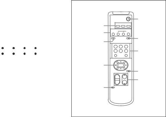
Remote Commander
|
|
|
POWER |
|
|
|
|
|
6 |
1 |
CAMERA SELECT |
|
||
1 |
2 |
3 |
|
|
|
FOCUS |
|
|
|
2 |
AUTO |
|
MANUAL |
|
FAR |
NEAR |
|
||
3 |
DATA SCREEN |
|
BACK LIGHT |
7 |
|
|
|
|
|
|
STD |
REV |
|
|
|
1 |
2 |
3 |
|
|
4 |
5 |
6 |
8 |
|
PRESET |
|
RESET |
|
|
POSITION |
|
|
|
|
PAN-TILT |
|
|
|
4 |
HOME |
|
|
|
|
|
|
PAN-TILT |
|
|
|
|
RESET |
9 |
|
SLOW ZOOM FAST |
|
||
|
T |
|
T |
q; |
|
W |
W |
||
|
|
|||
|
L/R |
5 |
DIRECTION SET |
RM-EV100 |
1 CAMERA SELECT buttons
2FOCUS buttons
AUTO button FAR button NEAR button
MANUAL button
3DATA SCREEN button
When the DATA SCREEN button is pushed, the camera status is displayed when you are using the Zoom or Manual Focus functions.
DATA SCREEN can be set to ON or OFF, and memorized, only with POSITION 1.
When POSITION 1 is recalled, the memorized DATA SCREEN status is used.
4 PAN-TILT button
Arrow buttons HOME button
5 L/R DIRECTION SET button
6 POWER switch
7 BACK LIGHT button
8POSITION buttons
Numeric buttons (Button 1 also works as the STD button. Button 2 also works as the REV button.) PRESET button
RESET button
9 PAN-TILT RESET button
0ZOOM buttons
SLOW T button SLOW W button FAST T button FAST W button
6

Basic Functions
Basic Functions
Zoom
The camera employs an 18× optical zoom lens combined with a digital zoom function allowing you to zoom up to 216×.
Lens specifications: Optical 18×, f = 4.1 to 73.8 mm (F1.4 to F3.0)
The horizontal angle of view is approximately 48 degrees (wide end) to 2.7 degrees (tele end). Digital Zoom enlarges the center of the subject by expanding each image in both the vertical and
horizontal directions. When 12× digital zoom is used, the number of effective picture elements in each direction reduces to 1/12 and the overall resolution deteriorates.
You can activate the zoom in the following two ways:
•By pressing the TELE or WIDE buttons on the Remote Commander.
•Using a VISCA Command
Using Standard Mode
Using Variable Mode
There are eight levels of zoom speed.
Direct Mode
Setting the zoom position enables quick movement to the designated position.
Digital Zoom ON/OFF
In these standard and variable Speed Modes, it is necessary to send a “Stop Command” to stop the zoom operation.
•The Zoom Mode supports a Combined Mode and a Separate Mode.
Combined Mode
This is the previously existing zoom method. After the optical zoom has reached its maximum level, the camera switches to Digital Zoom Mode.
Separate Mode
In this mode, Optical Zoom and Digital Zoom can be operated separately. You can use digital zoom magnification at any time from within any level of optical magnification.
Focus
Focus has the following modes, all of which can be set using VISCA Commands.
•Auto Focus Mode
The minimum focus distance is 10 mm at the optical wide end (extreme close-up settings with VISCA control) and 800 mm at the optical tele end (distance from the front end of the lens), and is independent of the digital zoom.
The AutoFocus (AF) function automatically adjusts the focus position to maximize the high frequency content of the picture in a center measurement area, taking into consideration the high luminance and strong contrast components.
- Normal AF Mode
This is the normal mode for AF operations.
- Interval AF Mode
The mode used for AF movements carried out at defined intervals. The time intervals for AF movements and for the timing of the stops can be set in one-second increments using the Set Time Command. The initial value for both is set to five seconds.
- Zoom Trigger Mode
When the zoom is changed with the TELE or the WIDE buttons, the pre-set value (initially set at 5 seconds) becomes that for AF Mode. Then, it returns to Manual Focus mode.
AF sensitivity can be set to either NORMAL or LOW.
- NORMAL
Reaches the highest focus speed quickly. Use this when shooting a subject that moves frequently. Usually, this is the most appropriate mode.
- LOW
Improves the stability of the focus. When the lighting level is low, the AF function does not take effect, even though the brightness varies, contributing to a stable image.
7

To avoid AF error from continuous 24 hour AF mode usage, daily initialization of lens system using the CAM_Initialize command is recommended.
The CAM_Initialize command takes less than 3 seconds to initialize the focus and zoom.
•Manual Focus Mode
MF (Manual Focus) has both a Standard Speed Mode and a Variable Speed Mode. Standard Speed Mode focuses at a fixed rate of speed. Variable Speed Mode has eight speed levels that can be set using a VISCA Command.
Will not stop by this command itself in Standard Speed Mode and Variable Speed Mode. To stop, a Stop command must be sent.
•One Push Trigger Mode
When a Trigger Command is received, the lens moves to adjust the focus for the subject. The focus lens then holds the same position until the next Trigger Command is input.
•Infinity Mode
The lens is forcibly moved to a position suitable for an unlimited distance.
•Near Limit Mode
Can be set in a range from 1000 (∞) to C000 (10 mm). The focus range is narrowed by excluding the unnecessary range.
White Balance
White Balance has the following modes, all of which can be set using VISCA Commands.
•Auto White Balance
This mode computes the white balance value output using color information from the entire screen. It outputs the proper value using the color temperature radiating from a black subject based on a range of values from 3000 to 7500K.
This mode is the default setting.
•ATW
Auto Tracing White balance (2000 to 10000 K)
•Indoor
3200 K Base Mode
•Outdoor
5800 K Base Mode
Basic Functions
•One Push WB
The One Push White Balance mode is a fixed white balance mode that may be automatically readjusted only at the request of the user (One Push Trigger), assuming that a white subject, in correct lighting conditions and occupying more than 1/2 of the image, is submitted to the camera.
One Push White Balance data is lost when the power is turned off. If the power is turned off, reset the One Push White Balance.
•Manual WB
Manual control of R and B gain, 256 steps each
Automatic Exposure Mode
The variety of AE functions, which allow video signal to output the optimum image for subjects from low light conditions to bright light conditions, are available.
•Full Auto
Auto Iris and Gain, Fixed Shutter Speed (NTSC: 1/60 s, PAL: 1/50 s)
•Shutter Priority 1)
Variable Shutter Speed, Auto Iris and Gain
(1/1 to 1/10,000 s, 22 steps, std. shutter: 16 steps, slow shutter: 6 steps)
•Iris Priority
Variable Iris (F1.4 to Close, 18 steps), Auto Gain and Shutter speed.
•Manual
Variable Shutter, Iris and Gain.
•Bright
Variable Iris and Gain (Close to F1.6, 17 steps at 0 dB: F1.4, 15 steps from 0 to 28 dB)
................................................................................................................................................................................................................................. |
|
1) Flicker can be eliminated by setting shutter to: |
t1/120 s for PAL models used in countries with a 60 Hz power supply |
t1/100 s for NTSC models used in countries with a 50 Hz power supply |
frequency. |
frequency. |
|
|
8 |
AE – Shutter Priority
The shutter speed can be set freely by the user to a total of 22 steps – 16 high speeds and 6 low speeds. When the slow shutter is set, the speed can be 1/30, 1/15, 1/8, or 1/4 s. The picture output is read at a normal
rate from the memory. The memory is updated at a low rate from the CCD. AF capability is low.
In high speed mode, the shutter speed can be set up to 1/10,000 s. The iris and gain are set automatically, according to the brightness of the subject.
Data |
NTSC |
PAL |
15 |
10000 |
10000 |
|
|
|
14 |
6000 |
6000 |
|
|
|
13 |
4000 |
3500 |
|
|
|
12 |
3000 |
2500 |
|
|
|
11 |
2000 |
1750 |
|
|
|
10 |
1500 |
1250 |
|
|
|
0F |
1000 |
1000 |
|
|
|
0E |
725 |
600 |
|
|
|
0D |
500 |
425 |
|
|
|
0C |
350 |
300 |
|
|
|
0B |
250 |
215 |
|
|
|
0A |
180 |
150 |
|
|
|
09 |
125 |
120 |
|
|
|
08 |
100 |
100 |
|
|
|
07 |
90 |
75 |
|
|
|
06 |
60 |
50 |
|
|
|
05 |
30 |
25 |
|
|
|
04 |
15 |
12 |
|
|
|
03 |
8 |
6 |
|
|
|
02 |
4 |
3 |
|
|
|
01 a) |
2 |
2 |
00 a) |
1 |
1 |
a) For AE-Manual only.
Note
When the shutter speed 1/1 s or 1/2 s is used, Auto Focus and White Balance may not function fully.
AE – Iris Priority
The iris can be set freely by the user to 18 steps between F1.4 and Close.
The gain and shutter speed are set automatically according to the brightness of the subject.
Data |
Setting value |
Data |
Setting value |
|
|
|
|
11 |
F1.4 |
08 |
F6.8 |
|
|
|
|
10 |
F1.6 |
07 |
F8.0 |
|
|
|
|
0F |
F2.0 |
06 |
F9.6 |
|
|
|
|
0E |
F2.4 |
05 |
F11 |
|
|
|
|
0D |
F2.8 |
04 |
F14 |
|
|
|
|
0C |
F3.4 |
03 |
F16 |
|
|
|
|
0B |
F4.0 |
02 |
F19 |
|
|
|
|
0A |
F4.8 |
01 |
F22 |
|
|
|
|
09 |
F5.6 |
00 |
CLOSE |
Basic Functions
AE – Manual
The shutter speed (22 steps), iris (18 steps) and gain (16 steps) can be set freely by the user.
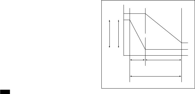
AE – Bright
The bright control function adjusts both the gain and iris using an internal algorithm according to a brightness level freely set by the user. Exposure is controlled by gain when dark and by iris when bright. As both gain and iris are fixed, this mode is used when exposing at a fixed camera sensitivity. When switching from Full Auto or Shutter Priority Mode to Bright Mode, the current status will be retained for a short period of time.
Only when the AE mode is set to “Full Auto” or “Shutter Priority,” the user can switch it to “Bright.”
Gain |
|
IRIS AGC |
|
OPEN MAX |
|
|
IRIS curve |
|
Gain curve |
CLOSE MIN |
|
Dark |
Bright |
Controlled |
Controlled by IRIS |
by gain |
|
Bright limit which controllable for this unit
Data |
Iris |
Gain |
Data |
Iris |
Gain |
1F |
F1.4 |
28 dB |
0F |
F2.0 |
0 dB |
|
|
|
|
|
|
1E |
F1.4 |
26 dB |
0E |
F2.4 |
0 dB |
|
|
|
|
|
|
1D |
F1.4 |
24 dB |
0D |
F2.8 |
0 dB |
|
|
|
|
|
|
1C |
F1.4 |
22 dB |
0C |
F3.4 |
0 dB |
|
|
|
|
|
|
1B |
F1.4 |
20 dB |
0B |
F4.0 |
0 dB |
|
|
|
|
|
|
1A |
F1.4 |
18 dB |
0A |
F4.8 |
0 dB |
|
|
|
|
|
|
19 |
F1.4 |
16 dB |
09 |
F5.6 |
0 dB |
|
|
|
|
|
|
18 |
F1.4 |
14 dB |
08 |
F6.8 |
0 dB |
|
|
|
|
|
|
17 |
F1.4 |
12 dB |
07 |
F8.0 |
0 dB |
|
|
|
|
|
|
16 |
F1.4 |
10 dB |
06 |
F9.6 |
0 dB |
|
|
|
|
|
|
15 |
F1.4 |
8 dB |
05 |
F11 |
0 dB |
|
|
|
|
|
|
14 |
F1.4 |
6 dB |
04 |
F14 |
0 dB |
|
|
|
|
|
|
13 |
F1.4 |
4 dB |
03 |
F16 |
0 dB |
|
|
|
|
|
|
12 |
F1.4 |
2 dB |
02 |
F19 |
0 dB |
|
|
|
|
|
|
11 |
F1.4 |
0 dB |
01 |
F22 |
0 dB |
|
|
|
|
|
|
10 |
F1.6 |
0 dB |
00 |
CLOSE |
0 dB |
|
|
|
|
|
|
9
When switching from the Shutter Priority mode to the Bright mode, the shutter speed set in the Shutter Priority mode is maintained.
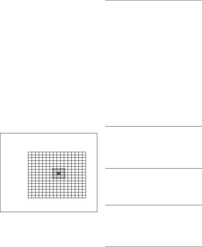
Spot Exposure Mode
In Full Auto AE, the level for the entire screen is computed and the optimum Auto Iris and Gain levels are determined. In Spot AE, a particular section of the subject can be designated, and then that portion of the image can be weighted and a value computed so that Iris and Gain can be optimized to obtain an image. For example, in an image with a lot of movement and with varying levels of brightness, portions without much change can be designated as such a “spot,” and changes to the screen can be minimized in that area. As shown in the diagram below, a range of 16 blocks vertically and 16 blocks horizontally can be designated.
In the case where the center is designated (shown in black), the level is computed along with a weighted value for the surrounding block (shaded), including the specified portions; and then the Gain and Iris are set. The value of the designated portions and the surrounding areas should be calculated as 90% and the rest should be set to 10%.
Horizontal 16
0 1 2 3 4 5 6 7 8 9 A B C D E F
0
1
2
Vertical 16 34
5
6
7
8
9 A B C D E F
Basic Functions
Exposure Compensation
Exposure compensation is a function which offsets the internal reference brightness level used in the AE mode by steps of 1.5 dB.
Data |
Step |
Setting value |
|
|
|
0E |
7 |
10.5 dB |
|
|
|
0D |
6 |
9 dB |
|
|
|
0C |
5 |
7.5 dB |
|
|
|
0B |
4 |
6 dB |
|
|
|
0A |
3 |
4.5 dB |
|
|
|
09 |
2 |
3 dB |
|
|
|
08 |
1 |
1.5 dB |
|
|
|
07 |
0 |
0 dB |
|
|
|
06 |
–1 |
–1.5 dB |
|
|
|
05 |
–2 |
–3 dB |
|
|
|
04 |
–3 |
–4.5 dB |
|
|
|
03 |
–4 |
–6 dB |
|
|
|
02 |
–5 |
–7.5 dB |
|
|
|
01 |
–6 |
–9 dB |
|
|
|
00 |
–7 |
–10.5 dB |
|
|
|
Aperture Control
Aperture control is a function which adjusts the enhancement of the edges of objects in the picture. There are 16 levels of adjustment, starting from “no enhancement.” When shooting text, this control may help by making the text sharper.
Back Light Compensation
When the background of the subject is too bright, or when the subject is too dark due to shooting in the AE mode, back light compensation will make the subject appear clearer.
Slow Shutter – Auto/Manual
When the Slow Shutter is set to “Auto,” this ensures that the slow shutter is engaged automatically when the brightness drops. This occurs only when the AE mode is set to “Full Auto.”
“Slow Shutter Manual” is the factory setting.
ICR (IR Cut-Removable) Mode
An infrared (IR) Cut-Filter can be disengaged from the image path for increased sensitivity in low light environments. The ICR will automatically engage depending on the ambient light, allowing the camera to be effective in day/night environments.
If you normally set the IR Cut-Filter to OFF, the image will be black and white (monochrome).
10
Auto ICR Mode
Auto ICR Mode automatically switches the settings needed for attaching or removing the IR Cut Filter. With a set level of darkness, the IR Cut Filter is automatically disabled (ICR ON), and the infrared sensitivity is increased. With a set level of brightness, the IR Cut Filter is automatically enabled (ICR OFF). Also on systems equipped with an IR light, the internal data of the camera is used to make the proper decisions to avoid malfunctions.
When Auto Slow Shutter is OFF (PRESLOW mode ON (default) or OFF)
ICR |
|
IRIS |
|
ON |
|
|
|
AGC |
OPEN |
|
|
|
|
||
|
|
|
|
(Iris Open) |
MAX |
|
|
|
|
|
|
(Gain Max) |
|
|
|
ICR ON |
|
|
IRIS |
|
GAIN |
|
|
|
|
|
(Iris Min) |
|
|
|
(0dB) |
|
Adjustable |
|
(1/60 sec) |
|
|
SHUTTER |
|
Dark |
|
|
Bright |
|
ICR ON t OFF Adjustable |
|
|
When Auto Slow Shutter is ON (PRESLOW mode OFF)
ICR |
|
IRIS |
|
AGC |
OPEN |
|
|
ON |
|
||
|
|
||
(Iris Open) |
MAX |
|
|
|
|
|
|
(Gain Max) |
|
|
|
ICR ON |
|
|
IRIS |
(Slow Shutter Max) |
GAIN |
|
|
|
|
|
|
|
|
|
(Iris Min) |
|
|
|
(0dB) |
|
Adjustable |
|
(1/60 sec) |
|
|
SHUTTER |
|
Dark |
|
|
Bright |
ICR ON t OFF Adjustable |
|
||
When Auto Slow Shutter is ON (PRESLOW mode ON (default))
ICR |
|
IRIS |
ON |
AGC |
OPEN |
(Iris Open) |
MAX |
|
|
|
|
(Gain Max) |
|
|
ICR ON |
|
IRIS |
(Slow Shutter Max) |
GAIN |
|
|
|
|
|
|
(Iris Min) |
|
|
(0dB) |
|
Adjustable |
(1/60 sec) |
|
SHUTTER |
|
Dark |
|
Bright |
|
ICR ON t OFF Adjustable |
|
Basic Functions
Note
When in Auto_ICR_OFF state and WB data is added (default), a malfunction may occur when the subjects largely consisting of blue and green colors are taken. Auto ICR is available in AE-full-auto state only.
Camera ID
The ID can be set up to 65,536 (0000 to FFFF). As this will be memorized in the nonvolatile memory inside the camera, data will be saved, regardless of the “position preset.”
Effect
It consists of the following functions.
•Neg. Art: Negative/Positive Reversal
•Black White: Monochrome Image
Others
IMAGE FLIP
The image output by the camera is flipped upside down, and the direction of Pan/Tilt movements are reversed using the IMAGE FLIP switch on the back of the unit.
Mirror Image
This function reverses the video output from the camera horizontally.
Freeze
This function captures an image in the field memory of the camera so that this image can be output continuously.
Because communication inside the camera is based on V cycle, the captured image is always the one 3V to 4Vs after the sending of a Command. Thus, you can not specify a time period after sending EVEN, ODD or a Command.
Power On/Off
Powers the camera on and off. When the power is off, the camera is able to accept only the lowest level of VISCA Commands and POWER of the Remote Commander; the display and other features are turned off.
I/F clear
Clears the Command buffer of the camera. Clearing the buffer can also be carried out from the control application software when the power is on.
Address set
VISCA is a protocol, which normally can support a daisy chain of up to seven attached devices. Therefore, whenever a camera is connected for the first time, be sure to use the address set to confirm the address.
11
Mute
Blanks the screen and sends out a synchronizing signal.
Lens Initialization
Initializes the zoom and focus of the lens. Even when power is already on, it initializes the zoom and the focus.
AutoPowerOff
If an operation is not attempted via either a VISCA command or the remote controller during a pre-set time period (from 1 to 65,535 minutes), the power will automatically turn off (Standby). To disable this function, set the time period to 0 minutes.
NightPowerOff
When the Alarm function operates in DayNight mode, and the unit judges that it is night, if an operation is not attempted via either a VISCA command or the remote controller during a pre-set time period (from 1 to 65,535 minutes), the power will automatically turn off (Standby). To disable this function, set the time period to 0 minutes.
When the DayNight level is set correctly (the Day level > the Night level), the Alarm function can only be set when the unit is operated in DayNight mode.
For information on DayNight mode settings, see pages 13, 14, and 24.
AutoPowerOff and NightPowerOff can be used at the same time.
However, if the criteria for both are fulfilled at the same time, the shorter of the two time periods until shut down will be used to turn the power off (Standby).
Memory (Position Preset)
Using the position preset function, 6 sets of camera shooting conditions can be stored and recalled.
This function allows you to achieve the desired status instantly even without adjusting the following items each time:
•Pan-Tilt position
•Zoom Position
•Digital Zoom On/Off
•Focus Auto/Manual
•Focus Position
•AE Mode
•Shutter control parameters
•Bright Control
•Iris control parameters
•Gain control parameters
•Exposure Compensation On/Off
•Exposure Level
•Backlight Compensation On/Off
Basic Functions
•Slow Shutter Auto/Manual
•White Balance Mode
•R/B Gain
•Aperture
•ICR Shoot On/Off
The settings are recalled when the power is turned on.
For setting items, see the “Initial Settings, Position Preset” section on page 25.
Alarm
For details, see page 13.
12

Title Display
The camera can be given a title containing up to 20 characters such as “ENTRANCE” or “LOBBY”. The position of the first character (horizontal, vertical) of the title, blinking state, and color can also be changed.
Vposition |
|
|
|
00 to 0A |
|
|
||
|
|
|
|
|
|
|
|
|
Hposition |
|
|
|
00 to 17 |
|
|
||
|
|
|
|
|
|
|
||
Blink |
|
|
|
00: Does not blink |
|
|||
|
|
|
|
|
|
|
|
|
|
|
|
|
01: Blinks |
|
|
||
|
|
|
|
|
|
|
||
|
|
|
|
|
|
|
|
|
|
|
|
|
00 |
|
|
White |
|
|
|
|
|
|
|
|
|
|
|
|
|
|
01 |
|
|
Yellow |
|
|
|
|
|
|
|
|
|
|
|
|
|
|
02 |
|
|
Violet |
|
|
|
|
|
|
|
|
|
|
Color |
|
|
|
03 |
|
|
Red |
|
|
|
|
|
|
|
|
|
|
|
|
|
|
04 |
|
|
Cyan |
|
|
|
|
|
|
|
|
|
|
|
|
|
|
05 |
|
|
Green |
|
|
|
|
|
|
|
|
|
|
|
|
|
|
06 |
|
|
Blue |
|
|
|
|
|
|
|
|
|
|
|
|
|
|
|
|
|
|
|
00 |
01 |
02 |
03 |
04 |
05 |
|
06 |
07 |
|
|
|
|
|
|
|
|
|
A |
B |
C |
D |
E |
F |
G |
H |
|
|
|
|
|
|
|
|
|
|
08 |
09 |
0a |
0b |
0c |
0d |
0e |
0f |
|
|
|
|
|
|
|
|
|
|
I |
J |
K |
L |
M |
N |
O |
P |
|
|
|
|
|
|
|
|
|
|
10 |
11 |
12 |
13 |
14 |
15 |
|
16 |
17 |
|
|
|
|
|
|
|
|
|
Q |
R |
S |
T |
U |
V |
W |
X |
|
|
|
|
|
|
|
|
|
|
18 |
19 |
1a |
1b |
1c |
1d |
1e |
1f |
|
|
|
|
|
|
|
|
|
|
Y |
Z |
& |
|
? |
! |
|
1 |
2 |
|
|
|
|
|
|
|
|
|
20 |
21 |
22 |
23 |
24 |
25 |
|
26 |
27 |
|
|
|
|
|
|
|
|
|
3 |
4 |
5 |
6 |
7 |
8 |
|
9 |
0 |
|
|
|
|
|
|
|
|
|
28 |
29 |
2a |
2b |
2c |
2d |
2e |
2f |
|
|
|
|
|
|
|
|
|
|
À |
È |
Ì |
Ò |
Ù |
Á |
|
É |
Í |
|
|
|
|
|
|
|
|
|
30 |
31 |
32 |
33 |
34 |
35 |
|
36 |
37 |
|
|
|
|
|
|
|
|
|
Ó |
Ú |
 |
Ê |
Ô |
Æ |
|
Π|
à |
|
|
|
|
|
|
|
|
|
38 |
39 |
3a |
3b |
3c |
3d |
3e |
3f |
|
|
|
|
|
|
|
|
|
|
Õ |
Ñ |
Ç |
ß |
Ä |
Ï |
|
Ö |
Ü |
|
|
|
|
|
|
|
|
|
40 |
41 |
42 |
43 |
44 |
45 |
|
46 |
47 |
|
|
|
|
|
|
|
|
|
Å |
$ |
F |
¥ |
DM |
£ |
|
¿ |
¡ |
|
|
|
|
|
|
|
|
|
48 |
49 |
4a |
4b |
4c |
4d |
4e |
4f |
|
|
|
|
|
|
|
|
|
|
ø |
“ |
: |
‘ |
. |
, |
|
/ |
- |
|
|
|
|
|
|
|
|
|
Basic Functions
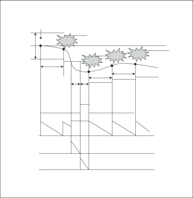
Alarm Function
This function instructs the camera to detect movement within the monitoring area and then send an alarm signal automatically.
A High level signal is output when camera detects movement inside the monitoring area. A Low level signal is output when object stops moving.
However, when the mode is set to “DAY/NIGHT”, the High level signal is output for dark and the Low level signal is output for bright.
The Detect signal goes out through the serial command (VISCA) communication line.
Example
1.A door is motionless, so the Detect Level is Low.
2.At the moment when the door is opened by someone, the Detect Level goes to High.
3.The Detect Level is High while the shooting object is moving.
4.When the door is closed, Detect Level goes to Low again, or signals are output only once at the time of switching between High Level and Low Level.
13

Basic Functions
ALARM Setting Command List
Command Set |
Command |
|
Command Packet |
Comments |
|||
CAM_Alarm |
On |
|
|
8x |
01 04 |
6B 02 FF |
MD start |
|
|
|
|
|
|
|
|
|
Off |
|
|
8x |
01 04 |
6B 03 FF |
MD stop |
|
|
|
|
|
|
|
|
|
Set Mode |
|
8x |
01 04 |
6C pp FF |
Mode Setting |
|
|
|
|
|
|
|
|
*Select one from 13 modes |
|
|
|
|
|
|
|
|
|
Set Day Night Level |
8x |
01 04 |
6D 0p 0p 0p |
ppp: Day distinction AE level |
||
|
|
|
|
0q |
0q 0q |
FF |
qqq: Night distinction AE level. |
|
|
|
|
|
|
|
|
|
|
|
|
|
|
|
|
|
|
|
|
90 |
07 04 |
6B 01 FF |
High signal output |
|
|
|
|
|
|
|
(Low t High edge) |
|
|
|
|
|
|
|
|
|
|
|
|
90 |
07 04 |
6B 00 FF |
Low signal output |
|
|
|
|
|
|
|
(High t Low edge) |
|
|
|
|
|
|
|
|
|
|
|
|
|
|
|
|
VISCA Mode Code (pp) |
Details of Mode |
|
|
|
|
||
|
|
|
|
||||
00 |
|
Set the internal focus position. When focus movement is detected, the detect signal is High. When focus goes |
|||||
|
|
back to the previous position, the detect signal is Low. |
|
||||
|
|
|
|
||||
01 |
|
Set a fixed period of time. When focus does not move during the time, the focus position is memorized as a |
|||||
|
|
rest position and the detect signal is Low. |
|
|
|||
|
|
When focus moves, the detect signal is High. Afterwards when focus does not move for the fixed period of |
|||||
|
|
time, the focus position is memorized and the detect signal becomes Low. |
|||||
|
|
|
|
||||
02 |
|
Set the internal AE Level. When AE movement is detected, the detect signal is High. When AE Level goes |
|||||
|
|
back to the previous level, the detect signal is Low. |
|
||||
|
|
|
|
||||
03 |
|
Set a fixed period of time. When AE Level does not change during this time, the AE value is memorized as a |
|||||
|
|
rest value and the detect signal is Low. |
|
|
|||
|
|
When AE value changes, the detect signal is High. |
|
||||
|
|
Afterwards when AE value does not change for the fixed period of time, the AE value is memorized and the |
|||||
|
|
detect signal becomes Low. |
|
|
|
|
|
|
|
|
|
|
|
|
|
04 |
|
mode “00” and mode “02” |
|
|
|
|
|
|
|
|
|
|
|
|
|
05 |
|
mode “00” and mode “03” |
|
|
|
|
|
|
|
|
|
|
|
|
|
06 |
|
mode “01” and mode “02” |
|
|
|
|
|
|
|
|
|
|
|
|
|
07 |
|
mode “01” and mode “03” |
|
|
|
|
|
|
|
|
|
|
|
|
|
08 |
|
mode “00” or mode “02” |
|
|
|
|
|
|
|
|
|
|
|
|
|
09 |
|
mode “00” or mode “03” |
|
|
|
|
|
|
|
|
|
|
|
|
|
0A |
|
mode “01” or mode “02” |
|
|
|
|
|
|
|
|
|
|
|
|
|
0B |
|
mode “01” or mode “03” |
|
|
|
|
|
|
|
|
|
|
|
|
|
0C |
|
Day-Night Mode |
|
|
|
|
|
|
|
|
|
|
|
|
|
|
|
|
|
|
|
|
|
ALARM Inquiry Command List |
|
|
|
|
|||
|
|
|
|
|
|
||
Inquiry Command |
|
|
Command Packet |
Inquiry Packet |
Comments |
||
CAM_Alarm Inq |
|
|
8x 09 04 6B FF |
y0 |
50 02 FF |
On |
|
|
|
|
|
|
|
|
|
|
|
|
|
y0 |
50 03 FF |
Off |
|
|
|
|
|
|
|
||
CAM_Alarm Mode Inq |
|
8x 09 04 6C FF |
y0 |
50 pp FF |
pp: Alarm Mode |
||
|
|
|
|
|
|
||
CAM_AlarmDayNightLevel Inq |
8x 09 04 6D FF |
y0 |
50 0p |
0p 0p |
ppp: Day setting AE Level |
||
|
|
|
|
0q |
0q 0q |
0r 0r 0r FF |
qqq: Night setting AE Level |
|
|
|
|
|
|
|
rrr: Now AE Level |
|
|
|
|
|
|
|
|
CAM_AlarmDetLevelInq |
|
8x 09 04 6E FF |
y0 |
50 01 |
FF |
Detect Level is High. |
|
|
|
|
|
y0 |
50 00 |
FF |
Detect Level is Low. |
|
|
|
|
|
|
|
|
14
Basic Functions
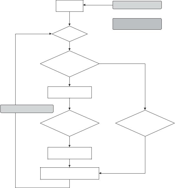
Flowchart of 12 Modes Function
Mode “00”
Set the Focus Position
Set to the factory preset
Hysteresis.
Alarm On |
Focus Position into memory |
AE moves
Focus moves outside of the hysteresis.
*
High level signal output
* Repeat this loop until Alarm off.
Focus goes back to the previous position.
Low level signal output
Far
Hysteresis
Focus
Position
Near High
Low
15
Mode “01”
Alarm On
AE moves.
Focus moves outside of the hysteresis.
*
* Repeat this loop until Alarm off.
High level signal output
AE does not move for a period of time.
Low level signal output
Update the Focus position data.
Basic Functions
Focus Position into memory
Hysteresis is set to the factory preset.
AE does not move for a period of time.
16
Basic Functions
Mode “02”
Set the AE level Hysteresis. |
Set to the factory preset |
Alarm On |
AE Level into memory |
AE moves.
AE moves outside of the hysteresis.
*
High level signal output
* Repeat this loop until Alarm off.
AE goes back to the previous level.
Low level signal output
Bright
Hysteresis
AE Level
Dark High
Low
17

Mode “03”
Alarm On
AE moves.
AE moves outside of the hysteresis.
High level signal output
*
* Repeat this loop until Alarm off.
AE does not move for a period of time.
Low level signal output
Update the AE level data
Basic Functions
AE level into memory
Hysteresis is set to the factory preset.
AE does not move for a period of time.
18
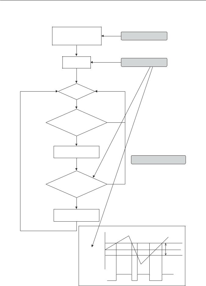
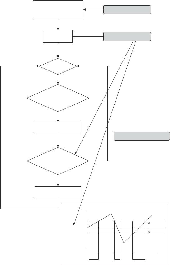
Basic Functions
Details of Mode “01” to “03”
T1: Reset interval timer (5sec)
T2: Detect timer (2sec)
T3: High level signal count timer (2sec)
Alarm ON
Hysteresis |
Reset |
|
|
|
|
Focus Pos/ |
|
|
AE Level |
|
|
|
|
Reset |
|
|
Reset |
|
|
Reset |
|
T1 |
T1 |
|
|
|
|
|
T1 |
|
T2 |
T3 |
|
|
High |
|
Low |
Low |
Signal level
T1:
T2:
T3:
19
 Loading...