


|
CDX-GT33U |
|
SERVICE MANUAL |
AEP Model |
|
Ver. 1.0 2009.03 |
UK Model |
|
E Model |
||
|
Photo: E model
• The tuner and CD sections have no adjustments. |
Model Name Using Similar Mechanism |
CDX-GT430U/GT434U |
|
||
|
|
|
|
CD Drive Mechanism Type |
MG-101Y-188//Q |
|
|
|
|
Optical Pick-up Name |
DAX-25A |
CD Player section
Signal-to-noise ratio: 120 dB Frequency response: 10 – 20,000 Hz
Wow and flutter: Below measurable limit
Tuner section
FM
Tuning range:
87.5 – 108.0 MHz (AEP, UK, IT, RU model)
87.5 – 107.9 MHz (E, MX model)
Antenna (aerial) terminal:
External antenna (aerial) connector
Intermediate frequency: 150 kHz Usable sensitivity: 10 dBf Selectivity: 75 dB at 400 kHz Signal-to-noise ratio: 70 dB (mono) Separation: 40 dB at 1 kHz Frequency response: 20 – 15,000 Hz
SPECIFICATIONS
AM (E, MX model)
Tuning range: 530 – 1,710 kHz
Antenna (aerial) terminal:
External antenna (aerial) connector
Intermediate frequency: 25 kHz Sensitivity: 26 V
MW/LW (AEP, UK, IT, RU model)
Tuning range:
MW: 531 – 1,602 kHz LW: 153 – 279 kHz
Antenna (aerial) terminal:
External antenna (aerial) connector
Intermediate frequency: 25 kHz
Sensitivity: MW: 26 V, LW: 45 V
USB Player section
Interface: USB (Full-speed)
Maximum current: 500mA
Power amplifier section
Outputs: Speaker outputs (sure seal connectors)
Speaker impedance: 4 – 8 ohms
Maximum power output: 45 W × 4 (at 4 ohms)
– Continued on next page –
AEP, UK, Italian, Russian model
FM/MW/LWCOMPACT DISC PLAYER
E, Mexican model
FM/AM COMPACT DISC PLAYER
9-889-450-01 |
Sony Corporation |
2009C04-1 |
Audio&Video Business Group |
© 2009.03 |
Published by Sony Techno Create Corporation |
CDX-GT33U
General
Output:
Power antenna (aerial) relay control terminal
Inputs:
Telephone ATT control terminal (AEP, UK, IT, RU model) Remote controller input terminal Antenna (aerial) input terminal AUX input jack (stereo mini jack)
Tone controls:
Low: ±10 dB at 60 Hz (XPLOD)
Mid: ±10 dB at 1 kHz (XPLOD)
High: ±10 dB at 10 kHz (XPLOD)
Power requirements: 12 V DC car battery (negative ground (earth))
Dimensions: Approx. 178 × 50 × 179 mm (7 1/8 × 2 × 7 1/8 in.) (w/h/d)
Mounting dimensions: Approx. 182 × 53 × 162 mm (7 1/4 × 2 1/8 × 6 1/2 in.) (w/h/d)
Mass: Approx. 1.2 kg (2 lb. 11 oz.)
Supplied accessories:
Card remote commander: RM-X151 (E, MX model) Parts for installation and connections (1 set)
Design and specifi cations are subject to change without notice.
• Abbreviation
IT |
: Italian model |
RU |
: Russian model |
MX |
: Mexican model |
NOTES ON HANDLING THE OPTICAL PICK-UP BLOCK OR BASE UNIT
The laser diode in the optical pick-up block may suffer electrostatic break-down because of the potential difference generated by the charged electrostatic load, etc. on clothing and the human body.
During repair, pay attention to electrostatic break-down and also use the procedure in the printed matter which is included in the repair parts.
The flexible board is easily damaged and should be handled with care.
NOTES ON LASER DIODE EMISSION CHECK
The laser beam on this model is concentrated so as to be focused on the disc reflective surface by the objective lens in the optical pickup block. Therefore, when checking the laser diode emission, observe from more than 30 cm away from the objective lens.
NOTES ON CHIP COMPONENT REPLACEMENT
•Never reuse a disconnected chip component.
•Notice that the minus side of a tantalum capacitor may be damaged by heat.
TEST DISCS
Please use the following test discs for the check on the CD section.
YDES-18 (Part No. 3-702-101-01)
PATD-012 (Part No. 4-225-203-01)
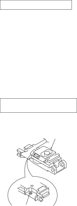
CAUTION
Use of controls or adjustments or performance of procedures other than those specifi ed herein may result in hazardous radiation exposure.
If the optical pick-up block is defective, please replace the whole optical pick-up block.
Never turn the semi-fixed resistor located at the side of optical pick-up block.
optical pick-up
semi-fixed resistor
SAFETY-RELATED COMPONET WARNING!
COMPONENTS IDENTIFIED BY MARK 0 OR DOTTED LINE
WITH MARK 0 ON THE SCHEMATIC DIAGRAMS AND IN
THE PARTS LIST ARE CRITICAL TO SAFE OPERATION.
REPLACE THESE COMPONENTS WITH SONY PARTS
WHOSE PART NUMBERS APPEAR AS SHOWN IN THIS
MANUAL OR IN SUPPLEMENTS PUBLISHED BY SONY.
2
CDX-GT33U
This compact disc player is classified as a CLASS 1 LASER product. The CLASS 1 LASER PRODUCT label is located on the exterior.
This label is located on the bottom of the chassis.
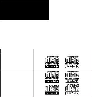
•CD playback
You can play CD-DA (also containing CD TEXT), CD-R/CD- RW (MP3/WMA/AAC files).
Type of discs |
Label on the disc |
CD-DA
MP3
WMA
AAC
UNLEADED SOLDER
Boards requiring use of unleaded solder are printed with the leadfree mark (LF) indicating the solder contains no lead.
(Caution: Some printed circuit boards may not come printed with the lead free mark due to their particular size)
 : LEAD FREE MARK
Unleaded solder has the following characteristics.
•Unleaded solder melts at a temperature about 40 °C higher than ordinary solder.
Ordinary soldering irons can be used but the iron tip has to be applied to the solder joint for a slightly longer time. Soldering irons using a temperature regulator should be set to about 350 °C.
Caution: The printed pattern (copper foil) may peel away if the heated tip is applied for too long, so be careful!
•Strong viscosity
Unleaded solder is more viscous (sticky, less prone to flow) than ordinary solder so use caution not to let solder bridges occur such as on IC pins, etc.
•Usable with ordinary solder
It is best to use only unleaded solder but unleaded solder may also be added to ordinary solder.
|
TABLE OF CONTENTS |
|
1. |
SERVICE NOTE ..................................................... |
4 |
2. |
GENERAL |
|
|
Location of Controls ....................................................... |
5 |
|
Connections .................................................................... |
7 |
3.DISASSEMBLY
3-1. |
Sub Panel Assy ............................................................... |
11 |
3-2. |
CD Mechanism Block..................................................... |
11 |
3-3. |
MAIN Board ................................................................... |
12 |
3-4. |
SERVO Board................................................................. |
12 |
3-5. |
Chassis (T) Sub Assy ...................................................... |
13 |
3-6. |
Roller Arm Assy.............................................................. |
13 |
3-7. |
Chassis (OP) Assy........................................................... |
14 |
3-8. |
Chucking Arm Sub Assy................................................. |
14 |
3-9. |
Sled Motor Assy.............................................................. |
15 |
3-10. |
Optical Pick-up Section .................................................. |
16 |
3-11. |
Optical Pick-up ............................................................... |
16 |
4.DIAGRAMS
4-1. Block Diagram –Main Section– ..................................... |
17 |
|
4-2. Block Diagram –Display Section– ................................. |
18 |
|
4-3. Printed Wiring Board –Main Section–............................ |
20 |
|
4-4. Schematic Diagram –Main Section (1/3)–...................... |
21 |
|
4-5. |
Schematic Diagram –Main Section (2/3)–...................... |
22 |
4-6. |
Schematic Diagram –Main Section (3/3)–...................... |
23 |
4-7. |
Printed Wiring Boards –Key Section–............................ |
24 |
4-8. |
Schematic Diagram –Key Section– ................................ |
25 |
5.EXPLODED VIEWS
5-1. |
Main Section ................................................................... |
30 |
5-2. |
Front Panel Section......................................................... |
31 |
5-3. |
CD Mechanism Section (MG-101Y-188//Q).................. |
32 |
6. |
ELECTRICAL PARTS LIST .............................. |
33 |
3
CDX-GT33U
SECTION 1
SERVICE NOTE
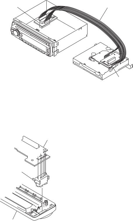
EXTENSION CABLE AND SERVICE POSITION
When repairing or servicing this set, connect the jig (extension cable) as shown below.
•Connect the MAIN board (CN701) and the SERVO board (CN401) with the extension cable (Part No. J-2502-076-1).
MAIN BOARD
CN701
J-2502-076-1
SERVO BOARD
CN401
NOTE FOR REPLACEMENT OF THE USB CONNECTOR (CN902)
To replace the USB connector requires alignment.
1.Insert the USB connector into the front panel.
2.Place the KEY board on the front panel and align the terminals of the USB connector with the holes in the KEY board.
3.Solder the four terminals of the connector.
KEY board
NOTE FOR REPLACEMENT OF THE SERVO BOARD
When repairing, the complete SERVO board (Part No. A-1555- 002-A) should be replaced since any parts in the SERVO board cannot be repaired.
NOTE FOR THE 20-PIN CONNECTOR (CN901)
Do not use alcohol to clean the 20-pin connector (CN901) connecting the front panel with the main body.
Do not touch the connector directly with your bare hand. Poor contact may be caused.
USB (socket) connector
front panel
4
CDX-GT33U
SECTION 2
GENERAL This section is extracted from instruction manual.
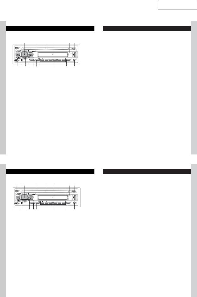
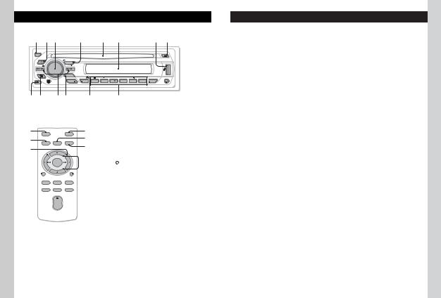
•Location of Controls
•AEP, UK, Italian model
Location of controls and basic operations
Main unit
|
|
|
|
|
|
|
|||
OFF |
|
|
|
|
|
|
|
|
|
BROWSE |
PUSH ENTER / SELECT |
|
|
|
|
|
|
|
|
SEEK |
SOURCE |
|
|
|
|
|
|
|
|
SEEK |
|
|
|
|
|
|
|
|
|
BACK |
MODE |
|
|
|
|
|
|
|
|
|
|
|
|
|
|
|
|
|
|
|
|
PTY |
ALBUM |
|
REP |
SHUF |
DM |
PAUSE |
SCRL |
|
EQ3 |
AF/TA |
1 |
2 |
3 |
4 |
5 |
6 |
DSPL |
|
|
|
This section contains instructions on the location of controls and basic operations. For details, see the respective pages.
For USB device operation, see “USB devices” on page 11.
OFF button
To power off; stop the source.
 (BROWSE) button page 8
To enter the Quick-BrowZer mode.
Control dial/select button page 8, 12
To adjust volume/select search category (rotate); select setup items (press and rotate).
SOURCE button
To power on; change the source (Radio/CD/ USB/AUX).
Disc slot
Insert the disc (label side up), playback starts.
Display window
USB terminal page 11
To connect to the USB device.
(eject) button
To eject the disc.
 (front panel release) button page 5
 (BACK) button page 8
To return to the previous display.
Receptor for the card remote commander
SEEK –/+ buttons
CD/USB:
To skip tracks (press); skip tracks continuously (press, then press again within about 1 second and hold); reverse/fastforward a track (press and hold).
Radio:
To tune in stations automatically (press); find a station manually (press and hold).
MODE button page 9
To select the radio band (FM/MW/LW).
EQ3 (equalizer) button page 12
To select an equalizer type (XPLOD, VOCAL, EDGE, CRUISE, SPACE, GRAVITY, CUSTOM or OFF).
AF (Alternative Frequencies)/ TA (Traffic Announcement)/
PTY (Program Type) button page 10, 11
To set AF and TA (press); select PTY (press and hold) in RDS.
RESET button (located behind the front panel) page 4
Number buttons
CD/USB:
/ : ALBUM –/+
To skip albums (press); skip albums continuously (press and hold).
: REP page 9
: SHUF page 9
: DM+
Improves digitally compressed sound, such as MP3.
To activate the DM+ function, set “DM+-ON.” To cancel, set “DM+- OFF.”
: PAUSE
To pause playback. To cancel, press again.
Radio:
To receive stored stations (press); store stations (press and hold).
DSPL (display)/SCRL (scroll) button page 9, 10, 12
To change display items (press); scroll the display item (press and hold).
AUX input jack page 14
To connect a portable audio device.
Note
When ejecting/inserting a disc, keep any USB devices disconnected to avoid damage to the disc.
6 |
7 |
• Russian model
Ɋɚɫɩɨɥɨɠɟɧɢɟ ɨɪɝɚɧɨɜ ɭɩɪɚɜɥɟɧɢɹ ɢ ɨɫɧɨɜɧɵɟ ɨɩɟɪɚɰɢɢ
Ɉɫɧɨɜɧɨɟ ɭɫɬɪɨɣɫɬɜɨ
|
|
|
|
|
|
|
|
||
OFF |
|
|
|
|
|
|
|
|
|
BROWSE |
PUSH ENTER / SELECT |
|
|
|
|
|
|
|
|
SEEK |
SOURCE |
|
|
|
|
|
|
|
|
SEEK |
|
|
|
|
|
|
|
|
|
BACK |
MODE |
|
|
|
|
|
|
|
|
|
|
|
|
|
|
|
|
|
|
|
|
PTY |
|
ALBUM |
REP |
SHUF |
DM |
PAUSE |
SCRL |
|
EQ3 |
AF/TA |
1 |
2 |
3 |
4 |
5 |
6 |
DSPL |
|
|
|
ȼ ɷɬɨɦ ɪɚɡɞɟɥɟ ɫɨɞɟɪɠɚɬɫɹ ɫɜɟɞɟɧɢɹ ɨ ɪɚɫɩɨɥɨɠɟɧɢɢ ɨɪɝɚɧɨɜ ɭɩɪɚɜɥɟɧɢɹ ɢ ɨɫɧɨɜɧɵɯɨɩɟɪɚɰɢɹɯ. ɉɨɞɪɨɛɧɵɟɫɜɟɞɟɧɢɹ ɫɦ. ɧɚ ɫɨɨɬɜɟɬɫɬɜɭɸɳɢɯ ɫɬɪɚɧɢɰɚɯ. ɉɨɞɪɨɛɧɟɟ ɨ ɪɚɛɨɬɟ ɫ ɭɫɬɪɨɣɫɬɜɨɦ USB ɫɦ. ɪɚɡɞɟɥ “ɍɫɬɪɨɣɫɬɜɚ USB” ɧɚ ɫɬɪ. 12.
Ʉɧɨɩɤɚ OFF
ȼɵɤɥɸɱɟɧɢɟ ɩɢɬɚɧɢɹ; ɨɫɬɚɧɨɜɤɚ ɢɫɬɨɱɧɢɤɚ.
Ʉɧɨɩɤɚ  (BROWSE) ɫɬɪ. 8
ɉɟɪɟɤɥɸɱɟɧɢɟ ɜ ɪɟɠɢɦ Quick-BrowZer.
Ɋɟɝɭɥɹɬɨɪ/ɤɧɨɩɤɚ ɜɵɛɨɪɚ ɫɬɪ. 8, 13
ɇɚɫɬɪɨɣɤɚ ɝɪɨɦɤɨɫɬɢ/ɜɵɛɨɪ ɤɚɬɟɝɨɪɢɢ ɩɨɢɫɤɚ (ɩɨɜɟɪɧɢɬɟ); ɜɵɛɨɪ ɷɥɟɦɟɧɬɨɜ ɧɚɫɬɪɨɣɤɢ (ɧɚɠɦɢɬɟ ɢ ɩɨɜɟɪɧɢɬɟ).
Ʉɧɨɩɤɚ SOURCE
ȼɤɥɸɱɟɧɢɟ ɩɢɬɚɧɢɹ/ɫɦɟɧɚ ɢɫɬɨɱɧɢɤɚ (ɪɚɞɢɨ/ɤɨɦɩɚɤɬ-ɞɢɫɤ/USB/AUX).
ɋɥɨɬ ɞɥɹ ɞɢɫɤɨɜ
ȼɫɬɚɜɶɬɟ ɞɢɫɤ (ɷɬɢɤɟɬɤɨɣ ɜɜɟɪɯ), ɧɚɱɧɟɬɫɹ ɜɨɫɩɪɨɢɡɜɟɞɟɧɢɟ.
Ɉɤɨɲɤɨ ɞɢɫɩɥɟɹ
Ɋɚɡɴɟɦ USB ɫɬɪ. 12
ɉɨɞɤɥɸɱɟɧɢɟ ɤ ɭɫɬɪɨɣɫɬɜɭ USB.
Ʉɧɨɩɤɚ (ɢɡɜɥɟɱɟɧɢɟ)
ɂɡɜɥɟɱɟɧɢɟ ɞɢɫɤɚ.
Ʉɧɨɩɤɚ  (ɫɧɹɬɢɹ ɩɟɪɟɞɧɟɣ ɩɚɧɟɥɢ) ɫɬɪ. 5
6
Ʉɧɨɩɤɚ  (BACK) ɫɬɪ. 8
ȼɨɡɜɪɚɬ ɤ ɩɪɟɞɵɞɭɳɟɦɭ ɨɬɨɛɪɚɠɟɧɢɸ.
Ⱦɚɬɱɢɤ ɩɭɥɶɬɚ ɞɢɫɬɚɧɰɢɨɧɧɨɝɨ ɭɩɪɚɜɥɟɧɢɹ
Ʉɧɨɩɤɢ SEEK –/+
Ʉɨɦɩɚɤɬ-ɞɢɫɤ/USB :
ɉɪɨɩɭɫɤ ɤɨɦɩɨɡɢɰɢɣ (ɧɚɠɦɢɬɟ); ɧɟɩɪɟɪɵɜɧɵɣ ɩɪɨɩɭɫɤ ɤɨɦɩɨɡɢɰɢɣ (ɧɚɠɦɢɬɟ, ɡɚɬɟɦ ɧɚɠɦɢɬɟ ɟɳɟ ɪɚɡ ɩɪɢɦɟɪɧɨ ɱɟɪɟɡ 1 ɫɟɤɭɧɞɭ ɢ ɭɞɟɪɠɢɜɚɣɬɟ ɧɚɠɚɬɨɣ); ɩɟɪɟɦɟɳɟɧɢɟ ɜɩɟɪɟɞ/ɧɚɡɚɞ ɧɚ ɨɞɧɭ ɤɨɦɩɨɡɢɰɢɸ (ɧɚɠɦɢɬɟ ɢ ɭɞɟɪɠɢɜɚɣɬɟ).
Ɋɚɞɢɨɩɪɢɟɦɧɢɤ:
Ⱥɜɬɨɦɚɬɢɱɟɫɤɚɹ ɧɚɫɬɪɨɣɤɚ ɪɚɞɢɨɫɬɚɧɰɢɢ (ɧɚɠɦɢɬɟ); ɩɨɢɫɤ ɫɬɚɧɰɢɣ ɜɪɭɱɧɭɸ (ɧɚɠɦɢɬɟ ɢ ɭɞɟɪɠɢɜɚɣɬɟ).
Ʉɧɨɩɤɚ MODE ɫɬɪ. 9
ȼɵɛɨɪ ɪɚɞɢɨɞɢɚɩɚɡɨɧɚ (FM/MW/LW).
Ʉɧɨɩɤɚ EQ3 (ɷɤɜɚɥɚɣɡɟɪ) ɫɬɪ. 13
ȼɵɛɨɪ ɬɢɩɚ ɷɤɜɚɥɚɣɡɟɪɚ (XPLOD,
VOCAL, EDGE, CRUISE, SPACE, GRAVITY, CUSTOM ɢɥɢ OFF).
Ʉɧɨɩɤɚ AF (ɚɥɶɬɟɪɧɚɬɢɜɧɵɟ ɱɚɫɬɨɬɵ)/TA (ɫɨɨɛɳɟɧɢɹ ɨ ɬɟɤɭɳɟɣ ɫɢɬɭɚɰɢɢ ɧɚ ɞɨɪɨɝɚɯ)/PTY (ɬɢɩ ɩɪɨɝɪɚɦɦɵ) ɫɬɪ. 10, 11
Ɂɚɞɚɧɢɟ AF ɢ TA (ɧɚɠɦɢɬɟ); ɜɵɛɨɪ PTY (ɧɚɠɦɢɬɟ ɢ ɭɞɟɪɠɢɜɚɣɬɟ) ɜ RDS.
Ʉɧɨɩɤɚ RESET (ɪɚɫɩɨɥɨɠɟɧɚ ɩɨɞ
ɩɟɪɟɞɧɟɣ ɩɚɧɟɥɶɸ) ɫɬɪ. 4
ɇɨɦɟɪɧɵɟ ɤɧɨɩɤɢ
Ʉɨɦɩɚɤɬ-ɞɢɫɤ/USB :
/ : ALBUM –/+
ɉɪɨɩɭɫɤ ɚɥɶɛɨɦɨɜ (ɧɚɠɦɢɬɟ); ɧɟɩɪɟɪɵɜɧɵɣ ɩɪɨɩɭɫɤ ɚɥɶɛɨɦɨɜ (ɧɚɠɦɢɬɟ ɢ ɭɞɟɪɠɢɜɚɣɬɟ).
: REP ɫɬɪ. 9
: SHUF ɫɬɪ. 9
: DM+
ɉɨɜɵɲɚɟɬɤɚɱɟɫɬɜɨɚɭɞɢɨɫɢɝɧɚɥɚ
ɫɰɢɮɪɨɜɵɦ ɫɠɚɬɢɟɦ, ɧɚɩɪɢɦɟɪ, ɜ ɮɨɪɦɚɬɟ MP3.
Ⱦɥɹ ɚɤɬɢɜɚɰɢɢ ɮɭɧɤɰɢɢ DM+
ɭɫɬɚɧɨɜɢɬɟ “ON” . Ⱦɥɹ ɨɬɦɟɧɵ ɭɫɬɚɧɨɜɢɬɟ “OFF” .
: PAUSE
Ⱦɥɹ ɩɪɢɨɫɬɚɧɨɜɤɢ ɜɨɫɩɪɨɢɡɜɟɞɟɧɢɹ. Ⱦɥɹ ɨɬɦɟɧɵ ɧɚɠɦɢɬɟ ɷɬɭ ɤɧɨɩɤɭ ɟɳɟ ɪɚɡ.
Ɋɚɞɢɨɩɪɢɟɦɧɢɤ:
ɉɪɢɟɦ ɯɪɚɧɹɳɢɯɫɹ ɜ ɩɚɦɹɬɢ ɪɚɞɢɨɫɬɚɧɰɢɣ (ɧɚɠɦɢɬɟ); ɫɨɯɪɚɧɟɧɢɟ ɪɚɞɢɨɫɬɚɧɰɢɣ ɜ ɩɚɦɹɬɢ (ɧɚɠɦɢɬɟ ɢ ɭɞɟɪɠɢɜɚɣɬɟ).
Ʉɧɨɩɤɚ DSPL (ɞɢɫɩɥɟɣ)/SCRL (ɩɪɨɤɪɭɬɤɚ) ɫɬɪ. 9, 10, 12
ɋɦɟɧɚ ɢɧɞɢɤɚɰɢɣ ɧɚ ɞɢɫɩɥɟɟ (ɧɚɠɦɢɬɟ); ɩɪɨɤɪɭɬɤɚ ɢɧɞɢɤɚɰɢɢ ɧɚ ɞɢɫɩɥɟɟ (ɧɚɠɦɢɬɟ ɢ ɭɞɟɪɠɢɜɚɣɬɟ).
ȼɯɨɞɧɨɟ ɝɧɟɡɞɨ AUX ɫɬɪ. 15
ɉɨɞɫɨɟɞɢɧɟɧɢɟ ɩɟɪɟɧɨɫɧɨɝɨ ɚɭɞɢɨɭɫɬɪɨɣɫɬɜɚ.
ɉɪɢɦɟɱɚɧɢɟ
ɉɪɢ ɜɫɬɚɜɤɟ ɢ ɢɡɜɥɟɱɟɧɢɢ ɞɢɫɤɚ ɨɬɫɨɟɞɢɧɹɣɬɟ ɜɫɟ ɭɫɬɪɨɣɫɬɜɚ USB ɜɨ ɢɡɛɟɠɚɧɢɟ ɩɨɜɪɟɠɞɟɧɢɹ ɞɢɫɤɚ.
7
5
CDX-GT33U
• E, Mexican model
Location of controls and basic operations
Main unit
|
|
|
|
|
|
|
|||
OFF |
|
|
|
|
|
|
|
|
|
BROWSE |
PUSH ENTER / SELECT |
|
|
|
|
|
|
|
|
SEEK |
SOURCE |
|
|
|
|
|
|
|
|
SEEK |
|
|
|
|
|
|
|
|
|
BACK |
MODE |
|
|
|
|
|
|
|
|
|
|
|
|
|
|
|
|
|
|
|
|
|
ALBUM |
|
REP |
SHUF |
DM |
PAUSE |
SCRL |
|
EQ3 |
BTM |
1 |
2 |
3 |
4 |
5 |
6 |
DSPL |
|
|
|
|
|
|
|
|
|
|
|
|
|
|
|
||
|
|
|
|
|||||||||||||
Card remote commander |
|
|
|
|
This section contains instructions on the location |
|||||||||||
RM-X151 |
|
|
|
|
|
|
|
|
|
|
of controls and basic operations. For details, see |
|||||
|
|
|
|
|
|
|
|
|
|
the respective pages. |
|
|
|
|
||
|
|
|
|
|
|
|
|
For USB device operation, see “USB devices” on |
||||||||
|
|
|
|
|
|
page 10. |
|
|
|
|
||||||
|
|
OFF |
|
ATT |
|
The corresponding buttons on the card remote |
||||||||||
|
|
|
|
|
|
|
commander control the same functions as those |
|||||||||
|
|
SOURCE |
SEL |
MODE |
|
on the unit. |
|
|
|
|
||||||
|
|
|
|
|
|
|
||||||||||
|
|
|
|
|
|
|
OFF button |
|
|
|
|
|||||
|
|
|
|
|
|
|
|
|
|
|
|
|
|
|||
|
|
|
|
+ |
|
|
|
|
|
To power off; stop the source. |
||||||
|
|
|
|
|
|
|
|
|
(BROWSE) button page 8 |
|||||||
|
|
|
|
|
|
|
|
|
||||||||
|
|
|
|
– |
|
|
|
|
|
|
|
To enter the Quick-BrowZer mode. |
||||
|
|
DSPL |
|
SCRL |
|
|
|
|
|
Control dial/select button page 8, 11 |
||||||
|
|
|
|
|
|
|||||||||||
|
|
|
|
|
|
|
|
|
|
|
|
To adjust volume/select search category |
||||
|
|
1 |
|
2 |
3 |
|
|
|
|
|
|
(rotate); select setup items (press and rotate). |
||||
|
|
|
|
|
|
|
|
|
|
|
||||||
|
|
4 |
|
5 |
6 |
|
|
|
|
|
SOURCE button |
|
|
|||
|
|
|
|
|
|
|
|
|
|
|
||||||
To power on; change the source (Radio/CD/
 + USB/AUX).
VOL
–
Disc slot
Insert the disc (label side up), playback starts.
Display window
USB terminal page 10
To connect to the USB device.
(eject) button
To eject the disc.
 (front panel release) button page 5
 (BACK) button page 8
To return to the previous display.
6
Receptor for the card remote commander
SEEK –/+ buttons
CD/USB:
To skip tracks (press); skip tracks continuously (press, then press again within about 1 second and hold); reverse/fastforward a track (press and hold).
Radio:
To tune in stations automatically (press); find a station manually (press and hold).
MODE button page 9
To select the radio band (FM/AM).
EQ3 (equalizer) button page 11
To select an equalizer type (XPLOD, VOCAL, EDGE, CRUISE, SPACE, GRAVITY, CUSTOM or OFF).
BTM button page 9
To start the BTM function (press and hold).
RESET button (located behind the front panel) page 4
Number buttons
CD/USB:
/ : ALBUM –/+
To skip albums (press); skip albums continuously (press and hold).
: REP page 9, 10
: SHUF page 9, 10
: DM+
Improves digitally compressed sound, such as MP3.
To activate the DM+ function, set “ON.” To cancel, set “OFF.”
: PAUSE
To pause playback. To cancel, press again.
Radio:
To receive stored stations (press); store stations (press and hold).
DSPL (display)/SCRL (scroll) button page 9, 10
To change display items (press); scroll the display item (press and hold).
AUX input jack page 12
To connect a portable audio device.
The following buttons on the card remote commander have also different buttons/functions from the unit. Remove the insulation film before use (page 4).
( )/ ( ) buttons
To control CD/radio/USB, the same as
–/+ on the unit.
Setup, sound setting, etc., can be operated by
.
DSPL (display) button
To change display items.
VOL (volume) +/– button
To adjust volume.
ATT (attenuate) button
To attenuate the sound. To cancel, press again.
SEL (select) button
The same as the select button on the unit. During the Quick-BrowZer mode,
(select) is inactive.
(+)/ (–) buttons
To control CD/USB, the same as /
(ALBUM –/+) on the unit.
Setup, sound setting, etc., can be operated by
.
SCRL (scroll) button
To scroll the display item.
Number buttons
To receive stored stations (press); store stations (press and hold).
Notes
•When ejecting/inserting a disc, keep any USB devices disconnected to avoid damage to the disc.
•If the unit is turned off and the display disappears, it cannot be operated with the card remote commander unless on the unit is pressed, or a disc is inserted to activate the unit first.
7
6
CDX-GT33U
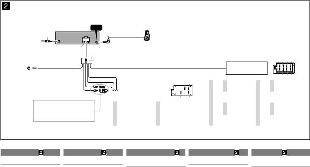
•Connections
•AEP, UK, Italian model
*1 from car antenna (aerial) |
|
von Autoantenne |
|
de l’antenne de la voiture |
|
dall’antenna dell’auto |
|
van een auto-antenne |
|
|
Light blue |
|
Hellblau |
|
Bleu ciel |
ATT |
Azzurro |
Lichtblauw |
*1 |
Note for the antenna (aerial) connecting *1 |
Hinweis zum Anschließen der Antenne |
*1 |
Remarque sur le raccordement de |
*1 |
Nota per il collegamento dell’antenna |
*1 |
Opmerking bij de antenne-aansluiting |
|
If your car antenna (aerial) is an |
Wenn Ihre Autoantenne der ISO-Norm |
|
l’antenne |
|
Se l’antenna dell’auto è di tipo |
|
Indien uw auto is uitgerust met een |
|
ISO (International Organization for |
(Internationale Normungsgemeinschaft) |
|
Si votre antenne de voiture est de type |
|
ISO (International Organization for |
|
antenne van het type ISO (International |
|
Standardization) type, use the supplied |
entspricht, schließen Sie sie mithilfe des |
|
ISO (Organisation internationale de |
|
Standardization), utilizzare l’adattatore |
|
Organization for Standardization), |
|
adaptor to connect it. First connect |
mitgelieferten Adapters an. Verbinden |
|
normalisation), utilisez l’adaptateur fourni |
|
in dotazione per collegarla. Collegare |
|
moet u die aansluiten met behulp |
|
the car antenna (aerial) to the supplied |
Sie zuerst die Autoantenne mit dem |
|
pour la raccorder. Raccordez d’abord |
|
prima l’antenna della macchina |
|
van de bijgeleverde adapter . Sluit |
|
adaptor, then connect it to the antenna |
mitgelieferten Adapter und verbinden Sie |
|
l’antenne de voiture à l’adaptateur fourni |
|
all’adattatore in dotazione, quindi |
|
eerst de auto-antenne aan op de |
|
(aerial) jack of the master unit. |
diesen dann mit der Antennenbuchse |
|
et, ensuite, à la prise d’antenne de |
|
collegarla alla presa dell’antenna |
|
bijgeleverde adapter en vervolgens de |
*2 |
Insert with the cord upwards. |
des Hauptgeräts. |
|
l’appareil principal. |
|
dell’apparecchio principale. |
|
antennestekker op het hoofdtoestel. |
|
*2 |
Mit dem Kabel nach oben einsetzen. |
*2 |
Insérez avec le câble vers le haut. |
*2 |
Inserire con il cavo rivolto verso l’alto. |
*2 |
Plaatsen met het snoer naar boven. |
REMOTE
IN
*2
Fuse (10 A) |
Sicherung (10 A) |
Fusible (10 A) |
Fusibile (10 A) |
Zekering (10 A) |
|
1 |
3 |
5 |
7 |
from the car’s speaker connector
vom Lautsprecheranschluss des Fahrzeugs du connecteur de haut-parleur de la voiture dal connettore dei diffusori dell’auto
van de autoluidsprekeraansluiting
See “Power connection diagram” on the reverse side for details.
Näheres dazu finden Sie im „Stromanschlussdiagramm“. Blättern Sie dazu bitte um.
Voir le « Schéma de raccordement d’alimentation » au verso pour plus de détails.
Per ulteriori informazioni, vedere “Diagramma dei collegamenti di alimentazione” che si trova sul retro.
Zie "Voedingsaansluitschema" op de achterkant voor meer details.
|
|
|
|
|
|
|
|
|
5 |
7 |
|
|
|
|
|
from the car’s power connector |
|
|
|
|
|
|
|
|
|
|
|
|
vom Stromanschluss des Fahrzeugs |
|
|
|
|
|
|
|
||
|
|
|
du connecteur d’alimentation de la voiture |
|
|
|
|
|
|
|||
|
|
|
dal connettore di alimentazione dell’auto |
|
|
|
|
|
|
|||
|
|
|
van de autovoedingsaansluiting |
|
|
|
|
|
|
4 |
8 |
|
|
|
|
|
|
|
|
|
|
|
|||
|
|
|
|
|
|
|
|
|
|
|||
|
|
|
|
|
|
|
|
|
|
|||
|
|
Yellow |
continuous power supply |
|
|
Red |
|
|
switched power supply |
|||
|
|
Gelb |
permanente Stromversorgung |
|
|
Rot |
|
geschaltete Stromversorgung |
||||
|
4 |
Jaune |
alimentation continue |
7 |
|
Rouge |
|
|
alimentation commutée |
|||
|
|
Giallo |
alimentazione continua |
|
|
Rosso |
|
|
alimentazione commutata |
|||
|
|
Geel |
continu voeding |
|
|
Rood |
|
|
geschakelde voeding |
|||
|
|
|
|
|
|
|
|
|
|
|||
|
|
Blue |
power antenna (aerial) control |
|
|
Black |
|
|
ground (earth) |
|||
|
|
Blau |
Motorantennensteuerung |
|
|
Schwarz |
|
|
Masse |
|
|
|
|
5 |
Bleu |
antenne électrique |
8 |
|
Noir |
|
|
masse |
|
|
|
|
|
Blu |
comando dell’antenna elettrica |
|
|
Nero |
|
|
terra |
|
|
|
|
|
Blauw |
elektrische antenne |
|
|
Zwart |
|
|
aarding |
|
|
|
Positions 1, 2, 3, and 6 do not have pins.
An Position 1, 2, 3 und 6 befinden sich keine Stifte.
Les positions 1, 2, 3 et 6 ne comportent pas de broches.
Le posizioni 1, 2, 3 e 6 non hanno piedini.
De posities 1, 2, 3 en 6 hebben geen pins.
|
|
|
|
|
|
|
2 |
4 |
6 |
8 |
|
|
|
|
|
|
|
|
|
||
|
|
|
Speaker, Rear, Right |
|
|
|
|
Speaker, Front, Left |
||
1 |
|
|
Lautsprecher hinten rechts |
|
|
|
Lautsprecher vorne links |
|||
Purple |
+ |
Haut-parleur, arrière, droit |
5 |
White |
+ |
Haut-parleur, avant, gauche |
||||
|
|
Diffusore, posteriore, destro |
|
|
Diffusore, anteriore, sinistro |
|||||
|
Violett |
|
Luidspreker, achter, rechts |
|
Weiß |
|
Luidspreker, voor, links |
|||
|
Violet |
|
Speaker, Rear, Right |
|
Blanc |
|
|
Speaker, Front, Left |
||
|
Viola |
|
|
Bianco |
|
|
||||
2 |
Paars |
– |
Lautsprecher hinten rechts |
6 |
Wit |
– |
Lautsprecher vorne links |
|||
|
Haut-parleur, arrière, droit |
|
Haut-parleur, avant, gauche |
|||||||
|
|
|
Diffusore, posteriore, destro |
|
|
|
Diffusore, anteriore, sinistro |
|||
|
|
|
Luidspreker, achter, rechts |
|
|
|
Luidspreker, voor, links |
|||
|
|
|
Speaker, Front, Right |
|
|
|
|
Speaker, Rear, Left |
||
3 |
|
|
Lautsprecher vorne rechts |
|
|
|
Lautsprecher hinten links |
|||
Gray |
+ |
Haut-parleur, avant, droit |
7 |
Green |
+ |
Haut-parleur, arrière, gauche |
||||
|
|
Diffusore, anteriore, destro |
|
|
Diffusore, posteriore, sinistro |
|||||
|
Grau |
|
Luidspreker, voor, rechts |
|
Grün |
|
Luidspreker, achter, links |
|||
|
Gris |
|
|
|
Vert |
|
|
|
|
|
|
|
Speaker, Front, Right |
|
|
|
Speaker, Rear, Left |
||||
|
Grigio |
|
|
Verde |
|
|
||||
|
Grijs |
|
Lautsprecher vorne rechts |
|
Groen |
|
Lautsprecher hinten links |
|||
4 |
|
– |
Haut-parleur, avant, droit |
8 |
|
– |
Haut-parleur, arrière, gauche |
|||
|
|
|
Diffusore, anteriore, destro |
|
|
|
Diffusore, posteriore, sinistro |
|||
|
|
|
Luidspreker, voor, rechts |
|
|
|
Luidspreker, achter, links |
|||
Negative polarity positions 2, 4, 6, and 8 have striped leads.
An den negativ gepolten Positionen 2, 4, 6 und 8 befinden sich gestreifte Adern.
Les positions de polarité négative 2, 4, 6 et 8 sont dotées de cordons rayés.
Le posizioni a polarità negativa 2, 4, 6 e 8 hanno cavi rigati.
De posities voor negatieve polariteit (2, 4, 6 en 8) hebben gestreepte kabels.
Connection diagram |
Anschlussdiagramm |
Schémas de raccordement |
Schema di collegamento |
Aansluitschema |
To the interface cable of a car telephone
Warning
If you have a power antenna (aerial) without a relay box, connecting this unit with the supplied power connecting lead may damage the antenna (aerial).
Notes on the control and power supply leads
•The power antenna (aerial) control lead (blue) supplies +12 V DC when you turn on the tuner, or when you activate the AF (Alternative Frequency) or TA (Traffic Announcement) function.
•When your car has built-in FM/MW/LW antenna (aerial) in the rear/side glass, connect the power antenna (aerial) control lead (blue) or the accessory power supply lead (red) to the power terminal of the existing antenna (aerial) booster. For details, consult your dealer.
•A power antenna (aerial) without a relay box cannot be used with this unit.
Memory hold connection
When the yellow power supply lead is connected, power will always be supplied to the memory circuit even when the ignition switch is turned off.
Notes on speaker connection
•Before connecting the speakers, turn the unit off.
•Use speakers with an impedance of 4 to 8 ohms, and with adequate power handling capacities to avoid its damage.
•Do not connect the speaker terminals to the car chassis, or connect the terminals of the right speakers with those of the left speaker.
•Do not connect the ground (earth) lead of this unit to the negative (–) terminal of the speaker.
•Do not attempt to connect the speakers in parallel.
•Connect only passive speakers. Connecting active speakers (with built-in amplifiers) to the speaker terminals may damage the unit.
•To avoid a malfunction, do not use the built-in speaker leads installed in your car if the unit shares a common negative (–) lead for the right and left speakers.
•Do not connect the unit’s speaker leads to each other.
Note on connection
If speaker and amplifier are not connected correctly, “FAILURE” appears in the display. In this case, make sure the speaker and amplifier are connected correctly.
An Schnittstellenkabel eines Autotelefons
Warnung
Wenn Sie eine Motorantenne ohne Relaiskästchen verwenden, kann durch Anschließen dieses Geräts mit dem mitgelieferten Stromversorgungskabel die Antenne beschädigt werden.
Hinweise zu den Steuerund Stromversorgungsleitungen
•Die Motorantennen-Steuerleitung (blau) liefert +12 V Gleichstrom, wenn Sie den Tuner einschalten oder die AF- (Alternativfrequenzen) oder die TA-Funktion (Verkehrsdurchsagen) aktivieren.
•Wenn das Fahrzeug mit einer in der Heck-/ Seitenfensterscheibe integrierten FM (UKW)/MW/LWAntenne ausgestattet ist, schließen Sie die MotorantennenSteuerleitung (blau) oder die Zubehörstromversorgungsleitung (rot) an den Stromversorgungsanschluss des vorhandenen Antennenverstärkers an. Näheres dazu erfahren Sie bei Ihrem Händler.
•Es kann nur eine Motorantenne mit Relaiskästchen angeschlossen werden.
Stromversorgung des Speichers
Wenn die gelbe Stromversorgungsleitung angeschlossen ist, wird der Speicher stets (auch bei ausgeschalteter Zündung) mit Strom versorgt.
Hinweise zum Lautsprecheranschluss
•Schalten Sie das Gerät aus, bevor Sie die Lautsprecher anschließen.
•Verwenden Sie Lautsprecher mit einer Impedanz zwischen 4 und 8 Ohm und ausreichender Belastbarkeit. Ansonsten können die Lautsprecher beschädigt werden.
•Verbinden Sie die Lautsprecheranschlüsse nicht mit dem Wagenchassis und verbinden Sie auch nicht die Anschlüsse des rechten mit denen des linken Lautsprechers.
•Verbinden Sie die Masseleitung dieses Geräts nicht mit dem negativen (–) Lautsprecheranschluss.
•Versuchen Sie nicht, Lautsprecher parallel anzuschließen.
•An die Lautsprecheranschlüsse dieses Geräts dürfen nur Passivlautsprecher angeschlossen werden. Schließen Sie keine Aktivlautsprecher (Lautsprecher mit eingebauten Verstärkern) an, da das Gerät sonst beschädigt werden könnte.
•Um Fehlfunktionen zu vermeiden, verwenden Sie nicht die im Fahrzeug installierten, integrierten Lautsprecherleitungen,
wenn am Ende eine gemeinsame negative (–) Leitung für den rechten und den linken Lautsprecher verwendet wird.
•Verbinden Sie nicht die Lautsprecherkabel des Geräts miteinander.
Hinweis zum Anschließen
Wenn die Lautsprecher nicht richtig angeschlossen sind, erscheint „FAILURE“ im Display. Vergewissern Sie sich in diesem Fall, dass die Lautsprecher richtig angeschlossen sind.
Vers le cordon de liaison d’un téléphone de voiture
Avertissement
Si vous disposez d’une antenne électrique sans boîtier de relais, le branchement de cet appareil au moyen du cordon d’alimentation fourni risque d’endommager l’antenne.
Remarques sur les câbles de commande et d’alimentation
•Le câble de commande (bleu) fournit du courant continu de +12 V lorsque vous mettez le tuner sous tension ou lorsque vous activez la fonction AF (fréquence alternative) ou TA (messages de radioguidage).
•Lorsque votre voiture est équipée d’une antenne FM/MW (GO)/LW (PO) intégrée dans la vitre arrière/latérale, raccordez le câble de commande d’antenne (bleu) ou le câble d’alimentation des accessoires (rouge) à la borne d’alimentation de l’amplificateur d’antenne existant. Pour plus de détails, consultez votre revendeur.
•Une antenne électrique sans boîtier de relais ne peut pas être utilisée avec cet appareil.
Raccordement pour la conservation de la mémoire
Lorsque le câble d’alimentation jaune est connecté, le circuit de la mémoire est alimenté en permanence même si la clé de contact est en position d’arrêt.
Remarques sur le raccordement des haut-parleurs
•Avant de raccorder les haut-parleurs, mettez l’appareil hors tension.
•Utilisez des haut-parleurs ayant une impédance de 4 à 8 ohms et une capacité adéquate sous peine de les endommager.
•Ne raccordez pas les bornes du système de haut-parleurs au châssis de la voiture et ne pas connecter les bornes du hautparleur droit à celles du haut-parleur gauche.
•Ne raccordez pas le câble de mise à la masse de cet appareil à la borne négative (–) du haut-parleur.
•Ne tentez pas de raccorder les haut-parleurs en parallèle.
•Connectez uniquement des haut-parleurs passifs. Le raccordement de haut-parleurs actifs (avec des amplificateurs intégrés) aux bornes des haut-parleurs pourrait endommager l’appareil.
•Pour éviter tout problème de fonctionnement, n’utilisez pas les câbles des haut-parleurs intégrés installés dans votre voiture si l’appareil dispose d’un câble négatif commun (–) pour les haut-parleurs droit et gauche.
•Ne raccordez pas entre eux les cordons des haut-parleurs de l’appareil.
Remarque sur le raccordement
Si le haut-parleur et l’amplificateur ne sont pas raccordés correctement, le message « FAILURE » s’affiche. Dans ce cas, assurez-vous que le haut-parleur et l’amplificateur sont raccordés correctement.
Al cavo di interfaccia di un telefono per auto
Avvertenza
Quando si collega l’apparecchio con il cavo di alimentazione in dotazione , si potrebbe danneggiare l’antenna elettrica se questa non dispone di scatola a relè.
Note sui cavi di controllo e di alimentazione
•Il cavo (blu) di controllo dell’antenna elettrica fornisce alimentazione pari a +12 V CC quando si attiva il sintonizzatore oppure la funzione TA (notiziario sul traffico) o AF (frequenza alternativa).
•Se l’automobile è dotata di antenna FM/MW/LW incorporata nel vetro posteriore/laterale, collegare il cavo (blu) di controllo dell’antenna elettrica o il cavo (rosso) di ingresso dell’alimentazione ausiliaria al terminale di alimentazione
dell’amplificatore di potenza dell’antenna esistente. Per ulteriori informazioni, consultare il proprio fornitore.
•Non è possibile usare un’antenna elettrica senza scatola a relè con questo apparecchio.
Collegamento per la conservazione della memoria
Quando il cavo di alimentazione giallo è collegato, viene sempre fornita alimentazione al circuito di memoria anche quando l’interruttore di accensione è spento.
Note sul collegamento dei diffusori
•Prima di collegare i diffusori spegnere l’apparecchio.
•Usare diffusori di impedenza compresa tra 4 e 8 ohm e con capacità di potenza adeguata, altrimenti i diffusori potrebbero venire danneggiati.
•Non collegare i terminali del sistema diffusori al telaio dell’auto e non collegare i terminali del diffusore destro a quelli del diffusore sinistro.
•Non collegare il cavo di terra di questo apparecchio al terminale negativo (–) del diffusore.
•Non collegare i diffusori in parallelo.
•Assicurarsi di collegare soltanto diffusori passivi, poiché il collegamento di diffusori attivi, dotati di amplificatori
incorporati, ai terminali dei diffusori potrebbe danneggiare l’apparecchio.
•Per evitare problemi di funzionamento, non utilizzare i cavi dei diffusori incorporati installati nell’automobile se l’apparecchio condivide un cavo comune negativo (–) per i diffusori destro e sinistro.
•Non collegare fra loro i cavi dei diffusori dell’apparecchio.
Nota sui collegamenti
Se il diffusore non è collegato correttamente, “FAILURE” viene visualizzato nel display. In tal caso, accertarsi che il diffusore sia collegato correttamente.
Naar het interface-snoer van een autotelefoon
Waarschuwing
Indien u een elektrische antenne hebt zonder relaiskast, kan het aansluiten van dit apparaat met de bijgeleverde voedingskabel de antenne beschadigen.
Opmerkingen over de bedieningsen voedingskabels
•De bedieningskabel van de elektrische antenne (blauw) levert +12 V gelijkstroom wanneer u de tuner inschakelt of de AF (alternatieve frequenties) of TA (verkeersinformatie) functie activeert.
•Wanneer uw auto is uitgerust met een FM/MW/LW-antenne in de achterruit/zijruit, moet u de bedieningskabel van de elektrische antenne (blauw) of de voedingskabel van de accessoires (rood) aansluiten op de voedingsingang van de
bestaande antenneversterker. Raadpleeg uw dealer voor meer details.
•Met dit apparaat is het niet mogelijk een elektrische antenne zonder relaiskast te gebruiken.
Instandhouden van het geheugen
Zolang de gele voedingskabel is aangesloten, blijft de stroomvoorziening van het geheugen intact, ook wanneer de contactschakelaar van de auto wordt uitgeschakeld.
Opmerkingen betreffende het aansluiten van de luidsprekers
•Zorg dat het apparaat is uitgeschakeld, alvorens de luidsprekers aan te sluiten.
•Gebruik luidsprekers met een impedantie van 4 tot 8 Ohm en let op dat die het vermogen van de versterker kunnen verwerken. Als u dit niet doet, kunnen de luidsprekers ernstig beschadigd raken.
•Verbind in geen geval de aardingskabel van de luidsprekers met het chassis van de auto en sluit de aansluitingen van de rechteren linkerluidspreker niet op elkaar aan.
•Verbind de aarddraad van dit apparaat niet met de negatieve
(–) aansluiting van de luidspreker.
•Probeer nooit de luidsprekers parallel aan te sluiten.
•Sluit geen actieve luidsprekers (met ingebouwde versterkers) aan op de luidsprekeraansluiting van dit apparaat. Dit zal leiden tot beschadiging van de actieve luidsprekers. Sluit dus altijd uitsluitend luidsprekers zonder ingebouwde versterker aan.
•Om defecten te vermijden mag u de bestaande luidsprekerbedrading in uw auto niet gebruiken wanneer er een gemeenschappelijke negatieve (–) kabel is voor de rechteren linkerluidsprekers.
•Verbind de luidsprekerkabels niet met elkaar.
Opmerking over aansluiten
Als de luidspreker en versterker niet goed zijn aangesloten, wordt "FAILURE" in het display weergegeven. In dit geval moet u zorgen dat de luidspreker en versterker correct zijn aangesloten.
7
CDX-GT33U
• Russian model
*1 ɉɪɢɦɟɱɚɧɢɟ ɨ ɩɨɞɫɨɟɞɢɧɟɧɢɢ ɚɧɬɟɧɧɵ |
*1 ɉɪɢɦɿɬɤɚ ɞɨ ɩɿɞɤɥɸɱɟɧɧɹ ɪɚɞɿɨɚɧɬɟɧɢ |
ȿɫɥɢ ɚɧɬɟɧɧɚ ɜ ȼɚɲɟɦ ɚɜɬɨɦɨɛɢɥɟ |
əɤɳɨ ɚɜɬɨɦɨɛɿɥɶɧɚ ɪɚɞɿɨɚɧɬɟɧɚ ɧɚɥɟɠɢɬɶ |
ɨɬɧɨɫɢɬɫɹ ɤ ɬɢɩɭ, ɭɬɜɟɪɠɞɟɧɧɨɦɭ ISO |
ɞɨ ɬɢɩɭ ISO (Ɇɿɠɧɚɪɨɞɧɚ ɨɪɝɚɧɿɡɚɰɿɹ |
(Ɇɟɠɞɭɧɚɪɨɞɧɨɣ ɨɪɝɚɧɢɡɚɰɢɟɣ ɩɨ |
ɡɿ ɫɬɚɧɞɚɪɬɢɡɚɰɿʀ), ɞɥɹ ʀʀ ɩɿɞɤɥɸɱɟɧɧɹ |
ɫɬɚɧɞɚɪɬɢɡɚɰɢɢ), ɢɫɩɨɥɶɡɭɣɬɟ ɞɥɹ ɟɟ |
ɜɢɤɨɪɢɫɬɨɜɭɣɬɟ ɚɞɚɩɬɟɪ . ɋɩɨɱɚɬɤɭ |
ɩɨɞɫɨɟɞɢɧɟɧɢɹ ɩɟɪɟɯɨɞɧɢɤ . ɋɧɚɱɚɥɚ |
ɩɿɞɤɥɸɱɿɬɶ ɚɜɬɨɦɨɛɿɥɶɧɭ ɚɧɬɟɧɭ ɞɨ |
ɩɨɞɫɨɟɞɢɧɢɬɟ ɚɜɬɨɦɨɛɢɥɶɧɭɸ ɚɧɬɟɧɧɭ |
ɚɞɚɩɬɟɪɚ ɡ ɤɨɦɩɥɟɤɬɭ, ɚ ɩɨɬɿɦ ɩɿɞɤɥɸɱɿɬɶ ʀʀ |
ɤ ɩɪɢɥɚɝɚɟɦɨɦɭ ɩɟɪɟɯɨɞɧɢɤɭ, ɚ ɡɚɬɟɦ ɤ |
ɞɨ ɝɧɿɡɞɚ ɚɧɬɟɧɢ ɜ ɝɨɥɨɜɧɨɦɭ ɩɪɢɫɬɪɨʀ. |
ɚɧɬɟɧɧɨɦɭ ɝɧɟɡɞɭ ɚɩɩɚɪɚɬɚ. |
*2 ȼɫɬɚɜɬɟ ɲɧɭɪɨɦ ɞɨɝɨɪɢ. |
*2 ȼɫɬɚɜɥɹɟɬɫɹ ɩɪɨɜɨɞɨɦ ɜɜɟɪɯ. |
|
REMOTE
IN
*2
*1 ɨɬ ɚɜɬɨɦɨɛɢɥɶɧɨɣ ɚɧɬɟɧɧɵ
ɜɿɞ ɚɜɬɨɦɨɛɿɥɶɧɨʀ ɪɚɞɿɨɚɧɬɟɧɢ
ɉɪɟɞɨɯɪɚɧɢɬɟɥɶ (10 Ⱥ) Ɂɚɩɨɛɿɠɧɢɤ (10 A)
1 |
Ɏɢɨɥɟɬɨɜɵɣ |
+ |
Ƚɪɨɦɤɨɝɨɜɨɪɢɬɟɥɶ, ɡɚɞɧɢɣ, ɩɪɚɜɵɣ |
|
|
Ⱦɢɧɚɦɿɤ: ɡɚɞɧɿɣ, ɩɪɚɜɢɣ |
|
2 |
Ɏɿɨɥɟɬɨɜɢɣ |
– |
Ƚɪɨɦɤɨɝɨɜɨɪɢɬɟɥɶ, ɡɚɞɧɢɣ, ɩɪɚɜɵɣ |
|
|
|
Ⱦɢɧɚɦɿɤ: ɡɚɞɧɿɣ, ɩɪɚɜɢɣ |
3 |
ɋɟɪɵɣ |
+ |
Ƚɪɨɦɤɨɝɨɜɨɪɢɬɟɥɶ, ɩɟɪɟɞɧɢɣ, ɩɪɚɜɵɣ |
|
|
Ⱦɢɧɚɦɿɤ: ɩɟɪɟɞɧɿɣ, ɩɪɚɜɢɣ |
|
4 |
ɋɿɪɢɣ |
– |
Ƚɪɨɦɤɨɝɨɜɨɪɢɬɟɥɶ, ɩɟɪɟɞɧɢɣ, ɩɪɚɜɵɣ |
|
|
|
Ⱦɢɧɚɦɿɤ: ɩɟɪɟɞɧɿɣ, ɩɪɚɜɢɣ |
5 |
Ȼɟɥɵɣ |
+ |
Ƚɪɨɦɤɨɝɨɜɨɪɢɬɟɥɶ, ɩɟɪɟɞɧɢɣ, ɥɟɜɵɣ |
|
|
Ⱦɢɧɚɦɿɤ: ɩɟɪɟɞɧɿɣ, ɥɿɜɢɣ |
|
6 |
Ȼɿɥɢɣ |
– |
Ƚɪɨɦɤɨɝɨɜɨɪɢɬɟɥɶ, ɩɟɪɟɞɧɢɣ, ɥɟɜɵɣ |
|
|
|
Ⱦɢɧɚɦɿɤ: ɩɟɪɟɞɧɿɣ, ɥɿɜɢɣ |
7 |
Ɂɟɥɟɧɵɣ |
+ |
Ƚɪɨɦɤɨɝɨɜɨɪɢɬɟɥɶ, ɡɚɞɧɢɣ, ɥɟɜɵɣ |
|
|
Ⱦɢɧɚɦɿɤ: ɡɚɞɧɿɣ, ɥɿɜɢɣ |
|
8 |
Ɂɟɥɟɧɢɣ |
– |
Ƚɪɨɦɤɨɝɨɜɨɪɢɬɟɥɶ, ɡɚɞɧɢɣ, ɥɟɜɵɣ |
|
|
|
Ⱦɢɧɚɦɿɤ: ɡɚɞɧɿɣ, ɥɿɜɢɣ |
ɉɨɡɢɰɢɢ ɨɬɪɢɰɚɬɟɥɶɧɨɣ ɩɨɥɹɪɧɨɫɬɢ 2, 4, 6 ɢ 8 ɢɦɟɸɬ ɩɪɨɜɨɞɚ ɫ ɩɨɥɨɫɤɚɦɢ.
ɉɪɨɜɨɞɤɚ ɞɨ ɩɨɡɢɰɿɣ ɿɡ ɜɿɞ’ɽɦɧɨɸ ɩɨɥɹɪɧɿɫɬɸ 2, 4, 6 ɿ 8
– ɫɦɭɝɚɫɬɚ.
|
|
|
Ƚɨɥɭɛɨɣ |
ATT |
Ȼɥɚɤɢɬɧɢɣ |
1 3 5 7
ɨɬ ɪɚɡɴɟɦɚ ɝɪɨɦɤɨɝɨɜɨɪɢɬɟɥɟɣ ɚɜɬɨɦɨɛɢɥɹ ɜɿɞ ɪɨɡ’ɽɦɭ ɞɢɧɚɦɿɤɚ ɚɜɬɨɦɨɛɿɥɹ
2 |
4 |
6 |
8 |
|
|
5 |
7 |
ɨɬ ɪɚɡɴɟɦɚ ɷɥɟɤɬɪɨɩɢɬɚɧɢɹ ɚɜɬɨɦɨɛɢɥɹ ɜɿɞ ɪɨɡ’ɽɦɭ ɠɢɜɥɟɧɧɹ ɚɜɬɨɦɨɛɿɥɹ
ɉɨɞpɨɛɧee cɦ. ɜ paɡɞeɥe “Cxeɦa ɩɨɞɤɥɸɱeɧɢɹ ɩɢɬaɧɢɹ” ɧa ɨɛpaɬɧɨɣ cɬɨpɨɧe.
Ⱦɥɹ ɨɬɪɢɦɚɧɧɹ ɞɟɬɚɥɶɧɨʀ ɿɧɮɨɪɦɚɰɿʀ ɞɢɜ. “ɋɯɟɦɚ ɩɿɞɤɥɸɱɟɧɧɹ ɠɢɜɥɟɧɧɹ” ɧɚ ɡɜɨɪɨɬɧɨɦɭ ɛɨɰɿ.
|
|
4 |
8 |
|
|
|
|
4 |
ɀɟɥɬɵɣ |
ɧɟɩɪɟɪɵɜɧɨɟ ɩɨɫɬɭɩɥɟɧɢɟ ɩɢɬɚɧɢɹ |
|
ɀɨɜɬɢɣ |
ɬɪɢɜɚɥɟ ɩɨɫɬɚɱɚɧɧɹ ɠɢɜɥɟɧɧɹ |
|
|
|
|
||
|
ɋɢɧɢɣ |
ɚɧɬɟɧɧɚ ɫ ɷɥɟɤɬɪɢɱɟɫɤɢɦ |
|
5 |
ɋɢɧɿɣ |
ɩɪɢɜɨɞɨɦ ɤɟɪɭɜɚɧɧɹ ɚɧɬɟɧɨɸ ɡ |
|
|
|
ɟɥɟɤɬɪɨɩɪɢɜɨɞɨɦ |
|
7 |
Ʉɪɚɫɧɵɣ |
ɢɦɩɭɥɶɫɧɵɣ ɢɫɬɨɱɧɢɤ ɩɢɬɚɧɢɹ |
|
ɑɟɪɜɨɧɢɣ |
ɿɦɩɭɥɶɫɧɟ ɩɨɫɬɚɱɚɧɧɹ ɠɢɜɥɟɧɧɹ |
||
8 |
ɑɟɪɧɵɣ |
ɡɟɦɥɹ |
|
ɑɨɪɧɢɣ |
ɡɚɡɟɦɥɟɧɧɹ |
|
|
|
|
||
ɉɨɡɢɰɢɢ 1, 2, 3 ɢ 6 ɧɟ ɢɦɟɸɬ ɪɚɡɴɟɦɨɜ.
Ⱦɥɹ ɩɨɡɢɰɿɣ 1, 2, 3 ɿ 6 ɧɟɦɚɽ ɤɨɧɬɚɤɬɧɢɯ ɲɬɢɪɤɿɜ.
ɋɯɟɦɚ ɩɨɞɤɥɸɱɟɧɢɹ 

Ʉ ɢɧɬepɮeɣcɧɨɦy ɤaɛeɥɸ aɜɬɨɦɨɛɢɥɶɧɨɝɨ ɬeɥeɮɨɧa
ȼɧɢɦɚɧɢɟ
ȿɫɥɢ ȼɵ ɢɫɩɨɥɶɡɭɟɬɟ ɚɧɬɟɧɧɭ ɫ ɷɥɟɤɬɪɢɱɟɫɤɢɦ ɩɪɢɜɨɞɨɦ ɛɟɡ ɪɟɥɟɣɧɨɝɨ ɛɥɨɤɚ, ɩɨɞɫɨɟɞɢɧɟɧɢɟ ɷɬɨɝɨ ɚɩɩɚɪɚɬɚ ɩɨɫɪɟɞɫɬɜɨɦ ɩɪɢɥɚɝɚɟɦɨɝɨ ɩɪɨɜɨɞɚ ɩɢɬɚɧɢɹ ɦɨɠɟɬ ɩɪɢɜɟɫɬɢ ɤ ɩɨɜɪɟɠɞɟɧɢɸ ɚɧɬɟɧɧɵ.
Ɉ ɩɪɨɜɨɞɚɯ ɭɩɪɚɜɥɟɧɢɹ ɢ ɩɢɬɚɧɢɹ
•ɉɪɢ ɜɤɥɸɱɟɧɢɢ ɬɸɧɟɪɚ, ɚ ɬɚɤɠɟ ɢɫɩɨɥɶɡɨɜɚɧɢɢ ɮɭɧɤɰɢɢ AF (Ⱥɥɶɬɟɪɧɚɬɢɜɧɵɟ ɱɚɫɬɨɬɵ) ɢɥɢTA (ɋɨɨɛɳɟɧɢɹ ɨ ɬɟɤɭɳɟɣ ɫɢɬɭɚɰɢɢ ɧɚ ɞɨɪɨɝɚɯ) ɩɨ ɩɪɨɜɨɞɭ ɭɩɪɚɜɥɟɧɢɹ ɚɧɬɟɧɧɨɣ ɫ ɷɥɟɤɬɪɢɱɟɫɤɢɦ ɩɪɢɜɨɞɨɦ (ɝɨɥɭɛɨɣ) ɩɨɞɚɟɬɫɹ 12 ȼ ɩɨɫɬɨɹɧɧɨɝɨ ɬɨɤɚ.
•Ecɥɢ ɧa ɡaɞɧeɦ/ɛɨɤɨɜɨɦ cɬeɤɥe aɜɬɨɦɨɛɢɥɹ ycɬaɧɨɜɥeɧa ɜcɬpɨeɧɧaɹ aɧɬeɧɧa ɞɢaɩaɡɨɧa FM/MW/LW, ɩɨɞcɨeɞɢɧɢɬe ɩpɨɜɨɞ ɭɩɪɚɜɥɟɧɢɹ ɚɧɬɟɧɧɨɣ ɫ ɷɥɟɤɬɪɢɱɟɫɤɢɦ ɩɪɢɜɨɞɨɦ (cɢɧɢɣ) ɢɥɢ ɩpɨɜɨɞ ɩɢɬaɧɢɹ ɚɩɩɚɪɚɬɚ (ɤpacɧɵɣ) ɤ ɤɥeɦɦe ɩɢɬaɧɢɹ cyɳecɬɜyɸɳeɝɨ ycɢɥɢɬeɥɹ aɧɬeɧɧɵ.ɑɬɨɛɵ ɩɨɥyɱɢɬɶ ɞɨɩɨɥɧɢɬeɥɶɧɵe cɜeɞeɧɢɹ, ɨɛpaɬɢɬecɶ ɤ cɜɨeɦy
ɞɢɥepy.
•Ⱥɧɬɟɧɧɚ ɫ ɷɥɟɤɬɪɢɱɟɫɤɢɦ ɩɪɢɜɨɞɨɦ, ɧɟ ɫɧɚɛɠɟɧɧɚɹ ɪɟɥɟɣɧɵɦ ɛɥɨɤɨɦ, ɫ ɷɬɢɦ ɚɩɩɚɪɚɬɨɦ ɢɫɩɨɥɶɡɨɜɚɬɶɫɹ ɧɟ ɦɨɠɟɬ.
ɉɨɞɫɨɟɞɢɧɟɧɢɟ ɞɥɹ ɩɨɞɞɟɪɠɤɢ ɩɚɦɹɬɢ
Ʉɨɝɞɚ ɤ ɚɩɩɚɪɚɬɭ ɩɨɞɫɨɟɞɢɧɟɧ ɠɟɥɬɵɣ ɷɥɟɤɬɪɢɱɟɫɤɢɣ ɩɪɨɜɨɞ, ɛɥɨɤ ɩɚɦɹɬɢ ɛɭɞɟɬ ɩɨɫɬɨɹɧɧɨ ɩɨɥɭɱɚɬɶ ɩɢɬɚɧɢɟ ɞɚɠɟ ɩɪɢ ɜɵɤɥɸɱɟɧɧɨɦ ɡɚɠɢɝɚɧɢɢ.
ɉɪɢɦɟɱɚɧɢɹ ɨɬɧɨɫɢɬɟɥɶɧɨ ɩɨɞɫɨɟɞɢɧɟɧɢɹ ɝɪɨɦɤɨɝɨɜɨɪɢɬɟɥɟɣ
•ɉɪɟɠɞɟ ɱɟɦ ɩɨɞɫɨɟɞɢɧɹɬɶ ɝɪɨɦɤɨɝɨɜɨɪɢɬɟɥɢ, ɜɵɤɥɸɱɢɬɟ ɚɩɩɚɪɚɬ.
•ɂɫɩɨɥɶɡɭɣɬɟ ɝɪɨɦɤɨɝɨɜɨɪɢɬɟɥɢ ɫ ɩɨɥɧɵɦ ɫɨɩɪɨɬɢɜɥɟɧɢɟɦ 4 - 8 Ɉɦ, ɨɛɥɚɞɚɸɳɢɟ ɫɩɨɫɨɛɧɨɫɬɶɸ ɩɪɢɧɢɦɚɬɶ ɞɨɫɬɚɬɨɱɧɨ ɦɨɳɧɵɣ ɫɢɝɧɚɥ. ȼ ɩɪɨɬɢɜɧɨɦ ɫɥɭɱɚɟ ɨɧɢ ɦɨɝɭɬ ɛɵɬɶ ɩɨɜɪɟɠɞɟɧɵ.
•ɇɟ ɩɨɞɫɨɟɞɢɧɹɣɬɟ ɤɨɧɬɚɤɬɧɵɟ ɝɧɟɡɞɚ ɝɪɨɦɤɨɝɨɜɨɪɢɬɟɥɟɣ
ɤɲɚɫɫɢ ɚɜɬɨɦɨɛɢɥɹ ɢ ɧɟ ɫɨɟɞɢɧɹɣɬɟ ɝɧɟɡɞɚ ɩɪɚɜɨɝɨ ɝɪɨɦɤɨɝɨɜɨɪɢɬɟɥɹ ɫ ɝɧɟɡɞɚɦɢ ɥɟɜɨɝɨ.
•He ɩɨɞɤɥɸɱaɣɬe ɩpɨɜɨɞ ɡaɡeɦɥeɧɢɹ ɚɩɩɚɪɚɬɚ ɤ
ɨɬpɢɰaɬeɥɶɧɨɦy (–) ɤɨɧɬaɤɬy ɝpɨɦɤɨɝɨɜɨpɢɬeɥɹ.
•ɇɟ ɩɵɬɚɣɬɟɫɶ ɩɨɞɫɨɟɞɢɧɢɬɶ ɝɪɨɦɤɨɝɨɜɨɪɢɬɟɥɢ ɩɚɪɚɥɥɟɥɶɧɨ.
•ɉɨɞɫɨɟɞɢɧɹɬɶ ɦɨɠɧɨ ɬɨɥɶɤɨ ɩɚɫɫɢɜɧɵɟ ɝɪɨɦɤɨɝɨɜɨɪɢɬɟɥɢ. ɉɨɞɫɨɟɞɢɧɟɧɢɟ ɚɤɬɢɜɧɵɯ ɝɪɨɦɤɨɝɨɜɨɪɢɬɟɥɟɣ (ɫɨ ɜɫɬɪɨɟɧɧɵɦ ɭɫɢɥɢɬɟɥɟɦ) ɤ ɝɧɟɡɞɚɦ ɞɥɹ ɝɪɨɦɤɨɝɨɜɨɪɢɬɟɥɟɣ ɦɨɠɟɬ ɩɪɢɜɟɫɬɢ ɤ ɩɨɜɪɟɠɞɟɧɢɸ ɚɩɩɚɪɚɬɚ.
•Bɨ ɢɡɛeɠaɧɢe ɧeɩpaɜɢɥɶɧɨɣ paɛɨɬɵ ɚɩɩɚɪɚɬɚ ɧe
ɢcɩɨɥɶɡyɣɬe ɜcɬpɨeɧɧɵe ɜ aɜɬɨɦɨɛɢɥɶ ɩpɨɜɨɞa ɝpɨɦɤɨɝɨɜɨpɢɬeɥeɣ, ecɥɢ ɢɫɩɨɥɶɡɭɟɬɫɹ ɨɛɳɢɣ ɨɬpɢɰaɬeɥɶɧɵɣ ɩpɨɜɨɞ (–) ɞɥɹ ɩpaɜɨɝɨ ɢ ɥeɜɨɝɨ ɝpɨɦɤɨɝɨɜɨpɢɬeɥeɣ.
•He ɩɨɞɫɨɟɞɢɧɹɣɬɟ ɞɪɭɝ ɤ ɞɪɭɝɭ ɩpɨɜɨɞa ɝpɨɦɨɤɨɝɨɜɨpɢɬeɥeɣ ɚɩɩɚɪɚɬɚ.
ɉpɢɦeɱaɧɢe ɨɬɧɨcɢɬeɥɶɧɨ ɩɨɞcɨeɞɢɧeɧɢɹ
Ecɥɢ ɝpɨɦɤɨɝɨɜɨpɢɬeɥɶ ɢ ycɢɥɢɬeɥɶ ɩɨɞcɨeɞɢɧeɧɵ ɧeɩpaɜɢɥɶɧɨ, ɧa ɞɢcɩɥee ɨɬɨɛpaɡɢɬcɹ ɧaɞɩɢcɶ“FAILURE”. B ɷɬɨɦ cɥyɱae ɩpɨɜepɶɬe ɩpaɜɢɥɶɧɨcɬɶ ɩɨɞcɨeɞɢɧeɧɢɹ ɝpɨɦɤɨɝɨɜɨpɢɬeɥɹ ɢ ycɢɥɢɬeɥɹ.
ɋɯɟɦɚ ɩɿɞɤɥɸɱɟɧɧɹ 

Ⱦɥɹ ɿɧɬɟɪɮɟɣɫɧɨɝɨ ɤɚɛɟɥɸ ɬɟɥɟɮɨɧɭ ɜ ɚɜɬɨɦɨɛɿɥɿ
ɍɜɚɝɚ!
əɤɳɨ ɚɧɬɟɧɚ ɡ ɟɥɟɤɬɪɨɩɪɢɜɨɞɨɦ ɧɟ ɦɚɽ ɪɟɥɟɣɧɨʀ ɫɬɿɣɤɢ, ɩɿɞɤɥɸɱɟɧɧɹ ɰɶɨɝɨ ɩɪɢɫɬɪɨɸ ɡɚ ɞɨɩɨɦɨɝɨɸ ɤɚɛɟɥɸ ɠɢɜɥɟɧɧɹ ɡ ɤɨɦɩɥɟɤɬɭ ɦɨɠɟ ɩɨɲɤɨɞɢɬɢ ɚɧɬɟɧɭ.
ɉɪɢɦɿɬɤɚ ɳɨɞɨ ɤɚɛɟɥɸ ɤɟɪɭɜɚɧɧɹ ɬɚ ɤɚɛɟɥɸ ɩɨɫɬɚɱɚɧɧɹ ɠɢɜɥɟɧɧɹ
•Ʉɚɛɟɥɶ ɤɟɪɭɜɚɧɧɹ ɚɧɬɟɧɨɸ ɡ ɟɥɟɤɬɪɨɩɪɢɜɨɞɨɦ (ɫɢɧɿɣ) ɩɨɫɬɚɱɚɽ +12 ȼ ɩɨɫɬɿɣɧɨʀ ɧɚɩɪɭɝɢ ɡɚ ɜɜɿɦɤɧɟɧɧɹ ɬɸɧɟɪɚ ɚɛɨ ɩɿɞ ɱɚɫ ɚɤɬɢɜɚɰɿʀ ɮɭɧɤɰɿʀ AF (Alternative Frequency) (ɚɥɶɬɟɪɧɚɬɢɜɧɚ ɱɚɫɬɨɬɚ) ɚɛɨTA (Traffic Announcement) (ɩɨɜɿɞɨɦɥɟɧɧɹ ɩɪɨ ɫɢɬɭɚɰɿɸ ɧɚ ɞɨɪɨɝɚɯ).
•əɤɳɨ ɜɚɲ ɚɜɬɨɦɨɛɿɥɶ ɨɫɧɚɳɟɧɨ ɜɛɭɞɨɜɚɧɨɸ ɚɧɬɟɧɨɸ FM/MW/LW ɧɚ ɡɚɞɧɶɨɦɭ/ɛɨɤɨɜɨɦɭ ɫɤɥɿ, ɩɿɞɤɥɸɱɿɬɶ ɤɚɛɟɥɶ ɤɟɪɭɜɚɧɧɹ ɚɧɬɟɧɨɸ (ɫɢɧɿɣ) ɚɛɨ ɞɨɞɚɬɤɨɜɢɣ ɤɚɛɟɥɶ ɩɿɞɤɥɸɱɟɧɧɹ ɠɢɜɥɟɧɧɹ (ɱɟɪɜɨɧɢɣ) ɞɨ ɪɨɡ’ɽɦɭ ɠɢɜɥɟɧɧɹ ɧɚɹɜɧɨɝɨ ɚɧɬɟɧɧɨɝɨ ɩɿɞɫɢɥɸɜɚɱɚ. Ⱦɥɹ ɨɬɪɢɦɚɧɧɹ ɞɟɬɚɥɶɧɨʀ ɿɧɮɨɪɦɚɰɿʀ ɡɜɟɪɧɿɬɶɫɹ ɞɨ ɫɜɨɝɨ ɞɢɥɟɪɚ ɡ ɩɪɨɞɚɠɭ.
•Ⱥɧɬɟɧɭ ɡ ɟɥɟɤɬɪɨɩɪɢɜɨɞɨɦ ɛɟɡ ɪɟɥɟɣɧɨʀ ɫɬɿɣɤɢ ɧɟ ɦɨɠɧɚ ɜɢɤɨɪɢɫɬɨɜɭɜɚɬɢ ɿɡ ɰɢɦ ɩɪɢɫɬɪɨɽɦ.
ɉɿɞɤɥɸɱɟɧɧɹ ɡɚɩɚɦ’ɹɬɨɜɭɸɱɨʀ ɫɢɫɬɟɦɢ
əɤɳɨ ɩɿɞɤɥɸɱɟɧɨ ɠɨɜɬɢɣ ɤɚɛɟɥɶ ɩɨɫɬɚɱɚɧɧɹ ɠɢɜɥɟɧɧɹ, ɠɢɜɥɟɧɧɹ ɡɚɜɠɞɢ ɩɨɫɬɚɱɚɬɢɦɟɬɶɫɹ ɞɨ ɡɚɩɚɦ’ɹɬɨɜɭɸɱɨʀ ɫɯɟɦɢ ɧɚɜɿɬɶ ɡɚ ɜɢɦɤɧɟɧɨɝɨ ɡɚɩɚɥɟɧɧɹ.
ɉɪɢɦɿɬɤɚ ɳɨɞɨ ɩɿɞɤɥɸɱɟɧɧɹ ɞɢɧɚɦɿɤɚ
•ɉɟɪɟɞ ɩɿɞɤɥɸɱɟɧɧɹɦ ɞɢɧɚɦɿɤɿɜ ɜɢɦɤɧɿɬɶ ɩɪɢɫɬɪɿɣ.
•ȼɢɤɨɪɢɫɬɨɜɭɣɬɟ ɞɢɧɚɦɿɤɢ ɡ ɩɨɜɧɢɦ ɨɩɨɪɨɦ ɜɿɞ 4 ɞɨ 8 Ɉɦ
ɿɡ ɜɿɞɩɨɜɿɞɧɨɸ ɩɪɢɩɭɫɬɢɦɨɸ ɜɯɿɞɧɨɸ ɩɨɬɭɠɧɿɫɬɸ, ɳɨɛ ɭɧɢɤɧɭɬɢ ʀɯ ɩɨɲɤɨɞɠɟɧɧɹ.
•ɇɟ ɩɿɞɤɥɸɱɚɣɬɟ ɪɨɡ’ɽɦɢ ɞɢɧɚɦɿɤɿɜ ɞɨ ɤɨɪɩɭɫɭ ɚɜɬɨɦɨɛɿɥɹ ɿ ɧɟ ɡ’ɽɞɧɭɣɬɟ ɪɨɡ’ɽɦɢ ɩɪɚɜɨɝɨ ɿ ɥɿɜɨɝɨ ɞɢɧɚɦɿɤɚ.
•ɇɟ ɩɿɞɤɥɸɱɚɣɬɟ ɡɚɡɟɦɥɟɧɢɣ ɤɚɛɟɥɶ ɰɶɨɝɨ ɩɪɢɫɬɪɨɸ ɞɨ ɜɿɞ’ɽɦɧɨɝɨ (–) ɪɨɡ’ɽɦɭ ɞɢɧɚɦɿɤɚ.
•ɇɟ ɧɚɦɚɝɚɣɬɟɫɹ ɩɿɞɤɥɸɱɢɬɢ ɞɢɧɚɦɿɤɢ ɩɚɪɚɥɟɥɶɧɨ.
•ɉɿɞɤɥɸɱɚɣɬɟ ɥɢɲɟ ɩɚɫɢɜɧɿ ɞɢɧɚɦɿɤɢ. ɉɿɞɤɥɸɱɟɧɧɹ ɚɤɬɢɜɧɢɯ ɞɢɧɚɦɿɤɿɜ (ɿɡ ɜɛɭɞɨɜɚɧɢɦ ɩɿɞɫɢɥɸɜɚɱɟɦ) ɞɨ ɪɨɡɧɿɦɿɜ ɞɢɧɚɦɿɤɿɜ ɦɨɠɟ ɩɨɲɤɨɞɢɬɢ ɩɪɢɫɬɪɿɣ.
•ɓɨɛ ɭɧɢɤɧɭɬɢ ɧɟɫɩɪɚɜɧɨʀ ɪɨɛɨɬɢ ɩɪɢɫɬɪɨɸ, ɧɟ ɜɢɤɨɪɢɫɬɨɜɭɣɬɟ ɜɛɭɞɨɜɚɧɢɣ ɤɚɛɟɥɶ ɞɢɧɚɦɿɤɚ, ɜɫɬɚɧɨɜɥɟɧɢɣ ɜ ɚɜɬɨɦɨɛɿɥɿ, ɹɤɳɨ ɩɪɢɫɬɪɿɣ ɜɢɤɨɪɢɫɬɨɜɭɽ ɫɩɿɥɶɧɨ ɧɟɝɚɬɢɜɧɢɣ (–) ɤɚɛɟɥɶ ɞɥɹ ɩɪɚɜɨɝɨ ɬɚ ɥɿɜɨɝɨ ɞɢɧɚɦɿɤɿɜ.
•ɇɟ ɩɿɞɤɥɸɱɚɣɬɟ ɤɚɛɟɥɿ ɞɢɧɚɦɿɤɚ ɩɪɢɫɬɪɨɸ ɨɞɢɧ ɞɨ ɨɞɧɨɝɨ.
ɉɪɢɦɿɬɤɚ ɳɨɞɨ ɩɿɞɤɥɸɱɟɧɧɹ
əɤɳɨ ɞɢɧɚɦɿɤ ɿ ɩɿɞɫɢɥɸɜɚɱ ɧɟ ɩɿɞɤɥɸɱɟɧɨ ɧɚɥɟɠɧɢɦ ɱɢɧɨɦ, ɧɚ ɞɢɫɩɥɟʀ ɜɿɞɨɛɪɚɡɢɬɶɫɹ“FAILURE” (ɩɨɦɢɥɤɚ).ɍ ɬɚɤɨɦɭ ɜɢɩɚɞɤɭ ɩɟɪɟɤɨɧɚɣɬɟɫɹ, ɳɨ ɞɢɧɚɦɿɤ ɿ ɩɿɞɫɢɥɸɜɚɱ ɩɿɞɤɥɸɱɟɧɨ ɧɚɥɟɠɧɢɦ ɱɢɧɨɦ.
8
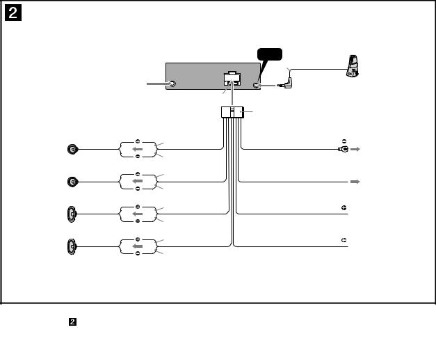
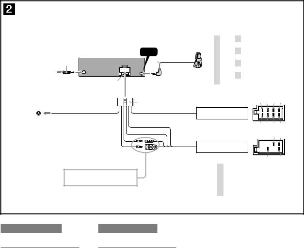
CDX-GT33U
• E, Mexican model
REMOTE
IN
*
from car antenna (aerial) desde la antena del automóvil
Fuse (10 A)
Fusible (10 A)
*Insert with the cord upwards. Insertar con el cable hacia arriba.
|
|
|
White |
Black |
|
Blanco |
Negro |
|
Left |
|
|
Izquierdo |
|
|
White/black striped |
|
|
Con rayas blancas y negras |
|
|
Gray |
Blue |
|
Gris |
||
Azul |
||
Right |
||
|
||
Derecho |
|
|
Gray/black striped |
|
|
Con rayas grises y negras |
|
|
Green |
Red |
|
Verde |
||
Rojo |
||
Left |
||
|
||
Izquierdo |
|
|
Green/black striped |
|
|
Con rayas verdes y negras |
|
|
Purple |
Yellow |
|
Morado |
||
Amarillo |
||
Right |
||
|
||
Derecho |
|
|
Purple/black striped |
|
|
Con rayas moradas y negras |
|
|
|
|
ANT REM |
|
|
Max. supply current 0.1 |
A |
|
Corriente máx. de alimentación de 0,1 |
A |
|


Connection diagram |
|
|
|
Diagrama de conexión |
|
|
|
|
|
|
|
||
To a metal surface of the car |
|
A una superficie metálica del automóvil |
||||
First connect the black ground (earth) lead, then connect the yellow, and red power supply leads.
To the power antenna (aerial) control lead or power supply lead of antenna (aerial) booster amplifier
Notes
•It is not necessary to connect this lead if there is no power antenna (aerial) or antenna (aerial) booster, or with a manually-operated telescopic antenna (aerial).
•When your car has a built-in FM/AM antenna (aerial) in the rear/side glass, see “Notes on the control and power supply leads.”
To the +12 V power terminal which is energized in the accessory position of the ignition key switch
Notes
•If there is no accessory position, connect to the +12 V power (battery) terminal which is energized at all times. Be sure to connect the black ground (earth) lead to a metal surface of the car first.
•When your car has a built-in FM/AM antenna (aerial) in the rear/side glass, see “Notes on the control and power supply leads.”
To the +12 V power terminal which is energized at all times
Be sure to connect the black ground (earth) lead to a metal surface of the car first.
Notes on the control and power supply leads
•The power antenna (aerial) control lead (blue) supplies +12 V DC when you turn on the tuner.
•When your car has built-in FM/AM antenna (aerial) in the rear/ side glass, connect the power antenna (aerial) control lead (blue) or the accessory power supply lead (red) to the power terminal of the existing antenna (aerial) booster. For details, consult your dealer.
•A power antenna (aerial) without a relay box cannot be used with this unit.
Memory hold connection
When the yellow power supply lead is connected, power will always be supplied to the memory circuit even when the ignition switch is turned off.
Notes on speaker connection
•Before connecting the speakers, turn the unit off.
•Use speakers with an impedance of 4 to 8 ohms, and with adequate power handling capacities to avoid its damage.
•Do not connect the speaker terminals to the car chassis, or connect the terminals of the right speakers with those of the left speaker.
•Do not connect the ground (earth) lead of this unit to the negative (–) terminal of the speaker.
•Do not attempt to connect the speakers in parallel.
•Connect only passive speakers. Connecting active speakers (with built-in amplifiers) to the speaker terminals may damage the unit.
•To avoid a malfunction, do not use the built-in speaker leads installed in your car if the unit shares a common negative (–) lead for the right and left speakers.
•Do not connect the unit’s speaker leads to each other.
Note on connection
If speaker and amplifier are not connected correctly, “FAILURE” appears in the display. In this case, make sure the speaker and amplifier are connected correctly.
Conecte primero el cable de conexión a masa negro, y después los cables amarillo y rojo de fuente de alimentación.
Al cable de control de la antena motorizada o al cable de fuente de alimentación del amplificador de señal de la antena
Notas
•Si no se dispone de antena motorizada ni de amplificador de antena, o se utiliza una antena telescópica accionada manualmente, no será necesario conectar este cable.
•Si el automóvil incorpora una antena de FM/AM en el cristal trasero o lateral, consulte “Notas sobre los cables de control y de fuente de alimentación”.
Al terminal de alimentación de +12 V que recibe energía en la posición de accesorio del interruptor de encendido
Notas
•Si no hay posición de accesorio, conéctelo al terminal de alimentación (batería) de +12 V que recibe energía sin interrupción.
Asegúrese de conectar primero el cable de conexión a masa negro a una superficie metálica del automóvil.
•Si el automóvil incorpora una antena de FM/AM en el cristal trasero o lateral, consulte “Notas sobre los cables de control y de fuente de alimentación”.
Al terminal de alimentación de +12 V que recibe energía sin interrupción
Asegúrese de conectar primero el cable de conexión a masa negro a una superficie metálica del automóvil.
Notas sobre los cables de control y de fuente de alimentación
•El cable de control de la antena motorizada (azul) suministrará cc de +12 V cuando conecte la alimentación del sintonizador.
•Si el automóvil dispone de una antena de FM/AM incorporada en el cristal trasero o lateral, conecte el cable de control de antena motorizada (azul) o el cable de fuente de alimentación auxiliar (rojo) al terminal de alimentación del amplificador de antena existente. Para obtener más información, consulte a su distribuidor.
•Con esta unidad no es posible utilizar una antena motorizada sin caja de relé.
Conexión para protección de la memoria
Si conecta el cable de fuente de alimentación amarillo, el circuito de la memoria recibirá siempre alimentación, aunque apague el interruptor de encendido.
Notas sobre la conexión de los altavoces
•Antes de conectar los altavoces, desconecte la alimentación de la unidad.
• Utilice altavoces con una impedancia de 4 a 8 con la capacidad de potencia adecuada para evitar que se dañen.
•No conecte los terminales de altavoz al chasis del automóvil, ni conecte los terminales del altavoz derecho con los del izquierdo.
•No conecte el cable de conexión a masa de esta unidad al terminal negativo (–) del altavoz.
•No intente conectar los altavoces en paralelo.
•Conecte solamente altavoces pasivos. Si conecta altavoces activos (con amplificadores incorporados) a los terminales de altavoz, puede dañar la unidad.
•Para evitar fallas de funcionamiento, no utilice los cables de altavoz incorporados instalados en el automóvil si la unidad comparte un cable negativo común (–) para los altavoces derecho e izquierdo.
•No conecte los cables de altavoz de la unidad entre sí.
Nota sobre la conexión
Si el altavoz y el amplificador no están conectados correctamente, aparecerá “FAILURE” en la pantalla. Si es así, compruebe la conexión de ambos dispositivos.
9

CDX-GT33U
SECTION 3
DISASSEMBLY
•This set can be disassembled in the order shown below.
|
|
|
|
|
|
|
|
|
|
|
|
|
|
|
|
|
|
SET |
|
|
|
|
|
|
|
|
|
|
|
|
|
|
|
|
|
|
|
|
|
|
|
|
|
|
|
|
|
|
|
|
|
|
|
|
|
|
|
||
|
|
|
|
|
|
|
|
|
|
|
|
|||
|
|
|
|
|
|
|
|
|
|
|
|
|
|
|
|
3-1. |
SUB PANEL ASSY |
|
|
|
|
|
|
|
|||||
|
|
|
(Page 11) |
|
|
|
|
|
|
|
||||
|
|
|
|
|
|
|
|
|
|
|
|
|||
|
|
|
|
|
|
|
|
|
|
|
|
|||
|
|
|
|
|
|
|
|
|
|
|
|
|
|
|
|
3-2. |
CD MECHANISM BLOCK |
|
|
|
|
|
|
|
|||||
|
|
|
(Page 11) |
|
|
|
|
|
|
|
||||
|
|
|
|
|
|
|
|
|
|
|
|
|||
|
|
|
|
|
|
|
|
|
|
|
||||
|
|
|
|
|
|
|
|
|
|
|
|
|
|
|
|
|
|
|
|
|
|
|
|
|
|
|
|
|
|
|
3-3. |
MAIN BOARD |
|
3-4. |
SERVO BOARD |
|
|
|
||||||
|
|
|
(Page 12) |
|
|
(Page 12) |
|
|
|
|||||
|
|
|
|
|
|
|
|
|
|
|
|
|
|
|
|
|
|
|
|
|
|
|
|
|
|
|
|
|
|
|
|
|
|
|
|
|
|
|
|
|
|
|
|
|
|
|
|
|
|
|
|
|
3-5. |
CHASSIS (T) SUB ASSY |
|
||||
|
|
|
|
|
|
|
|
|
(Page 13) |
|
||||
|
|
|
|
|
|
|
|
|
|
|
|
|
|
|
|
|
|
|
|
|
|
|
|
|
|
|
|
|
|
|
|
|
|
|
|
|
|
|
|
|
|
|
|
|
|
|
|
|
|
|
|
|
3-6. |
ROLLER ARM ASSY |
|
|
|
||
|
|
|
|
|
|
|
|
|
(Page 13) |
|
|
|
||
|
|
|
|
|
|
|
|
|
|
|
|
|
|
|
|
|
|
|
|
|
|
|
|
|
|
|
|
|
|
|
|
|
|
|
|
|
|
|
|
|
|
|||
|
|
|
|
|
|
|
|
3-7. |
CHASSIS (OP) ASSY |
|
||||
|
|
|
|
|
|
|
|
|
(Page 14) |
|
||||
|
|
|
|
|
|
|
|
|
|
|
|
|||
|
|
|
|
|
|
|
|
|
|
|
|
|
||
|
|
|
|
|
|
|
|
|
|
|
|
|||
|
|
|
|
|
|
|
|
3-8. |
CHUCKING ARM SUB ASSY |
|
||||
|
|
|
|
|
|
|
|
|
(Page 14) |
|
||||
|
|
|
|
|
|
|
|
|
|
|
|
|||
|
|
|
|
|
|
|
|
|
|
|
|
|
||
|
|
|
|
|
|
|
|
|
|
|
|
|||
|
|
|
|
|
|
|
|
3-9. |
SLED MOTOR ASSY |
|
|
|||
|
|
|
|
|
|
|
|
|
(Page 15) |
|
|
|||
|
|
|
|
|
|
|
|
|
|
|
|
|||
|
|
|
|
|
|
|
|
|
|
|
|
|||
|
|
|
|
|
|
|
|
|
|
|
||||
|
|
|
|
|
|
|
|
3-10. |
OPTICAL PICK-UP SECTION |
|
||||
|
|
|
|
|
|
|
|
|
(Page 16) |
|
||||
|
|
|
|
|
|
|
|
|
|
|
||||
|
|
|
|
|
|
|
|
|
|
|
|
|||
|
|
|
|
|
|
|
|
|
|
|
||||
|
|
|
|
|
|
|
|
3-11. |
OPTICAL PICK-UP |
|
|
|||
|
|
|
|
|
|
|
|
|
(Page 16) |
|
|
|||
|
|
|
|
|
|
|
|
|
|
|
|
|
|
|
10

CDX-GT33U
Note: Follow the disassembly procedure in the numerical order shown below.
3-1. SUB PANEL ASSY
two claws
two claws
two screws (+PTT 2.6 × 6)
sub panel assy
3-2. CD MECHANISM BLOCK
bracket (CD)
CD mechanism block
two screws (+PTT 2.6 × 4)


screw
(+PTT 2.6 × 6)
CN501 (3P)
CN701
screw
(+PTT 2.6 × 6)
11
CDX-GT33U
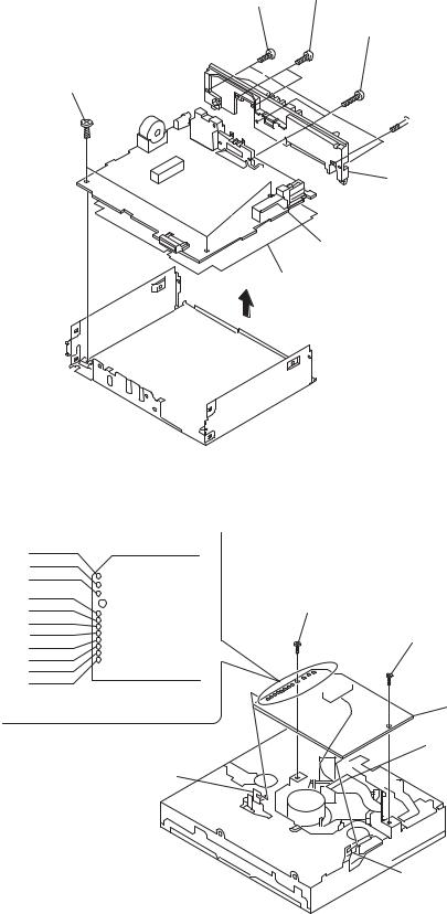
3-3. MAIN BOARD
two screws
(+PTT 2.6 × 8) two screws (+P 2.6 × 8)
two screws (+PTT 2.6 × 10)
three screws (+BTT 2.6 × 5)


 screw
screw
(+PTT 2.6 × 10)
heat sink
MAIN board
insulating sheet
3-4. SERVO BOARD
white red black
white red
black
red orange
blue |
|
yellow |
SERVO board |
gray |
|
Remove the eleven solders.
claw
toothed lock screw (M 1.7 × 2.5)
toothed lock screw (M 1.7 × 2.5)
SERVO board
optical pick-up (16 core) (CN101)
claw
12
 Loading...