


SB91ME
Smeg SB91ME, SX81VJME, SX81VGMA, CX61VGMA1, SA81VGMA User Manual
...
Contents
3
1 INSTRUCTIONS FOR SA
F
E AND PROPER US
E
_
_______________________________
4
2 INSTALLATION OF THE APPLIANCE__________________________________________6
3 ADAPTATION TO DIFFERENT TYPES OF GAS _________________________________9
4 FINAL OPERATIONS______________________________________________________15
5 DESCRIPTION OF FRONT PANEL CONTROLS ________________________________17
6 USE OF THE COOKING HOB _______________________________________________19
7 USE OF THE OVEN_______________________________________________________22
8 ELECTRONIC PROGRAMMER (ONLY ON EQUIPPED MODELS) __________________26
9 DIGITAL TIMER (CERTAIN MODELS ONLY) ___________________________________28
10 ANALOGUE CLOCK (ONLY ON EQUIPPED MODELS) _________________________28
11 CLEANING AND MAINTENANCE ___________________________________________29
12 EXTRAORDINARY MAINTENANCE _________________________________________31
THESE INSTRUCTIONS ARE VALID ONLY FOR END USER COUNTRIES WHOSE IDENTIFICATIO
N
SYMBOLS APPEAR ON THE COVER OF THIS MANUAL.
INSTRUCTIONS FOR THE INSTALLER: these are for the qualified technician who must carry out
a
suitable check of the gas system, install the appliance, set it functioning and carry out an inspection test.
INSTRUCTIONS FOR THE USER: these contain user advice, description of the commands and th
e
correct procedures for cleaning and maintenance of the appliance.

Introduction
4
1 INSTRUCTIONS FOR SAFE AND PROPER USE
THIS MANUAL IS AN INTEGRAL PART OF THE APPLIANCE AND THEREFORE MUST BE KEPT
IN ITS ENTIRETY AND IN AN ACCESSIBLE PLACE FOR THE WHOLE WORKING LIFE OF THE
COOKER. WE ADVISE READING THIS MANUAL AND ALL THE INSTRUCTIONS THEREIN
BEFORE USING THE COOKER. ALSO KEEP THE SERIES OF NOZZLES SUPPLIED.
INSTALLATION MUST BE CARRIED OUT BY QUALIFIED PERSONNEL IN ACCORDANCE WITH
THE REGULATIONS IN FORCE. THIS APPLIANCE IS INTENDED FOR DOMESTIC USES AND
CONFORMS TO CURRENT REGULATIONS IN FORCE. THE APPLIANCE HAS BEEN BUILT TO
CARRY OUT THE FOLLOWING FUNCTIONS: COOKING AND HEATING-UP OF FOOD. ALL
OTHER USES ARE CONSIDERED IMPROPER.
THE MANUFACTURER DECLINES ALL RESPONSIBILITY FOR IMPROPER USE.
DO NOT LEAVE THE PACKING IN THE HOME ENVIRONMENT. SEPARATE THE VARIOUS
WASTE MATERIALS AND TAKE THEM TO THE NEAREST SPECIAL GARBAGE COLLECTION
CENTRE.
IT IS OBLIGATORY FOR THE ELECTRICAL SYSTEM TO BE GROUNDED ACCORDING TO THE
METHODS REQUIRED BY SAFETY RULES.
WHEN LINKING UP TO MAINS BY PLUG AND SOCKET, MAKE SURE THAT BOTH ARE
COMPATIBLE AND CONNECT BY MEANS OF A POWER CABLE COMPLYING WITH APPLICABLE
REGULATIONS.
THE SOCKET MUST BE ACCESSIBLE AFTER THE APPLIANCE HAS BEEN BUILT IN.
NEVER UNPLUG BY PULLING ON THE CABLE.
IMMEDIATELY AFTER INSTALLATION CARRY OUT A BRIEF INSPECTION TEST OF THE
APPLIANCE, FOLLOWING THE INSTRUCTIONS BELOW. SHOULD THE APPLIANCE NOT
FUNCTION, DISCONNECT IT FROM THE SUPPLY AND CALL THE NEAREST TECHNICAL
ASSISTANCE CENTRE.
NEVER ATTEMPT TO REPAIR THE APPLIANCE.
WHEN NOT IN USE, MAKE SURE THAT THE CONTROL KNOBS ARE IN THE CORRECT (OFF)
POSITION
.
NEVER PUT INFLAMMABLE OBJECTS IN THE OVEN: THEY COULD BE ACCIDENTALLY
LIGHTED AND CAUSE FIRES.
THE I.D. PLATE WITH TECHNICAL DATA, REGISTRATION NUMBER AND BRAND NAME IS
POSITIONED VISIBLY IN THE STORAGE COMPARTMENT.
THE PLATE MUST NOT BE REMOVED.
DO NOT PUT PANS WITHOUT PERFECTLY SMOOTH AND FLAT BOTTOMS ON THE COOKING
HOB GRIDS.
DO NOT USE CONTAINERS OR BROILERS THAT EXTEND BEYOND THE OUTER PERIMETER
OF THE HOB.
Introduction
5
LOWER THE GLASS COVER SLOWLY AND BY HAND.
WARNING: THE GLASS COVER MAY SHATTER IF IT OVERHEATS. SWITCH OFF ALL RINGS
AND WAIT FOR THEM TO COOL DOWN BEFORE CLOSING THE COVER.
DURING USE THE APPLIANCE BECOMES VERY HOT. TAKE CARE NOT TO TOUCH THE
HEATING ELEMENTS INSIDE THE OVEN.
THE APPLIANCE IS DESIGNED FOR USE BY ADULTS. DO NOT ALLOW CHILDREN TO GO
NEAR OR PLAY WITH IT.
WHEN OPERATING THE GRILL ALL ACCESSIBLE PARTS COULD BECOME VERY HOT: KEEP
OUT OF THE WAY OF CHILDREN.
IF THE APPLIANCE IS TO BE POSITIONED ON A PLATFORM IT MUST BE INSTALLED IN SUCH
A WAY AS TO PREVENT IT FROM SLIPPING OFF THE FORMER.
THIS APPLIANCE IS MARKED ACCORDING TO THE EUROPEAN DIRECTIVE 2002/96/EC ON
WASTE ELECTRICAL AND ELECTRONIC EQUIPMENT (WEEE).
THIS GUIDELINE IS THE FRAME OF A EUROPEAN-WIDE VALIDITY OF RETURN AND
RECYCLING ON WASTE ELECTRICAL AND ELECTRONIC EQUIPMENT.
BEFORE THE APPLIANCE IS PUT INTO OPERATION, ALL THE LABELS AND PROTECTIVE
FILMS APPLIED INSIDE OR OUTSIDE MUST BE REMOVED.
The manufacturer declines all responsibility for damage to persons or things caused by non
-
observance of the above prescriptions or by interference with any part of the appliance or by the us
e
of non-original spares.
Instruction for the installer
6
2 INSTALLATION OF THE APPLIANCE
It is the law that all gas appliances are installed by competent persons. Corgi gas installers ar
e
approved to work to safe and satisfactory standards. All gas installation, servicing and repair wor
k
must be in accordance with the gas safety regulations 1984 (installation and use) as amended 1990.
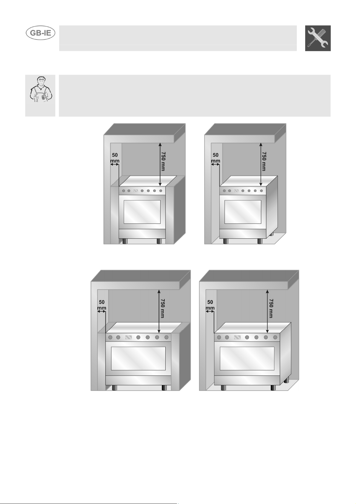
It can be placed against walls higher than the hob, at a distance of at least 50 mm from the side of th
e
appliance, as shown in the drawings A and B relating to the installation classes. Wall units or extracto
r
hoods located above the hob must be at least 750 mm away from it.
A
B
Built-in appliance Free-standing installation
A B
Built-in appliance Free-standing installation
Instruction for the installer
7
2.1 Electrical connection
Make sure that the power line voltage matches the specifications indicated on the rating plate located
inside the storage compartment.
This rating plate must never be removed.
If the appliance is hooked-up to the supply by means of a fixed connection, install a multipolar cut-out
device on the line, with contact opening distance equal to or greater than 3 mm, located near the
appliance and in an easily reachable position.
Hook-up to the supply may be fixed or with plug and socket. In the latter case the plug and socket
must be suitable for the cable employed and conform with the regulations in force. Regardless of the
type of connection, earthing of the appliance is absolutely obligatory. Before connection make sure
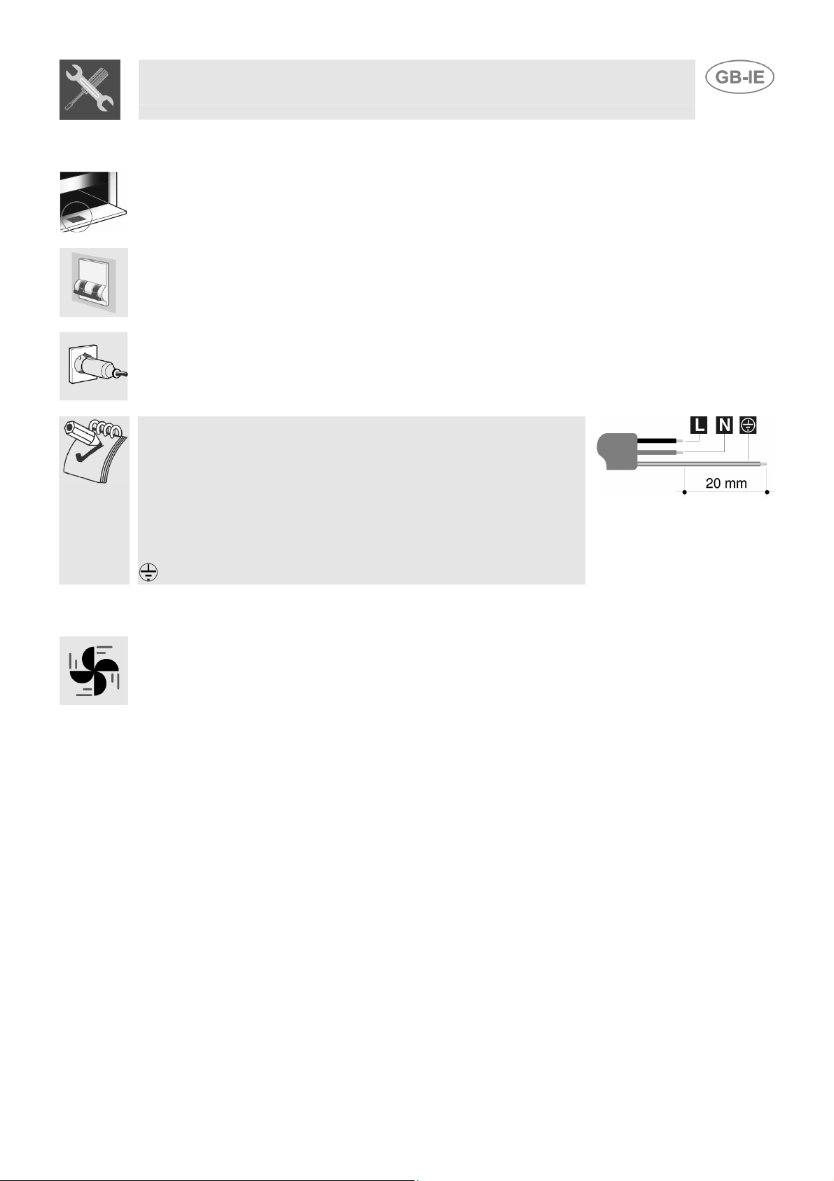
that the supply line is suitably earthed. Avoid the use of reducers, adapters or shunts.1
If the power cable is replaced, the wire section on the new cable must
not be less than 1.5 mm
2
(3 x 1.5 cable), keeping in mind that the end to
be connected to the hob must have the ground wire (yellow-green)
longer by at least 20 mm. Use only H05V2V2-F cable or similar which has
a maximum temperature of 90°C. This must be done by a specialised
technician, who must connect the cooker to the electricity supply
according to the diagram shown here.
L = brown
N = blue
= yellow-green.
2.2 Ventilation requirements
The room containing the appliance should have an air supply in accordance with B.S. 5440 part 2
1989.
1. All rooms require an opening window or equivalent, and some rooms will require a permanent vent
as well.
2. For room volumes up to 5 m
3
an air vent of 100 cm
2
is required.
3. If the room has a door that opens directly to the outside, and the room exceeds 1 m
3
no air vent is
required.
4. For room volumes between 5 m
3 3 2
and 10 m an air vent of 50 cm is required.
5. If there are other fuel burning appliances in the same room B.S. 5440 part 2 1989 should be
consulted to determine the air vent requirements.
6. This appliance must not be installed in a bed sitting room of less than 20 m
3
or in a bathroom o
r
shower room.
Windows and permanent vents should therefore not be blocked or removed without first consulting a
Corgi gas installer.
Failure to install appliances correctly is dangerous and could lead to prosecution.
Instruction for the installer
8
2.3 Connecting to natural and LPG gas
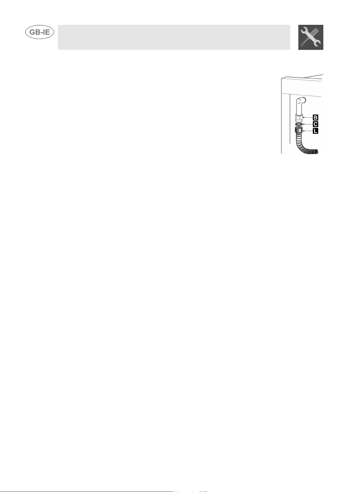
(Please see connection diagram)
Make the connection to the appliance using flexible bayonet style hose in
accordance to B.S. 669. The hose connection at the rear of the appliance has a ½”
BSP internal thread. Please use seal C between the flexible connection L and the
appliance supply tube B. When making the connection, make sure that no stress of
any kind is applied to the cooker and that the hose does not touch any sharp
edges.
If connecting to LPG the bayonet hose must have red bands on it.
Instruction for the installer
9
3 ADAPTATION TO DIFFERENT TYPES OF GAS
Before performing any cleaning or maintenance work, detach the appliance from the electrical socket.
The cooker hob is set for natural gas G20 (2H) at a pressure of 20 mbar for cookers with maxi oven,
and for LPG G30/G31 (3+) at a pressure of 28/37 mbar for cookers with gas-bottle compartments. In
the case of functioning with other types of gas the burner nozzles must be changed and the minimum
flame adjusted on the gas taps. To change the nozzles, proceed as described below.
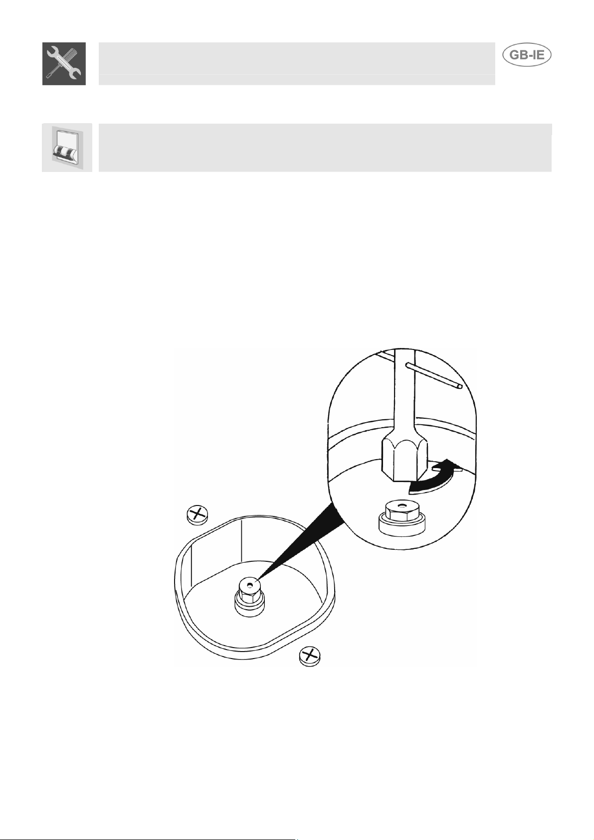
3.1 Replacement of nozzles on the hob
This operation requires no primary air regulation.
1. Extract the grids and remove all the caps and flame-spreader crowns;
2. unscrew the burner nozzles with a 7 mm socket wrench;
3. replace the nozzles according to the type of gas to be used and the description in paragraph “3.2
/
3.3 Burner and nozzle characteristics table”.
4. Replace the burners in the correct position.
Instruction for the installer
10
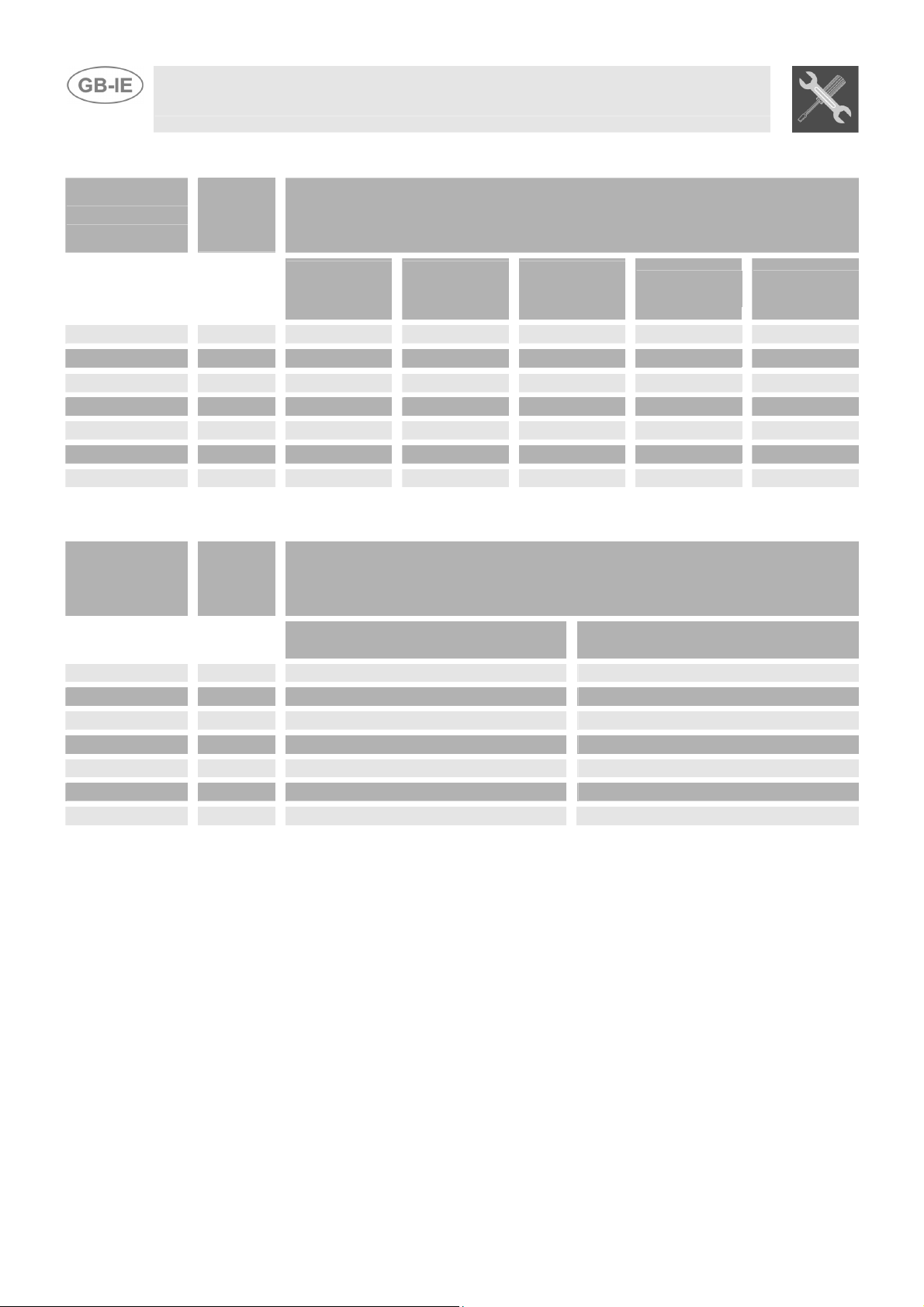
3.2 Burner and nozzle characteristics table (60 cm models)
Burner
Rated
heating
capacity
(kW)
LPG – G30/G31 28/37 mbar
Nozzle
diameter
1/100 mm
By-pass
mm
1/100
Reduced
flowrate
(W)
Flowrate
g/h G30
Flowrate
g/h G31
Auxiliary
1.0 50 30 350 73 71
Semi-rapid
1.75 65 33 450 127 125
Rapid (3)
3.0 85 45 800 218 214
Rapid (5)
2.3 75 45 800 167 164
Triple crown
3.2 91 65 1500 233 229
Oven
3.2 87 48 850 233 229
Grill
2.9 87 // // 218 214
Burner
Rated
heating
capacity
(kW)
NATURAL GAS – G20 20 mbar
Nozzle diameter
1/100 mm
Reduced Flowrate
(W)
Auxiliary
1.0 72 350
Semi-rapid
1.75 97 450
Rapid (3)
3.0 115 800
Rapid (5)
2.3 103 800
Triple crown
3.5 133 1500
Oven
3.2 130 850
Grill
2.9 130 //
Instruction for the installer
11
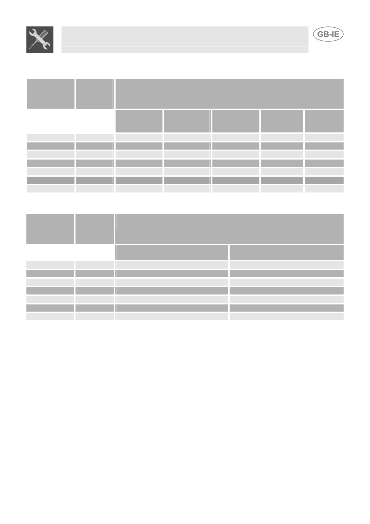
3.3 Burner and nozzle characteristics table (80 cm models)
Burner
Rated
heating
capacity
(kW)
LPG – G30/G31 28/37 mbar
Nozzle
diameter
1/100 mm
By-pass
mm
1/100
Reduced
Flowrate
(W)
Flowrate
g/h G30
Flowrate
g/h G31
Auxiliary 1 50 30 350 73 71
Semi-rapid 1.75 65 33 450 127 125
Rapid 2.5 79 45 800 167 164
Triple crown 3.5 94 65 1500 254 250
Oven 3.2 87 48 850 233 229
Maxi oven 4.6 106 59 1200 334 328
Grill 3.7 94 // // 269 264
Burner
Rated
heating
capacity
(kW)
NATURAL GAS – G20 20 mbar
Nozzle diameter
1/100 mm
Reduced Flowrate
(W)
Auxiliary 1 72 350
Semi-rapid 1.75 97 450
Rapid 2.5 108 800
Triple crown 3.5 140 1500
Oven 3.2 130 850
Maxi oven 4.6 155 1200
Grill 3.7 145 //
 Loading...