


Smeg CX91VG, CX61VML-5, CX91VM, CX61G, CA61VM User Manual
...Contents
1INSTRUCTIONS FOR SAFETY AND USE ____________________________________33
2INSTALLING THE APPLIANCE_____________________________________________35
3ADAPTATION TO DIFFERENT TYPES OF GAS _______________________________39
4FINAL OPERATIONS ____________________________________________________44
5DESCRIPTION OF THE CONTROLS ON THE FRONT PANEL____________________46
6USING THE HOB________________________________________________________48
7USING THE OVEN ______________________________________________________51
8ELECTRONIC PROGRAMMER (ONLY ON MODELS WITH THE RELEVANT FUNCTION)5
9DIGITAL TIMER (ONLY ON MODELS WITH THE RELEVANT FUNCTION) __________57
10ANALOGUE CLOCK (ONLY ON MODELS WITH THE RELEVANT FUNCTION) ______57
11CLEANING AND MAINTENANCE ___________________________________________58
12EXTRAORDINARY MAINTENANCE _________________________________________60
 THESE INSTRUCTIONS ARE VALID ONLY FOR THE DESTINATION COUNTRIES WHOSE IDENTIFYING SYMBOLS ARE INCLUDED ON THE COVER OF THIS MANUAL.
INSTRUCTIONS FOR THE INSTALLER: these are intended for the qualified technician who must carry out an adequate inspection of the gas system, install the appliance, set it functioning and test it.
INSTRUCTIONS FOR THE USER: these contain user advice, a description of the commands and the correct procedures for cleaning and maintenance of the appliance.
32
Presentation
1 INSTRUCTIONS FOR SAFETY AND USE
THIS MANUAL IS AN INTEGRAL PART OF THE APPLIANCE. THEREFORE IT MUST BE KEPT IN ITS ENTIRETY AND IN AN ACCESSIBLE PLACE FOR THE WHOLE WORKING LIFE OF THE COOKER. WE ADVISE YOU TO READ THIS MANUAL AND ALL THE INFORMATION IT CONTAINS CAREFULLY BEFORE USING THE COOKER. ALSO KEEP THE SERIES OF NOZZLES PROVIDED. INSTALLATION MUST BE CARRIED OUT BY QUALIFIED PERSONNEL IN ACCORDANCE WITH THE REGULATIONS IN FORCE. THIS APPLIANCE IS INTENDED FOR DOMESTIC USE AND CONFORMS TO THE EEC DIRECTIVES CURRENTLY IN FORCE. THE APPLIANCE HAS BEEN BUILT TO CARRY OUT THE FOLLOWING FUNCTIONS: COOKING AND HEATING UP FOOD; ALL OTHER USES SHOULD BE CONSIDERED UNSUITABLE.
THE MANUFACTURER CANNOT BE HELD LIABLE FOR USES OTHER THAN THOSE INDICATED.
NEVER LEAVE DISCARDED PACKAGING UNATTENDED IN THE HOME.
SEPARATE WASTE PACKAGING MATERIALS BY TYPE AND CONSIGN THEM TO THE NEAREST SORTED COLLECTION CENTRE.
IT IS OBLIGATORY FOR ALL ELECTRICAL SYSTEMS TO BE GROUNDED ACCORDING TO THE METHODS REQUIRED BY SAFETY LEGISLATION.
THE PLUG TO BE CONNECTED TO THE POWER SUPPLY CABLE AND ITS SOCKET MUST BE OF THE SAME TYPE AND CONFORM TO THE REGULATIONS IN FORCE.
THE SOCKET MUST BE ACCESSIBLE AFTER THE APPLIANCE HAS BEEN BUILT-IN.
NEVER UNPLUG BY PULLING ON THE CABLE.
IMMEDIATELY AFTER INSTALLATION, CARRY OUT A QUICK TEST ON THE APPLIANCE FOLLOWING THE INSTRUCTIONS PROVIDED LATER IN THIS MANUAL. SHOULD THE APPLIANCE NOT FUNCTION, DISCONNECT IT FROM THE POWER SUPPLY AND CALL THE NEAREST TECHNICAL SUPPORT CENTRE.
NEVER ATTEMPT TO REPAIR THE APPLIANCE.
ALWAYS CHECK THAT THE CONTROL KNOBS ARE IN THE  (OFF) POSITION WHEN YOU FINISH USING THE APPLIANCE.
NEVER PLACE FLAMMABLE OBJECTS IN THE OVEN: IF IT SHOULD ACCIDENTALLY BE SWITCHED ON, THIS MIGHT CAUSE A FIRE.
THE IDENTIFICATION PLATE WITH THE TECHNICAL DATA, SERIAL NUMBER AND MARK IS IN A VISIBLE POSITION INSIDE THE STORAGE COMPARTMENT.
DO NOT REMOVE THIS PLATE FOR ANY REASON.
NEVER PLACE PANS WITH BOTTOMS WHICH ARE NOT PERFECTLY FLAT AND SMOOTH ON THE HOB RACKS.
NEVER USE PANS OR GRIDDLES WHICH PROJECT BEYOND THE OUTSIDE EDGE OF THE HOB.
HOLD THE GLASS LID WITH YOUR HAND WHILE LOWERING IT. WARNING: THE GLASS LID CAN SPLINTER IF OVERHEATED.
TURN OFF ALL THE BURNERS AND WAIT FOR THEM TO COOL DOWN BEFORE CLOSING IT.
33
Presentation
DURING USE THE APPLIANCE BECOMES VERY HOT. TAKE CARE NEVER TO TOUCH THE HEATING ELEMENTS INSIDE THE OVEN.
THE APPLIANCE IS INTENDED FOR USE BY ADULTS. DO NOT ALLOW CHILDREN TO GO NEAR IT OR PLAY WITH IT.
WHEN THE GRILL IS WORKING THE ACCESSIBLE PARTS CAN BECOME VERY HOT: KEEP CHILDREN AWAY.
IF THE APPLIANCE IS PLACED ON A PEDESTAL, IT MUST BE INSTALLED SO THAT IT CANNOT SLIDE OFF.
IF THE COOKING PRODUCTS ARE INSTALLED ON MOTOR VEHICLES (FOR EXAMPLE, CAMPERS, CARAVANS ETC.) THEY MUST ONLY BE USED WHEN THE VEHICLE IS STOPPED.
INSTALL THE PRODUCT SO THAT WHEN OPENING THE DRAWERS AND DOORS OF UNITS POSITIONED AT THE LEVEL OF THE HOB THERE IS NO POSSIBILITY OF MAKING CONTACT WITH PANS POSITIONED ON TOP OF IT.
THIS APPLIANCE IS MARKED ACCORDING TO EUROPEAN DIRECTIVE 2002/96/EC ON WASTE ELECTRICAL AND ELECTRONIC EQUIPMENT (WEEE).
THIS DIRECTIVE DEFINES THE STANDARDS FOR THE COLLECTION AND RECYCLING OF WASTE ELECTRICAL AND ELECTRONIC EQUIPMENT APPLICABLE THROUGHOUT THE EUROPEAN UNION.
BEFORE THE APPLIANCE IS PUT INTO OPERATION, ALL LABELS AND PROTECTIVE FILMS APPLIED INSIDE OR OUTSIDE MUST BE REMOVED.
The manufacturer cannot be held liable for damage to persons or things caused by failure to comply with the above requirements or by tampering with any part of the appliance or by the use of non-original spare parts.
34

Instructions for the installer
2 INSTALLING THE APPLIANCE
The appliance must be installed by a qualified technician and according to the regulations in force. Depending on the type of installation, it belongs to class 1 (Fig.A) or to class 2, subclass 1 (Fig.B-C). This appliance may be installed next to walls, one of which must be higher than the appliance, at a minimum distance of 50 mm from the side of the appliance, as shown in drawings A and B relative to the installation classes. Any wall cupboards or ventilation hoods must be at a distance of at least 750 mm above the work surface.
A |
B |
Built-in appliance |
Free-standing installation |
A
Built-in appliance
B |
Free-standing installation
C
Appliances equipped with a gas cylinder compartment and electric oven can only be installed as free-standing (see fig. B).
35
Instructions for the installer
2.1Electrical connection
Make sure the voltage and the cross-section of the power supply line match the specifications indicated on the identification plate positioned in the storage compartment.
Do not remove this plate for any reason.
If the appliance is connected to the power supply network by means of a fixed connection, install a multipolar cut-out device on the power supply line, with a contact opening distance equal to or greater than 3 mm, located near the appliance and in an easily reachable position.
Connection to the power supply network may be fixed or with a plug and socket. In the latter case the plug and socket must be suitable for the cable employed and conform to the regulations in force. Regardless of the type of connection, the appliance must be earthed. Before connection, make sure that the power supply line is suitably earthed. Avoid the use of adapters and shunts.
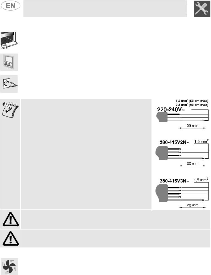
1 - For operation on 220-240V : use a three-pole cable of the H05RR-F or H05V2V2-F type:
3 x 2.5 mm2 (for 90 cm models)
3 x 1.5 mm2 (for 50 and 60 cm models).
2 - For operation on 380-415V2N (only for 90 cm models): use a four-pole cable of the H05RR-F or H05V2V2-F type (cable with a cross-section of 4 x 1.5 mm2)
3 - For operation on 380-415V3N (only for 90 cm models): use a five-pole cable of the H05RR-F or H05V2V2-F type (cable with a cross-section of 5 x 1.5 mm2)
The end to be connected to the appliance must have an earth wire (yellow-green) at least 20 mm longer than the others.
WARNING: THE VALUES INDICATED ABOVE REFER TO THE CROSS-SECTION OF THE INTERNAL CONDUCTOR.
Warning: only some of the 90 cm models can be connected with two or three phases.
2.2Room ventilation
The room containing the appliance should have a permanent air supply in accordance with the standards in force. The room where the appliance is installed must have enough air flow for the regular combustion of gas and for the air exchange needed in the room itself. The air vents, protected by grills, must be suitably dimensioned in compliance with the current regulations and positioned so that no part of them is obstructed.
The cooker must be kept adequately ventilated in order to eliminate the heat and humidity produced by cooking: in particular, after prolonged use, you are recommended to open a window or to increase the speed of any fans.
36

Instructions for the installer
2.3Extraction of the combustion products
The combustion products must be extracted by means of hoods connected to a natural draught chimney whose efficiency is certain or via forced extraction. An efficient extraction system requires precision planning by a specialist qualified in this area and must comply with the positions and distances indicated by the applicable standards. When the job is complete, the installer must issue a certificate of conformity.
2.4Connection to gas
2.4.1Connection with a rubber hose
Installation with a standards-compliant rubber hose must be carried out so that the length of the piping does not exceed 1.5 metres; make sure that the hose does not come into contact with moving parts and that it is not crushed in any way. The inside diameter of the hose must be 8 mm for LIQUID GAS and 13 mm for NATURAL GAS and CITY GAS.
Verify that all the following conditions are met:
•the hose is fixed to the hose connection with safety clamps;
•no part of the hose is in contact with the hot walls (max. 50°C);
•the hose is not under traction or tension and has no tight curves or twists;
•the hose is not in contact with sharp objects or sharp corners;
•if the hose is not perfectly airtight and leaks gas, do not try to repair it: replace it with a new hose;
•verify that the hose is not past its expiry date (serigraphed on the hose itself).
CONNECTION USING RUBBER HOSES COMPLYING WITH THE CURRENT REGULATIONS IS ONLY PERMITTED IF THE HOSE CAN BE INSPECTED ALONG ITS ENTIRE LENGTH.
2.4.2Connection to natural and city gas
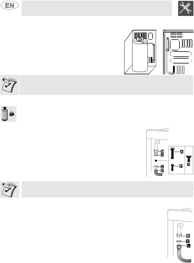
Make the connection to the gas mains using a rubber hose whose specifications comply with the current regulations (verify that the reference standard is stamped on the hose).
Carefully screw the hose connector A to the gas connector B of the appliance, placing the seal C between them. Push the rubber hose D onto the hose connector A and secure it with the clamp E that is compliant with the applicable standard.
37
Instructions for the installer
2.4.3Connection to the gas cylinder in the internal compartment of the appliance (only on
some models)
Open the side compartment and insert a gas cylinder of max. 15 kg. Push one end of the hose onto the hose connector and secure it with one of the two clamps provided. Insert the hose into the gas cylinder compartment via the hole located at the back of the appliance following the diagram shown to the side. Push the other end onto the pressure regulator of the gas cylinder; secure it in place using the second clamp provided. Check for any leaks using a soapy solution, never with a flame.
For the connection between the cooker and the gas cylinder use a piece of standards-compliant hose no less than 1.4 m in length.
2.4.4Connection to liquid gas
Use a standards-compliant pressure regulator and carry out the connection to the gas cylinder in accordance with the regulations in force.
Make sure that the supply pressure complies with the values indicated in the paragraph “3.2/3.3 Burner and nozzle characteristics table”.
Screw the small hose connector F onto the large hose connector A; connect the block thus obtained to the gas connector B (or use the hose connector G which must be connected directly to the gas connector B) and place the seal C in between them. Push the end of the rubber hose H onto the hose connector A+F (or G) and onto the outlet connection of the pressure reducer on the gas cylinder. Secure the end of the hose H to the hose connector A+F (or G) with the standards-compliant clamp I.
The hose connector G illustrated is not supplied with the appliance. Only use standards-compliant hose connectors.
2.4.5Connection with a flexible steel hose (for all types of gas)
This type of connection can be made on both built-in and free-standing appliances. Only use standards-compliant steel hoses whose length is no greater than 2 metres. Screw the end of the flexible hose L onto the threaded ½” external gas connector B (ISO 228-1), with the seal C positioned in between them.
At the end of the installation, check for any leaks with a soapy solution, never with a flame.
38
Instructions for the installer
3 ADAPTATION TO DIFFERENT TYPES OF GAS
Before carrying out the following operations, disconnect the appliance from the electricity supply.
The appliance is preset for natural gas G20 (2H) at a pressure of 20 mbar. In the case of operation with other types of gas, the burner nozzles must be changed and the minimum flame adjusted on the gas taps. In addition, in the case of the gas oven burner, the primary air must be regulated (3.4.2 Primary air adjustment for the oven burner). To change the nozzles, proceed as described in the following paragraphs.
3.1Replacement of the cooking hob nozzles
1.Extract the pan racks and remove all the caps and flame-spreader crowns;
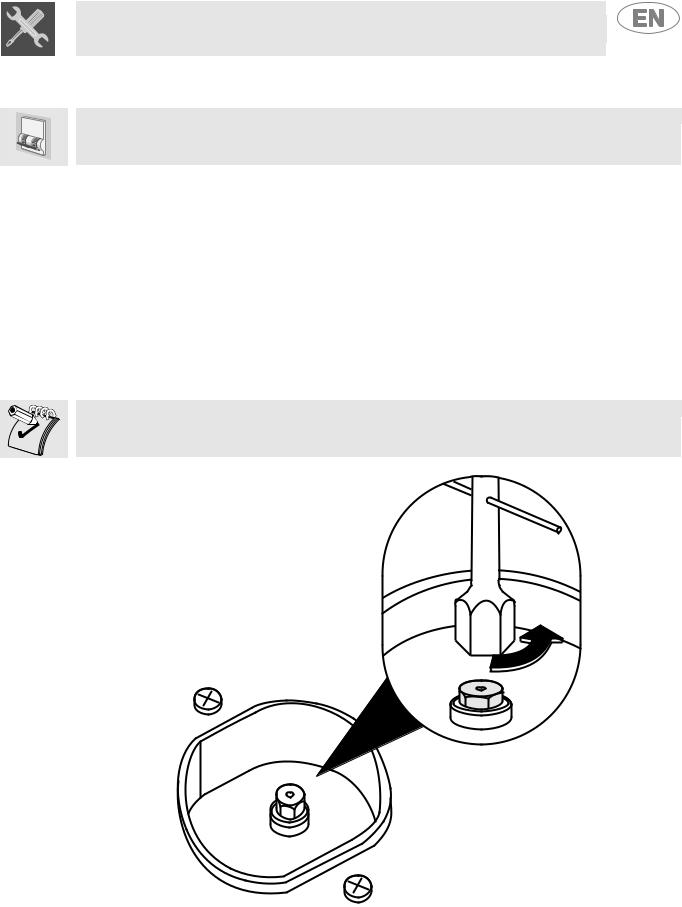
2.Unscrew the burner nozzles with a 7 mm socket wrench;
3.Replace the burner nozzles according to the gas to be used (see paragraph “3.2/3.3 Burner and nozzle characteristics table”).
4.Replace the burners in the correct position.
The nozzles for using city gas (G110 – 8 mbar) are available from authorised service centres.
39

Instructions for the installer
3.2Burner and nozzle characteristics table (60 cm model)
|
|
Rated |
|
|
|
|
|
|
|
|
|
|
|
|
Burner |
|
heating |
|
|
|
LIQUID GAS – G30/G31 30/37 mbar |
|
|
||||||
|
capacity |
|
|
|
|
|
||||||||
|
|
|
|
|
|
|
|
|
|
|
|
|
|
|
|
|
(kW) |
|
|
|
|
|
|
|
|
|
|
|
|
|
|
|
|
|
|
|
|
|
|
|
|
|
|
|
|
|
|
|
Nozzle |
|
By-pass |
|
Reduced |
|
Capacity |
|
Capacity |
||
|
|
|
|
diameter |
|
mm |
|
capacity |
|
|
||||
|
|
|
|
|
|
|
g/h G30 |
|
g/h G31 |
|||||
|
|
|
|
1/100 mm |
|
1/100 |
|
(W) |
|
|
||||
|
|
|
|
|
|
|
|
|
|
|||||
|
|
|
|
|
|
|
|
|
|
|
|
|
|
|
Auxiliary |
1.0 |
50 |
30 |
|
350 |
73 |
71 |
|||||||
|
|
|
|
|
|
|
|
|
|
|
|
|
|
|
Semi-rapid |
1.8 |
65 |
33 |
|
450 |
131 |
129 |
|||||||
|
|
|
|
|
|
|
|
|
|
|
|
|
|
|
Rapid (3) |
3.0 |
85 |
45 |
|
800 |
218 |
214 |
|||||||
|
|
|
|
|
|
|
|
|
|
|
|
|
|
|
Rapid (5) |
2.5 |
79 |
45 |
|
800 |
182 |
179 |
|||||||
|
|
|
|
|
|
|
|
|
|
|
|
|
|
|
Triple crown |
3.2 |
91 |
65 |
|
1500 |
233 |
229 |
|||||||
|
|
|
|
|
|
|
|
|
|
|
|
|
|
|
Oven |
3.2 |
87 |
50 |
|
900 |
233 |
229 |
|||||||
|
|
|
|
|
|
|
|
|
|
|
|
|
|
|
Grill |
2.9 |
87 |
// |
|
// |
|
211 |
207 |
||||||
|
|
|
|
|
|
|
|
|
|
|
|
|
|
|
|
|
Rated |
|
|
|
|
|
|
|
|
|
|
|
|
Burner |
|
heating |
|
|
|
CITY GAS – G110 8 mbar |
|
|
||||||
|
capacity |
|
|
|
|
|
||||||||
|
|
|
|
|
|
|
|
|
|
|
|
|
|
|
|
|
(kW) |
|
|
|
|
|
|
|
|
|
|
|
|
|
|
|
|
|
|
|
|
|
|
|
||||
|
|
|
|
|
Nozzle |
|
|
|
|
Reduced capacity |
||||
|
|
|
|
diameter 1/100 mm |
|
|
|
|
(W) |
|
|
|||
|
|
|
|
|
|
|
|
|
|
|
|
|
||
Auxiliary |
1.0 |
|
|
145 |
|
|
|
|
350 |
|
|
|||
|
|
|
|
|
|
|
|
|
|
|
|
|
||
Semi-rapid |
1.8 |
|
|
185 |
|
|
|
|
450 |
|
|
|||
|
|
|
|
|
|
|
|
|
|
|
|
|
||
Rapid (3) |
3.0 |
|
|
260 |
|
|
|
|
800 |
|
|
|||
|
|
|
|
|
|
|
|
|
|
|
|
|
||
Rapid (5) |
2.5 |
|
|
230 |
|
|
|
|
800 |
|
|
|||
|
|
|
|
|
|
|
|
|
|
|
|
|
||
Triple crown |
3.5 |
|
|
290 |
|
|
|
|
1200 |
|
|
|||
|
|
|
|
|
|
|
|
|
|
|
|
|
||
Oven |
3.2 |
|
|
270 |
|
|
|
|
900 |
|
|
|||
|
|
|
|
|
|
|
|
|
|
// |
|
|
||
Grill |
2.9 |
|
|
270 |
|
|
|
|
|
|
||||
|
|
|
|
|
|
|
|
|||||||
The values for city gas refer to appliances in category III 1a2H3+. |
|
|
|
|
|
|
|
|||||||
|
|
|
|
|
|
|
|
|
|
|
|
|
|
|
|
|
Rated |
|
|
|
|
|
|
|
|
|
|
|
|
Burner |
|
heating |
|
|
|
NATURAL GAS – G20 20 mbar |
|
|
||||||
|
capacity |
|
|
|
|
|
||||||||
|
|
|
|
|
|
|
|
|
|
|
|
|
|
|
|
|
(kW) |
|
|
|
|
|
|
|
|
|
|
|
|
|
|
|
|
|
|
|
|
|
|
|
||||
|
|
|
|
|
Nozzle |
|
|
|
|
Reduced capacity |
||||
|
|
|
|
diameter 1/100 mm |
|
|
|
|
(W) |
|
|
|||
|
|
|
|
|
|
|
|
|
|
|
|
|
||
Auxiliary |
1.0 |
|
|
72 |
|
|
|
|
350 |
|
|
|||
|
|
|
|
|
|
|
|
|
|
|
|
|
||
Semi-rapid |
1.8 |
|
|
97 |
|
|
|
|
450 |
|
|
|||
|
|
|
|
|
|
|
|
|
|
|
|
|
||
Rapid (3) |
3.0 |
|
|
115 |
|
|
|
|
800 |
|
|
|||
|
|
|
|
|
|
|
|
|
|
|
|
|
||
Rapid (5) |
2.5 |
|
|
108 |
|
|
|
|
800 |
|
|
|||
|
|
|
|
|
|
|
|
|
|
|
|
|
||
Triple crown |
3.5 |
|
|
133 |
|
|
|
|
1500 |
|
|
|||
|
|
|
|
|
|
|
|
|
|
|
|
|
||
Oven |
3.2 |
|
|
130 |
|
|
|
|
900 |
|
|
|||
|
|
|
|
|
|
|
|
|
|
// |
|
|
||
Grill |
2.9 |
|
|
130 |
|
|
|
|
|
|
||||
40

Instructions for the installer
3.3Burner and nozzle characteristics table (90 cm model)
|
|
|
Rated |
|
|
|
|
|
|
|
|
|
|
|
|
|
|
|
|
|
Burner |
|
heating |
|
|
|
|
LIQUID GAS – G30/G31 30/37 mbar |
|
|
|
||||||||
|
|
|
capacity |
|
|
|
|
|
|
|
|
|
|
|
|
|
|
|
|
|
|
|
(kW) |
|
|
|
|
|
|
|
|
|
|
|
|
|
|
|
|
|
|
|
|
|
|
|
|
|
|
|
|
|
|
|
|
|
|
|
|
|
|
|
|
|
Nozzle |
|
|
By-pass |
|
Reduced |
|
Capacity |
|
|
Capacity |
|
|
||
|
|
|
|
|
diameter |
|
|
mm |
|
capacity |
|
g/h G30 |
|
|
g/h G31 |
|
|
||
|
|
|
|
|
1/100 mm |
|
|
1/100 |
|
|
|
(W) |
|
|
|
|
|
|
|
|
|
|
|
|
|
|
|
|
|
|
|
|
|
|
|
|
|
|
|
|
Auxiliary |
|
1 |
|
50 |
|
|
30 |
|
350 |
|
73 |
|
|
71 |
|
|
||
|
|
|
|
|
|
|
|
|
|
|
|
|
|
|
|
|
|||
|
Semi-rapid |
|
1.8 |
|
65 |
|
|
33 |
|
450 |
|
131 |
|
|
129 |
|
|
||
|
|
|
|
|
|
|
|
|
|
|
|
|
|
|
|
|
|||
|
Rapid |
|
3 |
|
85 |
|
|
45 |
|
800 |
|
218 |
|
|
214 |
|
|
||
|
|
|
|
|
|
|
|
|
|
|
|
|
|
|
|
|
|||
|
Triple crown (4) |
|
3.2 |
|
91 |
|
|
65 |
|
1500 |
|
233 |
|
|
229 |
|
|
||
|
|
|
|
|
|
|
|
|
|
|
|
|
|
|
|
|
|||
|
Triple crown (8) |
|
3.5 |
|
94 |
|
|
65 |
|
1500 |
|
255 |
|
|
250 |
|
|
||
|
|
|
|
|
|
|
|
|
|
|
|
|
|
|
|
|
|||
|
Fish kettle |
|
1.9 |
|
68 |
|
|
45 |
|
800 |
|
138 |
|
|
136 |
|
|
||
|
|
|
|
|
|
|
|
|
|
|
|
|
|
|
|
|
|||
|
Oven |
|
3.2 |
|
87 |
|
|
50 |
|
900 |
|
233 |
|
|
229 |
|
|
||
|
|
|
|
|
|
|
|
|
|
|
|
|
|
|
|
|
|||
|
Maxi oven |
|
5.2 |
|
110 |
|
|
59 |
|
1300 |
|
378 |
|
|
372 |
|
|
||
|
|
|
|
|
|
|
|
|
|
|
|
|
|
|
|
|
|||
|
Grill |
|
2.9 |
|
87 |
|
|
// |
|
// |
|
211 |
|
|
207 |
|
|
||
|
|
|
|
|
|
|
|
|
|
|
|
|
|
|
|
|
|||
|
Maxi grill |
|
4.0 |
|
100 |
|
|
// |
|
// |
|
291 |
|
|
286 |
|
|
||
|
|
|
|
|
|
|
|
|
|
|
|
|
|
|
|
|
|
|
|
|
|
|
Rated |
|
|
|
|
|
|
|
|
|
|
|
|
|
|
|
|
Burner |
|
heating |
|
|
|
|
CITY GAS – G110 8 mbar |
|
|
|
|||||||||
|
|
|
capacity |
|
|
|
|
|
|
|
|
|
|
|
|
|
|
|
|
|
|
|
(kW) |
|
|
|
|
|
|
|
|
|
|
|
|
|
|
|
|
|
|
|
|
|
|
|
|
|
|
|
|
|
|
|
|||||
|
|
|
|
|
Nozzle diameter |
|
|
|
|
|
Reduced capacity |
|
|
|
|||||
|
|
|
|
|
|
1/100 mm |
|
|
|
|
|
(W) |
|
|
|
||||
|
|
|
|
|
|
|
|
|
|
|
|
|
|
|
|
||||
Auxiliary |
|
1 |
|
|
145 |
|
|
|
|
350 |
|
|
|
|
|
||||
|
|
|
|
|
|
|
|
|
|
|
|
|
|
|
|||||
Semi-rapid |
|
1.8 |
|
|
185 |
|
|
|
|
450 |
|
|
|
|
|
||||
|
|
|
|
|
|
|
|
|
|
|
|
|
|
|
|||||
Rapid |
|
3 |
|
|
260 |
|
|
|
|
800 |
|
|
|
|
|
||||
|
|
|
|
|
|
|
|
|
|
|
|
|
|
|
|||||
Triple crown |
|
3.5 |
|
|
290 |
|
|
|
|
1200 |
|
|
|
|
|
||||
|
|
|
|
|
|
|
|
|
|
|
|
|
|
|
|||||
Fish kettle |
|
1.9 |
|
|
190 |
|
|
|
|
800 |
|
|
|
|
|
||||
Gas G110 cannot |
|
be used in gas oven models. |
|
|
|
|
|
|
|
|
|
|
|
|
|
|
|||
The values for city gas refer to appliances in category III 1a2H3+. |
|
|
|
|
|
|
|
|
|
|
|
||||||||
|
|
|
|
|
|
|
|
|
|
|
|
|
|
|
|
|
|
|
|
|
|
|
|
|
|
|
|
|
|
|
|
|
|
|
|
|
|
|
|
|
|
|
Rated |
|
|
|
|
|
|
|
|
|
|
|
|
|
|
|
|
Burner |
|
heating |
|
|
|
|
NATURAL GAS – G20 20 mbar |
|
|
|
|||||||||
|
|
|
capacity |
|
|
|
|
|
|
|
|
|
|
|
|
|
|
|
|
|
|
|
(kW) |
|
|
|
|
|
|
|
|
|
|
|
|
|
|
|
|
|
|
|
|
|
|
|
|
|
|
|
|
|
|
|
|||||
|
|
|
|
|
Nozzle diameter |
|
|
|
|
|
Reduced capacity |
|
|
|
|||||
|
|
|
|
|
|
1/100 mm |
|
|
|
|
|
(W) |
|
|
|
||||
|
|
|
|
|
|
|
|
|
|
|
|
|
|
|
|||||
Auxiliary |
|
1 |
|
|
72 |
|
|
|
|
350 |
|
|
|
|
|
||||
|
|
|
|
|
|
|
|
|
|
|
|
|
|
|
|||||
Semi-rapid |
|
1.8 |
|
|
97 |
|
|
|
|
450 |
|
|
|
|
|
||||
|
|
|
|
|
|
|
|
|
|
|
|
|
|
|
|||||
Rapid |
|
3 |
|
|
115 |
|
|
|
|
800 |
|
|
|
|
|
||||
|
|
|
|
|
|
|
|
|
|
|
|
|
|
|
|||||
Triple crown (4) |
|
3.5 |
|
|
133 |
|
|
|
|
1500 |
|
|
|
|
|
||||
|
|
|
|
|
|
|
|
|
|
|
|
|
|
|
|||||
Triple crown (8) |
|
3.5 |
|
|
140 |
|
|
|
|
1500 |
|
|
|
|
|
||||
|
|
|
|
|
|
|
|
|
|
|
|
|
|
|
|||||
Fish kettle |
|
1.9 |
|
|
94 |
|
|
|
|
800 |
|
|
|
|
|
||||
|
|
|
|
|
|
|
|
|
|
|
|
|
|
|
|||||
Oven |
|
3.2 |
|
|
130 |
|
|
|
|
850 |
|
|
|
|
|
||||
|
|
|
|
|
|
|
|
|
|
|
|
|
|
|
|||||
Maxi oven |
|
5.2 |
|
|
164 |
|
|
|
|
1200 |
|
|
|
|
|
||||
|
|
|
|
|
|
|
|
|
|
|
|
|
|
|
|||||
Grill |
|
2.9 |
|
|
130 |
|
|
|
|
// |
|
|
|
|
|
||||
|
|
|
|
|
|
|
|
|
|
|
|
|
|
|
|||||
Maxi grill |
|
4.0 |
|
|
150 |
|
|
|
|
// |
|
|
|
|
|
||||
41
 Loading...