


USER AND MAINTENANCE MANUAL
Rev. 08 |
User and maintenance manual |
1 |
Smeg S.p.A. – Instruments Division
Via Leonardo da Vinci, 4 42016 Guastalla (RE) www.smeg-instruments.com
READ CAREFULLY
This manual constitutes an integral part of the refrigerating unit.
It must be kept intact and at hand for the entire life cycle of the machine. It is necessary to read the following manual carefully prior to using the device. Failure to read or thoroughly comprehend the instructions in this manual may cause the device to malfunction and present hazards to the user.
Machine installation, maintenance, and repair operations must be performed by authorized technical staff.
Repair operations performed by unauthorized staff, besides leading invalidating the product warranty, can be source of danger for the user.
In case of replacement, an original spare part must be used.
If the device was not used in accordance to the instructions presented in this manual, the product may no longer be covered by warranty and the safety of this device could be compromised.
The producer declines all liability for any use that differs from what indicated in the present manual.
The refrigerating unit has not to be used in presence of explosive gases or near sources with high electronic or magnetic fields.
The content of this manual is for information purposes only. The content and the equipment described here may be subject to change without notification. The colours used in photographs of the product (finishing panels), in diagrams and in screenshots are all purely guideline.
Rev. 08 |
User and maintenance manual |
2 |

SUMMARY |
|
||
Products applicable to this manual..................................................................................................... |
5 |
||
Table of capacity and dimensions ...................................................................................................... |
6 |
||
Table of technical specifications......................................................................................................... |
8 |
||
Standard and optional fitting............................................................................................................. |
10 |
||
1 |
STANDARDS AND GENERAL WARNINGS ........................................................................... |
12 |
|
1.1 |
|
Certification.......................................................................................................................... |
12 |
1.2 |
|
Initial reccomendations ........................................................................................................ |
12 |
1.3 |
|
Aim, content and intended user of this manual..................................................................... |
13 |
1.4 |
|
Product description .............................................................................................................. |
13 |
1.5 |
|
General safety regulations ................................................................................................... |
14 |
1.6 |
|
Customer responsibilities ..................................................................................................... |
14 |
1.7 |
|
Customer service requests .................................................................................................. |
14 |
1.8 |
|
Ordering of spare parts ........................................................................................................ |
14 |
1.9 |
|
Aim and intended use of device ........................................................................................... |
15 |
1.10 |
|
Unsuitable conditions for use ............................................................................................... |
15 |
1.11 |
|
Materials and refrigerants .................................................................................................... |
15 |
2 |
INSTALLATION....................................................................................................................... |
16 |
|
2.1 |
|
Trasportation and handling .................................................................................................. |
16 |
2.2 |
|
Positioning ........................................................................................................................... |
16 |
2.3 |
|
Wiring and electrical hook-up............................................................................................... |
17 |
2.4 |
|
Set-up operations ................................................................................................................ |
18 |
2.5 |
|
Re-installation ...................................................................................................................... |
18 |
2.6 |
|
Scrapping and disposal........................................................................................................ |
18 |
3 |
OPERATION ........................................................................................................................... |
20 |
|
3.1 |
|
Safety and accident prevention............................................................................................ |
20 |
3.2 |
|
Safety dataplates and guards .............................................................................................. |
20 |
3.3 |
|
Operating limits.................................................................................................................... |
20 |
3.4 |
|
Environmental storage conditions ........................................................................................ |
21 |
4 |
USER INSTRUCTIONS........................................................................................................... |
23 |
|
4.1 |
|
Appliance start-up................................................................................................................ |
23 |
4.2 |
|
Functions ............................................................................................................................. |
23 |
4.3 |
|
Control panel ....................................................................................................................... |
24 |
4.4 |
|
The menu tree ..................................................................................................................... |
25 |
4.5 |
|
Alarm codes......................................................................................................................... |
27 |
4.6 |
|
Download procedure............................................................................................................ |
28 |
4.7 |
|
Procedure to disable the data logger ................................................................................... |
29 |
4.8 |
|
Procedure to calibrate internal temperature probe S1 .......................................................... |
30 |
4.9 |
|
Update of firmware release .................................................................................................. |
30 |
4.10 |
|
GSM module........................................................................................................................ |
31 |
4.11 |
|
Dry contact for remote alarm................................................................................................ |
31 |
4.12 |
|
Back-up battery.................................................................................................................... |
32 |
4.13 |
|
Temperature chart recorder ................................................................................................. |
32 |
4.14 |
|
Shelf, drawer and installation ............................................................................................... |
35 |
4.15 |
|
Divider for drawer and its installation ................................................................................... |
36 |
5 |
ROUTINE MAINTENANCE ..................................................................................................... |
37 |
|
5.1 |
|
Cleaning of the refrigerator .................................................................................................. |
37 |
Rev. 08 |
User and maintenance manual |
3 |
|

5.2 |
Cleaning of the interior and exterior ..................................................................................... |
37 |
|
5.3 |
Cleaning of the condenser ................................................................................................... |
38 |
|
5.4 |
Precautions for prolonged disuse......................................................................................... |
39 |
|
6 |
SPECIAL MAINTENANCE AND REPAIRS ............................................................................. |
40 |
|
7 |
|
TROUBLESHOOTING ............................................................................................................ |
41 |
8 |
|
SYMBOLS USED .................................................................................................................... |
43 |
9 |
|
ANNEXES ............................................................................................................................... |
44 |
9.1 |
Technical Documentation .................................................................................................... |
44 |
|
9.1.1 |
Electric diagram ............................................................................................................... |
44 |
|
9.1.2 |
Safety test rerport............................................................................................................. |
44 |
|
10 |
|
AFTER-SALES SERVICE ....................................................................................................... |
45 |
Rev. 08 |
User and maintenance manual |
4 |
Products applicable to this manual
The present manual is exclusively valid and applicable to the following SMEG product series.
Laboratory refrigerators, Pharmacy refrigerators FV series
Adjustable temperature control range: lowest T = +2 °C, highest T = +15 °C Factory pre-set: +4 °C
Models: FV10G1A, FV15G1A, FV20G1A, FV25G1A, FV30G1A, FV45G1A, FV52G1A, FV70G1A, FV140G2A, FV10C1A, FV15C1A, FV20C1A, FV25C1A, FV30C1A, FV45C1A, FV52C1A, FV70C1A, FV140C2A, FV10G16A, FV15G16A, FV20G16A, FV25G16A, FV30G16A, FV45G16A,
FV52G16A, FV70G16A, FV140G26A, FV10C16A, FV15C16A, FV20C16A, FV25C16A, FV30C16A, FV45C16A, FV52C16A, FV70C16A, FV140C26A
Laboratory freezers C series
Adjustable temperature control range: lowest T = -25 °C, -32 °C, -42 °C, highest T = -10 °C Factory pre-set: -22 °C (C20), -30 °C (C30), -40 °C (C40)
Models: C20V10C1A, C30S16C1A, C30S22C1A, C30S25C1A, C30S32C1A, C40S60C1A, C25V70C1A, C25V140C2A, C20V10C16A, C30S16C16A, C30S22C16A, C30S25C16A, C30S32C16A, C40S60C16A, C25V70C16A, C25V140C26A
Combined refrigerators and freezers DT series
Adjustable temperature control range: lowest T = +2 *C / -25 °C, highest T = +12 °C / -10 °C Factory pre-set: +4 °C (refrigerator) / -25 °C (freezer)
Models: DT28CA, DT70CA, DT140CA, DT28GA, DT70GA, DT140GA, DT28C6A, DT70C6A, DT140C6A, DT28G6A, DT70G6A, DT140G6A
Dual positive refrigerators DTP series
Adjustable temperature control range: lowest T = +2 °C, highest T = +15 °C Factory pre-set: +4 °C
Models: DTP30CA, DTP70CA, DTP140CA, DTP30GA, DTP70GA, DTP140GA, DTP30C6A, DTP70C6A, DTP140C6A, DTP30G6A, DTP70G6A, DTP140G6A
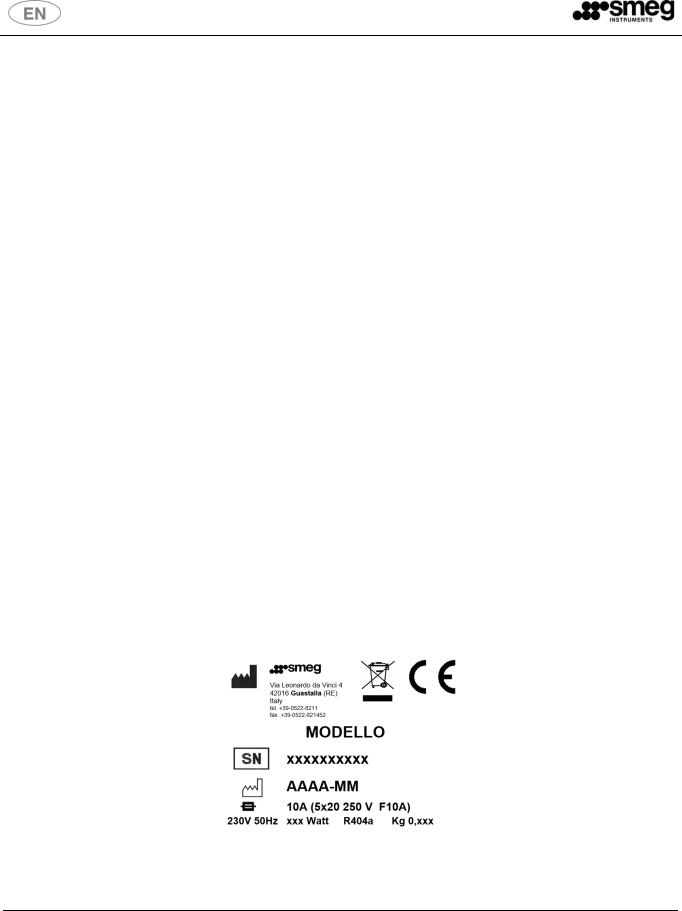
All relevant data referring to SMEG products can be found on the data label visible on the rear part of the cabinet. Here is an example of the label:
Rev. 08 |
User and maintenance manual |
5 |

Table of capacity and dimensions
|
|
|
|
|
|
Internal |
|
|
External dimension and |
|
|
Dimensions of |
|
|
|||
|
|
|
|
|
|
|
|
|
|
|
|
||||||
|
|
|
|
|
|
|
|
|
|
packaging and shipping |
|
|
|||||
|
|
|
|
|
|
dimensions |
|
|
unit net weigth |
|
|
|
|
||||
|
|
|
|
|
|
|
|
|
|
weight |
|
|
|
||||
|
|
|
|
|
|
|
|
|
|
|
|
|
|
|
|
||
|
|
|
|
|
|
|
|
|
|
|
|
|
|
|
|
||
|
MODEL |
|
Volume (L) |
|
|
LxDxH (mm) |
|
|
LxDxH (mm) |
Kg |
|
|
LxDxH (mm) |
|
Kg |
|
|
|
|
Laboratory refrigerators, Pharmacy refrigerators – FV series |
|
|
|
|
|
||||||||||
|
|
|
|
|
|
|
|
|
|
|
|
|
|
|
|
|
|
|
FV10C1A - FV10G1A |
|
100 |
|
|
480x465x460 |
|
600x600x860 |
73-76 |
|
|
680x680x1040 |
|
84-87 |
|
|
|
|
FV10C16A - FV10G16A |
|
|
|
|
|
|
|
|
|
|||||||
|
|
|
|
|
|
|
|
|
|
|
|
|
|
|
|
|
|
|
|
|
|
|
|
|
|
|
|
|
|
|
|
|
|
|
|
|
FV15C1A - FV15G1A |
|
150 |
|
|
480x465x720 |
|
600x600x1360 |
76-80 |
|
|
680x680x1590 |
|
87-91 |
|
|
|
|
FV15C16A - FV15G16A |
|
|
|
|
|
|
|
|
|
|||||||
|
|
|
|
|
|
|
|
|
|
|
|
|
|
|
|
|
|
|
|
|
|
|
|
|
|
|
|
|
|
|
|
|
|
|
|
|
FV20C1A - FV20G1A |
|
200 |
|
|
480x465x920 |
|
600x600x1560 |
85-91 |
|
|
680x680x1790 |
|
96-102 |
|
|
|
|
FV20C16A - FV20G16A |
|
|
|
|
|
|
|
|
|
|||||||
|
|
|
|
|
|
|
|
|
|
|
|
|
|
|
|
|
|
|
|
|
|
|
|
|
|
|
|
|
|
|
|
|
|
|
|
|
FV25C1A - FV25G1A |
|
250 |
|
|
480x465x1120 |
|
600x600x1760 |
93-102 |
|
|
680x680x2050 |
|
106-115 |
|
|
|
|
FV25C16A - FV25G16A |
|
|
|
|
|
|
|
|
|
|||||||
|
|
|
|
|
|
|
|
|
|
|
|
|
|
|
|
|
|
|
|
|
|
|
|
|
|
|
|
|
|
|
|
|
|
|
|
|
FV30C1A - FV30G1A |
|
300 |
|
|
480x465x1320 |
|
600x600x1960 |
104-113 |
|
|
680x680x2150 |
|
117-126 |
|
|
|
|
FV30C16A - FV30G16A |
|
|
|
|
|
|
|
|
|
|||||||
|
|
|
|
|
|
|
|
|
|
|
|
|
|
|
|
|
|
|
|
|
|
|
|
|
|
|
|
|
|
|
|
|
|
|
|
|
FV45C1A - FV45G1A |
|
450 |
|
|
580x670x1200 |
|
700x800x1840 |
121-130 |
|
|
750x850x2150 |
|
136-145 |
|
|
|
|
FV45C16A - FV45G16A |
|
|
|
|
|
|
|
|
|
|||||||
|
|
|
|
|
|
|
|
|
|
|
|
|
|
|
|
|
|
|
|
|
|
|
|
|
|
|
|
|
|
|
|
|
|
|
|
|
FV52C1A - FV52G1A |
|
520 |
|
|
580x670x1400 |
|
700x800x2040 |
129-138 |
|
|
750x850x2150 |
|
144-153 |
|
|
|
|
FV52C16A - FV52G16A |
|
|
|
|
|
|
|
|
|
|||||||
|
|
|
|
|
|
|
|
|
|
|
|
|
|
|
|
|
|
|
|
|
|
|
|
|
|
|
|
|
|
|
|
|
|
|
|
|
FV70C1A - FV70G1A |
|
700 |
|
|
580x670x1500 |
|
700x800x1990 |
137-142 |
|
|
750x850x2150 |
|
152-167 |
|
|
|
|
FV70C16A - FV70G16A |
|
|
|
|
|
|
|
|
|
|||||||
|
|
|
|
|
|
|
|
|
|
|
|
|
|
|
|
|
|
|
|
|
|
|
|
|
|
|
|
|
|
|
|
|
|
|
|
|
FV140C2A - FV140G2A |
|
1400 |
|
|
1280x670x1500 |
|
1400x800x1990 |
164-186 |
|
|
1500x850x2150 |
|
179-212 |
|
|
|
|
FV140C26A - FV140G26A |
|
|
|
|
|
|
|
|
||||||||
|
|
|
|
|
|
|
|
|
|
|
|
|
|
|
|
||
|
|
|
|
|
|
|
|
|
|
|
|
|
|||||
|
|
|
Combined refrigerators and freezers – DT series |
|
|
|
|
|
|||||||||
|
|
|
|
|
|
|
|
|
|
|
|
|
|
|
|
|
|
|
DT28CA – DT28GA |
|
180/100 |
|
|
TN 480x465x920 |
|
600x600x1970 |
121-125 |
|
|
680x680x2150 |
|
134-138 |
|
|
|
|
DT28C6A – DT28G6A |
|
|
|
BT 480x465x460 |
|
|
|
|
|
|
||||||
|
|
|
|
|
|
|
|
|
|
|
|
|
|
|
|||
|
|
|
|
|
|
|
|
|
|
|
|
|
|
|
|
|
|
|
DT70CA – DT70GA |
|
350/350 |
|
|
TN 580x670x685 |
|
700x800x2040 |
161-168 |
|
|
750x850x2150 |
|
174-181 |
|
|
|
|
DT70C6A – DT70G6A |
|
|
|
BT 580x670x685 |
|
|
|
|
|
|
||||||
|
|
|
|
|
|
|
|
|
|
|
|
|
|
|
|||
|
|
|
|
|
|
|
|
|
|
|
|
|
|
|
|
|
|
|
DT140CA – DT140GA |
|
700/700 |
|
|
TN 580x670x1500 |
|
1400x800x1990 |
195-217 |
|
|
1500x850x2150 |
|
221-243 |
|
|
|
|
DT140C6A – DT140G6A |
|
|
|
BT 580x670x1500 |
|
|
|
|
|
|
||||||
|
|
|
|
|
|
|
|
|
|
|
|
|
|
|
|||
|
|
|
|
|
|
|
|
|
|
|
|
|
|
|
|||
|
|
|
|
Laboratory freezers – C series |
|
|
|
|
|
|
|
|
|||||
|
|
|
|
|
|
|
|
|
|
|
|
|
|
|
|
|
|
|
C20V10C1A |
|
100 |
|
|
480X465X460 |
|
600x600x860 |
81 |
|
|
680X680X1040 |
|
92 |
|
|
|
|
C20V10C16A |
|
|
|
|
|
|
|
|
|
|||||||
|
|
|
|
|
|
|
|
|
|
|
|
|
|
|
|
|
|
|
|
|
|
|
|
|
|
|
|
|
|
|
|
|
|
|
|
|
C30S16C1A |
|
160 |
|
|
480x465x720 |
|
640x620x1400 |
85 |
|
|
680x680x1590 |
|
96 |
|
|
|
|
C30S16C16A |
|
|
|
|
|
|
|
|
|
|||||||
|
|
|
|
|
|
|
|
|
|
|
|
|
|
|
|
|
|
|
|
|
|
|
|
|
|
|
|
|
|
|
|
|
|
|
|
|
C30S22C1A |
|
220 |
|
|
480x465x920 |
|
640x620x1600 |
94 |
|
|
680x680x1790 |
|
105 |
|
|
|
|
C30S22C16A |
|
|
|
|
|
|
|
|
|
|||||||
|
|
|
|
|
|
|
|
|
|
|
|
|
|
|
|
|
|
|
|
|
|
|
|
|
|
|
|
|
|
|
|
|
|
|
|
|
C30S25C1A |
|
250 |
|
|
480x465x1120 |
|
640x620x1800 |
103 |
|
|
680x680x2050 |
|
116 |
|
|
|
|
C30S25C16A |
|
|
|
|
|
|
|
|
|
|||||||
|
|
|
|
|
|
|
|
|
|
|
|
|
|
|
|
|
|
|
|
|
|
|
|
|
|
|
|
|
|
|
|
|
|
|
|
|
C30S32C1A |
|
320 |
|
|
480x465x1320 |
|
640x620x2000 |
115 |
|
|
680x680x2150 |
|
128 |
|
|
|
|
C30S32C16A |
|
|
|
|
|
|
|
|
|
|||||||
|
|
|
|
|
|
|
|
|
|
|
|
|
|
|
|
|
|
|
|
|
|
|
|
|
|
|
|
|
|
|
|
|
|
|
|
|
C40S60C1A |
|
600 |
|
|
580x670x1400 |
|
780x840x1930 |
173 |
|
|
910x850x2100 |
|
186 |
|
|
|
|
C30S32C16A |
|
|
|
|
|
|
|
|
|
|||||||
|
|
|
|
|
|
|
|
|
|
|
|
|
|
|
|
|
|
|
|
|
|
|
|
|
|
|
|
|
|
|
|
|
|
|
|
|
C25V70C1A |
|
700 |
|
|
580x670x1500 |
|
700x800x1990 |
144 |
|
|
750x850x2150 |
|
157 |
|
|
|
|
C25V70C16A |
|
|
|
|
|
|
|
|
|
|||||||
|
|
|
|
|
|
|
|
|
|
|
|
|
|
|
|
|
|
|
|
|
|
|
|
|
|
|
|
|
|
|
|
|
|
|
|
|
|
|
|
|
|
|
|
|
|
|
|
|
|
|
|
|
|
|
Rev. 08 |
|
|
User and maintenance manual |
|
|
|
|
|
6 |
|
|
|||||

|
|
|
|
|
|
Internal |
|
|
External dimension and |
|
|
Dimensions of |
|
|||
|
|
|
|
|
|
|
|
|
|
|
||||||
|
|
|
|
|
|
|
|
|
|
packaging and shipping |
|
|||||
|
|
|
|
|
|
dimensions |
|
|
unit net weigth |
|
|
|
||||
|
|
|
|
|
|
|
|
|
|
weight |
|
|
||||
|
|
|
|
|
|
|
|
|
|
|
|
|
|
|
||
|
|
|
|
|
|
|
|
|
|
|
|
|
|
|
|
|
|
MODEL |
|
Volume (L) |
|
|
LxDxH (mm) |
|
|
LxDxH (mm) |
Kg |
|
|
LxDxH (mm) |
|
Kg |
|
|
|
Laboratory refrigerators, Pharmacy refrigerators – FV series |
|
|
|
|
||||||||||
|
|
|
|
|
|
|
|
|
|
|
|
|
|
|
|
|
|
C25V140C2A |
|
1400 |
|
|
1280x670x1500 |
|
1400x800x1990 |
171 |
|
|
1500x850x2150 |
|
197 |
|
|
|
C25V140C26A |
|
|
|
|
|
|
|
|
|||||||
|
|
|
|
|
|
|
|
|
|
|
|
|
|
|
|
|
|
|
|
|
|
|
|
|
|
|
|
|
|
||||
|
|
|
Dual positive refrigerators – DTP series |
|
|
|
|
|
|
|
||||||
|
|
|
|
|
|
|
|
|
|
|
|
|
|
|
|
|
|
DTP30CA - DTP30GA |
|
150/150 |
|
|
TN1 480x465x720 |
|
600x600x1960 |
125-131 |
|
|
680x680x2150 |
|
138-144 |
|
|
|
DTP30C6A - DTP30G6A |
|
|
|
TN2 480x465x720 |
|
|
|
|
|
||||||
|
|
|
|
|
|
|
|
|
|
|
|
|
|
|||
|
|
|
|
|
|
|
|
|
|
|
|
|
|
|
|
|
|
DTP70CA – DTP70GA |
|
350/350 |
|
|
TN1 580x670x685 |
|
700x800x2040 |
161-168 |
|
|
750x850x2150 |
|
174-181 |
|
|
|
DTP70C6A – DTP70G6A |
|
|
|
TN2 580x670x685 |
|
|
|
|
|
||||||
|
|
|
|
|
|
|
|
|
|
|
|
|
|
|||
|
|
|
|
|
|
|
|
|
|
|
|
|
|
|
|
|
|
DTP140CA – DTP140GA |
|
700/700 |
|
|
TN1 580x670x1500 |
|
1400x800x1990 |
195-217 |
|
|
1500x850x2150 |
|
221-243 |
|
|
|
DTP140C6A – DTP140G6A |
|
|
TN2 580x670x1500 |
|
|
|
|
|
|||||||
|
|
|
|
|
|
|
|
|
|
|
|
|
||||
|
|
|
|
|
|
|
|
|
|
|
|
|
|
|
|
|
Legend:
TN = Reefrigerator compartment
BT = Freezer compartment
Rev. 08 |
User and maintenance manual |
7 |

Table of technical specifications
|
MODEL |
|
|
Volume (L) |
|
|
Voltage (V) / Frequency (Hz) |
|
|
Absorption (W) |
|
|
Gas |
|
|
Q.ty (Kg) |
|
|
|
|
|
|
|
|
|
|
|
|
|
||||||
|
|
|
|
|
|
|
|
|
|
|
|
|
|
|
|
|
|
Laboratory refrigerators, Pharmacy refrigerators – FV series
|
FV10C1A - FV10G1A |
100 |
|
230 / 50 |
|
245 |
R404a |
0,130 |
|
|
FV10C16A - FV10G16A |
|
230 / 60 |
|
245 |
|
|||
|
|
|
|
|
|
|
|||
|
|
|
|
|
|
|
|
|
|
|
FV15C1A - FV15G1A |
150 |
|
230 / 50 |
|
245 |
R404a |
0,150 |
|
|
FV15C16A - FV15G16A |
|
230 / 60 |
|
245 |
|
|||
|
|
|
|
|
|
|
|||
|
|
|
|
|
|
|
|
|
|
|
FV20C1A - FV20G1A |
200 |
|
230 / 50 |
|
245 |
R404a |
0,180 |
|
|
FV20C16A - FV20G16A |
|
230 / 60 |
|
245 |
|
|||
|
|
|
|
|
|
|
|||
|
|
|
|
|
|
|
|
|
|
|
FV25C1A - FV25G1A |
250 |
|
230 / 50 |
|
360 |
R404a |
0,200 |
|
|
FV25C16A - FV25G16A |
|
230 / 60 |
|
360 |
|
|||
|
|
|
|
|
|
|
|||
|
|
|
|
|
|
|
|
|
|
|
FV30C1A - FV30G1A |
300 |
|
230 / 50 |
|
360 |
R404a |
0,250 |
|
|
FV30C16A - FV30G16A |
|
230 / 60 |
|
360 |
|
|||
|
|
|
|
|
|
|
|||
|
|
|
|
|
|
|
|
|
|
|
FV45C1A - FV45G1A |
450 |
|
230 / 50 |
|
336 |
R404a |
0,250 |
|
|
FV45C16A - FV45G16A |
|
230 / 60 |
|
370 |
|
|||
|
|
|
|
|
|
|
|||
|
|
|
|
|
|
|
|
|
|
|
FV52C1A - FV52G1A |
520 |
|
230 / 50 |
|
336 |
R404a |
0,250 |
|
|
FV52C16A - FV52G16A |
|
230 / 60 |
|
370 |
|
|||
|
|
|
|
|
|
|
|||
|
|
|
|
|
|
|
|
|
|
|
FV70C1A - FV70G1A |
700 |
|
230 / 50 |
|
260 |
R404a |
0,250 |
|
|
FV70C16A - FV70G16A |
|
230 / 60 |
|
320 |
|
|||
|
|
|
|
|
|
|
|||
|
|
|
|
|
|
|
|
|
|
|
FV140C2A - FV140G2A |
1400 |
|
230 / 50 |
|
490 |
R404a |
0,340 |
|
|
FV140C26A - FV140G26A |
|
230 / 60 |
|
647 |
|
|||
|
|
|
|
|
|
|
|||
|
|
|
|
|
|
|
|
||
|
|
Combined refrigerators and freezers – DT series |
|
|
|
||||
|
|
|
|
|
|
|
|
|
|
|
DT28CA – DT28GA |
180/100 |
|
230 / 50 |
|
427 |
R404a |
0,150+0,130 |
|
|
DT28C6A – DT28G6A |
|
230 / 60 |
|
708 |
|
|||
|
|
|
|
|
|
|
|||
|
|
|
|
|
|
|
|
|
|
|
DT70CA – DT70GA |
350/350 |
|
230 / 50 |
|
350+480 |
R404a |
0,200+0,200 |
|
|
DT70C6A – DT70G6A |
|
230 / 60 |
|
295+450 |
|
|||
|
|
|
|
|
|
|
|||
|
|
|
|
|
|
|
|
|
|
|
DT140CA – DT140GA |
700/700 |
|
230 / 50 |
|
1100 |
R404a |
0,340+0,340 |
|
|
DT140C6A – DT140G6A |
|
230 / 60 |
|
1100 |
|
|||
|
|
|
|
|
|
|
|||
|
|
|
|
|
|
|
|
|
|
|
|
|
Laboratory freezers – C series |
|
|
|
|
||
|
|
|
|
|
|
|
|
|
|
|
C20V10C1A |
100 |
|
230 / 50 |
|
345 |
R404a |
0,130 |
|
|
C20V10C16A |
|
230 / 60 |
|
345 |
|
|||
|
|
|
|
|
|
|
|||
|
|
|
|
|
|
|
|
|
|
|
C30S16C1A |
160 |
|
230 / 50 |
|
450 |
R404a |
0,200 |
|
|
C30S16C16A |
|
230 / 60 |
|
450 |
|
|||
|
|
|
|
|
|
|
|||
|
|
|
|
|
|
|
|
|
|
|
C30S22C1A |
220 |
|
230 / 50 |
|
450 |
R404a |
0,200 |
|
|
C30S22C16A |
|
230 / 60 |
|
450 |
|
|||
|
|
|
|
|
|
|
|||
|
|
|
|
|
|
|
|
|
|
|
C30S25C1A |
250 |
|
230 / 50 |
|
450 |
R404a |
0,230 |
|
|
C30S25C16A |
|
230 / 60 |
|
450 |
|
|||
|
|
|
|
|
|
|
|||
|
|
|
|
|
|
|
|
|
|
|
C30S32C1A |
320 |
|
230 / 50 |
|
450 |
R404a |
0,230 |
|
|
C30S32C16A |
|
230 / 60 |
|
450 |
|
|||
|
|
|
|
|
|
|
|||
|
|
|
|
|
|
|
|
|
|
|
C40S60C1A |
600 |
|
230 / 50 |
|
580 |
R404a |
0,550 |
|
|
C40S60C16A |
|
230 / 60 |
|
580 |
|
|||
|
|
|
|
|
|
|
|||
|
|
|
|
|
|
|
|
|
|
|
C25V70C1A |
700 |
|
230 / 50 |
|
530 |
R404a |
0,290 |
|
|
C25V70C16A |
|
230 / 60 |
|
588 |
|
|||
|
|
|
|
|
|
|
|||
|
|
|
|
|
|
|
|
|
|
|
C25V140C2A |
1400 |
|
230 / 50 |
|
614 |
R404a |
0,500 |
|
|
C25V140C26A |
|
230 / 60 |
|
970 |
|
|||
|
|
|
|
|
|
|
|||
|
|
|
|
|
|
|
|
|
|
Rev. 08 |
User and maintenance manual |
8 |

|
MODEL |
|
|
Volume (L) |
|
|
Voltage (V) / Frequency (Hz) |
|
|
Absorption (W) |
|
|
Gas |
|
|
Q.ty (Kg) |
|
|
|
|
|
|
|
|
|
|
|
|
|
||||||
|
|
|
|
|
|
|
|
|
|
|
|
|
|
|
|
|
|
Dual positive refrigerators – DTP series
DTP30CA - DTP30GA |
150/150 |
230 / 50 |
245+245 |
R404a |
0,150+0,150 |
|
DTP30C6A - DTP30G6A |
230 / 60 |
245+245 |
||||
|
|
|
||||
|
|
|
|
|
|
|
DTP70CA – DTP70GA |
350/350 |
230 / 50 |
350+350 |
R404a |
0,200+0,200 |
|
DTP70C6A – DTP70G6A |
230 / 60 |
295+295 |
||||
|
|
|
||||
|
|
|
|
|
|
|
DTP140CA – DTP140GA |
700/700 |
230 / 50 |
260+260 |
R404a |
0,340+0,340 |
|
DTP140C6A – DTP140G6A |
230 / 60 |
320+320 |
||||
|
|
|
||||
|
|
|
|
|
|
Legend:
TN = Reefrigerator compartment
BT = Freezer compartment
Rev. 08 |
User and maintenance manual |
9 |

Standard and optional fitting
|
MODEL |
|
|
Shelves |
|
|
Drawers |
|
|
Standard fitting |
|
|
Optional accessories |
|
|
|
|
|
|
|
|
|
|
|
|||||
|
|
|
|
|
|
|
|
|
|
|
|
|
|
|
Laboratory refrigerators, Pharmacy refrigerators – FV series
|
FV10C1A - FV10G1A |
2 |
|
2* |
|
|
|
|
|
FV10C16A - FV10G16A |
|
|
|
|
|||
|
|
|
|
|
|
|
|
|
|
|
|
|
|
|
|
|
|
|
FV15C1A - FV15G1A |
2 |
|
3* |
|
|
|
|
|
FV15C16A - FV15G16A |
|
|
|
|
|||
|
|
|
|
|
|
|
|
|
|
|
|
|
|
|
|
|
|
|
FV20C1A - FV20G1A |
3 |
|
4* |
|
|
|
|
|
FV20C16A - FV20G16A |
|
|
|
|
|||
|
|
|
|
|
|
|
|
|
|
|
|
|
|
|
Shelves |
|
|
|
FV25C1A - FV25G1A |
|
|
|
|
Drawers |
|
|
|
4 |
|
5* |
One way wheels |
|
|||
|
FV25C16A - FV25G16A |
|
Kit of dividers for drawers |
|
||||
|
|
|
|
|
Schuko type plug |
|
||
|
|
|
|
|
|
Wheels with frontal brakes |
|
|
|
|
|
|
|
|
|
||
|
FV30C1A - FV30G1A |
|
|
|
|
Control panel with alarm |
|
|
|
5 |
|
6* |
Chart recorder |
|
|||
|
FV30C16A - FV30G16A |
|
system |
|
||||
|
|
|
|
|
Battery back up |
|
||
|
|
|
|
|
|
Remote alarm |
|
|
|
FV45C1A - FV45G1A |
|
|
|
|
SMS Alarms |
|
|
|
3 |
|
5* |
USB port |
|
|||
|
FV45C16A - FV45G16A |
|
LAN port |
|
||||
|
|
|
|
|
Data logger |
|
||
|
|
|
|
|
|
|
|
|
|
FV52C1A - FV52G1A |
4 |
|
6* |
|
|
|
|
|
FV52C16A - FV52G16A |
|
|
|
|
|||
|
|
|
|
|
|
|
|
|
|
|
|
|
|
|
|
|
|
|
FV70C1A - FV70G1A |
4 |
|
7* |
|
|
|
|
|
FV70C16A - FV70G16A |
|
|
|
|
|||
|
|
|
|
|
|
|
|
|
|
|
|
|
|
|
|
|
|
|
FV140C2A - FV140G2A |
4+4 |
|
14* |
|
|
|
|
|
FV140C26A - FV140G26A |
|
|
|
|
|||
|
|
|
|
|
|
|
|
|
|
|
|
|
|
|
|
|
|
|
|
|
Combined refrigerators and freezers – DT series |
|
|
|||
|
|
|
|
|
|
|
|
|
|
DT28CA – DT28GA |
|
3 (TN) |
|
2 (BT) |
Shelves/drawers (see previous |
Shelves/drawers (see previous |
|
|
DT28C6A – DT28G6A |
|
|
box) |
|
|||
|
|
|
|
|
box) |
|
||
|
|
|
|
|
|
One way wheels |
|
|
|
|
|
|
|
|
Kit of dividers for drawers |
|
|
|
|
|
|
|
|
|
||
|
|
|
|
|
|
Schuko type plug |
|
|
|
DT70CA – DT70GA |
|
|
|
|
Wheels with frontal brakes |
|
|
|
|
2 (TN) |
|
3 (BT) |
Control panel with alarm |
|
||
|
DT70C6A – DT70G6A |
|
|
Chart recorder |
|
|||
|
|
|
|
|
system |
|
||
|
|
|
|
|
|
Battery back up |
|
|
|
|
|
|
|
|
Remote alarm |
|
|
|
|
|
|
|
|
SMS alarms |
|
|
|
DT140CA – DT140GA |
|
|
|
|
USB port |
|
|
|
|
4+4 (TN+BT) |
4*+4* (TN+BT) |
LAN port |
|
|||
|
DT140C6A – DT140G6A |
|
Data logger |
|
||||
|
|
|
|
|
|
|
||
|
|
|
|
|
|
|
|
|
|
|
|
|
Laboratory freezers – C series |
|
|
||
|
|
|
|
|
|
|
|
|
|
C20V10C1A |
|
|
|
2 |
|
|
|
|
C20V10C16A |
|
|
|
|
|
|
|
|
|
|
|
|
|
|
|
|
|
|
|
|
|
|
|
|
|
|
C30S16C1A |
|
|
|
3 |
|
|
|
|
|
|
|
|
|
|
||
|
C30S16C16A |
|
|
|
|
|
|
|
|
|
|
|
|
|
|
|
|
|
C30S22C1A |
|
|
|
4 |
Shelves/drawers (see previous |
|
|
|
|
|
|
|
|
|||
|
C30S22C16A |
|
|
|
Shelves/drawers (see previous |
|
||
|
|
|
|
|
box) |
|
||
|
C30S25C1A |
|
|
|
|
One way wheels |
box) |
|
|
|
|
|
|
|
|||
|
|
|
|
5 |
Kit of dividers for drawers |
|
||
|
C30S25C16A |
|
|
|
Schuko type plug |
|
||
|
|
|
|
|
Wheels with frontal brakes |
|
||
|
|
|
|
|
|
Control panel with alarm |
|
|
|
C30S32C1A |
|
|
|
|
Chart recorder |
|
|
|
|
|
|
6 |
system |
|
||
|
|
|
|
Battery back up |
|
|||
|
C30S32C16A |
|
|
|
Remote alarm |
|
||
|
|
|
|
|
SMS alarms |
|
||
|
|
|
|
|
|
USB port |
|
|
|
C40S60C1A |
|
|
|
|
LAN port |
|
|
|
|
|
|
6 |
Data logger |
|
||
|
C40S60C16A |
|
|
|
|
|
||
|
|
|
|
|
|
|
|
|
|
C25V70C1A |
4 |
|
7* |
|
|
|
|
|
C25V70C16A |
|
|
|
|
|||
|
|
|
|
|
|
|
|
|
|
|
|
|
|
|
|
|
|
|
C25V140C2A |
8 |
|
7*+7* |
|
|
|
|
|
C25V140C26A |
|
|
|
|
|||
|
|
|
|
|
|
|
|
|
|
|
|
|
|
|
|
|
|
|
|
|
|
|
|
|
|
|
|
Rev. 08 |
|
|
User and maintenance manual |
10 |
|
||
|
MODEL |
|
|
Shelves |
|
|
Drawers |
|
|
Standard fitting |
|
|
Optional accessories |
|
|
|
|
|
|
|
|
|
|
|
|||||
|
|
|
|
|
|
|
|
|
|
|
|
|
|
|
Dual positive refrigerators – DTP series
DTP30CA - DTP30GA |
2+2 |
3*+3* |
Shelves |
Drawers |
|
DTP30C6A - DTP30G6A |
One way wheels |
||||
|
|
Kit of dividers for drawers |
|||
|
|
|
Schuko type plug |
||
DTP70CA – DTP70GA |
|
|
Wheels with frontal brakes |
||
2+2 |
3*+3* |
Control panel with alarm |
|||
DTP70C6A – DTP70G6A |
Chart recorder |
||||
|
|
system |
|||
|
|
|
Battery back up |
||
|
|
|
Remote alarm |
||
DTP140CA – DTP140GA |
|
|
SMS Alarms |
||
4+4 |
7*+7* |
USB port |
|||
DTP140C6A – DTP140G6A |
LAN port |
||||
|
|
Data logger |
|||
|
|
|
|
||
|
|
|
|
|
* Alternative configuration as optional
Rev. 08 |
User and maintenance manual |
11 |

1 STANDARDS AND GENERAL WARNINGS
1.1Certification
All appliances are produced in accordance with European Community Regulations applicable at the time of its appearance on the market. All appliances are manufactured in accordance with European Directive 2014/35/UE, 2014/30/UE and following integrations and according to safety requirements for electrical equipment for laboratory use (IEC 61010-1).
1.2 Initial reccomendations
READ THE PRESENT INSTRUCTION MANUAL CAREFULLY
This manual constitutes an integral part of the machine.
It must be kept intact and at hand for the entire life cycle of the machine.
It is necessary to read the following manual carefully prior to using the device.
Failure to read or thoroughly comprehend the instructions in this manual may cause the device to malfunction and present hazards to the user.
Machine installation, maintenance, and repair operations must be performed by authorized technical staff.
Repair operations performed by unauthorized staff, besides leading invalidating the product warranty, can be source of danger for the user.
In case of replacement, an original spare part must be used.
If the device was not used in accordance to the instructions presented in this manual, the product may no longer be covered by warranty and the safety of this device could be compromised.
The producer declines all liability for any use that differs from what indicated in the present manual.
The product warranty does not cover faulty parts due to negligence, inappropriate use, or failure to comply with the instructions of the device operations; incorrect installation or maintenance; repair and maintenance operations performed by unauthorized staff or with non-original spare parts; transportation damages; and any circumstance that cannot be ascribed to the device manufacturing defects.
Moreover, the warranty does not cover operations related to installation and connection of alimentation and drain systems as well as maintenance operations provided in the instruction booklet.
The installation of any accessory on the machine must be performed by authorized technical staff.
To request further information about accessories: contact your trusted seller and/or the authorized technical assistance, using the contact details provided in this manual.
The content of this manual is for information purposes only. The content and the equipment described here may be subject to change without notification.
Rev. 08 |
User and maintenance manual |
12 |

1.3 Aim, content and intended user of this manual
This manual has been prepared with the objective to supply all instructions required for the correct use of the appliance and to keep it in optimal condition. It also contains important user safety information. The following professional roles are explained in order to define the responsibilities of each involved parties.
Installer: a qualified technician, authorised by the manufacturer, who installs the appliance in accordance with the instructions herein contained.
User: the person who, after having read this manual carefully, uses the appliance in accordance with the intended specification of use described in this manual.
User’s responsibilities:
ensure that the product is kept at suitable temperatures without exceeding +38° of ambient temperature;
be aware of the regulations governing the conservation of products to refrigerate and to observe any whatsoever hygiene indications that may be applicable.
The user is obliged to read carefully the manual and refer to its information at all times. Particular attention must be paid to the contents of heading 1.4 General safety warnings.
Routine maintenance technician: qualified operator able to perform routine maintenance of the appliance by following the instructions in this manual (can be the customer too e).
Service engineer: qualified technician, authorised by the manufacturer to perform extraordinary maintenance of the appliance.
Installer and service engineer must always be authorized by the manufacturer.
The manufacturer declines any whatsoever responsibility in case of improper use of the appliance deviating from the reasonably construed intended use, and for all operations carried out that are not in compliance with the instructions reported in the manual.
This manual must be stored in an accessible and known place for all operators (installer, user, routine maintenance technician, service engineer).
1.4 Product description
The appliance comprises a single body with panelling in various materials and insulation in expanded polyurethane foam density. The appliance instruments are located on the front panel where the electrical wiring is housed. The motor unit and the condenser unit can be housed either on the top or on the bottom closed by a frontal panel and a rear grid. The interior parts are fitted with suitable supports for shelves, drawers and/or other accessories. The doors are fitted with an automatic return device and magnetic seal elements. During the design and construction stage all measures have been adopted to implement total safety including radius interior corners, funnel-shaped base panel to convey condensate to exterior, no rough surfaces, fixed guards protecting moving or potentially dangerous parts.
Rev. 08 |
User and maintenance manual |
13 |
1.5 General safety regulations
Read this manual carefully and follow the prescriptions contained herein.
The user assumes full responsibility in case of operations carried out without observing the instructions in the manual. None of SMEG products are designed to work in presence of flammable gases or solvent that may easily burn, hence keep off the unit of any of these situations.
Primary general safety regulations:
do not touch the unit with wet hands and/or feet
do not use the appliance with bare feet
do not insert screwdrivers or other pointed objects between guards or moving parts of the appliance
do not pull the power cord to disconnect the appliance from the electrical mains
make sure that the appliance is not used by unsuitably qualified persons
before performing any cleaning or maintenance on the appliance disconnect it from the electrical mains by switching off the main switch and extracting the plug
in case of faults or malfunctions, switch off the appliance and do not attempt to repair it by yourself. All service and repair operations must be performed exclusively by a suitable authorized engineer.
This symbol on the equipment indicates a situation of danger. Pay attention and read carefully what it refers to.
1.6 Customer responsibilities
The customer is required to:
execute the electrical connection of the appliance
prepare the place of installation
provide consumable materials for cleaning
perform routine maintenance
In the case of power failures or malfunctions do not open the doors in order to maintain as much as possible the internal temperature. If the problem persists for more than few hours, move the contents to a more suitable place.
1.7 Customer service requests
For all technical problems and any requests for technical service, refer exclusively to your local dealer, pointing out model and serial number.
1.8 Ordering of spare parts
Orders of spare parts should be made by consulting the part reference code and the serial number of your appliance. Consult your dealer.
Rev. 08 |
User and maintenance manual |
14 |
 Loading...