


D51GV
Table of contents
 Loading...
Smeg D51GV, D61GV, CX81GVET, D81GV, SX81GVE User Manual
...
Contents
E
_
1 INSTRUCTIONS FOR SAFETY AND US
___________________________________31
2 RECYCLING INSTRUCTIONS - OUR ENVIRONMENT POLICY ___________________33
3 INSTALLING THE APPLIANCE_____________________________________________34
4 ADAPTATION TO DIFFERENT TYPES OF GAS _______________________________38
5 FINAL OPERATIONS ____________________________________________________44
6 DESCRIPTION OF THE CONTROLS ON THE FRONT PANEL____________________46
7 USING THE COOKING HOB_______________________________________________48
8 USING THE OVEN ______________________________________________________50
9 AVAILABLE ACCESSORIES_______________________________________________53
10 CLEANING AND MAINTENANCE ___________________________________________54
11 EXTRAORDINARY MAINTENANCE _________________________________________56
INSTRUCTIONS FOR THE INSTALLER: these are intended for the qualified technician who must
carry out an adequate inspection of the gas system, install the appliance, set it functioning and carry
out an inspection test.
INSTRUCTIONS FOR THE USER: these contain user advice, description of the commands and the
correct procedures for cleaning and maintenance of the appliance.
30
Presentation
1 INSTRUCTIONS FOR SAFETY AND USE
THIS MANUAL IS AN INTEGRAL PART OF THE APPLIANCE. THEREFORE IT MUST BE KEPT IN
ITS ENTIRETY AND IN AN ACCESSIBLE PLACE FOR THE WHOLE WORKING LIFE OF THE
COOKER. WE URGE YOU TO READ THIS MANUAL AND ALL THE INFORMATION IT CONTAINS
CAREFULLY BEFORE USING THE COOKER. MAKE ALSO SURE TO KEEP THE SERIES OF
SUPPLIED NOZZLES. INSTALLATION MUST BE CARRIED OUT BY QUALIFIED PERSONNEL IN
ACCORDANCE WITH THE REGULATIONS IN FORCE. THIS APPLIANCE IS INTENDED FOR
DOMESTIC USE AND CONFORMS TO THE EEC DIRECTIVES CURRENTLY IN FORCE. THE
APPLIANCE HAS BEEN BUILT TO CARRY OUT THE FOLLOWING FUNCTIONS: COOKING AND
HEATING-UP OF FOOD; ALL OTHER USES ARE CONSIDERED IMPROPER.
THE MANUFACTURER DECLINES ALL RESPONSIBILITY FOR IMPROPER USE.
NEVER LEAVE DISCARDED PACKAGING UNATTENDED IN THE HOME.
SEPARATE WASTE PACKAGING MATERIALS BY TYPE AND CONSIGN THEM TO THE
NEAREST SELECTIVE DISPOSAL CENTRE.
IT IS OBLIGATORY FOR ALL ELECTRICAL SYSTEMS TO BE GROUNDED IN COMPLIANCE
WITH ELECTRICAL SYSTEM SAFETY REGULATIONS.
THE PLUG TO BE CONNECTED TO THE POWER SUPPLY CABLE AND ITS SOCKET MUST BE
OF THE SAME TYPE AND CONFORM TO THE REGULATIONS IN FORCE.
THE SOCKET MUST BE ACCESSIBLE AFTER THE APPLIANCE HAS BEEN BUILT-IN.
NEVER UNPLUG BY PULLING ON THE CABLE.
IMMEDIATELY AFTER INSTALLATION, CARRY OUT A QUICK TEST ON THE APPLIANCE
FOLLOWING THE INSTRUCTIONS PROVIDED LATER IN THIS MANUAL. SHOULD THE
APPLIANCE NOT FUNCTION, DISCONNECT IT FROM THE SUPPLY AND CALL THE NEAREST
TECHNICAL ASSISTANCE CENTRE.
NEVER ATTEMPT TO REPAIR THE APPLIANCE.
ALWAYS CHECK THAT THE CONTROL KNOBS ARE IN THE
FINISH USING THE APPLIANCE.
(OFF) POSITION WHEN YOU
NEVER PLACE FLAMMABLE OBJECTS IN THE OVEN: IF IT SHOULD ACCIDENTALLY BE
SWITCHED ON, THIS MIGHT CAUSE A FIRE.
THE IDENTIFICATION PLATE WITH THE TECHNICAL DATA, SERIAL NUMBER AND BRAND
NAME IS IN A VISIBLE POSITION INSIDE THE STORAGE COMPARTMENT.
DO NOT REMOVE THIS PLATE FOR ANY REASON.
NEVER PLACE PANS WITH BOTTOMS WHICH ARE NOT PERFECTLY FLAT AND SMOOTH ON
THE HOB PAN STANDS.
NEVER USE PANS OR GRIDDLE PLATES WHICH PROJECT BEYOND THE OUTSIDE EDGE OF
THE HOB.
HOLD THE GLASS LID WITH YOUR HAND WHILE LOWERING IT.
WARNING: THE GLASS LID CAN SPLINTER IF OVERHEATED.
TURN OFF ALL THE BURNERS AND WAIT FOR THEM TO COOL DOWN BEFORE CLOSING IT.
DURING USE THE APPLIANCE BECOMES VERY HOT. TAKE CARE NEVER TO TOUCH THE
HEATING ELEMENTS INSIDE THE OVEN.
31
THE USE OF THIS APPLIANCE IS NOT PERMITTED TO PEOPLE (INCLUDING CHILDREN) OF
REDUCED PHYSICAL AND MENTAL ABILITY, OR LACKING IN EXPERIENCE IN THE USE OF
ELECTRICAL APPLIANCES, UNLESS THEY ARE SUPERVISED OR INSTRUCTED BY ADULTS
OR PEOPLE RESPONSIBLE FOR THEIR SAFETY.
IF THE APPLIANCE IS PLACED ON A PEDESTAL IT MUST BE INSTALLED SO THAT IT
CANNOT SLIDE OFF.
IF THE COOKING PRODUCTS ARE INSTALLED ON MOTOR VEHICLES (FOR EXAMPLE,
CAMPERS, CARAVANS ETC.) THEY MUST ONLY BE USED WHEN THE VEHICLE IS STOPPED.
INSTALL THE PRODUCT SO THAT WHEN OPENING THE DRAWERS AND DOORS OF UNITS
POSITIONED AT THE LEVEL OF THE HOB THERE IS NO POSSIBILITY OF MAKING CONTACT
WITH PANS POSITIONED ON TOP OF IT.
THIS APPLIANCE IS MARKED ACCORDING TO THE EUROPEAN DIRECTIVE 2002/96/EC ON
WASTE ELECTRICAL AND ELECTRONIC EQUIPMENT (WEEE).
THIS DIRECTIVE DETERMINES THE STANDARDS FOR THE COLLECTION AND RECYCLING
OF WASTE ELECTRICAL AND ELECTRONIC EQUIPMENT APPLICABLE THROUGHOUT THE
EUROPEAN UNION.
BEFORE THE APPLIANCE IS PUT INTO OPERATION, ALL LABELS AND PROTECTIVE FILMS
APPLIED INSIDE OR OUTSIDE MUST BE REMOVED.
Presentation
The manufacturer declines all responsibility for damage to persons or things caused by the nonobservance of the above prescriptions or deriving from tampering with any part of the appliance or
by the use of non-original spare parts.
32
The environment – Instructions for recycling
Our household appliances are only packaged using non-pollutant, environment-friendly, recyclable
2 RECYCLING INSTRUCTIONS - OUR ENVIRONMENT POLICY
materials. Please help by disposing of the packing correctly. You can obtain the addresses of
collection, recycling and disposal centres from your retailer or from the competent local
organisations.
Never leave all or part of the packaging lying around.
Your old appliance also needs to be disposed of correctly.
Important: deliver the appliance to the local agency authorised for the collection of household
appliances no longer in use.
Correct disposal enables intelligent recovery of valuable materials. Refrigeration appliances contain
gases which may damage the environment; it is therefore important to ensure that the refrigeration
circuit pipelines are not damaged until the competent service has accepted delivery of the appliance.
Before disposing of your appliance it is important to remove doors and leave shelves in position as
for use, to ensure that children cannot accidentally become trapped inside during play. It is also
necessary to cut the connecting cable to the power supply network, removing it along with the plug.
NEVER LEAVE DISCARDED PACKAGING UNATTENDED IN THE HOME. SEPARATE THE
VARIOUS WASTE PACKAGING MATERIALS BY TYPE AND CONSIGN THEM TO THE NEAREST
SELECTIVE DISPOSAL CENTRE.
INFORMATION FOR USERS:
Pursuant to Directives 2002/95/EC, 2002/96/EC and 2003/108/EC relating to the reduction of the use
of hazardous substances in electrical and electronic appliances, as well as to the disposal of refuse,
the crossed out bin symbol on the appliance indicates that the product, at the end of its useful life,
must be collected separately from other refuse. Therefore, the user must consign the product that
has reached the end of its working life to the appropriate selective collection centres for electrical and
electronic refuse, or deliver it back to the retailer when purchasing an equivalent product, on a one
for one basis. Adequate selective collection for the subsequent forwarding of the decommissioned
product to recycling, treatment and ecologically compatible disposal contributes to avoiding possible
negative effects on the environment and on health and promotes the recycling of the materials of
which the appliance consists. The illicit disposal of the product by the user results in the application
of administrative sanctions.
33
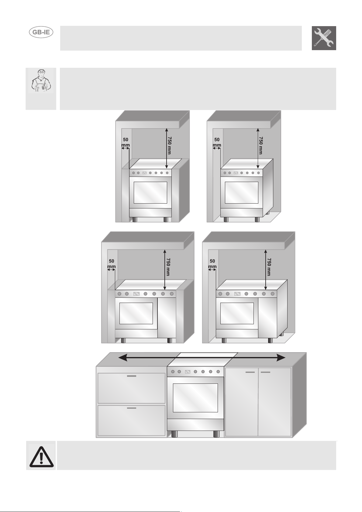
3 INSTALLING THE APPLIANCE
The appliance must be installed by a qualified technician and according to the regulations in force.
Depending on the type of installation, it belongs to class 1 (Fig.A) or to class 2-subclass 1 (Fig.B-C).
This appliance may be installed next to walls, one of which must be higher than the appliance, at a
minimum distance of 50 mm from the side of the appliance, as shown in drawings A and B relative to
the installation classes. Any wall units or ventilation hoods must be at a distance of at least 750 mm
above the appliance.
Instructions for the installer
A
Built-in appliance Free-standing installation
A
Built-in appliance Free-standing installation
B
B
34
C
Appliances equipped with gas cylinder compartment and electric oven can only be installed
as free-standing (see fig. B).
5
3.1 Electrical connection
Make sure the voltage and the cross-section of the power supply line match the specifications
indicated on the identification plate positioned in the storage compartment.
Do not remove this plate for any reason.
If the appliance is connected to the power supply network by means of a fixed connection, install a
multipolar cut-out device on the power supply line, in compliance with installation regulations, located
near the appliance and in an easily reachable position.
Connection to the power supply network may be fixed or with a plug and socket. In the latter case
the plug and socket must be suitable for the cable employed and conform to the regulations in force.
Regardless of the type of connection, the appliance must be earthed. Before connection, make sure
that the power supply line is suitably earthed. Avoid use of adapters and shunts.
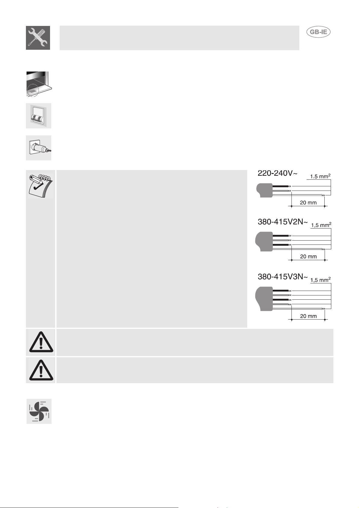
1 - For operation on 220-240V∼: use an H05V2V2-F type
three-core cable (3 x 1.5 mm2 cable).
2 - For operation on 380-415V2N∼: use an H05V2V2-F type
four-core cable (4 x 1.5 mm2 cable);
3 - For operation on 380-415V2N∼: use an H05V2V2-F type
five-core cable (5 x 1.5 mm2 cable);
The end to be connected to the appliance must have an earth
wire (yellow-green) at least 20 mm longer than the other wires.
Instructions for the installer
WARNING: THE VALUES INDICATED ABOVE REFER TO THE CROSS-SECTION OF THE
INTERNAL CONDUCTOR.
Warning: only some of the 90 cm models can be connected with two or three phases.
3.2 Room ventilation
The room containing the appliance should have an air supply in accordance with the standards in
force. The room where the appliance is installed must have enough air flow as required for the
regular combustion of gas and by the necessary air exchange of the same room. The air vents,
protected by grills, must be suitably dimensioned in compliance with the current regulations and
positioned so that no part of them is obstructed.
The cooker must be kept adequately ventilated in order to eliminate the heat and humidity produced
by cooking: in particular, after prolonged use, it is recommended to open a window or increase the
speed of any fans.
3
Make the connection to the gas mains using a rubber hose whose specifications
3.3 Extraction of the combustion products
The combustion products must be extracted by means of hoods connected to a natural draught
chimney whose efficiency is certain or via forced extraction. An efficient extraction system requires
precision planning by a specialist qualified in this area and must comply with the positions and
distances indicated by the regulations. When the job is complete, the installer must issue a certificate
of conformity.
3.4 Connection to gas
3.4.1 Connection with a rubber hose
Installation with a standards-compliant rubber hose must be carried out so that the length of the
piping does not exceed 1.5 metres. Make sure that the hose does not come into contact with moving
parts and that it is not crushed in any way. The inside diameter of the hose must be 8 mm for
LIQUID GAS and 13 mm for NATURAL GAS and CITY GAS.
Verify that all the following conditions are met:
• the hose is fixed to the hose connection with safety clamps;
• no part of the hose is in contact with hot walls (max. 50 °C);
• the hose is not under traction or tension and has no tight curves or twists;
• the hose is not in contact with sharp objects or sharp corners;
• if the hose is not perfectly airtight and leaks gas, do not try to repair it: replace it with a new
hose;
• verify that the hose is not past its expiry date (serigraphed on the hose itself).
CONNECTION USING RUBBER HOSES COMPLYING WITH THE CURRENT REGULATIONS IS
ONLY PERMITTED IF THE HOSE CAN BE INSPECTED ALONG ITS ENTIRE LENGTH.
THE TIGHTENING TORQUE BETWEEN CONNECTIONS THAT INCORPORATE THE GASKET
MUST NOT EXCEED 10Nm
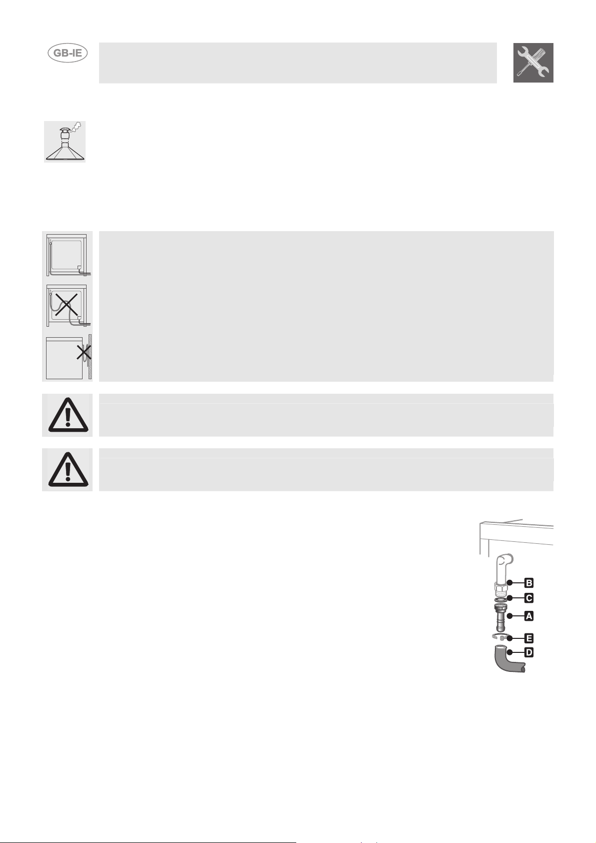
3.4.2 Connection to natural and city gas
comply with the current regulations (verify that the reference standard is stamped
on the hose).
Carefully screw the hose connector A to the gas connector B of the appliance,
placing the seal C between them. Push the rubber hose D onto the hose
connector A and secure it with the clamp E that is compliant with the standard in
force.
Instructions for the installer
36
Instructions for the installer
Open the side compartment and insert a gas cylinder of
3.4.3 Connection to the gas cylinder in the internal compartment of the appliance (only on some models)
max 15 kg. Push one end of the hose onto the hose
connector and secure it with one of the two supplied
clamps. Insert the hose into the gas cylinder
compartment via the hole located at the back of the
appliance following the diagram shown to the side. Push
the other end onto the pressure regulator of the gas
cylinder; secure it in place using the second supplied
clamp. Check for any leaks using a soapy solution,
never with a flame.
For the connection between the cooker and the gas cylinder use a portion of a standards-compliant
hose not less than 1.4 m in length.
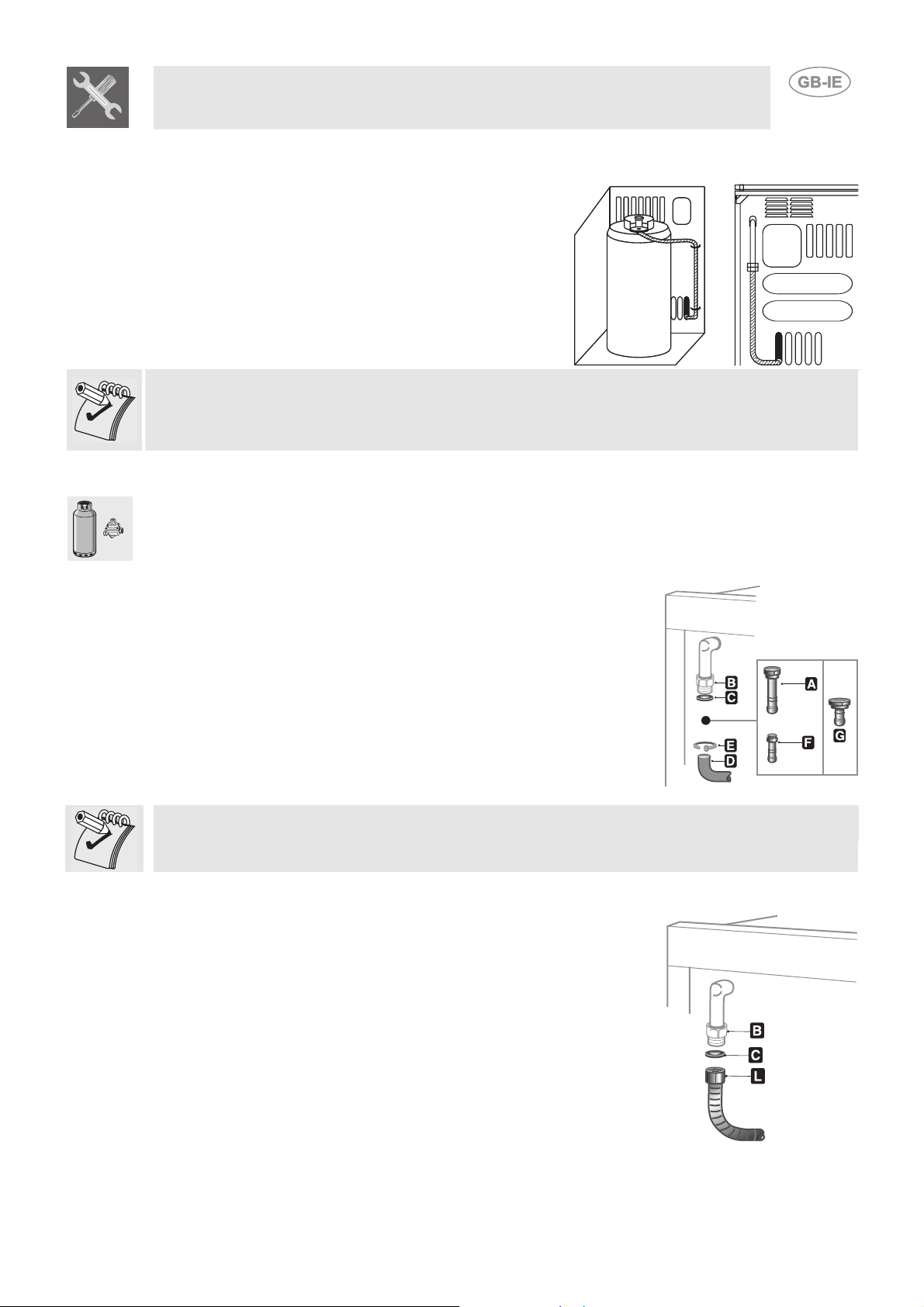
3.4.4 Connection to liquid gas
Use a standards-compliant pressure regulator and carry out the connection to the gas cylinder in
accordance with the regulations in force.
Make sure that the supply pressure complies with the values indicated in the paragraph “3.2/3.3
Burner and nozzle characteristics table”.
Screw the small hose connector F onto the large hose connector A;
connect the block thus obtained to the gas connector B (or use the hose
connector G which must be connected directly to the gas connector B)
and place the seal C in between them. Push the end of the rubber hose
H on to the hose connector A+F (or G) and to the outlet connection of
the pressure reducer on the gas cylinder. Secure the end of the hose H
to the hose connector A+F (or G) with the standards-compliant clamp I.
The hose connector G illustrated is not supplied with the appliance. Only use standards-compliant
hose connectors.
3.4.5 Connection with flexible steel hose (for all types of gas)
This type of connection can be made on both built-in and free-standing
appliances. Only use standards-compliant steel hoses whose length is
not greater than 2 metres. Screw the end of the flexible hose L, with the
seal C positioned in between, to the B threaded ½” external gas
connector (ISO 228-1).
At the end of the installation, check for any leaks with a soapy
solution, never with a flame.
37
4 ADAPTATION TO DIFFERENT TYPES OF GAS
Before carrying out the following operations, disconnect the appliance from the power supply.
Instructions for the installer
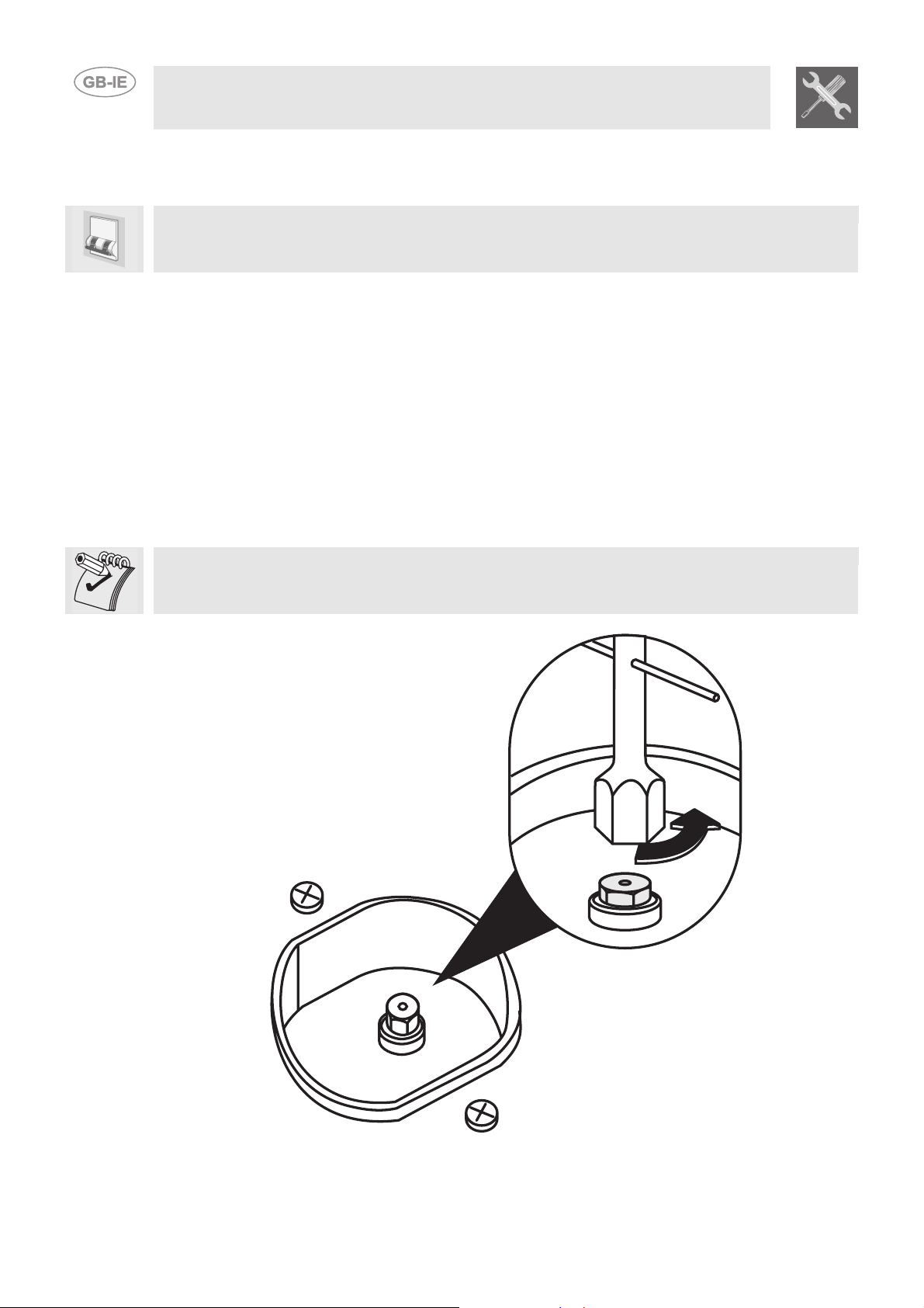
1. Extract the pan stands and remove all the caps and flame-spreader crowns;
The appliance is preset for natural gas G20 (2H) at a pressure of 20 mbar. In case of operation with
other types of gas the burner nozzles must be changed and the minimum flame adjusted on the gas
taps. In addition, in case of the gas oven burner, the primary air must be regulated (3.4.2 Primary air
adjustment for oven burner). To change the nozzles, proceed as described in the following
paragraphs.
4.1 Replacement of the cooking hob nozzles
2. Unscrew the burner nozzles with a 7 mm socket wrench;
3. Proceed to replace the burner nozzles according to the gas to be used (see paragraph “3.2/3.3
Burner and nozzle characteristics table”).
4. Replace the burners in the correct position.
The nozzles for using city gas (G110 – 8 mbar) are available from authorised service centres.
38
Loading...