

Page 1
loqelmelp=mäìë
lйЙк~нбеЦ=fелнкмЕнбзел=
bеЦдблЬ
Page 2

Sirona Dental Systems GmbH
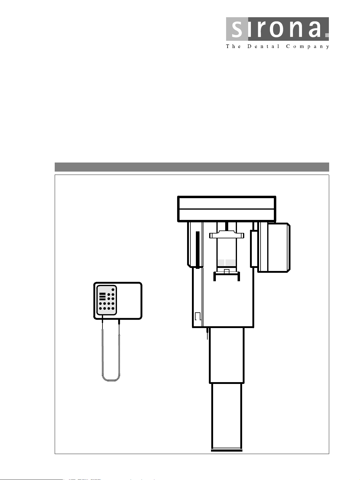
Dear Customer Thank you for purchasing your new ORTHOPHOS Plus
X-ray unit for panorama planigraphy.
Standard radiographs (jaw region), sinus radiographs
(maxillary sinuses) and temporomandibular joint radiographs in digital exposure technique are possible.
For this unit we have provided you with a set of techni-
cal literature. Keep this literature for quick and easy
reference.
In order to protect your rights under Sirona warranty, the
purchaser must register the unit by filling out the War-
ranty Passport provided together with the technician
immediately after installation of the unit.
Read the Operating Instructions to familiarize yourself
with the unit before taking radiographs on the patient.
Please observe the Radiation Protection Regulations
and Warning Notes.
Your
ORTHOPHOS Team
Maintenance To ensure the safety of the patient, the operators and
third parties, equipment inspections and maintenance
work must be carried out at specified intervals in order to
guarantee the operational safety and functional reliability
of your product. (IEC 601-1 / DIN EN 60601-1, etc.).
It is the responsibility of the operator to ensure that the
inspections and maintenance work are carried out.
In the event that the operator fails to fulfil the obligation
to carry out inspections and maintenance work or ignores error messages, Sirona Dental Systems GmbH or
their contracted dealer cannot assume liability for any
damage attributable to this.
2 D3297.201.01.11.02
60 82 023 D3297
Page 3

Sirona Dental Systems GmbH List of Contents
båÖäáëÜ
List of Contents
1 Warning and Safety Notes........................................................................................................ 5
2 Technical Description ............................................................................................................... 8
3 Operating Controls and Displays........................................................................................... 12
3.1 Unit ................................................................................................................. 12
3.2 Control Panel A............................................................................................... 12
3.3 Help LED-displays .......................................................................................... 13
3.4 Multitimer ........................................................................................................ 13
4 Accessories ............................................................................................................................. 14
4.1 Rests and supports......................................................................................... 14
4.2 Hygienic Protective Covers............................................................................. 15
4.3 Service Tools.................................................................................................. 15
5 Exposure Programs ................................................................................................................ 16
5.1 P 1 Program.................................................................................................... 16
5.2 P 2 Program.................................................................................................... 16
5.3 P3 Program..................................................................................................... 17
5.4 P4 Program..................................................................................................... 17
5.5 P5 Program..................................................................................................... 18
5.6 P6.1 / P6.2 Program ....................................................................................... 18
5.7 P7.1 / P7.2 Program ....................................................................................... 19
5.8 P8 Program..................................................................................................... 19
5.9 P9 Program..................................................................................................... 20
5.10 P10 Program................................................................................................... 20
5.11 P11 Program................................................................................................... 21
5.12 P12 Program................................................................................................... 21
5.13 P13 Program................................................................................................... 22
5.14 P14 Program................................................................................................... 22
5.15 P15 Program................................................................................................... 23
5.16 P16 Program................................................................................................... 23
6 Operating.................................................................................................................................. 24
6.1 Preparing the Exposure.................................................................................. 24
Loading the Film Cassette ....................................... 24
Insert Accessories.................................................... 24
Contact Spacer and Head Positioner....................... 24
Switching ON the Unit.............................................. 25
Primary Diaphragm .................................................. 25
Digital Displays......................................................... 25
6.2 Positioning the Patient .................................................................................... 27
Preparations............................................................. 27
Exposure with Chin Rest and Bite Block.................. 27
The Frankfurt horizontal FH ..................................... 29
Digital displays ......................................................... 29
Exposure with Chin Rest and Bar ............................ 30
60 82 023 D3297
D3297.201.01.11.02
3
Page 4

List of Contents Sirona Dental Systems GmbH
Exposure with Bite Block or Contact Segment without
Chin Support ............................................................ 31
. . . with Bite Block.................................................... 31
. . . with Contact Segment ........................................ 31
The Frankfurt Horizontal FH..................................... 32
Digital displays ......................................................... 32
Exposures of the Temporomandibular Joint, P4 – P9
Programs with Head Positioner................................ 33
6.3 Final Preparations........................................................................................... 34
Selecting the Exposure Program.............................. 34
Automatic Exposure Selection AES (ABV)............... 35
Select Exposure Data............................................... 35
Anomaly Button A..................................................... 36
6.4 Releasing the Exposure.................................................................................. 37
Interrupting the Exposure ......................................... 38
Automatic Exposure Blockage ................................. 38
Error Message E... ................................................... 38
7 Programming ........................................................................................................................... 39
Programming Procedure .......................................... 39
Adjustment of the Exposure ..................................... 40
8 Help Messages H3................................................................................................................... 41
9 Program Values ....................................................................................................................... 42
9.1 Program Values .............................................................................................. 42
10 Care the surfaces .................................................................................................................... 43
11 List of Error Messages............................................................................................................ 44
12 Inspection and Maintenance .................................................................................................. 46
12.1 Annual inspection performed by the operator or other authorized personnel . 46
12.2 Maintenance performed by the service technician.......................................... 46
12.3 Checking image quality................................................................................... 46
4 D3297.201.01.11.02
60 82 023 D3297
Page 5

ÉåÖäáëÜ
Sirona Dental Systems GmbH 1 Warning and Safety Notes
1 Warning and Safety Notes
Labeling of warning and safety information In order to prevent injury to persons and damage to the
equipment you must also read the warning and safety
notes given in these Operating Instructions. These are
emphasized with CAUTION and WARNING.
Symbols used Observe accompanying documents
(on name plate)
Intended use This unit has been designed for use in creating pano-
rama radiographic exposures.
This unit must not be used in areas where there is a risk
of explosion.
Maintenance and repair As manufacturers of electromedical equipment we can
assume responsibility for safety-related performance of
the equipment only if maintenance and repair are carried out only by us or agencies we have authorized for
this purpose, and if components affecting safe operation
of the unit are replaced with original spare parts.
We suggest that you request a certificate showing the
nature and extent of the work performed from those who
carry out such work; it must contain any changes in rated
parameters or working ranges (if applicable), as well as
the date, the name of the company and a signature.
Modifications to the system Modifications to this system which could impair the
safety of operators, patients or third persons are prohibited by legal provisions!
For reasons of product safety, this product may be
operated only with original Sirona accessories or accessories manufactured by third parties expressly approved
by Sirona. The user is responsible for dangers resulting
from the use of non-approved accessories.
If any devices not approved by Sirona are connected,
they must comply with the applicable standards:
IEC 60950 for information technology equipment (e.g.
PCs), and IEC60601-1 for medical electrical equipment.
Ventilation slots Under no circumstances may the ventilation slots on the
unit be covered, since otherwise the air circulation will be
obstructed.
Do not spray disinfectants or other similar products into
the ventilation slots.
X-rays of patients X-rays of patients must be taken only when the system
works without errors.
The system may only be operated by skilled or properly trained personnel.
60 82 023 D3297
D3297.201.01.11.02
5
Page 6

1 Warning and Safety Notes Sirona Dental Systems GmbH
The movements of the unit must not be obstructed by
physical constitution nor clothing, dressings, wheelchairs or hospital beds!
Do not leave the patient unattended in the unit.
Electromagnetic compatibility (EMC) Medical electrical devices are subject to special precau-
tionary measures regarding EMC. They must be
installed and operated as specified in the document
"Installation Requirements".
Information on avoiding, recognizing and eliminating
unintended electromagnetic effects: The ORTHOPHOS
Plus acquisition unit is a Class B device (classified
according to CISPR 11, EN 60601-1-2: 2001 based on
IEC 60601-1-2). This system may be operated in a residential area.
Portable and mobile HF communication devices can
influence medical electrical equipment. The use of
mobile telephones in the practice or hospital area therefore must be prohibited.
Precautionary measures when switching on the
unit
Following extreme temperature fluctuations, condensation may occur; therefore please do not switch on the
system until it has reached normal room temperature
(see chapter “Technical Description”).
No patient may be positioned in the unit during poweron.
In case of an error that requires switching off and subsequent switching on of the unit, the patient must be
removed from the unit before switching it on again at the
latest!
Emergency Stop If parts of the unit contact the patient during the rotational
movement , let go of the exposure release button (XRay) immediately and stop the unit by actuating the unit
main switch or an Emergency Stop switch!
Disturbance of electronic devices worn on the
patient’s body.
To prevent the malfunctioning of electronic devices and
data storage devices, e.g. radio-controlled watches,
telephone cards, etc., these objects must be removed
prior to X-raying.
Radiation protection The valid radiation protection regulations must be
observed.
The operator should move as far away from the X-ray
tube assembly as allowed by the coiled cable of the
exposure release button.
The statutory radiation protection equipment must be
used.
With the exception of the patient, no other persons
without radiation protection are allowed to stay in the
room. In exceptional cases, a third person may provide
assistance, but not the practice staff. During the whole
exposure, visual contact with the patient and the unit
must be maintained.
60 82 023 D3297
6 D3297.201.01.11.02
Page 7

ÉåÖäáëÜ
Sirona Dental Systems GmbH 1 Warning and Safety Notes
In case of malfunctions, interrupt the exposure immediately by releasing the exposure release button.
Hygiene information The protective covers must be exchanged for each new
patient and the sterilizable accessories must be sterilized to prevent any transmission of infective agents
which might cause serious illnesses.
Suitable hygienic measures must be taken to prevent
cross contamination among patients, users and other
persons.
Dismantling and reassembly For dismantling and reassembly of the device, proceed
according to the Installation Instructions for new installation in order to guarantee the operability and stability of
the system.
Disposal It generally applies that any disposal of this product must
comply with the relevant national regulations. Please
observe the regulations applicable in your country.
Within the European Economic Community, Council
Directive 2002/96/EU (WEEE) requires environmentally
sound recycling/disposal of electrical and electronic
devices.
Your product is marked with the adjacent symbol. Disposal of your product with domestic
refuse is not compatible with the objectives of environmentally sound recycling/disposal.
The black bar underneath the "garbage can" symbol
means that it was put into circulation after Aug. 13, 2005.
(see EN 50419:2005)
Please note that this product is subject to Council Directive 2002/96/EU (WEEE) and the applicable national law
of your country and must be recycled or disposed of in
an environmentally sound manner.
The X-ray tube assembly of this product contains a
tube with a potential implosion hazard, a small amount
of beryllium, a lead lining and mineral oil.
Please contact your dealer if final disposal of your product is required.
60 82 023 D3297
D3297.201.01.11.02
7
Page 8
2 Technical Description Sirona Dental Systems GmbH
2 Technical Description
Nominal line voltage: 208V / 230V AC
Permissible fluctuation with 230 V:
with 208 V:
Nominal current: 12A
Nominal frequency: 50/60Hz
Power line resistance: max. 0,8Ohm
Fuse at the distribution panel: 16A slow blow
Rating: 2,8kVA
Tube voltage: 60 – 90kV
Tube current: 9 –16mA
Curve form of high voltage: High frequency, multipulse
Program duration: see page 42
Exposure time: see page 42
Reproduction scale:
Focus size, according to IEC 336,
measured in central ray:
+6, –10%
±10%
Residual ripple ≤ 4kV
With P1 program, medium mandibular arch (plane center) ca.
1:1,19. The image at the image receiver is approximately 19%
larger than the real proportions.
0,5mm
Focus marking:
Automatic exposure blockage (see page 38): The duration of the exposure blockage (cool-off period) depends
on the kV/mA step set and the actually triggered radiation time.
Depending on the tube load, pause times between 8s and 300s
are set automatically.
Example: For P1 program with exposure data 80kV/14mA and a
radiation time of 14.1s a pause of 255s results.
Equipment of protective class I
Protection against electric shock:
Protection against penetration of water: Ordinary equipment (without protection)
Type B equipment
60 82 023 D3297
8 D3297.201.01.11.02
Page 9
ÉåÖäáëÜ
Sirona Dental Systems GmbH 2 Technical Desc ription
Year of manufacture (on the name plate)
Mode of operation: Continuous operation
Long time power rating 60W
Ta r ge t ma t er ia l Wo l fr a m
Loading factors concerning leakage radiation 0,57mA / 90 kV
Source - Image receptor distance 497 mm
Transport and storing temperature: -40°C – +70°C (-40°F – 158°F)
Relative humidity: 10% – 95%
Permissible operating temperature: According to IEC 601-1 between +10°C and +40°C
(50°F – 104°F)
ORTHOPHOS Plus is in compliance with EN 60 601-2-7 / 1998
ORTHOPHOS Plus is in compliance with IEC 601-2-28 / 1993
ORTHOPHOS Plus is in compliance with IEC 601-1-3 / 1994
Original language: german
0123
This product is provided with a CE marking in accordance with the regulations stated in the Directive 93/42/
EEC of June 14, 1993 concerning medical products.
Reg. No.: China
SFDA (I) 20053301583
60 82 023 D3297
D3297.201.01.11.02
9
Page 10
2 Technical Description Sirona Dental Systems GmbH
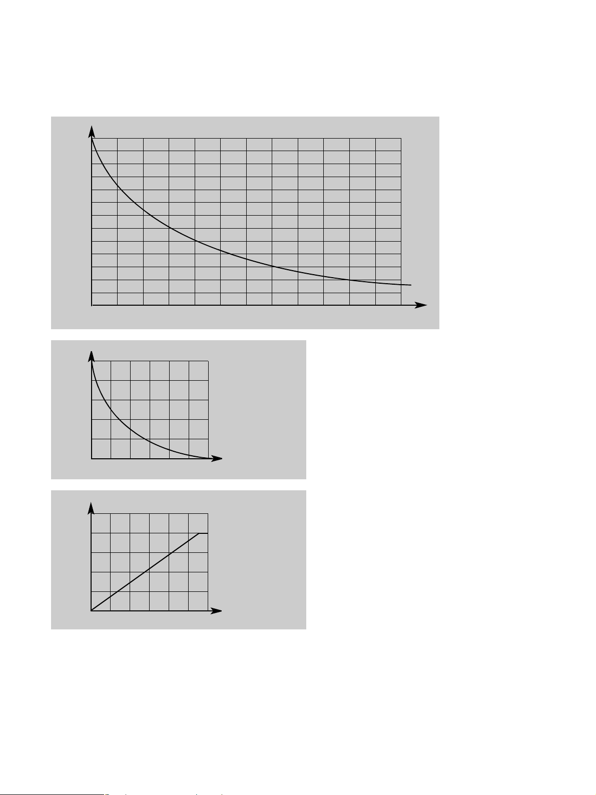
Cooling curve for the tube housing:
4
HUx10
1HU = 1,35 Joule
130
120
110
100
90
80
70
60
50
40
30
20
10
t
0 60 120 180 240 300 360 420 480 540 600 660 720
Anode cooling caracteristic:
25
HUx10
3
1HU = 1,35 Joule
20
15
10
5
t
012 3 4 5 6
3
HUx10
1HU = 1,35 Joule
min
Heating curve for tube housing:
1350
min
t
012 3 4 5 6
h
60 82 023 D3297
10 D3297.201.01.11.02
Page 11

ÉåÖäáëÜ
Sirona Dental Systems GmbH 2 Technical Desc ription
Reference axis
Reference axis
7°
10°
Anode angle
60 82 023 D3297
D3297.201.01.11.02
11
Page 12
3 Operating Controls and Displays Sirona Dental Systems GmbH
3 Operating Controls and Displays
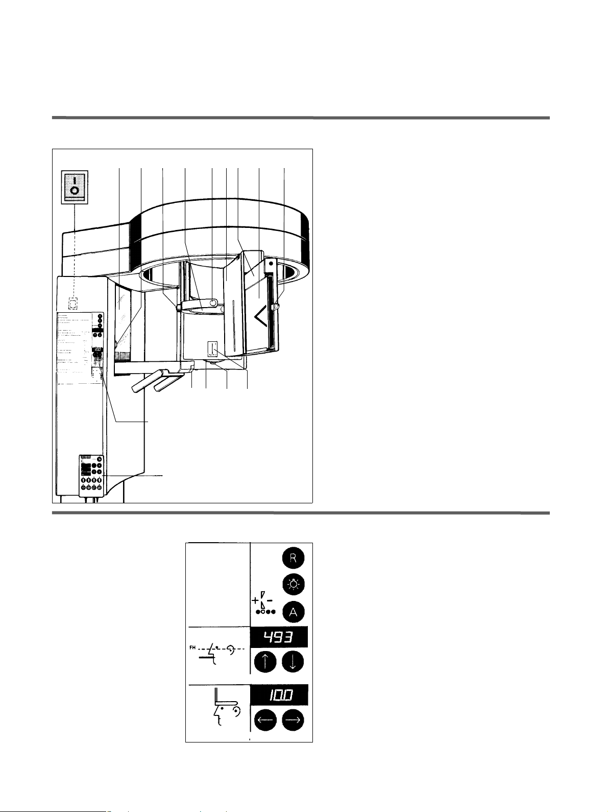
3.1 Unit
234 5 6781 9 10
11 12 13 14
A
1 Main switch
2 Patient positioning mirror
3 Height adjustment for the FH light line
4 Adjusting knob for temple supports
5 Forehead support
6 Temple supports
7 Cassette holder
8 Cassette carriage
9 Film cassette
10 Film cassette stop
11 Button for removing bite block
12 Diaphragm wheel
13 Locking button
14 Diaphragm
Multitimer
3.2 Control Panel A
Return button R
Light localizer ON / OFF
Anomaly button A + – with LED display
Height adjustment display in mm
Height adjustment
Forehead support adjustment display in mm
Forehead support adjustment
← towards column / away from column →
12 D3297.201.01.11.02
60 82 023 D3297
Page 13
ÉåÖäáëÜ
Sirona Dental Systems GmbH 3 Operating Controls and Displays
3.3 Help LED-displays
See the inside of the door for a list of appropriate H3 help
messages (see page 41).
13
14
15
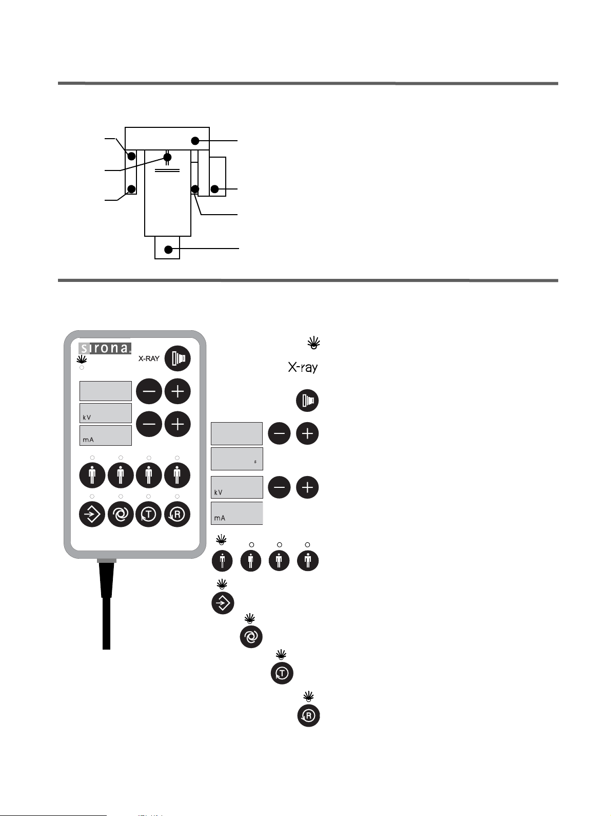
3.4 Multitimer
16
17
18
19
13 Cassette holder not in position
14 Forehead support position
15 Exposed film inserted
16 X-ray tube position
17 Cool-down interval
18 Diaphragm adjustment
19 Height adjustment
”Unit ON” LED
PI
62
I6
PI
I4.I
62
I6
X-ray ON indicator
Exposure button
Digital display for exposure program / exposure time
with – + buttons for exposure programs
Digital display for kV/mA values
with – + buttons for kV/mA matched values
Patient symbols
programmed kV/mA values
Memory program button
kV/mA matched values
AES button (Automatic Exposure Selection)
Rotation test button T
without radiation
60 82 023 D3297
D3297.201.01.11.02
Return button R
The LED blinks when the system is not ready (ReadyLED).
13
Page 14
4 Accessories Sirona Dental Systems GmbH
4 Accessories
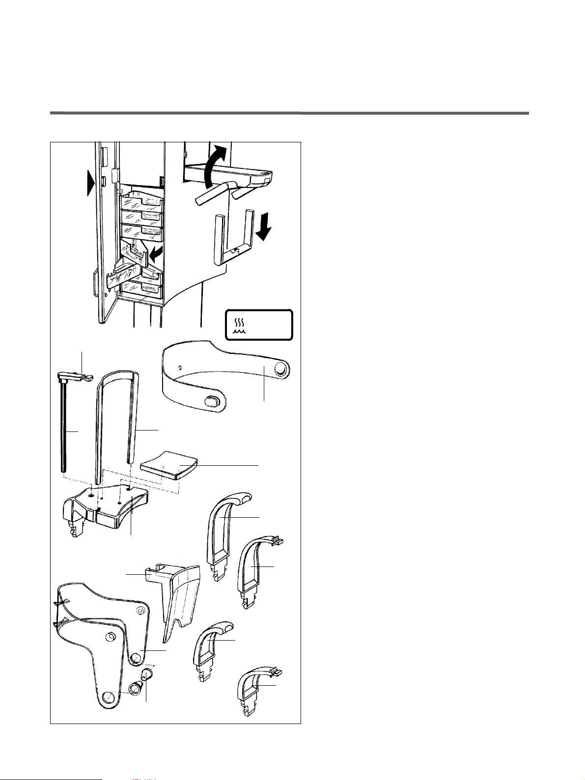
4.1 Rests and supports
The receptacles behind the door are for the storage of
accessories and hygienic protective covers.
Press
shortly
to open.
Handles and * marked accessories can be sterilized.
Sterilize only in an autoclave at 135°C, 2.1 bar
(275°F, 30PSI).
Untightened handles can be removed for sterilization as
shown.
For tightened handles, please use the hygienic protective covers shown on the next page.
For reorders:
A* Forehead support strip
(5 pcs) Order No. 89 21 835
E*
F
135° C
275° F
A*
C*
D*
H*
B*
L
G*
B* Chin rest complete,
incl. 5xE, 1xF, C, D, R, S
Order No. 18 88 762
C* Bar for chin rest
Order No. 59 61 461
D* Intermediate piece
Order No. 14 49 227
E* Bite block
(10 pcs) Order No. 18 88 887
F Stick for bite block
(5 pcs) Order No. 18 88 895
G* Standard yellow bite block
(5 pcs) Order No. 89 21 843
H* Standard yellow contact segment
for subnasals
(5 pcs) Order No. 89 31 545
J Head positioner complete,
incl. 4xK
Order No. 18 88 770
K* Ear fixation
(10 pcs) Order No. 18 88 838
L Contact spacer
Order No. 33 10 336
M* Bite block blue, for sinus exposures
(5 pcs) Order No. 89 21 850
J
N*
M*
N* Contact segment, blue,
for subnasals with sinus and paranasal
tomographic exposures
(5 pcs) Order No. 89 31 552
K*
14 D3297.201.01.11.02
60 82 023 D3297
Page 15

ÉåÖäáëÜ
Sirona Dental Systems GmbH 4 Accessories
4.2 Hygienic Protective Covers
Before each exposure, the hygienic protective covers
(disposable) should be attached.
For better illustration of the components, the following
figures are shown without the hygienic protective covers.
For orders:
P For forehead support and handles
(500 pcs) Order No. 33 14 098
P
S
R
Dimensions:
210mm (140 mm) x 57 mm
R For chin rest
(100 pcs) Order No. 59 32 603
Dimensions: 75mm x 60mm
S For bite block
(500 pcs) Order No. 33 14 072
Dimensions: 43mm x 21mm
T For bite block and contact segment
(500 pcs) Order No. 33 14 080
Dimensions: 80mm x 40mm
4.3 Service Tools
1
T
4
3
Tools supplied with the unit and needed for the maintenance and/or service must remain with the unit.
(Adjustment set).
1 Special wrench
Order No. 52 43 605
2 Needle phantom
Order No. 89 31 925
3 Te s t b lo c k
2
Certified component of the unit.
4 Beam alignment tool
Order No. 89 31 800
60 82 023 D3297
D3297.201.01.11.02
15
Page 16

5 Exposure Programs Sirona Dental Systems GmbH
5 Exposure Programs
5.1 P 1 Program
Complete standard exposure
1
1
• Chin support with rod and bite block or bar
or
yellow bite block or contact segment.
• Working area forehead support 00.0 - 30.0
Head inclination with FH.
• Automatic selection of section shape via temple
Film PAN
15x30 cm
6x12 in.
PAN
SID = 49.7 cm
yellow
1
support setting for different mandibular arches.
Radiation time dependent on adjusted width of temple supports.
• Manual compensation
for anatomical relationships (protrusion, retrusion)
by anomaly button A (see page 36).
• Automatic Exposure Selection AES is possible (see
page 35)
i
NOTE
L on the film means the left half of the cranium.
5.2 P 2 Program
Film PAN
15x30 cm
6x12 in.
PA N
SID = 49.7 cm
yellow
Standard exposure, restricted to the teeth
(without ascending branches).
2
1
• Chin support with rod and bite block or bar
or
yellow bite block or contact segment.
• Working area forehead support 00.0−30.0
1
Head inclination with FH.
• Automatic selection of section shape via temple
support setting for different mandibular arches.
Radiation time dependent on adjusted width of temple supports.
• Manual compensation
for the anatomical relationships (protrusion, retrusion) by anomaly button A (see page 36).
16 D3297.201.01.11.02
60 82 023 D3297
Page 17

ÉåÖäáëÜ
Sirona Dental Systems GmbH 5 Exposure Programs
5.3 P3 Program
Sinus maxillaris
(2-on-1 film subdivision)
3
1
• Blue bite block or contact segment.
• Forehead support strip with attachment down (see
page 24).
• Working area forehead support 10.0-30.0
Film PAN
15x30 cm
6x12 in.
PA N
SID = 49.7 cm
1
Head inclination with FH.
• Only release trigger when Ready-LED flashes.
(radiation is released automatically twice in a row).
5.4 P4 Program
Film PAN
15x30 cm
6x12 in.
PAN
SID = 49.7 cm
blue
Lateral exposure of the temporo-mandibular joints
(ascending branches)
4
6
1
• Insert head positioner (see page 24).
• Working area forehead support 06.0−30.0
Recommended position of forehead support 06.0.
Head inclination with the aid of FH.
1
60 82 023 D3297
D3297.201.01.11.02
Headpositioner
17
Page 18

5 Exposure Programs Sirona Dental Systems GmbH
5.5 P5 Program
Posterior/anterior exposures of the temporomandibular joints
5.6 P6.1 / P6.2 Program
Film PAN
15x30 cm
6x12 in.
Headpositioner
PAN
SID = 49.7 cm
1
5
20
1
• Insert head positioner (see page 24)
• Working area forehead support 00.0−27.0
Recommended position of forehead support 20.0
To avoid superimpositions to a large extent, head in-
clination relative to FH toward anterior.
Lateral exposures of the temporo-mandibular joints
with closed and open mouth
(4 exposures on 1 film)
6
6
1
• Insert head positioner (see page 24).
• Working area forehead support 00.0−30.0
P6.1 P6.1P6.2 P6.2
Recommended position of forehead support 06.0
Head inclination with the aid of FH.
P6.1
Film PAN
15x30 cm
6x12 in.
PAN
SID = 49.7 cm
1
P6.1 Outer Image:
Geschlossener Mund
P6.2 Inner Image:
Open mouth
• Actuate P6.1
After P6.1 is completed, the unit automatically returns to the initial position.
• Have the patient open his mouth and actuate P6.2.
Headpositioner
P6.2
18 D3297.201.01.11.02
60 82 023 D3297
Page 19

ÉåÖäáëÜ
Sirona Dental Systems GmbH 5 Exposure Programs
5.7 P7.1 / P7.2 Program
Posterior/anterior exposures of the temporomandibular joints with closed and open mouth
(4 exposures on 1 film)
7
20
1
• Insert head positioner (see page 24)
• Working area forehead support 00.0−27.0.
Recommended position of the forehead support
P7.1 P7.1P7.2 P7.2
20.0
To avoid superimpositions to a large extent, head in-
Film PAN
15x30 cm
6x12 in.
PA N
SID = 49.7 cm
1
clination relative to FH toward anterior.
P7.1 Outer Image:
Closed mouth
P7.2 Inner Image:
Open mouth
P7.1
•Actuate P7.1.
After P7.1 is completed, the unit automatically returns to the initial position.
• Have the patient open his mouth and actuate P7.2.
Headpositioner
P7.2
5.8 P8 Program
ACBC BA
C B A
Film PAN
15x30 cm
6x12 in.
Headpositioner
PAN
SID = 49.7 cm
1
Multi-layer exposures, lateral exposures of the temporomandibular joints
(6 exposures on 1 film)
8
0
1
• Insert head positioner (see page 24)
• Working area forehead support 00.0-30.0
Recommended position of the forehead support
00.0
Head inclination with the aid of FH.
60 82 023 D3297
D3297.201.01.11.02
19
Page 20

5 Exposure Programs Sirona Dental Systems GmbH
5.9 P9 Program
Multi-layer exposures, posterior/anterior exposures
of the temporomandibular joints
(6 exposures on 1 film)
ACBC BA
Film PAN
15x30 cm
6x12 in.
1
9
1
• Insert head positioner (see page 24)
• Working area forehead support 00.0-27.0
Recommended position of forehead support 20.0
To avoid superimpositions to a large extent, head in-
clination relative to FH toward anterior.
20
C
B
A
5.10 P10 Program
PAN
SID = 49.7 cm
Headpositioner
Film PAN
15x30 cm
6x12 in.
12,7x30,5 cm
5x12 in.
STATUS
2
SID = 49.7 cm
Standard exposure (Status),
preferred mode for children
10
2
• IMPORTANT!
Adjust diaphragm 2.
• Yellow bite block or contact segment.
• Working area forehead support 00.0−30.0
Head inclination with the aid of FH.
• Automatic selection of section shape via temple
support setting for different mandibular arches.
Radiation time dependent on adjusted width of temple supports.
• Manual compensation
for anatomical relationships (protrusion, retrusion)
by anomaly button A.(see page 36)).
yellow
20 D3297.201.01.11.02
60 82 023 D3297
Page 21

ÉåÖäáëÜ
Sirona Dental Systems GmbH 5 Exposure Programs
5.11 P11 Program
with constant 1.25-fold magnification
e.g. for implantology
11
1
• Chin support with rod and bite block or bar
or
yellow bite block or contact segment.
• Working area forehead support 00.0−30.0
Head inclination with the aid of FH.
Film PAN
15x30 cm
6x12 in.
PAN
SID = 49.7 cm
1
• Automatic selection of section shape via temple
support setting for different mandibular arches
Radiation time dependent on adjusted width of temple supports.
• Manual compensation
for anatomical relationships (protrusion, retrusion)
by anomaly button A (see page 36).
5.12 P12 Program
yellow
Film PAN
15x30 cm
6x12 in.
PAN
SID = 49.7 cm
Display of the anterior teeth area with larger section
thickness
e.g. for implantology
12
1
• Chin support with rod and bite block or bar
or
yellow bite block or contact segment.
• Working area forehead support 00.0-27.0
Head inclination with the aid of FH.
1
60 82 023 D3297
D3297.201.01.11.02
yellow
21
Page 22

5 Exposure Programs Sirona Dental Systems GmbH
5.13 P13 Program
Paranasal tomographic exposures
e.g. Blow-out fractures
13
1
• Blue contact segment insert subnasal (see page 31)
• Insert head positioner without ear fixation (see
page 24)
Film PAN
15x30 cm
6x12 in.
PAN
SID = 49.7 cm
1
blue
• Working area forehead support 00.0−30.0
Patient head max. reclined.
5.14 P14 Program
Headpositioner
Film PAN
15x30 cm
6x12 in.
PA N
SID = 49.7 cm
1
Standard exposure, left half side
14
1
• Chin support with rod and bite block or bar
or
yellow bite block or contact segment.
• Working area forehead support 00.0−30.0
Head inclination with the aid of FH.
• Automatic selection of section shape via temple
support setting for different mandibular arches.
Radiation time dependent on adjusted width of temple supports.
• Manual compensation
for anatomical relationships (protrusion, retrusion)
by anomaly button A (see page 36).
yellow
22 D3297.201.01.11.02
60 82 023 D3297
Page 23

ÉåÖäáëÜ
Sirona Dental Systems GmbH 5 Exposure Programs
5.15 P15 Program
Standard exposure, right half side
15
1
• Chin support with rod and bite block or bar
or
yellow bite block or contact segment.
• Working area forehead support 00.0−30.0
Head inclination with the aid of FH.
• Automatic selection of section shape via temple
support setting for different mandibular arches.
Film PAN
15x30 cm
6x12 in.
PA N
SID = 49.7 cm
1
Radiation time dependent on adjusted width of temple supports.
• Manual compensation
for anatomical relationships (protrusion, retrusion)
by anomaly button A (see page 36).
yellow
5.16 P16 Program
CABA BC
C
Film PAN
15x30 cm
6x12 in.
PAN
SID = 49.7 cm
1
B
Multi-layer exposures in the buccal teeth area
(6 exposures on 1 film)
16
1
• Yellow bite block or contact segment.
• Working area forehead support 05.0−30.0
• Mandibular margin horizontally.
60 82 023 D3297
D3297.201.01.11.02
A
yellow
23
Page 24

6 Operating Sirona Dental Systems GmbH
6 Operating
6.1 Preparing the Exposure
Loading the Film Cassette
Treat the film cassette and intensifier screen with care to
avoid scratching the screen or denting the cassette
housing.
Opening the cassette: Push the locks A forward as
shown and lift up lever B.
Then you can place film in the cassette.
Closing the cassette: Press the cover down uniformly
on both sides until the locks click.
Insert Accessories
• Insert Chin Rest or Bite Block up to stop.
For application see chapter ”Exposure Programs”.
• Press button (11) to remove.
• Open Temple Supports with button (4)
A
A
B
4
• Insert Forehead Support Strip A
A
• with attachment A ↑ up for adults.
• with attachment A ↓ down for patients with smaller
heads.
11
Contact Spacer and Head Positioner
• Insert Contact Spacer L
Application for temporomandibular jaw exposure programs P4 – P9.
Always place the contact spacer where, as a result of
anatomical features, with correct head positioning there
is no contact with the forehead (no 3-point fixing).
• After positioning the head, press the contact spacer
onto the tube and push it down to the forehead contact.
• Insert Head Positioner J
• Open temple supports,
• Insert head positioner up to stop.
Application for temporomandibular jaw exposure programs P4–P9 and for paranasal tomography P13, but
without ear fixation.
24 D3297.201.01.11.02
60 82 023 D3297
Page 25

ÉåÖäáëÜ
Sirona Dental Systems GmbH 6 Operating
Switching ON the Unit
• Depress the main switch (1) into the I position and
wait 1 minute.
• The LED in the upper left corner of the Multitimer will
light up.
• The unit adjusts itself automatically:
• The rotating unit moves a little to the right and left.
1
• The forehead support moves to basic position 10.0.
• The cassette carriage moves to the initial position.
CAUTION
When switching on the unit, there must not be a patient
positioned in the unit.
If a fault occurs which requires switching the unit off and
then back on again, the patient must be taken out of the
unit at the latest before switching it on again!
Primary Diaphragm
Depending on the exposure program selected, diaphragm 1 or 2 is required. Diaphragm 2 is preferred for
children.
Adjust diaphragm
by pressing button (11) and rotating the diaphragm
wheel (10) up to the stop.
The diaphragm number appears in the upper right corner of the window.
11 10
493
I0.0
When the diaphragm moved into place is not suitable for
the program preselected on the Multitimer or when the
diaphragm is not correctly locked into place, Help LED
(18) for diaphragm setting flashes on control panel A.
Lock correct diaphragm into place, the LED (18) extinguishes.
18
Digital Displays
At the control panel A
• The mm value of height adjustment between 000
and 640 from the last patient.
• The basic forehead support value of 10.0 mm.
• or a help message H3... or an error message E... is
displayed, same as on the Multitimer
(see page 41 and page 44).
60 82 023 D3297
D3297.201.01.11.02
25
Page 26

6 Operating Sirona Dental Systems GmbH
A
B
PI
62
I6
Exposure key
C
Multitimer
At the Multitimer the program and exposure parameters
employed with the last patient appear.
A shows you the exposure program sequentially and
the respective maximum exposure time.
B gives you the kV/mA matched value pair.
The LED over the respective patient symbol
lights up.
C The LED over the return button R blinks.
Move the rotating unit into place for patient positioning
by tapping one of the return buttons R.
Help LED (16) for the tube unit position extinguishes
on control panel A.
i
NOTE
You can release a test rotation without radiation via
the exposure button after having pressed the T button.
16
26 D3297.201.01.11.02
60 82 023 D3297
Page 27

ÉåÖäáëÜ
Sirona Dental Systems GmbH 6 Operating
6.2 Positioning the Patient
Preparations
• Have the patient remove all metallic objects such
as glasses and jewelry, from the head and neck regions. Have him take out removable dentures.
• Physical constitution, clothing, bandages etc. must
not interfere with the functioning of the unit!
Perform a test run with the T button (see page 26).
• Swing out the cassette holder (7) fully.
• Insert chin rest, bite block/contact segment or head
positioner, see ”Exposure Programs” chapter”.
Exposure with Chin Rest and Bite Block
7
• With programs P1, P2, P10, P11, P12, P14 and P15,
move forehead support to the 00.0 position by actuating the ← key.
For the forehead support setting for the other programs
refer to the ”Exposure Programs” chapter”.
• Have the patient stand in front of the mirror.
•Using the ↑ and ↓ buttons, adjust unit height so that
the chin of the patient and the chin rest match up.
Motoric movement is accompanied by an acoustic signal.
i
NOTE
The height adjustment motor starts up slowly and then
picks up speed.
• Have the patient place his chin on the chin rest and
grip the handles.
• Swing in the bite block.
• Have the patient bite the bite block at the indentation
(the upper anterior teeth should be directly in the indentation, and the lower anterior teeth should be
moved forward up to the stop).
60 82 023 D3297
D3297.201.01.11.02
27
Page 28

6 Operating Sirona Dental Systems GmbH
CAUTION
Make certain the spine is tilted slightly as shown.
This moves the patient's cervical vertebrae into a more
stretched out position.
The cervical vertebrae ”stretched out” ensures that the
area of the anterior teeth is not over exposed.
In special cases, it is also possible to position for sitting
patients.
CORRECT
INCORRECT
28 D3297.201.01.11.02
60 82 023 D3297
Page 29

ÉåÖäáëÜ
Sirona Dental Systems GmbH 6 Operating
• Swing out the mirror by pressing on field A.
• Position the patient's head so that the biting sur-
face is slightly tilted forward.
• Switch on the light localizer by pressing the key on
the control panel. The light localizer facilitates correct positioning of the patient.
i
NOTE
The light localizer turns off automatically after about 2,5
minutes.
FH
B
3
A
5
4
6
The Frankfurt horizontal FH
light beam should reflect from the plane passing through
the lower margins of the orbits and the upper margins of
the external auditory orifices.
The knob (3) can be used to vertically adjust the FH line.
• Finely adjust the head inclination for the FH line adjustment by tapping the buttons ↑ or ↓ for vertical
unit movement.
• Line up the middle of the patient's face with the cen-
tral light line.
•Press the → button for movement away from the col-
umn until the forehead support (5) touches the patient's forehead.
i
NOTE
When the temple support position is not suitable for the
preselected exposure program, Help LED (14) flashes.
Run the temple support into the correct position (see exposure programs), LED (14) extinguishes.
• Position the temple supports (6) firmly with knob (4).
5
4
60 82 023 D3297
D3297.201.01.11.02
6
14
i
NOTE
With programs P1, P2, P10, P11, P14 and P15, the radiation time changes as a function of the width of the temple supports.
• Swing back the mirror by pressing on field B.
• Have the patient take a small step toward the col-
umn. Recheck the FH-line position.
• Have patient press tongue against roof of palate.
Digital displays
The reference values for height and forehead support,
which should be noted for later exposures with this
patient, are displayed on the control panel.
29
Page 30

6 Operating Sirona Dental Systems GmbH
Exposure with Chin Rest and Bar
For patients without anterior teeth
• Remove bite block with holding rod and insert bar as
shown (bow facing column).
• Ensure that the upper and lower jaws are lined
up with each other.
This is facilitated by a cotton roll.
• Proceed as in the case of exposures with chin rest
and bite block.
Deviation:
The patient places his chin on the chin rest.
• To position the head optimally for tomographic exposures, the bar should be just under the patient's
nose.
• If there are still anterior teeth in the lower jaw, place
the bar between chin and lower lip.
• Have patient press tongue against roof of palate.
30 D3297.201.01.11.02
60 82 023 D3297
Page 31

ÉåÖäáëÜ
Sirona Dental Systems GmbH 6 Operating
Exposure with Bite Block or Contact Segment
without Chin Support
• With programs P1, P10, P14 and P15, move the
forehead support to the 00.0 position by actuating
the ← key.
For the forehead support setting for the other programs
refer to the ”Exposure Programs” chapter.
• Have the patient stand in front of the mirror.
. . . with Bite Block
•Using the ↑ and ↓ buttons, adjust unit height so that
the bite block and the anterior teeth match up.
• Have the patient grip the handles.
• Have the patient bite the bite block at the indentation.
The upper anterior teeth should be directly in the indentation, and the lower anterior teeth should be
moved forward up to the stop.
60 82 023 D3297
D3297.201.01.11.02
. . . with Contact Segment
For patients without anterior teeth
• Adjust the unit height so that contact segment and
subnasals match up.
• The contact segment should be just under the patient's nose.
Ensure that the upper and lower jaws are lined
up with each other.
This is facilitated by a cotton roll.
• Ensure that the spine is slightly tilted as described
before.
31
Page 32

6 Operating Sirona Dental Systems GmbH
• Swing out the mirror by pressing on field A.
• Position the patient's head so that the biting sur-
face is slightly tilted forward.
• Switch on the light localizer by pressing the key on
the control panel. The light localizer facilitates correct positioning of the patient..
i
NOTE
The light localizer turns off automatically after about 2,5
minutes.
B
3
A
5
4
6
The Frankfurt Horizontal FH
light beam should reflect from the plane passing through
the lower margins of the orbits and the upper margins of
the external auditory orifices.
The knob (3) can be used to vertically adjust the FH line.
• Finely adjust the head inclination for the FH line adjustment by tapping the buttons ↑ or ↓ for ver tical
unit movement.
• Line up the middle of the patient's face with the cen-
tral light line.
• Press the → button for movement away from the col-
umn until the forehead support (5) touches the patient's forehead.
i
NOTE
When the temple support position is not suitable for the
preselected exposure program, Help LED (14) flashes.
Run the temple support into the correct position (see exposure programs), LED (14) extinguishes.
• Position the temple supports (6) firmly with knob (4).
i
NOTE
With programs P1, P10, P14 and P15, the radiation time
changes as a function of the width of the temple supports.
• Swing back the mirror by pressing on field B.
5
4
6
• Have the patient take a small step toward the column. Recheck the FH-line position.
• Have patient press tongue against roof of palate.
Digital displays
The reference values for height and forehead support,
which should be noted for later exposures with this
patient, are displayed on the control panel.
14
32 D3297.201.01.11.02
60 82 023 D3297
Page 33

ÉåÖäáëÜ
Sirona Dental Systems GmbH 6 Operating
Exposures of the Temporomandibular Joint,
P4 – P9 Programs with Head Positioner
• For these exposures the head positioner must be
used (see page 24).
•Using the ↑ and ↓ keys, adjust unit height so that ear
fixations and external auditory canals match up.
• Remove chin support and bite block.
• Move the chin support to the value indicated for the
respective mandibular joint exposure under ”Expo-
sure Programs”.
• Position the patient's head in the head positioner J.
Close the temple supports so that the ear fixations
are inserted in the external auditory canals.
• Ensure that the spine is slightly tilted as described
before (Have the patient take a small step toward the
column).
• Swing out the mirror.
• Switch on the light localizer to set the correct posi-
tion. Press the key on the control panel.
• Clip contact spacer L onto the tube after head positioning and push downwards to support forehead.
The Frankfurt Horizontal FH
light beam should reflect the plane passing through the
upper margins of the ear fixation and the lower margins
of the orbits.
The FH line can be vertically adjusted with the knob (3)
• Swing back the mirror.
1
60 82 023 D3297
D3297.201.01.11.02
1. In case of the temporomandibular exposure programs P5,
P7 and P9, the head setting deviates from the FH, see the
”Exposure Programs” chapter.
33
Page 34

6 Operating Sirona Dental Systems GmbH
6.3 Final Preparations
• Swing in the cassette holder (7).
• nsert the film cassette (9) in the cassette carriage
until the lock (10) engages.
i
NOTE
The cassette locks A must be placed up!
A
9
10
I4.I
,,,,,,
PI
H3...
7
manuall
•The Ready LED at the Multitimer switches off to let
you know that the unit is ready for the exposure.
CAUTION
Should the Ready LED go on blinking, call up the help
message H3.. to look for the reason.
The list of help messages you find at the inside of the
door.
Selecting the Exposure Program
• Selecting the Exposure Program by pressing the –
+ buttons.
The exposure program selected, e.g. P1, and the corresponding maximum exposure time are alternatively
shown on the digital display.
62
I6
34 D3297.201.01.11.02
i
NOTE
When, with preselection of the exposure program, “O 1”
appears on the display instead of, for example, “P 1”, you
have erroneously selected a mode provided for servicing. You can leave this mode by pressing the ”Memory”
button and then ”Program +” or by switching to another
exposure program.
60 82 023 D3297
Page 35

ÉåÖäáëÜ
Sirona Dental Systems GmbH 6 Operating
Automatic Exposure Selection AES (ABV)
i
NOTE
Only with the P1 exposure program.
I4.I
PI
62
I6
ABV
After this button is pressed, the LED above the AES button lights up. The LED above the left patient symbol
lights up simultaneously. The programmed kV/mA value
is displayed.
Now press the corresponding patient symbol button
– for edentulous patients press the symbol which is one
size smaller than the patient.
After the exposure is actuated, the system automatically
determines the optimal kV/mA matched exposure values, based on the structure of the patient's head.
These data are digitally displayed subsequent to the
exposure.
After changing the cassette, the LED above the left
patient symbol automatically lights up again.
CAUTION
Before using a different type of film and/or intensifying
screen, the exposure parameters must first be adjusted
by an authorized technician.
i
NOTE
If the patient's cervical vertebrae could not be brought into a stretched position (see page 28), we recommend
not to use the Automatic Exposure Selection AES
(possible overexposure) and to proceed as follows.
PI
62
I6
manuall
Select Exposure Data
• Select Exposure Data by tapping one of the four patient symbol buttons.
The LED above the button will then light up, and the
respective kV/mA matched pair will appear on the digital
display.
Manually, the exposure data can be modified with the –
+ buttons.
The mA values are automatically matched to the kV values. (See chapter ”Program Values”).
The kV/mA matched values for the patient symbol buttons are factory programmed.
Should you need to modify these values, see the chapter
entitled ”Programming”.
60 82 023 D3297
D3297.201.01.11.02
35
Page 36

6 Operating Sirona Dental Systems GmbH
Anomaly Button A
The Anomaly Button A is for manual compensation of
anatomical relationships in the case of anomalies of the
anterior teeth with the P1, P2, P10, P11, P14 and P15
programs.
In case of retrusion:
move one step in + direction
In case of protrusion:
move a step or two in – direction
The setting is shown by means of an LED.
After the rotary unit returns to its original position following the exposure, the settings automatically return to
those of normal jaws (2nd LED from the left).
3.
PI
62
I6
493
1.
i
NOTE
It is possible to set the Anomaly step, which as a rule is
set to "0" (neutral) before every exposure, to another
standard value (+1; -1; -2).
Proceed as follows:
1. Select program P1.
For the basic Anomaly setting, the 2nd LED from the left
lights up.
2. Press the Test Rotation key .
The LED above the T key lights up.
3. Press the Memory key.
The LED above the Memory key begins flashing.
4. On the control panel at the side, select the required
new standard Anomaly step.
About 5 seconds after letting go of the Anomaly key, the
LED for the pre-selected Anomaly step flashes for about
1 second.
T
2. / 5.
36 D3297.201.01.11.02
The Anomaly LED then remains lit up. The Anomaly step
is stored.
5. Press the Test Rotation key .
T
60 82 023 D3297
Page 37

ÉåÖäáëÜ
Sirona Dental Systems GmbH 6 Operating
6.4 Releasing the Exposure
Observe the radiation protection guidelines explained on
page 8.
i
NOTE
The Help LEDs on the bottom of Control Panel A must all
be extinguished and the Ready LED may no longer be
flashing!
• The exposure is released by keeping depressed the
release button.
The rotation movement is running automatically in
accordance with the exposure program selected.
A
For P6 and P7 program only
The rotary unit moves back into the starting position after
having completed the program parts P6.1 (P7.1).
Then have the patient open his mouth and release the
program part P6.2 (P7.2).
During radiation, the radiation indicator X-ray lights up.
The radiation duration is additionally accompanied by an
acoustic signal.
• The exposure ends when the LED over button R
blinks.
Rotation and radiation automatically switch off.
• Open the temple supports and have the patient step
out.
PI
69
I5
During the exposure
The program number (e. g. P1) is indicated at the Multitimer.
After the end of the exposure
After finishing the exposure the really needed exposure
time is indicated.
• After the exposure
Acknowledge the indication of the time actually required for the exposure by pressing the Return (R)
button.
• Then press the R button again to bring the rotary unit
to its initial position.
After return travel and after loading the cassette with a
new film the unit is automatically ready for another exposure.
CAUTION
During the cassette change, the cassette holder must by
all means be swung in up to the stop before the cassette
finally engages.
If no further exposures are to be made turn unit OFF.
60 82 023 D3297
D3297.201.01.11.02
37
Page 38

6 Operating Sirona Dental Systems GmbH
Interrupting the Exposure
f the exposure button is prematurely released, the exposure is interrupted.
I2.4
69
I5
I09
17
The kV/mA value and the Ready LED blink at the Multitimer.
The exposure time passed until the interruption is
shown.
• Insert cassette with new film.
• Press the R button on the Multitimer twice.
• After the rotary unit returns to its original position, repeat the exposure.
Automatic Exposure Blockage
(Protection of X-ray tube)
The automatic exposure blockage prevents premature
triggering of a new exposure.
Help LED (17) for the cool-down interval illuminates
on Control Panel A.
After the exposure key has been actuated, the automatic
cool-off pause is indicated.
The Ready LED continues flashing until the cool-off time
has expired.
E2
0I
A
E2
0I
An exposure can only be triggered when all LEDs have
extinguished.
Example: see page 8.
Error Message E...
Messages such as E2/01 in the kV/mA field indicate
errors.
The Ready LED blinks. Simultaneously the error message is displayed on control panel A.
All unit functions are blocked.
• Press the button R on the Multitimer to reset display
(poss. more than once).
• If the error message is still lighting turn OFF the unit
and then turn it ON again.
If error message has disappeared, all unit functions are
normal again.
See appendix for List of Error Messages with remedy
description.
38 D3297.201.01.11.02
60 82 023 D3297
Page 39

ÉåÖäáëÜ
Sirona Dental Systems GmbH 7 Programming
7 Programming
In the factory kV/mA values have been assigned to the
four program buttons.
For free programming the buttons can be programmed
with different values. See 'Program Values'.
Programming Procedure
1. Push buttons – + to select program number P1 ... to
be changed.
2. Push – + buttons to set desired kV/mA value on
the digital display.
PI
62
I6
1.
2.
3. Push memory button. The LED over the memory
button blinks.
4. Push the patient symbol button to be reprogrammed.
The LED above this button lights up.
3.
4.
The LED above the memory button is switched off.
The new values are now stored.
Programming is complete.
Please enter the new values in the 'Freely programmed
values' table.
60 82 023 D3297
D3297.201.01.11.02
39
Page 40

7 Programming Sirona Dental Systems GmbH
Adjustment of the Exposure
The adjustment of the exposure is set to 03 at the factory.
2A
04
If the degree of exposure is to be changed,
screwdriver as shown in the illustration.
plied
During adjustment the corresponding switch position is
briefly displayed (example 04).
Step switch set to – = lower dose,
brighter exposures
Step switch set to + = higher dose,
darker exposures
i
+
–
NOTE
Changing the adjustment of the exposure automatically
alters the programmed kV/mA values.
See chapter 'Program Values', page 42.
use the sup-
40 D3297.201.01.11.02
60 82 023 D3297
Page 41

ÉåÖäáëÜ
Sirona Dental Systems GmbH 8 Help Messages H3
8 Help Messages H3
You want to release an exposure but the Ready-LED on
Multitimer is still blinking:
CAUTION
In case of unit failure the test button T on the Multitimer
must be pressed first (radiation protection measure!).
•Press the X-RAY exposure button on Multitimer.
H3 help message appears on the kV/mA display.
H3
06
• Read on the following list what is to be done to get
the unit ready for the exposure.
• Before carrying out the corresponding indication,
press return button R on the Multitimer to acknowledge the help message.
Help Messages H3
H3 01 Press one of the R buttons to return the rotation
unit to the start position (Help-LED 16).
13
14
15
H3 02 No cassette inserted (Help-LED 15).
H3 03 Exposed film inserted (Help-LED 15).
H3 04 Cassette holder not in Panorama position
(Help-LED 13).
H3 05 Set the diaphragm on the wheel corresponding to
the exposure program (Help-LED 18).
H3 06 Engage the locking button on diaphragm wheel
properly (Help-LED 18).
H3 07 Move forehead support to permitted position
(Help-LED 14).
H3 20 Press the R button on the Multitimer to confirm
the exposure data (Help-LED 17).
16
17
18
60 82 023 D3297
D3297.201.01.11.02
19
41
Page 42

9 Program Values Sirona Dental Systems GmbH
9 Program Values
9.1 Program Values
Intensifying Screen Kodak Lanex Medium (sensitive to
green) with film Kodak T-Mat G / RA or Agfa Dentus
Ortholux.
Differences in film density depending on film and development tolerances can be compensated by changing
the position of the density switch (see page 40).
From 03 to 02 when the density is too high, from 03 to 04
when the density is too low.
Tabelle: Index 20
AES/P1
Program Program
duration,
approx.
P1 24s 14.1s 62/16 64/16 69/15 73/15
P2 24s 11.8s 62/16 64/16 69/15 73/15
P3 54s 16.2s 64/16 69/15 71/15 73/15
P4 26s 8.1s 66/16 69/15 71/15 73/15
P5 28s 10.1s 69/15 71/15 73/15 77/14
P6.1+P6.2 27+27s 12.8s 69/15 71/15 73/15 77/14
P7.1+P7.2 27+27s 18.7s 69/15 71/15 73/15 77/14
P8 108s 25.3s 69/15 71/15 73/15 77/14
P9 94s 22.9s 69/15 71/15 73/15 77/14
P10 24s 11.8s 62/16 64/16 69/15 73/15
P11 19s 14.4s 66/16 69/15 73/15 77/14
P12 20s 4.9s 71/15 77/14 80/14 84/13
P13 23s 14.4s 71/15 77/14 80/14 90/12
P14 24s 8.1s 62/16 64/16 69/15 73/15
P15 24s 8.1s 62/16 64/16 69/15 73/15
P16 95s 21.4s 73/15 77/14 80/14 84/13
Exposure
time
65/15 72/14 74/14 81/13
Factory-programmed values with a
film density of 03
Freely programmed values or
values with other film density:
....– please enter here –
These values serve only as user reference times.
Possible kV/mA combinations – can be selected manually or automatically by AES
60 60 60 60 60 62 64 66 69 71 73 77 80 84 90 kV
9 1012141616161615151514141312mA
Possible kV/mA combinations – can only be selected automatically by AES
61 61 61 61 61 63 65 67 69 72 74 78 81 83 89 kV
9 1012141515151514141413131312mA
60 82 023 D3297
42 D3297.201.01.11.02
Page 43

ÉåÖäáëÜ
Sirona Dental Systems GmbH 10 Care the surfaces
10 Care the surfaces
Cleaning Remove dirt and disinfectant residues regularly with a
normal commercial cleaning medium.
Do not allow any liquid to enter the ventilating slots!
To avoid permanent staining, quickly clean away any
medicament that spills on the surface.
Disinfecting Disinfecting is possible by wiping with surface disinfect-
ant. Observe the directions of the manufacturer when
using! Use only tested and approved media!
Do not use agents containing the components phenol,
peracetic acid, peroxide and other agents splitting up
oxygen, sodium hypochlroite and agents splitting off
iodine.
60 82 023 D3297
D3297.201.01.11.02
43
Page 44

11 List of Error Messages Sirona Dental Systems GmbH
11 List of Error Messages
E... error messages Remedy
E1 01 One of the keys on the Multitimer was pressed
during start-up of the unit.
E1 03 Faulty communication with the unit. Press R key on Multitimer to reset display.
E2 01 Appears after pressing exposure key.
X-ray head overheated.
Cool-down periods ignored.
E2 03 Faulty communication with the Multitimer. Press R key on Multitimer to reset display.
E2 04 Zero-Power was re-initialized. Press R key on Multitimer to reset display. Freely pro-
E2 10 Max. radiation time of program exceeded. Press R key on Multitimer to reset display.
E2 20 Appears after pressing the exposure key,
e.g. if x-ray room door contact not closed.
Exposure lead in Multitimer cable damaged.
E2 35 Invalid data in data memory. Press R key on Multitimer to reset display.
E2 48
Custom value for kV increase no longer set. Have service engineer set the specific values again.
Press R key on Multitimer to reset display.
Press R key on Multitimer to reset display.
grammed values (see page 42) are canceled, sorry.
Please reprogram (see page 39).
Close x-ray room door.
Press R key on Multitimer to reset display.
If error re-appears, poss. break in cable.
(form for fixing value)
Press R key on Multitimer to reset display.
E3 05
E3 06
E3 09 Movement of height adjustment obstructed. Check that height adjustment can move freely.
Movement of film cassette obstructed. Check that cassette can move freely.
Press R key on Multitimer to reset display.
Press R key on Multitimer to reset display.
WARNING
If this fault message occurs repeatedly during the
motor-driven up and down movement of the rotary
unit, especially when no patient is positioned,
switch off the unit immediately and inform your
service engineer without delay.
E3 10
E3 11
E3 12 HV button (control panel A) was actuated during power-
E3 21 Anomaly key A on control panel A was actuated during a
Invalid stand height value displayed. Switch unit off and then on again and move it in the
enabled direction until a valid display value is indicated.
Press R key on Multitimer to reset display.
up or before end of self-adjustment routine.
Press R key on Multitimer to reset display.
start-up or before selftest of the unit finished.
60 82 023 D3297
44 D3297.201.01.11.02
Page 45

ÉåÖäáëÜ
Sirona Dental Systems GmbH 11 List of Error Messages
E... error messages Remedy
E3 22 Light localizer key on control panel A was actuated dur-
ing a start-up or before selftest of the unit finished.
E3 23 R key on control panel A was actuated during a start-up
or before selftest of the unit finished.
E3 27
E3 28
E3 29 The software endswitch was reached before the zero
E3 31 One of the forehead support adjustment keys ← or → on
E3 32 X-ray head was prevented from leaving panorama posi-
E3 33 X-ray head prevented from returning to zero position
E3 36 Panoramic cassette holder swings out of panorama
Forehead support prevented from moving away
column, towards
position.
control panel A was actuated during a start-up or before
selftest of the unit finished.
tion at start of exposure.
after exposure.
position during exposure.
← column (possibly stuck).
→ from
Press R key on Multitimer to reset display.
Press R key on Multitimer to reset display.
Remove obstruction.
Press R key on Multitimer to reset display.
Press R key on Multitimer to reset display.
Press R key on Multitimer to reset display.
Remove obstruction.
Press R key on Multitimer to reset display.
Remove obstruction.
Press R key on Multitimer to reset display.
Swing panoramic cassette holder into panorama position.
Remove exposed film from the cassette and insert a
fresh film.
Slide loaded film cassette into the cassette tray until it
engages.
Press R key on Multitimer to reset display.
E3 47 Program card incorrectly inserted. Check that program card is correctly inserted.
i
NOTE
In case of an error message not contained in this list,
switch the unit OFF and ON again.
CAUTION
Should the error occur repeatedly, call the service technician, quoting the error message.
60 82 023 D3297
D3297.201.01.11.02
45
Page 46

12 Inspection and Maintenance Sirona Dental Systems GmbH
12 Inspection and Maintenance
As the operator, you should ensure the safety and reliability of your system by performing maintenance on it at regular intervals (at least once annually) or having this work performed by your dental dealership.
12.1 Annual inspection performed by the operator or other authorized personnel
As the operator, you should ensure the safety and reliability of your system by performing maintenance on it at regular intervals (at least once annually) or having this work performed by your dental dealership.
12.2 Maintenance performed by the service technician
In addition to the scheduled annual inspection by the user or persons contracted to perform this, a maintenance inspection
must be performed after 4, 7 10 and then every two yearsn.
12.3 Checking image quality
At regular intervals, however at least once a year, the user must evaluate the image quality.
For X-rays requiring developing of films, the increase in the kV/mA value pairs and the change in the density serve as the
evaluation criterion (for cephalometry, the increase in switching times as well).
If these evaluation criteria are fulfilled independently of the patient anatomy and of possible sources of error, such as developing of film or patient positioning, contact a service technician immediately in order to eliminate possible unit faults.
In addition it is necessary to observe country-specific requirements.
Furthermore, we would like to call your attention to the brochures of film manufacturers and also to our Quality Image Service.
For this, please contact your dental dealer or the manufacturer directly.
46 D3297.201.01.11.02
60 82 023 D3297
Page 47

Page 48

tЙ=кЙлЙкоЙ=нЬЙ=кбЦЬн=нз=г~вЙ=~еу=~днЙк~нбзел=пЬбЕЬ=г~у=ДЙ=ЗмЙ=нз=нЙЕЬебЕ~д=бгйкзоЙгЙенлK
«=pбкзе~=aЙен~д=pулнЙгл=dгДe=OMMM pйк~ЕЬЙW=ЙеЦдблЕЬ= mкбенЙЗ=бе=dЙкг~еу
aPOVTKOMNKMNKNNKMO===NNKOMMS ûKJkêKW= NMU=MTQ fгйкбг¨=Йе=^ддЙг~ЦеЙ
pбкзе~=aЙен~д=pулнЙгл=dгДe
áå=íÜÉ=rp^W áå=`~å~Ç~W
c~Дкбвлнк~≈Й=PN
SQSOR=_ЙелЬЙбг
dЙкг~еу
пппKлбкзе~KЕзг
pбкзе~=aЙен~д=pулнЙгл=ii`
QUPR=pбкзе~=aкбоЙI=pмбнЙ=NMM
`Ь~кдзннЙI=k`=OUOTP
rp^
pбкзе~=`~е~З~
PORM=oбЗЦЙп~у=aкбоЙ=J=rебн=R
jбллблл~мЦ~I=lен~кбз=iRi=RvS
`~е~З~
lêÇÉê=kç
SM=UO=MOP=aPOVT
 Loading...