

Page 1
loqelmelp=RLmäìëLmäìë`ÉéÜ
loqelmelp=mäìëapLmäìëap`ÉéÜ
pЙкобЕЙ=j~ем~д
sЙклбзе=RKO
Page 2

The following are also required:
• Spare parts list
Order no. 41 63 841
• Circuit diagrams
ORTHOPHOS Plus DS/Plus DS Ceph ORTHOPHOS 5/Plus/Plus Ceph
Order no. 41 62 751 Order no. 54 71 839
• Tools
– Hexagonal-head screwdrivers, angled, sizes 1, 5, 2 – 10
– Allen key, size 4, length 200 mm, for socket head screws
– Set of hexagonal wrenches, sizes 4 – 14 with 1/4” ratschet, extension and
4 socket head (Allen) inserts 3 – 6 mm
– Spirit level
– Open-end wrenches, sizes 5.5, 7, 8, 10, 13, 30, and 19, 22 for Ceph
– Torx screwdrivers, sizes 10, 20, 25
– Phillips)-head srewdriver, size 1
– Insulated slot-head screwdrivers, sizes 0, 1, 2, 3, 4, 6
– Pliers for retaining ring
• Auxillary means
– Digital multimeter, accuracy class 1
– Soldering iron for cable repairs
– Diagonal cutter
– Cable ties
– Teflon insulating tape
Page 3
Important Notes 1
List of Messages
Troubleshooting
Checks and Adjustments
2
3
4
Service Routines
Repairs
Maintenance
Technical modifications
5
6
7
8
Page 4

Page 5

Contents
1 Important Notes ................................................................................................................... 1 - 1
1.1 Important Notes ......................................................................................................... 1 - 3
1.2 List of software versions ........................................................................................... 1 - 5
1.3 Major Assemblies and Components .......................................................................... 1 - 6
1.4 Removing Panels ...................................................................................................... 1 - 9
1.5 Photographs of PC Boards ...................................................................................... 1 - 11
2 List of Messages................................................................................................................... 2 - 1
2.1 List of Help Messages .............................................................................................. 2 - 3
2.2 List of Error Messages ............................................................................................. 2 - 4
2.3 List of Service Routines ............................................................................................ 2 - 9
2.4 List of Error Messages for SIDEXIS ....................................................................... 2 - 10
3 Troubleshooting.................................................................................................................... 3 - 1
3.1 Unit cannot be switched on ....................................................................................... 3 - 7
3.2 Demonstration mode cannot be turned ON/OFF ...................................................... 3 - 9
3.3 Correcting error of help message H3 01. ............................................................... 3 - 11
3.4 Correcting errors of help messages H3 05 and H3 06. ........................................... 3 - 13
3.5 Correcting error of help message H3 07. ................................................................ 3 - 15
3.6 Correcting error of help message H3 12. ................................................................ 3 - 17
3.7 Correcting error of help message H3 16. ................................................................ 3 - 19
3.8 Correcting error of messages E1 01, E1 02, E2 03: Signal paths to
control board DX1 are interrupted. .......................................................................... 3 - 21
3.9 Correcting error of message E2 01: X-ray tube assembly overheated. .................. 3 - 23
3.10 Correcting error of message E2 04: Zero power range has been re-initialized. ...... 3 - 25
3.11 Correcting error of message E2 10: Max. radiation time of the
program is exceeded. .............................................................................................. 3 - 27
3.12 Correcting error of message E2 11: Anode voltage too high. ................................. 3 - 29
3.13 Correcting error of message E2 12: Anode current too high. .................................. 3 - 31
3.14 Correcting error of message E2 13: Filament voltage too high. .............................. 3 - 33
3.15 Correcting error of message E2 14: Short-circuit in bridge .................................... 3 - 35
3.16 Correcting error of message E2 15: VH
3.17 Correcting error of message E2 16: kV
3.18 Correcting error of message E2 20: Interrupted exposure lead in
Multitimer cable. ...................................................................................................... 3 - 41
3.19 Correcting error of message E2 40: VH setpoint out of tolerance. .......................... 3 - 45
3.20 Correcting error of message E2 45: mA setpoint out of tolerance. ......................... 3 - 47
3.21 Correcting error of messages E3 01, E3 02: Actuator M2 has not
left/reached the tripping position. ............................................................................ 3 - 49
3.22 Correcting error of messages E3 03, E3 04: Actuator M3 has
not left/reached the tripping position. ...................................................................... 3 - 51
continuously present. .......................... 3 - 37
max
ACTUAL
– Cable is interrupted. ................... 3 - 39
54 53 571 D 3297
D 3297.077.01.10.02 04.2007
V
Page 6

Contents
3.23 Correcting error of messages E3 05, E3 06: Cassette carriage has not
left/reached the reference point. ............................................................................... 3 - 53
3.24 Correcting error of message E3 09: Pulses for height adjustment are not
within allowed time. .................................................................................................. 3 - 55
3.25 Correcting error of messages E3 10, E3 11: Count for height adjustment
too high/too low for reference setting. ...................................................................... 3 - 59
3.26 Correcting error of message E3 12: Key for height adjustment pressed
during unit self-adjustment. ...................................................................................... 3 - 61
3.27 Correcting error of messages E3 27, E3 28: Zero point of forehead
support was not exited/reached. .............................................................................. 3 - 63
3.28 Correcting error of messages E3 32, E3 33: Start position for rotation was
not exited/reached. ................................................................................................... 3 - 65
3.29 Correcting error of message E3 36: Cassette holder was swivelled from the
Pan position during Pan exposure. ........................................................................... 3 - 69
3.30 Correcting error of message E3 39: Light barrier for Ceph position rotation
indicates invalid status ............................................................................................. 3 - 73
3.31 Correcting error of message E3 46: Position of cassette holder cannot
be determined. ......................................................................................................... 3 - 75
3.32 Correcting error of message E3 51: Faulty signals output by the
film drive control. ...................................................................................................... 3 - 77
3.33 Correcting error of message E4 01: Exposure aborted by SIDEXIS (with XOP) ..... 3 - 79
3.34 Correcting error of message E4 01: Exposure aborted by SIDEXIS (with XAB) ...... 3 - 81
3.35 Correcting error of message E4 02: Fault indicated by control unit of
Ceph motor. ............................................................................................................. 3 - 83
3.36 Correcting error of message E4 03: Light barrier for Ceph control not
emitting any pulses. ................................................................................................. 3 - 87
3.37 Correcting error of message E4 04: Motor M8 for secondary
diaphragm not moving. ............................................................................................. 3 - 89
3.38 Correcting error of message E4 06: Fault at one of the supply voltages
(with XOP) ................................................................................................................ 3 - 93
3.39 Correcting error of message E4 06: Fault at one of the supply voltages
(with XAB) ................................................................................................................ 3 - 95
3.40 Correcting error of message E4 08: Aborted by SIDEXIS during radiation
(with XOP) ................................................................................................................ 3 - 97
3.41 Correcting error of message E4 08: Aborted by SIDEXIS during radiation
(with XAB) .............................................................................................................. 3 - 101
3.42 Correcting error of message E4 09: Faulty signal from limit switches of
Ceph drive. ............................................................................................................. 3 - 105
3.43 Correcting error of message E4 11: Image receptor not ready for exposure
(with XOP) .............................................................................................................. 3 - 107
3.44 Correcting error of message E4 11: Image receptor not ready for exposure
(with XAB) .............................................................................................................. 3 - 111
3.45 Correcting error of message E4 14: Ceph holder not moving. ............................... 3 - 115
3.46 Correcting error of message E4 15: Ceph holder has not moved to the
upper/lower limit switch. ......................................................................................... 3 - 119
VI D 3297.077.01.10.02 04.2007
54 53 571 D 3297
Page 7

Contents
3.47 Correcting error of message E4 16: Active signal present when switching ON
(with XOP) ............................................................................................................. 3 - 121
3.48 Correcting error of message E4 16: Active signal present when switching ON
(with XAB) ............................................................................................................. 3 - 123
4 Checks and Adjustments...................................................................................................... 4 - 1
4.1 Phantom radiograph — Adjusting actuators M2/M3 .................................................. 4 - 5
4.2 Checking and adjusting the X-ray beam for panorama radiograph ......................... 4 - 13
4.3 Checking and adjusting the X-ray beam for cephalometry..................................................
Cephalometer model No 33 14 320 ....... 4 - 19
4.4 Checking and adjusting the X-ray beam for cephalometry..................................................
Cephalometer model No 15 38 177 ....... 4 - 21
4.5 Checking the symmetry on the Cephalometer
Cephalometer model No 33 14 320 ....... 4 - 23
4.6 Checking the symmetry on the Cephalometer
Cephalometer model No 15 38 177 ....... 4 - 25
4.7 Checking and adjusting the ear olives Cephalometer model No 33 14 320 ....... 4 - 27
4.8 Checking and adjusting the ear olives Cephalometer model No 15 38 177 ....... 4 - 29
4.9 X-ray tube assembly: action to be taken during/after replacement ......................... 4 - 31
4.10 Radiographic density of spinal column not correct .................................................. 4 - 33
4.11 Checking exposure times ........................................................................................ 4 - 35
4.12 Checking the tube current ....................................................................................... 4 - 37
4.13 Adjusting board DX1 ............................................................................................... 4 - 39
4.14 Adjusting the correction switch for height adjustment ............................................. 4 - 41
4.15 Adjusting board DX8 (ABV adjustment) .................................................................. 4 - 43
4.16 Change anomaly basic setting ................................................................................ 4 - 45
5 Service Routines .................................................................................................................. 5 - 1
5.1 Selecting Service routines ......................................................................................... 5 - 7
5.2 Setting exposure readiness on the PC ...................................................................... 5 - 9
5.3 Service routine S.01 Radiation without rotation ...................................................... 5 - 11
5.4 Service routine S.02 Radiation without rotation for Ceph ........................................ 5 - 13
5.5 Service routine S.03 Setpoints: kV, mA, preheating ................................................ 5 - 15
5.6 Service routine S.04 Actual values: kV, mA, preheating .......................................... 5 - 19
5.7 Service routine S.05 Heating adjustment ................................................................ 5 - 23
5.8 Service routine S.06 Radiation counter (decimal display) ....................................... 5 - 27
5.9 Service routine S.07 Erasing the error memory ...................................................... 5 - 29
5.10 Service routine S.09 Erasing EEPROM DX1 .......................................................... 5 - 31
5.11 Service routine S.11 Setting the kV increase correction value for
Panorama radiographs ............................................................................................ 5 - 33
5.12 Service routine S.13 Hardware service ................................................................... 5 - 35
54 53 571 D 3297
D 3297.077.01.10.02 04.2007
VII
Page 8

Contents
5.13 Service routine S.14 Rotation functions ................................................................... 5 - 37
5.14 Service routine S.15 Checking the actuators ........................................................... 5 - 41
5.15 Service routine S.16 Film holder service .................................................................. 5 - 45
5.16 Service routine S.17 Unit identification .................................................................... 5 - 49
5.17 Service routine S.18 Checking the height adjustment .............................................. 5 - 51
5.18 Service routine S.19 Checking the forehead support ............................................... 5 - 59
5.19 Service routine S.20 Checking the forehead support width ..................................... 5 - 61
5.20 Service routine S.21 Programming the diaphragm numbers (without TSA) ............. 5 - 63
5.21 Service routine S.21 Programming the TSA diaphragm numbers ........................... 5 - 65
5.22 Service routine S.24 Software-Update of EEPROMS J115 ..................................... 5 - 67
5.23 Service routine S.25 Adjusting the film/screen combination or
the kVmA step series ............................................................................................... 5 - 69
5.24 Service routine S.26 Checking and adjusting AES
(Automatic Exposure Preselection) .......................................................................... 5 - 71
5.25 Service routine S.32 Image receptor service: Panorama /
Service routine S.33 Image receptor service: Ceph ................................................. 5 - 77
5.26 Service routine S.34 Ceph arm service Cephalometer model No 33 14 320 ...... 5 - 83
5.27 Service routine S.35 PC service .............................................................................. 5 - 89
5.28 Service routine S.36 Acceptance test dose measurement ...................................... 5 - 91
5.29 Service routine S.37 XAB OP service ...................................................................... 5 - 93
6 Repairs ..................................................................................................................................6 - 1
6.1 Replacing the gas-operated spring ............................................................................ 6 - 5
6.2 Replacing the rotation motor M1 ................................................................................ 6 - 9
6.3 Replacing the actuators M2/M3 ............................................................................... 6 - 13
6.4 Replacing the height adjustment motor M5 .............................................................. 6 - 15
6.5 Replacing the forehead support and/or the forehead support motor M6 ................. 6 - 17
6.6 Replacing the catch for the bite block/support segment .......................................... 6 - 21
6.7 Replacing the halogen lamp of the light-beam localizer ........................................... 6 - 23
6.8 Replacing the lamp of the Cephalometer Cephalometer model no. 15 38 177 ...... 6 - 27
6.9 Replacing/adjusting the sensor potentiometer of the Cephalometer
Cephalometer model no. 15 38 177 ...... 6 - 29
6.10 Replacing the cassette holder for panoramic radiographs ....................................... 6 - 33
6.11 Replacing the rope and/or the cassette drive motor M4 .......................................... 6 - 35
6.12 Replacing motor M7 and potentiometer R2 ............................................................. 6 - 39
6.13 Replacing motor M8 and potentiometer R3 ............................................................. 6 - 41
6.14 Replacing socket contact for image receptor ........................................................... 6 - 43
6.15 Replacing rotary knob and sensor ejector ................................................................ 6 - 45
6.16 Replacing ring cable L10 .......................................................................................... 6 - 47
VIII D 3297.077.01.10.02 04.2007
54 53 571 D 3297
Page 9

Contents
7 Maintenance ........................................................................................................................7 - 1
7.1 Checking the height adjustment ............................................................................... 7 - 7
7.2 Checking the forehead support .............................................................................. 7 - 11
7.3 Checking the diaphragm wheel .............................................................................. 7 - 13
7.4 Checking the cassette holder ................................................................................. 7 - 15
7.5 Checking the image receptor ................................................................................. 7 - 17
7.6 Checking the bite block/contact segment/chin rest in the bite block holder ........... 7 - 19
7.7 Checking the light localizer ..................................................................................... 7 - 21
7.8 Checking the conventional cephalometer ............................................................... 7 - 23
7.9 Checking the digital cephalometer ......................................................................... 7 - 25
7.10 Checking X-ray exposures ..................................................................................... 7 - 27
7.11 Checking the actual kV/mA values and the preheating .......................................... 7 - 29
7.12 AES/phantom/needle phantom exposure with ORTHOPHOS Plus/Plus Ceph ...... 7 - 31
7.13 Phantom/needle phantom exposure with ORTHOPHOS Plus DS/Plus DS Ceph . 7 - 35
7.14 Checking cables for damage .................................................................................. 7 - 37
7.15 Checking the grounding straps ............................................................................... 7 - 39
7.16 Checking the shielding of the cables ...................................................................... 7 - 41
7.17 Checking light barrier housings V2 to V8/ring cable ............................................... 7 - 43
7.18 Checking the toothed belt, deflection roller and toothed roller on
height adjustment motor M5 ................................................................................... 7 - 45
7.19 Checking the flat belt on rotation motor M1 ............................................................ 7 - 49
7.20 Checking the protective ground wire and the unit’s leakage current ...................... 7 - 51
8 Technical modifications .......................................................................................................8 - 1
8.1 History - Service Manual D3297 ............................................................................... 8 - 3
8.2 Additional Documentation: ....................................................................................... 8 - 4
54 53 571 D 3297
D 3297.077.01.10.02 04.2007
IX
Page 10

Contents
X D 3297.077.01.10.02 04.2007
54 53 571 D 3297
Page 11

1 Important Notes
Page 12

Contents Sirona Dental Systems GmbH
Important Notes
Contents
1.1 Important Notes ................................................................................................................... 1 - 3
1.2 List of software versions ..................................................................................................... 1 - 5
1.3 Major Assemblies and Components .................................................................................... 1 - 6
1.4 Removing Panels ................................................................................................................ 1 - 9
1.5 Photographs of PC Boards ................................................................................................ 1 - 11
1 - 2 D 3297.077.01.10.02 04.2007
54 53 571 D 3297
Page 13
1.1 Important Notes
1.1 Important Notes
• The ORTHOPHOS® Plus DS / Plus DS Ceph / 5 / Plus / Plus Ceph
operates with the following nominal line voltages: 208 V, 230 V, 50/60 Hz.
The permissible line voltage fluctuations
The internal line resistance
• Remote control
The unit can be equipped with a remote control inside the treatment room or outside an X-ray room.
For the tests the Multitimer can/must be removed from the remote control module and is to be connected directly to the
unit (for remote control with the Multitimer without coiled cable, the coiled cable has to be connected for the tests according to the installation instructions).
Remember that the fault can then be in the deactivated cable.
• Warm-up time, self-adjustment, cool-down time,
After power-up the unit always requires a warm-up time of one minute.
During this time, the self-adjustment routine for the mechanical elements and electronics of the unit is executed. Pressing
a key during the self-adjustment causes an error indication at the Multitimer and on the lateral operating panel. The cooldown time between two consecutive exposures is ensured by the automatic exposure blockage determined by the pulse/
pause ratio. The count down of the waiting time required is indicated on the Multitimer. The turn-off time of board XABOP must be at least 60s; otherwise the unit will not function correctly (no exposure readiness).
• For demonstration units
Now, no X-ray radiation is generated. Upon completion of the self-adjustment S.88 is indicated on the Multitimer → the
forehead support has reached position 10.00.
must not exceed 0.8 Ω.
set the test switch S1/S88 on board DX31 to position 2. LED V3 must not light up. Pull plug X2.
are 230 V + 6%, –10%, and 208 V ± 10%.
turn-off time
1.1
• The overall software version
Multitimer D4 as well as the version number of the memory card. Refer to the list of software versions. When switching
the unit ON the versions are indicated on the Multitimer for about three seconds after the segment test.
• Interference of radio telephones with electromedical equipment
The use of mobile telephones in the area of the medical practice or clinic is prohibited in order to ensure the
operational reliability and safety of electromedical equipment.
• Disposal
The X-ray tube assembly contains a tube which can implode, a small amount of beryllium, a lead lining and some mineral
oil.
• Removal of the unit
Prior to the disassembly and removal of the unit the transport safety screw must be screwed into the vertical column
(see Installation Instructions).
• Error messages
Error messages are indicated on the Multitimer and on the lateral control panel.
• Help messages H if radiographic readiness is not reached
Help messages are displayed on the Multitimer and on the lateral control panel.
, WARNING, risk of injury
of the unit is determined by the software versions of the EPROMs on board DX1 and of the
54 53 571 D 3297
D 3297.077.01.10.02 04.2007
1 - 3
Page 14
1.1 Important Notes
• If you have to remove panels from the unit.
Refer to section "Removing panels".
With the panels removed, remember that incident direct sunshine or bright room light can cause unit malfunctions by ac-
tivating the light barriers.
Therefore: Avoid direct sunshine and bright lighting above the unit
NOTE: For ORTHOPHOS Plus DS TSA, take TSA image receptor out of side holder before removing the panels.
Remember when reattaching the panels:
Secure sheet metal covers with screws.
IMPORTANT: For reasons of EMC it is essential
Reinstall all panels.
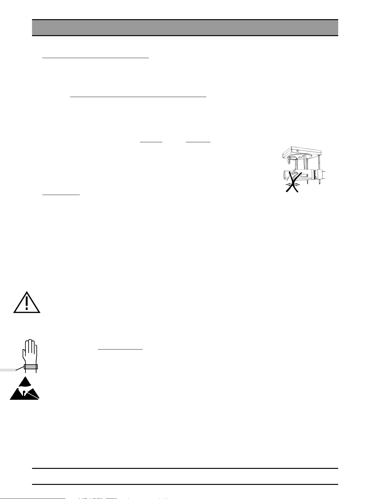
• Do not move the secondary diaphragm by hand or subject it to any stress when
removing from the package.
• Measurements
Before connecting a measuring instrument, always switch the unit OFF.
Select the required current/voltage type and set the measuring range according to the expected value.
Carry out continuity tests only with the unit switched off.
If the release of several exposures with radiation is required for checking the measuring results, you must observe the
specified cool-down intervals. This is ensured by the automatic exposure blockage (see Operating Instructions).
The pulse/interval ratio is 1:10, which means a 10 second pause has to follow after 1 second of radiation. This pulse/interval ratio is automatically guaranteed by the automatic exposure blockage.
However, preferable for the X-ray tube is a pulse/pause ratio of 1:20.
to insert all screws.
!
Adhere to the radiation protection guidelines before generating radiation.
Test runs initiated by pressing the T key on the Multitimer followed by actuation of the exposure release button are executed without radiation, i.e. the kV/mA displays remain blank. l
• Replacing parts
Always turn the unit OFF before replacing any parts.
When parts located close to the line transformer are to be replaced, switch off the power at the distributor box for the onsite electrical system for safety reasons
To protect electrostatic sensitive devices (ESD) on boards, always
wear the wrist band found inside the unit.
The unit must be checked and newly adjusted following the replacement of the DX1 electronics,
the X-ray tube assembly or a diaphragm.
The article numbers for ordering spare parts can be found in the spare parts list, order no. 41 63 841.
The figures in the spare parts list offer valuable assistance when replacing spare parts.
.
1 - 4 D 3297.077.01.10.02 04.2007
54 53 571 D 3297
Page 15
1.2 List of software versions
1.2 List of software versions
IMPORTANT:
No other combinations of software are allowed
since these could result in undefined faults.
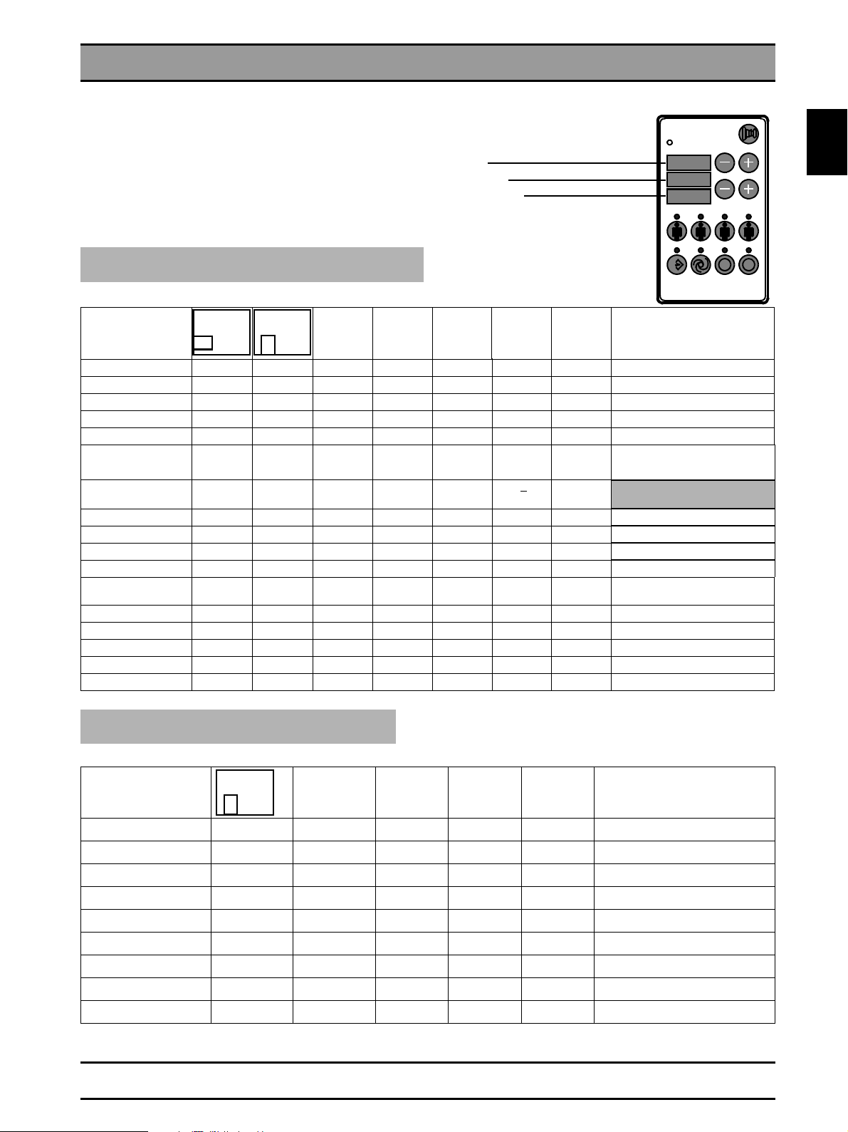
ORTHOPHOS Plus DS / Plus DS Ceph
Multitimer
Versions no. memory card
Software Multitimer D4
Software board DX1
0 2 3
kV
mA
X-RAY
0 6
I 4
T
Unit identification e.g. 10
Overall software
Version 02.1 013 06 18 2.2 1.0
Version 02.2 013 06 20 2.2
Version 02.3 10.96 013 06 21 2.2 2.0
Version 02.4 12.96 013 06 22 2.2
Version 02.4 02.97 013 06 22 2.21 2.1
Version 02.5 06.97 014 06 23 2.21
Version 02.6 01.98 014 06 25 3.2 < to
Version 02.7 06.98 20 06 26 3.2/4.2
Version 02.8 01.99 20 06 27 3.2/4.2 Reduced kV/mA steps
Version 03.10 08.99 20 06 30.10 4.2
Version 04.10 09.99 20 06 31.10 4.2/5.2 kV/mA steps adjustable
Version 05.10 11.00 20 06 35.10 5.28/5.3/
Version 06.10 04.02 21 06 36.10 5.52/5.54 Correcting error E4 04/E3 48
Version 01.12 07.01 20 06 10.12 5.5 Supports TSA digital
Version 02.12 02.02 20 06 10.12 5.52 USB-Box
Version 03.12 05.02 21 06 11.12 5.52/5.54 Correcting error E4 04/E3 48
Version 03.12 08.02 21 06 36.10 11.12 5.55
DX1
EEPROM
M M
J115
DX1
EEPROM
J115
D4
EEPROM
J4
Memory
Card
Memory
Card
TSA
SIDEXIS Service-
disk
5.55
5.5
3.2 General update has been sent
Pulse/interval blockage 1:10.
LEDs of ORTHOPHOS symbol are
active during service routines.
to all customers.
Supports XAB-OP
Remarks
1.2
R
ORTHOPHOS 5 / Plus / Plus Ceph
Unit identification e.g. 50
Overall software DX1
Ver si on
01.50
Ver si on
01.51
Ver si on
01.52
Ver si on
02.50
Ver si on
02.51
Ver si on
02.52
03.52
Ver si on
Ver si on
04.50
Ver si on
05.52
EEPROM
M
J115
020 06 011.50
020 06 010.51
020 06 010.52
020 06 012.50
020 06 011.51
020 06 012.52
020 06 013.52
021 06 13.50
021 06 014.52
D4
EEPROM J4
Memory
Card
ORTH. Plus
Memory
Card
ORTH.
ATTENTION! Invalid data are indicated if DX1 switch S101 is in the wrong position.
54 53 571 D 3297
D 3297.077.01.10.02 04.2007
Memory
Card
ORTH. TS
Remarks
1 - 5
Page 16
1.3 Major Assemblies and Components
1.3 Major Assemblies and Components
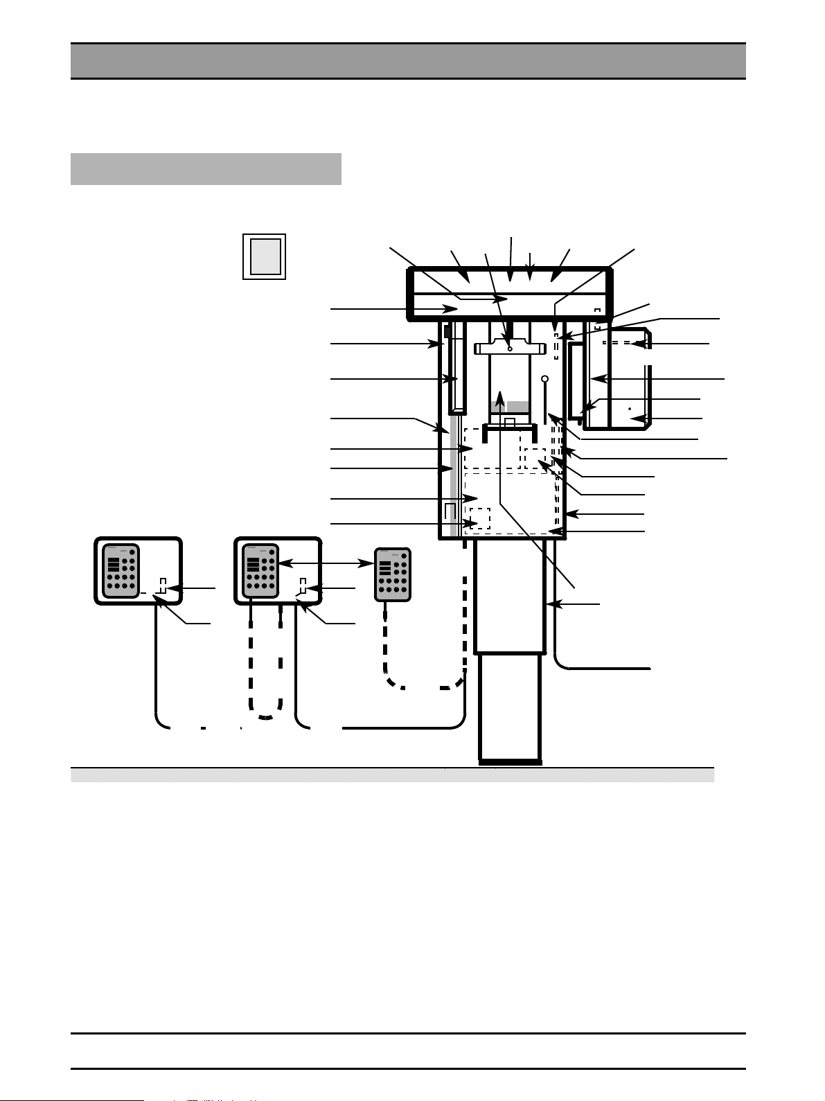
ORTHOPHOS Plus DS
Main switch
ON
OFF
S1
I
O
Terminal strip K1,
transformer T1 and board
DX31 behind door and cover.
Remote control . . .
K10
L11
K11
. . . without
coiled cable
. . . with
coiled cable
L9
L8
K2
Rear
panel
L9
M6
V2
RHB
DX31
BE, EDC
DX7, A
DX32
F1,
DX1
DX20, M
D4
K10
L12
Control cable of
remote control
L8
M3
V4
R1 V5, V7
K2
M1
M2
V3
M5
V6, V8
K3
DX5
D6
X-ray tube assembly
S3, S4
S2
H1
EGB
XAB OP / DEB
XAB D
DX71
DX91
S
HV
H1, H2 light localizer
Serial no.
hardware
software
L30/L31/L32/LAN
DX71 and DX20 omitted from serial no.
1400 (ORTHOPHOS Plus DS),
50400 (ORTHOPHOS Plus DS Ceph)
DEB discontinued as of serial no.
2000 (ORTHOPHOS Plus DS),
52000 (ORTHOPHOS Plus DS Ceph)
and replaced by XAB OP, XAB D
A = Membrane keypad
BE = Image receptor
DEB, EDC,
RHB, D,
DX, XAB= PC boards
M = Memory card
H1 = X-ray tube assembly
F1, F2 = Main fuses
M1 = Motor for rotation
M2/3 = Actuators
M5 = Motor for height adjustment
M6 = Motor for forehead support movement
H1/H2 = Light localizer
K = Connector/terminal strips on/in the unit
L = Leads/cables
R1 = Potentiometer for forehead support
S = Switch
S
X = Connectors on boards
V2 - V8 = Light barriers
V2 = Forehead support, zero position
V3 = Start position for actuator M2
V4 = Start position for actuator M3
V5 = Start position for rotation
V6 = Height adjustment pulses
V7 = Rotation ring in Ceph position
V8 = Ceph synchronization pulses
= Correction switch for height adjustment
HV
54 53 571 D 3297
1 - 6 D 3297.077.01.10.02 04.2007
Page 17
1.3 Major Assemblies and Components
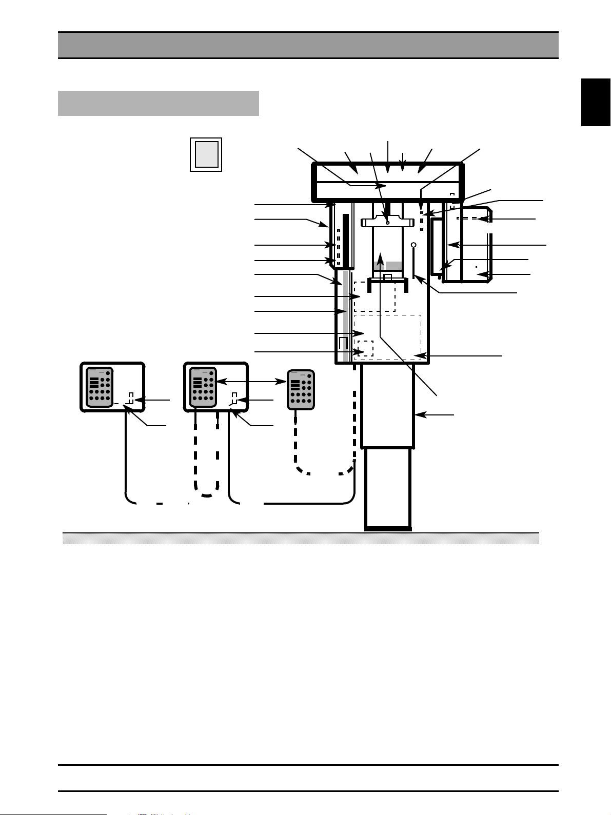
ORTHOPHOS PLUS
Main switch
ON
OFF
S1
O
I
Rear
panel
Terminal strip K1,
transformer T1 and board
DX31 behind door and cover.
Remote control . . .
K10
M6
V2
V11, V12
DX31
DX8, M4,
V10
DX7, A
DX32
F1,
DX1
M
D4
K10
M3
V4
R1 V5, V7
K2
M1
M2
V3
M5
V6, V8
X-ray tube assy
EGB
S
HV
H1, H2 Light localizer
K3
1.3
DX5
D6
S3, S4
S2
H1
L11
K11
. . . without
coiled cable
A = Membrane keypad
D, DX = PC boards
M = Memory card
H1 = X-ray tube assembly
F1, F2 = Main fuses
M1 = Motor for rotation
M2/3 = Actuators
M4 = Motor for cassette movement
M5 = Motor for height adjustment
M6 = Motor for forehead support movement
H1/H2 = light localizer
K = Connector/terminal strip on/in the unit
L = Leads/cables
. . . with
coiled cable
L9
K2
L8
L9
L12
Control cable of
remote control
Serial no.
hardware
software
L8
R1 = Potentiometer for forehead support
S = Switch
S
X = Connectors on boards
V2 - V8 = Light barriers
V2 = Forehead support, zero position
V3 = Start position for actuator M2
V4 = Start position for actuator M3
V5 = Start position for rotation
V6 = Height adjustment pulses
V7 = Rotation ring in Ceph position
V8 = Ceph synchronization pulses
= Correction switch for height adjustment
HV
54 53 571 D 3297
D 3297.077.01.10.02 04.2007
1 - 7
Page 18
1.3 Major Assemblies and Components
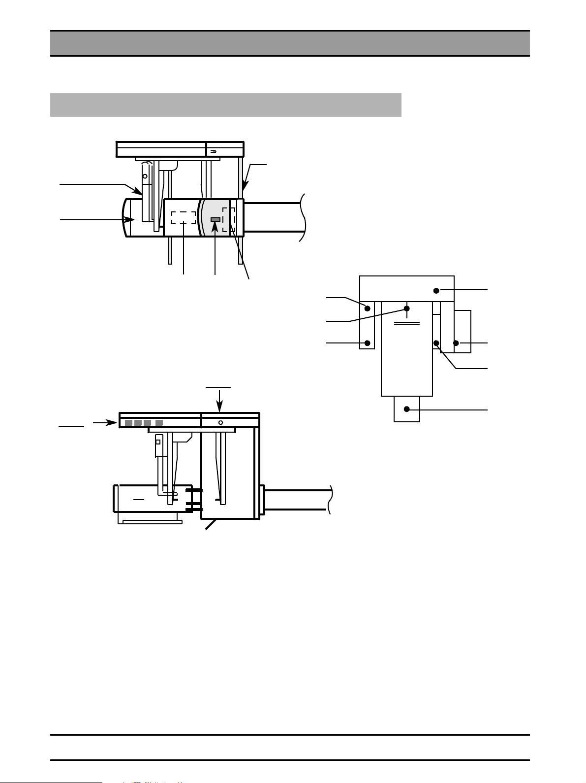
ORTHOPHOS Plus Ceph and ORTHOPHOS Plus DS Ceph
ORTHOPHOS Plus DS Ceph
Serial number
DAB
BE, EDC
M7
H3
D10
D11
ORTHOPHOS Plus Ceph
DAB = Image receptor supply board, Ceph
BE = Image receptor
EDC = Image receptor electronics
M7 = Motor for Cephalometer with brake
and encoder
M8 = Motor for patient diaphragm
H3 = Light localizer
D10 = Control board
D11 = Control panel
M8
V7
V4
V6
LED indication of help messages
V1 = Cool-down interval
V2 = X-ray tube assembly position Pan / Ceph
V3 = Setting of diaphragm
V4 = Position of forehead support
V5 = Height adjustment
V6 = Image receptor plug-in position /
exposed film inserted
V7 = Readiness for exposure SIDEXIS /
cassette holder not in position
V2
V1
V3
V5
1 - 8 D 3297.077.01.10.02 04.2007
54 53 571 D 3297
Page 19
1.4 Removing Panels
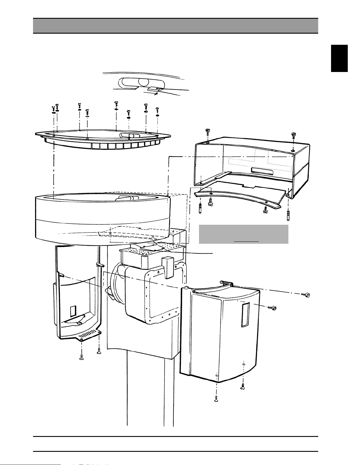
1.4 Removing Panels
X-ray tube assembly, rotation ring
1.4
Push this cuff aside before lifting off
the panel!
Align lower panel to the rotation ring
(gap of equal width).
Secure with 2 M4 screws from below.
Always tighten the four
mounting screws!
54 53 571 D 3297
D 3297.077.01.10.02 04.2007
1 - 9
Page 20
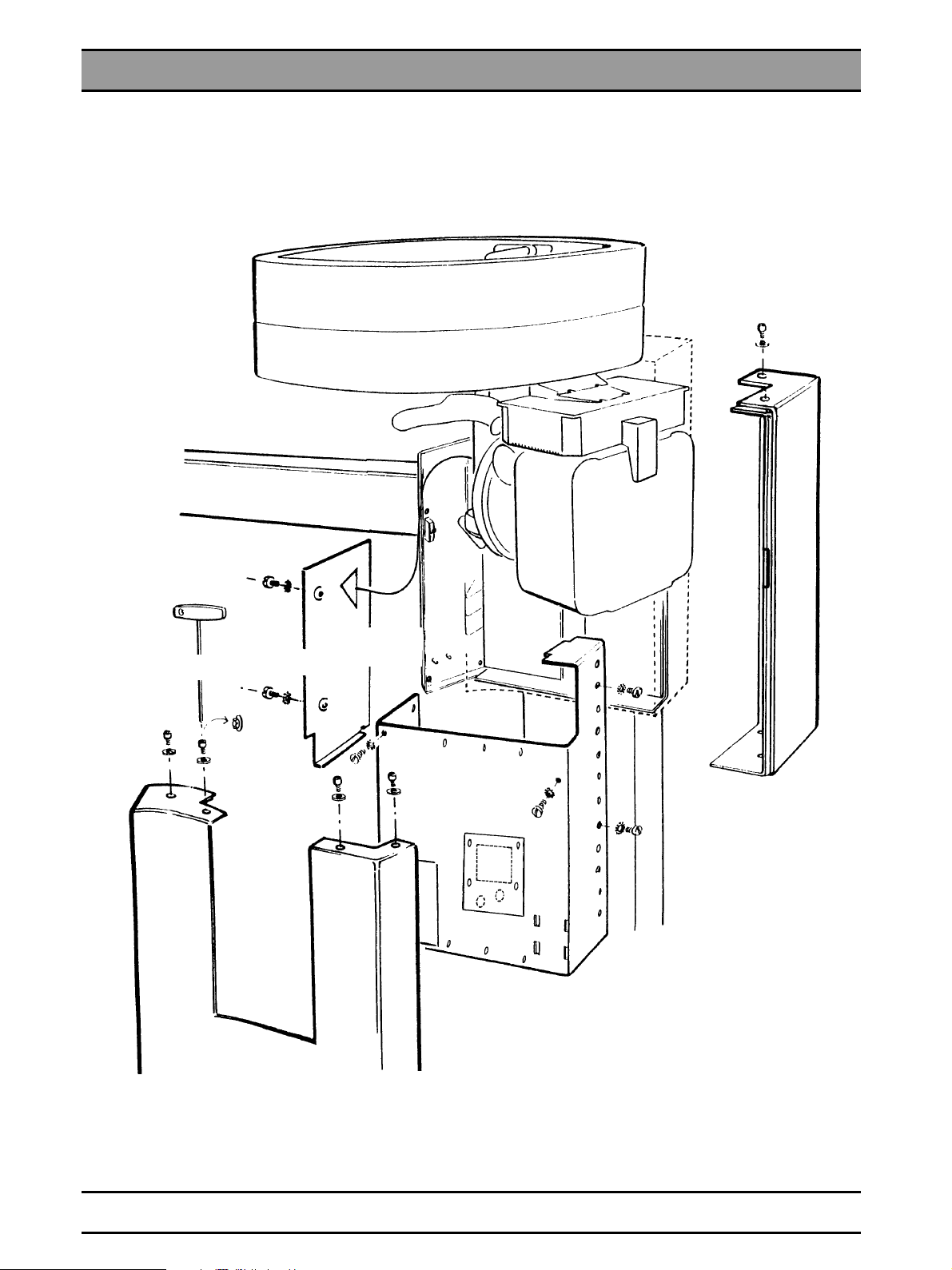
1.4 Removing Panels
Unit carriage
Special screwdriver
Transformer
cover
Spare fuses
5 – 29 screws
This cover can only be removed after the panels behind the
rotation ring have been taken off.
NOTE: For ORTHOPHOS Plus DS TSA, take TSA imagereceptor out of side
holder before removing the panels.
54 53 571 D 3297
1 - 10 D 3297.077.01.10.02 04.2007
Page 21
1.5 Photographs of PC Boards
)
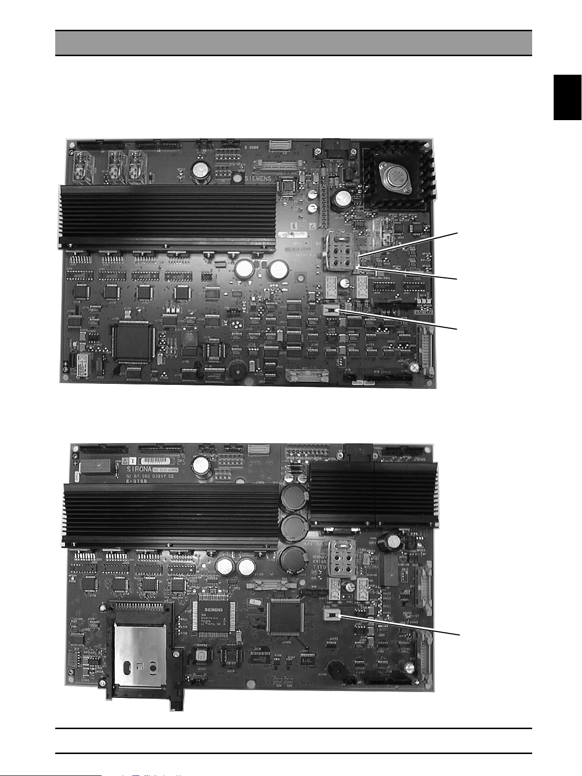
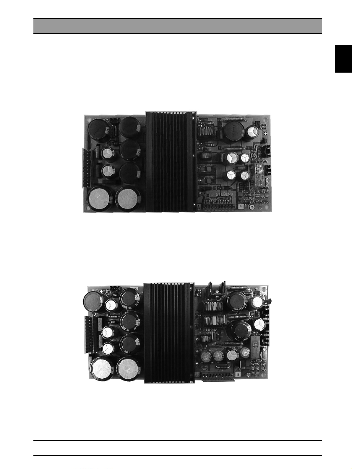
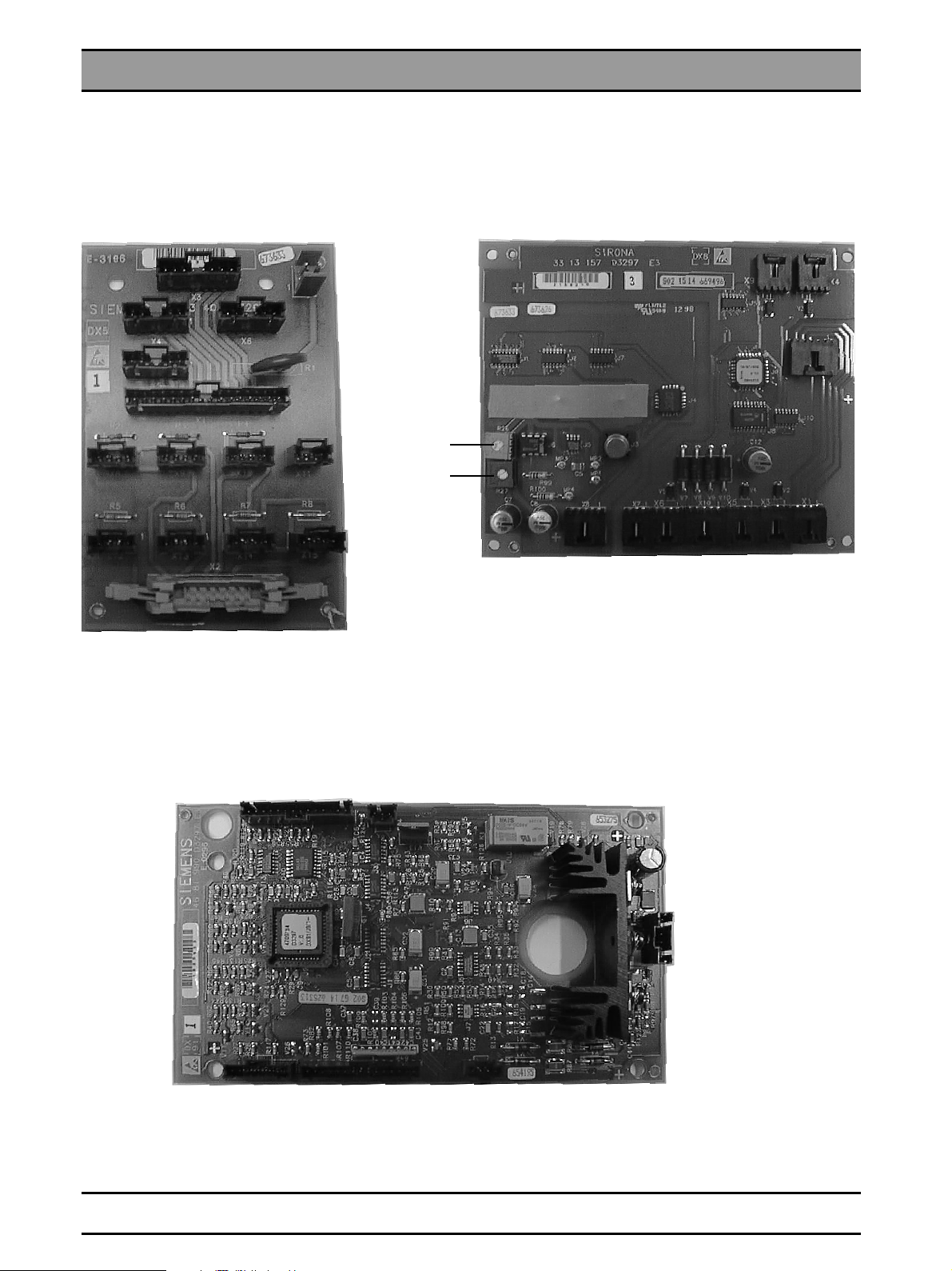
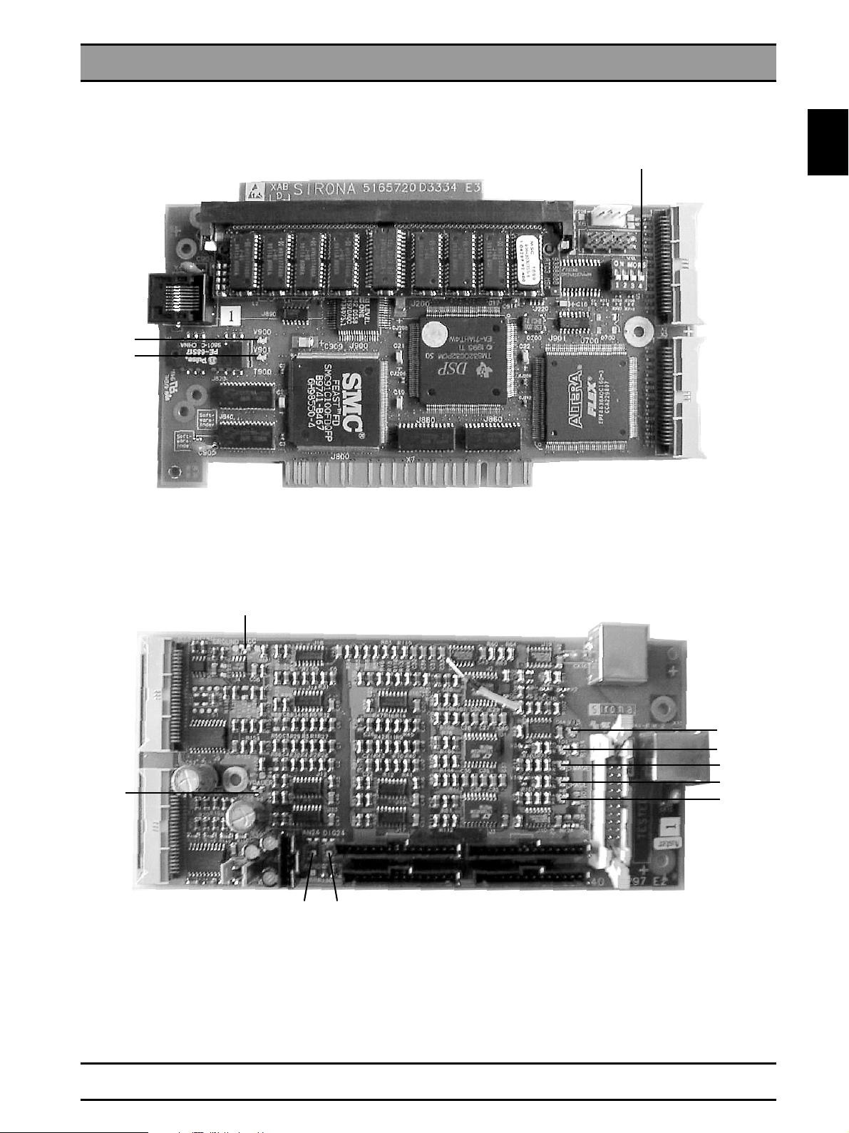
1.5 Photographs of PC Boards
DX1 board
33 13 108
1.5
with Memory Card 256kB
MA setpoint
VH setpoint
Switch S101
Position 2 (at right)
otherwise reading
from memory card
not possible
51 67 080
with Memory Card 256KB or 2MB
Switch S101
Position 2 (at right
otherwise reading
from memory card
not possible
54 53 571 D 3297
D 3297.077.01.10.02 04.2007
1 - 11
Page 22
1.5 Photographs of PC Boards
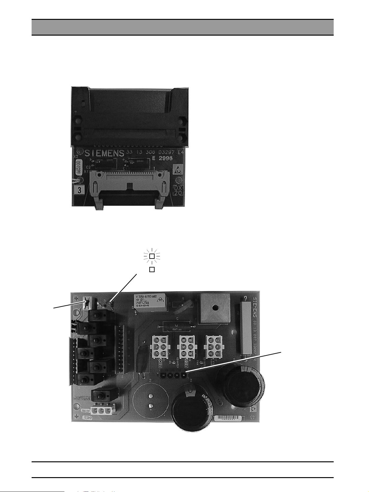
DX20 / DX31 boards
DX20
S.88
Position 2
Demonstrationmode
DX31
V3
Radiation
S.88 Demonstration mode
X2 High voltage
1 - 12 D 3297.077.01.10.02 04.2007
54 53 571 D 3297
Page 23
DX32 board
1.5 Photographs of PC Boards
1.5
DX32 E4
DX32 E5
54 53 571 D 3297
D 3297.077.01.10.02 04.2007
1 - 13
Page 24
1.5 Photographs of PC Boards
DX5 / DX8 / DX91 boards
DX5
DX8
R26
R27
DX91
1 - 14 D 3297.077.01.10.02 04.2007
54 53 571 D 3297
Page 25
RHB board
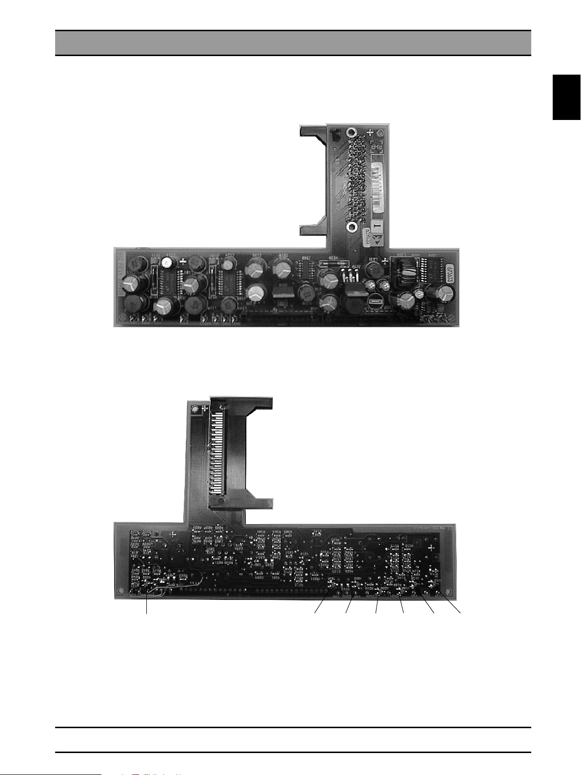
1.5 Photographs of PC Boards
1.5
RHB
D+5V A+5VA-5VA+24VD+24V+18V-18V
54 53 571 D 3297
D 3297.077.01.10.02 04.2007
V200 V100 V112V122V212V232V222
1 - 15
Page 26
1.5 Photographs of PC Boards
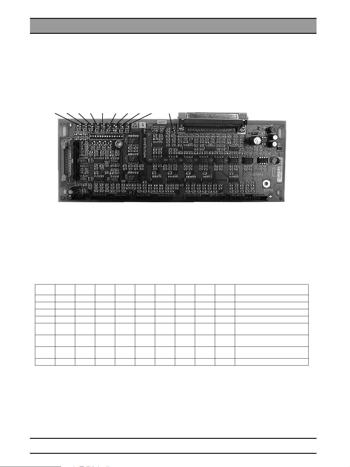
DEB board
DEB
V905 V900 V216V221V910 V670 V350 V232V231
V950
V216 LED, Out clock pulses TDI
V221 LED, radiographic mode
V231 LED, Ceph radiography mode
V232 LED, Panoramic radiography mode
V350 LED, EDC Reset (not inserted)
V670 LED, PC exposure readiness ACTIVE signal
V900 LED, digital supply voltage RHB +24V
V905 LED, analog supply voltage RHB +24V
V910 LED, supply voltage DEB +5V ORTHOPHOS
V950 LED, supply voltage DEB +5V PC (if XOP not correctly configured)
V905 V900 V910 V221 V216 V670 V350 V231 V232 V950 Status
XXXStandby Pan
X X X Standby Ceph
X X X X X Panoramic radiography mode
X X X X X Ceph radiography mode
XXXX X XX
XXXX X X X
XXXXglowsX XX
XXXXglowsX X XCeph radiography mode X-ray
Panoramic radiography mode
Image generation test image
Ceph radiography mode
Image generation test image
Panoramic radiography mode
X-ray
1 - 16 D 3297.077.01.10.02 04.2007
54 53 571 D 3297
Page 27
XAB OP and XAB D boards
1.5 Photographs of PC Boards
XAB D
V900
V901
V900 = RD Transmit, GN Receive
V901 = RD Link (adress recognition), GN 100Mbps (Megabits per sec)
Coding switch
1.5
XAB OP
V10
V9
V12 V11
V5 LED, TDI distance pulses
V6 LED, IMAGE radiographic mode
V7 LED, radiographic mode Pan/Ceph
V8 LED, Panorama-Aufnahmemodus
V9 LED, V continuous
V10 LED, VCC +5V
V11 LED, Digital supply voltage +24V
V12 LED, Analog supply voltage +24V
V13 LED, PC exposure readinesst ACTIVE signal
V13
V5
V6
V7
V8
54 53 571 D 3297
D 3297.077.01.10.02 04.2007
1 - 17
Page 28

1.5 Photographs of PC Boards
1 - 18 D 3297.077.01.10.02 04.2007
54 53 571 D 3297
Page 29

2 List of Messages
Page 30

Contents Sirona Dental Systems GmbH
List of Messages
Contents
2.1 List of Help Messages ........................................................................................................ 2 - 3
2.2 List of Error Messages ........................................................................................................ 2 - 4
2.3 List of Service Routines ...................................................................................................... 2 - 9
2.4 List of Error Messages for SIDEXIS ................................................................................. 2 - 10
2 - 2 D 3297.077.01.10.02 04.2007
54 53 571 D 3297
Page 31

2.1 List of Help Messages
If the Ready LED above the R key on the Multitimer flashes when you try
to trigger an exposure, you can call up H3 help messages on the Multitimer:
• Press the X-ray key on the Multitimer.
CAUTION: Take radiation protection measures.
The H3 . message then appears on the kV/mA display.
• Find in the following list the actions required to return the unit
to readiness for exposure.
• Before
carrying out the required action clear the help message
by pressing the R key on the Multitimer.
Help
message
H3 01
Rotation unit not in the start position. V2 Press the Return key R, see page 3 - 11.
Film cassette not inserted or not engaged. V7 Slide loaded film cassette into the cassette tray
Description Required action
H3 02
H3 03
Exposed film cassette not replaced after last
exposure. V6
Cassette holder not in Panorama position. V7 Swivel cassette holder to stop position. For error
H3 04
H3 05
H3 06
Panorama
H3 07
No Panorama diaphragm set with the diaphragm
wheel. V3
Locking button on diaphragm wheel not engaged
(Panorama diaphragm). V3
Forehead support is in an incorrect position for the
selected program. V4
Cassette holder not in Ceph position. V7 Swivel cassette holder to stop position. For error
H3 11
H3 12
H3 16
H3 20
H4 01
H4 03
H4 05
Rotation unit not in start position for cephalometry. V2Drive rotation unit to cephalometry position (press
Ceph function not selected. V3 Select Ceph function by pressing the C key, see
Radiographic data not acknowledged. V7 Acknowledge radiographic data with Return key R.
Image receptor not inserted according to selected
exposure. V7
SIDEXIS not ready for exposure. V6 Make SIDEXIS ready for exposure.
Height adjustment not in the range for Ceph exposures. V5
Patient fixation on Ceph not in the basic position. V5Move Cephalometer without a patient to position
H4 06
until it engages. For error correction follow service
routine S.16, see page 5 - 45.
Remove exposed film from the cassette and insert
a fresh film.
correction follow service routine S.16, see page
5 - 45.
Set diaphragm wheel to diaphragm for the
selected program, see page 3 - 13.
Correctly engage locking button on diaphragm
wheel, see page 3 - 13.
Move forehead support to correct position, see
page 3 - 15.
correction follow service routine S.16, see page
5 - 45.
R key) and lock it, see page 3 - 17.
page 3 - 19.
Insert image receptor according to exposure set.
For error correction follow service routine S.32/
S.33, see page 5 - 77.
See SIDEXIS Service Manual.
Move stand without a patient to a position accept-
able for cephalometry. For error correction follow
service routine S.18, see page 5 - 51.
for cephalometry. If the error occurs repeatedly,
correct by performing service routine S.34.1,
see page 5 - 83.
H4 10
Ceph oder SIDEXIS
H4 20
Image receptor not suitable for exposure set. Replace the image receptor in the plug-in location
Image could not be transferred to SIDEXIS.
according to the programmed acquisition.
Transfer exposure by SiRescue service program
to the PC, see SIDEXIS User Manual.
CAUTION Do not switch off the unit until the help
message goes out.
V7
V4
V6
V2
V1
V3
V5
2.1
The above mentioned actions will eliminate help messages caused by operating errors.
If the help message cannot be eliminated by the above actions, the fault is of another nature. Proceed with
troubleshooting as described on the following pages.
54 53 571 D 3297
D 3297.077.01.10.02 04.2007
2 - 3
Page 32

2.2 List of Error Messages
Error
message
E1 01
E1 02
E2 03
Multitimer
E1 03
E2 01
E2 03
E2 04
E2 10
E2 11
E2 12
E2 13
E2 14
E2 15
E2 16
X-ray tube assembly E2 . . .
E2 18
E2 20
E2 35
E2 40
Description
A key on the Multitimer was pressed during selfadjustment or is defective.
Signal paths to control board D1 are interrupted. Proceed according to section "Correcting error E1
Faulty communication with the unit. Acknowledge the fault by pressing the R key on
Appears upon pressing the exposure button.
Overheated X-ray tube assembly, pulse/pause
ratio not observed.
See LED Orthophos symbol.
Proceed according to section "Correcting error E1
01", see page 3 - 21.
02, see page 3 - 21.
the Multitimer.
Acknowledge the fault by pressing the R key on
the Multitimer. Allow the X-ray tube assembly to
cool down. If the error message reoccurs, proceed
according to section "Correcting error E2 01",
Required action
see page 3 - 23.
See E1 02 see page 3 - 21
Zero power range has been re-initialized. Acknowledge the fault by pressing the R key on
Max. radiation time of the program exceeded. Only possible in service mode; acknowledge the
kV
(tube voltage) exceeded. Proceed according to section "Correcting error E2
max.
mA
(tube current) exceeded. Proceed according to section "Correcting error E2
max.
VH
(filament voltage) exceeded. Proceed according to section "Correcting error E2
max.
Short-circuit of an output stage on D6 with voltage/frequency converter on DX1 deactivated.
VH
continuously present. Proceed according to section "Correcting error E2
max.
kV
cable is interrupted. Proceed according to section "Correcting error E2
actual
Non-localizable fault in obtaining the DC/AC signals.
Occurs upon pressing the exposure button e.g.
with the X-ray room door contact open - exposure
release lead in the Multitimer cable is broken.
Invalid data in the data memory. Erase data in the EEPROM with 'Service Routine
VH setpoint out of tolerance ± 10 %. Proceed according to section "Correcting error E2
the Multitimer. Unfortunately, the freely
programmed values will be lost. and must be
reprogrammed. If not possible: correct the error
with E2 04, see page 3 - 25.
fault by pressing the R key on the Multitimer. Or
Ceph mode is too slow: proceed according to section "Correcting error E2 10", see page 3 - 27.
11", see page 3 - 29.
12", see page 3 - 31.
13", see page 3 - 33.
Proceed according to section "Correcting error E2
14", see page 3 - 35.
15", see page 3 - 37.
16", see page 3 - 39.
Acknowledge the fault by pressing the R key on
the Multitimer. If fault reoccurs, DX1 board is
defective → replace. Perform "Adjusting board
DX1”, see page 4 - 39.
Close X-ray room door. Acknowledge the fault by
pressing the R key on the Multitimer. If the fault
reoccurs, proceed according to section "Correcting error E2 20", see page 3 - 41.
09'. Then press the R key. If the message reoccurs, DX1 board is defective → replace and perform "Adjusting board DX1”, see page 4 - 39.
40", see page 3 - 45.
2 - 4 D 3297.077.01.10.02 04.2007
54 53 571 D 3297
Page 33

2.2 List of Error Messages – Continued
Error
message
E2 41
E2 42
E2 43
E2 44
E2 45
E2 46
E2 47
X-ray tube assembly E2 . . .
E2 48
E3 01
E3 02
E3 03
E3 04
E3 05
E3 06
E3 08
E3 09
Unit E3 . . .
E3 10
E3 11
E3 12
E3 21
E3 22
Description
kV setpoint out of tolerance ± 5 %. Adjust board DX1. If not possible, DX1 board is
defective → replace and adjust, see page 4 - 39.
mA setpoint out of tolerance ± 5 %. Adjust board DX1. If not possible, DX1 board is
defective → replace and adjust, see page 4 - 39.
VH actual value out of tolerance ± 10 %. Adjust board DX1. If not possible, DX1 board is
defective → replace and adjust, see page 4 - 39.
kV actual value out of tolerance ± 10 %. Adjust board DX1. If not possible, DX1 board is
defective → replace and adjust, see page 4 - 39.
mA actual value out of tolerance ± 10 %. Proceed according to section ”Correcting error E2
45", see page 3 - 47.
Error while increasing or decreasing the kV value. Software error or DX1 board defective → replace
and perform "Adjusting board DX1”,
Required action
see page 4 - 39.
Incorrect setpoint value after automatic setpoint
adjustment.
Faulty user offset while increasing the kV value. Acknowledge the fault by pressing the R key. Cau-
Operating element for light barrier V3 of actuator
M2 has not left/reached the tripping position.
Operating element for light barrier V4 of actuator
M3 has not left/reached the tripping position.
Cassette carriage has not left/reached the reference point.
Fault in film motor counter. Acknowledge the fault by pressing the R key. If the
Adjust board DX1. If not possible, DX1 board is
defective → replace and perform "Adjusting board
DX1”, see page 4 - 39. EEPROM defective.
tion: If the offset was changed by the user (possible in the range from -6 to +3) it will be reset to
zero. If the fault reoccurs, the DX1 board is defective → replace and perform "Adjusting board
DX1”, see page 4 - 39.
Proceed according to section "Correcting error E3
01/02", see page 3 - 49.
Proceed according to section "Correcting error "
E3 03/04”, see page 3 - 51.
Proceed according to section "Correcting error E3
05 /06", see page 3 - 53.
fault reoccurs, the DX1 board is defective →
replace and perform "Adjusting board DX1”,
see page 4 - 39.
Pulses for height adjustment are not within the
allowed time.
Count for height adjustment too high/too low for
reference setting.
Key for height adjustment ↑↓ was pressed during
self adjustment or is defective.
Key for anomaly A (control panel A) was pressed
during switch-on procedure or before completion
of unit self-adjustment.
Key for light localizer (control panel A) was
pressed during switch-on procedure or before
completion of unit self-adjustment.
Proceed according to section "Correcting error E3
09/E4 03", see page 3 - 55.
Proceed according to section "Correcting error E3
10/11", see page 3 - 59.
Proceed according to section "Correcting error E3
12", see page 3 - 61.
Acknowledge the fault by pressing the R key on
the Multitimer or the key/lead is defective.
Acknowledge the fault by pressing the R key on
the Multitimer.
2.2
54 53 571 D 3297
D 3297.077.01.10.02 04.2007
2 - 5
Page 34

2.2 List of Error Messages – Continued
Unit E3 . . .
Error
message
E3 23
E3 24
E3 25
E3 26
E3 27
E3 28
E3 29
E3 30
E3 31
E3 32
E3 33
E3 35
E3 36
E3 37
E3 38
E3 39
E3 41
E3 42
E3 43
E3 45
Description
Return key R on control panel A was pressed during the switch-on procedure or before completion
of unit self-adjustment.
"“X-Ray Control” is indicated at switch-on. a) If error message occurs in combination with
Incorrect data for exposure control. Memory card or DX1 defective → replace and per-
Data in EEPROM not compatible with software
version of memory card.
Zero point of forehead support was not exited/
reached.
Software limit switch of forehead support was
reached before zero point.
Counter IC of forehead support not counting correctly.
One of the keys ← → for forehead support adjustment was pressed during switch-on procedure or
before completion of unit self-adjustment.
Start position for rotation was not exited/reached. Proceed according to section "Correcting error E3
Rotation counter not counting correctly. Software error or DX1 board defective → replace
Acknowledge the fault by pressing the R key on
the Multitimer.
E1 02: button was recognized on Multitimer as
actuated - check buttons or replace Multitimer.
b) If error message occurs alone, pull out Multitimer and switch on again. If error message
occurs again: DX1 defective → replace and perform “Adjusting board DX1”, see page 4 - 39. If
error message no longer occurs: replace Multitimer.
form "Adjusting board DX1”, see page 4 - 39.
Check for compatibility of software versions
according to the list, see page 1 - 5. Install the
correct software combination, or the memory card
or DX1 is defective. Adjust unit identification with
Service routine S.17, see page 5 - 49.
Proceed according to section "Correcting error E3
27/28/29", see page 3 - 63.
Acknowledge the fault by pressing the R key on
the Multitimer.
DX1 board defective → replace and perform
"Adjusting board DX1, see page 4 - 39”.
Acknowledge the fault by pressing the R key on
the Multitimer. Key defective?
32/33", see page 3 - 65.
and perform "Adjusting board DX1”,
Required action
see page 4 - 39.
Cassette holder was swivelled from the Pan position during the Pan exposure.
Counter IC of actuators not counting correctly. DX1 board defective → replace and perform
Light barrier for Ceph position rotation indicates
invalid status.
Error with counter for kV increase. DX1 board defective → replace and perform
Rotation has not reached Ceph position. Light barriers V7/V8 maladjusted/defective.
Error with counter for radiation times. DX1 board defective → replace and perform
Diaphragm inserted not recognized. After service routine 09, after replacing DX1 or
Proceed according to section "Correcting error E3
36", see page 3 - 69.
"Adjusting board DX1”, see page 4 - 39.
Proceed according to section "Correcting error E3
39", see page 3 - 73.
"Adjusting board DX1”, see page 4 - 39.
"Adjusting board DX1”, see page 4 - 39.
EEPROM → reprogram the diaphragm. Check
function of diaphragm switch!
2 - 6 D 3297.077.01.10.02 04.2007
54 53 571 D 3297
Page 35

2.2 List of Error Messages – Continued
Error
message
E3 46
E3 47
E3 48
E3 49
E3 50
Unit E3 . . .
E3 51
E3 52
E3 53
E4 01
E4 02
E4 03
E4 04
E4 06
E4 07
E4 08
E4 09
Ceph or SIDEXIS
E4 10
E4 11
E4 12
E4 13
E4 14
Description
Position of cassette holder cannot be determined. Proceed according to section "Correcting error E3
Memory card not inserted. Insert memory card.
Memory card which is plugged in is not valid or is
not always detected.
Watchdog reset performed. Acknowledge the fault by pressing the R key. Fault
46",
If the error message occurs frequently, order conversion kit: Replace memory card and GAL
J1121.
occurs with voltage fluctuations; if reoccurring frequently: DX32 or DX1 board is defective →
replace and perform "Adjusting board DX1”,
Required action
see page 3 - 75.
see page 4 - 39.
This service exposure is not possible in the demonstration mode.
Inaccurate signals indicated by the film drive control.
Unit identification does not match the inserted
memory card.
Switch S101 in left-hand position. Turn switch S101 to right-hand position.
Exposure aborted by SIDEXIS. Proceed according to section "Correcting error E4
Fault indicated by control unit of Ceph motor. Proceed according to section "Correcting error E4
Light barrier for Ceph control not emitting any
pulses.
Motor for secondary diaphragm not moving. Proceed according to section "Correcting error E4
Fault at one of the supply voltages. Proceed according to section "Correcting error E4
Fault in TDI pulse generation. DX1 board defective → replace and perform
Aborted by SIDEXIS during radiation. Proceed according to section "Correcting error E4
Fault at limit switches of Ceph drive. Proceed according to section "Correcting error E4
Communication fault with image acquisition card
XOP (in PC) or XAB OP (in ORTHOPHOS).
Image receptor not ready for exposure. Proceed according to section "Correcting error E4
Image receptor is not logged in. Load contents of image receptor floppy.
Pan image receptor in Ceph plug-in position. Insert Ceph image receptor in Ceph slot.
Ceph holder not moving (Ceph Pot.) Proceed according to section "Correcting error E4
Deactivate demonstration mode. Turn test switch
S1/S88 on DX31 to position 1. V3 on DX31 must
light up. Observe section "Demonstration mode
cannot be switched ON/OFF", see page 3 - 9.
Proceed according to section "Correcting error E3
51", see page 3 - 77.
Always perform service routine S.17 when replacing DX1 or changing from ORTHOPOS 5 to Plus
or TS or DS, see page 5 - 49.
01", see page 3 - 79.
02", see page 3 - 83.
Proceed according to section "Correcting error E4
03/E3 09", see page 3 - 87.
04", see page 3 - 89.
06", see page 3 - 93.
"Adjusting board DX1”, see page 4 - 39.
08", see page 3 - 97. In service program →
make SIDEXIS ready for exposure;
factory service 2.
09", see page 3 - 105.
With image acquisition card XOP: check cable
L30/L31 and DEB board.
With XAB OP: XAB OP does not respond or has
crashed. Switch unit off and on again.
Or not in correct service mode in SIDEXIS.
11", see page 3 - 107.
14", see page 3 - 115.
2.2
54 53 571 D 3297
D 3297.077.01.10.02 04.2007
2 - 7
Page 36

2.2 List of Error Messages – Continued
Error
message
E4 15
E4 16
E4 17
E4 18
E4 19
Ceph or SIDEXIS
E4 21
E4 30
E4 31
–
–
–
– – –
–
–
–
– – –
Description
Ceph holder has not moved to limit switch. Proceed according to section "Correcting error E4
Active signal present when switching ON. Check SIDEXIS readiness for exposure.
Software versions of DX1 and XAB OP boards are
not compatible.
Image receptor could not be addressed prior to
exposure.
A software download of XAB OP is performed (no
acknowledgement of error message possible).
The XAB OP is in the initialization phase (Boot
Service) (proceed as described in SIDEXIS service manual; SIXABCON description). The XAB
OP has no valid IP address.
The image receptor has an initialization error or
incorrect setting data.
Error on sensor adjustment of TSA image receptor.
Indication at Multitimer.
Communication between control board DX1 and
Multitimer / board D4 is faulty.
Indication for height adjustment:
Height adjustment data not present.
Indication at Multitimer
and
indication for height adjustment
simultaneously.
15", see page 3 - 119.
With XOP board: Check line path from XOP board
in PC to DEB/DX1 board.
With XAB OP board: Check line path from DX1
board to XAB OP board.
Proceed according to section "Correcting error E4
16", see page 3 - 121.
Establish a valid software combination by replacing the memory card; load a new XAB-OP software version (see SIDEXIS service manual);
SIXABCON description.
Proceed according to section "Correcting error E4
11", see page 3 - 107.
Wait until the 4 LEDs above the patient symbols
start flashing; then switch the unit off. Software
download is completed.
After a valid IP address has been assigned by
SIXABCON the error message can be acknowledged on the unit (R key).
Read out error memory of EDC, replace image
receptor if necessary. Check installation of
SIDEXIS.
Perform service routine S.32, test step 06.
Check mains voltage and terminal strip K1. Check
Multitimer cable. Measure supply voltage at DX1
X1; if OK, DX1 board is defective; if not, DX31,
DX32 or cable is defective.
Press key ↑ or ↓:
error message E3 10 or E3 11 .
↑ E3 10 : unit above the correction switch.
Press R key on Multitimer. Press ↓ key until the
height indication appears.
↓ E3 11 : unit below the correction switch.
Press R key on Multitimer. Press key ↑ until the
height is indicated.
DX1 board is defective → replace and perform
"Adjusting board DX1”, see page 4 - 39.
Required action
2 - 8 D 3297.077.01.10.02 04.2007
54 53 571 D 3297
Page 37

2.3 List of Service Routines
Service
routine
S.01
S.02
S.03
S.04
S.05
S.06
S.07
S.09
S.11
S.13
S.14
S.15
S.16
S.17
S.18
S.19
S.20
S.21
S.24
S.25
S.26
S.30/31
S.32
S.33
S.34
S.35
S.36
S.37
S.88
Description
Radiation without rotation All adjustments of X-ray tube assembly, e.g. accep-
Radiation without rotation for Ceph See S.01.
Adjustment of kV setpoint, mA setpoint and VH setpoint
Test of actual values kV, mA, VH. After replacing DX1 or X-ray tube assembly.
Heating adjustment After replacing DX1 or X-ray tube assembly.
Reading/deleting the radiation counter After replacing the X-ray tube assembly or in war-
Deleting the error memory After replacing the X-ray tube assembly.
Erasing EEPROM on DX1 (deletes all data) In case of software problems (all software adjust-
Adjusting the kV increase to customer’s request Too much kV increase in the spine region.
Hardware service Problems with DX1 board.
Rotation functions Mechanical malfunctions of rotation, and test of the
Check of actuators Mechanical malfunctions, layer correction, light bar-
Check of film holder Film holder problems.
Unit identification Changing the unit identification.
Height adjustment Checking freedom of movement, adjustment after
Forehead support motor See S.15 and removal of forehead support.
Jaw width Adjusting DX1, functional test of potentiometer for
Diaphragm service Adjusting DX1, fitting a diaphragm.
Software update of EEPROM on DX1 Replacing the EEPROM J115 up to software version
Check and adjustment of film-screen combination Changing the film-screen combination.
Check of automatic exposure system (AES) Adjustment of DX8 for stability testing.
Diaphragm service, Pan/Ceph
(omitted as of memory card V35.1 remote selection
still possible only via SIDEXIS).
Image receptor test, Pan For checking the image receptor.
Image receptor test, Ceph For checking the image receptor.
Ceph arm service Ceph arm problems.
PC service Problems with readiness for exposure.
Acceptance testing, dose measurement Dose measurement.
XAB OP service Read out and delete IP addresses
Demonstration mode Selected with switch S1 on DX31. Switches the unit
tance testing, functional test, head adjustment, diaphragm adjustment.
After replacing the DX1 board, or malfunction of the
X-ray tube assembly.
ranty cases
ments are deleted and must be reprogrammed).
light barriers.
rier adjustment.
replacing gas-operated spring, adjustment of Ceph
movement, test of correction switch and of light barrier pulses.
forehead support.
04.50 / 05.52
Diaphragm adjustment, selected by SIDEXIS.
to demonstration mode (no radiation).
When required
2.3
54 53 571 D 3297
D 3297.077.01.10.02 04.2007
2 - 9
Page 38

2.4 List of Error Messages for SIDEXIS
The following descriptions should always be seen in relation to the ORTHOPHOS Plus DS unit.
With error message E4 01, ORTHOPHOS Plus DS is generally functional and the SIDEXIS messages must be observed.
With other error messages on ORTHOPHOS Plus DS, the SIDEXIS messages indicate secondary faults.
OP: ORTHOPHOS Plus DS
XOP/XAB: Image acquisition card for Panorama X-rays
EDC: Image receptor electronics on ORTHOPHOS Plus DS
Error
message
up to
SIDEXIS 5.2x
Multitimer
Break 1
Multitimer
Break 2
OP
Break 1
OP
Break 2
EDC
Break XXX
XOP
Break 1/2/3
**
XOP
Break 10 **
XOP
Break 30
XOP
Break 40
XOP
Break 50 **
XOP
Break
60/70
Error
message
from
SIDEXIS 5.3
Multitimer
Break
0xA001
Multitimer
Break
0xA002
OP Break
0xB001
OP Break
0xB002
EDC Break
0xCxxx
XAB OP
Break
0xD001/002/
003 **
XAB OP
Break
0xD010 **
XAB OP
Break
0xD030
XAB OP
Break
0xD040
XAB OP
Break
0xD050 **
XAB OP
Break
0xD060/070
Description
Interruption caused by releasing the X-ray
button on the Multitimer during radiation.
Interruption caused by releasing the X-ray
button on the Multitimer between two partial exposures.
Interruption by OP. Check error message on Multitimer.
Interruption by OP. Check error message on Multitimer.
Voltage problem/failure at image receptor,
see Appendix A.
Timeout on the XOP/XAB, no defined functional call from OP within a preset time.
(only for ORTHOPHOS Plus DS Ceph)
Incorrect communication between XOP/
XAB and image receptor.
OP pulses are more than intended for the
exposure.
Image acquisition card holds insufficient
storage space for the intended exposure.
Image acquisition card receives no image
information.
ORTHOPHOS emits incorrect exposure ID. Check the software versions of OP and
The displayed number XXX is an indication
of several error numbers, see Appendix A.
Check for mechanical obstruction of the
OP movement.
Check the software version of OP and
SIDEXIS for compatibility.
Remove the image receptor from its holder
and reinsert it firmly.
Check signal path with XOP:
XOP – cable connection – OP – image
receptor.
Check signal path with XAB:
XAB – image receptor.
Check the voltages at the image receptor.
Check the software versions of OP and
SIDEXIS for compatibility. Check whether
OP is "hung up".
Check the software versions of OP and
SIDEXIS for compatibility.
Check the memory configuration of XOP/
XAB.
Remove EDC from its holder and reinsert it
firmly. Check the signal path:
Check signal path with XOP:
XOP – cable connection – OP – image
receptor.
Check signal path with XAB:
XAB – image receptor.
Check the voltages at the image receptor.
SIDEXIS for compatibility.
Check the error message displayed by the
OP. (data or address bus error?)
Required action
** see Correcting error of message E4 08 and E4 01
54 53 571 D 3297
2 - 10 D 3297.077.01.10.02 04.2007
Page 39

The error message indicates a combination of several fault causes:
e.g. display on SIDEXIS 3 ¦ C
HEX 3 C
2.4 EDC Break Annex A
Valence
8
3
2
4
2
2
2
1
2
1
0
2
8
3
2
4
2
2
2
1
2
1
0
2
Bit76543210
Error
EDC
RESET
EDC
VSP
EDC
VSN
EDC
VDD
EDC
VAN
EDC
VAP
001 1 1 100
These voltages are not present
Bit = 0 Ok, fault has not occurred
Bit = 1 Error, fault has occurred, signal is missing
Bit number Error
0
1
2
3
4
5
EDC VAP ERROR V212 0x01 Voltage VAP +18 V not present/too low
EDC VAN ERROR V232 0x02 Voltage VAN – 18 V not present/too low
EDC VDD ERROR ------- 0x04 Voltage VDD not present/too low
EDC VSN ERROR V122 0x08 Voltage VSN – 5 V not present/too low
EDC VSP ERROR V112 0x10 Voltage VSP +5 V not present/too low
EDC RESET ERROR V222 0x20 Voltage VCC +5 V not present/too low
6
7
LED
RHB
Meaning
or digital section is in reset state
0x40 Internal message
0x80 Internal message
2.4
54 53 571 D 3297
D 3297.077.01.10.02 04.2007
2 - 11
Page 40

2.1
2 - 12 D 3297.077.01.10.02 04.2007
54 53 571 D 3297
Page 41

3 Troubleshooting
Page 42

Contents Sirona Dental Systems GmbH
Troubleshooting
Contents
3.1 Unit cannot be switched on ............................................................................................... 3 - 7
3.2 Demonstration mode cannot be turned ON/OFF ............................................................... 3 - 9
3.3 Correcting error of help message H3 01. ....................................................................... 3 - 11
3.4 Correcting errors of help messages H3 05 and H3 06. ................................................... 3 - 13
3.5 Correcting error of help message H3 07. ........................................................................ 3 - 15
3.6 Correcting error of help message H3 12. ........................................................................ 3 - 17
3.7 Correcting error of help message H3 16. ........................................................................ 3 - 19
3.8 Correcting error of messages E1 01, E1 02, E2 03: Signal paths to
control board DX1 are interrupted. .................................................................................. 3 - 21
3.9 Correcting error of message E2 01: X-ray tube assembly overheated. ........................... 3 - 23
3.10 Correcting error of message E2 04: Zero power range has been re-initialized. .............. 3 - 25
3.11 Correcting error of message E2 10: Max. radiation time of the program
is exceeded. .................................................................................................................... 3 - 27
3.12 Correcting error of message E2 11: Anode voltage too high. .......................................... 3 - 29
3.13 Correcting error of message E2 12: Anode current too high. .......................................... 3 - 31
3.14 Correcting error of message E2 13: Filament voltage too high. ...................................... 3 - 33
3.15 Correcting error of message E2 14: Short-circuit in bridge ............................................ 3 - 35
3 - 2 D 3297.077.01.10.02 04.2007
54 53 571 D 3297
Page 43

Sirona Dental Systems GmbH Contents
3.16 Correcting error of message E2 15: VH
3.17 Correcting error of message E2 16: kV
continuously present. .................................. 3 - 37
max
ACTUAL
– Cable is interrupted. ............................ 3 - 39
3.18 Correcting error of message E2 20: Interrupted exposure lead in Multitimer cable. ....... 3 - 41
3.19 Correcting error of message E2 40: VH setpoint out of tolerance. .................................. 3 - 45
3.20 Correcting error of message E2 45: mA setpoint out of tolerance. .................................. 3 - 47
3.21 Correcting error of messages E3 01, E3 02: Actuator M2 has not
left/reached the tripping position. .................................................................................... 3 - 49
3.22 Correcting error of messages E3 03, E3 04: Actuator M3 has not
left/reached the tripping position. .................................................................................... 3 - 51
3.23 Correcting error of messages E3 05, E3 06: Cassette carriage has not
left/reached the reference point. ...................................................................................... 3 - 53
3.24 Correcting error of message E3 09: Pulses for height adjustment are not
within allowed time. ......................................................................................................... 3 - 55
3.25 Correcting error of messages E3 10, E3 11: Count for height adjustment too
high/too low for reference setting. .................................................................................... 3 - 59
3.26 Correcting error of message E3 12: Key for height adjustment pressed
during unit self-adjustment. ............................................................................................. 3 - 61
3.27 Correcting error of messages E3 27, E3 28: Zero point of forehead support
was not exited/reached. ................................................................................................... 3 - 63
3.28 Correcting error of messages E3 32, E3 33: Start position for rotation
was not exited/reached. ................................................................................................... 3 - 65
3.29 Correcting error of message E3 36: Cassette holder was swivelled from the
Pan position during Pan exposure. .................................................................................. 3 - 69
3.30 Correcting error of message E3 39: Light barrier for Ceph position rotation
indicates invalid status ..................................................................................................... 3 - 73
3.31 Correcting error of message E3 46: Position of cassette holder
cannot be determined. ..................................................................................................... 3 - 75
3.32 Correcting error of message E3 51: Faulty signals output by the film drive control. ....... 3 - 77
3.33 Correcting error of message E4 01: Exposure aborted by SIDEXIS (with XOP) ............. 3 - 79
3.34 Correcting error of message E4 01: Exposure aborted by SIDEXIS (with XAB) ............. 3 - 81
3.35 Correcting error of message E4 02: Fault indicated by control unit of Ceph motor. ........ 3 - 83
3.36 Correcting error of message E4 03: Light barrier for Ceph control not
emitting any pulses. ......................................................................................................... 3 - 87
3.37 Correcting error of message E4 04: Motor M8 for secondary
diaphragm not moving. .................................................................................................... 3 - 89
3.38 Correcting error of message E4 06: Fault at one of the supply voltages (with XOP) ...... 3 - 93
3.39 Correcting error of message E4 06: Fault at one of the supply voltages (with XAB) ....... 3 - 95
3.40 Correcting error of message E4 08: Aborted by SIDEXIS during radiation
(with XOP) ....................................................................................................................... 3 - 97
3.41 Correcting error of message E4 08: Aborted by SIDEXIS during radiation
(with XAB) ...................................................................................................................... 3 - 101
3.42 Correcting error of message E4 09: Faulty signal from limit switches of
Ceph drive. .................................................................................................................... 3 - 105
3.43 Correcting error of message E4 11: Image receptor not ready for exposure
(with XOP) ..................................................................................................................... 3 - 107
54 53 571 D 3297
D 3297.077.01.10.02 04.2007
3 - 3
Page 44

Contents Sirona Dental Systems GmbH
3.44 Correcting error of message E4 11: Image receptor not ready for exposure
(with XAB) ...................................................................................................................... 3 - 111
3.45 Correcting error of message E4 14: Ceph holder not moving. ...................................... 3 - 115
3.46 Correcting error of message E4 15: Ceph holder has not moved to the
upper/lower limit switch. ................................................................................................. 3 - 119
3.47 Correcting error of message E4 16: Active signal present when switching ON
(with XOP) ..................................................................................................................... 3 - 121
3.48 Correcting error of message E4 16: Active signal present when switching ON
(with XAB) ...................................................................................................................... 3 - 123
3 - 4 D 3297.077.01.10.02 04.2007
54 53 571 D 3297
Page 45

Personal notes
54 53 571 D 3297
D 3297.077.01.10.02 04.2007
3 - 5
Page 46

3 - 6
Remote control
ON
OFF
DX31
I
O
DX32
F1, F2
DX1
Netz
Mains
Secteur
Red
S1
I-Automat 1,5A
1
L1
1
1
1
L2
680μH
V2
R1
PTC 14
K1
1
X10
F2
2
I-Automat 3,0A
F4
2
I-Automat 1,5A
F6
2
I-Automat 1,5A
RD +370V
X2.1
X2.2
BU 0V
X2.3
X2.4
L2
YE
GN
BN
WH
L1
WH
BN
GN
OG/PK
GY
YE
BU
RD
BK
VT
WHBK/WHPK
WHBN/WHBU
1
2
1
2
∼28V
P2 0V
∼28V
P4 0V
∼17V
P6 0V
∼17V
P8 0V
∼28V
P10 0V
∼13,5V
0V
+9,5V X3.4
R3
1K8
V3
RD
X4.1
X4.2
X4.4
X4.6
X4.8
X4.10
X4.11
X4.12
X3.1
X3.2
X3.3
X4.3
X4.5
X4.7
X4.9
V1.2
S.88
S1A
S1B
X9
1
1
1
DX32
X2.4 15 0V
X2.3
X2.2
X2.1 +9,5V
V10
+24V
RD
V12
+15V
RD
V14
+16V
RD
V40
+38V
RD
V54
RD
X1.1
∼28V
X1.2
0V
X1.3
∼28V
X1.4
0V
X1.5
∼17V
X1.6
0V
X1.7
∼17V
X1.8
0V
X1.9
∼28V
X1.10
0V
X1.11
∼13,5V
X1.12
0V
33 13 256
V11
+9,5V
RD
V13
–15V
RD
V31
+30V
RD
V52
RD
BR1
9,5V
X1
0
3 2 1
GND30V X7.1
+30V X7.2
GND24V X7.3
+24V X7.4
GND9,5V X7.5
+9,5V X7.6
V56
RD
K1
+30V X5.2
+24V X5.4
X3.10
V53
RD
+5V X6.2
0V X5.1
0V X5.3
X3.1
X3.2
X3.3
X3.4
X3.5
X3.6
X3.7
X3.8
X3.9
X4.1
X4.2
X4.3
X4.4
X4.5
9,0V
X6.1
L4
L5
0V
+16V
– 15V
+15V
+9,5V
0V
+24V
+38V
0V
0V
5V
WH
BN
GN
OG/PK
GY
YE
BU
RD
BK
VT
RD
WH
BN
GN
YE
33 13 207
DX31
K1
L
L
208/
230V
N
N
PE
S1
BK
BK
GNYEGNYE
2
1
54
F1
BK
BK
T 15A
F2
T 15A
115V
115V
BK
BK
93V
0V
0V
T 120°C
Filter
L
N
T
28V
0V
28V
0V
17V
0V
17V
0V
28V
0V
13,5V
0V
L
BK
'
BK
N
X8.1
X8.2
X8.3
X8.4
X8.5
X8.6
X8.7
X8.8
X8.9
X8.10
X8.11
X8.12
X1.1
X1.2
X1.3
230V∼
X5.1
X5.2
X5.3
X5.4
X5.5
X5.6
208V∼
X6.1
X6.2
X6.3
X6.4
X6.5
X6.6
115V∼
X7.1
X7.2
X7.3
X7.4
X7.5
X7.6
X8.1
X8.2 P2
X8.3
X8.4 P4
X8.5
X8.6 P6
X8.7
X8.8 P8
X8.9
X8.10 P10
X8.11
X8.12
F1
2
V1.4
680μH
F3
2
I-Automat 3,0A
F5
2
I-Automat 1,5A
F7
2
I-Automat 5,0A
Multitimer MT
Page 47

CAUTION: Always switch the unit OFF before connecting a measuring instrument or replacing any components!
• Is the line voltage present at the wall socket?
• Are the mains fuses F1 and F2 in order? If not: always replace both fuses.
D 3297.077.01.10.02 04.2007
54 53 571 D 3297
Switch ON
main switch S1
Position I
Measure
line voltage
at fuses F1, F2:
Line voltage
yes
DX31
Circuit breakers
F1 or
F2, F3, F4, F5, F6, F7
tripped?
yes
DX31
no
no
CAUTION: line voltage
Connection to wall socket is interrupted.
Check:
• Fuses F1, F2
• Main switch S1
• Terminal strip K1
• Power cable to wall socket
• Line filter
DX32
Do LEDs V10-V14,
V31 and V40
on board DX32
no
partly
light up?
yes
L4 or DX1 defective
Check L4 for continuity
DX32
L1 or DX32 defective
Check L1 for continuity
O
S1
DX31
I
Filter
K1
N
L
Circuit
breaker
OK
V∼
Mains
tripped
F1
F2
Press the
tripped circuit breaker
Does it engage?
yes
Unit is OK
no
Pull connector DX32.
Does circuit breaker
now engage?
DX32 defective → replace
3.1 Unit cannot be switched on
3 - 7
yes
no
Transformer or DX31 defective
Check voltages according to
wiring diagram
3.1
Page 48

3 - 8
DX31
S1/S88
Remote control
Multitimer MT
ON
OFF
DX31
I
O
S1
DX32
DX1
Page 49

CAUTION: Always switch the unit OFF before connecting a measuring instrument or replacing any components!
D 3297.077.01.10.02 04.2007
54 53 571 D 3297
• Check the position of the sliding switch S1 on board DX31.
After turning the unit on and completion of the self-adjustment process, S.88 must be visible on the program display for about 4 sec with the switch on the Multitimer in position
2. The same applies when switching over from position 1 to position 2.
The demonstration
mode cannot be
switched ON/OFF.
Check leads L2 and L5
for short-circuit/open-cir-
cuit. OK?
yes
no
Replace lead L2 or L5.
DX32
Check continuity on
DX32 between:
Pins X2.3 and X4.5
no
DX32 defective → replace
DX31
Pins X2.4 and X4.2.
Measure 9.5 V DC voltage between pins X2.1
and X2.2.
OK?
yes
K1
DX31
Measure 9.5 V DC volt-
V2
age on DX31 between
R3 and chassis V2
OK?
yes
no
DX31 defective → replace
DX1 defective → replace
Adjusting board DX1,
see page 4 - 39
3.2 Demonstration mode cannot be turned ON/OFF
33 13 207
S.88
S1A
2
S1B
1
L2
X3.1
X3.2
X3.3
+9,5V X3.4
R3
1
2
1
2
1K8
V3
RD
YE
GN
BN
WH
DX32
X2.4 15 0V
X2.3
X2.2
X2.1 +9,5V
V10
+24V
RD
V12
+15V
RD
V14
+16V
RD
33 13 256
V11
+9,5V
RD
V13
– 15V
RD
V31
+30V
RD
X3.1
X3.2
X3.3
X3.4
X3.5
X3.6
X3.7
X3.8
X3.9
X3.10
X4.1
X4.2
X4.3
X4.4
X4.5
L4
WH
BN
GN
OG/PK
GY
YE
BU
RD
BK
VT
0V
+16V
– 15V
+15V
+9,5V
0V
+24V
+38V
0V
0V
DX1
X1.1
X1.2
X1.3
X1.4
X1.5
X1.6 A GND
X1.7
X1.8
X1.9
X1.10
L5
RD
WH
BN
GN
YE
5V
X2.1
X2.2 WR ON
X2.3
X2.4
X2.5
3 - 9
3.2
Page 50

3 - 10
V5 in rotation ring
Remote control
Multitimer MT
Ready LED
R
ON
OFF
I
O
DX1
Page 51

CAUTION: Always switch the unit OFF before connecting a measuring instrument or replacing any components!
Correcting error of help message H3 01. Rotation unit is not in the start position.
• Press the Return key R! The rotation unit travels to the start position.
The Ready LED above the R key on the Multitimer continues flashing.
Possible faults An error message is displayed: see page 2 - 4.
Check with service The light barrier V5 is defective or maladjusted, or
routine S.14 cable L15 to DX5 is interrupted.
Test / replace / repair
.
D 3297.077.01.10.02 04.2007
54 53 571 D 3297
3.3 Correcting error of help message H3 01.
3 - 11
3.3
Page 52

3 - 12
K3,K9L10
H1
Remote control
Multitimer MT
ON
OFF
Ready LED
I
O
DX1
S2,
L22
Locking button
Page 53

CAUTION: Always switch the unit OFF before connecting a measuring instrument or replacing any components!
D 3297.077.01.10.02 04.2007
54 53 571 D 3297
Correcting errors of help messages H3 05 and H3 06. No Panorama diaphragm is set on the diaphragm wheel. The locking button on the diaphragm wheel is not engaged. Correct
the error with service routine S.21, test step 03.
• Are the diaphragms programmed?
• Is connector K9 correctly inserted at the X-ray tube assembly?
• Has the locking button correctly engaged on the diaphragm wheel? Set a Panorama diaphragm.
The Ready LED above the R key on the Multitimer is flashing.
S2
X-ray tube assembly X.ray tube assembly
Is the function of
switches S2/S3/S4
mechanically imped-
ed?
yes
Correct the fault.
If required, replace switch
S2/S3/S4 and/or cable
L22.
no
Check switching function
of S2/S3/S4 incl. cable
L22 up to connector K9.
OK?
yes
K9→X4
Check continuity from
connector K9 to X4 on
DX1.
OK?
yes
Replace board DX1
and
• perform 'Adjusting
board DX1',
see page 4 - 39
no
no
Cable L22 defective.
Repair/replace.
Cable L10 defective.
Repair/replace.
X4.12
X4.11
X4.10
X4.13
DX1
L10
Check L10 continuity from:
Connector K9.1 to X4.12
Connector K9.2 to X4.11
Connector K9.3 to X4.10
Connector K9.4 to X4.13
L22
K9
OG 1
WHBK 2
WH 3
WHBN 4
YE
WH
BK
BN
DX1
S4
S3
S2
X4
WH
L22
0 Ω
L10
12
1 2
Connector K9
3
removed
1
0 Ω
Connector X4
removed
1
1
5
3.4 Correcting errors of help messages H3 05 and H3 06.
3 - 13
3.4
Page 54

3 - 14
M6, V2
Remote control
Multitimer MT
ON
OFF
I
O
DX1
LED
R
Page 55

CAUTION: Always switch the unit OFF before connecting a measuring instrument or replacing any components!
Correcting error of help message H3 07. The forehead support is in an incorrect position for the selected program.
• Drive the forehead support to a position permissible for the selected program.
The LED above the R key on the Multitimer continues flashing.
Possible faults An error message is displayed: see page 2 - 4.
Check with service The light barrier V2 is defective or maladjusted, or the lead L15
routine S.19 to DX5 is interrupted or a cable is trapped in the light barrier.
Test / replace / repair
Motor M6 is defective or cable L13 to DX5 is interrupted.
Test / replace / repair.
.
D 3297.077.01.10.02 04.2007
54 53 571 D 3297
3.5 Correcting error of help message H3 07.
3 - 15
3.5
Page 56

3 - 16
V7 in the rotation ring
Remote control
Multitimer MT
ON
OFF
I
O
DX1
LED
R
Page 57

CAUTION: Always switch the unit OFF before connecting a measuring instrument or replacing any components!
Correcting error of help message H3 12. The rotation unit is not in the start position for a Ceph exposure.
• Press the Return key R! The rotation unit travels to the start position for cephalometry.
The LED above the R key on the Multitimer continues flashing.
Correct the fault with service routine S.14, test steps 02 and 04
See section ”Service routine S.14”
Test step 02
: If an error message is displayed
see list of error messages
see page 2 - 4.
D 3297.077.01.10.02 04.2007
54 53 571 D 3297
Test step 04
: If the LEDs do not light up as specified in test step 04 for the
Ceph position: light barrier V7 is defective
or the cable is interrupted.
Test / repair / replace
.
3.6 Correcting error of help message H3 12.
3 - 17
3.6
Page 58

3 - 18
D10
D11
Remote control
Multitimer MT
ON
OFF
I
O
DX1
R
Page 59

CAUTION: Always switch the unit OFF before connecting a measuring instrument or replacing any components!
Correcting error of help message H3 16. The Ceph function is not selected.
• Press the C key on the Cephalometer! Does the LED above the R key on the multimeter continue flashing?
D 3297.077.01.10.02 04.2007
54 53 571 D 3297
Pull connector X13 on DX1*.
Measure voltages:
+9.5 V between pins 1 and 2
+24V between pins 5 and 6.
Are the supply voltages
present?
yes
Use a screwdriver to short-
circuit pins 2 and 3.
Does the multimeter display
switch to Ceph mode?
yes
Check cable L21 for continu-
ity.
OK?
yes
Board D10 or D11 is defective.
Replace
no
no
no
Replace board DX1
• Perform 'Adjusting board
DX1’,
see page 4 - 39
Replace board DX1
• Perform 'Adjusting board
DX1’,
see page 4 - 39
Repair
or
replace
94 39 712
±
V8
±
D11
S0.1
S0.2
S0.3
S0.4
S0.5
V2V3
V6V5V7
V1V4
P1.1
P1.2
P1.3
P1.4
P1.5
P1.6
P1.7
P1.8
P1.9
P1.10
P1.11
P1.12
P1.13
P1.14
P1.15
P1.16
P1.17
P1.18
P1.19
P1.20
P1.21
P1.22
P1.23
P1.24
P1.25
P1.26
R1
50k
R2
5k
R3
5k
↓ P5.1
+24V P5.2
P5.4
P5.5
GY
YE
BN
WH
GN
L21
94 39 696
D10
BN
1
BN
2BKWH
R
R
R
P4.1 +24V
P4.2
RD
P1.3
BN
P1.2
BK
P1.1 GND
RD
P2.3
BN
P2.2
BK
P2.1 GND
RD
P3.3
BN
P3.2
BK
P3.1 GND
P6.1
P6.2
P6.3
P6.4
P6.5
P6.6
P6.7
P6.8
P6.9
P6.10
P6.11
P6.12
P6.13
P6.14
P6.15
P6.16
P6.17
P6.18
P6.19
P6.20
P6.21
P6.22
P6.23
P6.24
P6.25
P6.26
+9,5V P5.3
Ceph ON
* After the test reconnect the plug to
the correct socket.
3.7 Correcting error of help message H3 16.
3 - 19
3.7
Page 60

3 - 20
. . . without
coiled cable
Remote control . . .
E1
K10
L11
L9
01
. . . with
coiled cable
K2
K11
L8
Multitimer MT
K10
L12
Control cable for
remote control
E1
01
ON
OFF
I
O
DX1
L9
S1
L3
K2
L8
Page 61

CAUTION: Always switch the unit OFF before connecting a measuring instrument or replacing any components!
• After power ON, the unit performs a self-adjustment routine.
No key must be pressed on the Multitimer during the self-adjustment!
MT
Was a key pressed on the
Multitimer during the unit
self-adjustment?
yes
Do not press any key.
Operating error is corrected.
no
Check cables for short-circuit (with E1 01) and for
continuity (with E1 02 and E2 03).*
K2
Check cable L3 at K2 for
short-circuit - continuity.
Is cable L3 OK?
yes
no
Replace L3
K2
Check cable L8 at K2 for
short-circuit - continuity.
Is cable L8 OK?
yes
no
Replace L8
1
X10
K2
1
2
3
4
5
6
7
Connector X1 at
Multitimer
disconnected
L3
V1901
Ferrit
K101
K303
DX1
X10.1
X10.2
X10.3
X10.4
X10.5
X10.6
DX1
Ferrit
4
5
To open the Multitimer, see
Installation Instructions, section
"Remote control".
D 3297.077.01.10.02 04.2007
1
54 53 571 D 3297
Connector X10
disconnected.
L3
3
7
Coiled cable L8
K2
disconnected.
16
PK
GY
YE
BN
GN
WH
BU
K2
5
4
Connector K2
disconnected.
* If a remote control is provided:
Connect the Multitimer to the unit
(connector K2 below the shielding plate).
If the error no longer occurs, check the
cable L9 for short-circuit. With remote
control without coiled cable, also check
cable L11.
Multitimer is defective.
Replace
If the error persists:
Replace board DX1
• Perform 'Adjusting board
DX1',
see page 4 - 39
X1.2A
X1.1B
X1.2B
X1.3A
X1.3B
X1.1A
X1.4A
X1.4B
PK
GY
BK
YE
BN
GN
WH
BU
D4
Coiled cable L8
L8
K2
3.8 Correcting error of messages E1 01, E1 02, E2 03: Signal paths to control board DX1 are interrupted.
3 - 21
3.8
1 6
7
3
Page 62

3 - 22
K3
H1.S1
E2
01
Remote control
E2
01
Multitimer MT
R
Control cable for
remote control
ON
OFF
I
O
V2
DX1
Page 63

CAUTION: Always switch the unit OFF before connecting a measuring instrument or replacing any components!
• Look for the Orthophos symbol on the LED display.
• Thermo switch H1.S1 has responded. Wait for it to close again (contact open, check connector K3).
Press the R key on the Multitimer. The error message is no longer displayed.
D 3297.077.01.10.02 04.2007
54 53 571 D 3297
MT
Press the exposure
button.
Is error E2 01 displayed?
yes
Switch the unit OFF.
X-ray tube assy
Check switch H1.S1 for
continuity.
Is switch contact closed?
yes
Cable test: check for continuity from
H1.S1 to connector X4 on DX1.
There must be continuity from X4.4 to
X4.9.
Is there continuity?
yes
Replace board DX1.
• Perform 'Adjusting board
DX1',
see page 4 - 39
On rotation ring
no
no
no
The unit is OK.
Ω
0 Ω
1.
X-ray tube assembly is overloaded (surface
≥ 65°C), allow to cool down
Check again for continuity at H1.S1.
Unit is OK
2.
Switch H1.S1 is defective; replace.
Locate and repair the cable interruption.
Test sections
X4.4
to K3.15 (BU); K3.15 (GY) to D6 X5.7; X6.1 (YE) to H1.S1
X4.9 to K3.8 (GN); K3.8 (WH) to D6 X5.6; X6.2 (YE) to H1.S1. First re-
move X-ray tube assembly. Disconnect K3.
8
8 GN 15 BU
(1 – 2 hours.)
8 WH 15 GY
K3
8
On X-ray tube assy
Rear of X-ray tube assembly.
Cover removed.
H1.S1
DX1
Connector X4 pulled.
1
4
Ω
0 Ω
9
3.9 Correcting error of message E2 01: X-ray tube assembly overheated.
3 - 23
3.9
Page 64

3 - 24
E2
04
Remote control
E2
04
Multitimer MT
ON
OFF
Control cable for
remote control
I
O
R
DX1
J114
Page 65

CAUTION: Always switch the unit OFF before connecting a measuring instrument or replacing any components!
• Zero power range of EEPROM J114 is invalid or destroyed.
DX1
Is error message E2 04 no longer
displayed after turning the unit off
and on again?
yes
no
The error messages comes on each
time the unit is turned ON.
Adjust board DX1
If error message E2 04 appears again
D 3297.077.01.10.02 04.2007
54 53 571 D 3297
Press R key on the Multi-
timer.
Unit is OK
Replace board DX1 (or J114)
• Perform 'Adjusting board DX1',
see page 4 - 39
3.10 Correcting error of message E2 04: Zero power range has been re-initialized.
3 - 25
3.10
Page 66

3 - 26
E2
10
Remote control
E2
10
Multitimer MT
Control cable for
remote control
ON
OFF
I
O
DX1
Page 67

CAUTION: Always switch the unit OFF before connecting a measuring instrument or replacing any components!
• In the service mode, acknowledge with the R key.
• Maximum radiation time of the program has been exceeded.
D 3297.077.01.10.02 04.2007
54 53 571 D 3297
Does this error occur
often in "Panorama mode"?
yes
Replace board DX1.
• Perform 'Adjusting board DX1',
see page 4 - 39
no
Unit is OK
Does this error occur
often in "Ceph mode"?
yes
Unit stand does not travel
smoothly; check with
Service routine S.18.
Possible fault:
Motor for height adjustment,
toothed belt, toothed belt tension,
deflection rollers, gas-operated spring,
linear guide, DX1.
no
Unit is OK
3.11 Correcting error of message E2 10: Max. radiation time of the program is exceeded.
3 - 27
3.11
Page 68

3 - 28
E2
11
Remote control
E2
11
ON
OFF
O
X-ray tube assembly
I
S1
DX1
RkV / R
VH
Multitimer MT
Control cable for
remote control
R
Page 69

CAUTION: Always switch the unit OFF before connecting a measuring instrument or replacing any components!
D 3297.077.01.10.02 04.2007
54 53 571 D 3297
•KV
has been exceeded.
max
Select highest kV value.
MT / DX1
Check kV setpoint with
'Service routine S.03,'
test step 01.
If outside tolerance:
Perform Point 1. or 2.
Release an exposure.
Does the error message
repeat?
yes
Preheating VH is too low.
Automatic adjustment with
'Service routine S.05.2'
Release an exposure.
Does the error message
repeat?
yes
DX1
no
no
The unit is OK again.
Perform Service routine S.05,
test step 02.
The unit is OK again.
DX1 33 13 108
1. With Service routine S.03.4
only delete Offset and enter setpoint values with potentiometer
(test steps 02 and 03).
Small metal cover
removed.
mA
R646
R644
VH
S101
DX1 51 67 080
2. With Service routine S.03.4
perform automatic setpoint alignment.
Small metal cover
removed.
S101
Replace • Perform 'Adjusting
board DX1',
see page 4 - 39
Release an exposure.
Does the error message
no
The unit is OK again.
repeat?
yes
Replace the X-ray tube assembly
• 'X-ray tube assembly –
action to be taken . . ., see page 4 - 39
3.12 Correcting error of message E2 11: Anode voltage too high.
3 - 29
3.12
Page 70

3 - 30
E2
12
Remote control
E2
12
Multitimer MT
Control cable for
remote control
ON
OFF
O
I
S1
X-ray tube assembly
DX1
R644
Page 71

CAUTION: Always switch the unit OFF before connecting a measuring instrument or replacing any components!
• Maximum anode current has been exceeded.
D 3297.077.01.10.02 04.2007
54 53 571 D 3297
MT
Error indication immediately
1.
2.
after start of radiation.
MT
Error indication during
radiation.
MT / DX1
VH setpoint too high.
Only delete offset with
'Service routine S.05, test
step 02.
Adjust to 5.5 V with R644
at 60kV/9mA or 61kV/9mA
(if pot. exists)
check with S.03.3
or perform Service routine
S.03, test step 04.
Perform Service routine
S.05.2.
DX1 33 13 108
Small metal cover
removed.
mA
R646
Do test steps execute?
yes
Unit is OK.
DX1 51 67 080
Small metal cover
removed.
S.03
failed
S.05
failed
Replace board DX1. Refer to
section • 'Adjusting board
DX1',
see page 4 - 39
Replace X-ray tube assembly.
Refer to section
• 'X-ray tube assembly
action to be taken . . .
–
',
see page 4 - 31
R644
VH
S101
S101
3.13 Correcting error of message E2 12: Anode current too high.
3 - 31
3.13
Page 72

3 - 32
E2
13
Remote control
E2
13
Multitimer MT
R
Control cable for
remote control
ON
OFF
O
I
X-ray tube assembly
S1
DX1
R644
Page 73

CAUTION: Always switch the unit OFF before connecting a measuring instrument or replacing any components!
D 3297.077.01.10.02 04.2007
54 53 571 D 3297
• Maximum filament voltage VH
Check VH setpoint.
See
Service routine S.03,
test step 03
Is setpoint within specified
tolerance?
yes
has been exceeded.
max
no
Only delete offset act. to
Service routine S.05,
test step 02.
Adjust VH setpoint at R644
(if pot. provided)
check with S.03.3
Perform Service routine
S.05.2 (if pot. not provided).
Is sepoint within tolerance?
yes
Check actual VH value.
See Service routine S.04,
test step 03
Is actual value within toler-
ance?
yes
no
no
Replace board DX1.
• Perform 'Adjusting board DX1',
see page 4 - 39
Replace board DX32.
Does the error message re-
peat?
yes
no
Unit is OK.
Does error message repeat?
no
yes
Unit is OK.
Check ring cable L10 .
Is connector K3 correctly inserted at X-ray tube assem-
bly?
yes
no
Insert connector K3
correctly if necessary
replace ring cable L10
3.14 Correcting error of message E2 13: Filament voltage too high.
3 - 33
3.14
Replace X-ray tube assembly.
Refer to section
• 'X-ray tube assembly
action to be taken . . .
–
',
see page 4 - 31
Page 74

3 - 34
E2
14
Remote control
E2
14
Multitimer MT
R
Control cable for
remote control
ON
OFF
O
I
S1
X-ray tube assembly
DX1
Page 75

CAUTION: Always switch the unit OFF before connecting a measuring instrument or replacing any components!
• Bridge short-circuit / transistors overheated.
MT
Acknowledge displayed error:
press the R key.
Wait for about 15 minutes,
allow to cool down.
MT
Adjust for maximum kV
Release an exposure
Is error message repeated?
yes
X-ray tube assembly or DX1
defective.
DX1
no
Unit is OK again.
D 3297.077.01.10.02 04.2007
54 53 571 D 3297
From connector X4 on board
DX1 remove pin 5 from connec-
tor housing.
Release an exposure.
Does the error message re-
peat?
no
yes
Reinsert pin 5 in the connector housing.
Replace the X-ray tube assembly.
See section
• 'X-ray tube assy – action to be taken ....',
see page 4 - 31
Replace board DX1.
See section
• 'Adjusting board DX1',
see page 4 - 39
3.15 Correcting error of message E2 14: Short-circuit in bridge
3 - 35
3.15
Page 76

3 - 36
E2
15
Remote control
E2
15
Multitimer MT
Control cable for
remote control
ON
OFF
I
O
DX1
Page 77

CAUTION: Always switch the unit OFF before connecting a measuring instrument or replacing any components!
• Is connector K3 correctly inserted at X-ray tube assembly?
DX1
D 3297.077.01.10.02 04.2007
54 53 571 D 3297
Disconnect connector X5 from
board DX1.
Measure resistance on lead be-
tween X5.1 and X5.3.
Is resistance ≥ 0.5 Ω?
yes
Check continuity of
cable L10
from X5.1 to K3.17
and X5.3 to K3.18
In cable OK?
yes
Replace X-ray tube assembly
no
no
Replace board DX1.
• Perform 'Adjusting board DX1',
see page 4 - 39
Repair or replace cable L10
• 'X-ray tube assy – action to be taken . . . .',
see page 4 - 31
≥0Ω
3.16 Correcting error of message E2 15: VH
3 - 37
continuously present.
max
3.16
Page 78

3 - 38
On rotation ring
E2
16
Remote control
E2
16
Multitimer MT
Control cable for
remote control
ON
OFF
I
O
DX1
K3
On X-ray tube assy
H1
Page 79

CAUTION: Always switch the unit OFF before connecting a measuring instrument or replacing any components!
• Is connector K3 correctly inserted at the X-ray tube assembly?
• Locate and repair the cable interruption.
D 3297.077.01.10.02 04.2007
54 53 571 D 3297
Measure resistance between
DX1 X4.6 and X4.1.
20 kΩ ± 2 kΩ
Resistance out of tolerance?
yes
Check continuity of sections
from DX1 X4.6 (RD) to K3.16 on rotation ring,
from K3.16 (YE) to D6 7.1 on X-ray tube assy,
from D6 7.2 (WH) to K3.10,
from K3.10
For this purpose remove the X-ray tube assy.
Measure resistance between
Resistance out of tolerance?
(VT) to DX1 X4.1.
yes
Is there continuity?
yes
D6 X7.1 and X7.2.
20 kΩ ± 2 kΩ
no
no
no
Repair or replace defective cable
X-ray tube assembly is OK
Replace board DX1.
• Perform 'Adjusting board DX1',
see page 4 - 39
DX1
DX1
Connector X4 unplugged
1
1
Ω
20kΩ
6
Connector X4 unplugged
1 1
0 Ω
K3
10
On rotation ring
8
yes
Replace X-ray tube assembly.
Observe section
• X-ray tube assembly – action to be taken . . ., see page 4 - 31
3.17 Correcting error of message E2 16: kV
ACTUAL
3 - 39
1
– Cable is interrupted.
3.17
Page 80

3 - 40
. . . without
coiled cable
Remote control . . .
K10
L11
L9 K2
E2
20
. . . with
coiled cable
K11
L8
Multitimer MT
K10
L12
L9
ON
OFF
E2
20
D4
Control cable for
remote control
X1
O
I
DX1
R
K2
L8
X10, L3
Page 81

CAUTION: Always switch the unit OFF before connecting a measuring instrument or replacing any components!
• X-ray room with door contact: Close the door and check proper function of door contact!
MT
Acknowledge error:
Press the R key.
Release
Does E2 20 repeat?
no
The unit is OK.
D 3297.077.01.10.02 04.2007
54 53 571 D 3297
yes
Unit with remote control:
Connect Multitimer directly
to unit.
MT
Acknowledge error:
Press the R key.
Release
Does E2 20 repeat?
yes
Check for correct installa-
tion of connector K2.
If K2 is OK:
Check continuity of L3 from
DX1 X10.3 to K2.4.
Continued on next page
no
Connector K2
(L9) unplugged
6 orange
5 red
4 yellow
1
3 green
7 blue
2 brown
Cable to remote control is interrupted.
Check continuity of L9 from K2.4 (yellow) to K10.3 and
of L12 from K11.4
(yellow) and of L8 to D4 X1.3B.
Connectors K11 (L8)
and K2 (L8) unplugged
6 white
5 green
4 brown
1 pink
7 blue
2 gray
3 yellow
Pull connector X10
Repair / replace the lead
K101
X10
1
V1901
K303
0 Ω
Ferrit
4
DX1
3
Connector X10
1
unplugged
L3
K2
Coiled cable L8 removed
3.18 Correcting error of message E2 20: Interrupted exposure lead in Multitimer cable.
3 - 41
3.18
Page 82

3 - 42
. . . without
coiled cable
Remote control . . .
K10
L11
L9 K2
E2
20
. . . with
coiled cable
K11
L8
Multitimer MT
K10
L12
L9
ON
OFF
E2
20
D4
Control cable for
remote control
X1
O
I
DX1
R
K2
L8
X10, L3
Page 83

CAUTION: Always switch the unit OFF before connecting a measuring instrument or replacing any components!
continued
D 3297.077.01.10.02 04.2007
54 53 571 D 3297
If L3 is OK:
Check continuity of L8 from
D4 X1.3B to K2.4.
If L8 is OK:
Replace the Multitimer
MT
Release an exposure.
no
Does E2 20 repeat?
yes
Replace board DX1
• Perform 'Adjusting board DX1',
see page 4 - 39
Unit is OK.
Open Multitimer MT
Pull connector X1
X1
Connector X1
unplugged
3B
0 Ω
Coiled cable L8
Connector K2
unplugged
4
K2
The just replaced Multitimer
is OK.
3.18 Correcting error of message E2 20: Exposure lead in Multitimer cable interrupted
3 - 43
3.18
Page 84

3 - 44
E2
40
Remote control
E2
40
ON
OFF
O
X-ray tube assembly
I
S1
DX1
VH
Multitimer MT
Control cable for
remote control
R
Page 85

CAUTION: Always switch the unit OFF before connecting a measuring instrument or replacing any components!
MT / DX1
Check VH setpoint.
With potentiometer R644:
’Service routine S.03’ test
step 04, delete offset only
then in test step 03
adjust VH nominal value
5.5V±10% at 60/9 or 61/9.
Without potentiometer:
Perform ’Service routine
S.03’ completely.
Can the VH nominal value
subsequently be adjusted automatically with ’Service routine
S.05’ test step 02?
no
Replace board DX1.
• Perform 'Adjusting board DX1',
see page 4 - 39
yes
D 3297.077.01.10.02 04.2007
54 53 571 D 3297
MT
Release an exposure in pro-
gram P1.
Can the exposure be released
without an error message?
yes
The unit is OK.
no
’Replace the X-ray tube assembly
See section
• X-ray tube assembly – action to be taken . . .,
see page 4 - 31
3.19 Correcting error of message E2 40: VH setpoint out of tolerance.
3 - 45
3.19
Page 86

3 - 46
E2
45
Remote control
E2
45
ON
OFF
O
X-ray tube assembly
I
S1
DX1
mA
Multitimer MT
Control cable for
remote control
R
Page 87

CAUTION: Always switch the unit OFF before connecting a measuring instrument or replacing any components!
mA setpoint out of tolerance.
Perform heating adjustment
with Service routine S.05,
test step 02.
D 3297.077.01.10.02 04.2007
54 53 571 D 3297
Does error message repeat?
yes
Check continuity from DX1
via L10, K3 to the X-ray tube
assembly.
OK?
yes
Check mA setpoint with
Service routine S.04,
test step 02.
Does the error message
repeat?
yes
Replace and adjust board DX1,
see page 4 - 39.
Is the unit now OK?
yes
no
no
no
no
Unit is OK.
Repair
or
replace
Unit is OK.
Replace X-ray tube assembly
See section
• X-ray tube assembly – action to be taken . . .,
see page 4 - 31
Board DX1 was defective
3.20 Correcting error of message E2 45: mA setpoint out of tolerance.
3 - 47
3.20
Page 88

3 - 48
M2, V3
E3
01
R
Remote control
E3
01
Multitimer MT
ON
OFF
R
I
O
DX1
DX5
S1
L15/L13
Control cable for
remote control
M3
Bild M2/M3
M2
Page 89

CAUTION: Always switch the unit OFF before connecting a measuring instrument or replacing any components!
• Are connectors X1, X2, X4 (M2) and X12 (V3) on board DX5 and connectors X7 and X11 on board DX1 correctly inserted?
• Are supply voltages present on DX1?! → LEDs V10-14 and V31, V40 on DX32 must light up!
If no errors:
Select Service routine 15, test
step 03.
Is a motor movement
initiated?
Is there a visible change of
the LEDs at the Multitimer?
yes
no
DX5: swap connectors X4
and X5.*
Is a motor movement
initiated?
yes
Replace actuator M2
Section ’Repairs',
see page 6 - 13
no
Check cable L13 for
continuity from DX1 X7 to
DX5 X1.
yes
Check board DX5 for
continuity.
OK?
yes
no
no
Repair
or
replace
Repair
or
replace
D 3297.077.01.10.02 04.2007
54 53 571 D 3297
Check cable L15 for
continuity from DX1 X11 to
DX5 X2.
OK?
yes
no
Repair
or
replace
Replace light barrier V3.
Does the fault persist:
Replace board DX1
• Perform 'Adjusting board
DX1',
see page 4 - 39
* After the test reinsert all connectors
to their proper sockets.
3.21 Correcting error of messages E3 01, E3 02:
3 - 49
Replace board DX1
• Perform 'Adjusting board
DX1’, see page 4 - 39
DX5 from X1.7 to X4.1
DX5 from X1.8 to X4.2
DX5 from X1.9 to X4.3
DX5 from X1.10 to X4.4
Actuator M2 has not left/reached the tripping position.
3.21
Page 90

3 - 50
M3, V4
DX5
E3
03
Remote control
E3
03
Multitimer MT
Control cable for
remote control
ON
OFF
R
I
O
DX1
S1
L15/L13
Page 91

CAUTION: Always switch the unit OFF before connecting a measuring instrument or replacing any components!
• Are connectors X1, X2, X5(M3) and X13(V4) on board DX5, and connectors X7 and X11 on board DX1 correctly inserted?!
• Are supply voltages present on DX1?! → LEDs V10-14 and V31, V40 on DX32 must light up!
If no errors:
Select Service routine 15, test
step 03.
Is a motor movement
initiated?
Is there a visible change of
the LEDs at the Multitimer?
yes
no
DX5: swap connectors X4
and X5.*
Is a motor movement
initiated?
yes
no
Check cable L13 for
continuity from DX1 X7 to
DX5 X1.
OK?
yes
no
Repair
or
replace
D 3297.077.01.10.02 04.2007
54 53 571 D 3297
Replace actuator M3
Section ’Repairs',
see page 6 - 13
Check cable L15 for
continuity from DX1 X11 to
DX5 X2.
OK?
yes
Replace light barrier V4.
Does the fault persist:
Replace board DX1
• Perform 'Adjusting board DX1',
no
Reparieren
oder
tauschen
* After the test reinsert all connectors
to their proper sockets.
see page 4 - 39
3.22 Correcting error of messages E3 03, E3 04:
Check board DX5 for
continuity.
OK?
yes
Replace board DX1
• Perform 'Adjusting board DX1',
see page 4 - 39
no
Repair
or
replace
DX5 from X1.11 to X5.1
DX5 from X1.12 to X5.2
DX5 from X1.13 to X5.3
DX5 from X1.14 to X5.4
Actuator M3 has not left/reached the tripping position.
3 - 51
3.22
Page 92

3 - 52
M4, V9
DX8
E3
05
Remote control
ON
OFF
DX1
E3
05
Multitimer MT
Control cable for
remote control
O
I
S1
K2
L8
L10
WHRD
WHOG
WHYE
WHGN
WHBU
WHVT
WHGY
BUBK
BUBN
BURD
BUOG
BUYE
BUGN
YEVT
BUVT
BUWH
GNBK
GNBN
GNRD
GNOG
GNBU
GNVT
GNGY
GNWH
YEBK
YEBN
YERD
YEOG
YEBU
K6
1
2
3
4
5
6
7
8
9
10
11
12
13
14
15
RDBU
BNGN
WHGN
WHYE
WH
YEBN
BN
PK
GY
GN
VT
YE
BK
RD
BU
L16
+24V
+24V
+24V
+24V
GND
+5V
- 15V
+15V
DND A
DX8
X1.1
X1.2
X1.3
X1.4
X7.1
X7.2
X7.3
X10.1
X10.2
X10.3
X10.4
X10.5
X8.1
X8.2
X8.3
X8.4
X8.5
33 13 157
M4 0V
}
R26
R27
+24V
X2.1
X2.2
X2.3
X2.4
X2.5
X2.6
X3.1
X3.2
X3.3
X3.4
X4.1
X4.2
X4.3
X4.4
X5.1
X5.2
X5.3
X5.4
X6.1
X6.2
X6.3
X6.4
X9.1
X9.2
X9.3
X9.4
YE
WH
BU
RD
BK
GN
GN
RD
WH
BK
GN
RD
WH
BK
GN
RD
WH
BK
GN
RD
WH
BK
M4
V9
V11
V12
V10
Page 93

pag
CAUTION: Always switch the unit OFF before connecting a measuring instrument or replacing any components!
• Cassette holder must be set for Pan mode, service routine must not be selected, no help message or error message must be displayed.
Pulley for rope drive is loose
Move the cassette by hand off
the reference point.
Does the cassette return to
the reference point and is E3
05 displayed?
yes
The signal ’Cassette at refer-
ence point’ is not detected.
Select Service routine S.16,
test step 03.
Move cassette to Pan posi-
tion, LED3 lights up.
Swap connector X4 and X3
on DX8.
Does LED3 light up when po-
sitioning the cassette?
yes
no
no
Motor runs, but cassette does
not move.
Motor does not run.
Motor jerks.
Is drive mechanically ob-
structed?
yes
Remove mechanical ob-
struction.
Check cables L16 and L10 for
continuity.
OK?
yes
no
no
or rope slipped from pulley or
spring not engaged.
Rope is damaged or ruptured.
Check cables L16, L10 for
continuity.
OK?
yes
Replace board DX8,
see page 4 - 43 or
film motor or
replace board DX1
• Perform 'Adjusting board DX1',
see page 4 - 39
Repair
or
replace
Repair rope drive
Replace rope, see section
’Repairs’
Repair
no
or
replace
D 3297.077.01.10.02 04.2007
54 53 571 D 3297
Replace light barrier V9.
Reinsert connector X4 in its
socket.
Replace board DX8,
see page 4 - 43 or
board DX1
• Perform 'Adjusting board DX1',
see
e 4 - 39
3.23 Correcting error of messages E3 05, E3 06:
3 - 53
Cassette carriage has not left/reached the reference point.
3.23
Page 94

3 - 54
V6
DX5
DX31
E3
09
’Remote control
E3
09
Multitimer MT
Control cable for
remote control
ON
OFF
R
I
O
S1
DX32
DX1
Page 95

CAUTION: Always switch the unit OFF before connecting a measuring instrument or replacing any components!
• Are connectors X7 and X8/X15 on board DX5 correctly inserted or are connectors swapped?
• Circuit breaker F2 on DX31 tripped?
D 3297.077.01.10.02 04.2007
54 53 571 D 3297
Is supply voltage +38 V
present between connector
X1, pin 8 and X1, pin 6 on
DX1?
yes
Does unit move when
pressing a HV key?
yes
Continued on next page
no
no
V40 on DX32 lights up?
yes
Check cable L4 for continuity.
OK?
yes
Unit is OK
Check cable L13 on board
DX5 for continuity.
OK?
yes
Motor M5, toothed belt, pulley
or gas-operated spring is defec-
tive.
Select Service routine S.18
or replace board DX1
• Perform 'Adjusting board
DX1',
see page 4 - 39
no
no
no
Repair
or
replace
Repair
or
replace
Check cable L1 for continuity.
OK?
yes
Is the voltage of 28 V present
between X8.1 and X8.2 on
transformer?
yes
Board DX31 is defective.
no
no
Repair
or
replace
Transformer
defective.
Replace
3.24 Correcting error of message E3 09: Pulses for height adjustment are not within allowed time.
3 - 55
3.24
Page 96

3 - 56
V6
DX5
DX31
E3
09
Remote control
E3
09
Multitimer MT
Control cable for
remote control
ON
OFF
R
I
O
S1
DX32
DX1
Page 97

CAUTION: Always switch the unit OFF before connecting a measuring instrument or replacing any components!
continued
Acknowledge error E3 09 with
the R key. Swap connectors
X8 and X15 on board DX5.
Press the HV key.
Does message E3 09 repeat?
yes
Swap back connectors X8
and X15.
Check cable L15 for
continuity.
OK?
no
no
Message E4 03 repeats: Light
barrier V6 is defective. Replace V6.
Repair
or
replace
D 3297.077.01.10.02 04.2007
54 53 571 D 3297
yes
Replace board DX1
• Perform 'Adjusting board DX1',
see page 4 - 39
3.24 Correcting error of message E3 09: Pulses for height adjustment are not within allowed time
3 - 57
3.24
Page 98

3 - 58
E3
10
Remote control
E3
10
Multitimer MT
Control cable for
remote control
ON
OFF
R
I
O
DX1
S1
S
HV
Page 99

CAUTION: Always switch the unit OFF before connecting a measuring instrument or replacing any components!
• Are connectors X7, X11 and X16 on board DX1 correctly inserted?
D 3297.077.01.10.02 04.2007
54 53 571 D 3297
Turn unit off and on again.
Change end positions with up
Replace correction switch
• Perform 'Adjusting correction switch for height adjustment',
and down keys.
Do cross bars again
appear on the height
adjustment display?
yes
DX1 is defective or correction
switch is faulty or maladjusted.
Unplug connector X16 on
board DX1.
Select Service routine S.18,
test step 06.
Short-circuit pins 1 and 2 of
X16 using an insulated*
screwdriver.
Does the height adjustment
display change**?
yes
no
no
Can the unit be moved
across the full range?
yes
Unit is OK
Moving over the correction switch
puts the counter back to its nor-
mal range.
Press up or down key of
height adjustment while
short-circuiting pins 1 and 2 of
X16 using an insulated*
screwdriver.
Does the height adjustment
display change**?
yes
see page 4 - 41
no
no
Replace board DX1
• Perform 'Adjusting board DX1',
see page 4 - 39
* Otherwise there is a risk of a short-circuit to
the metal housing
** Change of height adjustment
indication means:
Decimal point on/off,
Cross bar on/off or
Altering decimal numbers
3.25 Correcting error of messages E3 10, E3 11:
3 - 59
Count for height adjustment too high/too low for reference setting.
3.25
Page 100

3 - 60
E3
12
Remote control
E3
12
Multitimer MT
Control cable for
remote control
ON
OFF
I
O
DX7, A
DX1
R
S1
S
HV
 Loading...