

Page 1
loqelmelp=P=L=P=`ÉéÜ=L=P=ap
pЙкобЕЙ=j~ем~д
IMPORTANT:
• Please note that this document applies from serial number 8000
and for modification to ORTHOPHOS 3 DS.
• For units with serial number below 8000 please use the Service
Manual, order number 18 73 467.
• In case of faults which you are unable to eliminate with the help
of this manual, please contact our Customer Service.
• It is essential that you take this Service Manual with you for
every visit to a customer.
Furthermore, you must always have the spare parts list and
the wiring diagrams with you as well.
You can order additional copies of this Service Manual under the
• order number 58 35 744 from our
department GZP in Bensheim.
See reverse side of manual for address.
sЙклбзе=SKM
D 3285.077.02.06.02 07.2004
Page 2

Page 3
loqelmelp=P=L=P=`ÉéÜ=L=P=ap
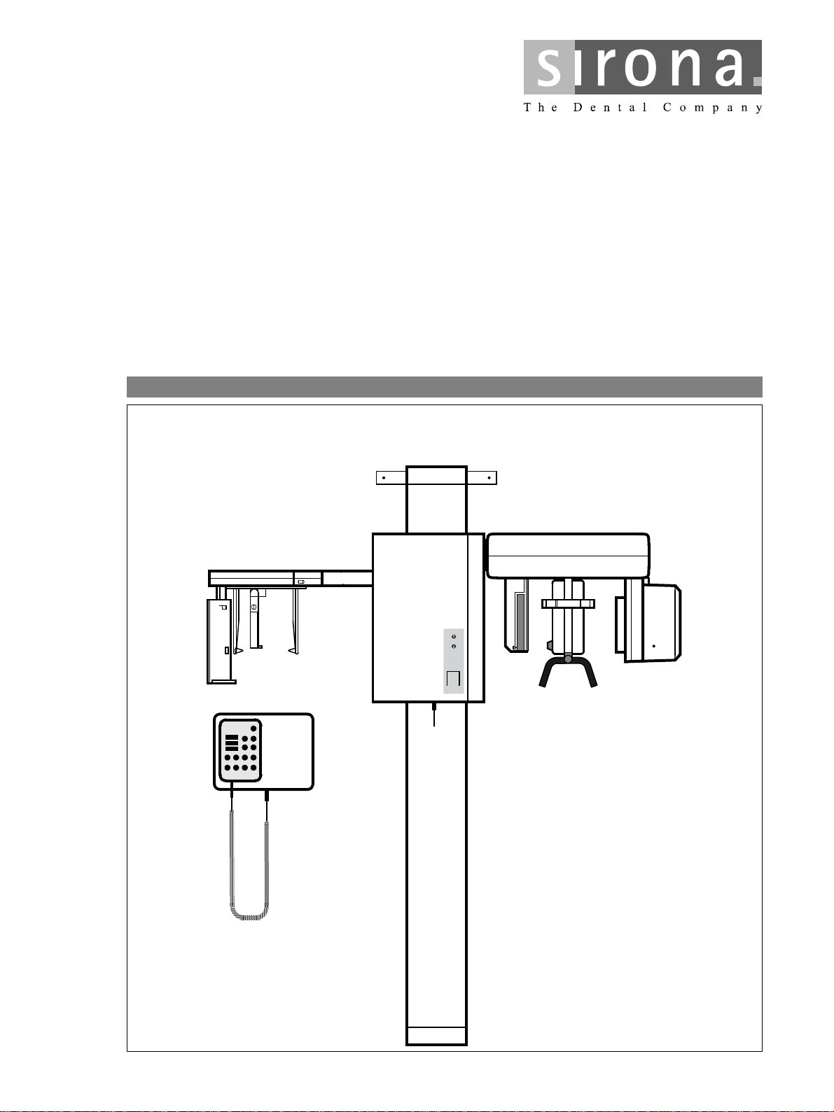
pЙкобЕЙ=j~ем~д= î~äáÇ=Ñêçã=ëÉêá~ä=åçK=UMMM
~åÇ=Сзк=гзЗбСбЕ~нбзе=нз=loqelmelp=P=ap
sЙклбзе=SKM
Page 4

The following are also required:
• Spare parts list
Order no. 33 33 908
• Circuit diagrams
ORTHOPHOS 3 / 3 Ceph / 3 DS
Order no.59 01 629
• Tools
– Hexagonal-head screwdrivers, angled, sizes 1, 5, 2 – 10
– Allen key, size 4, length 200 mm, for socket head screws
– Set of hexagonal wrenches, sizes 4 – 14 with 1/4” ratschet, extension and
4 socket head (Allen) inserts 3 – 6 mm
– Spirit level
– Open-end wrenches, sizes 5.5, 7, 8, 10, 13, 30, and 19, 22 for Ceph
– Torx screwdrivers, sizes 10, 20, 25
– Phillips-head srewdriver, size 1
– Insulated slot-head screwdrivers, sizes 0, 1, 2, 3, 4, 6
– Pliers for retaining ring
• Auxiliary equipment
– Digital multimeter, accuracy class 1
– Soldering iron for cable repairs
– Diagonal cutter
– Cable ties
– Teflon insulating tape
Page 5
Important Notes 1
List of Messages
Troubleshooting
Checks and Adjustments
2
3
4
Service Routines 5
Repairs
Maintenance
6
7
Page 6

Page 7

Contents
1 Important Notes...................................................................................................................1 - 1
1.1 Important Notes ......................................................................................................... 1 - 3
1.2 List of software versions ........................................................................................... 1 - 5
1.3 Major Assemblies and Components .......................................................................... 1 - 6
1.4 Removing Panels ...................................................................................................... 1 - 8
1.5 Photographs of PC Boards ...................................................................................... 1 - 11
2 List of Messages...................................................................................................................2 - 1
2.1 List of Help Messages ............................................................................................... 2 - 3
2.2 List of Error Messages .............................................................................................. 2 - 4
2.3 List of Service Routines ............................................................................................. 2 - 8
2.4 List of Error Messages for SIDEXIS .......................................................................... 2 - 9
3 Troubleshooting....................................................................................................................3 - 1
3.1 Unit cannot be switched on, nothing displayed on the Multitimer .............................. 3 - 7
3.1 A Exposure too dark .................................................................................................. 3 - 7.4
3.2 Demonstration mode cannot be turned ON/OFF ...................................................... 3 - 9
3.3 The Teleradiography exposure is not released ....................................................... 3 - 11
3.4 Correcting errors of help messages H3 04. ............................................................. 3 - 13
3.5 Correcting errors of help messages H3 06. ............................................................. 3 - 15
3.6 Correcting errors of help messages H3 11. ............................................................. 3 - 17
3.7 Correcting error of messages E1 01, E1 02, E2 03: Signal paths to
control board DX1 are interrupted. .......................................................................... 3 - 19
3.8 Correcting error of message E2 01: X-ray tube assembly overheated. .................. 3 - 21
3.9 Correcting error of message E2 04: Zero power range has been re-initialized. ...... 3 - 23
3.10 Correcting error of message E2 11: Anode voltage too high. ................................. 3 - 25
3.11 Correcting error of message E2 12: Anode current too high. .................................. 3 - 27
3.12 Correcting error of message E2 13: Filament voltage too high. .............................. 3 - 29
3.13 Correcting error of message E2 14: Short-circuit in bridge. ................................... 3 - 31
3.14 Correcting error of message E2 16: kV
3.15 Correcting error of message E2 20: Interrupted exposure lead in Multitimer cable. 3 - 35
3.16 Correcting error of message E2 40: VH setpoint out of tolerance. .......................... 3 - 39
3.17 Correcting error of message E2 43: VH setpoint out of tolerance. .......................... 3 - 41
3.18 Correcting error of message E2 44: kV setpoint out of tolerance. ........................... 3 - 43
3.19 Correcting error of message E2 45: mA setpoint out of tolerance. ......................... 3 - 45
3.20 Correcting error of messages E3 01, E3 02: Actuator M2 has
not left/reached the tripping position. ...................................................................... 3 - 47
3.21 Correcting error of messages E3 05, E3 06: Cassette carriage has
not left/reached the reference point. ........................................................................ 3 - 49
3.22 Correcting error of message E3 12: Key for height adjustment pressed
during unit self-adjustment. ..................................................................................... 3 - 51
ACTUAL
– Cable is interrupted. ................... 3 - 33
58 35 744 D 3285
D 3285.077.02.06.02 07.2004
VII
Page 8

Contents
3.23 Correcting error of messages E3 32, E3 33: Start position for rotation was
not exited/reached. .................................................................................................. 3 - 53
3.24 Correcting error of message E3 36: Cassette holder was swivelled from
the Pan position during Pan exposure. .................................................................... 3 - 57
3.25 Correcting error of message E3 39 / E3 42: Light barrier for Ceph position
rotation indicates invalid status ............................................................................... 3 - 61
3.26 Correcting error of message E3 46: Position of cassette holder cannot be
determined. ............................................................................................................. 3 - 63
3.27 Correcting error of message E4 01: Exposure aborted by SIDEXIS (with XOP). ... 3 - 65
3.28 Correcting error of message E4 01: Exposure aborted by SIDEXIS (with XAB) ..... 3 - 67
3.29 Correcting error of message E4 06: Fault at one of the supply voltages
(with XOP). .............................................................................................................. 3 - 69
3.30 Correcting error of message E4 06: Fault at one of the supply voltages
(with XAB) ............................................................................................................... 3 - 71
3.31 Correcting error of message E4 08: Aborted by SIDEXIS during radiation
(with XOP) ............................................................................................................... 3 - 73
3.32 Correcting error of message E4 08: Aborted by SIDEXIS during radiation
(with XAB) ............................................................................................................... 3 - 77
3.33 Correcting error of message E4 11: Image receptor not ready for exposure
(with XOP). .............................................................................................................. 3 - 81
3.34 Correcting error for message E4 11: Image receptor not ready for exposure
(with XAB) ............................................................................................................... 3 - 85
3.35 Correcting error of message E4 16: Active signal present when switching ON
(with XOP). .............................................................................................................. 3 - 89
3.36 Correcting error of message E4 16: Active signal present when switching ON
(with XAB) ............................................................................................................... 3 - 91
4 Checks and Adjustments......................................................................................................4 - 1
4.1 Phantom radiograph — Adjusting actuator M2 ......................................................... 4 - 5
4.2 Checking and adjusting the X-ray beam for Panorama radiography ...................... 4 - 13
4.3 Checking and adjusting the X-ray beam for Cephalometry ..................................... 4 - 17
4.4 Checking the symmetry on the Cephalometer ........................................................ 4 - 19
4.5 Checking and adjusting the ear olives .................................................................... 4 - 21
4.6 X-ray tube assembly: action to be taken during/after replacement? ....................... 4 - 23
4.7 Radiographic density of spinal column not correct .................................................. 4 - 25
4.8 Checking exposure times ........................................................................................ 4 - 27
4.9 Checking the tube current ....................................................................................... 4 - 29
4.10 Adjusting board DX1 ............................................................................................... 4 - 31
4.11 Checking and adjusting the light localizers ............................................................. 4 - 33
58 35 744 D 3285
VIII D 3285.077.02.06.02 07.2004
Page 9

Contents
5 Service Routines ..................................................................................................................5 - 1
5.1 Selecting Service routines ......................................................................................... 5 - 7
5.2 Setting exposure readiness on the PC ...................................................................... 5 - 9
5.3 Service routine S.01 Radiation without rotation ...................................................... 5 - 11
5.4 Service routine S.02 Radiation without rotation for Ceph ........................................ 5 - 13
5.5 Service routine S.03 Setpoints: kV, mA, preheating ................................................ 5 - 15
5.6 Service routine S.04 Actual values: kV, mA, preheating ......................................... 5 - 19
5.7 Service routine S.05 Heating adjustment ................................................................ 5 - 23
5.8 Service routine S.06 Radiation counter (decimal display) ....................................... 5 - 27
5.9 Service routine S.07 Erasing the error memory ...................................................... 5 - 29
5.10 Service routine S.09 Erasing EEPROM DX1 .......................................................... 5 - 31
5.11 Service routine S.11 Setting the kV increase correction value for
Panorama radiography ............................................................................................ 5 - 33
5.12 Service routine S.13 Hardware service ................................................................... 5 - 35
5.13 Service routine S.14 Rotation functions .................................................................. 5 - 37
5.14 Service routine S.15 Checking the actuator M2 ...................................................... 5 - 41
5.15 Service routine S.16 Film holder service ................................................................. 5 - 45
5.16 Service routine S.17 Unit identification ................................................................... 5 - 49
5.17 Service routine S.18 Checking the height adjustment ............................................. 5 - 51
5.18 Service routine S.25 Adjusting the film/screen combination or the
kVmA step series .................................................................................................... 5 - 53
5.19 Service routine S.27 Setting country code .............................................................. 5 - 55
5.20 Service routine S.32 Image receptor service: Panorama ........................................ 5 - 57
5.21 Service routine S.35 PC service ............................................................................. 5 - 59
5.22 Service routine S.37 XAB OP service ..................................................................... 5 - 61
6 Repairs.................................................................................................................................6 - 1
6.1 Replacing the rotation motor M1 ............................................................................... 6 - 5
6.2 Replacing the actuator M2 ........................................................................................ 6 - 9
6.3 Replacing the spindle with motor M4 for height adjustment .................................... 6 - 11
6.4 Replacing the cassette holder for Panorama radiography ...................................... 6 - 15
6.5 Replacing the rope and/or the cassette drive motor M3 ......................................... 6 - 17
6.6 Replacing socket contact for image receptor .......................................................... 6 - 21
6.7 Replacing Column Stand ........................................................................................ 6 - 23
6.8 Replacing rotary knob and sensor ejector ............................................................... 6 - 27
6.9 Replacing ring cable L4 ........................................................................................... 6 - 29
58 35 744 D 3285
D 3285.077.02.06.02 07.2004
IX
Page 10

Contents
7 Maintenance.........................................................................................................................7 - 1
7.1 Checking the height adjustment ................................................................................ 7 - 5
7.2 Checking the forehead support ................................................................................. 7 - 7
7.3 Checking the diaphragm wheel ................................................................................. 7 - 9
7.4 Checking the cassette holder .................................................................................. 7 - 11
7.5 Checking the image receptor .................................................................................. 7 - 13
7.6 Checking the light localizer ..................................................................................... 7 - 15
7.7 Checking the conventional cephalometer ............................................................... 7 - 17
7.8 Checking X-ray exposures ...................................................................................... 7 - 19
7.9 Checking the actual kV/mA values and the preheating ........................................... 7 - 21
7.10 Phantom/needle phantom exposure with ORTHOPHOS 3/3 Ceph ........................ 7 - 23
7.11 Phantom/needle phantom exposure with ORTHOPHOS 3 DS/3 Ceph
with Upgrade Kit ...................................................................................................... 7 - 27
7.12 Checking cables for damage ................................................................................... 7 - 29
7.13 Checking the grounding straps ............................................................................... 7 - 31
7.14 Checking the shielding of the cables ....................................................................... 7 - 33
7.15 Checking light barrier housings V1 to V7/ring cable ............................................... 7 - 35
7.16 Checking the flat belt on rotation motor M1 ............................................................ 7 - 37
7.17 Checking the protective ground wire and the unit’s leakage current ....................... 7 - 39
58 35 744 D 3285
X D 3285.077.02.06.02 07.2004
Page 11

1 Important Notes
Page 12

Contents
Important Notes
Contents
1.1 Important Notes ................................................................................................................. 1 - 3
1.2 List of software versions ................................................................................................... 1 - 5
1.3 Major Assemblies and Components .................................................................................. 1 - 6
1.4 Removing Panels .............................................................................................................. 1 - 8
1.5 Photographs of PC Boards .............................................................................................. 1 - 11
58 35 744 D 3285
1 - 2 D 3285.077.02.06.02 07.2004
Page 13
1.1 Important Notes
1.1 Important Notes
• The ORTHOPHOS® 3 / 3 Ceph / 3 DS
operates with the following nominal line voltages: 208V, 230-240V, 50/60 Hz.
The permissible line voltage fluctuations
The internal line resistance
• Remote control
The unit can be equipped with a remote control inside the treatment room or outside an X-ray room.
For the tests the Multitimer can/must be removed from the remote control module and is to be connected directly to the
unit (for remote control with the Multitimer without coiled cable, the coiled cable has to be connected for the tests according to the installation instructions).
Remember that the fault can then be in the deactivated cable.
• Warm-up time, self-adjustment, cool-down time,
After power-up the unit always requires a warm-up time of one minute.
During this time, the self-adjustment routine for the mechanical elements and electronics of the unit is executed. Pressing
a key during the self-adjustment causes an error indication at the Multitimer. The cool-down time between two consecutive exposures is ensured by the automatic exposure blockage determined by the pulse/pause ratio. The count down of
the waiting time required is indicated on the Multitimer. The turn-off time of board XAB-OP must be at least 60s; otherwise
the unit will not function correctly (no exposure readiness).
• For demonstration units
Now, no X-ray radiation is generated.
In the interest of improved safety we recommend removing fuse F5 on board DX3.
must not exceed 0.8Ω.
set the test switch S1/S88 on board DX31 to position 2. LED V2 on board DX31 must light up.
are 230-240V + 6%, –10%, and 208 V ± 10%.
turn-off time
1.1
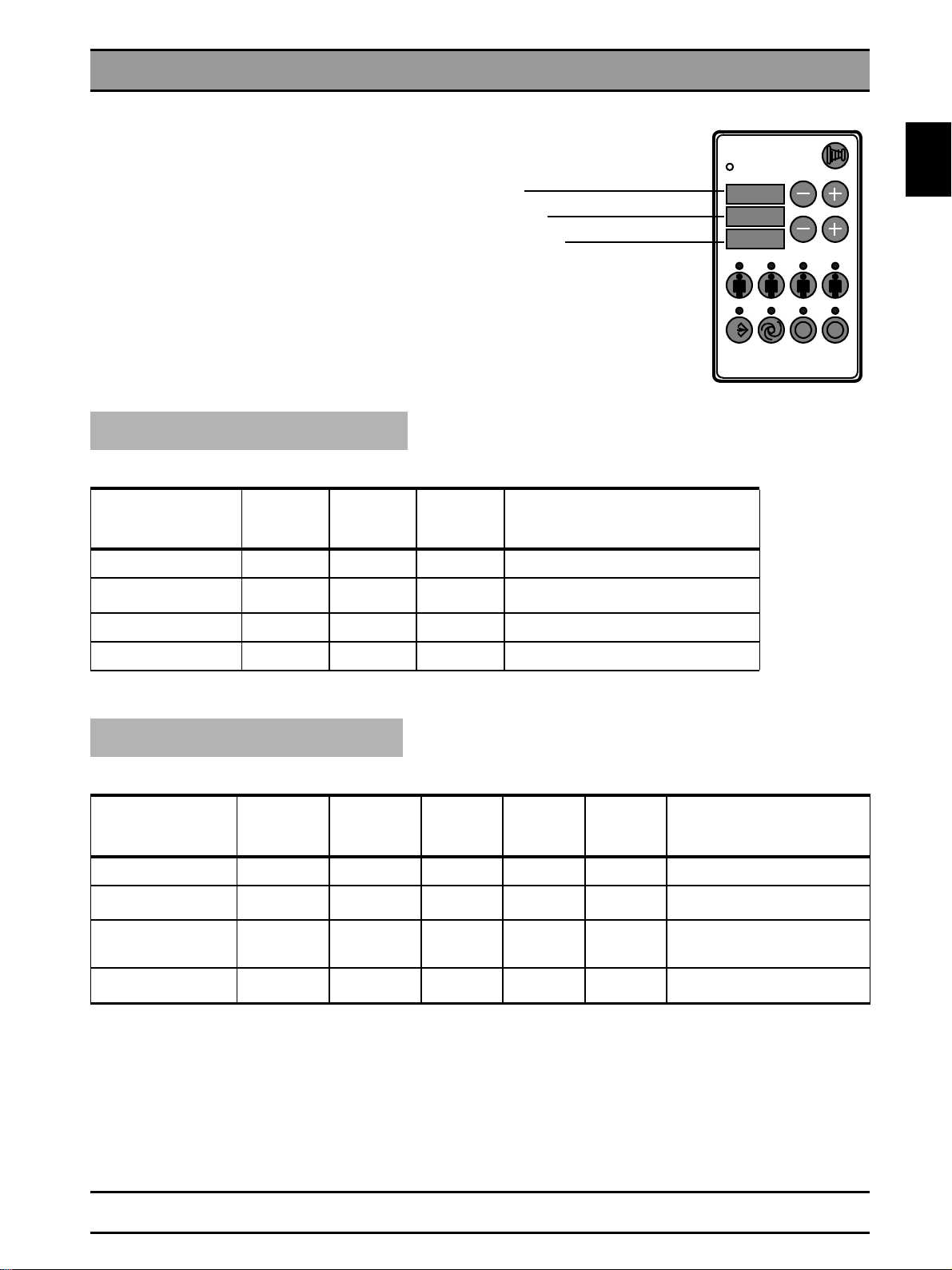
• The overall software v ersion
Multitimer D4 as well as the version number of the memory card. Refer to the list of software versions. When switching
the unit ON the versions are indicated on the Multitimer for about three seconds after the segment test.
• Interference of radio telephones with electromedical equipment
The use of mobile telephones in the area of the medical practice or clinic is prohibited in order to ensure the
operational reliability and safety of electromedical equipment.
• Disposal
The X-ray tube assembly contains a tube which can implode, a small amount of beryllium, a lead lining and mineral oil.
• Error messages
Error messages are indicated on the Multitimer.
• Help messages H if radiographic readiness is not reached
Help messages are displayed on the Multitimer.
of the unit is determined by the software versions of the EPROMs on board DX1 and of the
58 35 744 D 3285
D 3285.077.02.06.02 07.2004
1 - 3
Page 14
1.1 Important Notes
• If you have to remove panels from the unit.
Refer to section "Removing panels".
With the panels removed, remember that the direct incidence of sunshine or bright room light can cause unit malfunctions
by activating the light barriers.
Therefore: Avoid direct sunshine and bright lighting above the unit
Remember when reattaching the panels:
Secure sheet metal covers with screws.
IMPORTANT: For reasons of EMC it is essential
Reinstall all panels.
• Measurements
Before connecting a measuring instrument, always switch the unit OFF.
Select the required current/voltage type and set the measuring range according to the expected value.
Carry out continuity tests only with the unit switched off.
If the release of several exposures with radiation is required for checking the measuring results, you must observe the
specified cool-down intervals. This is ensured by the automatic exposure blockage (see Operating Instructions).
The pulse/interval ratio is 1:10, which means a 10 second pause has to follow after 1 second of radi ati on. This pul se/i nterval ratio is automatically guaranteed by the automatic exposure blockage.
However, preferable for the X-ray tube is a pulse/pause ratio of 1:20.
Adhere to the radiation protection guidelines before generating radiation.
Test runs initiated by pressing the T key on the Multitimer followed by actuation of the exposure release button are executed without radiation, i.e. the kV/mA displays remain blank. l
to insert all screws.
!
• Replacing parts
Always turn the unit OFF before replacing any parts.
When parts located close to the line transformer are to be replaced, switch off the power at the distributor box for the onsite electrical system for safety reasons
WARNING! The discharge time for the capacitors is 4 minutes.
To protect electrostatic sensitive devices (ESD) on boards, always
wear the wrist band.
The unit must be checked and newly adjusted following the replacement of the DX1 electronics,
the X-ray tube assembly or a diaphragm.
The article numbers for ordering spare parts can be found in the spare parts list, order no. 33 33 908.
The figures in the spare parts list offer valuable assistance when replacing parts.
.
58 35 744 D 3285
1 - 4 D 3285.077.02.06.02 07.2004
Page 15
1.2 List of software versions
1.2 List of software versions
From serial no. 8000
for ORTHOPHOS 3 / 3 Ceph / 3 DS
From serial no. 6000
for systems modified to ORTHOPHOS 3 DS
IMPORTANT: No other combinations of software are allowed since these could result in
undefined faults.
ORTHOPHOS 3 / 3 Ceph
Unit identification 30
Overall software DX1
Version
7.30 04.99
8.30 03.01
Version
9.30 05.02
Version
J115
020 006 010
020 006 011 kv/mA levels for Asia and USA;
021 006 011
D4
EEPROM J4
Memory
Card
Multitimer
Version no. memory card
Software Multitimer D4
Software board DX1
Remarks
Anomaly level -1 for P1 and P11 for Asia
0 I 0
kV
0 6
mA
2 0
X-RAY
T
1.2
R
ORTHOPHOS 3 DS
Unit identification 31
Overall software DX1
EEPROM
J115
Version
01.31 04.99
02.31 11.00
Version
Version
03.31 03.01
Version
04.31 05.02
D4
EEPROM J4
020 006 010
020 006 011
020 006 012
021 006 012
Memory
Card
SIDEXIS Service
disk
≥ 4.2
≥ 4.2
≥ 4.2
≥ 4.2
1.12
1.12 XAB OP capable;
1.12 kv/mA levels for Asia and USA;
1.12 Correcting error of message
Remarks
conventional Ceph possible
Anomaly level -1 for P1 and P11
for Asia
E4 04, E3 48
58 35 744 D 3285
D 3285.077.02.06.02 07.2004
1 - 5
Page 16
1.3 Major Assemblies and Components
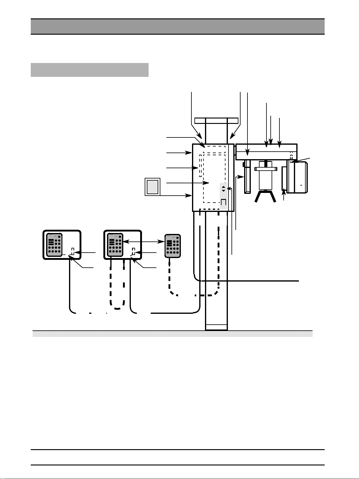
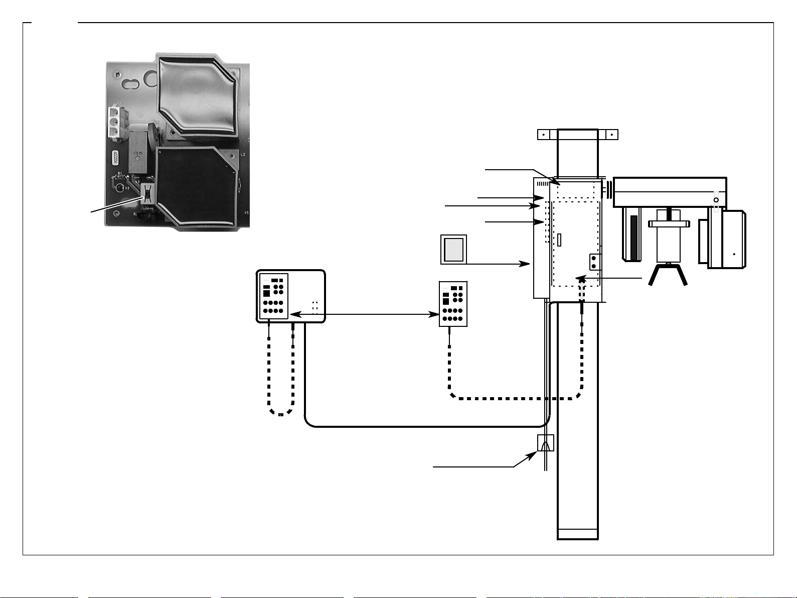
1.3 Major Assemblies and Components
ORTHOPHOS 3 DS
DEB discontinued as of serial no.
31 000 ORTHOPHOS 3 DS
and replaced by XAB OP, XAB D
Remote control . . .
K10
L11
DX33
XAB OP/XAB D / DEB
Rear
DX31
T
DX3
DX1
I
O
S1 with
automatic
cutout
D4
K10
L12
S2, S3,
K2K2
M4
S4
Rear
EDC/BE
S7
S8
RHB
M1
V1
M2
V2
K3
H1
S9
K11
. . . without
coiled cable
BE = Image receptor
DEB, EDC,
RHB, D, DX,
XAB = PC boards
T = Transformer
M = Memory card
H1 = X-ray tube assembly
M1 = Motor for rotation
M2 = Actuator
M4 = Motor for height adjustment
K = Connector/terminal strips on/in the unit
L = Leads/cables
S = Switch
. . . with
coiled cable
L9
K2
L8
Control cable of
L9
remote control
L30/L31/LAN
L8
X = Connectors on boards
V1 - V2 = Light barriers:
V1 = Start position for rotation
V2 = Start position for actuator M2
58 35 744 D 3285
1 - 6 D 3285.077.02.06.02 07.2004
Page 17
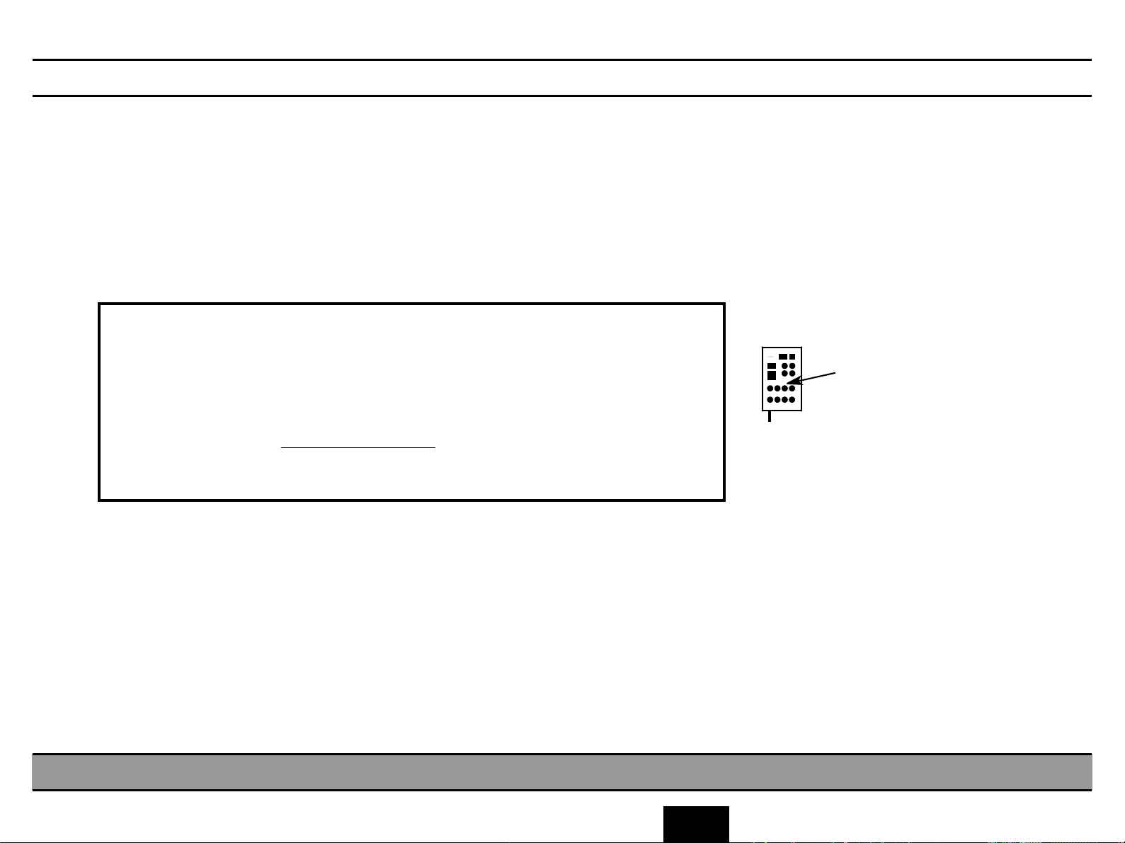
1.3 Major Assemblies and Components
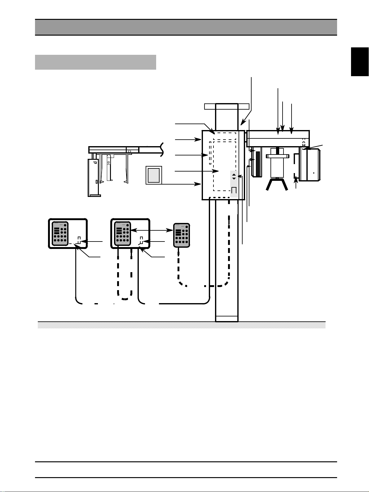
ORTHOPHOS 3 / 3 Ceph
Remote control . . .
K10
L11
I
O
D4
K10
L12
DX31
T
DX3
DX1
S1, F1, F2
or S1 with
automatic
cutout
S2, S3,
K2
M4
S4
rear
S7
S8
V4, V5
M3
V3
FH S1
M1
V1, V7
M2
V2
S10
1.3
K3
H1
S9
K11
. . . without
coiled cable
FH = Membrane keyboard
D, DX = PC boards
T = Transformer
M = Memory card
H1 = X-ray tube assembly
F1, F2 = Main fuses
M1 = Motor for rotation
M2 = Actuator
M3 = Motor for cassette movement
M4 = Motor for height adjustment
K = Connector/terminal strip on/in the unit
L = Leads/cables
S = Switch
X = Connectors on boards
. . . with
coiled cable
L9
K2
L8
L9
L8
Control cable of
remote control
V1 - V7 = Light barriers:
V1 = Start position for rotation
V2 = Start position for actuator M2
V3 = Start position for film cassette
V4 = Exposure position cassette holder
V5 = Cassette holder in Ceph position
V7 = Rotation ring in Ceph position
58 35 744 D 3285
D 3285.077.02.06.02 07.2004
1 - 7
Page 18
1.4 Removing P anels
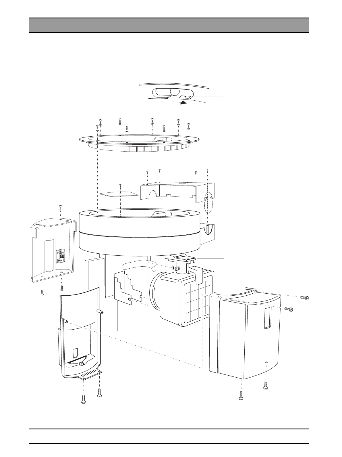
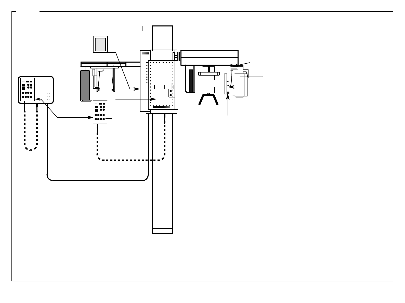
1.4 Removing Panels
X-ray tube assembly, rotation ring
Push this cuff aside before lifting
off the panel!
Don’t forget
cover plate!
Always tighten the four mounting
screws!
58 35 744 D 3285
1 - 8 D 3285.077.02.06.02 07.2004
Page 19
1.4 Removing Panels
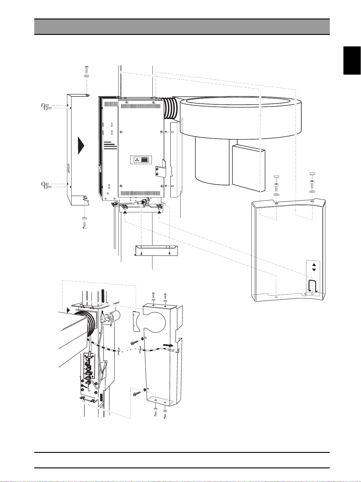
Unit carriage
Left
side
cover
1.4
Side
cover plate
(loosen 2 screws
only to remove)
Bracket
Lowers cover
plate
Front cover
Right
side cover
58 35 744 D 3285
D 3285.077.02.06.02 07.2004
1 - 9
Page 20
1.4 Removing P anels
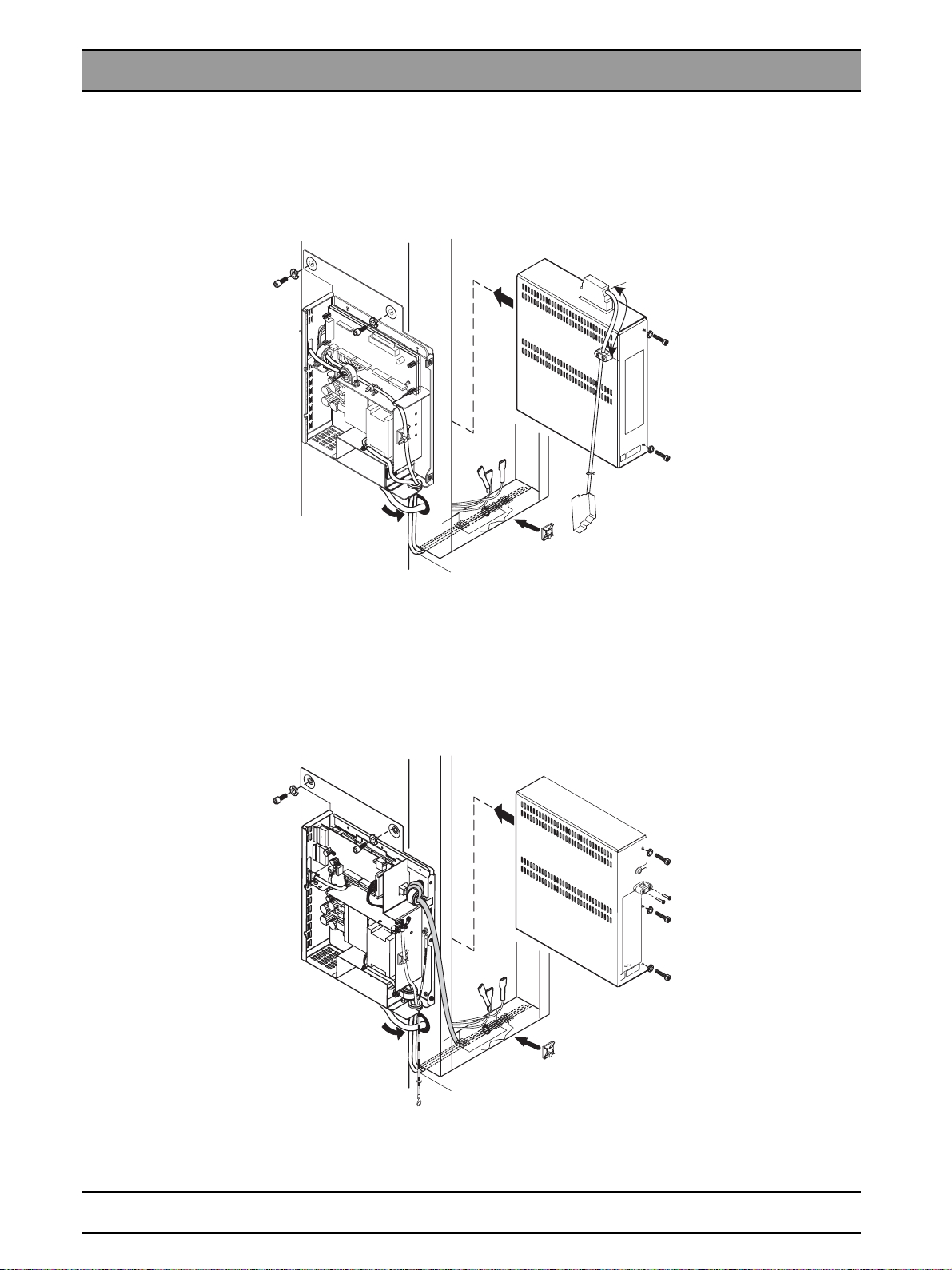
Extension box ORTHOPHOS 3 DS
till Serial-No. 30 999
from Serial-No. 31 000
58 35 744 D 3285
1 - 10 D 3285.077.02.06.02 07.2004
Page 21
1.5 Photographs of PC Boards
1.5 Photographs of PC Boards
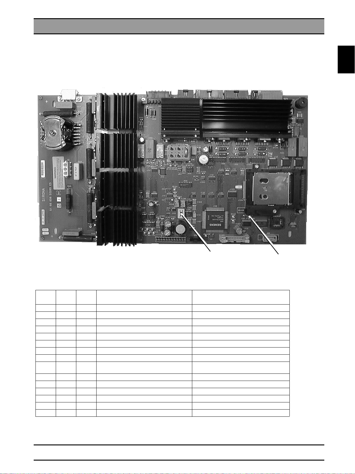
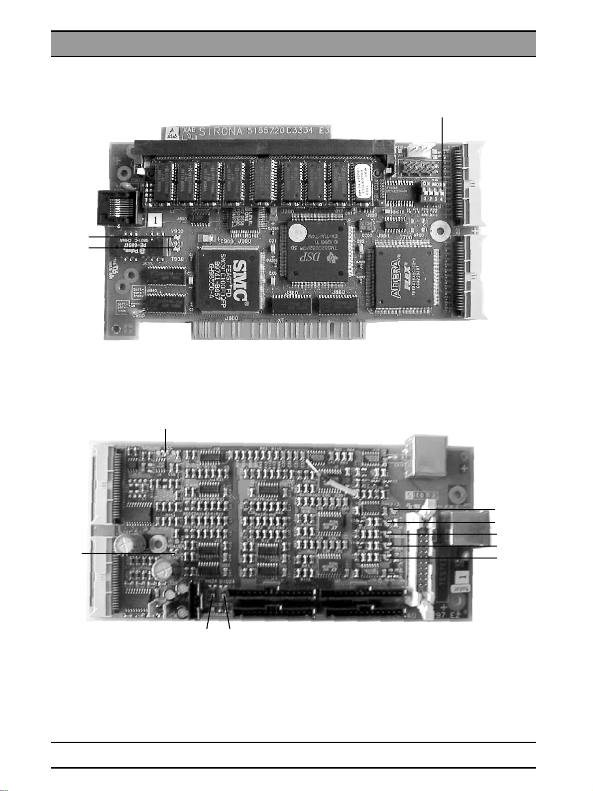
DX1 board
1.5
51 68 658
Switch S101
Position 1 (left)
otherwise system
start-up not possible
with Boot software
LED1
V101
on on on Controller not o.k. Replace and adjust DX1
on off off Internal XRAM not o.k. Replace and adjust DX1
off on off Internal RAM not o.k. Replace and adjust DX1
off off on Program memory for Boot software not o.k. Replace and adjust DX1
flashing flashing off Input clock of 82c54 not o.k. Replace and adjust DX1
flashing off flashing Vref2 voltage not o.k. Replace and adjust DX1
off off flashing Malfunction of Watchdog timer Replace and adjust DX1
off on on Unable to switch to memory card Replace and adjust DX1
flashing off off Program memory of memory card not o.k. Memory card incorrect, not or only partially
off flashing off not assigned
flashing off on not assigned
off flashing on not assigned
off off off All tests run without errors Everything o.k.
on on off No memory card detected Insert memory card correctly
on off on Memory card not correct Insert memory card for ORTHOPHOS
LED2
V103
LED3
V102
Description Required action
programmed
V101 V103 V102
58 35 744 D 3285
D 3285.077.02.06.02 07.2004
1 - 11
Page 22
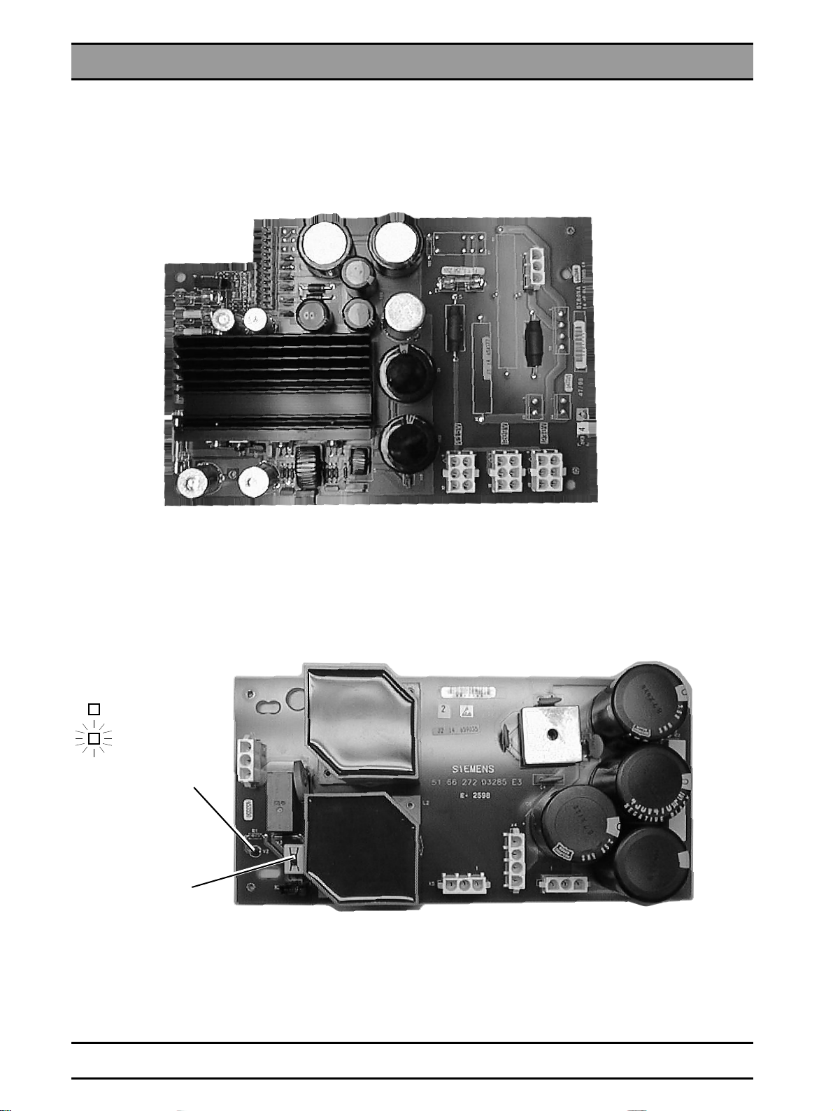
1.5 Photographs of PC Boards
DX3 and DX31 boards
DX3
14 49 011
DX31
51 66 272
Radiation
S.88 Demon-
stration mode
V2
S.88
Position 2
Demonstration
mode
58 35 744 D 3285
1 - 12 D 3285.077.02.06.02 07.2004
Page 23
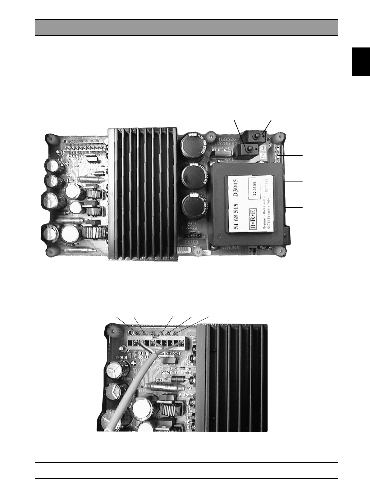
DX33 board
DX33
51 68 526
1.5 Photographs of PC Boards
F1
F2
230V
208V
115V
1.5
F3
V15 V11 V17V16V10V18
+5V+9,5V+24V+24V+30V+30V
58 35 744 D 3285
D 3285.077.02.06.02 07.2004
1 - 13
Page 24
1.5 Photographs of PC Boards
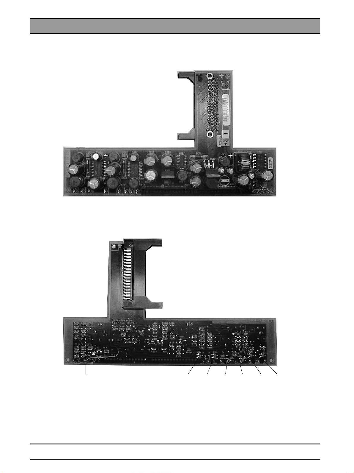
RHB board
RHB
D+5V A+5VA-5VA+24VD+24V+18V-18V
V200 V100 V112V122V212V232V222
58 35 744 D 3285
1 - 14 D 3285.077.02.06.02 07.2004
Page 25
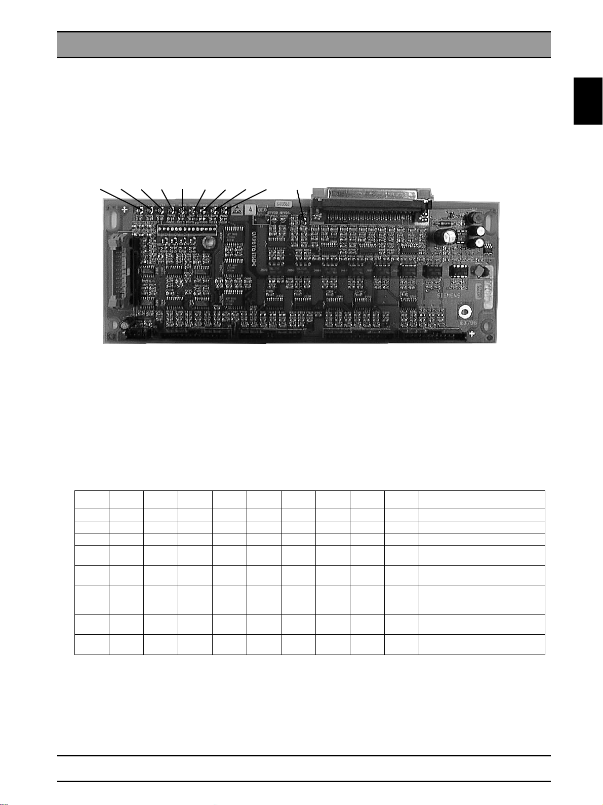
DEB board
DEB
V905 V900 V216V221V910 V670 V350 V232V231
1.5 Photographs of PC Boards
1.5
V950
V216 LED, Out clock pulses TDI
V221 LED, radiographic mode
V231 LED, Ceph radiography mode only with ORTHOPHOS Plus DS Ceph
V232 LED, Panoramic radiography mode
V350 LED, EDC Reset (not inserted)
V670 LED, PC exposure readiness ACTIVE signal
V900 LED, digital supply voltage RHB +24V
V905 LED, analog supply voltage RHB +24V
V910 LED, supply voltage DEB +5V ORTHOPHOS
V950 LED, supply voltage DEB +5V PC
V905 V900 V910 V221 V216 V670 V350 V231 V232 V950 Status
XXXStandby Pan
X X X Standby Ceph without function
X X X X X Panoramic radiography mode
XXX X X
XXXX X XX
XXXX X X X
XXXXglowsX XX
XXXXglowsX X X
Ceph radiography mode
without function
Panoramic radiography mode
Image generation test image
Ceph radiography mode
Image generation test image
without function
Panoramic radiography mode
X-ray
Ceph radiography mode X-ray
without function
58 35 744 D 3285
D 3285.077.02.06.02 07.2004
1 - 15
Page 26
1.5 Photographs of PC Boards
XAB OP and XAB D boards
XAB D
V900
V901
V900 = RD Transmit, GN Receive
V901 = RD Link (adress recognition), GN 100Mbps (Megabits per sec)
Coding switch
XAB OP
V10
V9
V12 V11
V5 LED, TDI distance pulses
V6 LED, IMAGE radiographic mode
V7 LED, radiographic mode Ceph only with ORTHOPHOS Plus DS Ceph
V8 LED, radiographic mode Pan
V9 LED, V continuous
V10 LED, VCC +5V
V11 LED, Digital supply voltage +24V
V12 LED, Analog supply voltage +24V
V13 LED, PC exposure readinesst ACTIVE signal
V13
V5
V6
V7
V8
58 35 744 D 3285
1 - 16 D 3285.077.02.06.02 07.2004
Page 27

2 List of Messages
Page 28

Contents
List of Messages
Contents
2.1 List of Help Messages ................................................................................................... .... 2 - 3
2.2 List of Error Messages ....................................................................................................... 2 - 4
2.3 List of Service Routines ..................................................................................................... 2 - 8
2.4 List of Error Messages for SIDEXIS .................................................................................. 2 - 9
58 35 744 D 3285
2 - 2 D 3285.077.02.06.02 07.2004
Page 29

2.1List of Help Messages
After the cool-down interval has elapsed you want to release an exposure, but the Ready LED is flashing:
• Press the X-ray key on the Multitimer.
CAUTION: Take radiation protection measures.
The H3 or H4 message then appears on the kV/mA display.
• Find in the following list the actions required to return the unit
to readiness for exposure.
• Before
carrying out the required action clear the help message
by pressing the R key on the Multitimer.
Help
message
H3 01
Rotation unit not in the start position. Press the Return key R.
Cassette holder not in Panorama position. Swivel cassette holder to stop position. For error
H3 04
H3 06
Locking button on diaphragm wheel not engaged
(Panorama diaphragm).
Cassette holder not in Ceph position. Swivel cassette holder to stop position. For error
H3 11
H3 12
Panorama or Ceph
H3 20
Rotation unit not in start position for Cephalometry.
Radiographic data not acknowledged. Ackno wledge r a diog r ap hic data with Return k e y R.
Image receptor not inserted correct. Insert image receptor up to end stop.
H4 01
H4 03
H4 10
SIDEXIS
SIDEXIS not ready for exposure. Make SIDEXIS ready for exposure.
Image receptor not suitable for exposure set. Replace the image receptor in the plug-in location
Image could not be transferred to SIDEXIS. Transfer exposure by SiRescue service program
H4 20
Description Required action
correction follow service routine S.16,
5 - 45.
Correctly engage locking button on diaphragm
see page 3 - 15.
wheel,
correction follow service routine S.16,
see page 5 - 45.
Press R key.
For error correction follow service routine S.32,
see page 5 - 57.
See SIDEXIS Service Manual.
according to the programmed acquisition.
to the PC, see SIDEXIS User Manual.
CAUTION Do not switch off the unit until the help
message goes out.
2.1
see page
The above mentioned actions will eliminate help messages caused by operating errors.
If the help message cannot be eliminated by the above actions, the fault is of another nature. Proceed with
troubleshooting as described on the following pages.
58 35 744 D 3285
D 3285.077.02.06.02 07.2004
2 - 3
Page 30
2.2 List of Error Messages
Error
message
E1 01
E1 02
E2 03
Multitimer
E1 03
E2 01
E2 03
E2 04
E2 10
E2 11
E2 12
E2 13
E2 14
E2 15
X-ray tube assembly E2 . . .
E2 16
E2 18
E2 20
E2 35
Description Required action
A key on the Multitimer was pressed during selfadjustment or is defective.
Signal paths to control board D1 are interrupted. Proceed according to section "Correcting error E1
Faulty communication with the unit. Acknowledge the fault by pressing the R key on
Appears upon pressing the exposure button.
Overheated X-ray tube assembly, pulse/pause
ratio not observed.
Proceed according to section "Correcting error E1
see page 3 - 19.
01",
see page 3 - 19.
02,
the Multitimer.
Acknowledge the fault by pressing the R key on
the Multitimer. Allow the X-r ay tube assembly to
cool down. If the error message reoccurs, proceed
according to section "Correcting error E2 01",
see page 3 - 21.
See E1 02 see page 3 - 19
Zero power range has been re-initialized. Acknowledge the fault by pressing the R key on
the Multitimer. Unfortunately, the freely
programmed values will be lost and must be
reprogrammed. If not possible: correct the error
with E2 04,
Max. radiation time of the program exceeded. Only possible in service mode; acknowledge the
fault by pressing the R ke y on the Multitimer.
Does this error occur often? Board DX1 defective
→ replace and perform "Adjusing board DX1",
see page 4 - 31.
kV
(tube voltage) exceeded. Proceed according to section "Correcting error E2
max.
mA
(tube current) exceeded. Proceed according to section "Correcting error E2
max.
VH
(filament voltage) exceeded. Proceed according to section "Correcting error E2
max.
Short-circuit of an output stage on DX1 deactivated.
VH
continuously present. Hardware error, board DX1 defective →
max.
kV
cable is interrupted. Proceed according to section "Correcting error E2
actual
Non-localizable fault in obtaining the DC/AC signals.
Occurs upon pressing the exposure button e.g.
with the X-ray room door contact open - exposure
release lead in the Multitimer cable is broken.
Invalid data in the data memory. Erase data in the EEPROM with 'Service Routine
11",
12", see page 3 - 27.
13", see page 3 - 29.
Proceed according to section "Correcting error E2
14",
replace and perform "Adjusing board DX1", see
page 4 - 31.
16", see page 3 - 33.
Acknowledge the fault by pressing the R key on
the Multitimer. If fault reoccurs, DX1 board is
defective → replace. Perform "Adjusting board
DX1”,
Close X-ray room door. Acknowledge the fault by
pressing the R key on the Multitimer. If the fault
reoccurs, proceed according to section "Correcting error E2 20",
09'. Then press the R key. If the message reoccurs, DX1 board is defective → replace and perform "Adjusting board DX1”,
see page 3 - 23.
see page 3 - 25.
see page 3 - 31.
see page 4 - 31.
see page 3 - 35.
see page 4 - 31.
58 35 744 D 3285
2 - 4 D 3285.077.02.06.02 07.2004
Page 31

2.2 List of Error Messages – Continued
Error
message
E2 40
E2 41
E2 42
E2 43
E2 44
E2 45
E2 46
E2 47
X-ray tube assembly E2 . . .
E2 48
E3 01
E3 02
E3 05
E3 06
E3 08
E3 12
E3 23
Unit E3 . . .
E3 24
Description
VH setpoint out of tolerance ± 10 %. Proceed according to section "Correcting error E2
40", see page 3 - 39.
kV setpoint out of tolerance ± 5 %. Adjust board DX1. If not possible, DX1 board is
defective → replace and adjust,
Required action
see page 4 - 31.
mA setpoint out of tolerance ± 5 %. Adjust board DX1. If not possible, DX1 board is
defective → replace and adjust,
see page 4 - 31.
VH actual value out of tolerance ± 10 %. Proceed according to section ”Correcting error E2
see page 3 - 41.
43",
kV actual value out of tolerance ± 10 %. Proceed according to section ”Correcting error E2
see page 3 - 43.
44",
mA actual value out of tol e rance ± 10 %. Proceed according to section ”Correcting error E2
45", see page 3 - 45.
Error while increasing or decreasing the kV value. Software error or DX1 board defective → replace
and perform "Adjusting board DX1”,
see page 4 - 31.
Incorrect setpoint value after automatic setpoint
adjustment.
Faulty user offset while increasing the kV value. Acknowledge the fault by pressing the R key. Cau-
Operating element for light barrier V3 of actuator
M2 has not left/reached the tripping position.
Cassette carriage has not left/reached the reference point.
Fault in film motor counter. Acknowledge the fault by pressing the R key. If the
Adjust board DX1. If not possible, DX1 board is
defectiv e → replace and perform "Adjusting board
DX1”, see page 4 - 31. EEPROM defective.
tion: If the offset was changed by the user (possible in the range from -6 to +3) it will be reset to
zero. If the fault reoccurs, the DX1 board is defective → replace and perform "Adjusting board
see page 4 - 31.
DX1”,
Proceed according to section "Correcting error E3
01/02", see page 3 - 47.
Proceed according to section "Correcting error E3
05 /06",
fault reoccurs, the DX1 board is defective →
replace and perform "Adjusting board DX1”,
see page 3 - 49.
see page 4 - 31.
Key f or height adjustment ↑↓ was pressed du ring
self adjustment or is defective.
Return key R was pressed during the switch-on
procedure or before completion of unit self-adjustment.
"“X-Ray Control” is indicated at switch-on. a) If error message occurs in combination with
Proceed according to section "Correcting error E3
see page 3 - 51.
12",
Acknowledge the fault by pressing the R key on
the Multitimer.
E1 02: button was recognized on Multitimer as
actuated - check buttons or replace Multitimer.
b) If error message occurs alone, pull out Multitimer and switch on again. If error message occurs
again: DX1 defective → replace and perform
“Adjusting board DX1”,
message no longer occurs: replace Multitimer.
see page 4 - 31. If error
2.2
58 35 744 D 3285
D 3285.077.02.06.02 07.2004
2 - 5
Page 32

2.2 List of Error Messages – Continued
Error
message
E3 25
E3 26
E3 32
E3 33
E3 35
E3 36
E3 37
E3 39
E3 41
E3 42
E3 43
Unit E3 . . .
E3 46
E3 47*
E3 48*
E3 49
E3 50
E3 52
E3 53
Description
Incorrect data for exposure control. Memory card or DX1 defective → replace and per-
form "Adjusting board DX1”,
Data in EEPROM not compatible with software
version of memory card.
Start position for rotation was not exited/reached. Proceed according to section "Correcting error E3
Rotation counter not counting correctly. Software error or DX1 board defective → replace
Check for compatibility of software versions
according to the list,
correct software combination, or the memory card
or DX1 is defective.
32/33", see page 3 - 53.
and perform "Adjusting board DX1”,
Required action
see page 4 - 31.
see page 1 - 5. Install the
see page 4 - 31.
Cassette holder was swivelled from the Pan position during the Pan exposure.
Counter IC of actuators not counting correctly. DX1 board defective → replace and perform
Light barrier for Ceph position rotation indicates
invalid status.
Error with counter for kV increase. DX1 board defective → replace and perform
Rotation has not reached Ceph position. Light barriers V7/V8 maladj usted/defective.
Error with counter for radiation times. DX1 board defective → replace and perform
Position of cassette holder cannot be determined. Proceed according to section "Correcting error E3
Memory card not inserted. Insert memory card.
Inserted memory card invalid. Replace memory card.
Watchdog reset performed. Acknowledge the f ault by pressing the R key. Fault
Proceed according to section "Correcting error E3
36", see page 3 - 57.
"Adjusting board DX1”, see page 4 - 31.
Proceed according to section "Correcting error E3
see page 3 - 61.
39",
"Adjusting board DX1”, see page 4 - 31.
"Adjusting board DX1”,
46", see page 3 - 63.
occurs with voltage fluctuations; if recurs frequently: DX31 or DX1 board is defective →
replace and perform "Adjusting board DX1”,
see page 4 - 31.
see page 4 - 31.
This service exposure is not possible in the demonstration mode.
Unit identification does not match the inserted
memory card.
Deactivate demonstration mode. Turn test switch
S1/S88 on DX31 to position 1. V2 on DX31 must
not light up. Observe section "Demonstration
mode cannot be switched ON/OFF",
3 - 9.
When modifying ORTHOPHOS 3 to 3 DS always
perform Service-Routine S.17, when replacing
DX1 only in case of deviations.
see page
see page 5 - 49.
Switch S101 in right-hand position.
System starts up without Boot software.
Turn switch S101 to left-hand position.
* Is not displayed on all units
58 35 744 D 3285
2 - 6 D 3285.077.02.06.02 07.2004
Page 33
2.2 List of Error Messages – Continued
Error
message
E4 01
E4 06
E4 07
E4 08
E4 10
SIDEXIS
E4 11
E4 12
E4 16
E4 17
E4 18
E4 19
E4 21
–
–
–
– – –
–
–
–
Description Required action
Exposure aborted by SIDEXIS. Proceed according to section "Correcting error E4
01", see page 3 - 65.
Fault at one of the supply voltages. Proceed according to section "Correcting error E4
06", see page 3 - 69.
Fault in TDI pulse generation. DX1 board defective → replace and perform
"Adjusting board DX1”,
Aborted by SIDEXIS during radiation. Proceed according to section "Correcting error E4
08", see page 3 - 73. In service program →
make SIDEXIS ready for exposure;
factory service 2.
Communication fault with image acquisition card
XOP (in PC) or XAB OP (in ORTHOPHOS).
Image receptor not ready for exposure. Proceed according to section "Correcting error E4
Image receptor not logged in. Load contents of image receptor floppy.
Active signal present when switching ON. Check SIDEXIS readiness for exposure. With
Software versions of DX1 and XAB OP boards are
not compatible.
Image receptor could not be addressed prior to
exposure.
A software download of XAB OP is performed (no
acknowledgement of error message possible).
The XAB OP is in the initialization phase (Boot
Service) (proceed as described in SIDEXIS service manual; SIXABCON description). The XAB
OP has no valid IP address.
Indication at Multitimer.
Communication between control board DX1 and
Multitimer / board D4 is faulty.
Indication at Multitimer At every switch-on ca. 2s, if longer: check LED
With image acquisition card XOP: check cable
L30/L31 and DEB board.
With XAB OP: XAB OP does not respond or has
crashed. Switch unit off and on again.
Or not in correct service mode in SIDEXIS.
11", see page 3 - 81. Check signal path from
image receptor to PC.
XOP board: Check line path from XOP board in
PC to DEB/DX1 board.
With XAB OP board: Check line path from DX1
board to XAB OP board.
Proceed according to section "Correcting error E4
see page 3 - 89.
16",
Establish a valid software combination by replac-
ing the memory card; load a new XAB-OP software version (see SIDEXIS service manual);
SIXABCON description.
Proceed according to section "Correcting error E4
see page 3 - 81.
11",
Wait until the 4 LEDs above the patient symbols
start flashing; then switch the unit off. Software
download is completed.
After a valid IP address has been assigned by
SIXABCON the error message can be acknowledged on the unit (R ke y).
Check V3 on Multitimer (Ready to operate). Check
Multitimer cable.
Check line voltage and terminal strip K1. Measure
supply voltage at DX1 X1; if OK, DX1 board is
defective; if not, DX3 or cable is defective.
V101-103. Check memory card.
DX1 board is defective → replace and perform
"Adjusting board DX1”,
see page 4 - 31.
see page 4 - 31.
2.2
58 35 744 D 3285
D 3285.077.02.06.02 07.2004
2 - 7
Page 34

2.3 List of Service Routines
Service
routine
S.01
S.02
S.03
S.04
S.05
S.06
S.07
S.09
S.11
S.13
S.14
S.15
S.16
S.17
S.18
S.25
S.27
S.32
S.35
S.37
S.88
Description When required
Radiation without rotation All adjustments of X-ray tube assembly, e.g. accep-
tance testing, functional test, head adjustment, diaphragm adjustment.
Radiation without rotation for Ceph See S.01.
Adjustment of kV setpoint, mA setpoint and VH set-
point
Test of actual values kV, mA, VH. After replacing DX1 or X-ray tube assembly.
Heating adjustment After replacing DX1 or X-ray tube assembly.
Reading/deleting the radiation counter After replacing the X-ray tube assembly or in war-
Deleting the error memory After replacing the X-ray tube assembly.
Erasing EEPROM on DX1 (deletes all data) In case of software problems (all software adjust-
Adjusting the kV increase to customer’s request Too much kV increase in the spine region.
Hardware service Problems with DX1 board.
Rotation functions Mechanical malfunctions of rotation and test of the
Check of actuator Mechanical malfunctions, layer correction, light bar-
Check of film holder Film holder problems.
Unit identification Changing the unit identification.
Height adjustment Checking freedom of movement.
Adjusting the film/screen combination or the kVmA
step series
Setting country code Change anomaly
Image receptor test, Pan For checking the image receptor.
PC service Problems with readiness for e xpos ure.
XAB OP service Read out and delete IP addresses
Demonstration mode Selected with switch S1 on DX31. Switches the unit
After replacing the DX1 board, or malfunction of the
X-ray tube assembly.
ranty cases
ments are deleted and must be reprogrammed).
light barriers.
rier adjustment.
Change the Program Values
to demonstration mode (no radiation).
58 35 744 D 3285
2 - 8 D 3285.077.02.06.02 07.2004
Page 35

2.4List of Error Messages for SIDEXIS
The following descriptions should always be seen in relation to the ORTHOPHOS 3 DS unit.
With error message E4 01, ORTHOPHOS 3 DS is generally functional and the SIDEXIS messages must be observed. With
other error messages on ORTHOPHOS 3 DS, the SIDEXIS messages indicate secondary faults.
OP : ORTHOPHOS 3 DS
XOP : Image acquisition card for Panorama radiography
EDC : Image receptor electronics on ORTHOPHOS 3 DS
Error
message
up to
SIDEXIS 5.2x
Multitimer
Break 1
Multitimer
Break 2
OP
Break 1
OP
Break 2
EDC
Break XXX
XOP
Break 1/2/3
**
XOP
Break 10 **
XOP
Break 30
XOP
Break 40
XOP
Break 50 **
XOP
Break
60/70
Error
message
from
SIDEXIS 5.3
Multitimer
Break
0xA001
Multitimer
Break
0xA002
OP Break
0xB001
OP Break
0xB002
EDC Break
0xCxxx
XAB OP
Break
0xD001/002/
003 **
XAB OP
Break
0xD010 **
XAB OP
Break
0xD030
XAB OP
Break
0xD040
XAB OP
Break
0xD050 **
XAB OP
Break
0xD060/070
Description
Interruption caused by releasing the X-ray
button on the Multitimer during radiation.
Interruption caused by releasing the X-ray
button on the Multitimer between two partial exposures.
Interruption by OP. Check error message on Multitimer.
Interruption by OP. Check error message on Multitimer.
Voltage problem/failure at image receptor,
see Appendix A.
Timeout on the XOP/XAB, no defined functional call from OP within a preset time.
(only for ORTHOPHOS Plus DS Ceph)
Incorrect communication between XOP/
XAB and image receptor.
OP pulses are more than intended for the
exposure.
Image acquisition card holds insufficient
storage space for the intended exposure.
Image acquisition card receives no image
information.
ORTHOPHOS emits incorrect exposure ID. Check the software versions of OP and
The displayed number XXX is an indication
of several error numbers, see Appendix A.
Check for mechanical obstruction of the
OP movement.
Check the software version of OP and
SIDEXIS for compatibility.
Remove the image receptor from its holder
and reinsert it firmly.
Check signal path with XOP:
XOP – cable connection – OP – image
receptor.
Check signal path with XAB:
XAB – image receptor.
Check the voltages at the image receptor.
Check the software versions of OP and
SIDEXIS for compatibility. Check whether
OP is "hung up".
Check the software versions of OP and
SIDEXIS for compatibility.
Check the memory configuration of XOP/
XAB.
Remove EDC from its holder and reinsert it
firmly. Check the signal path:
Check signal path with XOP:
XOP – cable connection – OP – image
receptor.
Check signal path with XAB:
XAB – image receptor.
Check the voltages at the image receptor.
SIDEXIS for compatibility.
Check the error message displayed by the
OP. (data or address bus error?)
Required action
2.4
** see Correcting error of message E4 08 and E4 01.
58 35 744 D 3285
D 3285.077.02.06.02 07.2004
2 - 9
Page 36

2.4 EDC Break Annex A
The error message indicates a combination of several fault causes:
e.g. display on SIDEXIS 3 ¦ C
HEX 3 C
Valence
8
3
2
4
2
2
2
1
2
1
0
2
8
3
2
4
2
2
2
1
2
1
0
2
Bit76543210
Error
EDC
RESET
EDC
VSP
EDC
VSN
EDC
VDD
EDC
VAN
EDC
VAP
001 1 1 100
These voltages are not present
Bit = 0 Ok, fault has not occurred
Bit = 1 Error, fault has occurred, signal is missing
Bit number Error
0
1
2
3
4
5
EDC VAP ERROR V212 0x01 Voltage VAP +18 V not present/too low
EDC VAN ERROR V232 0x02 Voltage VAN – 18 V not present/too low
EDC VDD ERROR ------- 0x04 Voltage VDD not present/too low
EDC VSN ERROR V122 0x08 Voltage VSN – 5 V not present/too low
EDC VSP ERROR V112 0x10 Voltage VSP +5 V not present/too low
EDC RESET ERROR V222 0x20 Voltage VCC +5 V not present/too low
6
7
LED
RHB
Meaning
or digital section is in reset state
0x40 Inte rnal message
0x80 Inte rnal message
58 35 744 D 3285
2 - 10 D 3285.077.02.06.02 07.2004
Page 37

3 Troubleshooting
Page 38

Contents
Troubleshooting
Contents
3.1 Unit cannot be switched on, nothing displayed on the Multitimer ...................................... 3 - 7
3.1 A Exposure too dark ........................................................................................................... 3 - 7.4
3.2 Demonstration mode cannot be turned ON/OFF ............................................................... 3 - 9
3.3 The Teleradiography exposure is not released ............................................................... 3 - 11
3.4 Correcting errors of help messages H3 04. ..................................................................... 3 - 13
3.5 Correcting errors of help messages H3 06. ..................................................................... 3 - 15
3.6 Correcting errors of help messages H3 11. ..................................................................... 3 - 17
3.7 Correcting error of messages E1 01, E1 02, E2 03: Signal paths to control
board DX1 are interrupted. .............................................................................................. 3 - 19
3.8 Correcting error of message E2 01: X-ray tube assembly overheated. ........................... 3 - 21
3.9 Correcting error of message E2 04: Zero power range has been re-initialized. .............. 3 - 23
3.10 Correcting error of message E2 11: Anode voltage too high. .......................................... 3 - 25
3.11 Correcting error of message E2 12: Anode current too high. .......................................... 3 - 27
3.12 Correcting error of message E2 13: Filament voltage too high. ...................................... 3 - 29
3.13 Correcting error of message E2 14: Short-circuit in bridge. ........................................... 3 - 31
3.14 Correcting error of message E2 16: kV
3.15 Correcting error of message E2 20: Interrupted exposure lead in Multitimer cable. ....... 3 - 35
ACTUAL
– Cable is interrupted. ............................ 3 - 33
58 35 744 D 3285
3 - 2 D 3285.077.02.06.02 07.2004
Page 39

Contents
3.16 Correcting error of message E2 40: VH setpoint out of tolerance. .................................. 3 - 39
3.17 Correcting error of message E2 43: VH setpoint out of tolerance. .................................. 3 - 41
3.18 Correcting error of message E2 44: kV setpoint out of tolerance. ................................... 3 - 43
3.19 Correcting error of message E2 45: mA setpoint out of tolerance. .................................. 3 - 45
3.20 Correcting error of messages E3 01, E3 02: Actuator M2 has not left/reached
the tripping position. ........................................................................................................ 3 - 47
3.21 Correcting error of messages E3 05, E3 06: Cassette carriage has not left/reached
the reference point. .......................................................................................................... 3 - 49
3.22 Correcting error of message E3 12: Key for height adjustment pressed during
unit self-adjustment. ........................................................................................................ 3 - 51
3.23 Correcting error of messages E3 32, E3 33: Start position for rotation was
not exited/reached. .......................................................................................................... 3 - 53
3.24 Correcting error of message E3 36: Cassette holder was swivelled from the Pan
position during Pan exposure. ......................................................................................... 3 - 57
3.25 Correcting error of message E3 39 / E3 42: Light barrier for Ceph position rotation
indicates invalid status ..................................................................................................... 3 - 61
3.26 Correcting error of message E3 46: Position of cassette holder cannot be determined. 3 - 63
3.27 Correcting error of message E4 01: Exposure aborted by SIDEXIS (with XOP). ............ 3 - 65
3.28 Correcting error of message E4 01: Exposure aborted by SIDEXIS (with XAB) ............. 3 - 67
3.29 Correcting error of message E4 06: Fault at one of the supply voltages (with XOP). ..... 3 - 69
3.30 Correcting error of message E4 06: Fault at one of the supply voltages (with XAB) ....... 3 - 71
3.31 Correcting error of message E4 08: Aborted by SIDEXIS during radiation (with XOP) ... 3 - 73
3.32 Correcting error of message E4 08: Aborted by SIDEXIS during radiation (with XAB) ... 3 - 77
3.33 Correcting error of message E4 11: Image receptor not ready for exposure (with XOP). 3 - 81
3.34 Correcting error for message E4 11: Image receptor not ready for exposure (with XAB) 3 - 85
3.35 Correcting error of message E4 16: Active signal present when switching ON (with XOP). 3 -
89
3.36 Correcting error of message E4 16: Active signal present when switching ON (with XAB) . 3 -
91
58 35 744 D 3285
D 3285.077.02.06.02 07.2004
3 - 3
Page 40

Contents
58 35 744 D 3285
3 - 4 D 3285.077.02.06.02 07.2004
Page 41

Personal notes
58 35 744 D 3285
D 3285.077.02.06.02 07.2004
3 - 5
Page 42

3 - 6
F Spare
DX31
Transformer
DX3 X9
Remote control
Multitimer MT
Control cable of
remote control
ON
OFF
I
O
Line connection
S1, F1, F2
or S1 with
automatic
cutout
X1
DX1
Page 43

CAUTION: Always switch the unit OFF before connecting a measuring instrument or replacing any components!
• Is the line voltage present at the wall socket?
• Are the line fuses F1 and F2 (if available) in order? If not: always replace both fuses.
• Is the voltage supply o.k., but the Multitimer stays dark nevertheless? See fault localization next page.
D 3285.077.02.06.02 07.2004
58 35 744 D 3285
Switch ON
main switch S1
Position I
Measure line voltage
at fuses F1, F2:
(if present) or at S1 with
automatic cutout:
Line voltage
yes
DX3
Do LEDs V10-V14
on board DX3
light up?
yes
DX3
Supply voltages
present on DX1?
yes
no
no
partly
no
CAUTION: line voltage
Connection to wall socket is interrupted.
Check:
• Fuses F1, F2
• Main switch S1
• Terminal strip K1
• Power cable to wall socket
• Line filter
• DX31
Fuse F1 (DX3) or DX3 defective or Transformer
Replace fuse in failed circuit and trigge r fuse again,
replace DX3
L1A or DX1 defective
Check L1A for continuity
I
O
S1
S1
with automatic
cutout
K1
DX3/DX31
Filter
F1
N
L
V∼
Mains
F2
Ferrite
K1
DX1,
check Multitimer and
Remote and replace if
required.
3.1 Unit cannot be switched on, nothing displayed on the Multitimer
3 - 7
3.1
Page 44

3 - 7.1
DX1
LED1
V101
on on on Controller not o.k. Replace and adjust DX1
on off off Internal XRAM not o.k. Replace and adjust DX1
off on off Internal RAM not o.k. Replace and adjust DX1
off off on Program memory for Boot software not o.k. Replace and adjust DX1
flashing flashing off Input clock of 82c54 not o.k. Replace and adjust DX1
flashing off flashing Vref2 voltage not o.k. Replace and adjust DX1
off off flashing Malfunction of Watchdog timer Replace and adjust DX1
off on on Unable to switch to memory card Replace and adjust DX1
flashing off off Program memory of memory card not o.k. Memory card incorrect, not or only partially
off flashing off not assigned
flashing off on not assigned
off flashing on not assigned
off off off All tests run without errors Everything o.k.
on on off No memory card detected Insert memory card correctly
on off on Memory card not correct Insert memory card for ORTHOPHOS
LED2
V103
LED3
V102
Description Required action
programmed
Switch S101
Position 1 (left)
otherwise system
start-up not possible
with Boot software
V101 V103 V102
Page 45

CAUTION: Always switch the unit OFF before connecting a measuring instrument or replacing any components!
Does the unit fail to per-
form a complete self-ad-
justment after power-up
and the Multitimer stays
dark?
yes
After power-up the unit always requires a warm-up time of one minute.
During this time, the self-adjustment routine for the mechanical elements and electronics of the unit is executed and than the versions ar e
indicated on the Multitimer for about three seconds after the segment
test. The overall software version of the unit is determined by the software versions of the EPROMs on board DX1 and of the Multitime r D4
as well as the version number of the memory card.
no
Observe Multitimer display
D 3285.077.02.06.02 07.2004
58 35 744 D 3285
Do LEDs V101 and V103
on DX1 light up after the
self-adjustment?
no
Do LEDs V101 and V102
on DX1 light up after the
self-adjustment?
no
Do LEDs V101, V102 and
V103 on DX1 light up in
varying order and go out
at the end of the self-ad-
yes
Memory card not correctly inserted.
Insert memory card correctly.
yes
Inserted memory card invalid.
Replace memory card.
justment?
yes
Nothing displayed on the
Multitimer?
yes
Check Multitimer and Multitimer
cable and replace, if necessary
3.1 Unit cannot be switched on, nothing displayed on the Multitimer
3 - 7.2
3.1
no
no
see Table
Observe Multitimer display
Page 46

3 - 7.3
Remote control
Multitimer MT
Control cable
Remote control
ON
OFF
O
I
X-ray tube assembly
DX1
RkV / R
Hz
Page 47

CAUTION: Always switch the unit OFF before connecting a measuring instrument or replacing any components!
• The processing equipment is in working order.
• The X-ray radiation indicator lights up and the acoustic signal is emitted when the release button is pressed.
• The X-ray beam is correctly adjusted. See chapter entitled 'Checking and adjusting the X-ray beam for panoramic exposures'.
• The mA meter must be in working order , i.e. it must have been chec ked on a functioning OR THOPHOS 3.
Measure tube current:
'Checking the tube current'.
Check kV value with MINI X kV meter:
• Fasten kV meter to secondary diaphragm:
• Rotate empty window of diaphragm wheel in front of beam path.
• Select Service routine S.02 was described in the chapter 'Selecting the Ser-
• Set the radiation time to 2 seconds and the power to 70kV on the m ultitimer.
• Release RADIATION and read off the kV value on the kV meter.
See chapter on
Are 10mA±0,5mA attained?
yes
no
Replace board DX1 and
• 'Adjust board DX1'
Sensor area in beam path (slot).
(Remove lokking screw A for this purpose. Not available on
ORTHOPHOS 3C).
vice routine'.
D 3285.077.02.06.02 07.2004
58 35 744 D 3285
No display on the kV meter.
Is the sensor area properly
(fully) illuminated?
3.1 AExposure too dark
3 - 7.4
yes
no
Correct position of kV meter.
Check exposure.
3.1
1
PAN15x30cm
A
PAN 6x12 in.
Page 48

3 - 7.5
Remote control
Multitimer MT
Control cable
Remote control
ON
OFF
O
I
X-ray tube assembly
DX1
RkV / R
Hz
Page 49
CAUTION: Always switch the unit OFF before connecting a measuring instrument or replacing any components!
DX1
Can the kV value be set to
the lower tolerance limit of approx.
66,5kV with R437?
yes
no
Replace board DX1 and
• 'Adjust board DX1'
MP407
The small metal cover is unscrewed.
R437
D 3285.077.02.06.02 07.2004
58 35 744 D 3285
Is the exposure still too dark?
no
yes
The unit is ok.
Lower the high voltage control frequency:
• Connect frequency meter to measuring point MP407 on DX1:The measured frequency should be approx. 36kHz.
• Decrease the frequency to max. 1kHz with pot R427. This will reduce
the kV reading by roughly 2kV.
• The deviation of the measured from the set kV v alue m ust not e xcee d
max. 10% following this procedure (i.e. = 63kV for 70kVnom).
Is the exposure still too dark?
no
yes
The unit is ok.
Insert additional filter disk
(Ref. 8191041)
in the tube.
Is the exposure still too dark?
yes
no
The unit is ok.
Replace X-ray tube assembly
R427
Unscrew tube
Loosen 4 x 2,5 mm
Allen screws.
2 filter disks already inserted.
Add 1 new filter disk.
3.1 AExposure too dark
3 - 7.6
3.1
Page 50
3 - 8
DX31
S1/S88
Remote control
Multitimer MT
Control cable for
remote control
ON
OFF
F Spare
I
O
DX31
Transformer
DX3 X9
S1, F1, F2
or S1 with
automatic
cutout
X1
DX1
Line connection
Page 51

CAUTION: Always switch the unit OFF before connecting a measuring instrument or replacing any components!
• Check the position of the sliding switch S1 on board DX31.
After turning the unit on and completion of the self-adjustment process, S.88 must be visible on the program display for about 4 sec with the s witch on the Multitimer in position
2. The same applies when switching over from position 1 to position 2.
Demonstration mode
cannot be turned
ON/OFF.
Check leads L1
for short-circuit/open-
circuit.
OK?
yes
DX31
Measure 9.5 V DC
voltage between pins
X3.1 and X3.4 on
board DX31.
OK?
no
no
Replace lead L1
DX31 defective → replace
D 3285.077.02.06.02 07.2004
58 35 744 D 3285
yes
DX1 defective → replace
Adjusting board DX1,
see page 4 - 31
3.2 Demonstration mode cannot be turned ON/OFF
3 - 9
3.2
Page 52

3 - 10
Multitimer MT
ON
OFF
O
Cassette carriage
I
FH, X5, V5
K3
K9
S10, Coding pin
DX1
R
X6
S9
Locking button
Control cable for
remote control
Page 53

CAUTION: Always switch the unit OFF before connecting a measuring instrument or replacing any components!
• Check for operating errors
according to ORTHOPHOS 3 Ceph Operating Instructions, section”Preparing the T eleradiograph y Exposu re”.
• Are the illuminated H3 help messages of no help !?
MT
Set diaphragm 3 or 4 on
wheel.
Does display
C on Multiti-
mer light up?*
yes
Panorama cassette holder
is swivelled out up to stop.
Help message H3 11 lights up after
pressing release button.
Light barrier V5
defective, replace.
V5: plug X5 on board FH in
cassette carriage.
no
* See ORTHOPHOS 3 Ceph
Operating Instructions,
section ”Preparing the Tele-Exposure”
DX1
X6
Possible faults:
Plug X6 disconnected
1
5
8
0 Ω
1)The diaphragm coding pin on the rear side of the wheel does not actuate
microswitch S10 correctly:
Check coding pin and microswitch.
If both are OK, check microswitch lead from plug K9 via K3 to plug X6 on
board DX1 for continuity.
K9.1 (white) → K3.9 (green/white) → X6.5 (green/w hite)
K9.2 (red) → K3.10 (gray/white) → X6.8 (gray/white)
If the lead is OK:
Replace board DX1 and perform • 'Adjusting PC Board DX1'.
2)The stop button does not actuate microswitch S9 correctly.
Check stop mechanism and microswitch.
If both are OK, check microswitch lead from plug K9 via K3 to plug X6 on
board DX1 for continuity.
K9.1 (white) → K3.9 (green/white) → X6.5 (green/w hite)
K9.3 (yellow) → K3.3 (gray/blue) → X6.15 (gray/blue)
If the lead is OK:
Replace board DX1 and perform • 'Adjusting PC Board DX1'.
K9.1
K9.2
D 3285.077.02.06.02 07.2004
58 35 744 D 3285
15
3.3 The Teleradiography exposure is not released
3 - 11
K9.3
3.3
Page 54

3 - 12
Remote control
ON
OFF
V1 in rotation ring
K6 behind rotation ring
I
O
DX1
Multitimer MT
Service routine
Cassette holder
Ready-LED
Stop (Allen screw)
R
Panelling
Slit collimator
Page 55
CAUTION: Always switch the unit OFF before connecting a measuring instrument or replacing any components!
Elimination of fault: Help message H3 04. The cassette holder is not in Panorama position.
• Swivel the cassette holder for Panorama radiography in up to the stop!
The Ready LED above the Return key R on the Multitimer continues flashing..
Eliminate the fault with Service Routine S.16, test step 03
See section ”Service Routine S.16” see page 5 - 45
In test step 03 LED V12 above the patient symbol key on th e Multitimer must be lit up.
If this LED is not lit up:
Possible faults 1. The stop (hexagonal socket screw) for the
cassette holder is shifted (unscrew covering and then slit collimator).
Move to correct position.
2.Light barrier V4 defective or disturbance in lead.
Test / replace / repair.
LED V12
D 3285.077.02.06.02 07.2004
58 35 744 D 3285
3.4 Correcting errors of help messages H3 04.
3 - 13
3.4
Page 56
3 - 14
Remote control
ON
OFF
Multitimer MT
O
I
DX1
Ready-LED
X6
S10
K3,
K9
S9,
L10
Locking button
LH1
H1
Page 57

CAUTION: Always switch the unit OFF before connecting a measuring instrument or replacing any components!
Correcting error of help message H3 06. The locking button on the diaphragm wheel is not engaged.
• Is connector K9 correctly inserted at the X-ray tube assembly?
• Has the locking button correctly engaged on the diaphragm wheel? (if present, otherwise a n L 10K short-circuit jumper is present)
Set Panorama diaphragm, screw down tightly to OR THOP HOS 3 DS.
The Ready LED above the R key on the Multitimer is flashing.
1
D 3285.077.02.06.02 07.2004
58 35 744 D 3285
X-ray tube assembly
X-ray tube assembly X-ray tube assembly
Is the function of
switch S9
mechanically
impeded?
yes
Correct the fault.
no
Check switching function
of S9 incl. cable L10 up to
connector K9.
OK?
yes
K9→K3
If required, replace switch
S9 and/or cable L10.
Check continuity from
connector K9 to K3 on.
OK?
yes
K3→DX1
Check continuity from
connector K3 to X6 on
DX1.
OK?
yes
Replace board DX1
• 'Adjusting board DX1',
see page 4 - 31
no
no
no
Cable L10 defective.
Repair/replace.
Check LH1 continuity from:
Connector K9.1 to K3.9
Connector K9.3 to K3.3
Cable LH1defective.
Repair/replace.
Check L4 continuity from:
Connector K3.9 to X6.5
Connector K3.3 to X6.15
Check plug contact.
Lead L4 defective.
Repair/replace
DX1
X6
1
K3
1
8
9
3
K3
LH1
0 Ω
1
Connector K9
3
L4
5
15
removed
on rotation ring
8
1
3
9
0 Ω
Connector X4
removed
3.5 Correcting errors of help messages H3 06.
3 - 15
3.5
Page 58

3 - 16
V1, V7 in rotation ring
K6, K8 behind rotation ring
Remote control
Multitimer MT
Service routine
ON
OFF
O
I
Cassette holder
LED
R
V5, X5
FH, X5
Page 59

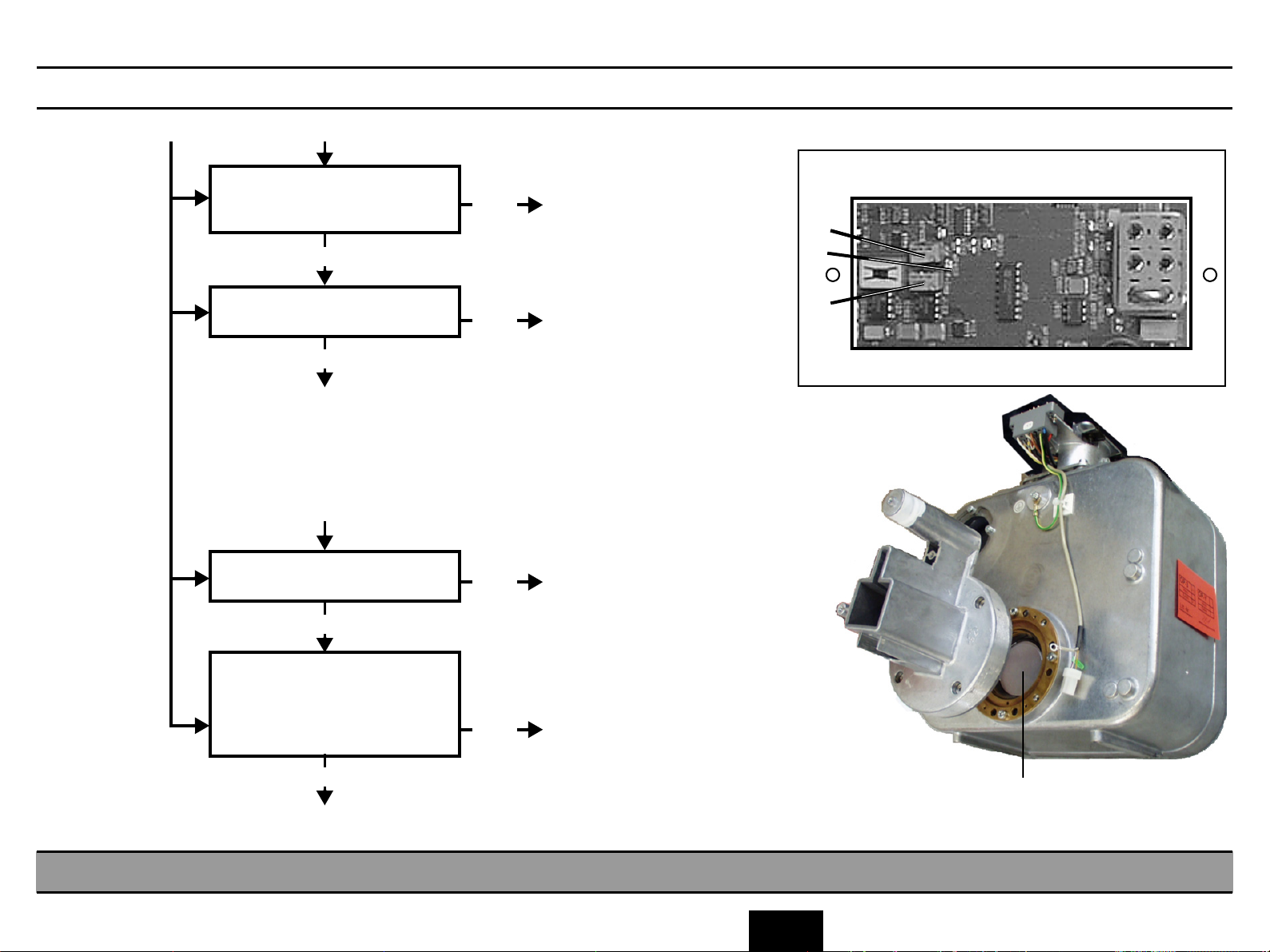
CAUTION: Always switch the unit OFF before connecting a measuring instrument or replacing any components!
Elimination of fault: Help message H3 11
• Swivel the cassette holder out to Ceph position up to the stop.
The Ready LED above the Return key R on the Multitimer continues flashing.
Eliminate the fault with Service Routine S.16, test step 03
See section ”Service Routine S.16”
In test step 03 LED V11 above the patient symbol key on the Multitimer must be lit up.
If this LED is not lit up:
Possible faults 1. Light barrier V5 is not interrupted with the cassette holder swivelled out.
Check and correct switching tab and mechanism.
2. Light barrier V5 (X5 on FH) defective, or disturbance in lead.
Test / repair / replace
3. Fault on board DX1.
Replace board DX1 and perform • 'Adjusting PC board DX1'.
D 3285.077.02.06.02 07.2004
58 35 744 D 3285
LED V11
3.6 Correcting errors of help messages H3 11.
3 - 17
3.6
Page 60

3 - 18
. . . without
coiled cable
Remote control . . .
E1
K10
L11
L9 K2
01
coiled cable
. . . with
K11
L8
Multitimer MT
K10
L12
Control cable for
remote control
E1
01
ON
OFF
L9
O
I
DX1
K2
K2
L8
X10, L3
Shielding plate
Page 61

CAUTION: Always switch the unit OFF before connecting a measuring instrument or replacing any components!
• After power ON, the unit performs a self-adjustment routine.
No key must be pressed on the Multitimer during the self-adjustment!
DX1
MT
Was a key pressed on
no
the Multitimer during
the unit
self-adjustment?
yes
Do not press any key.
Operating error is corrected.
* If a remote control is provided:
Connect the Multitimer to the unit
(connector K2 below the shielding plate).
If the error no longer occurs, check the
cable L9 for short-circuit. With remote control
without coiled cable, also check cable L11.
Check cables for short-circuit (with E1 01) and for
continuity (with E1 02 and E2 03).*
K2
Check cable L3 at K2
for short-circuit -
continuity.
no
Replace L3
Is cable L3 OK?
yes
Check between all
pins on plug K2
K2
Check cable L8 at K2
for short-circuit -
continuity.
no
Replace L8
Is cable L8 OK?
yes
Check between all
pins on plug K2
Multitimer is defective.
Replace
If the error persists:
Replace board DX1
• Perform 'Adjusting board
DX1',
see page 4 - 31
K2
L3
1
2
3
4
5
6
7
Ferrite
Connector X1 at
Multitimer
disconnected
X1.2A
X1.1B
X1.2B
X1.3A
X1.3B
X1.1A
X1.4A
X1.4B
D4
Coiled cable L8
DX1
X10.1
X10.2
X10.3
X10.4
X10.5
X10.6
PK
GY
BK
YE
BN
GN
WH
BU
1
Ferrit
4
5
To open the Multitimer, see
Installation Instructions, section
"Remote control".
L8
K2
D 3285.077.02.06.02 07.2004
58 35 744 D 3285
1
X10
Connector X10
disconnected.
1
L3
3
7
Coiled cable L8
K2
disconnected.
16
K2
PK
GY
YE
BN
GN
WH
BU
5
4
Connector K2
disconnected.
1 6
7
3
3.7 Correcting error of messages E1 01, E1 02, E2 03: Signal paths to control board DX1 are interrupted.
3 - 19
3.7
Page 62

3 - 20
E2
01
Remote control
ON
OFF
K3
Shielding plate
H1.S1
I
O
E2
01
Multitimer MT
Control cable for
remote control
DX1
X4
R
Shielding plate
Page 63

CAUTION: Always switch the unit OFF before connecting a measuring instrument or replacing any components!
• Thermo switch H1.S1 has responded. Wait for it to close ag ain (contact open, check connector K3).
Press the R key on the Multitimer. The error message is no longer displayed.
D 3285.077.02.06.02 07.2004
58 35 744 D 3285
MT
Press the exposure
button.
Is error E2 01 displayed?
yes
Switch the unit OFF
X-ray tube assy
Check switch H1.S1 for
continuity.
Is switch contact closed?
yes
Cable test: check for continuity from
H1.S1 to connector X4 on DX1.
There must be continuity from X4.5 to
X4.6.
Is there continuity?
yes
no
no
no
The unit is OK.
Ω
0 Ω
X-ray tube assembly is overloaded (surface
1.
≥ 65°C), allow to cool down
Check again for continuity at H1.S1.
Unit is OK
2.
Switch H1.S1 is defective; replace.
Locate and repair the cable interruption.
Test
sections
X4.5 to K3.1 (BN); K3.1 (YE) to H1.S1
X4.6 to K3.2 (BK); K3.2 (YE) to H1.S1.
First remove X-ray tube assembly. Disconnect K3.
(1 – 2 hours.)
1 YE 2 YE
H1.S1
On X-ray tube assy
Rear of X-ray tube assembly.
Cover removed
DX1
Shielding plate on side removed
Connector X4 pulled.
Ω
5
6
0 Ω
Replace board DX1.
• Perform 'Adjusting board
DX1',
see page 4 - 31
On rotation ring
8
1BN 2 BK
K3
8
3.8 Correcting error of message E2 01: X-ray tube assembly overheated.
3 - 21
3.8
Page 64
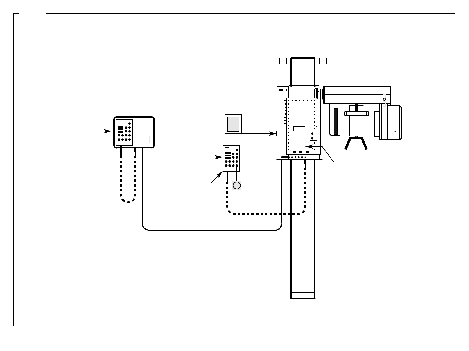
3 - 22
Remote control
E2
04
E2
04
Multitimer MT
Control cable for
remote control
ON
OFF
I
O
J115
DX1
J115
R
Page 65

CAUTION: Always switch the unit OFF before connecting a measuring instrument or replacing any components!
• Zero power range of EEPROM J115 is invalid or destro yed.
DX1
Is error message E2 04 no
longer displayed after
turning the unit off and
on again?
yes
no
The error messages comes on each
time the unit is turned ON.
Replace board DX1
• Perform 'Adjusting board DX1',
see page 4 - 31
D 3285.077.02.06.02 07.2004
58 35 744 D 3285
Press R key on the Multi-
timer.
Unit is OK
3.9 Correcting error of message E2 04: Zero power range has been re-initialized.
3 - 23
3.9
Page 66
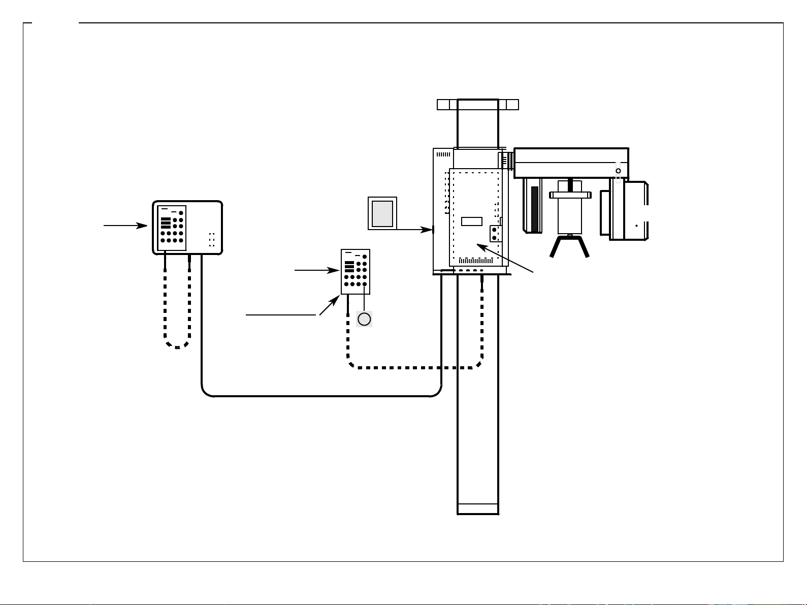
3 - 24
Remote control
E2
11
E2
11
Multitimer MT
Control cable for
remote control
ON
OFF
I
O
X-ray tube assembly
DX1
R
Page 67
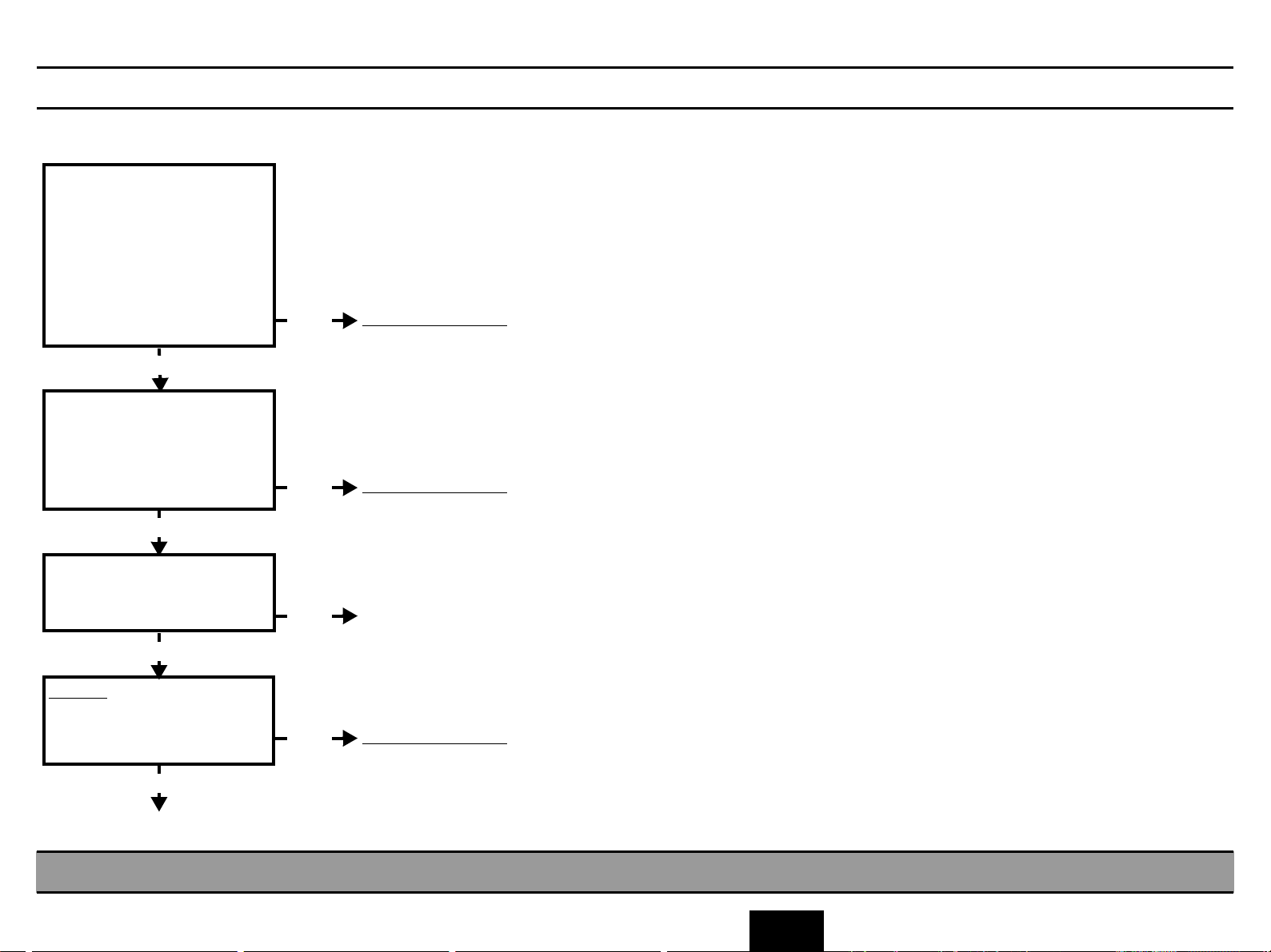
y
CAUTION: Always switch the unit OFF before connecting a measuring instrument or replacing any components!
D 3285.077.02.06.02 07.2004
58 35 744 D 3285
•KV
has been exceeded.
max
Select highest kV value.
Check kV setpoint with
’
'Service routine S.03,'
test step 01.
If out of tolerance
(
incorrect alignment data in E-PROM
Perform automatic setpoint
p
alignment with Service Routine
S.03 test step 04.
Release an exposure. Is error
message repeated?
yes
Filament voltage VH too low.
Perform automatic alignment
with 'Service Routine S.05
test step 02
Release an exposure. Is error
message repeated?
yes
Check basic level heating with
'Service Routine S.05
test step 03
Is signal trace OK?
yes
)
:
no
The unit is OK again.
Perform Service routine S.05,
test step 02.
no
no
The unit is OK again.
Replace the X-ray tube assembly
• 'X-ray tube assembly –
action to be taken . . .,
Replace • Perform 'Adjusting
board DX1',
Release an exposure.
Does the error message re-
see page 4 - 31
no
The unit is OK again.
peat?
yes
Replace the X-ray tube assembly
• 'X-ra
tube assembly – action to be taken . . .,
3.10 Correcting error of message E2 11: Anode voltage too high.
3 - 25
3.10
Page 68

3 - 26
Remote control
E2
12
E2
12
Multitimer MT
Control cable for
remote control
ON
OFF
I
O
X-ray tube assembly
DX1
R
Page 69

CAUTION: Always switch the unit OFF before connecting a measuring instrument or replacing any components!
• Maximum anode current has been exceeded.
MT / DX1
MT
Error indication immediately
1.
after start of radiation.
VH setpoint too high.
'Check with Service routine
S.03, test step 03
Perform Service routine S.03,
test step 04.
Perform Service routine
S.05.2.
MT
Do test steps execute?
yes
S.03
failed
S.05
failed
Replace board DX1.
• 'Adjusting board
DX1',
Replace X-ray tube assembly.
• 'X-ray tube assembly –
action to be taken . . .
Unit is OK.
MT
Error indication during
2.
radiation.
D 3285.077.02.06.02 07.2004
58 35 744 D 3285
see page 4 - 31
',
3.11 Correcting error of message E2 12: Anode current too high.
3 - 27
3.11
Page 70
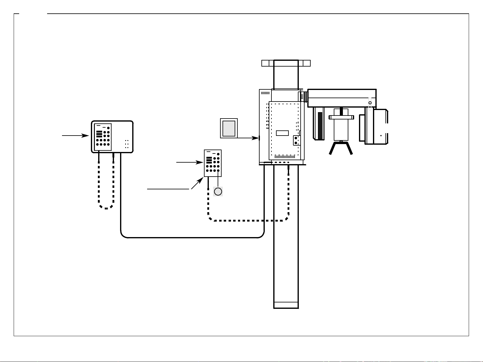
3 - 28
Remote control
E2
13
E2
13
Multitimer MT
Control cable for
remote control
ON
OFF
I
O
R
X-ray tube assembly
Page 71
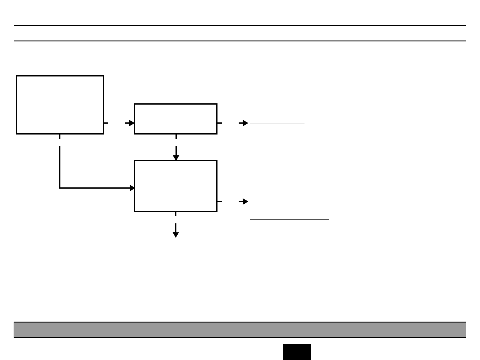
CAUTION: Always switch the unit OFF before connecting a measuring instrument or replacing any components!
D 3285.077.02.06.02 07.2004
58 35 744 D 3285
• Maximum filament voltage VH
• Check if path from X4 on board DX1 to K3 and on to X-ray tube assembly OK.
has been exceeded.
max
Check VH setpoint.
See
Service routine S.03,
test step 03
Is setpoint within specified
tolerance?
yes
no
Perform complete Service
routine S.05.2
Is sepoint within tolerance?
yes
Check actual VH value.
See
Service routine S.04,
test step 03
Is actual value within
tolerance?
yes
Unit is OK.
no
no
Replace board DX1.
• Perform 'Adjusting boar d
DX1', see page 4 - 31
Check if path to X-ray tube
assembly OK
Replace X-ray tube assembly.
Refer to section
• 'X-ray tube assembly
action to be taken . . .
–
',
3.12 Correcting error of message E2 13: Filament voltage too high.
3 - 29
3.12
Page 72
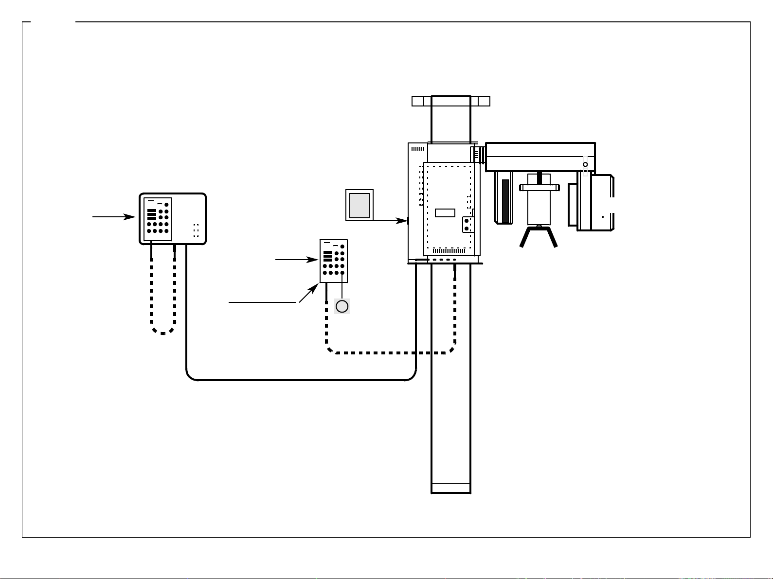
3 - 30
Remote control
E2
14
E2
14
Multitimer MT
Control cable for
remote control
ON
OFF
I
O
R
X-ray tube assembly
Page 73

CAUTION: Always switch the unit OFF before connecting a measuring instrument or replacing any components!
• Bridge short-circuit / transistors overheated.
MT
Acknowledge displayed error:
press the R key.
Wait for about 20 minutes,
allow to cool down.
MT
Adjust for maximum kV
Release an exposure
Is error message repeated?
yes
no
Unit is OK again.
D 3285.077.02.06.02 07.2004
58 35 744 D 3285
Replace board DX1.
See section
• 'Adjusting board DX1',
see page 4 - 31.
3.13 Correcting error of message E2 14: Short-circuit in bridge .
3 - 31
3.13
Page 74

3 - 32
E2
16
Remote control
E2
16
Multitimer MT
Control cable for
remote control
ON
OFF
O
On rotation ring
I
K3
DX1
X4
Shielding plate
On X-ray tube assy
Shielding plate
H1
Page 75

CAUTION: Always switch the unit OFF before connecting a measuring instrument or replacing any components!
• Is connector K3 correctly inserted at the X-ray tube assembly?
• Locate and repair the cable interruption.
Flange unscrewed and
Check continuity of sections
from DX1 X4.1 (RD) to K3.14 on rotation ring,
from K3.14 (WH) to H1.R on X-ray tube assy,
For this purpose remove the X-ray tube assy.
rotated by 180°
D 3285.077.02.06.02 07.2004
58 35 744 D 3285
yes
Is there continuity?
yes
First replace X-ray tube assembly.
Observe section
no
Repair or replace defective cable
• X-ray t ube assembly – action t o be taken . . .,
Second replace board DX1.
• Perform 'Adjusting board DX1', Replace ring lead last.
Connector X4
DX1
unplugged
see page 4 - 31
1
0 Ω
K3
14
8
1
On rotation ring
X-ray head H1,
top view
cover removed.
1
8
14
0 Ω
H1.R
Don’t forget the shielding plates during reassembly
K3
X5
3.14 Correcting error of message E2 16: kV
3 - 33
ACTUAL
– Cable is interrupted.
3.14
Page 76

3 - 34
. . . without
coiled cable
Remote control . . .
K10
L11
L9 K2
E2
20
. . . with
coiled cable
K11
L8
Multitimer MT
K10
L12
L9
Control cable for
remote control
E2
20
D4
ON
OFF
X1
O
I
DX1
R
K2
K2
L8
X10, L3
Shielding plate
Page 77

CAUTION: Always switch the unit OFF before connecting a measuring instrument or replacing any components!
• X-ray room with door contact: Close the door and check proper function of door contact!
MT
Acknowledge error:
Press the R key.
Release
Does E2 20 repeat?
no
The unit is OK.
D 3285.077.02.06.02 07.2004
58 35 744 D 3285
yes
Unit with remote control:
Connect Multitimer directly
to unit.
MT
Acknowledge error:
Press the R key.
Release
Does E2 20 repeat?
yes
Check for correct installa-
tion of connector K2.
If K2 is OK:
Check continuity of L3 from
DX1 X10.3 to K2.4.
Continued on next page
no
Connector K2
(L9) unplugged
6 orange
5 red
4 yellow
1
3 green
7 blue
2 brown
Cable to remote control is interrupted.
Check continuity of L9 from K2.4 (yellow) to K10.3 and
of L12 from K11.4
(yellow) and of L8 to D4 X1.3B.
Connectors K11 (L8)
and K2 (L8) unplugged
6 white
5 green
4 brown
1 pink
7 blue
2 gray
3 yellow
Pull connector X10
Repair / replace the lead
DX1
0 Ω
Ferrit
4
1
1
X10
3
Connector X10
1
unplugged
L3
K2
Coiled cable L8 removed
3.15 Correcting error of message E2 20: Interrupted exposure lead in Multitimer cable.
3 - 35
3.15
Page 78

3 - 36
. . . without
coiled cable
Remote control . . .
K10
L11
L9 K2
E2
20
. . . with
coiled cable
K11
L8
Multitimer MT
K10
L12
L9
Control cable for
remote control
E2
20
D4
ON
OFF
X1
O
I
DX1
R
K2
K2
L8
X10, L3
Shielding plate
Page 79

CAUTION: Always switch the unit OFF before connecting a measuring instrument or replacing any components!
continued
D 3285.077.02.06.02 07.2004
58 35 744 D 3285
If L3 is OK:
Check continuity of L8 from
D4 X1.3B to K2.4.
If L8 is OK:
Replace the Multitimer
MT
Release an exposure.
no
Does E2 20 repeat?
yes
Replace board DX1
• Perform 'Adjusting board DX1',
see page 4 - 31
Unit is OK.
Open Multitimer MT
Pull connector X1
X1
Connector X1
unplugged
3B
0 Ω
Coiled cable L8
Connector K2
unplugged
4
K2
The Multitimer just replaced
is OK.
3.15 Correcting error of message E2 20: Exposure lead in Multitimer cable interrupted.
3 - 37
3.15
Page 80
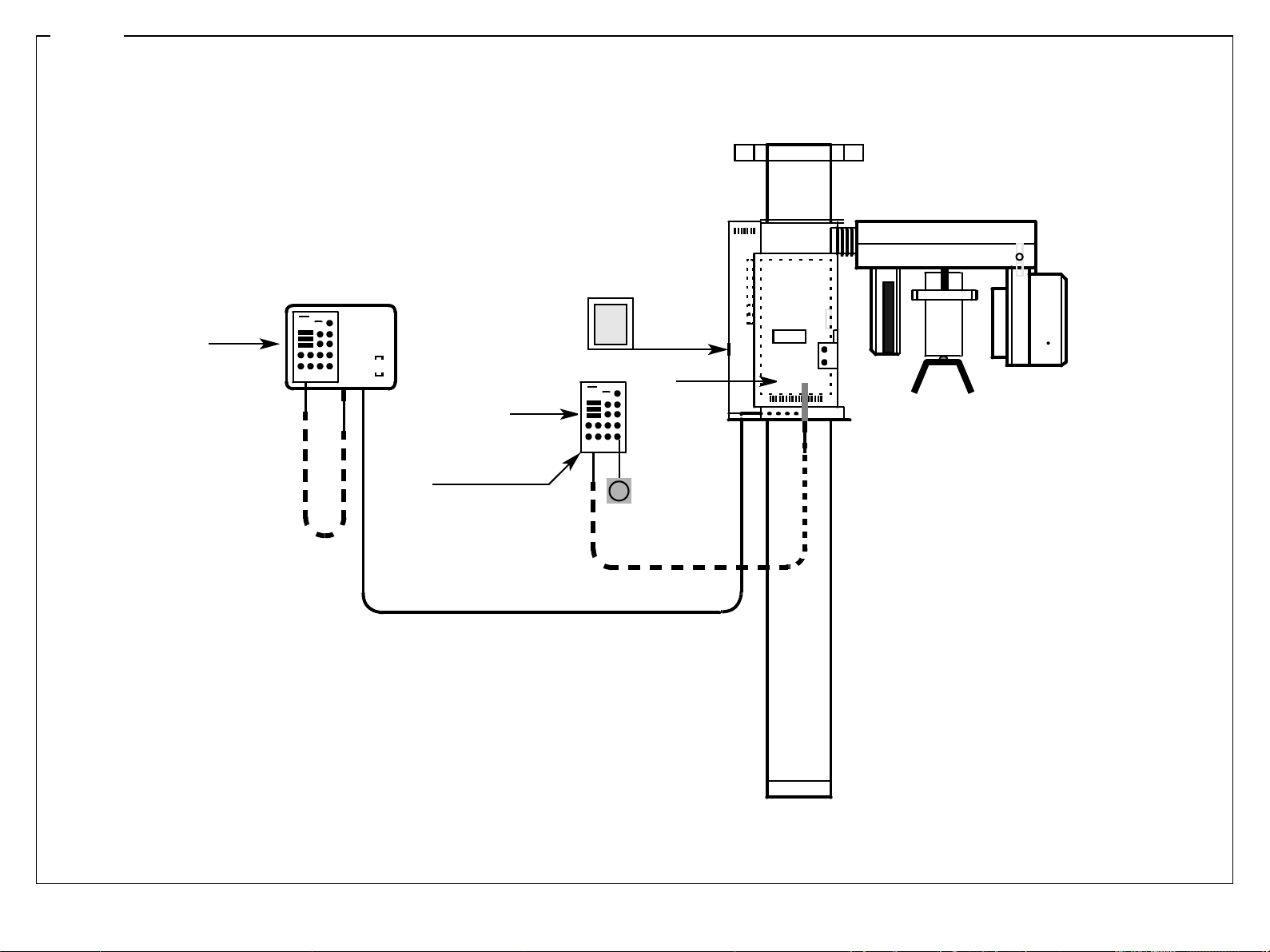
3 - 38
Remote control
E2
40
E2
40
Multitimer MT
Control cable for
remote control
ON
OFF
I
O
DX1
R
Page 81

CAUTION: Always switch the unit OFF before connecting a measuring instrument or replacing any components!
MT / DX1
Check VH setpoint.
See
Service routine S.03,
test step 03
VH setpoint
5.1 - 5.9V
Can VH setpoint be
automatically adjusted by
following
Service routine S.05,
test step 02?
yes
MT
Release an exposure in pro-
gram P1.
Can the exposure be released
without an error message?
yes
no
no
Replace board DX1.
•
Perform 'Adjusting board
DX1',
see page 4 - 31
’Replace the X-ray tube assembly
See section
• X-ray tube assembl y – action to be take n . . .,
D 3285.077.02.06.02 07.2004
58 35 744 D 3285
The unit is OK.
3.16 Correcting error of message E2 40: VH setpoint out of tolerance.
3 - 39
3.16
Page 82

3 - 40
Remote control
E2
43
E2
43
Multitimer MT
Control cable for
remote control
ON
OFF
I
O
DX1
R
Page 83

CAUTION: Always switch the unit OFF before connecting a measuring instrument or replacing any components!
• Fuse on DX3 OK.? Plug connections from L4 OK? LEDs on DX3 lit up?
VH actual value out of
Check basic heating level
with 'Service Routine S.05'
with 'Service Routine S.03'
Can setpoint values be set?
Reset VH actual value.
with 'Service Routine S.05'
Can automatic setpoint
alignment be performed?
tolerance.
test step 03
Are heating pulses
present?
yes
Set setpoint values
test step 04
yes
Set basic heating level
test step 02
yes
no
no
no
Replace board DX1.
•
Perform 'Adjusting board
DX1',
see page 4 - 31
Replace board DX1.
•
Perform 'Adjusting boar d
DX1',
see page 4 - 31
’Replace the X-ray tube assembly
See section
• X-ray tube assembly – action t o be taken . . .,
D 3285.077.02.06.02 07.2004
58 35 744 D 3285
The unit is OK.
3.17 Correcting error of message E2 43: VH setpoint out of tolerance.
3 - 41
3.17
Page 84

3 - 42
Remote control
E2
44
E2
44
Multitimer MT
Control cable for
remote control
ON
OFF
I
O
DX1
R
Page 85

CAUTION: Always switch the unit OFF before connecting a measuring instrument or replacing any components!
• Plug connections from L4 OK?
kV actual value out of
tolerance.
Check kV setpoint value
with 'Service Routine S.03'
Perform kV actual value test,
with 'Service Routine S.04'
test step 01
Is kV setpoint value OK?
yes
test step 01
Is actual value too low?
no
no
Perform setpoint value settings
with 'Service Routine S.03'
test step 04
Is actual value too high?
D 3285.077.02.06.02 07.2004
58 35 744 D 3285
yes
’Replace the X-ray tube assembly
See section
• X-ray tube assembly – action to
be taken . . .,
Replace board DX1.
•
Perform 'Adjusting board
DX1',
yes
see page 4 - 31
3.18 Correcting error of message E2 44: kV setpoint out of tolerance.
3 - 43
3.18
Page 86

3 - 44
Remote control
E2
45
E2
45
Multitimer MT
Control cable for
remote control
ON
OFF
I
O
DX1
R
Page 87

CAUTION: Always switch the unit OFF before connecting a measuring instrument or replacing any components!
mA setpoint out of tolerance
Perform kV actual value test
with 'Service Routine S.03'
Perform heating adjustment
with Service routine S.05,
Does error message repeat?
test step 04.
test step 02.
yes
no
The unit is OK.
D 3285.077.02.06.02 07.2004
58 35 744 D 3285
Check mA setpoint with
Service routine S.04,
test step 02.
mA actual value clearly (>20%)
above setpoint value
(last measured value)?
yes
Replace board DX1.
• Perform 'Adjusting board DX1',
see page 4 - 31
no
Check mA setpoint with
Service routine S.04,
test step 02.
mA actual value clearly (>20%)
under setpoint value
(last measured value)?
yes
Replace X-ray tube assembly
See section
• X-ray tube assembly – action to
be taken . . .,
3.19 Correcting error of message E2 45: mA setpoint out of tolerance.
3 - 45
3.19
Page 88

3 - 46
E3
02
Remote control
E3
02
Multitimer MT
Control cable for
remote control
ON
OFF
O
I
X5
DX1
R
X7
Cover behind
rotation ring
M2
V2
K5, K7
Page 89
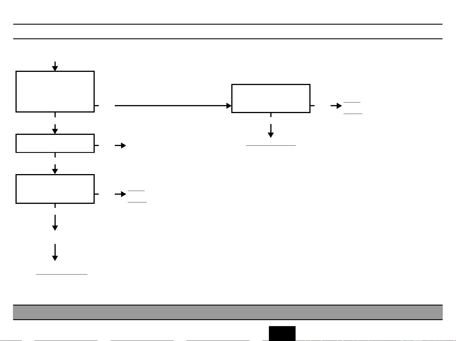
CAUTION: Always switch the unit OFF before connecting a measuring instrument or replacing any components!
• Is seating of plug connectors K5 (M2) and K7 (V2) and of plugs X5 and X7 on board DX1 OK?
• Are supply voltages present on DX1? → LEDs V10-14 on DX3 must light up!
If no errors:
Select Service routine 15, test
step 03.
Is a motor movement
initiated?
yes
no
Check cable L5 from
K5 to X5 (DX1)
for continuity.
OK?
yes
no
Repair
or
replace
D 3285.077.02.06.02 07.2004
58 35 744 D 3285
Is there a visible change of
the LEDs at the Multitimer?
yes
Check cable L5 from
K7 to X7
for continuity.
OK?
yes
Replace light barrier V2.
Does the fault persist:
Replace board DX1
• Perform 'Adjusting board DX1',
see page 4 - 31
no
no
Replace light barrier V2.
Repair
or
replace
Replace board DX1
• Perform ' Adjusting boa rd
DX1’,
see page 4 - 31
or
replace actuator M2
Repair chapter,
see page 6 - 9.
3.20 Correcting error of messages E3 01, E3 02:
3 - 47
Actuator M2 has not left/reached the tripping position.
3.20
Page 90

3 - 48
R
E3
05
Remote control
E3
05
Multitimer MT
Control cable for
remote control
ON
OFF
O
I
R
DX1
X6
M3
V3
Tension
spring
Cassette carriage
FH, X1, X2, X3
Page 91
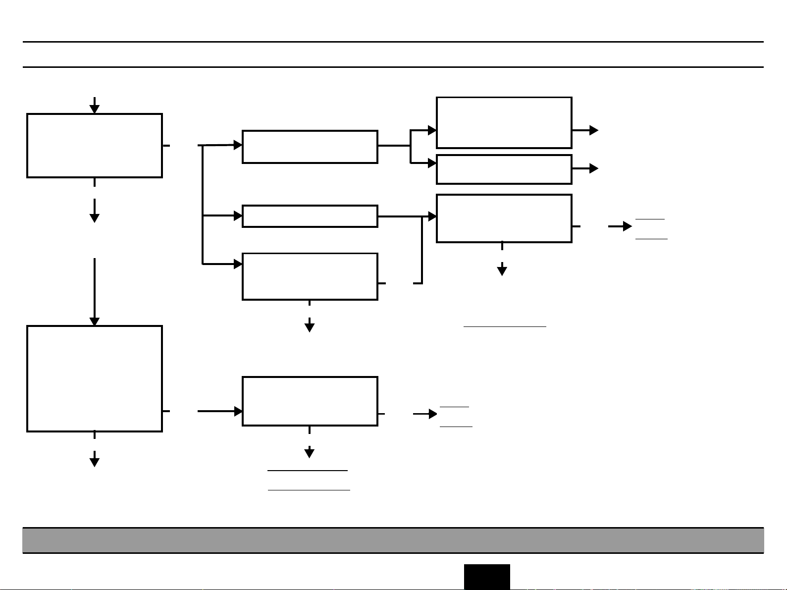
CAUTION: Always switch the unit OFF before connecting a measuring instrument or replacing any components!
• Cassette holder must be set for Pan mode, service routine m ust not be selected, no help message or error message must be displayed.
Pulley for rope drive is
Move the cassette by hand off
the reference point.
Does the cassette return to
the reference point and is
E3 05 displayed?
yes
The signal ’Cassette at
reference point’ is not
detected.
Select Service routine S.16,
test step 03.
Move cassette to Pan
position, LED3 lights up.
Swap connector X4 and X3
on DX8.
Does LED3 light up when
positioning the cassette?
yes
no
no
Motor runs, but cassette does
not move.
Motor does not run.
Motor jerks.
Is drive mechanically ob-
structed?
yes
Remove mechanical
obstruction.
Check cables L4 and L14/L15
(if present) for continuity.
OK?
yes
no
no
loose, rope slipped
from pulley or spring not
engaged.
Rope is damaged or
ruptured
Check cables L4 and L14/L15
(if present) for continuity.
OK?
yes
Replace board FH,
or film motor M3
or
replace board DX1
• Perform 'Adju sting board
DX1',
see page 4 - 31
Repair
or
replace
Repair rope drive
Replace rope, see section
’Repairs’
Repair
no
or
replace
D 3285.077.02.06.02 07.2004
58 35 744 D 3285
Replace board FH,
Replace light barrier V3.
Reinsert connector X4 in its
socket.
replace board DX1
• Perform 'Adjusting board DX1',
or
see page 4 - 31
3.21 Correcting error of messages E3 05, E3 06:
3 - 49
Cassette carriage has not left/reached the reference point.
3.21
Page 92

3 - 50
Remote control
E3
12
E3
12
Multitimer MT
Control cable for
remote control
ON
OFF
I
O
DX1
↑ ↓
R
Page 93

CAUTION: Always switch the unit OFF before connecting a measuring instrument or replacing any components!
• Height adjustment keys must not be pressed during self-adjustment of the unit!
D 3285.077.02.06.02 07.2004
58 35 744 D 3285
Was a HV key pressed during
self-adjustment?
yes
Acknowledge the error with
the R key.
The unit is OK.
no
Unplug connector X8 on
board DX1.
Is the error message E3 12
repeated?
yes
Replace board DX1
• Perform 'Adjusting board
DX1', see page 4 - 31
no
Check cable L7
for short-circuit.
OK?
yes
Height adjustment keys
defect
replace
no
Repair
or
replace
3.22 Correcting error of message E3 12:
3 - 51
Key for height adjustment pressed during unit self-adjustment.
3.22
Page 94

3 - 52
Tension bolt
for belt
Top view
Belt pulley
Coupling
Rubber coating
on inside
Remote control
E3
32
Multitimer MT
ON
OFF
O
M1/K4 behind rotation ring
V1/V7 in rotation ring,
K6/K8 behind rotation ring
L4
Rotation ring
I
X5
DX1
R
X7
X-ray head
Motor M1
Counterbalancing
pulley
Control cable for
remote control
Page 95

CAUTION: Always switch the unit OFF before connecting a measuring instrument or replacing any components!
• Check rotation ring for possible mechanical faults: move the X-ray tube assy by hand over the entire rotation range. X-ray tube assy must move smoot hly without grinding noise
• Possible faults: weight compensation disk on motor M1, rooting of cable L4 in rotation ring, cable ties, covers.
• Possible electrical faults: connectors X5 and X7 on DX1 must be properly inserted
• Do supply voltages reach DX1? → LEDs V10-14 on DX3 must light up!
D 3285.077.02.06.02 07.2004
58 35 744 D 3285
Move the X-ray tube assembly by
hand to its end position.
Press the R key on the Multitimer.
Drive motor jerks, error
message E3 33 appears
after about 16 sec.
Drive motor does not run,
E3 33 appears after about
16 sec.
Move the X-ray tube
assembly by hand to its start
position. Unplug K6.
Press the T key on
the Multitimer.
Motor M1 runs and error mes-
sage E3 32 appears?
yes
no
Are contacts K4 and X5.1 - 4
OK?
yes
Check cable L5 for
continuity.
OK?
yes
Check the winding resistors
with a multimeter.
Is resistance 5 Ω ± 15 %?
yes
Check connection between
winding and motor housing
with continuity tester.
Does connection exist?
yes
no
no
no
no
Repair contact problem
Repair
or
replace
Motor M1 defective.
Replace, see page 6 - 5
Replace board DX1
• Perform
'Adjusting board DX1',
see page 4 - 31
Motor M1 defective. Replace,
see page 6 - 5
Continued on next page
Light barrier V1 defective.
Replace.
3.23 Correcting error of messages E3 32, E3 33: Start position for rotation was not exited/reached.
3 - 53
3.23
Page 96

3 - 54
Tension bolt
for belt
Top view
Rubber coating
on inside
M1/K4 behind rotation ring
V1/V7 in rotation ring,
K6/K8 behind rotation ring
L4
Rotation ring
Belt pulley
Coupling
Motor M1
Counterbalancing
pulley
Remote control
E3
32
Multitimer MT
Control cable for
remote control
ON
OFF
O
I
X5
DX1
R
X7
X-ray head
Page 97

CAUTION: Always switch the unit OFF before connecting a measuring instrument or replacing any components!
continued
Replace light barrier V1.
X-ray tube assembly collides with rotation start position, error message E3
32 appears after app 16 s.
Is holding bracket of light
barrier V1 maladjusted or
bent?
no
Press the T key on
the Multitimer.
Does the error message
repeat?
no Light barrier V1 defective
D 3285.077.02.06.02 07.2004
58 35 744 D 3285
yes
Adjust light barrier V1 or replace light barrier with hold-
ing bracket.
yes
Replace board DX1
• Perform 'Adjusting board DX1',
see page 4 - 31
3.23 Correcting error of messages E3 32, E3 33: Start position for rotation was not exited/reached.
3 - 55
3.23
Page 98
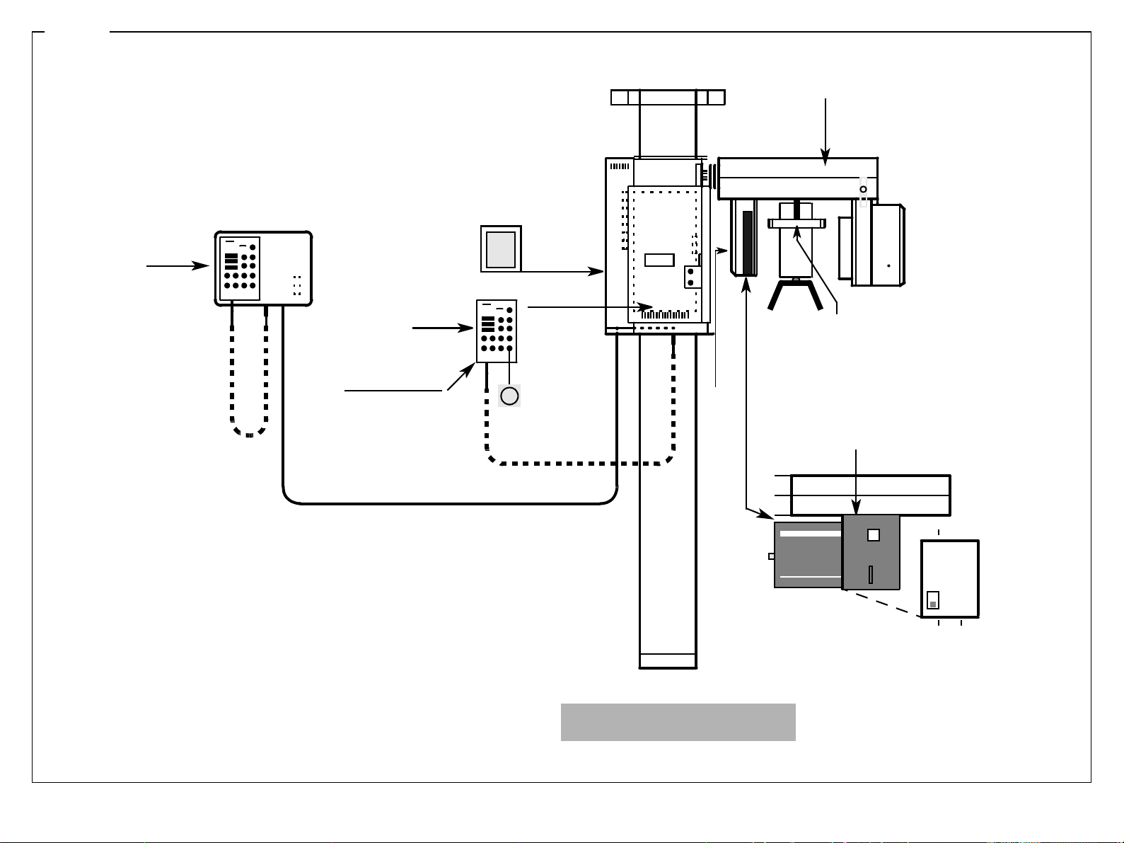
3 - 56
Remote control
M2
Behind rotation ring
E3
36
E3
36
Multitimer MT
Control cable for
remote control
ON
OFF
O
I
DX1
Forehead support
FH
M3, V3, V4, V5
R
Cassette holder
V4, X4
Cover removed,
plug disconnected
ORTHOPHOS 3
Page 99

CAUTION: Always switch the unit OFF before connecting a measuring instrument or replacing any components!
• Body parts or clothing, bandages and the like must not interfere with unit functions.
Start test run with the T key. During the mo vement the cassette holder m ust not come into contact with the patient.
Does retaining spring still have sufficient mech anical tension?
D 3285.077.02.06.02 07.2004
58 35 744 D 3285
Fully open the forehead support, select test run on the
Multitimer and release an
exposure.
The error message is no
longer displayed.
The cassette holder strikes
the forehead support and tilts
out of the Pan position.
The error message is displayed intermittently.
The cassette holder strikes
the patient. Unit is OK.
Is the forehead support incor-
rectly installed or bent?
yes
Correctly instal the forehead
support or replace it, if dam-
aged.
Is the light barrier V4 correctly
adjusted?
yes
no
no
Actuator movement is not OK.
Check actuator movement with
Service routine S.15,
see page 5 - 41.
Adjust light barrier V4.
3.24 Correcting error of message E3 36:
3 - 57
Replace light barrier V4.
Does the message repeat?
yes
no
Light barrier V4 defective.
Continued on next page
Cassette holder was swivelled from the Pan position during Pan exposure.
3.24
Page 100
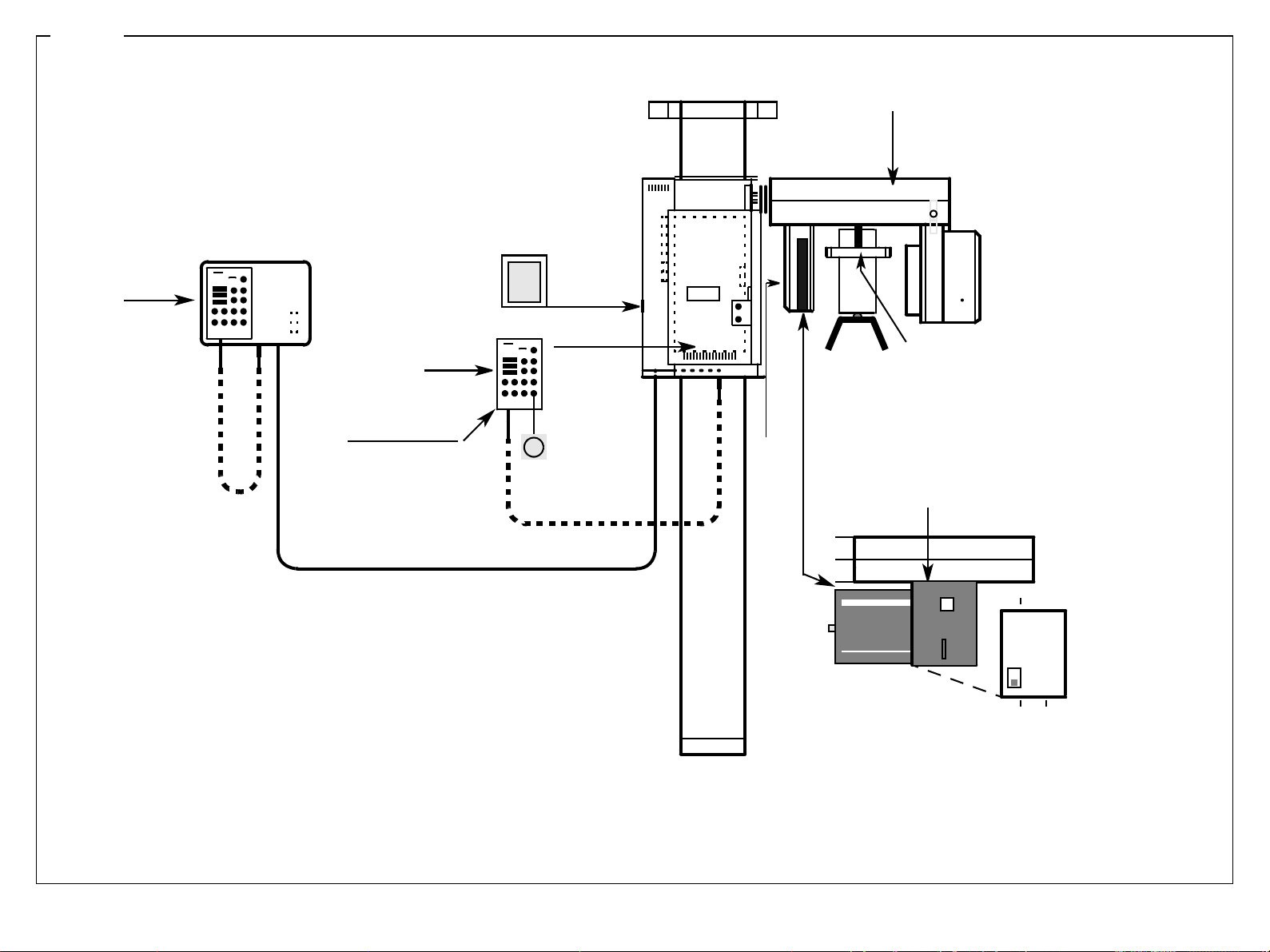
3 - 58
Remote control
M2
Behind rotation ring
E3
36
E3
36
Multitimer MT
Control cable for
remote control
ON
OFF
O
I
DX1
Forehead support
FH
M3, V3, V4, V5
R
Cassette holder
V4, X4
Cover removed,
plug disconnected
 Loading...