

Page 1

kÉï=~ë=çÑW=
15096.1.Rev.001
MQKOMNO
pбкзе~=aЙен~д=`^aL`^j=pулнЙг
беi~Д=j`=ui
lйЙк~нбеЦ=fелнкмЕнбзел
bеЦдблЬ=ErpF
Operating Instructions
Page 2

Sirona Dental Systems GmbH
15096.1.Rev.001
Operating Instructions Sirona Dental CAD/CAM System
Contents
1
2
3
4
Dear Customer, ........................................................................................................ 5
General information.................................................................................................. 6
2.1 Identification of the danger levels.................................................................. 6
2.2 Formats and symbols used ........................................................................... 7
2.3 Warranty........................................................................................................ 7
General description .................................................................................................. 8
3.1 Certification ................................................................................................... 8
3.2 Intended use ................................................................................................. 9
3.3 Further use of Sirona Dental CAD/CAM System .......................................... 10
Safety ....................................................................................................................... 11
4.1 Basic safety information ................................................................................ 11
4.1.1 Prerequisites ...................................................................................... 11
4.1.2 Maintenance and repair ..................................................................... 11
4.1.3 Changes to the product...................................................................... 11
4.1.4 Accessories........................................................................................ 12
4.2 Milling chamber door open during the milling operation................................ 12
4.3 Wireless phone interference with equipment ................................................ 12
5
Installation and startup ............................................................................................. 13
5.1 Transport and unpacking .............................................................................. 13
5.2 Disposal of packaging materials ................................................................... 13
5.3 Installation site .............................................................................................. 14
5.3.1 Installation site with low light incidence.............................................. 14
5.4 Initial startup.................................................................................................. 14
5.4.1 Functional elements........................................................................... 15
5.4.2 Display description............................................................................. 17
5.4.3 Lighting of the milling chamber .......................................................... 17
5.4.4 Inserting the milling chamber sieve.................................................... 18
5.4.5 Connecting the barcode reader.......................................................... 18
5.4.6 Installation.......................................................................................... 19
5.4.6.1 Connecting to the PC via LAN ......................................................... 19
5.4.6.2 Connecting the milling unit to the power supply............................... 19
2 D 3439.201.01.18.23 04.2012
63 33 590 D 3439
Page 3

Sirona Dental Systems GmbH
15096.1.Rev.001
Operating Instructions Sirona Dental CAD/CAM System
5.4.6.3 Installing the unit ............................................................................. 19
5.4.7 Filling the water tank ......................................................................... 21
5.4.8 Switching the unit ON and OFF ........................................................ 22
5.5 Repacking .................................................................................................... 23
5.6 Scope of supply............................................................................................ 23
5.7 Storage......................................................................................................... 23
6
Operation................................................................................................................. 24
6.1 Configuration (inLab MC XL)........................................................................ 24
6.2 Calibrating the unit ....................................................................................... 25
6.3 Starting the milling process .......................................................................... 28
6.4 Entering the bar code ................................................................................... 30
6.5 Using the manual block fixing....................................................................... 31
7
Maintenance............................................................................................................ 33
7.1 Changing the water ...................................................................................... 34
7.1.1 General information........................................................................... 34
7.1.2 Changing the water ........................................................................... 35
7.2 Milling instruments........................................................................................ 37
7.2.1 Overview of materials and milling instruments.................................. 37
7.2.2 Changing milling instruments (burs).................................................. 38
7.3 Care and cleaning agents ............................................................................ 40
7.4 Cleaning surfaces......................................................................................... 41
7.4.1 Disinfecting........................................................................................ 41
7.4.2 Protection against medicaments ....................................................... 41
7.4.3 Cleaning ............................................................................................ 41
7.5 Replacing the main fuses ............................................................................. 42
7.6 Changing the filter ........................................................................................ 43
7.6.1 Changing filters on the external tank................................................. 44
7.7 Removing water from the unit ...................................................................... 47
7.8 Using the tank cap opener ........................................................................... 48
8
Technical description............................................................................................... 50
8.1 System requirements ................................................................................... 50
8.2 milling unit .................................................................................................... 50
8.2.1 General technical description............................................................ 50
63 33 590 D 3439
D 3439.201.01.18.23 04.2012
3
Page 4

Sirona Dental Systems GmbH
15096.1.Rev.001
Operating Instructions Sirona Dental CAD/CAM System
8.2.2 Technical data.................................................................................... 51
8.2.3 Controller board ................................................................................. 51
9
Disposal.................................................................................................................... 52
Index......................................................................................................................... 53
4 D 3439.201.01.18.23 04.2012
63 33 590 D 3439
Page 5

Sirona Dental Systems GmbH 1 Dear Customer,
15096.1.Rev.001
Operating Instructions Sirona Dental CAD/CAM System
Dear Customer,
1
General description
Dear Customer,
Thank you for purchasing your inLab MC XL® from Sirona.
This device enables you to produce dental restorations, e.g. from ceramic
material with a natural appearance (CEramic REConstruction).
Improper use and handling can create hazards and cause damage.
Please read and follow these operating instructions carefully and always
keep them within easy reach.
To prevent personal injury or material damage, it is important to observe
all safety information.
To safeguard your warranty claims, please complete the attached
Installation Report / Warranty Passport when the system is handed over
and send it to the indicated fax number.
Your Team
Your
inLab MC XL Team
63 33 590 D 3439
D 3439.201.01.18.23 04.2012
5
Page 6
2 General information Sirona Dental Systems GmbH
15096.1.Rev.001
2.1 Identification of the danger levels Operating Instructions Sirona Dental CAD/CAM System
General information
2
General information
Please read this document completely and follow the instructions exactly.
You should always keep it within reach.
Original language of the present document: German.
2.1
Identification of the danger levels
Identification of the danger lev els
To prevent personal injury and material damage, please observe the
warning and safety information provided in this document. Such
information is highlighted as follows:
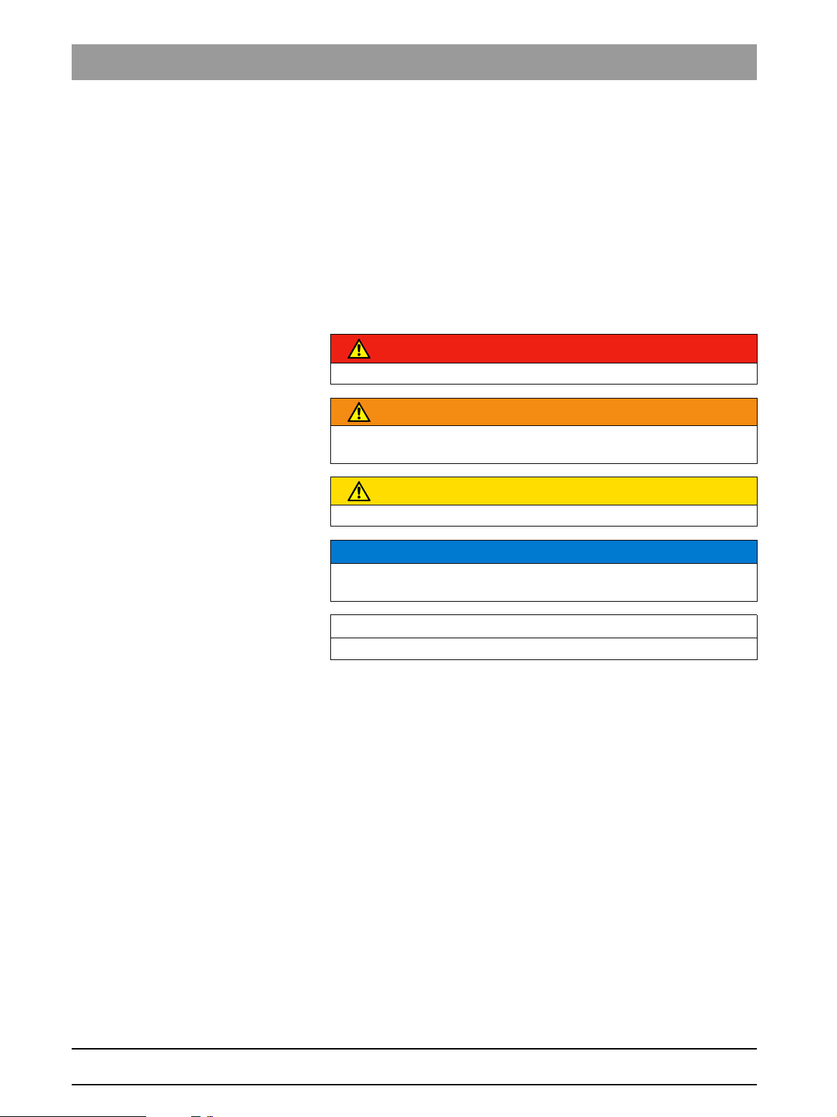
DANGER
An imminent danger that could result in serious bodily injury or death.
WARNING
A possibly dangerous situation that could result in serious bodily injury
or death.
CAUTION
A possibly dangerous situation that could result in slight bodily injury.
NOTICE
A possibly harmful situation which could lead to damage of the product
or an object in its environment.
IMPORTANT
Application instructions and other important information.
Tip: Information on making work easier.
63 33 590 D 3439
6 D 3439.201.01.18.23 04.2012
Page 7
Sirona Dental Systems GmbH 2 General information
15096.1.Rev.001
Operating Instructions Sirona Dental CAD/CAM System
2.2
2.3
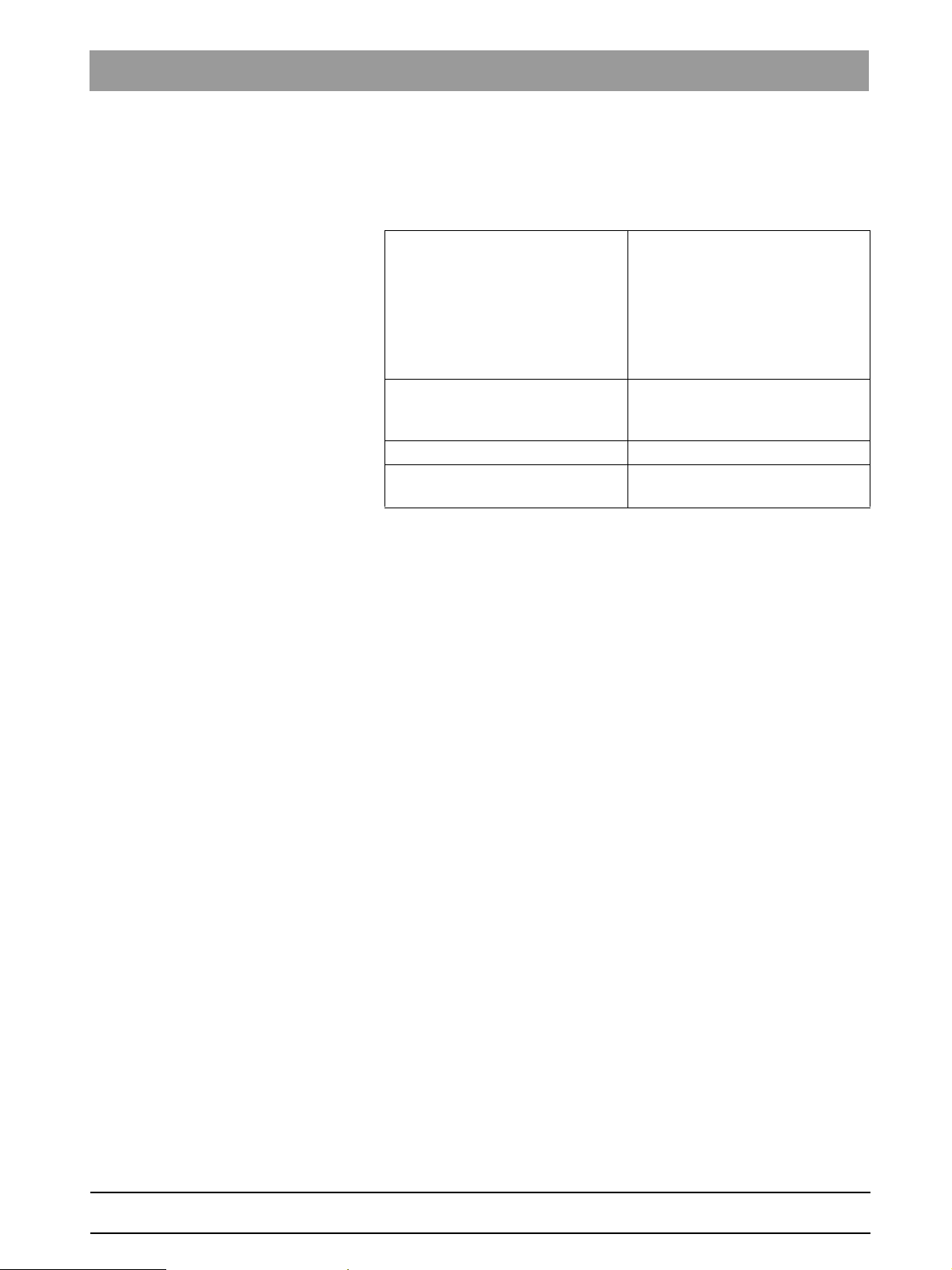
Formats and symbols used
Formats and symbols used
The formats and symbols used in this document have the following
meaning:
✔ Prerequisite
1. First action step
2. Second action step
or
➢ Alternative action
Result
See "Formats and symbols
used [ → 7]“
● List Designates a list.
"Command/menu item" Identifies commands, menu items
Prompts you to do something.
Identifies a reference to another
te x t passag e and spec i fies its p age
number.
or quotations.
Warranty
Warranty
To safeguard your warranty claims, please complete the attached
Installation Report / Warranty Passport when the unit is handed over.
Then fax it to the specified fax no.
63 33 590 D 3439
D 3439.201.01.18.23 04.2012
7
Page 8
3 General description Sirona Dental Systems GmbH
24
15096.1.Rev.001
3.1 Certification Operating Instructions Sirona Dental CAD/CAM System
General description
3
General description
3.1
Certification
Certification
CE mark
This product bears the CE mark in accordance with the provisions of
directives 2006/95/EC (Low Voltage Directive) and 2004/108/EC (EMC
Directive).
CAUTION
CE mark for connected products
Further products which are connected to this unit must also bear the CE
mark. These products must be tested according to the applicable
standards.
Examples EN 60601 + EN 60950 + UL 60950
Examples of CE mark for connected products:
● EN 60601-1:1990 + A1:1993 +A2:1995 based on IEC 60601-1
● EN 60950:1992 + A1: 1993 + A2: 1993 + A3: 1995 + A4: 1997 based
on IEC 60950
● UL 60950 third edition 2000
GOST mark
8 D 3439.201.01.18.23 04.2012
63 33 590 D 3439
Page 9
Sirona Dental Systems GmbH 3 General description
15096.1.Rev.001
Operating Instructions Sirona Dental CAD/CAM System
3.2
Intended use
Indications for use
Intended use
The Sirona Dental CAD/CAM System is intended for use in partially or
fully edentulous mandibles and maxillae in support of single or multipleunit cement retained restorations. For the titanium bases SSO 3.5 L and
SBL 3.3 L the indication is restricted for replacement of single lateral
incisors in the maxilla and lateral and central incisors in the mandible. The
system consists of three major parts: TiBase, inCoris mesostructure, and
CAD/CAM software. Specifically, the inCoris mesostructure and TiBase
components make up a two-piece abutment which is used in conjunction
with endosseous dental implants to restore the function and aesthetics in
the oral cavity. The inCoris mesostructure may also be used in
conjunction with the Camlog Titanium base CAD/CAM (types
K2244.xxxx) (K083496) in the Camlog Implant System. The CAD/CAM
software is intended to design and fabricate the inCoris mesostructure.
The inCoris mesostructure and TiBase two-piece abutment is compatible
with the following implants systems:
● Nobel Biocare Replace (K020646)
● Nobel Biocare Branemark (K022562)
● Friadent Xive (K013867)
● Biomet 3i Osseotite (K980549)
● Astra Tech Osseospeed (K091239)
● Zimmer Tapered Screw-Vent (K061410)
● Straumann SynOcta (K061176)
● Straumann Bone Level (K053088, K062129, K060958)
● Biomet 3i Certain (K014235, K061629)
● Nobel Biocare Active (K071370)
CAUTION
Small diameter implants and large angled abutments in the anterior
region of the mouth due to possible failure of the implant system.
CAUTION
Federal Law (USA) restricts sale of this device to or on the order of a
physician, dentist, or licensed practitioner.
63 33 590 D 3439
D 3439.201.01.18.23 04.2012
9
Page 10

3 General description Sirona Dental Systems GmbH
15096.1.Rev.001
3.3 Further use of Sirona Dental CAD/CAM System Operating Instructions Sirona Dental CAD/CAM System
3.3
Further use of Sirona Dental CAD/CAM System
Further use of Sirona De ntal CAD/CAM Sy stem
The Sirona Dental CAD/CAM System is also:
● an optical impression system for computer assisted design and
manufacturing (CAD/CAM) according to 21 CFR 872.3661. The
system records the topographical characteristics of teeth, dental
impressions, or stone models for use in the computer-assisted design
and manufacturing of dental restorative prosthetic devices.
● an endosseous dental implant accessory according to 21 CFR
872.3980. The system is used to produce a part that the user can
manually incorporate together with other 3rd party components into a
dental surgery guide, a temporary accessory used with endosseous
dental implants with tissue contact for less than 1 hour (exempt).
Such devices are exempt from the premarket notification procedures.
10 D 3439.201.01.18.23 04.2012
63 33 590 D 3439
Page 11
Sirona Dental Systems GmbH 4 Safety
15096.1.Rev.001
Operating Instructions Sirona Dental CAD/CAM System
Safety
4
Safety
4.1
Basic safety information
Basic safety information
4.1.1 Prerequisites
Prerequisites
NOTICE
Important information on the building installation
The building installation must be performed by a qualified expert in
compliance with the national regulations. DIN VDE 0100-710 applies in
Germany.
NOTICE
Restrictions regarding installation site
The system is not intended for operation in areas subject to explosion
hazards.
NOTICE
Do not damage the unit!
The unit can be damaged if opened improperly.
It is expressly prohibited to open the unit with tools!
4.1.2 Maintenance and repair
Maintenance and repair
As manufacturers of dental instruments and laboratory equipment, we
can assume responsibility for the safety properties of the unit only if the
following points are observed:
63 33 590 D 3439
D 3439.201.01.18.23 04.2012
● The maintenance and repair of this unit may be performed only by
Sirona or by agencies authorized by Sirona.
● Components which have failed and influence the safety of the unit
must be replaced with original (OEM) spare parts.
Please request a certificate whenever you have such work performed. It
should include:
● The type and scope of work.
● Any changes made in the rated parameters or working range.
● Date, name of company and signature.
4.1.3 Changes to the product
Changes to the product
Modifications to this unit which may affect the safety of the operator,
patients or third parties are prohibited by law!
11
Page 12
4 Safety Sirona Dental Systems GmbH
15096.1.Rev.001
4.2 Milling chamber door open during the milling operation Operating Instructions Sirona Dental CAD/CAM System
4.1.4 Accessories
Accessories
In order to ensure product safety, this product may be operated only with
original Sirona accessories or third-party accessories expressly approved
by Sirona. The user assumes the risk of using non-approved accessories.
4.2
4.3
Milling chamber door open during the milling operation
Milling chamber door open during the milling operation
CAUTION
Milling instruments that continue to run
When the milling chamber door is opened during the milling operation,
the milling instruments could continue to run for a short time.
➢ Be careful not to touch the milling instruments with your hand or any
other object during this time.
➢ Avoid opening the milling chamber door while the milling unit is in
operation.
➢ Before you open the milling chamber door, end any actions that are
"Stop"
running by selecting the
application software.
key on the milling unit or in the
Wireless phone interference with equipment
Wireless phone interference with equipment
The use of mobile wireless phones in practice or hospital environments
must be prohibited to ensure safe operation of the unit.
12 D 3439.201.01.18.23 04.2012
63 33 590 D 3439
Page 13
Sirona Dental Systems GmbH 5 Installation and startup
15096.1.Rev.001
Operating Instructions Sirona Dental CAD/CAM System
Installation and startup
5
Installation and startup
5.1
Transport and unpacking
Transport and unpacking
Transport and unpacking
All Sirona products are carefully checked prior to shipment. Please
perform an incoming inspection immediately after delivery.
1. Check the delivery note to ensure that the consignment is complete.
2. Check whether the product shows any visible signs of damage.
NOTICE
Damage during transport
If the product was damaged during transport, please contact your
carrying agent.
If return shipment is required, please use the original packaging for
shipment.
Before every transport, the unit must be drained prior to shipment (if it has
been operated). See "Removing water from the unit" [ → 47]
Transport without packaging
CAUTION
Damage to the unit or danger of injury during transport without
packaging
5.2
There is a danger of the unit falling down if it is grasped by its plastic
housing.
➢ The unit should always be carried by two persons.
➢ Do not grasp the unit by its plastic housing.
➢ Always grasp the unit by its chassis next to its feet.
Disposal of packaging materials
Disposal of packaging materials
The packaging must be disposed of in compliance with the relevant
national regulations. Please observe the regulations applicable in your
country.
63 33 590 D 3439
D 3439.201.01.18.23 04.2012
13
Page 14
5 Installation and startup Sirona Dental Systems GmbH
15096.1.Rev.001
5.3 Installation site Operating Instructions Sirona Dental CAD/CAM System
5.3
Installation site
Installation site
CAUTION
Install out of the reach of patients!
Do not install or operate the milling unit in the vicinity of the patient
(place it at least 1.5 m away from the patient).
The milling unit requires a level floor space of approx. 700 x 420 mm The
height of the milling unit is:
● with the milling chamber door closed: 425 mm
● with the milling chamber door open: 570mm
Install the milling unit in such a way that it is not difficult to operate the
main switch.
Make sure that the ventilation slots underneath and at the back of the unit
remain unobstructed. The distance between the rear side of the unit and
the room wall must be at least 10 cm.
Note that the unit weighs 43 kg!
The unit must not be installed at sites with a high level of humidity or dust!
NOTICE
Installation in a cabinet
If the unit is installed in a cabinet, you must provide for adequate heat
exchange.
The ambient temperature surrounding the unit must be between 5°C
and 40°C.
5.3.1 Installation site with low light incidence
Impairment of the scanned result
Installation site with low light incidence
NOTICE
Impairment of the scanned result due to sudden incidence of light.
A sudden, strong incidence of light may falsify the scanned result.
Set the unit up so that the milling chamber is not located directly in the
beam path of an extreme light source and is not exposed to direct
sunlight.
5.4
Initial startup
Initial startup
NOTICE
Important information on initial startup
Observe the software installation instructions!
14 D 3439.201.01.18.23 04.2012
63 33 590 D 3439
Page 15
Sirona Dental Systems GmbH 5 Installation and startup
ABC
D
E
E
F
15096.1.Rev.001
Operating Instructions Sirona Dental CAD/CAM System
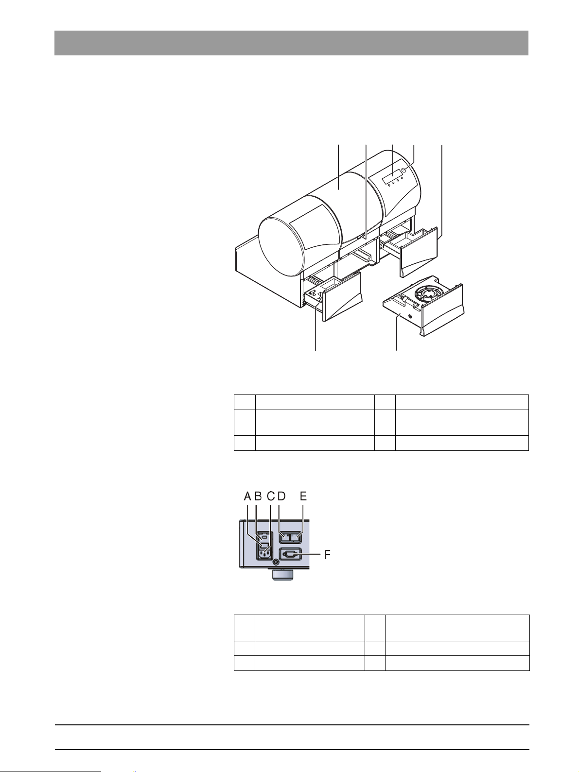
5.4.1 Functional elements
Functional elements
Unit overview
Overview of the milling unit
A Milling chamber D ON/OFF switch
B Milling chamber
EDrawer
door catch
C Display F Water tank
Ports on the back side
Ports on the back side
Ports
A Main switch
I = ON, 0 = OFF
D LAN port
Ethernet
B Fuse cover E This connection is not used
C Power connection F Barcode reader port
63 33 590 D 3439
D 3439.201.01.18.23 04.2012
15
Page 16
5 Installation and startup Sirona Dental Systems GmbH
C
A
C
A
B
D E
15096.1.Rev.001
5.4 Initial startup Operating Instructions Sirona Dental CAD/CAM System
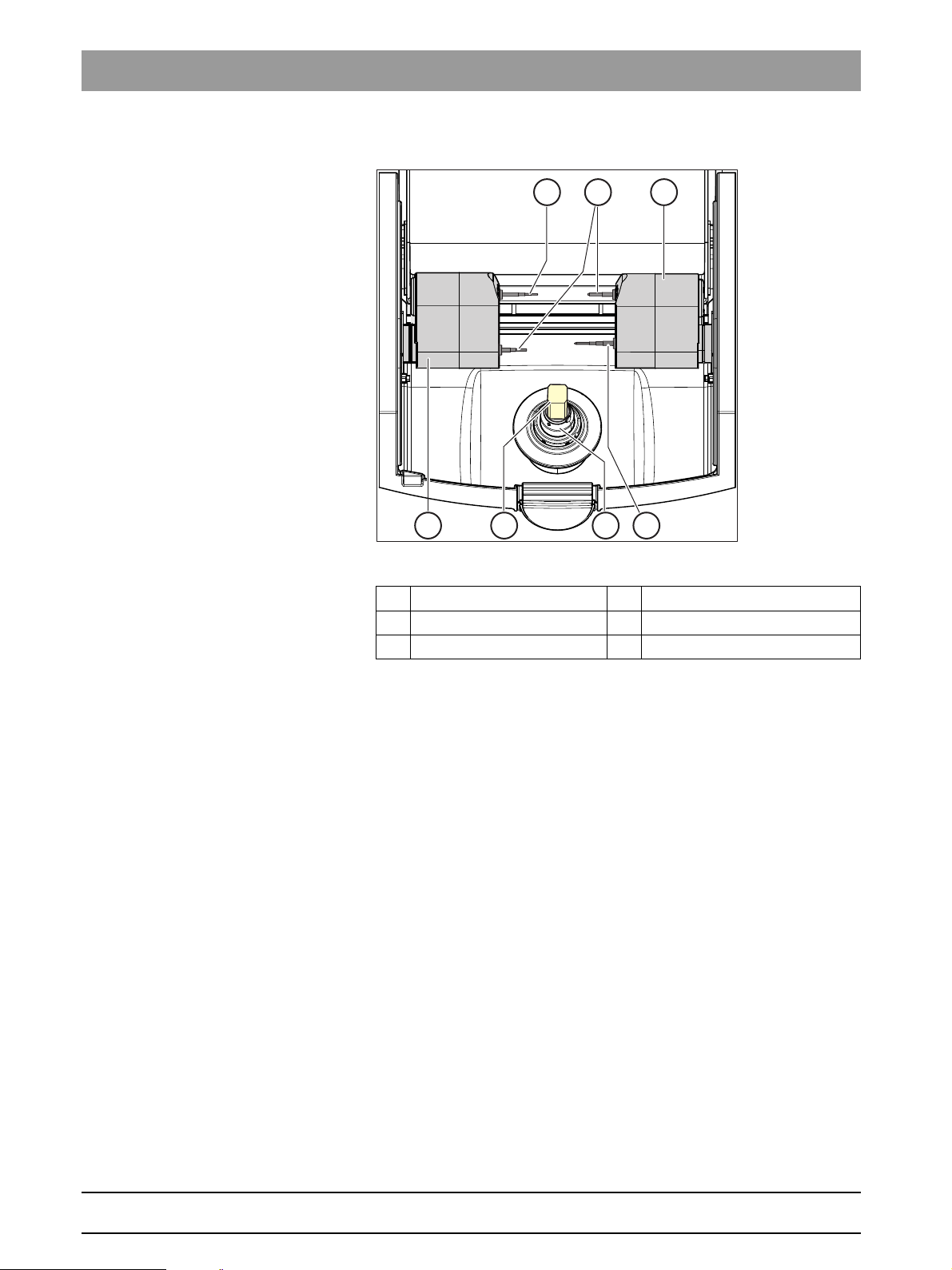
Milling chamber
Milling chamber
A Bur set 1 D Ceramic block
B Bur set 2 E Workpiece spindle
C Motor mount
16 D 3439.201.01.18.23 04.2012
63 33 590 D 3439
Page 17
Sirona Dental Systems GmbH 5 Installation and startup
15096.1.Rev.001
Operating Instructions Sirona Dental CAD/CAM System
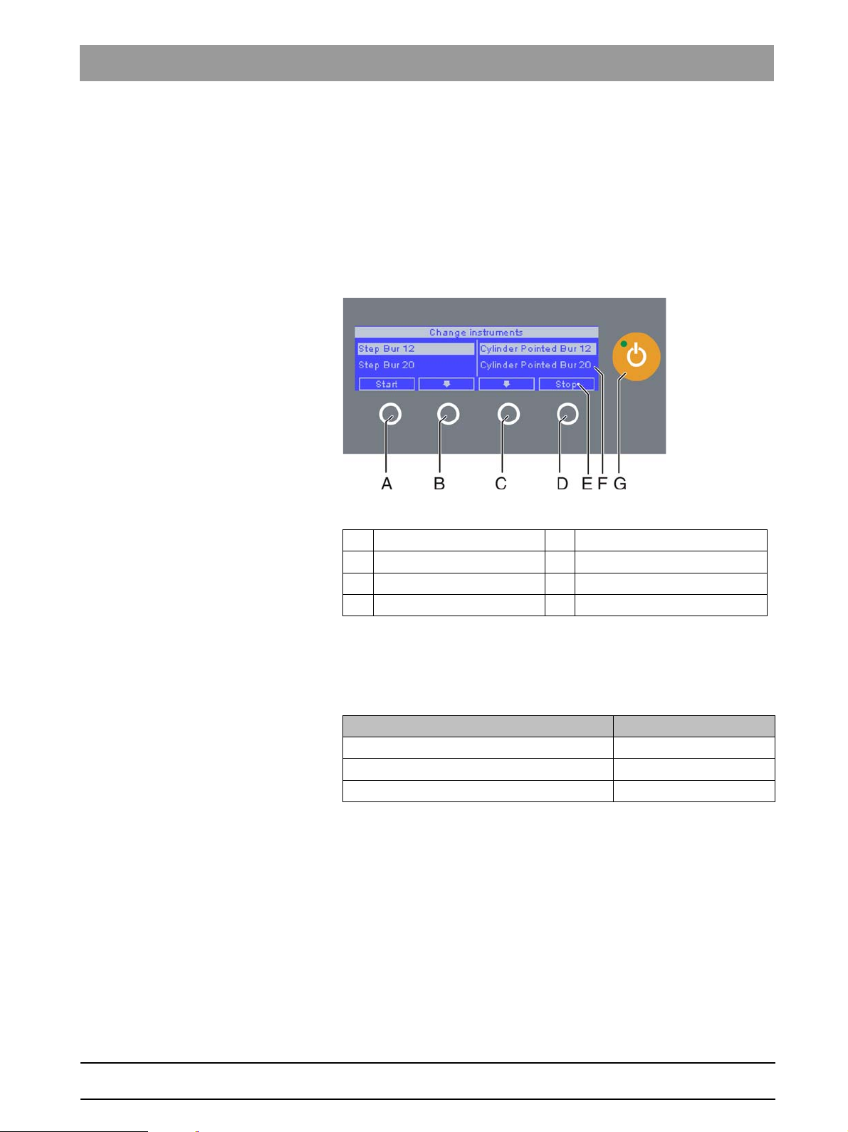
5.4.2 Display description
Display description
These operating instructions describe how to operate the unit by
executing and confirming commands via your PC.
You can also confirm commands such as
"Start", "Stop", "Cancel"
or
"OK"
directly on the display of your milling unit.
Possible commands are then shown above the corresponding button on
the display. In the example shown, button 1, (A) would confirm the
command
and button 4, (D) would confirm the command
"Stop"
.
"Start"
Display
A Button 1 E Command
B Button 2 F Display
C Button 3 G ON/OFF switch
D Button 4
5.4.3 Lighting of the milling chamber
Lighting of the milling chamber
The lighting of the milling chamber depends on the machining operation
involved:
Machining operation Lighting color
Mill white
Operation completed Green
Error or
"Stop"
button pressed Red
63 33 590 D 3439
D 3439.201.01.18.23 04.2012
17
Page 18

5 Installation and startup Sirona Dental Systems GmbH
15096.1.Rev.001
5.4 Initial startup Operating Instructions Sirona Dental CAD/CAM System
5.4.4 Inserting the milling chamber sieve
CAUTION Milling instruments
Inserting the milling ch amber sieve
CAUTION
Risk of injury from milling instruments
Be careful not to brush against the milling instruments with your hand.
CAUTION inLab milling chamber sieve
NOTICE
Risk of blockage in the cooling circuit
If chips enter into the cooling circuit of the machine, there is a risk that
the cooling circuit will become blocked.
➢ The sieve is suitable for all restoration and material types. It is
absolutely essential that no chips enter into the cooling circuit when
milling models.
Fragment: Inserting t he milling chamber s ieve
1. Remove the milling chamber sieve from the packaging.
2. Wet the underside of the sieve with water before insertion and press
it firmly against the floor of the milling chamber.
Fragment: Prerequisite s
When milling models, observe the following requirements:
Fragment CAUTION Usin g milling cutters i n inLab
NOTICE
Make sure the milling cutters are used correctly
If the milling cutters are not used as described below, this may cause
damage to the milling unit.
➢ Use the Shaper 25 and Finisher 10 milling cutters only in inLab MC
XL milling units, as of serial number 120 000 or in inLab MC XL
milling units that have been upgraded using the motor upgrade kit
for inLab (REF 6338631).
➢ Use the Shaper 25 and Finisher 10 milling cutters only for
manufacturing models from the inCoris S model (REF 6299361) and
inCoris L model blocks (REF 6299379).
5.4.5 Connecting the barcode reader
Connecting the barcode reader
Tool holder
➢ Insert the block clamp tool on the left and the bar code reader on the
right.
Block clamp tool for milling models
NOTICE
Using the block clamp tool
When milling models, the block clamp tool with 1.6 Nm is required. This
block clamp tool is also part of the milling model starter kit (REF 63 20
993).
18 D 3439.201.01.18.23 04.2012
63 33 590 D 3439
Page 19

Sirona Dental Systems GmbH 5 Installation and startup
15096.1.Rev.001
Operating Instructions Sirona Dental CAD/CAM System
Connecting the bar code reader
Connecting the bar code reader
➢ Plug the bar code reader into the serial interface to the rear of the
milling unit and secure with screws.
5.4.6 Installation
Installation
5.4.6.1
5.4.6.2
Connecting to the PC via LAN
Connecting to the PC via LAN
An Ethernet connection is located to the rear of the unit, which can be
used to connect the PC to the milling unit. Use a network cable to do this
(LAN connection).
Using a network cable
Connect the PC to the LAN connection of the unit.
If problems arise when connecting via a network cable, please read the
separate instructions "Operating the MC XL via LAN".
Connecting the milling unit to the power supply
Connecting the milling unit to the power supply
NOTICE
Grounded power outlet
63 33 590 D 3439
D 3439.201.01.18.23 04.2012
5.4.6.3
The milling unit must be connected to a grounded power outlet.
➢ Connect the milling unit to the power supply with the power cable
included in delivery.
Installing the unit
Installing the unit
You must connect the unit to the PC before putting it into operation. This
is described in the chapter "Connecting to the PC via LAN [ → 19]".
Searching for unit automatically
The unit is connected to the PC via a LAN cable.
Automatic unit search
1. Click the
2. Click on the
3. Click on the
"Configuration"
"Devices"
button in the system menu.
button.
"Scan for New Devices"
button.
All units connected to the PC are detected. For new devices, you
will be prompted to enter a name.
4. Enter a name for the new unit.
19
Page 20

5 Installation and startup Sirona Dental Systems GmbH
15096.1.Rev.001
5.4 Initial startup Operating Instructions Sirona Dental CAD/CAM System
Search for unit manually
The unit is connected to the PC via a LAN cable.
Manual unit search
1. Click the
2. Click on the
3. Click on the
"Configuration"
"Devices"
button in the system menu.
button.
"Add Device (Manual)"
button.
4. Select whether the unit is connected to the network or in series.
5. Network: Enter the network address.
In series: Enter the COM port and the baud rate.
6. Click on the
"Ok"
button.
The software attempts to establish contact with the unit.
If it fails to connect, check the connection. If required, consult a qualified
technician.
Header Removing the un it
Removing the unit
Removing the unit
✔ If you no longer require a unit (e.g. a unit is replaced), you can remove
it.
✔ The unit is operation.
1. Click the
2. Click on the
"Configuration"
"Devices"
3. Click on the unit that you wish to deinstall.
4. Click on the
"Delete Device"
You will be asked if you would like to remove the unit.
button in the system menu.
button.
button.
"YES"
5. Click on the
button.
The unit is removed.
20 D 3439.201.01.18.23 04.2012
63 33 590 D 3439
Page 21

Sirona Dental Systems GmbH 5 Installation and startup
A
A
D
C
B
15096.1.Rev.001
Operating Instructions Sirona Dental CAD/CAM System
5.4.7 Filling the water tank
Note on the tank cap opener
Filling the water tank
NOTICE
Using the tank cap opener
If you find the tank cap, tank drain or filter insert hard to open by hand,
use the tank cap opener (see "Using the tank cap opener" [ → 48]).
inLab water tank
Water tank
A Filter inserts C Tank
B Tank cap D Tank drain
Fragment Filling the inLab water tank
✔ The water tank has been drained, see "Removing water from the
unit" [ → 47].
1. Pull out the water tank at the front of the unit.
2. Turn the tank cap counter-clockwise and take it off.
NOTICE
Damage to surfaces!
When undiluted, DENTATEC milling additive etches plastic surfaces
and can cause discoloration.
➢ Do not place DENTATEC on the unit.
➢ Do not spill DENTATEC.
3. Add approx. 75 ml of DENTATEC to the tank.
4. Fill the tank with water until the filter inserts are completely immersed
(up to the bottom edge of the cover thread, approx. 3 liters).
5. Wait briefly until the filter inserts are soaked full and add a
corresponding amount of water.
6. Close the water tank by tightening the tank cap clockwise by hand.
Do not use the tank cap opener for this.
7. Push the water tank back into the housing.
63 33 590 D 3439
D 3439.201.01.18.23 04.2012
21
Page 22

5 Installation and startup Sirona Dental Systems GmbH
CD
192. 168. 230. 120
Pump
Config
?
15096.1.Rev.001
5.4 Initial startup Operating Instructions Sirona Dental CAD/CAM System
8. Switch the unit on (see Switching the unit ON and OFF [ → 22]).
9. Switch the pump on (press the
"Pump"
button) to fill the water circuit.
10. Fill the water tank up again until the filter inserts are completely
immersed (up to the bottom edge of the cover thread).
5.4.8 Switching the unit ON and OFF
Note on condensate
Switching the unit ON and OFF
NOTICE
Do not put the unit into operation at low temperatures!
If you move the unit to the operating site from a cold environment,
condensation may form and result in a short circuit.
The milling unit contains grease depots for lubricating components
which can cause error messages at low temperatures.
✔ Install the unit at room temperature.
➢ Wait until the unit has reached room temperature and is absolutely
dry (for at least one hour)
The unit is dry and can be put into operation.
Line voltage
NOTICE
Do not adjust the line voltage
The unit automatically adjusts to the line voltage.
Switching the unit on
✔ The milling unit is connected to the power supply.
1. The main switch on the rear side of the unit is set to position I (ON).
2. Press the ON/OFF button on the front panel.
The unit switches on and the display lights up.
Power-up display
22 D 3439.201.01.18.23 04.2012
When the milling unit is switched on, the display shows a picture of the
milling unit trying to contact the PC.
63 33 590 D 3439
Page 23

Sirona Dental Systems GmbH 5 Installation and startup
15096.1.Rev.001
Operating Instructions Sirona Dental CAD/CAM System
5.5
You can start or stop the water pump by pressing the
This enables you to drain the water circuit without connecting to the PC
(e.g. prior to transport) or fill the water circuit during startup.
You can call up the IP address by pressing the
can configure the milling unit in the network with this address.
"Pump"
"Config"
button (C).
button (D). You
Switching the unit off
✔ The unit has finished the machining operation.
➢ Briefly press the ON/OFF button on the front panel.
When you let go of the button, the unit switches off.
Repacking
Repacking
NOTICE
Repack only drained units!
Drain the unit! See "Removing water from the unit". [ → 47]
✔ The water tank is empty.
✔ The main switch on the back side of the unit is set to the 0 (OFF)
position.
1. Disconnect the power cable and the connecting cable from the back
side of the unit and stow them away.
2. Stow away the calibration tools in the drawer.
3. Check the unit for completeness according to the scope of supply!
4. Pack the unit securely.
5.6
5.7
Scope of supply
Scope of supply
The detailed scope of supply is specified in the document "Checklist
inLab MC XL".
Storage
Storage
NOTICE
Only drained units may be stored!
Drain the unit! See chapter on "Removing water from the unit". [ → 47]
Store the unit in a closed and dry room at a temperature of -10°C to 50°C
for a maximum period of 12 months.
63 33 590 D 3439
D 3439.201.01.18.23 04.2012
23
Page 24

6 Operation Sirona Dental Systems GmbH
15096.1.Rev.001
6.1 Configuration (inLab MC XL) Operating Instructions Sirona Dental CAD/CAM System
Operation
6
Operation
CAUTION
Risk of injury on calibration pins/milling instruments
If you reach into the milling chamber (e.g.: when inserting/removing a
ceramic block, changing milling instruments or inserting/removing a
calibration phantom), you may injure your hand on the calibration pins/
milling instruments.
Be careful not to brush against the calibration pins or milling instruments
with your hand.
Always insert your hand in the milling chamber underneath the
calibration pins and milling instruments.
6.1
Configuration (inLab MC XL)
Description
Configuration (inLab MC XL)
In the
"Devices"
1. Click the
2. Click on the
3. Click on the unit that you wish to configure.
inLab MC XL
inLab MC XL
You can subsequently edit the following settings via the menu item
:
XL"
●Name
● Connection settings
– Retrieve IP settings automatically
– Specify IP settings manually
● Manual block fixing
– If you use manual block fixing, a check mark must be placed in
front of
– Models can only be milled using manual block fixation.
● Second motor set
– The check mark must be placed in front of
area, various settings can be subsequently modified.
"Configuration"
"Devices"
"Manual block fixation"
button in the system menu.
button.
.
"Two Bur Sets"
"MC
.
24 D 3439.201.01.18.23 04.2012
– You can deactivate bur sets individually. A deactivated bur set
will simply be ignored during milling, calibration etc.
NOTICE! The restoration may be damaged if longer milling
instruments are present in the deactivated bur set than in the
active set. Ensure that the milling instruments installed in the
deactivated bur set are not longer than those in the active set.
● Scanner
– If the milling unit has an integrated scanner, a check mark must
be placed in front of
– Use the scanner to read bar codes.
"Scanner"
.
63 33 590 D 3439
Page 25

Sirona Dental Systems GmbH 6 Operation
15096.1.Rev.001
Operating Instructions Sirona Dental CAD/CAM System
● Bar code reader
– If a bar code reader is used, this option must be activated.
● External tank
– If the external water tank is connected and the check mark has
been placed, you will not be reminded to change the water until
a later point in time.
6.2
Calibrating the unit
Calibration tools
Calibrating the unit
NOTICE
Use only the supplied calibration tools
Use only the supplied calibration pins and the corresponding calibration
phantom when calibrating the milling unit.
Calibrating the inLab+CEREC SW4 milling unit
Unit calibrated ex works
The unit is calibrated at the factory. No additional calibration is required
during initial startup. Proceed as described below when performing a
subsequent calibration.
NOTICE
Faulty milling result
If the unit is not calibrated, the milling result may be faulty.
Preparing a calibration
1. Take the calibration pins and calibration phantom out of the drawer of
the unit.
2. In the software, navigate to the system menu, and click on the
"Configuration"
3. Click on the
4. Click on the unit that you wish to calibrate.
5. Click on the
If two bur sets are set:
A dialog box then opens where you can select the bur set to be
calibrated or the two bur sets to be calibrated consecutively. The
date of the last calibration is also displayed.
button.
"Devices"
"Calibrate"
button.
step.
63 33 590 D 3439
D 3439.201.01.18.23 04.2012
6. If necessary, select the desired bur set.
You can also select the desired bur set on the milling unit (up/down
arrow).
"Start"
7. Click on the
button.
The milling unit then moves into position to insert the calibration
tools.
A dialog box prompts you to insert the calibration pins and the
calibration phantom and to close the milling chamber door again.
25
Page 26

6 Operation Sirona Dental Systems GmbH
A
B
B
15096.1.Rev.001
6.2 Calibrating the unit Operating Instructions Sirona Dental CAD/CAM System
Inserting the calibration pins and phantom
1. Press the catch of the milling chamber door and open the door.
2. Loosen the milling instruments with the torque wrench and remove
them.
Calibration phantom
NOTICE
Grasp the calibration phantom correctly
Grasping the calibration phantom by its wide surfaces may cause
calibration errors.
➢ Always grasp the calibration phantom by its clamping shank (A)
when removing it from the storage box.
➢ Always grasp the calibration phantom by its narrow surfaces B when
inserting it into the block fixing.
3. Remove the adapter sleeve (see "Using the manual block
fixing [ → 31]“).
4. To insert the calibration phantom into the block fixing, grasp it by its
narrow surfaces B.
5. Clamp the calibration phantom with the ball pressure screw. Use the
block clamp tool for this purpose.
6. Insert the calibration pins in the motor mount by hand. Tighten the
corresponding chuck with the torque wrench until a clicking sound
can be heard.
7. Close the milling chamber door.
Performing a calibration
➢ Confirm your selection in the
"Start"
button.
The automatic calibration begins and takes approx. 12 minutes.
Wait until the calibration has been completed.
"Calibrate milling unit"
window with the
26 D 3439.201.01.18.23 04.2012
Inserting milling instruments
1. Open the milling chamber door following calibration.
2. Loosen the calibration pins with the torque wrench and remove them.
3. Loosen the ball pressure screw.
63 33 590 D 3439
Page 27

Sirona Dental Systems GmbH 6 Operation
15096.1.Rev.001
Operating Instructions Sirona Dental CAD/CAM System
4. Remove the calibration phantom by grasping it by its narrow surfaces
(B).
NOTICE
Store the calibration tools in a safe place
Store the calibration pins and the calibration body in a safe place (e.g.
in a storage box in the unit drawer).
5. Insert the milling instruments in the motor mount by hand. Tighten the
corresponding chuck with the torque wrench until a clicking sound
can be heard.
6. Close the milling chamber door.
The dialog box for selecting the milling instruments then appears.
7. Select the inserted milling instruments and confirm by clicking the
"Start"
button in the window.
The motor mounts move to their starting positions.
The
"Calibration succeeded"
Exiting the calibration
dialog box appears.
1. Click on the
"OK"
2. Click on the step
button.
"Exit Configuration"
.
63 33 590 D 3439
D 3439.201.01.18.23 04.2012
27
Page 28

6 Operation Sirona Dental Systems GmbH
15096.1.Rev.001
6.3 Starting the milling process Operating Instructions Sirona Dental CAD/CAM System
6.3
Starting the milling process
Starting the milling pro cess
Information on milling models
Information on milling models
IMPORTANT
Models can only be milled using inLab Stack software.
CAUTION when using milling cutters
NOTICE
Make sure the correct tools are used
Specific tools (milling cutters) are required for milling the models on the
MC XL. The milling cutters will be used as follows:
Set 1: Finisher 10
Set 2: Shaper 25
➢ Do not use the milling instruments for restorations in order to
produce models.
Fragment CAUTION Usin g milling cutters i n inLab
NOTICE
Make sure the milling cutters are used correctly
If the milling cutters are not used as described below, this may cause
damage to the milling unit.
➢ Use the Shaper 25 and Finisher 10 milling cutters only in inLab MC
XL milling units, as of serial number 120 000 or in inLab MC XL
milling units that have been upgraded using the motor upgrade kit
for inLab (REF 6338631).
➢ Use the Shaper 25 and Finisher 10 milling cutters only for
manufacturing models from the inCoris S model (REF 6299361) and
inCoris L model blocks (REF 6299379).
Removing chips
NOTICE
Chips gathered in the milling chamber
When milling models, a large number of chips collect in the milling
chamber.
➢ Each time a model block is milled, remove the chips from the milling
chamber by hand.
➢ Before removing them, squeeze the chips so that any stored water
is released into the cooling circuit.
Heading: Preparations
Preparations
Fragment Preparations
✔ Download or design a restoration (see operator's manual).
✔ You are in the
the settings, and positioned the restoration in the block.
➢ Click on the
The milling unit then moves to the insertion position.
"MILL"
phase and have selected the milling unit, tested
"Start Milling"
step.
28 D 3439.201.01.18.23 04.2012
63 33 590 D 3439
Page 29

Sirona Dental Systems GmbH 6 Operation
15096.1.Rev.001
Operating Instructions Sirona Dental CAD/CAM System
Heading: Starting the milling process
Starting the milling process
Fragment Starting the milling process
1. Depending on the configuration, you will be prompted to enter the bar
code (see also "Entering the bar code“).
2. Press the catch of the milling chamber door and open the door.
NOTICE
Error message during touch process!
Always be sure to insert the ceramic block that you selected for the
restoration. Otherwise an error message will be displayed during the
touch process.
3. Place the selected ceramic block in the block fixing.
4. Clamp the ceramic block with the ball pressure screw. Use the block
clamp tool for this purpose (see also "Using the manual block
fixing [ → 31]").
5. Close the milling chamber door and confirm the procedure by clicking
"Start"
.
The estimated time required for the milling process will then
appear in a message window.
NOTICE
Aborting the milling process
You can abort the milling process at any time by pressing the
"Stop"
button.
Heading: Terminating the milling process
Terminating the milling process
Fragment Terminating the milling process
1. When the milling process has been completed, open the milling
chamber door.
2. Remove the restoration.
WARNING
Risk of injury on the remainder of the ceramic block
The remaining portion of the ceramic block may have sharp edges
(e.g. A) that could injure you if it is not removed carefully.
Always grasp the remainder of the ceramic block by its metal holder.
3. Loosen the ball pressure screw.
4. Remove the remainder of the ceramic block. When removing the
remaining block from blocks with 6 mm diameter block holders, make
sure that the adapter sleeve remains in the machine.
5. Close the milling chamber door.
Defective milling results
CAUTION
63 33 590 D 3439
D 3439.201.01.18.23 04.2012
Do not use defective milling results!
Milling results must be judged by the user (dentist or dental technician)
and must not be used if defects are detected!
29
Page 30

6 Operation Sirona Dental Systems GmbH
15096.1.Rev.001
6.4 Entering the bar code Operating Instructions Sirona Dental CAD/CAM System
Open the milling chambe r door
NOTICE
If you have not used the milling unit for a rather long time, we
recommend you should switch it off and then open the milling chamber
door so that the milling chamber can dry out.
Heading: Seal of approval info
Information on the seal of approval
Fragment: Seal of approval info
Proper selection and processing of the material are decisive for the longterm clinical success of the restoration, especially in the case of zirconia.
However, different types of zirconia require individually matched machine
parameters. This is the reason why you can and must select different
types of zirconia in the inLab software. These machine parameters are
coordinated between Sirona and its material partners in complex
development processes. In addition to the desired fit and surface quality,
they also guarantee a maximum degree of material and equipment
safety. Consistently high quality of the milling result and the fit can be
guaranteed and damage to the milling machines can be excluded only if
certified materials are used.
Only zirconia that bears a seal of approval can be processed. If you still
use material without a seal of approval, one unit of the Sirona block
license (SBL) is required to start the milling process. To find out how
many units are still available, check the license manager. Please contact
your material partner if you require any additional Sirona block licenses.
6.4
Entering the bar code
Entering the bar code
Scanner active, Barcode Reader not active
If you have activated the option
dialog and the option
"Barcode Reader"
automatically be read by the scanner. You will be able to enter the
substitute code (8-digit character string, e.g. *1234XYZ) manually on the
PC only if this process fails.
Bar code reader active
Barcode Reader active
If you have activated the option
configuration dialog (e.g. for inCoris ZI), you must read in both bar codes
with the bar code reader. To do this, hold the bar code reader tilted to a
slight angle and move it over both of the bar codes on the block
continuously and evenly.
If the reading process fails, you can read-in the bar code once again by
pressing
"Retry"
(button 1 on the unit display). Alternatively, you also can
enter the substitute code (8-digit character string, e.g. *1234XYZ) on the
PC manually.
Scanner not active, bar code reader not active
Scanner not active, Barcode Reader not active
If neither the option
"Barcode Reader"
activated in the system configuration dialog, you always will be prompted
to enter the substitute code (8-digit character string, e.g. *1234XYZ) on
the PC manually.
"Scanner"
in the system configuration
is not active, the bar code will
"Barcode Reader"
in the unit
nor the scanner has been
30 D 3439.201.01.18.23 04.2012
63 33 590 D 3439
Page 31

Sirona Dental Systems GmbH 6 Operation
15096.1.Rev.001
Operating Instructions Sirona Dental CAD/CAM System
6.5
Using the manual block fixing
Using the manual block fixing
Store the block clamp tool in the corresponding holder (see also "Gluing
on the tool holder" [ → 18]).
You can attach the holder to a suitable location with the adhesive pad.
Clean and degrease the contact surface beforehand.
NOTE: Wear of the ball pressure screw
NOTICE
Wear of the ball pressure screw
The high clamping forces cause wear of the ball pressure screw.
➢ Replace the ball pressure screw every 500 clamping operations.
Blocks with 10 mm diameter block holders
Fastening the block
NOTICE
Fasten the block tightly
If the block is not tightened sufficiently, this may result in falsification of
the milling result and fracturing of its ceramic material.
➢ Fasten the block tightly using the block clamp tool with torque
wrench until you hear a click.
➢ Check to make sure that the block is seated very firmly.
Instructions for 10 mm diameter
1. Place the block (A) directly into the block fixing.
2. Clamp the ceramic block securely with the ball pressure screw (B).
Use the block clamp tool with torque wrench for this purpose.
The block is pressed laterally against the contact surface of the
block fixing and simultaneously pulled in axially. The plate of the
block holder thus rests on the block fixing.
63 33 590 D 3439
D 3439.201.01.18.23 04.2012
31
Page 32

6 Operation Sirona Dental Systems GmbH
15096.1.Rev.001
6.5 Using the manual block fixing Operating Instructions Sirona Dental CAD/CAM System
Blocks with 6 mm diameter block holders
Fastening the block
NOTICE
Fasten the block tightly
If the block is not tightened sufficiently, this may result in falsification of
the milling result and fracturing of its ceramic material.
➢ Fasten the block tightly using the block clamp tool with torque
wrench until you hear a click.
➢ Check to make sure that the block is seated very firmly.
1. Insert the adapter sleeve (A) into the block fixing.
NOTICE
Insert the adapter sleeve
The slot at the bottom end of the adapter sleeve must lie above the
radial pin of the block fastener in order to be inserted fully.
The hole for the ball pressure screw is then automatically in the correct
position, i.e. coincides with the threaded hole in the block fixing.
2. Insert the block (B) into the adapter sleeve.
3. Clamp the ceramic block securely with the ball pressure screw (C).
Use the block clamp tool with torque wrench for this purpose.
The block is pressed laterally against the contact surface of the
block fixing and simultaneously pulled in axially. The plate of the
block holder thus rests on the block fixing.
Removing the adapter sleeve
32 D 3439.201.01.18.23 04.2012
1. Loosen the ball pressure screw.
2. Place the block clamp tool in the inner groove (D) and pull out the
adapter sleeve.
63 33 590 D 3439
Page 33

Sirona Dental Systems GmbH 7 Maintenance
15096.1.Rev.001
Operating Instructions Sirona Dental CAD/CAM System
Maintenance
7
Maintenance, 1st note
Maintenance
NOTICE
Observe country-specific Regulations!
Some countries have legal regulations which require regular safety
inspections of electrical devices or systems by the operator.
Maintenance, 2nd note
NOTICE
Perform maintenance regularly!
Have maintenance performed on your unit annually by trained technical
personnel / a service engineer.
Maintenance, 3rd note
NOTICE
Observe error messages
You must observe error messages shown on the display on in the
software. If the error message does not disappear even after you have
performed the prompted action, contact your service engineer.
inLab cleaning intervals
NOTICE
Machine care
Interval: Once a week or after every 4th water change
➢ Change the filters (see Changing filters [ → 43])
➢ Clean the manual block chuck according to the the cleaning set
instructions (REF 61 77 161).
➢ Clean the clamping cones and chucks of the milling instruments
according to the cleaning set instructions (REF 61 77 161).
➢ If the jets of water do not strike the milling instruments, carefully
remove any foreign particles from the water nozzles with a probe.
Removing chips
NOTICE
Chips gathered in the milling chamber
When milling models, a large number of chips collect in the milling
chamber.
➢ Each time a model block is milled, remove the chips from the milling
chamber by hand.
➢ Before removing them, squeeze the chips so that any stored water
is released into the cooling circuit.
NOTICE
Do not confuse the block screw with the ball pressure screw
When operating an inLab milling unit and an inLab MC XL milling unit in
the same room, be careful not to confuse the block screw of the inLab
with the ball pressure screw of the inLab MC XL.
63 33 590 D 3439
D 3439.201.01.18.23 04.2012
33
Page 34

7 Maintenance Sirona Dental Systems GmbH
15096.1.Rev.001
7.1 Changing the water Operating Instructions Sirona Dental CAD/CAM System
Note on the tank cap opener
NOTICE
Using the tank cap opener
If you find the tank cap, tank drain or filter insert hard to open by hand,
use the tank cap opener (see "Using the tank cap opener" [ → 48]).
NOTE: Wear of the ball pressure screw
NOTICE
Wear of the ball pressure screw
The high clamping forces cause wear of the ball pressure screw.
➢ Replace the ball pressure screw every 500 clamping operations.
7.1
Changing the water
Changing the water
7.1.1 General information
General information
NOTICE
Damage to the pump and milling drives!
An excessively high ceramic content in the cooling water will damage
the pump and milling drives.
Change the water regularly!
When the water is due to be changed, a message window appears on
your monitor to remind you that it is time to change the water.
Preventing odors
All milling additives contain a biologically degradable preservative.
Despite this, however, odors may still develop under unfavorable
conditions.
Observe the following:
● Change the water at least once a week.
● With ambient temperatures above 25°C, change the water every 2 to
3 days to prevent foul odors.
34 D 3439.201.01.18.23 04.2012
● Drain the tank if you do not intend to operate the unit for more than
one week.
● Clean the tank if the odors recur.
● Add DENTATEC milling additive and fill the tank up to the brim with
water. Let it stand for at least 24 hours and then rinse it out thoroughly
with water once again.
NOTICE
Damage to surfaces!
When undiluted, DENTATEC milling additive etches plastic surfaces
and can cause discoloration.
➢ Do not place DENTATEC on the unit.
➢ Do not spill DENTATEC.
63 33 590 D 3439
Page 35

Sirona Dental Systems GmbH 7 Maintenance
A
A
D
C
B
15096.1.Rev.001
Operating Instructions Sirona Dental CAD/CAM System
NOTICE
Permissible milling additive
Use only DENTATEC as a milling additive.
7.1.2 Changing the water
Fragment Change the filter inserts regularly
Changing the water
NOTICE
Change the filter inserts regularly!
Replace both filter inserts after every fourth water change.
inLab water tank
Water tank
A Filter inserts C Tank
B Tank cap D Tank drain
Fragment Changing the water inLab + premium package
To change the water, proceed as follows:
✔ The unit is switched on.
✔ No milling/scanning process is running.
1. Pull out the water tank at the front of the unit.
2. Open the drain opening.
3. Empty two thirds of the water from the tank.
4. Close the drain opening.
5. Shake the tank vigorously.
6. Open the drain opening.
7. Drain the rest of the milling water.
8. Close the drain opening.
9. Turn the tank cap counter-clockwise and take it off.
63 33 590 D 3439
D 3439.201.01.18.23 04.2012
35
Page 36

7 Maintenance Sirona Dental Systems GmbH
15096.1.Rev.001
7.1 Changing the water Operating Instructions Sirona Dental CAD/CAM System
NOTICE
Foaming not permissible!
If any cleaning agents are used, this will create foam, which is not
permitted.
Do not use any cleaning agents.
10. Add approx. 75 ml of DENTATEC to the tank.
11. Fill the tank with water until the filter inserts are completely immersed
(up to the bottom edge of the cover thread, approx. 3 liters).
12. Wait briefly until the filter inserts are soaked full and add a
corresponding amount of water.
13. Close the water tank by tightening the tank cap clockwise by hand.
Do not use the tank cap opener for this.
14. Push the water tank back into the housing.
36 D 3439.201.01.18.23 04.2012
63 33 590 D 3439
Page 37

Sirona Dental Systems GmbH 7 Maintenance
15096.1.Rev.001
Operating Instructions Sirona Dental CAD/CAM System
7.2
Milling instruments
Milling instruments
7.2.1 Overview of materials and milling instruments
Overview of materials and milling instruments
If you primarily process materials from one group, equip both bur sets with
the same pair of milling instruments.
If you frequently process materials from different groups, equip the bur
sets as follows:
Milling instrument
"Left"
"Step Bur 20" "Cyl. Pointed Bur 20"
"Step Bur 12 S" "Cyl. Pointed Bur 12 S"
Milling instrument
"Right"
Bur set
Bur set 1
Bur set 2
63 33 590 D 3439
D 3439.201.01.18.23 04.2012
37
Page 38

7 Maintenance Sirona Dental Systems GmbH
15096.1.Rev.001
7.2 Milling instruments Operating Instructions Sirona Dental CAD/CAM System
7.2.2 Changing milling instruments (burs)
Changing milling instr uments (burs)
NOTICE
Milling instruments without chuck
In order to ensure that no grease residues from previously used chucks
remain in the clamping cone when using milling instruments without a
chuck, we urgently recommend degreasing the clamping cone.
NOTICE
Regular replacement of milling instruments
Change the milling instruments as soon as the system prompts you to
do this.
Change the milling instruments after using them to mill 25 restorations
at the latest.
Using the torque wrench
NOTICE
Using the torque wrench
When changing the milling tools to produce models, use only the torque
wrench that is marked with a red point (A) (REF 61 19 346). The torque
wrench is also part of the starter kit (REF 63 20 993).
Fragment CAUTION Usin g milling cutters i n inLab
NOTICE
Make sure the milling cutters are used correctly
If the milling cutters are not used as described below, this may cause
damage to the milling unit.
➢ Use the Shaper 25 and Finisher 10 milling cutters only in inLab MC
XL milling units, as of serial number 120 000 or in inLab MC XL
milling units that have been upgraded using the motor upgrade kit
for inLab (REF 6338631).
➢ Use the Shaper 25 and Finisher 10 milling cutters only for
manufacturing models from the inCoris S model (REF 6299361) and
inCoris L model blocks (REF 6299379).
✔ The torque wrench from the draw of the milling unit is ready-to-hand.
1. In the software, navigate to the system menu, and click on the
"Configuration"
2. Click on the
3. Click on the unit whose milling instruments you wish to replace.
If two bur sets are set:
A dialog box then opens where you can select the bur set to be
calibrated or the two bur sets to be calibrated consecutively. The
date of the last calibration is also displayed.
button.
"Devices"
button.
38 D 3439.201.01.18.23 04.2012
4. If necessary, select the desired bur set.
You can also select the desired bur set on the milling unit (up/down
arrow).
5. Click on the
"Start"
button.
63 33 590 D 3439
Page 39

Sirona Dental Systems GmbH 7 Maintenance
15096.1.Rev.001
Operating Instructions Sirona Dental CAD/CAM System
The motors travel to the change position for the milling
instruments.
The dialog box for changing the milling instruments opens.
6. Press the catch of the milling chamber door and open the door.
CAUTION
Risk of injury from milling instruments
If you put your hand in the milling chamber, you could injure it on the
milling instruments.
Be careful not to brush against the milling instruments with your hand.
Apply the torque wrench as shown.
7. Loosen the worn-out or defective milling instrument with the torque
wrench and pull it out manually.
NOTICE
Milling instrument without chuck
When replacing a milling instrument with chuck with a milling instrument
without chuck, remove the installed instrument chuck and degrease the
clamping cone.
8. NOTICE! Do not grease the milling instrument without chuck! Insert
the new milling instrument into the motor mount by hand. Tighten the
corresponding chuck with the torque wrench until a clicking sound
can be heard.
NOTICE
Faulty milling results
Interchanging milling instruments leads to faulty milling results.
9. Close the milling chamber door.
10. Select the milling instrument(s) you have inserted on the PC monitor
and click
You can also select the milling instruments on the milling unit (up/
down arrow) and confirm with
"Start"
.
"Start"
.
NOTICE
Cleaning cooling water nozzles
The cooling water nozzles in the milling chamber always must be kept
free of lime and milling dust deposits. The corresponding cooling water
jet always must strike the milling instrument accurately!
✔ The cooling water nozzles are dirty.
➢ Clean the nozzles with a cleaning wire and the SPRAYVIT syringe
(if available).
63 33 590 D 3439
D 3439.201.01.18.23 04.2012
39
Page 40

7 Maintenance Sirona Dental Systems GmbH
15096.1.Rev.001
7.3 Care and cleaning agents Operating Instructions Sirona Dental CAD/CAM System
Suitable milling instruments for inLab
NOTICE
Use only suitable milling instruments/milling cutters!
Do not use any milling instruments from CEREC 2 or CEREC 3 units.
If the milling cutters are not used as described below, this may cause
damage to the milling unit.
➢ Use the Shaper 25 and Finisher 10 milling cutters only in inLab MC
XL milling units, as of serial number 120 000 or in inLab MC XL
milling units that have been upgraded using the motor upgrade kit
for inLab (REF 6338631).
➢ Use the Shaper 25 and Finisher 10 milling cutters only for
manufacturing models from the inCoris S model (REF 6299361) and
inCoris L model blocks (REF 6299379).
Replacing a defective milling instrument
If a milling instrument breaks during a milling operation, the
corresponding motor travels to the change position. A dialog box which
marks the side with the broken milling instrument with a red cross then
opens.
7.3
✔ The milling instrument is broken.
1. Change the defective milling instrument as described above.
2. Select the milling instrument which you have inserted.
3. Press the
"Start"
button.
Care and cleaning agents
CAUTION: Approved care and cleaning agents
Care and cleaning agents
NOTICE
Approved care and cleaning agents
Use only care and cleaning agents which have been approved by
Sirona!
Care and cleaning agents, with REF number
A continuously updated list of approved agents can be downloaded from
the Internet at the address
the menu items
document
"SERVICE"
"Care and cleaning agents"
"www.sirona.com"
/
"Care and cleaning"
If you do not have any access to the Internet, please contact your dental
depot to order the list.
REF 59 70 905
. In the navigation bar, go to
and then open the
.
40 D 3439.201.01.18.23 04.2012
63 33 590 D 3439
Page 41

Sirona Dental Systems GmbH 7 Maintenance
15096.1.Rev.001
Operating Instructions Sirona Dental CAD/CAM System
7.4
Cleaning surfaces
Cleaning surfaces
NOTICE
Care and cleaning agents
Use only cleaning and care agents which have been approved by
Sirona, see Cleaning and care agents [ → 40].
NOTICE
Do not allow liquids to run into the ventilation slots!
7.4.1 Disinfecting
Disinfecting
Wipe surfaces down with a surface disinfectant (wiping disinfectant).
Observe the manufacturer’s instructions regarding restrictions for use.
7.4.2 Protection against medicaments
Protection against medicaments
Due to their high concentrations and the substances they contain, many
medicaments can dissolve, etch, bleach or discolor surfaces.
NOTICE
Damage to the surface
Clean the surface immediately with a moist cloth and a cleaning agent.
7.4.3 Cleaning
Cleaning
Remove dirt, grime and disinfectant residue regularly using mild,
commercially available cleaning agents.
63 33 590 D 3439
D 3439.201.01.18.23 04.2012
41
Page 42

7 Maintenance Sirona Dental Systems GmbH
15096.1.Rev.001
7.5 Replacing the main fuses Operating Instructions Sirona Dental CAD/CAM System
7.5
Replacing the main fuses
Warning: main fuse
Replacing the main fuse s
WARNING
Electric shock
Disconnect the power plug at the unit end before replacing the fuses.
NOTICE
Fuse type
Use only fuses of the same type in the fuse holder!
Fuse holder
A Cover C Fuse holder
BCC DFuse
Replacing fuses
Fuses: T5H250V Order No. 20 33 111
✔ The power plug must be disconnected.
1. Use a screwdriver to carefully pry off the cover of the fuses on the
back side of the unit.
2. Pull out the fuse holder.
3. Replace the defective fuses.
4. Reinsert the fuse holder.
5. Close the cover.
42 D 3439.201.01.18.23 04.2012
63 33 590 D 3439
Page 43

Sirona Dental Systems GmbH 7 Maintenance
A
A
D
C
B
15096.1.Rev.001
Operating Instructions Sirona Dental CAD/CAM System
7.6
Changing the filter
Fragment Changing the filter regularly inLab+premium package
Changing the filter
NOTICE
Change the filter inserts regularly!
Replace both filter inserts once a week or after every fourth water
change.
If a message stating that the water pressure is too low appears, you
must change the filter inserts.
Fragment Sirona filters only
NOTICE
Filter
Use only filter inserts approved by Sirona!
inLab water tank
63 33 590 D 3439
D 3439.201.01.18.23 04.2012
Water tank
A Filter inserts C Tank
B Tank cap D Tank drain
Fragment Changing the filter inLab+premium package
✔ The tank is drained, see "Removing water from the unit" [ → 47].
1. Pull out the water tank at the front of the unit.
2. Unscrew the covers on the side and take them out of the tank along
with the filter inserts.
3. Rinse the water tank.
4. Insert the new filters with cover into the tank and screw them tight.
5. Fill the tank, see "Changing the water“ [ → 34].
Filter insert: Order No. 61 29 519
43
Page 44

7 Maintenance Sirona Dental Systems GmbH
15096.1.Rev.001
7.6 Changing the filter Operating Instructions Sirona Dental CAD/CAM System
7.6.1 Changing filters on the external tank
Changing filters on the external tank
Cleaning the plug-in tank
1. Pull out the plug-in tank.
2. Clean the outlet (A) and then rinse it with water.
3. Reinsert the plug-in tank.
Opening the external wat er tank
Opening the external water tank
NOTICE
Risk of damage to the hoses
If you pull on the hose, you may damage it.
➢ Always pull it from the pipe section (A or B).
1. Pull off the suction connection (A).
2. Pull off the drain hose (B).
3. Open the clamping ring and lay it down.
44 D 3439.201.01.18.23 04.2012
63 33 590 D 3439
Page 45

Sirona Dental Systems GmbH 7 Maintenance
15096.1.Rev.001
Operating Instructions Sirona Dental CAD/CAM System
Disposing of filter cartridges and ceramic sludge
Disposing of filter cartridges and ceramic sludge
1. Release the filter cartridges by tilting them slightly. The springs
remain attached.
Tip: If a spring accidentally comes loose, you can reattach it by
screwing it in counter-clockwise.
2. Dispose of the filter cartridges with domestic waste.
3. Slowly pour the water out of the container into the outlet so that the
ceramic sludge remains in the container.
4. Take the plastic bag out of the container and dispose of it with
domestic waste.
Preparing the External Water Tank
Preparing the external water tank
1. Insert the plastic bag into the external water tank in such a way that
it protrudes by around 3-4 cm.
2. Ensure that it protrudes evenly around the edge of the container.
3. Place the clamping ring onto the external water tank with the labeling
(A) facing up.
4. Add approx. 400 ml of DENTATEC to the tank.
63 33 590 D 3439
D 3439.201.01.18.23 04.2012
45
Page 46

7 Maintenance Sirona Dental Systems GmbH
15096.1.Rev.001
7.6 Changing the filter Operating Instructions Sirona Dental CAD/CAM System
5. Fill the tank up to the filling level with water (approx. 16 liters).
Installing the filters
Installing the filters
1. Press down the 2 filters until they click into place on the lid.
2. Insert the lid with the filters into the container.
3. Close the clamping ring.
63 33 590 D 3439
46 D 3439.201.01.18.23 04.2012
Page 47

Sirona Dental Systems GmbH 7 Maintenance
15096.1.Rev.001
Operating Instructions Sirona Dental CAD/CAM System
Connecting the External Water Tank
Connecting the External Water Tank
1. Insert the suction connection up to the stop.
2. Insert the drain hose up to the stop.
NOTICE
Risk of overflowing
Sagging of the drain hose may result in overflowing.
➢ Arrange the external water tank in such a way that there is a
continuous incline in the drain hose (you may need to rotate or move
the external water tank).
7.7
Removing water from the unit
Removing water from t he unit
You must remove water from the unit if you will not be using it for a longer
period of time or wish to transport it.
✔ No milling process is running.
1. Switch off the unit.
2. Pull out the water tank at the front of the unit.
3. Drain the water out of the water tank through the drain opening and
reinsert the water tank in the unit.
4. Switch the unit on.
NOTICE
Pump button active at power-up
"Pump"
The
switched on. You can start or stop the water pump by pressing this
button.
5. Press the
The water pump then starts pumping the water out of the unit.
6. Press the
7. Pull out the water tank and empty it.
8. Push it back into the housing.
button appears on the display when the milling unit is
"Pump"
key to switch the pump on.
Let the pump run until no more water escapes from the nozzles.
"Pump"
key to switch the pump off.
63 33 590 D 3439
D 3439.201.01.18.23 04.2012
47
Page 48

7 Maintenance Sirona Dental Systems GmbH
15096.1.Rev.001
7.8 Using the tank cap opener Operating Instructions Sirona Dental CAD/CAM System
7.8
Using the tank cap opener
Using the tank cap opener
NOTICE
Risk of damage to the tank
Use the tank cap opener only for opening the tank cap, tank drain and
filter insert.
Do not use the tank cap opener for closing the tank cap. To close the
tank cap, tank drain and filter insert it is sufficient to tighten them
clockwise by hand.
Opening the tank cap
✔ The water tank has been pulled out and drained.
➢ Place the tank cap opener on the tank cap as shown, and take off the
tank cap by unscrewing it counter-clockwise.
Opening the filter cap
✔ The water tank has been pulled out and drained.
➢ Place the tank cap opener on the filter cap as shown, and take off the
filter cap by unscrewing it counter-clockwise.
48 D 3439.201.01.18.23 04.2012
63 33 590 D 3439
Page 49

Sirona Dental Systems GmbH 7 Maintenance
15096.1.Rev.001
Operating Instructions Sirona Dental CAD/CAM System
Opening the tank drain
✔ The water tank has been pulled out.
➢ Place the tank cap opener on the filter drain as shown, and take off
the filter drain by unscrewing it counter-clockwise.
63 33 590 D 3439
D 3439.201.01.18.23 04.2012
49
Page 50

8 Technical description Sirona Dental Systems GmbH
15096.1.Rev.001
8.1 System requirements Operating Instructions Sirona Dental CAD/CAM System
Technical description
8
Technical description
8.1
8.2
System requirements
System requirements
The inLab SW software may be installed only on the 64-bit inLab PC.
The hardware version of the inLab PC must be HQ PC Hardware with
Windows 7 (64-bit) or higher.
milling unit
milling unit
8.2.1 General technical description
Technical description of the milling unit
General technical de scription
● Digital feed control with force monitoring for extremely sensitive
processing of ceramic materials
● Process-controlled milling motors
● Positioning step size: 6.25 μm
● Milling repeatability: +/- 25 μm
● Milling speed: 1.0 - 1.5 mm/min.
Milling instruments (performance-monitored, backlash-free bearing)
● Grain size: 64 μm
● Speed: 42.000 rpm
● Step Bur 12 S
● Step Bur 20
● Cyl. Pointed Bur 12 S
● Cyl. Pointed Bur 20
50 D 3439.201.01.18.23 04.2012
63 33 590 D 3439
Page 51

Sirona Dental Systems GmbH 8 Technical description
15096.1.Rev.001
Operating Instructions Sirona Dental CAD/CAM System
8.2.2 Technical data
Technical data
Type designation Milling unit inLab MC XL
Rated line voltage 100V - 230V AC
Rated power frequency 50/60 Hz
Rated current 1.5 - 3.5 A
Nominal power output 320 VA
Permissible line voltage fluctuations ±10% of nominal voltage
Type of protection against electric
shock
Degree of protection against ingress
of water
Overvoltage category II
Ambient conditions For indoor use
Temperature range 5 ℃ to 40 ℃
Humidity range 80% rel. up to 31°C
Operating mode Continuous operation
Dimensions (WxHxD) in mm 700 x 425 x 420
Approx. weight 43 kg
Class 1 device
Ordinary device (without
protection against ingress of
water)
Pollution degree 2
Barometric pressure: 700 hPa –
1060 hPa
decreasing to
50% rel. up to 40°C
8.2.3 Controller board
Controller board
● 3x 2-axis stepping motor controller with microstepping
● 4 DC motor controllers with integrated speed and current control and
force monitoring
● Ethernet, RJ45 interface 10 Mbit/sec
63 33 590 D 3439
D 3439.201.01.18.23 04.2012
51
Page 52

9 Disposal Sirona Dental Systems GmbH
15096.1.Rev.001
Operating Instructions Sirona Dental CAD/CAM System
Disposal
9
Disposal
Your product is marked with the adjacent symbol. Within the European
Economic Area, this product is subject to Directive 2002/96/EC as well as
the corresponding national laws. This directive requires environmentally
sound recycling/disposal of the product. The product must not be
disposed of as domestic refuse!
Please observe the disposal regulations applicable in your country.
Disposal procedure
Please note that this product is subject to the stipulations in EC Directive
2002/96 governing waste electrical and electronic equipment and must
be disposed of in line with these special requirements within the
European Union (EU).
Prior to disassembly / disposal of the product, it must be fully prepared
(cleaned / disinfected / sterilized).
When disposing of equipment permanently, please proceed as follows:
In Germany:
To initiate return of the electrical device, please send a disposal order to
"enretec GmbH".
1. You can find a form for placing a disposal order on the company's
homepage (www.enretec.de) under the menu item "Entsorgung
elektrischer und elektronischer Geräte" (Disposal of electric and
electronic devices). The form can either be downloaded or completed
online.
2. Fill out the form with the corresponding details and send it as an
online order or fax it to enretec GmbH at +49(0)3304 3919 590.
You can also get in touch with the following contacts for disposal
orders and any questions relating to this you may have:
Phone: +49(0)3304 3919 500;
E-mail: pickup@eomRECYCLING.com
Mailing address: enretec GmbH, Geschäftsbereich eomRECYCLING
Kanalstrasse 17, 16727 Velten
Any nonpermanently installed equipment will be picked up at its
installation site in the practice. Permanently installed equipment will
be picked up curbside at your address by appointment.
All disassembly, transport and packaging costs are to be borne by the
owner/operator of the equipment. The disposal itself is free of charge.
Worldwide (outside Germany):
Please contact your local dental equipment specialist for country-specific
information on disposal.
52 D 3439.201.01.18.23 04.2012
63 33 590 D 3439
Page 53

Sirona Dental Systems GmbH
15096.1.Rev.001
Operating Instructions Sirona Dental CAD/CAM System
Index
B
Barcode reader, 15
Building installation, 11
C
Calibration tools
Calibration phantom, 25
Calibration pins, 25
Storage, 27
Care and cleaning agents, 41
approved care and cleaning agents, 40
Download of updated list, 40
CE mark, 8
Changing
Milling instruments, 38
Connection
Ethernet, 19
LAN, 19
Cooling water nozzles, 39
D
Dimensions, 51
Disinfectant, 41
Disposal
Disposal of electronic and electrical equipment, 52
E
F
Filter
Order No., 43
filter
change, 43
floor space, 14
Fuse, 15
Fuse type, 42
Order No., 42
replacement, 42
H
Humidity range, 51
I
Installation site, 14
Installing the unit
removing, 20
installing unit
manually, 20
M
Main switch, 15
Maintenance, 11
Regulations, 33
Milling instruments, 40, 50
Replacing a defective instrument, 40
Ethernet
LAN port, 15
63 33 590 D 3439
D 3439.201.01.18.23 04.2012
Milling speed, 50
Milling unit
Display, 17
Milling chamber, 16
Overview, 15
O
Operating mode, 51
53
Page 54

Sirona Dental Systems GmbH
15096.1.Rev.001
Operating Instructions Sirona Dental CAD/CAM System
P
Packaging, 13
Packing, 23
Ports, 15
Power connection, 15
Product safety, 12
Protection class, 51
R
Rated current, 51
Rated line voltage, 51
Repair, 11
S
Safety information, 6
Scope of supply, 23
T
Temperature range, 51
Transport, 13
Type designation, 51
U
Unit installation
automatically, 19
Unpacking, 13
W
Warranty, 7
Water, 51
Water tank
Change water, 35
Filling the, 21
Weight, 51
54 D 3439.201.01.18.23 04.2012
Odors, 34
Overview, 21, 35, 43
Removing water from the unit, 47
Water change, 34
63 33 590 D 3439
Page 55

15096.1.Rev.001
Page 56

tЙ=кЙлЙкоЙ=нЬЙ=кбЦЬн=нз=г~вЙ=~еу=~днЙк~нбзел=пЬбЕЬ=г~у=ДЙ=кЙимбкЙЗ=ЗмЙ=нз=нЙЕЬебЕ~д=бгйкзоЙгЙенлK
15096.1.Rev.001
«=pбкзе~=aЙен~д=pулнЙгл=dгДe=OMMSJOMNO pйк~ЕЬЙW ЙеЦдблЕЬ=ErpF mкбенЙЗ=бе=dЙкг~еу
a=PQPVKOMNKMNKNUKOP MQKOMNO ûKJkêKW= NNR=RVM
pбкзе~=aЙен~д=pулнЙгл=dгДe
c~Дкбвлнк~≈Й=PN
SQSOR=_ЙелЬЙбг
dЙкг~еу
пппKлбкзе~KЕзг
áå=íÜÉ=rp^W
pбкзе~=aЙен~д=pулнЙгл=ii`
QUPR=pбкзе~=aкбоЙI=pмбнЙ=NMM
`Ь~кдзннЙI=k`=OUOTP
rp^
lêÇÉê=kç
SP=PP=RVM=a=PQPV
 Loading...