

Page 1
kÉï=~ë=çÑW=
HELIODENT
PLUS
7mA DC7mA DC
70kV 60kV
S
00
8
.
HELIODENTHELIODENT
PLUS
7mA DC
70kV 60kV
S
00
8
.
NMKOMNS
ebiflabkq
pЙкобЕЙ=j~ем~д
mirp
Cover page
bеЦдблЬ
bеЦдблЬ
=
Page 2

Page 3

Sirona Dental Systems GmbH Table of contents
Service Manual HELIODENT
PLUS
Table of contents
1
General information.................................................................................................. 7
1.1 Structure of the document............................................................................. 7
1.1.1 Identification of the danger levels..................................................... 7
1.1.2 Formats and symbols used .............................................................. 7
1.2 General safety information ............................................................................ 8
1.3 Operation notes............................................................................................. 9
1.4 Changing the device configuration................................................................ 11
1.4.1 Changing the cone length ................................................................ 11
1.4.2 Using and changing a diaphragm .................................................... 11
1.5 Measures when exchanging spare parts ...................................................... 12
1.5.1 Safety-related tests .......................................................................... 12
1.6 Demo mode................................................................................................... 13
1.7 List of software versions................................................................................ 14
1.8 Round and angular support arm system ....................................................... 14
1.9 The most important subassemblies .............................................................. 15
1.10 Labeling......................................................................................................... 17
1.11 Removing covers .......................................................................................... 19
1.11.1 Wall module ..................................................................................... 19
1.11.2 Remote control and remote timer..................................................... 20
1.11.3 X-ray tube unit.................................................................................. 21
bеЦдблЬ
1.12 Overview of PC boards ................................................................................. 22
1.12.1 Generator board DX1....................................................................... 22
1.12.2 Control board DX4 ........................................................................... 23
1.13 Required items .............................................................................................. 24
1.13.1 Additional documents....................................................................... 24
1.13.2 Tools and auxiliary materials............................................................ 24
2
62 15 102 D3507
D3507.076.01.13.02 10.2016
List of messages ...................................................................................................... 25
2.1 Error messages............................................................................................. 25
2.1.1 General ............................................................................................ 25
2.1.2 Structure........................................................................................... 25
2.1.3 List of error messages...................................................................... 26
3
Page 4

Table of contents Sirona Dental Systems GmbH
Service Manual HELIODENT
PLUS
3
Troubleshooting....................................................................................................... 29
3.1 Error message: NONE ................................................................................. 29
3.2 Error message: E5 01 02 / E5 01 14 / E5 01 12.......................................... 32
3.3 Error message: E5 01 22 ............................................................................. 33
3.4 Error message: E6 01 23 ............................................................................. 34
3.5 Error message: E7 01 01 ............................................................................. 36
3.6 Error message: E7 04 51 - Door contact error ............................................. 38
4
Maintenance............................................................................................................ 39
4.1 Checking the shielding ................................................................................. 39
4.1.1 Test ................................................................................................. 39
4.1.2 Positions.......................................................................................... 39
4.2 Checking the protective ground connections ............................................... 41
4.2.1 Test ................................................................................................. 41
4.2.2 Positions.......................................................................................... 41
4.3 Checking exposure time and high voltage kV .............................................. 43
4.4 Checking the deadman function................................................................... 44
4.5 Checking the release button......................................................................... 45
4.5.1 General............................................................................................ 45
4.5.2 Release button on PC board DX1 (coiled cable)............................. 45
4.5.3 Release button on PC board DX4 (coiled cable)............................. 46
4.5.4 Release button on front panel on PC board DX4............................ 47
4.6 Checking the front panel .............................................................................. 48
4.6.1 Visual check .................................................................................... 48
4.6.2 Front panel test ............................................................................... 48
4.7 Checking and adjusting the support arm...................................................... 50
4.7.1 Round support arm system ............................................................. 50
4.7.2 Angular support arm system ........................................................... 51
4.7.2.1 Checking and adjusting the angular scissor arm.............. 51
4.7.2.2 Checking and adjusting the angular scissor arm is parallel 52
4.8 Checking the X-ray tube assembly joint....................................................... 54
4.9 Checking the ceiling model .......................................................................... 57
4.10 Checking HELIODENT PLUS on the mobile stand...................................... 59
4.11 Checking the tube current ............................................................................ 60
4.12 Checking the protective ground wires .......................................................... 61
4.13 Checking the unit leakage current................................................................ 63
4.14 Checking insulation resistance on the power supply cord of the mobile stand 64
4 D3507.076.01.13.02 10.2016
62 15 102 D3507
Page 5

Sirona Dental Systems GmbH Table of contents
Service Manual HELIODENT
PLUS
5
Service routines........................................................................................................ 65
5.1 Operation ...................................................................................................... 65
5.2 Overview ....................................................................................................... 66
5.3 Service routines (list)..................................................................................... 67
5.3.1 Service routine S01.......................................................................... 67
5.3.2 Service routine S02.......................................................................... 67
5.3.3 Service routine S03.......................................................................... 67
5.3.4 Service routine S04.......................................................................... 67
5.3.5 Service routine S05.......................................................................... 68
5.3.6 Service routine S06.......................................................................... 68
5.3.7 Service routine S07.......................................................................... 69
5.3.8 Service routine S08.......................................................................... 69
5.3.9 Service routine S09.......................................................................... 69
5.3.10 Service routine S10.......................................................................... 70
5.3.11 Service routine S11.......................................................................... 70
5.3.12 Service routine S12.......................................................................... 70
bеЦдблЬ
5.3.13 Service routine S13.......................................................................... 71
5.3.14 Service routine S14.......................................................................... 71
5.3.15 Service routine S15.......................................................................... 72
5.3.16 Service routine S16.......................................................................... 73
5.3.17 Service routine S17.......................................................................... 73
5.3.18 Service routine S18.......................................................................... 74
5.3.19 Service routine S19.......................................................................... 74
5.3.20 Service routine S20.......................................................................... 75
5.3.21 Service routine S21.......................................................................... 75
5.3.22 Service routine S22.......................................................................... 75
5.3.23 Service routine S23.......................................................................... 76
5.3.24 Service routine S24.......................................................................... 76
5.3.25 Service routine S25.......................................................................... 76
5.3.26 Service routine S26.......................................................................... 77
5.3.27 Service routine S27.......................................................................... 77
5.3.28 S28 service routine .......................................................................... 78
5.3.29 Service routine S29.......................................................................... 78
62 15 102 D3507
D3507.076.01.13.02 10.2016
5
Page 6

Table of contents Sirona Dental Systems GmbH
Service Manual HELIODENT
PLUS
6
Repair....................................................................................................................... 79
6.1 Safety-related tests ....................................................................................... 79
6.2 Replacing X-ray tube assembly H1............................................................... 79
6.3 Replacing PC board DX1 .............................................................................. 85
6.3.1 Removing a defective board DX1 .................................................... 85
6.3.2 Installing the new board DX1 ........................................................... 86
6.3.3 Connection in the control panel for cable L2.................................... 87
6.3.4 Connecting the power cable............................................................. 87
6.3.5 Attach the EMC additional plate for the wall adapter to the power
88
supply
6.4 Replacing PC board DX4 .............................................................................. 89
6.5 Replacing the power supply cord for the mobile stand ................................. 90
6 D3507.076.01.13.02 10.2016
62 15 102 D3507
Page 7
Sirona Dental Systems GmbH 1General information
Service Manual HELIODENT
PLUS
General information
1
1.1Structure of the document
1.1
Structure of the document
1.1.1 Identification of the danger levels
To prevent personal injury and material damage, please observe the
warning and safety information provided in these operating instructions.
Such information is highlighted as follows:
DANGER
An imminent danger that could result in serious bodily injury or death.
WARNING
A possibly dangerous situation that could result in serious bodily injury
or death.
CAUTION
A possibly dangerous situation that could result in slight bodily injury.
NOTICE
A possibly harmful situation which could lead to damage of the product
or an object in its environment.
bеЦдблЬ
IMPORTANT
Application instructions and other important information.
Tip: Information on making work easier.
1.1.2 Formats and symbols used
The formats and symbols used in this document have the following
meaning:
Prerequisite
1. First action step
2. Second action step
or
➢ Alternative action
Result
➢ Individual action step
See "Formats and symbols
used [ → 7]"
● List Designates a list.
"Command / menu item" Indicates commands, menu items or
Prompts you to do something.
Identifies a reference to another text
passage and specifies its page
number.
quotations.
62 15 102 D3507
D3507.076.01.13.02 10.2016
7
Page 8
1General information Sirona Dental Systems GmbH
1.2General safety information Service Manual HELIODENT
PLUS
1.2
General safety information
WARNING
Radiation protection
The valid radiation protection regulations and measures must be
observed. The statutory radiation protection equipment must be used.
In case of malfunctions, cancel the exposure immediately by letting go
of the exposure release button.
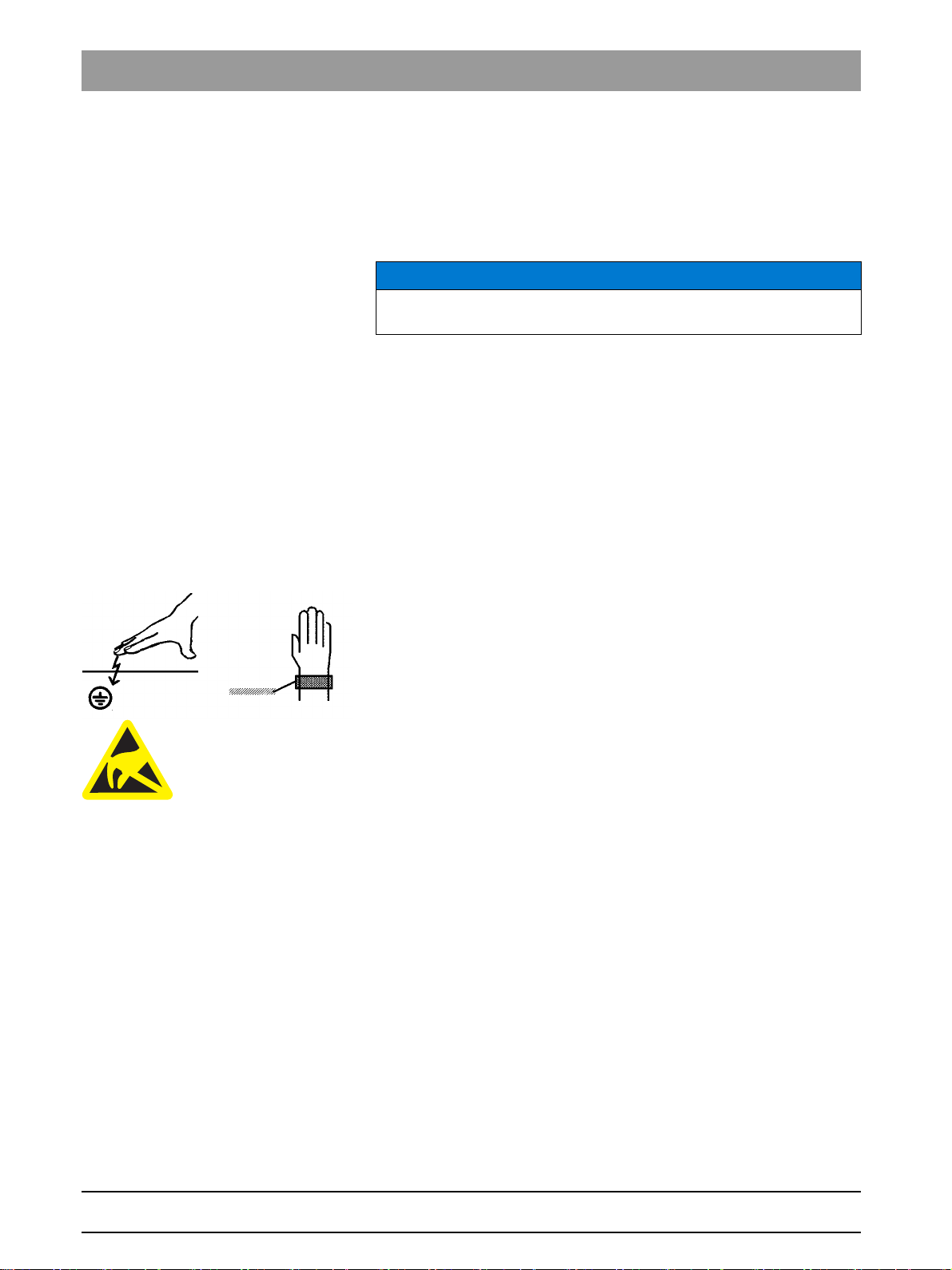
Handling boards
CAUTION
Electrical components of the unit can be destroyed.
Prior to opening the unit
➢ Please comply with the usual precautionary measures for handling
printed circuit boards (ESD).
➢ Make sure you touch a ground point to discharge yourself prior to
touching the components.
➢ Use an ESD wrist band and connect it to the protective ground wire.
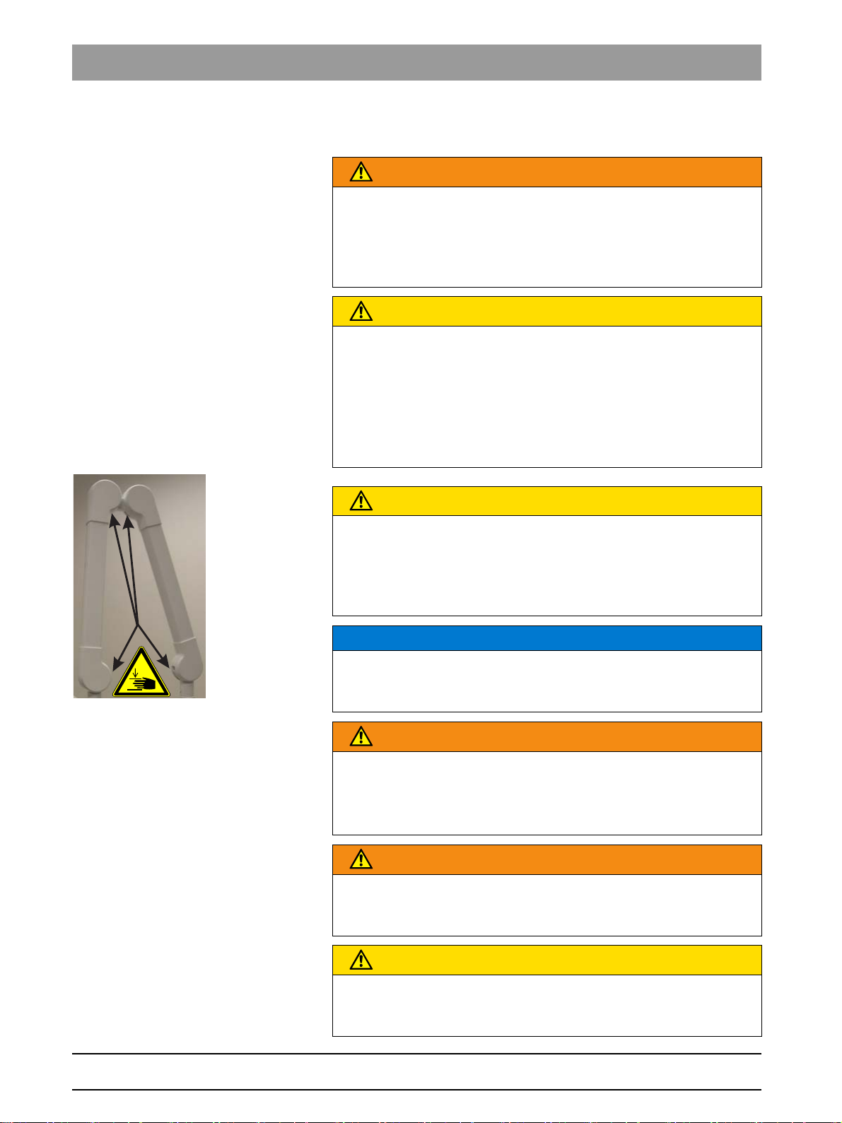
Risk of crushing
CAUTION
Gaps appear between the internal hinges when moving the angular
support arm.
Fingers may be crushed in these gaps.
➢ Ensure that you never place your fingers in the gaps between the
hinges, neither during operation nor for cleaning purposes.
Installation by authorized personnel
NOTICE
Operational reliability
Installation and servicing may be performed only be personnel
specifically authorized by Sirona.
Power connection
WARNING
Shock hazard
People can be injured or electrical components of the unit destroyed.
➢ It is essential that you switch off the unit PRIOR to beginning the
installation or servicing.
Modification to the product
WARNING
Modifications to the product
Modifications which may affect the safety of the operators or third
parties are prohibited by law!
Support arm system additiona l co mponents
CAUTION
No additional components on the support arm system
It is not permissible to fix additional components to the support arm
system.
62 15 102 D3507
8 D3507.076.01.13.02 10.2016
Page 9
Sirona Dental Systems GmbH 1General information
Service Manual HELIODENT
PLUS
1.3Operation notes
1.3
Nominal line voltage
Remote control The unit may be equipped with a remote control to be used inside the
Switch-on procedure
Operation notes
Nominal voltage: 120V, 200V– 240V
Permissible fluctuation: ± 10%
Rated current: At 120 V: 10 A
At 200 – 240 V: 6 – 5 A
Nominal frequency: 50/60 Hz
Internal line impedance: At 120 V 0.3 ohms
At 200 – 240 V 0.8 ohms
treatment room or outside of the X-ray room.
The release button with coiled cable can/must be removed from the
remote control and connected directly to the unit for testing.
Keep in mind that the disconnected cable may be the cause of defects.
NOTICE
Do not press any buttons when switching on the unit!
➢ Switch the unit on.
ª It will execute an electronic self-testing routine.
bеЦдблЬ
ª The operational readiness indicator must be lit up.
Cooling period The cooling period between two exposures is maintained by an automatic
exposure blocking function according to the pulse/pause ratio.
Software version The DX4 board determines the software version.
You can find the software version with the following steps:
● Start service routine "2."
● A label next to the main switch includes an imprint of the software
version.
Disturbance of electronic equipment
caused by cell phones
Disposal
To ensure safe operation of medical electrical equipment, the use of
mobile wireless phones in practice or hospital environments is prohibited.
General
Environmentally sound dis posal
In accordance with Directive 2012/19/EU and national disposal
regulations regarding old electrical and electronic devices, please be
advised that such items must be disposed of in a special way within the
European Union (EU). These regulations require environmental friendly
usage/disposal of old electrical and electronic devices. Such items must
not be disposed of as domestic refuse. This has been expressed using
the icon of the “crossed out trash can” since March 24, 2006, amongst
other methods.
62 15 102 D3507
D3507.076.01.13.02 10.2016
Please observe the disposal regulations applicable in your country.
9
Page 10

1General information Sirona Dental Systems GmbH
1.3Operation notes Service Manual HELIODENT
PLUS
X-ray tube unit
The X-ray tube assembly contains a tube which can implode, lead lining,
and mineral oil.
Removing covers Observe the section on "Removing covers".
Measurements Observe the following when taking measurements:
● Always switch the unit off before connecting a measuring instrument.
● Select the correct current/voltage type and adjust the measuring
range to match the expected readings.
● Perform continuity tests only on units which are switched off.
● If several exposures with radiation must be taken to check a
measurement, make sure that the prescribed cool-down intervals are
observed.
– They are maintained by an automatic exposure blocking function
(see Operating Instructions).
● Observe the radiation protection guidelines before releasing the
radiation.
10 D3507.076.01.13.02 10.2016
62 15 102 D3507
Page 11

Sirona Dental Systems GmbH 1General information
Service Manual HELIODENT
PLUS
1.4Changing the device configuration
1.4
Changing the device configuration
1.4.1 Changing the cone length
Explanation
If the cone length is changed, this change must be registered with service
routine S06 [ → 68].
1.4.2 Using and changing a diaphragm
Explanation
If a diaphragm needs to be used, this change must be registered with
service routine S07 [ → 69].
If a diaphragm is replaced or removed, this change must also be
registered with service routine S07 [ → 69].
bеЦдблЬ
62 15 102 D3507
D3507.076.01.13.02 10.2016
11
Page 12
1General information Sirona Dental Systems GmbH
1.5Measures when exchanging spare parts Service Manual HELIODENT
PLUS
1.5
Measures when exchanging spare parts
Spare parts
The article numbers for ordering spare parts can be found in the spare
parts list, Order No. 62 34 111
NOTICE
The diagrams contained in the spare parts list provide a useful guide
when replacing parts.
Preparation
➢ Always switch the unit off before replacing parts.
Replacement
The following must be observed when replacing individual
subassemblies:
● The unit must be disconnected from the power supply before
replacing any parts near the power supply, the power switch, or the
power supply board.
Disconnect the unit from the junction box of the building installation.
● Always wear an ESD wrist band to protect sensitive components on
printed circuit boards (ESD) and attach it to a ground conductor
(green/yellow).
● Always check the unit after replacing PC boards DX1 and DX4 or the
X-ray tube assembly.
● For safety reasons, the support arm must be secured with the safety
belt when replacing the X-ray tube assembly.
1.5.1 Safety-related tests
A protective conductor test and a leakage current test must be performed
prior to the installation or the hand-over of the unit as well as after repair
work.
See Sections "Protective conductor test [ → 61]" and "Leakage current
test."
12 D3507.076.01.13.02 10.2016
62 15 102 D3507
Page 13

Sirona Dental Systems GmbH 1General information
X500
W
V
Service Manual HELIODENT
PLUS
1.6Demo mode
1.6
Demo mode
Activation
1. Set service routine "26" to "On".
2. Switch the unit off.
3. Open the protective cover of the wall module.
4. Attach cables V (blue) and W (pink) on terminal strip X500.
5. Close the protective cover of the wall module.
6. Switch the unit back on.
ª The message "E1 11 88" appears on the display.
7. Acknowledge this message by pressing any key (not a release
button).
ª The demo mode is now activated.
ª When a release button is activated, no X-ray radiation will be
generated.
Deactivation
✔ The unit is in "demo mode".
1. Set service routine "26" to "Off".
2. Switch the unit off.
3. Open the protective cover of the wall module.
4. Attach cable V (blue) to terminal strip X500.1.
5. Attach cable W (pink) on terminal strip X500.2.
6. Close the protective cover of the wall module.
7. Switch the unit back on.
ª The demo mode was deactivated.
ª When a release button is activated, X-ray radiation will be generated.
bеЦдблЬ
62 15 102 D3507
D3507.076.01.13.02 10.2016
13
Page 14
1General information Sirona Dental Systems GmbH
1.7List of software versions Service Manual HELIODENT
PLUS
1.7
1.8
List of software versions
Software Remarks
V02.04.00 1. Series release
V02.05.00 from serial no. 3001
V02.07.00 from serial no. 20001
V02.08.00 new S28 and S29 service routine
Round and angular support arm system
Example of round suppor t arm
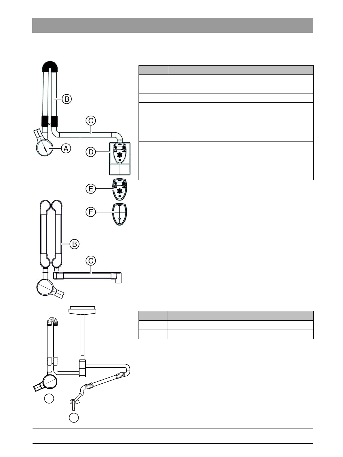
The HELIODENT Plus is available with a round and angular support arm
system.
In the images which do not exclusively demonstrate the angular support
arm system, the round support arm system is shown.
14 D3507.076.01.13.02 10.2016
62 15 102 D3507
Page 15
Sirona Dental Systems GmbH 1General information
A
B
Service Manual HELIODENT
PLUS
1.9The most important subassemblies
1.9
The most important subassemblies
Position Designation
A X-ray tube unit
B Scissor arm
C Support arm
D Wall module
● Board DX1
● Front panel
● Control board DX4
E Remote Timer (Optional)
● Front panel
● Control board DX4
F Remote control (optional)
bеЦдблЬ
Position Designation
A X-ray tube assembly on overhead support
B LEDview on overhead support
62 15 102 D3507
D3507.076.01.13.02 10.2016
15
Page 16
1General information Sirona Dental Systems GmbH
B
C
D
E
F
A
G
C
B
G
1.9The most important subassemblies Service Manual HELIODENT
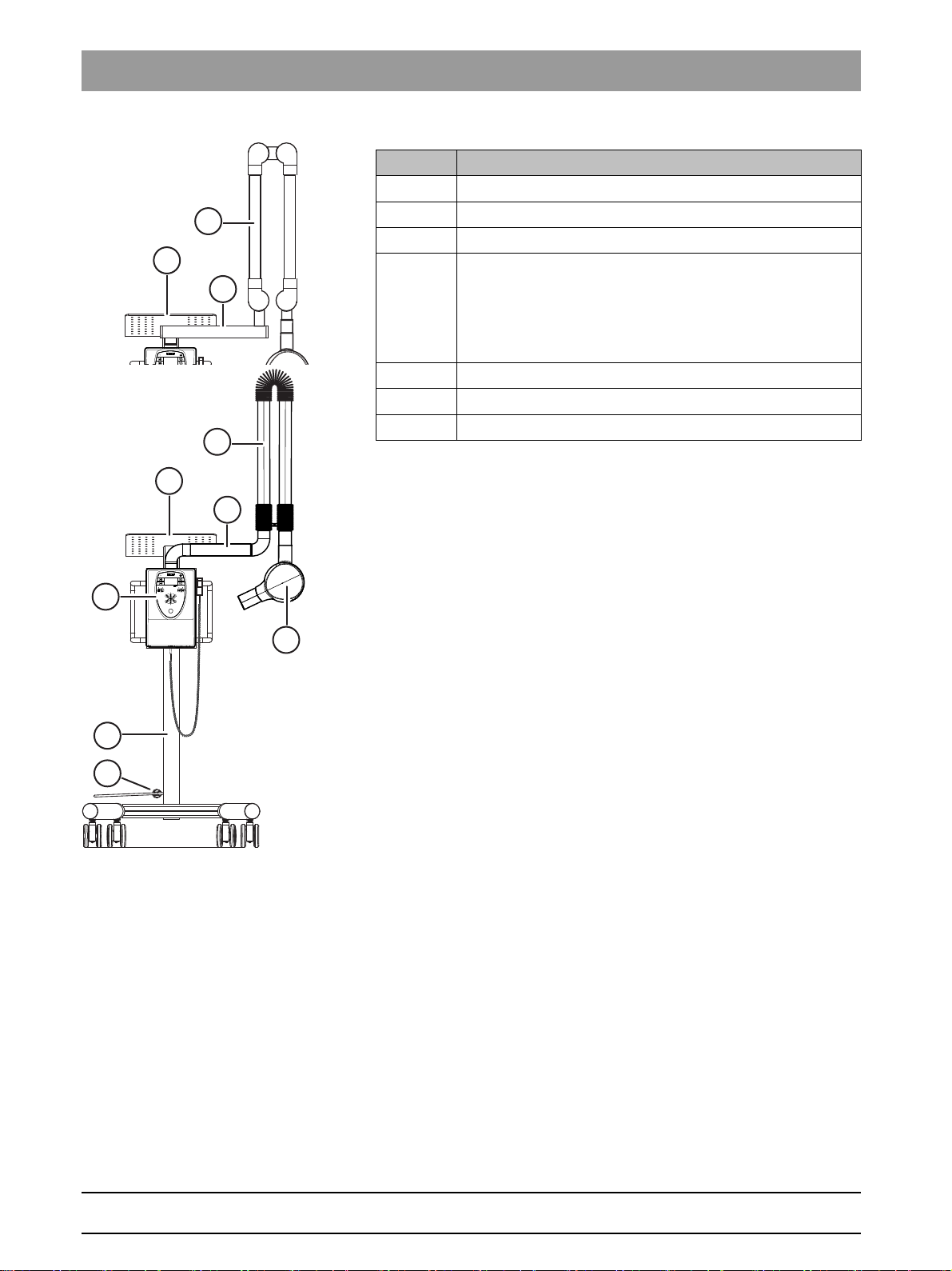
Position Designation
A X-ray tube unit
B Scissor arm
C 410 mm support arm
D Wall module
● Board DX1
● Front panel
● Control board DX4
E Mobile stand
F Power supply cord
GTray
PLUS
16 D3507.076.01.13.02 10.2016
62 15 102 D3507
Page 17
Sirona Dental Systems GmbH 1General information
Service Manual HELIODENT
PLUS
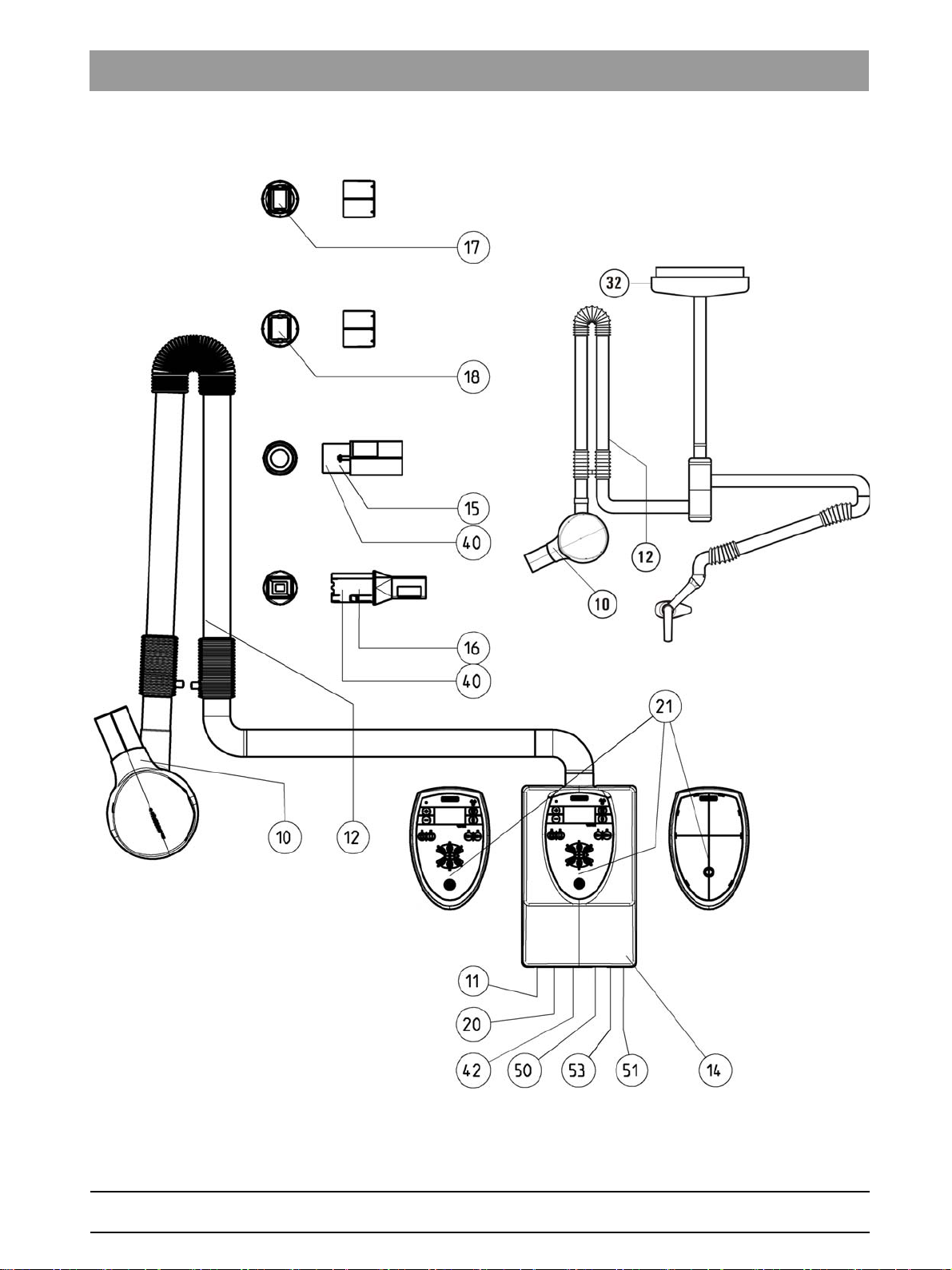
1.10Labeling
1.10
Labeling
bеЦдблЬ
62 15 102 D3507
D3507.076.01.13.02 10.2016
17
Page 18
1General information Sirona Dental Systems GmbH
1.10Labeling Service Manual HELIODENT
PLUS
Item Designation Info
10 ID label of X-ray tube assembly attached inside the cone
11 ID label of wall adapter
12 ID label of scissor arm
14 "Follow the operating instructions" label
15 ID label of round cone extension transp. / white print
16 ID label of square cone extension transp. / white print
17 ID label of radiation field limiter 2x3
18 ID label of radiation field limiter 3x4
20 Warning label for HELIODENT PLUS yellow / black print
21 Warning label for X-ray unit Affixed on site
32 ID label of LEDview
40 DHHS label about Regulations 21CFR (45x27) transp. / white print
42 DHHS label UL-CSA white / black print
50 Chinese label for HELIODENT PLUS
51 Chinese label for HELIODENT PLUS (ID)
53 Chinese label for CCIB
18 D3507.076.01.13.02 10.2016
62 15 102 D3507
Page 19
Sirona Dental Systems GmbH 1General information
B
A
C
S
B
Service Manual HELIODENT
PLUS
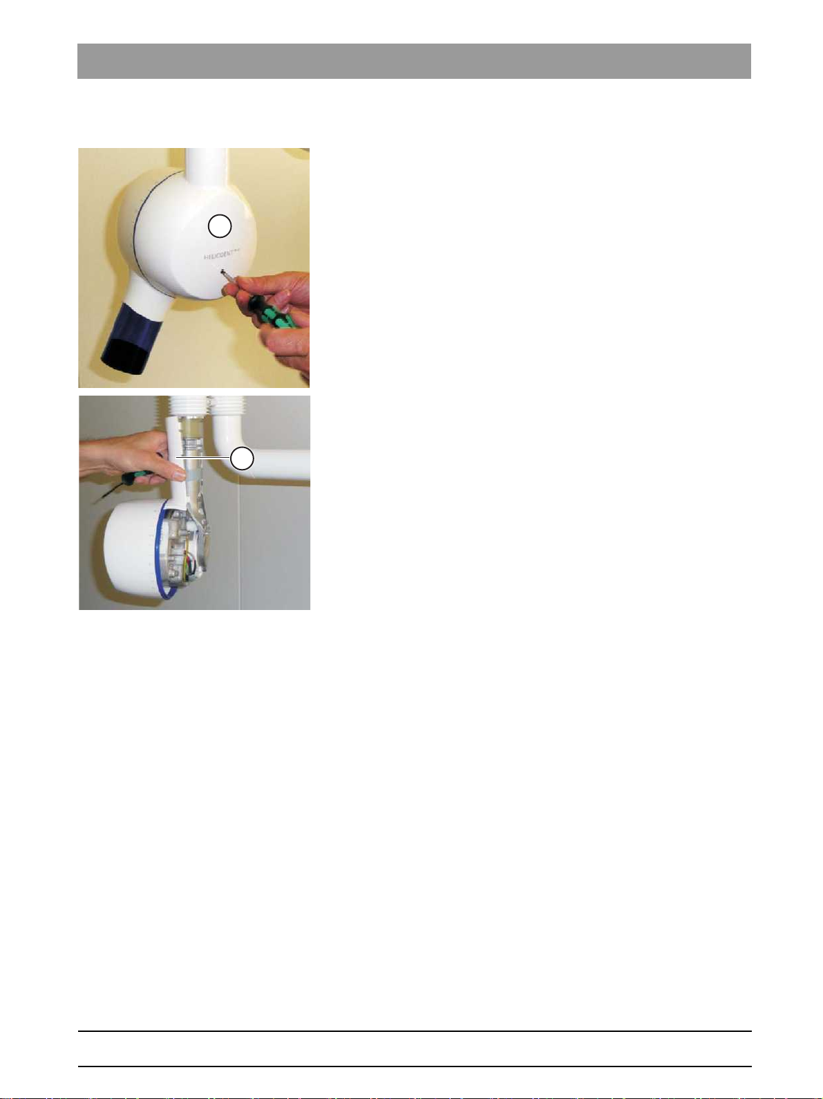
1.11Removing covers
1.11
Removing covers
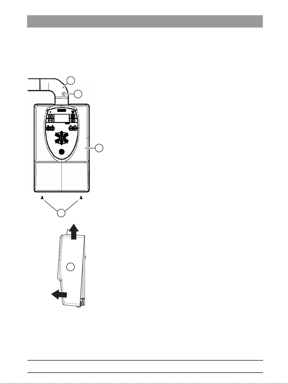
1.11.1 Wall module
Removing the cover
1. Turn the unit off.
2. Unlock the housing shell (C) of the support arm above the wall
module by pinching the housing shells together at position (S).
3. Remove the housing shell (C) from the support arm.
4. Unscrew and remove the fastening screws (A) from the underside.
bеЦдблЬ
5. Pull the protective cover (B) slightly away from the wall and lift it up.
ª You can now remove the protective cover.
62 15 102 D3507
D3507.076.01.13.02 10.2016
19
Page 20
1General information Sirona Dental Systems GmbH
1.11Removing covers Service Manual HELIODENT
PLUS
Hanging up the cover
➢ Hang the cover on the side of the wall adapter plate so that it is
securely positioned (see illustration). To do this from serial no. 27 000
onwards, the EMC plate must be removed beforehand.
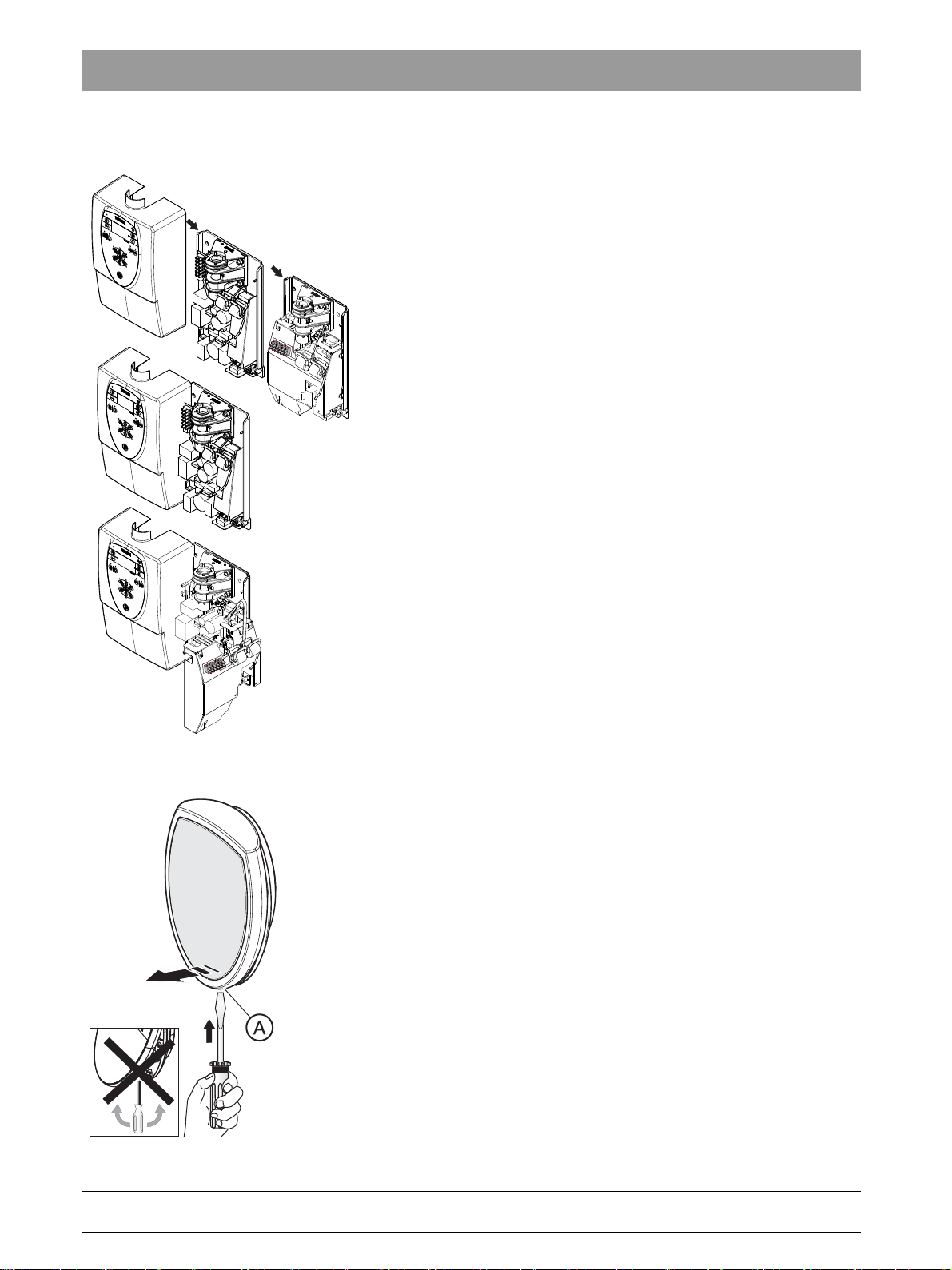
1.11.2 Remote control and remote timer
Open remote
➢ Detach the housing of the remote control or the Remote Timer by
carefully inserting the tip of a screwdriver in opening A and pressing
against the catch. Do not pry with or turn the screwdriver!
62 15 102 D3507
20 D3507.076.01.13.02 10.2016
Page 21
Sirona Dental Systems GmbH 1General information
A
L
Service Manual HELIODENT
PLUS
1.11Removing covers
1.11.3 X-ray tube unit
1. Unscrew and remove the cover (A).
2. Remove the arm cover (L).
bеЦдблЬ
62 15 102 D3507
D3507.076.01.13.02 10.2016
21
Page 22
1General information Sirona Dental Systems GmbH
X400 V413V316
V503
GY/BN
YE WH
GN
F201
X600
F200
X401
V414
PK
BU
PE
X500
X501
X200
V409 D500
F300
V611
N´
N
PE
L1
S1
X400 V413V316
V503
GY/BN
YE WH
GN
F201
X600
F200
X401
V414
PK
BU
X500
X200
V409
D500
F300
V611
N´
N
PE
L1
S1
X501
1.12Overview of PC boards Service Manual HELIODENT
PLUS
1.12
Overview of PC boards
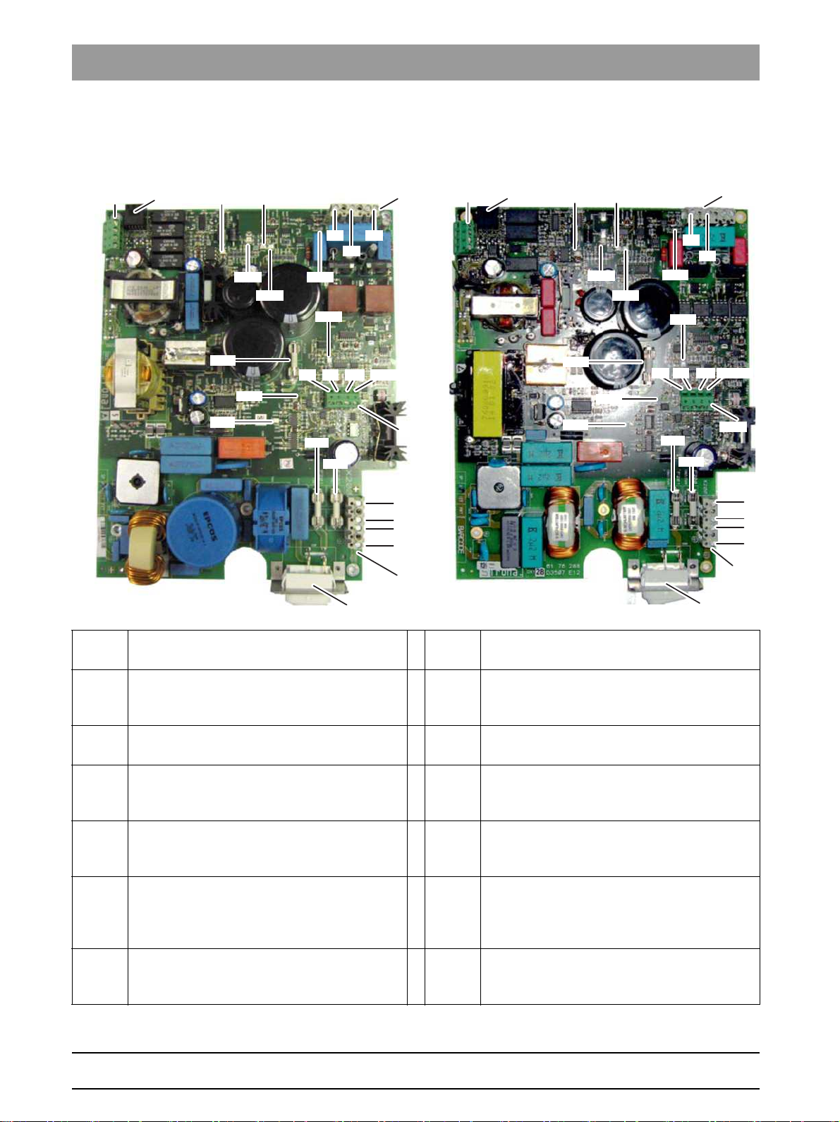
1.12.1 Generator board DX1
S1 Power switch F200 /
F201
F300 Fuse for switched-mode power supply
X400 Direct contact with control board DX4 [ → 23] /
V409 LED, setpoint generation
(1A 250V quick-blow, order no.: 10 77 304)
cable L2 or L6.
- LED lights up during an X-ray exposure.
V414 LED, kV controller
V316 LED, supply voltage +15V
X401 Release and safety circuit only for installation
V413 LED, basic heating
V503 LED, kVactual cable
- LED lights up during an X-ray exposure if the
kV controller is functioning correctly.
D500 Glow lamp, output stage
- The glow lamp lights up during an X-ray
exposure. The high-voltage transformer is
activated.
V611 LED, release
- LED lights up when the release button is
X600 Measuring points for the tube current
Fuse for PFC
(10A 250V slow-blow, order no.: 10 77 460)
- LED lights up when +15 V supply voltage is
present.
options 1, 2, 4, 6, and 6.1
- LED lights up when basic heating is correct.
- LED lights up during an X-ray exposure.
- LED lights up if the kVactual cable is
incorrectly connected.
measurement (see section “Checking the tube
current [ → 60]”).
pressed.
22 D3507.076.01.13.02 10.2016
62 15 102 D3507
Page 23
Sirona Dental Systems GmbH 1General information
Service Manual HELIODENT
PLUS
1.12Overview of PC boards
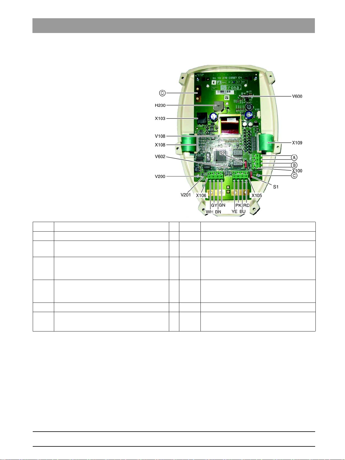
1.12.2 Control board DX4
(A) Protective circuit (door contact) (B) Release button
(C) EMC shielding V108 LED, +3.3 V for LCD
V200 LED, Debugging V201 LED, status indicator
- LED flashes with 100% unit function.
H200 Acoustic signal
- Acoustic signal sounds during an X-ray
exposure.
X103 Direct contact with generator board DX1
[ → 22] / cable L2
(installation options 1, 2, 4, 6 and 6.1)
V600 LED, +8V input voltage V602 LED, +3.3 V controller voltage
X100 Remote timer connection outside the X-ray
room
X108,
X109
X105,
X106
S1
S2
Connection to membrane keyboard
Direct contact with generator board DX1
[ → 22] as remote control / cable L6
(installation options 3, 5, 7 and 8)
Changeover switch, internal/external trigger
Changeover switch, safety circuit ON/OFF
bеЦдблЬ
62 15 102 D3507
D3507.076.01.13.02 10.2016
23
Page 24
1General information Sirona Dental Systems GmbH
1.13Required items Service Manual HELIODENT
PLUS
1.13
Required items
1.13.1 Additional documents
● Spare parts list
– Order No.: 62 34 111
● Wiring diagrams
– Order No.: 62 15 086
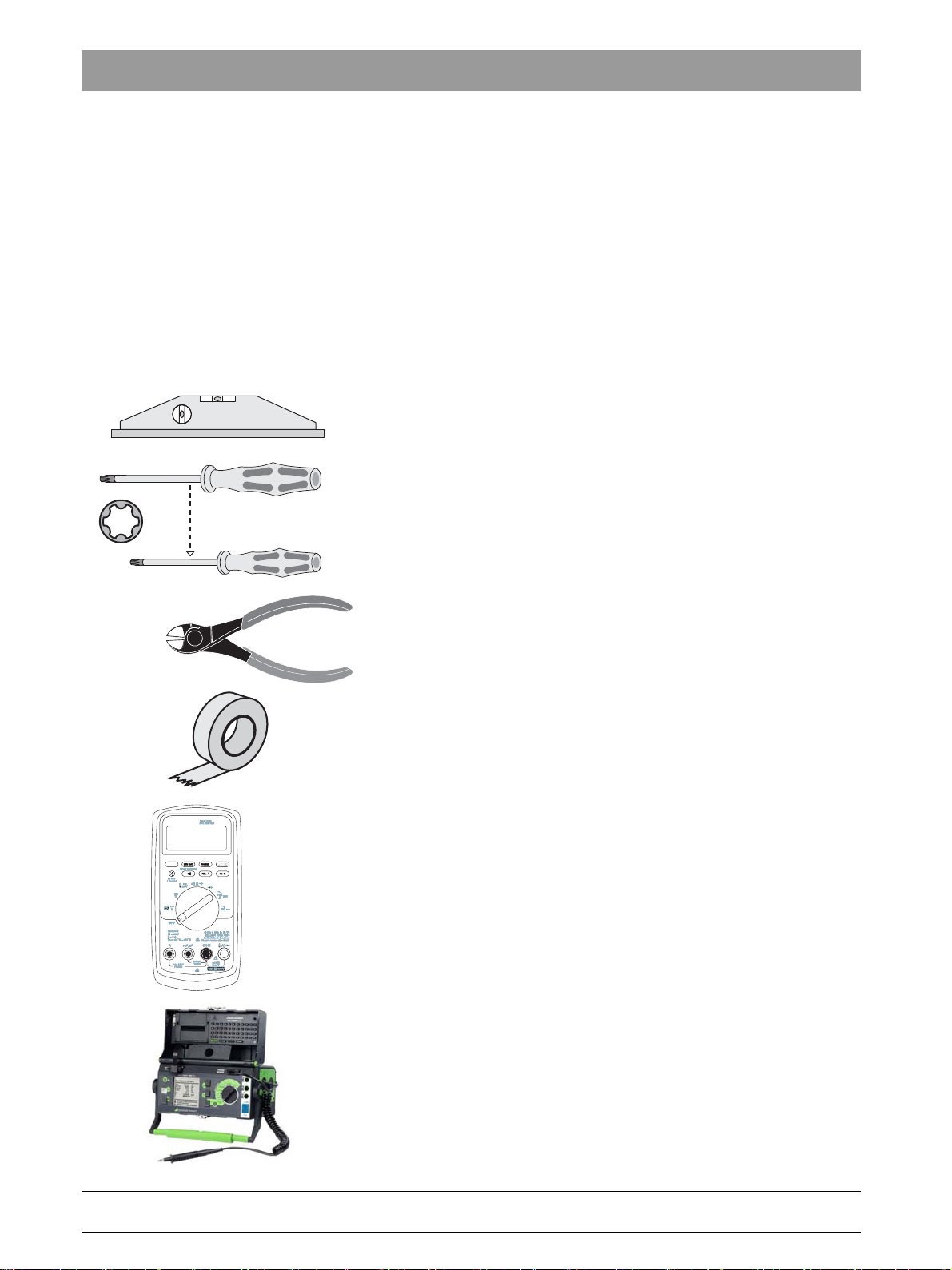
1.13.2 Tools and auxiliary materials
Allen key / size 13:
● Allen key / size 13:
Spirit level (general purp ose)
● Spirit level
● Screwdriver, Torx
Side cutting pliers
● Side cutting pliers
General purpose adhesi ve tape
®
, sizes T10, T15, T20 and T30, 200 mm
● adhesive tape
● 2x multimeter or one of each of the following measuring instruments:
– 1x voltmeter
– 1x ammeter
Device leakage current
● Test unit for device leakage current measurement:
For measurements, Sirona recommends an automatic tester
(example illustration) which complies with standard IEC 62353.
If you do not use an automatic tester, please pay attention to the
specifications in the standard IEC 62353.
Power source
● Power source for protective ground wire test
Technical data:
– No-load voltage max. 6V
– Short-circuit current at least 5A - max. 25A
24 D3507.076.01.13.02 10.2016
62 15 102 D3507
Page 25

Sirona Dental Systems GmbH 2List of messages
Service Manual HELIODENT
PLUS
List of messages
2
2.1Error messages
2.1
Error messages
2.1.1 General
Explanation
The error messages appear on the display of the control electronics.
Recognition
Error messages can be recognized by a six-digit error code (Ex yy zz)
beginning with a large E.
The structure of the error messages is explained in the section entitled
"Structure [ → 25]".
Handling error messages
As a general rule, error messages are acknowledged via all buttons
except for the release button.
If trouble-free operation is possible after the error is acknowledged, then
no further action is necessary.
If error messages reoccur or occur frequently or trouble-free operation is
not possible, identify the error as described in the section "List of error
messages [ → 26]" and take appropriate action to eliminate the
corresponding error or fault.
bеЦдблЬ
2.1.2 Structure
Explanation
The codes provide you with error type, error location and troubleshooting
information. Plain text error output follows.
Configuration
The error codes are structured according to the following pattern: Ex yy zz
Explanation of abbreviations:
Ex – Error type
"Remedy" classification for the user. The x character provides a
foundation for making quick decisions as to how serious the error is and
how to handle the error.
yy – Locality
Describes the impacted functionality.
This functionality can be:
● Subassembly
● Subsystem
● Logical functional unit
zz – Identification
Describes a further specification of the error via a consecutive number
with error identification.
62 15 102 D3507
D3507.076.01.13.02 10.2016
25
Page 26
2List of messages Sirona Dental Systems GmbH
2.1Error messages Service Manual HELIODENT
PLUS
2.1.3 List of error messages
Error code Description Actions required
None Release does not result in any reaction/
exposure
E1 11 88 Demo mode ACTIVE Acknowledge the error message with any
E1 04 03 Acknowledge the error message with any
E1 04 04 Error programming the values. Acknowledge the error message with any
E1 04 60 Error of serial port Replace DX4.
E3 04 30 Power-up error
See Section
"Error message NONE [ → 29]
key.
For "normal operation" - change service
routine 26 [ → 77]
key.
If the error message reappears, DX4 must
be replaced.
key.
If the error message reappears, DX4 must
be replaced.
Switch unit OFF and ON again
Release button was actuated during power-on
E3 04 31 Error keys
A front panel key was actuated during power-on
E5 01 02
E5 01 12
No target values are generated
DX4 buzzer sounds, no exposure
E5 01 14
E5 01 32
E5 01 42
E5 01 02
E5 01 12
Buzzer sounds
No exposure
E5 01 14
If the error message reappears, remove
the release button.
If there are no more error messages, use a
new release button.
If the error message persists, check the
cable between DX1 and DX4. DX4 may
need to be replaced
Switch unit OFF and ON again
If the error reoccurs, perform a key test with
Service routine S22 [ → 75].
Key defective? Replace front panel
Check the cable between DX1 and DX4
(B4). Replace the entire cable if necessary.
If the error message reappears, DX1 must
be replaced.
Replace DX1
E5 01 32
E5 01 02
E5 01 12
Buzzer sounds
No exposure
See Section
""Error message E5 01 02 / E5 01 12 / E5
01 14 [ → 32]"
E5 01 14
26 D3507.076.01.13.02 10.2016
62 15 102 D3507
Page 27
Sirona Dental Systems GmbH 2List of messages
Service Manual HELIODENT
Error code Description Actions required
E5 01 02
PLUS
Buzzer sounds
2.1Error messages
Replace DX1
E5 01 14
E7 01 51
E5 01 22 Buzzer does not sound
E5 04 50 Internal software error Switch unit OFF and ON again
E6 01 13 Internal hardware error Replace DX1.
E6 01 31 Internal hardware error Replace DX1
E6 01 41 Buzzer sounds although the release was not
E6 01 23 Cable is incorrectly attached or internal
E6 01 11 Internal hardware error Replace DX1
E6 01 61 Error diagnosis not working Check the cable between DX1 and DX4.
E6 01 62 Error diagnosis not working Check the cable between DX1 and DX4.
no exposure temporarily
No exposure
actuated
hardware error
See Section
""Error message E5 01 22 [ → 33]"
Repeat the exposure with the same values
If the error message reappears, DX4 must
be replaced.
Switch unit OFF and ON again
If the error message reappears, DX4 must
be replaced
If the error message reappears, DX1 must
be replaced
See Section
""Error message E6 01 23 [ → 34]"
Cable may need to be replaced
Cable may need to be replaced
bеЦдблЬ
If the error message reappears, DX1 must
be replaced
E6 04 01 Internal hardware error Switch unit OFF and ON again
If the error message reappears, DX4 must
be replaced
E6 04 02 Internal error Switch unit OFF and ON again
If the error message reappears, DX4 must
be replaced
E6 04 11 Internal error Replace DX4
E6 04 40 LCD is somewhat darker in some cases Replace DX4
E6 04 41 Power supply of DX4 is interrupted Switch unit OFF and ON again
If the error message reappears, DX4 must
be replaced
E6 04 42 Power supply of DX4 is interrupted Replace DX4
E6 04 10 Internal error Switch unit OFF and ON again
If the error message reappears, DX4 must
be replaced
62 15 102 D3507
D3507.076.01.13.02 10.2016
27
Page 28
2List of messages Sirona Dental Systems GmbH
2.1Error messages Service Manual HELIODENT
PLUS
Error code Description Actions required
E6 04 06 Internal error Switch unit OFF and ON again
If the error message reappears, DX4 must
be replaced
E6 04 12 Internal error Switch unit OFF and ON again
If the error message reappears, DX4 must
be replaced
E6 04 20 Internal error Switch unit OFF and ON again
If the error message reappears, DX4 must
be replaced
E6 04 21 Internal error Switch unit OFF and ON again
If the error message reappears, DX4 must
be replaced
E7 01 01 Cable is incorrectly attached or internal
hardware error
E7 01 21 Release actuated
See Section
""Error message E7 01 01 [ → 36]"
Check the cable between DX1 and DX4.
No buzzer sound
Cable may need to be replaced
No exposure
E7 01 51 Internal hardware error Switch unit OFF and ON again
If the error message reappears, DX1 must
be replaced
E7 04 51 Safety circuit (door contact) Go to section
“Error message: E7 04 51 - Door contact
error [ → 38]”
28 D3507.076.01.13.02 10.2016
62 15 102 D3507
Page 29

Sirona Dental Systems GmbH 3Troubleshooting
Service Manual HELIODENT
PLUS
Troubleshooting
3
3.1Error message: NONE
3.1
Error message: NONE
bеЦдблЬ
62 15 102 D3507
D3507.076.01.13.02 10.2016
29
Page 30

3Troubleshooting Sirona Dental Systems GmbH
3.1Error message: NONE Service Manual HELIODENT
PLUS
30 D3507.076.01.13.02 10.2016
62 15 102 D3507
Page 31

Sirona Dental Systems GmbH 3Troubleshooting
Service Manual HELIODENT
PLUS
3.1Error message: NONE
bеЦдблЬ
62 15 102 D3507
D3507.076.01.13.02 10.2016
31
Page 32

3Troubleshooting Sirona Dental Systems GmbH
3.2Error message: E5 01 02 / E5 01 14 / E5 01 12 Service Manual HELIODENT
PLUS
3.2
Error message: E5 01 02 / E5 01 14 / E5 01 12
32 D3507.076.01.13.02 10.2016
62 15 102 D3507
Page 33

Sirona Dental Systems GmbH 3Troubleshooting
Service Manual HELIODENT
PLUS
3.3Error message: E5 01 22
3.3
Error message: E5 01 22
bеЦдблЬ
62 15 102 D3507
D3507.076.01.13.02 10.2016
33
Page 34

3Troubleshooting Sirona Dental Systems GmbH
3.4Error message: E6 01 23 Service Manual HELIODENT
PLUS
3.4
Error message: E6 01 23
34 D3507.076.01.13.02 10.2016
62 15 102 D3507
Page 35

Sirona Dental Systems GmbH 3Troubleshooting
Service Manual HELIODENT
PLUS
3.4Error message: E6 01 23
bеЦдблЬ
62 15 102 D3507
D3507.076.01.13.02 10.2016
35
Page 36

3Troubleshooting Sirona Dental Systems GmbH
3.5Error message: E7 01 01 Service Manual HELIODENT
PLUS
3.5
Error message: E7 01 01
36 D3507.076.01.13.02 10.2016
62 15 102 D3507
Page 37

Sirona Dental Systems GmbH 3Troubleshooting
Service Manual HELIODENT
PLUS
3.5Error message: E7 01 01
bеЦдблЬ
62 15 102 D3507
D3507.076.01.13.02 10.2016
37
Page 38

3Troubleshooting Sirona Dental Systems GmbH
3.6Error message: E7 04 51 - Door contact error Service Manual HELIODENT
PLUS
3.6
Explanation Depending on the installation type, there are different approaches to
Error correction (case 1) 1. Set switch S2 on PC board DX4 to ON.
Error correction (case 2) 1. Set switch S2 on PC board DX4 to OFF.
Error message: E7 04 51 - Door contact error
address error message E7 04 51.
● Error correction (case 1)
– Installation type "Wall box without door contact"
– Installation type "Remote without door contact"
● Error correction (case 2)
– Installation type "Wall box with door contact"
2. In service routine 015, set the value “1" and save it.
3. Switch the unit off and then on again.
2. In service routine 015, set the value "0" and save it.
3. Switch the unit off and then on again.
38 D3507.076.01.13.02 10.2016
62 15 102 D3507
Page 39

Sirona Dental Systems GmbH 4Maintenance
Service Manual HELIODENT
PLUS
Maintenance
4
4.1Checking the shielding
4.1
Checking the shielding
4.1.1 Test
➢ Check whether the cable shieldings have contact with the shielding
clamps and are firmly in place.
4.1.2 Positions
Installation panel (wall module)
● If available: Manual release S3 on X401
–(B): Clamp
● If available: Cable L2 with ferrite core on X400
bеЦдблЬ
–(C): Clamp
● If available: Cable L6 on X400
–(D): Clamp
62 15 102 D3507
D3507.076.01.13.02 10.2016
39
Page 40

4Maintenance Sirona Dental Systems GmbH
4.1Checking the shielding Service Manual HELIODENT
PLUS
DX4 (wall module)
● X103 / L2 cable (wall mounting)
–(E): Clamp
DX4 (Remote Timer)
● Grounding tab of the front panel
–(F): Screw
● X106/X105 / L6 cable
–(G): Clamp
● X100 / Manual release S3
–(H): Clamp
–(I): Release button
40 D3507.076.01.13.02 10.2016
62 15 102 D3507
Page 41

Sirona Dental Systems GmbH 4Maintenance
Service Manual HELIODENT
PLUS
4.2Checking the protective ground connections
4.2
Checking the protective ground connections
4.2.1 Test
➢ Check whether all protective ground connections are firmly in place.
4.2.2 Positions
DX1 and installation panel (wall module)
● X200 / Power input clamp
● X500* / Output stage and installation panel
bеЦдблЬ
–(A): Screw
* PE is only connected up to serial no. 26 999 on the X500
X-ray tube assembly
● Grounding of the support bracket
–(J): Screw
62 15 102 D3507
D3507.076.01.13.02 10.2016
41
Page 42

4Maintenance Sirona Dental Systems GmbH
4.2Checking the protective ground connections Service Manual HELIODENT
PLUS
● Grounding of the X-ray tube assembly
–(K): Screw
42 D3507.076.01.13.02 10.2016
62 15 102 D3507
Page 43

Sirona Dental Systems GmbH 4Maintenance
Service Manual HELIODENT
PLUS
4.3Checking exposure time and high voltage kV
4.3
Checking exposure time and high voltage kV
Auxiliary devices required
● Suitable radiation meter.
Examples:
– Mini-X
– PMX I-D
–MOM
Preparation
bеЦдблЬ
62 15 102 D3507
D3507.076.01.13.02 10.2016
1. Switch the X-ray unit on.
2. Wait until the self-test is finished (operational readiness signal must
be lit). The display reading shows the radiation time and a patient
symbol).
3. Set an exposure time between 0.25 and 0.4 seconds. The display of
control board DX4 must be clearly visible
4. Position the measuring instrument (B) in such a way that the active
sensor measuring surface has a distance of 50 cm (19.7") from the
focus (A) of the X-ray tube assembly.
5. Switch on the measuring instrument.
43
Page 44

4Maintenance Sirona Dental Systems GmbH
4.4Checking the deadman function Service Manual HELIODENT
PLUS
test
WARNING
X-ray radiation!
➢ Release an exposure with the release button.
● The buzzer must be audible during radiation release.
● The radiation indicator lights up.
– The radiation LED lights up yellow.
– The display background lights up yellow.
➢ Check the measures exposure time and the high voltage measured
at the measuring instrument.
Tolerance: The permitted tolerance of the exposure time and high voltage
is ±10%.
In case of error
● Radiation time outside of tolerance limits
4.4
– Replace board DX4.
● High voltage outside of tolerance limits
– Replace DX1.
Checking the deadman function
test
1. Set the radiation time to 3.2 seconds (display: "3.20 s").
WARNING
X-ray radiation!
2. Release an exposure with the release button and let go of the release
button prior to the end of the radiation.
ª The radiation must stop.
ª The actual radiation time must be shown as a flashing display.
In case of an error
The unit does not stop releasing radiation.
➢ Replace board DX4.
44 D3507.076.01.13.02 10.2016
62 15 102 D3507
Page 45

Sirona Dental Systems GmbH 4Maintenance
Service Manual HELIODENT
PLUS
4.5Checking the release button
4.5
Checking the release button
4.5.1 General
Explanation
Depending on the installation type, there are different descriptions for
checking the release button.
Overview
● Release button on PC board DX1 (coiled cable) [ → 45]
● Release button on PC board DX4 (coiled cable) [ → 46]
● Release button on front panel on PC board DX4 [ → 47]
4.5.2 Release button on PC board DX1 (coiled cable)
NOTICE
Only one release button may be connected (active)!
Preparation
1. Switch the unit off.
2. Connect the measuring instrument:
bеЦдблЬ
● With installed door contact
– Connect the measuring instrument to DX1 X401.1 and X401.2.
● With no installed door contact
– Connect the measuring instrument to DX1 X401.1 and X401.4.
test
➢ Check the following points:
● Is the strain relief of the coiled cable fully functional?
● Is the release button easy to actuate?
● Does the release button return to its home position on its own after
letting go?
● With release button not pressed: Measured resistance exceeds
100k Ω .
● With release button pressed: Measured resistance is below 100 Ω .
● Do the measured resistance values remain constant when the coiled
cable is moved?
➢ After the test: Remove the measuring instrument.
In case of an error
62 15 102 D3507
D3507.076.01.13.02 10.2016
➢ Replace the release button with coiled cable.
45
Page 46

4Maintenance Sirona Dental Systems GmbH
4.5Checking the release button Service Manual HELIODENT
PLUS
4.5.3 Release button on PC board DX4 (coiled cable)
NOTICE
Only one release button may be connected (active)!
Preparation
1. Switch the unit off.
2. Connect the measuring instrument:
● With installed door contact
– Connect the measuring instrument to DX4 X100.1 and X100.2.
● With no installed door contact
– Connect the measuring instrument to DX4 X100.1 and X100.4.
test
➢ Check the following points:
● Is the strain relief of the coiled cable fully functional?
● Is the release button easy to actuate?
● Does the release button return to its home position on its own after
letting go?
● With release button not pressed: Measured resistance exceeds
100k Ω .
● With release button pressed: Measured resistance is below 100 Ω .
● Do the measured resistance values remain constant when the coiled
cable is moved?
➢ After the test: Remove the measuring instrument.
In case of an error
➢ Replace the release button with coiled cable.
46 D3507.076.01.13.02 10.2016
62 15 102 D3507
Page 47

Sirona Dental Systems GmbH 4Maintenance
Service Manual HELIODENT
PLUS
4.5Checking the release button
4.5.4 Release button on front panel on PC board DX4
NOTICE
Only one release button may be connected (active)!
Preparation
1. Switch the unit off.
2. Connect the measuring instrument to DX1 X401.1 and X401.3.
test
➢ Check the following points:
● Is the release button easy to actuate?
● Does the release button return to its home position on its own after
letting go?
● With release button not pressed: Measured resistance exceeds 1k Ω .
● With release button pressed: Measured resistance is below 100 Ω .
➢ After the test: Remove the measuring instrument.
In case of an error
➢ Replace the front panel.
bеЦдблЬ
62 15 102 D3507
D3507.076.01.13.02 10.2016
47
Page 48

4Maintenance Sirona Dental Systems GmbH
D
C
B
A
S22
4.6Checking the front panel Service Manual HELIODENT
PLUS
4.6
Checking the front panel
CAUTION
Defective indicators and keys represent a risk to the safety of both the
patient and the operator/user.
The user is not permitted to operate the unit until the necessary repairs
have been made.
4.6.1 Visual check
Check
Visually check the front panel for external damage.
● Is the front panel of the user interface undamaged?
● Is the surface panel free of cracks or holes?
NOTICE
The transparent front panel over the light diodes must not be punctured,
otherwise there is a risk of ESD damage.
4.6.2 Front panel test
Explanation
In the front panel test, you can check the function of every individual key
on the front panel.
Command
➢ Open service routine S22 (see "Operation [ → 65]" in the Section
"Service routines").
Operation
➢ Actuate every key in sequence.
ª A code is indicated in a certain area on the display each time a key is
actuated.
Areas
48 D3507.076.01.13.02 10.2016
62 15 102 D3507
Page 49

Sirona Dental Systems GmbH 4Maintenance
+
_
60kV
70kV
Service Manual HELIODENT
PLUS
4.6Checking the front panel
Code table
Key Area Code Key Area Code
A1 B32
A2 B64
A4 B128
A8 C1
B2 C2
B4 C4
B8 C8
B16 D1
bеЦдблЬ
62 15 102 D3507
D3507.076.01.13.02 10.2016
49
Page 50

4Maintenance Sirona Dental Systems GmbH
4.7Checking and adjusting the support arm Service Manual HELIODENT
PLUS
4.7
Checking and adjusting the support arm
CAUTION
Switch OFF the unit before connecting a measuring instrument or
replacing parts!
4.7.1 Round support arm system
Check
● Are all bellows intact?
– If the bellows are damaged, the support arm must be replaced.
See section “Replacing the support arm”.
● Does the X-ray tube assembly drift from its work position on its own?
– If the X-ray tube assembly drifts, the support arm must be
readjusted.
Setting
Adjusting the spring on the scissor arm (support arm side)
1. Invert the bellows over the half-shells (A) on both sides.
2. Pull off the half-shells.
3. Pull the scissor arm apart and slide the bellows over the bearing.
4. Set both support arms in vertical position.
5. Insert the Torx screwdriver (T30, 200 mm) into the drilling of the
bearing from the top and adjust the spring (right turn = tighter).
6. Reassemble the support arm by completing the same steps in
reverse order.
Adjusting the spring on the scissor arm (X-ray tube assembly side)
1. Invert the bellows over the upper half-shell (A).
2. Press the bellows downward.
3. Set the support arm into a horizontal position.
4. Insert the Torx screwdriver (T30, 200 mm) into the drilling of the
bearing from the front and adjust the spring (right turn = tighter).
5. Reassemble the support arm by completing the same steps in
reverse order.
62 15 102 D3507
50 D3507.076.01.13.02 10.2016
Page 51

Sirona Dental Systems GmbH 4Maintenance
A
B
Service Manual HELIODENT
PLUS
4.7Checking and adjusting the support arm
4.7.2 Angular support arm system
Risk of crushing
CAUTION
Gaps appear between the internal hinges when moving the angular
support arm.
Fingers may be crushed in these gaps.
➢ Ensure that you never place your fingers in the gaps between the
hinges, neither during operation nor for cleaning purposes.
4.7.2.1
Checking and adjusting the angular scissor arm
Check
● Does the X-ray tube assembly drift from its work position on its own?
– If the X-ray tube assembly drifts, the support arm must be
readjusted.
Setting
Adjusting the spring on the scissor arm (support arm side)
1. Remove the cover part (B).
2. Place the rear scissor arm in a vertical position.
3. Insert the Allen key (SW6, 200 mm) into the bearing hole from above
and adjust the spring (right turn = tighter).
bеЦдблЬ
62 15 102 D3507
D3507.076.01.13.02 10.2016
51
Page 52

4Maintenance Sirona Dental Systems GmbH
A
B
A
B
4.7Checking and adjusting the support arm Service Manual HELIODENT
Adjusting the spring on the scissor arm (X-ray tube assembly side)
1. Remove the cover part (A).
2. Bring the front scissor arm into a horizontal position.
3. Insert the Allen key (SW6, 200 mm) into the bearing hole from the
front and adjust the spring (right turn = tighter).
4. Reattach the cover parts.
PLUS
4.7.2.2
Checking and adjusting the angular scissor arm is parallel
Check
● Is the boom of the scissor arm not parallel with the scissor arm?
– If a lateral or height offset is needed there, the scissor arm must
be recalibrated.
Setting
1. Remove the cover parts (A+B).
2. Release the internal locking pins on all 4 bolts using the Allen key
(SW-3).
62 15 102 D3507
52 D3507.076.01.13.02 10.2016
Page 53

Sirona Dental Systems GmbH 4Maintenance
Service Manual HELIODENT
PLUS
4.7Checking and adjusting the support arm
3. Release the bolts slightly with the ring wrench (SW-13).
4. Open the locking pins on 2 joints slightly (SW-1,5).
5. Place both scissor arms in a vertical position.
Check the alignment
6. Set parallelism using the eccentric bolts.
7. Reassemble the support arm by completing the same steps in
reverse order.
8. Reattach the cover parts.
bеЦдблЬ
62 15 102 D3507
D3507.076.01.13.02 10.2016
53
Page 54

4Maintenance Sirona Dental Systems GmbH
A
L
4.8Checking the X-ray tube assembly joint Service Manual HELIODENT
PLUS
4.8
Checking the X-ray tube assembly joint
CAUTION
Switch OFF the unit before connecting a measuring instrument or
replacing parts!
Required tools
Torx screwdriver (size 10, 15 and 20)
Check
● Does the cone remain set in every position?
● Are the connecting cables intact?
– See section on "Checking the connection cables".
If the X-ray tube assembly fails any of these check points, it must be
replaced (see Section "Replacing X-ray tube assembly H1 [ → 79]").
Checking the connection cables
1. Switch the X-ray unit off.
2. Unscrew and remove the old cover (A).
3. Remove the arm cover (L).
54 D3507.076.01.13.02 10.2016
62 15 102 D3507
Page 55

Sirona Dental Systems GmbH 4Maintenance
K
B
Service Manual HELIODENT
PLUS
4.8Checking the X-ray tube assembly joint
4. Check the condition of the grounding strap.
ª No damage should be evident at position (K). Slight restriction at
the position (K) of up to 20% cross-section loss is acceptable.
5. Check the screw terminal on the grounding wire (B) for damage.
6. Check the plug contacts on the connector (X1) for damage.
bеЦдблЬ
62 15 102 D3507
D3507.076.01.13.02 10.2016
55
Page 56

4Maintenance Sirona Dental Systems GmbH
J
L
A
4.8Checking the X-ray tube assembly joint Service Manual HELIODENT
7. Check the scissor arm (J) to make sure it does not brush against a
cable when moved.
ª No cable should touch the scissor arm in any position. Fasten the
cable with a cable tie if necessary.
8. Attach the arm cover (L).
PLUS
9. Attach and secure the cover (A).
56 D3507.076.01.13.02 10.2016
62 15 102 D3507
Page 57

Sirona Dental Systems GmbH 4Maintenance
67
8
9
SXL
X4
X1
X2
B
A
KL 10
NL
88NNLL7
765 4321
65 432 1
L8
L7
Kl 10
67
8
9
X4
X1
X2
SXL
D
C
Service Manual HELIODENT
PLUS
4.9Checking the ceiling model
4.9
Checking the ceiling model
Check the overhead support
● Is the cover (A) fastening in safe condition?
● Are the cover parts (B) present and free of damage?
bеЦдблЬ
● Is the protective ground connection securely (C) positioned?
● Damage-free, tight and proper seating of the cables on clamp K10 (D)
in the ceiling model?
62 15 102 D3507
D3507.076.01.13.02 10.2016
57
Page 58

4Maintenance Sirona Dental Systems GmbH
X100
4.9Checking the ceiling model Service Manual HELIODENT
PLUS
Check the wall adapter
● Is the protective ground connection securely (F) positioned?
● Damage-free, tight and proper seating of the cables on clamp X100
(E) (X100 is positioned in a different position depending on the serial
number) in the wall adapter?
58 D3507.076.01.13.02 10.2016
62 15 102 D3507
Page 59

Sirona Dental Systems GmbH 4Maintenance
B
A
D
C
X100
Service Manual HELIODENT
PLUS
4.10Checking HELIODENT PLUS on the mobile stand
4.10
Checking HELIODENT PLUS on the mobile stand
Check the mobile stand
● Is the wall module fastening on the mobile stand (A) in a safe
condition?
● Is the power supply cord (C) with strain relief and bend protection on
the mobile stand in order?
● Are the 4 rollers (B) of the mobile stand, including brakes, in order
and free from contamination?
bеЦдблЬ
62 15 102 D3507
D3507.076.01.13.02 10.2016
Check the wall module
● Is the protective ground connection securely (F) positioned?
● Damage-free, tight and proper seating of the cables on clamp X100
(E) (X100 is positioned in a different position depending on the serial
number) in the wall adapter?
● Are the cover parts (D) present and free of damage?
59
Page 60

4Maintenance Sirona Dental Systems GmbH
4.11Checking the tube current Service Manual HELIODENT
PLUS
4.11
Checking the tube current
Auxiliary devices required
● Ammeter
CAUTION
Only use battery-powered measuring devices.
Preparation
1. Switch the unit off.
2. Set the ammeter to the "10 mA DC" measuring range.
3. Connect the ammeter to the two outer X600 connectors on board
DX1.
4. Switch the unit on.
5. Set the radiation time to 3.2 seconds (display: "3.20 s").
test
WARNING
X-ray radiation!
➢ Release an exposure with the release button and read the tube
current from the ammeter.
Tolerance: The tube current must be 7 mA ±1.4 mA.
62 15 102 D3507
60 D3507.076.01.13.02 10.2016
Page 61

Sirona Dental Systems GmbH 4Maintenance
K
Service Manual HELIODENT
PLUS
4.12Checking the protective ground wires
Completion
1. Switch the unit off.
2. Remove the measuring wires of the ammeter from connector X600.
3. Reattach the housing on the wall module.
In case of an error
● The measurement value is not reached.
– Replace the X-ray tube assembly.
4.12
Checking the protective ground wires
Auxiliary devices required
● Power source
Technical data:
– No-load voltage max. 6V.
– Short-circuit current min. 5A - max. 25A
● Ammeter
– Observe the current intensity of the power source
● Voltmeter
Preparation
WARNING
Perilous shock hazard!
Switch the line voltage off.
1. Switch the line voltage off at the main switch of the building
installation.
2. Remove the power cable from connector X200 on PC board DX1.
bеЦдблЬ
62 15 102 D3507
D3507.076.01.13.02 10.2016
Visual check
1. Check the assembly and firm seating of the ground conductor.
2. Check the main fuse (F200, F201).
3. Check the condition of the grounding strap.
ª No damage should be evident at position (K). A slight restriction
at position (K) with a cross-section loss of max. 20% is still
acceptable.
61
Page 62

4Maintenance Sirona Dental Systems GmbH
4.12Checking the protective ground wires Service Manual HELIODENT
PLUS
Protective ground wire test
Explanation
This test checks the electrical resistance of conductive and exposed parts
of the X-ray unit against the protective wire connection.
Test assembly
See drawing.
Test
1. Set the test current for at least 5 seconds between protective wire
connection X200 / PE (board DX1) and ground connection B (X-ray
tube assembly).
2. Read the voltage drop on the voltmeter and the current on the
ammeter.
3. Calculate the protective conductor resistance with the formula "R = U
/ I."
Limit value
The calculated resistance value must not be greater than 0.2 Ω.
62 D3507.076.01.13.02 10.2016
62 15 102 D3507
Page 63

Sirona Dental Systems GmbH 4Maintenance
Service Manual HELIODENT
PLUS
4.13Checking the unit leakage current
4.13
Checking the unit leakage current
DANGER
Perilous shock hazard!
It is essential to switch the unit off and to wait at least one more 1 minute
before beginning the check!
Prevent the device from unintentionally switching back on.
NOTICE
Important information on building installation
The connection and disconnection of the unit (power cable) to/from the
building installation must be performed by a qualified expert in
compliance with the national regulations. DIN VDE 0100-710 applies in
Germany.
Automatic tester in accordance with IEC 62353
For measurements, Sirona recommends an automatic tester (example
illustration) which complies with standard IEC 62353. If you do not use an
automatic tester, please pay attention to the specifications in the standard
IEC 62353.
1. Switch the line voltage off at the main switch of the building
installation.
2. DANGER! Note the electrical safety rules without fail.
Disconnect the power cable and the second protective ground wire
from the building installation.
3. Attach a connector compatible with the tester (see the user’s manual
for the tester) to the unit’s power cable.
4. Plug the connector of your power supply unit into the intended socket
on the tester in accordance with the user’s manual for the tester.
5. Check whether the unit power switch is turned on.
bеЦдблЬ
62 15 102 D3507
D3507.076.01.13.02 10.2016
IMPORTANT
According to Note 2 in Table 3 of standard IEC 62353:2014, the
maximum device leakage current permitted by the manufacturer is 2 mA
for permanently connected units.
6. Perform the measurements according to the operating instructions of
the tester.
7. Document the measured value of the leakage current in the technical
document
to identify changes from the original value.
ª A maximum deviation of ±20% from the original value is
8. Reconnect the unit to the building installation (fixed connection) (see
the installation instructions for the unit).
"Inspection and maintenance and safety-related checks"
permitted for the measured leakage current.
Threshold value of wall-mounted model
The measured value must not exceed 2,0mA.
Threshold value of ceiling-mounted model
The measured value must not exceed 2.0mA.
Threshold value with mobile model
The measured value must not exceed 2.0mA.
63
,
Page 64

4Maintenance Sirona Dental Systems GmbH
X200
4.14Checking insulation resistance on the power supply cord of the mobile stand Service Manual HELIODENT
PLUS
4.14
Checking insulation resistance on the power supply cord of the mobile stand
Auxiliary devices required
● Safety tester for insulation resistance
Preparation
WARNING
Perilous shock hazard!
Switch the line voltage off.
✔ Measure the insulation resistance between each active conductor
and protective ground conductor.
✔ Switch the unit off and unplug the connector from the power socket.
1. To remove the cover, see Removing covers [ → 19].
Elect. connection 1 phase
2. Disconnect the power supply cord from clamp X200 on DX1.
3. Set a test voltage of 500 V on the safety test device and follow the
instructions in the test device's description.
ª The tester displays the insulation resistance of the short-circuited
power supply cords L and N against the protective ground
conductor.
The insulation resistance must be greater than 100 M Ω .
4. Re-connect the power supply cord to clamp X200 on DX1.
L1: brown
N: blue.
PE: green/yellow
5. Insert the connector into the socket, check the functioning of the unit.
Reattach the covers.
64 D3507.076.01.13.02 10.2016
62 15 102 D3507
Page 65

Sirona Dental Systems GmbH 5Service routines
++
+
_
Service Manual HELIODENT
PLUS
Service routines
5
5.1Operation
5.1
Operation
1. Switch the unit on.
2. Press the Film key, the Sensor key and the Bite Wing key
simultaneously.
ª The service routine "S01" is displayed in front of a white
background.
3. Scroll through the list of service routines by pressing the +/- keys.
4. Press the Film key to show the setting of the displayed service routine
and make any changes which then may be necessary.
ª The setting is displayed.
5. To change the setting, press the +/- keys.
6. To save the current service routine, press the Adult key.
7. To discard the settings of the current service routine and quit it, press
the Child key.
8. Finally, switch the unit off and then on again.
bеЦдблЬ
62 15 102 D3507
D3507.076.01.13.02 10.2016
65
Page 66

5Service routines Sirona Dental Systems GmbH
5.2Overview Service Manual HELIODENT
PLUS
5.2
Overview
Service routine Function
S01 Configuration of transparency compensation for
films [ → 67]
S02 Configuration of transparency compensation for
sensors [ → 67]
S03 Display of software version [ → 67]
S04 Selection of film type [ → 67]
S05 Selection of sensor type [ → 68]
S06 Selection of cone type [ → 68]
S07 Set diaphragm type [ → 69]
S08 Configuration of radiation time and dose display
after an X-ray exposure [ → 69]
S09 Configuration of time-out time of the radiation
time and dose display [ → 69]
S10 Configuration of display options: Area dose and
actual radiation time [ → 70]
S11 Configuration of power-save mode [ → 70]
S12 Configuration of time-out time of the power-save
mode [ → 70]
S13 Configuration of 60/70 kV toggle [ → 71]
S14 Configuration of detector medium toggle (film/
sensor) [ → 71]
S15 Configuration of safety circuit bypass [ → 72]
S16 Configuration of the dynamic pulse/pause ratio
(dynamic cooling) [ → 73]
S17 Dose rate correction [ → 73]
S18 Setting the display contrast [ → 74]
S19 Setting the display brightness and color [ → 74]
S20 Setting the LED brightness [ → 75]
S21 Display self-test [ → 75]
S22 Front panel test [ → 75]
S23 Display of the exposure and radiation time
counter [ → 76]
S24 Reading the status log [ → 76]
S25 Display of saved data [ → 76]
S26 Activation of demo mode [ → 77]
S27 Resetting the unit to factory default settings
[ → 77]
S28 Setting the overall X-ray filter strength [ → 78]
S29 Setting the maximum radiation time from 0.4 s -
3.2 s [ → 78]
66 D3507.076.01.13.02 10.2016
62 15 102 D3507
Page 67

Sirona Dental Systems GmbH 5Service routines
Service Manual HELIODENT
PLUS
5.3Service routines (list)
5.3
Service routines (list)
5.3.1 Service routine S01
Explanation
Configuration of transparency compensation for films
Configuration
You can adjust the transparency compensation in the range from -6 to +6
by pressing the +/- keys (factory default setting = "0").
5.3.2 Service routine S02
Explanation
Configuration of transparency compensation for sensors
Configuration
You can adjust the transparency compensation in the range from -6 to +6
with the +/- keys (factory default setting = "0").
5.3.3 Service routine S03
Explanation
bеЦдблЬ
Display of software version
5.3.4 Service routine S04
Explanation
Selection of film type
You can toggle between the following film types:
●FILM D
●FILM E
●FILM F
Operation
Toggle between the film types by pressing the +/- keys.
Legend
Display Film type
FILM D FILM D
FILM E FILM E (factory default setting)
FILM F FILM F
62 15 102 D3507
D3507.076.01.13.02 10.2016
67
Page 68

5Service routines Sirona Dental Systems GmbH
5.3Service routines (list) Service Manual HELIODENT
PLUS
5.3.5 Service routine S05
Explanation
Selection of sensor type
You can toggle between the following sensor types:
● Sirona sensor
● Non-Siemens sensor
● Imaging plate
Operation
Toggle between the sensor types by pressing the +/- keys.
Legend
Display Sensor type
Sirona
General
Scanner
Sirona XIOS/XIOS
(factory default setting)
Non-Siemens sensor
Imaging plate
Plus
sensor
5.3.6 Service routine S06
Explanation
Selection of focus type (cone length)
You can toggle between the following focus types (cone lengths):
● 200 mm (8")
● 300 mm (12")
Operation
Toggle between the focus types by pressing the +/- keys.
Legend
Display
(Focus type)
200mm (8")
300mm (12")
Cone length in mm
200 mm (8") (factory default setting)
300 mm (12")
68 D3507.076.01.13.02 10.2016
62 15 102 D3507
Page 69

Sirona Dental Systems GmbH 5Service routines
Service Manual HELIODENT
PLUS
5.3Service routines (list)
5.3.7 Service routine S07
Explanation
Selection of diaphragm type
Operation
Toggle between the diaphragm types by pressing the +/- keys.
Legend
Display
(Focus type)
Off
2x3cm
3x4cm
5.3.8 Service routine S08
Explanation
Configuration of radiation time and dose display after an X-ray exposure
Operation
Toggle between 0, 1, 2, and 3 by pressing the +/- keys.
Legend
Display Configuration
0 No radiation time and dose indication
1 Display until time-out
2 Display until key actuation
3 Display until time-out or key actuation
Diaphragm type
no diaphragm (factory default setting)
Diaphragm, 2x3cm
Diaphragm, 3x4cm
bеЦдблЬ
(factory default setting)
62 15 102 D3507
D3507.076.01.13.02 10.2016
5.3.9 Service routine S09
Explanation
Configuration of time-out time of the radiation time and dose display
Operation
Set the time-out time to a value from 0 to 255 seconds by pressing the +/
- keys (factory default setting = "10" seconds).
69
Page 70

5Service routines Sirona Dental Systems GmbH
5.3Service routines (list) Service Manual HELIODENT
PLUS
5.3.10 Service routine S10
Explanation
Configuration of display options: Area dose and actual radiation time
This option allows for the display of the area dose and actual radiation
time after an exposure.
Operation
Toggle between Off and On by pressing the +/- keys.
Legend
Display Option
Off
On
deactivated
activated (factory default setting)
5.3.11 Service routine S11
Explanation
Configuration of the power-save mode
Operation
Toggle between Off and On by pressing the +/- keys.
Legend
Display Power-save mode
Off
On
5.3.12 Service routine S12
Explanation
Configuration of time-out time of the power-save mode
You can set the time-out time for changing to power-save mode in
minutes.
Operation
You can adjust the time-out time in minutes with the +/- keys
(factory default setting = "30" minutes).
Inactive
active (factory default setting)
NOTICE
The smallest value is 1 minutes.
62 15 102 D3507
70 D3507.076.01.13.02 10.2016
Page 71

Sirona Dental Systems GmbH 5Service routines
Service Manual HELIODENT
PLUS
5.3Service routines (list)
5.3.13 Service routine S13
Explanation
Configuration of 60/70 kV toggle
You can activate or deactivate the kV toggle with the kV keys "60kV“ and
"70kV.“
Operation
Toggle between Off and On by pressing the +/- keys.
● If the kV toggle is deactivated, the current kV setting will become the
default setting.
● The active kV setting can be selected with the kV keys "60kV" and
"70kV."
Legend
Display kV switching
Off
On
deactivated
activated
(factory default setting with "60kV"
preselected)
bеЦдблЬ
5.3.14 Service routine S14
Explanation
Configuration of detector medium toggle (film/sensor)
You can activate or deactivate the detector medium toggle with the "Film“
and "Sensor.“
Operation
Toggle between Off and On by pressing the +/- keys.
● If the toggle is deactivated, the active detector medium setting will
become the default setting.
● The active detector medium can be selected with the "Film" and
"Sensor" keys.
Legend
Display Change-over
Off
On
deactivated
activated
(factory default setting with "Sensor"
preselected)
62 15 102 D3507
D3507.076.01.13.02 10.2016
71
Page 72

5Service routines Sirona Dental Systems GmbH
intern
extern
ON
OFF
S1
S2
S1
5.3Service routines (list) Service Manual HELIODENT
PLUS
5.3.15 Service routine S15
Explanation
Configuration of the safety circuit bypass.
The safety circuit can be bypassed via hardware on DX4 (slide switch S2)
(See section "Setting switch S1 and S2 on DX4".
● Slide switch S2 "On" = safety circuit bypassed
● Slide switch S2 "Off" = safety circuit activated
If the setting of slide switch S2 is changed, then the setting of service
routine S15 also must be changed.
● If slide switch S2 is set to "On", then "On" also must be activated in
service routine S15.
● If slide switch S2 is set to "Off", then "Off" also must be activated in
service routine S15.
Factory setting
● Slide switch S2 and service routine 15 are set to "On" ex works.
Operation
Toggle between Off and On by pressing the +/- keys.
72 D3507.076.01.13.02 10.2016
62 15 102 D3507
Page 73

Sirona Dental Systems GmbH 5Service routines
Service Manual HELIODENT
PLUS
5.3Service routines (list)
5.3.16 Service routine S16
Explanation
Configuration of the dynamic pulse/pause ratio (dynamic cooling)
Operation
Toggle between Off and On by pressing the +/- keys.
Legend
Display Dynamic cooling
Off
On
deactivated
activated (factory default setting)
5.3.17 Service routine S17
Explanation
Adaptation of the dose rate display to the measured dose rate of an
external measuring instrument.
The nominal value for a radiation time of one second at 60 or 70kV is used
as the basis here.
bеЦдблЬ
NOTICE
If the factory default setting is reset (Service routine S27 [ → 77]), the
adjustment will be deleted.
NOTICE
The measurement should be performed for both voltages (60 and 70
kV).
Operation
1. Measure the dose rate on the external measuring instrument
(measuring range mGy/s) with a radiation time of one second.
2. Start service routine S17.
3. Set the tube voltage used with the kV keys (60kV, 70kV).
ª The nominal values of the dose rate for a radiation time of one
second and of the tube voltage used are displayed in the first line.
4. Set the measured dose rate in the second line by pressing the +/keys.
5. Acknowledge the setting by clicking the Adult key.
62 15 102 D3507
D3507.076.01.13.02 10.2016
73
Page 74

5Service routines Sirona Dental Systems GmbH
5.3Service routines (list) Service Manual HELIODENT
PLUS
5.3.18 Service routine S18
Explanation
Setting the display contrast
You can set the display contrast in the range from 0 to 100%.
Operation
Set the contrast between 0 and 100 (%) by pressing the +/- keys (factory
default setting = "40" (%)).
5.3.19 Service routine S19
Explanation
Setting the display brightness and color
The color and brightness of the display are determined via three
adjustable color light sources.
The combined intensity of these light sources influences the brightness
and color of the display (additive color mixture).
It is thus possible to adapt the display to the color and brightness of the
display of a XIOS
next to each other).
Plus
wall module (if both units are mounted on the wall
Configuration
In one line, the intensities of the three light sources (red, green and blue)
are displayed as numerical values (0 to 255):
● Left numerical value: red light source (factory default setting = "0")
● Center numerical value: green light source (factory default setting =
"165")
● Right numerical value: blue light source (factory default setting =
"255")
The active light source currently being adjusted is displayed with an
underline.
Operation
NOTICE
Adaptation to XIOS
In general, adjusting the intensity of the blue light source is sufficient to
adapt the display of the HELIODENT
wall module.
● Selection of the light source
– You can toggle between the light sources with the kV keys.
● Setting the intensity
– The intensity of the selected light source can be adjusted by
pressing the +/- keys.
● Acceptance of previous settings
– Press the Adult key.
Plus
wall module
PLUS
to the display of the XIOS
Plus
74 D3507.076.01.13.02 10.2016
62 15 102 D3507
Page 75

Sirona Dental Systems GmbH 5Service routines
Service Manual HELIODENT
PLUS
5.3Service routines (list)
5.3.20 Service routine S20
Explanation
Setting the key brightness (LEDs)
You can set the key brightness in the range from 0 to 255
(factory default setting = "255" (full brightness)).
This setting affects all LEDs of the display.
Operation
Set the brightness between 0 and 255 by pressing the +/- keys.
5.3.21 Service routine S21
Explanation
Display self-test
Procedure
1. The buzzer sounds.
2. The background colors red, yellow, blue and white are shown in
sequence.
3. The display area is fully energized (display area turns black)
● This process is repeated cyclically.
Cancel
➢ Press the Child key.
5.3.22 Service routine S22
See Section "Front panel test [ → 48]."
bеЦдблЬ
62 15 102 D3507
D3507.076.01.13.02 10.2016
75
Page 76

5Service routines Sirona Dental Systems GmbH
5.3Service routines (list) Service Manual HELIODENT
PLUS
5.3.23 Service routine S23
Explanation
Reading the status log
NOTICE
Evaluation of the statuses only by the Sirona Service Hotline.
Legend
Structure of display content:
Bit7 Bit6 Bit5 Bit4 Bit3 Bit2 Bit1 Bit0
kV controller Heat
current
VH kVactual Rated values
kV/mA
Output stage mAactual kVactual
cable
5.3.24 Service routine S24
Explanation
Display of the exposure and radiation time counter
Legend
● Line 1 exposure counter
● Line 2 - radiation time counter (in ms)
5.3.25 Service routine S25
Explanation
This service function displays the saved data byte-by-byte.
Operation
You can increase or decrease the index by pressing the +/- keys.
Legend
● The index is displayed as the first figure.
● The second figure is the number of bytes of the saved data according
to the index.
Display format:
"Index" + "saved data [index]"
76 D3507.076.01.13.02 10.2016
62 15 102 D3507
Page 77

Sirona Dental Systems GmbH 5Service routines
Service Manual HELIODENT
PLUS
5.3Service routines (list)
5.3.26 Service routine S26
Explanation
Activation of demo mode
This service function activates or deactivates the demo mode.
NOTICE
If the demo mode is activated, error message E1 11 88 will be displayed
following switch-on.
This error message must be acknowledged with any key.
Operation
Toggle between Off and On by pressing the +/- keys.
Legend
Display Demo mode
Off
On
deactivated
activated
bеЦдблЬ
5.3.27 Service routine S27
Explanation
Resetting the unit to factory default settings
Following a reset, all of the settings previously made via the service
routines (e.g. density correction, film/sensor type setting) are cleared.
Operation
You can toggle between "---" and Reset by pressing the +/- keys.
Legend
Display Settings
---
Reset
Retain settings
Reset to factory default settings
62 15 102 D3507
D3507.076.01.13.02 10.2016
77
Page 78

5Service routines Sirona Dental Systems GmbH
S28
_
+
X
> 1,5 mm Al
1,7 mm Al>
B
A
S29
_
+
X
1,25 s
5.3Service routines (list) Service Manual HELIODENT
PLUS
5.3.28 S28 service routine
Explanation
Setting the overall X-ray filter strength.
The overall X-ray filter strength is used as a parameter for calculating the
target radiation time and the dose-area product.
Operation
By pressing the +/- button, the filter setting can be amended between 1.5
mm AL and 2.5 mm AL in 0.1 mm steps.
A = Basic filter value
B = Changeable filter value
Acknowledge the setting by clicking the Adult key.
By pressing the Child key, the setting will be rejected and the service
routine is exited.
Assigning the filter strength for the radiation time
Using the software, an offset is set for the radiation time according to the
filter strength.
Total filtration [mm] >1.5 >1.6 >1.7 >1.8 >1.9 >2.0 >2.1 >2.2 >2.3 >2.4 >2.5
Additional filter strength [mm] 0 0.1 0.2 0.3 0.4 0.5 0.6 0.7 0.8 0.9 1.0
Radiation time level offset 0 0 0 +1 +1 +1 +1 +2 +2 +2 +2
5.3.29 Service routine S29
Explanation
Setting the maximum radiation time.
This setting is then set to the maximum possible adjustable radiation time.
Operation
By pressing the +/- key, the radiation time can be amended by 1 level at
a time using the radiation time table.
Acknowledge the setting by clicking the Adult key.
By pressing the Child key, the setting will be rejected and the service
routine is exited.
Adjustable maximum radiation times
0.4 s 0.5 s 0.64 s 0.8 s 1.0 s 1.25 s 1.6 s 2.0 s 2.5 s 3.2 s
78 D3507.076.01.13.02 10.2016
62 15 102 D3507
Page 79

Sirona Dental Systems GmbH 6Repair
A
L
Service Manual HELIODENT
PLUS
6
6.1Safety-related tests
Repair
6.1
6.2
Safety-related tests
A protective conductor test and a leakage current test must be performed
prior to the installation or the hand-over of the unit as well as after repair
work.
See Sections "Protective conductor test [ → 61]" and "Leakage current
test."
Replacing X-ray tube assembly H1
Required tools
Torx screwdriver (size 10, 15 and 20)
Removal of the X-ray tube assembly
1. Switch the X-ray unit off.
2. Unscrew and remove the old cover (A).
bеЦдблЬ
62 15 102 D3507
D3507.076.01.13.02 10.2016
3. Remove the old arm cover (L).
79
Page 80

6Repair Sirona Dental Systems GmbH
K
B
C
6.2Replacing X-ray tube assembly H1 Service Manual HELIODENT
4. Check the condition of the grounding strap.
ª No damage should be evident at position (K). A slight restriction
at position (K) with a cross-section loss of max. 20% is still
acceptable.
5. Unscrew and remove the grounding wire (B).
PLUS
6. Pull the connectors (C) of the tube assembly cable out of the tube
assembly.
80 D3507.076.01.13.02 10.2016
62 15 102 D3507
Page 81

Sirona Dental Systems GmbH 6Repair
D
E
F
Service Manual HELIODENT
PLUS
6.2Replacing X-ray tube assembly H1
7. Secure the support arm with a belt (D).
DANGER
Risk of injury
The support arm must be secured against jerking upward with a belt.
bеЦдблЬ
8. Unscrew and remove the 3 screws (E). Hold the X-ray tube assembly
securely when doing this.
9. Remove the tube assembly from the scissor arm.
Installation of X-ray tube assembly
NOTICE
During installation, make sure that the resistor (F) remains in the holder
and does not fall out.
62 15 102 D3507
D3507.076.01.13.02 10.2016
81
Page 82

6Repair Sirona Dental Systems GmbH
G
D
6.2Replacing X-ray tube assembly H1 Service Manual HELIODENT
1. Remove the X-ray tube assembly (G) from its packaging.
2. Firmly attach the X-ray tube assembly, using 3 new self-cutting
screws (PM 3.5 x 16).
PLUS
DANGER
Risk of damage
Applying excessive torque may damage the threads cut by the selfcutting screws.
Use only a screwdriver without any other tools (e.g. to boost the power).
3. Remove the belt (D).
82 D3507.076.01.13.02 10.2016
62 15 102 D3507
Page 83

Sirona Dental Systems GmbH 6Repair
C
I
H
B
Service Manual HELIODENT
PLUS
6.2Replacing X-ray tube assembly H1
4. Plug the connectors (C) of the tube assembly cable onto the tube
assembly.
5. Mount a contact washer (H) on the screw (I) (M4 x 10).
6. Screw the grounding wire (B) on tight with the prepared screw.
bеЦдблЬ
62 15 102 D3507
D3507.076.01.13.02 10.2016
83
Page 84

6Repair Sirona Dental Systems GmbH
J
L
A
6.2Replacing X-ray tube assembly H1 Service Manual HELIODENT
7. Check the scissor arm (J) to make sure it does not brush against a
cable when moved.
ª No cable should touch the scissor arm in any position. Fasten the
cable with a cable tie if necessary.
8. Check the exposure time and the high voltage. See the section
"Checking exposure time and high voltage kV" [ → 43].
9. Check the tube current. See Section "Tube current verification
[ → 60]."
10. Attach the new arm cover (L).
PLUS
11. Screw the new cover (A) on tight.
84 D3507.076.01.13.02 10.2016
62 15 102 D3507
Page 85

Sirona Dental Systems GmbH 6Repair
L1
PE
N´
N
X400
X200
X501
X401
A
X500
A
A
B
C
L1
PE
N´
N
E
D
D
Service Manual HELIODENT
PLUS
6.3Replacing PC board DX1
6.3
Replacing PC board DX1
6.3.1 Removing a defective board DX1
Unscrewing the board
✔ The graphics show the DX1 board up to serial no.: 26 999
Proceed in a similar way for DX1s from serial no. 27 000 onwards.
✔ The unit is separated from the mains fuse.
The defective board DX1 is freely accessible.
1. Remove all connected cables (A) from the board.
NOTICE
Do not remove the shield clamps (B).
2. Remove the cable tie (C) from cable L1 to the ferrite cores.
bеЦдблЬ
62 15 102 D3507
D3507.076.01.13.02 10.2016
3. Unscrew and remove the defective board.
Store the mounting screws (5x D) as they are needed again.
4. Remove the side cover plate (E) as it is not needed any longer.
85
Page 86

6Repair Sirona Dental Systems GmbH
L1
PE
N´
N
DX1
L2/L6
X400
X200
X501
L1
X401
L3/
L9
B
A
A
X500
L1
PE
N´
N
X500
A
X200
X501
X401
X400
L1
A
A
DX1
6.3Replacing PC board DX1 Service Manual HELIODENT
PLUS
6.3.2 Installing the new board DX1
Screwing the new board
✔ Take out the 4 spacers M4x34 from the package.
1. Screw the new board DX1 firmly to the wall adapter using the 4
spacers (A) and a screw with a washer and serrated lock washer (B).
2. Depending on the type of installation:
Insert the cable L2 or L6, coming from the board DX4, back into the
power strip X400.
Insert the plug of the cable L3 or L9 for the release button into X401
for cable L3 (spiral cable): Place the ferrite core of the spiral cable
inside the EMC plate.
3. Insert one part of the cable L1 into the X500 (see list below), and do
not plug the second one that leads to the terminal block X501 yet.
4. Do not connect the power cable to X200 yet.
5. Place the EMC plate on the spacers and screw the EMC plate firmly
using the available 3 screws (A).
6. Now, insert the second part of the cable L1 into X501 by plugging the
individual strands into the terminal block (see below) and tighten
firmly.
7. Attach the two ferrite cores onto the EMC plate using the supplied
cable ties, begin by using the 2 eyelets on the EMC plate.
Note: Connect the supply line to arm cable L1
86 D3507.076.01.13.02 10.2016
Terminal block X500:
● X500.1: blue (V)
● X500.2: pink (W)
Terminal block X501:
● X501.1: gray/brown (negative)
● X501.2 : white (heating-)
● X501.3 : yellow (heating+)
● X501.4 : green (kVact)
62 15 102 D3507
Page 87

Sirona Dental Systems GmbH 6Repair
DX4
L2
X200
Service Manual HELIODENT
PLUS
6.3Replacing PC board DX1
6.3.3 Connection in the control panel for cable L2
✔ This change is only required:
if cable L2 is available.
With DX1 boards up to serial no. 26 999
1. Insert the cable L2 into X103 on the DX4
2. Insert the cable L2, as shown, into the strain relief and firmly tighten
the strain relief on the DX4.
The cable L2 should now be in the strain relief in a position that is
turned as compared with the previous installation, so that the ferrite
core can be placed well in the housing.
bеЦдблЬ
6.3.4 Connecting the power cable
CAUTION
Observe the permissible nominal voltage range!
Connect 120 VAC with 1-phase connection
200 - 240 VAC with 1-phase or 2-phase connection, 50/60 Hz
Power connection of DX1
1-phase connection
● X200.1: L1 (phase 1)
● X200.2: N‘ (Do not use!)
● X200.3: N
● X200.4: PE
62 15 102 D3507
D3507.076.01.13.02 10.2016
87
Page 88

6Repair Sirona Dental Systems GmbH
X200
L1
PE
N´
N
DX1
A
B
6.3Replacing PC board DX1 Service Manual HELIODENT
PLUS
2-phase connection
● X200.1: L1 (phase 1)
● X200.2: N‘ (phase 2)
● X200.3: N (Do not use!)
● X200.4: PE
6.3.5 Attach the EMC additional plate for the wall adapter to the
power supply
✔ The safety checks are performed, the power cable is connected.
✔ Not required for ceiling model.
1. Place the EMC additional plate on the EMC plate.
2. Screw the EMC additional plate on the EMC plate using 2 screws (A).
3. Screw the EMC additional plate onto the spacing bolt using screw (B).
88 D3507.076.01.13.02 10.2016
62 15 102 D3507
Page 89

Sirona Dental Systems GmbH 6Repair
X109X108
Service Manual HELIODENT
PLUS
6.4Replacing PC board DX4
6.4
Replacing PC board DX4
✔ The defective DX4 board is freely accessible.
1. Switch the unit off.
2. Disconnect the unit from the main fuse.
3. Remove all of the cables connected to the board.
4. Unlock the foil cable sockets X108 and X109.
bеЦдблЬ
62 15 102 D3507
D3507.076.01.13.02 10.2016
5. Pull the foil cable of the front panel out of sockets X108 and X109.
6. Unscrew and remove the defective board.
7. Attach the new board with screws.
8. Plug the foil cables into the appropriate sockets and lock the sockets.
9. Reattach all cables to the board (Don't forget the strain relief!).
89
Page 90

6Repair Sirona Dental Systems GmbH
X200
6.5Replacing the power supply cord for the mobile stand Service Manual HELIODENT
PLUS
6.5
Replacing the power supply cord for the mobile stand
✔ Switch the unit off and unplug the connector from the power socket.
1. To remove the cover, see Removing covers [ → 19].
2. Disconnect the power supply cord from clamp X200 on DX1.
3. Connect the disconnected end of the defective power supply cord
with a pull cord. Pull the power supply cord in a downward motion out
of the supporting tube and into the pull cord.
4. Connect the pull cord to the new power supply cord and, in doing so,
carefully pull it upwards with pull cord inside the supporting tube.
Ensure that the insulation is not damaged when lifting the power
supply cord.
Elect. connection 1 phase
5. Re-connect the power supply cord to clamp X200 on DX1.
L1: brown
N: blue.
PE: green/yellow
6. Apply bend protection directly on the supporting tube.
7. Insert the connector into the socket, check the functioning of the unit.
Reattach the covers.
90 D3507.076.01.13.02 10.2016
62 15 102 D3507
Page 91

Page 92

tЙ=кЙлЙкоЙ=нЬЙ=кбЦЬн=нз=г~вЙ=~еу=~днЙк~нбзел=пЬбЕЬ=г~у=ДЙ=кЙимбкЙЗ=ЗмЙ=нз=нЙЕЬебЕ~д=бгйкзоЙгЙенлK
«=pбкзе~=aЙен~д=pулнЙгл=dгДe=OMNS pйк~ЕЬЙW ЙеЦдблЕЬ mкбенЙЗ=бе=dЙкг~еу
aPRMTKMTSKMNKNPKMO NMKOMNS ûKJkêKW= NOO=UMV
pбкзе~=aЙен~д=pулнЙгл=dгДe `çåí~Åí=áå=íÜÉ=rp^W
pбкзе~=aЙен~дI=fеЕK
c~Дкбвлнк~≈Й=PN
aJSQSOR=_ЙелЬЙбг
dЙкг~еу
пппKлбкзе~KЕзг
QUPR=páêçå~=aêáîÉ
`Ь~кдзннЙI=k`=OUOTP
rp^
lêÇÉê=kç
SO=NR=NMO=aPRMT
 Loading...