

Page 1
kÉï=~ë=çÑW=
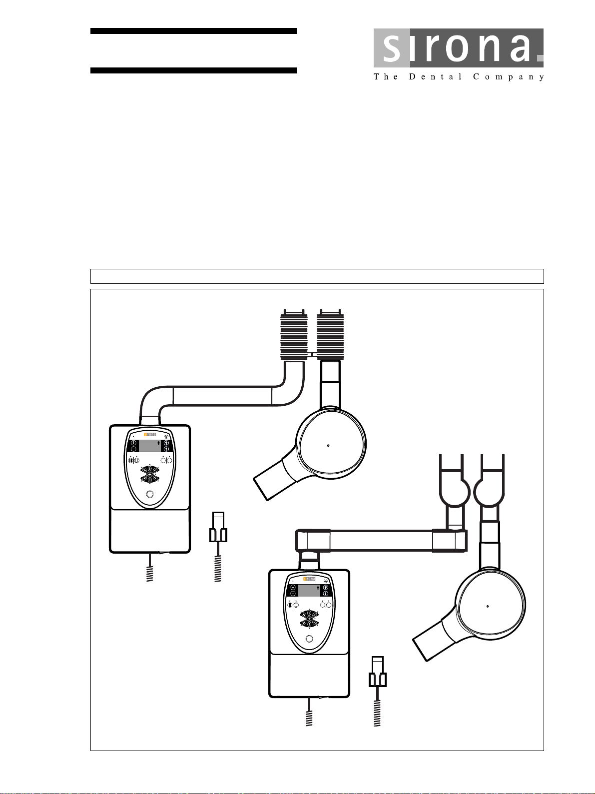
HELIODENT
PLUS
7mA DC7mA DC
70kV 60kV
S
00
8
.
HELIODENTHELIODENT
PLUS
7mA DC
70kV 60kV
S
00
8
.
MTKOMNS
ebiflabkq
fелн~дд~нбзе=oЙимбкЙгЙенл
mirp
Cover page
bеЦдблЬ
bеЦдблЬ
=
Page 2

Page 3

Sirona Dental Systems GmbH Table of contents
Installation Requirements HELIODENT
PLUS
Table of contents
1
2
3
4
Structure of the document ....................................................................................... 4
1.1 Identification of the danger levels................................................................. 4
1.2 Formats and symbols used .......................................................................... 4
Safety instructions ................................................................................................... 5
2.1 Shielding of room ......................................................................................... 5
2.2 Electromagnetic compatibility....................................................................... 5
2.3 Modifications and extensions of the system................................................. 5
Prior to installation................................................................................................... 6
3.1 Installation options........................................................................................ 6
3.2 On-site installation........................................................................................ 9
Dimensions, technical data...................................................................................... 12
4.1 Dimensions with round support arm............................................................. 12
4.1.1 Dimensions of front view with all options......................................... 12
4.1.2 Dimensions for 950 mm (37 3/8") support arm................................ 13
4.1.3 Dimensions for 700 mm (27 1/2") support arm................................ 16
4.1.4 Dimensions for 410 mm (16 1/8") support arm................................ 19
4.1.5 Dimensions mobile stand ................................................................ 22
bеЦдблЬ
4.2 Dimensions with angular support arm .......................................................... 24
4.2.1 Dimensions of front view with all options......................................... 24
4.2.2 Dimensions for 910 mm (35 7/8") support arm................................ 25
4.2.3 Dimensions for 660 mm (26") support arm...................................... 28
4.2.4 Dimensions for 370 mm (14 1/2") support arm................................ 31
4.2.5 Dimensions mobile stand ................................................................ 34
4.3 Technical data .............................................................................................. 36
5
Electromagnetic compatibility.................................................................................. 37
5.1 Accessories .................................................................................................. 37
5.2 Electromagnetic emission ............................................................................ 37
5.3 Immunity to interference............................................................................... 38
5.4 Working clearances...................................................................................... 41
62 15 037 D3507
D3507.021.01.06.02 07.2016
3
Page 4
1Structure of the document Sirona Dental Systems GmbH
1.1Identification of the danger levels Installation Requirements HELIODENT
Structure of the document
1
PLUS
1.1
Identification of the danger levels
To prevent personal injury and material damage, please observe the
warning and safety information provided in these operating instructions.
Such information is highlighted as follows:
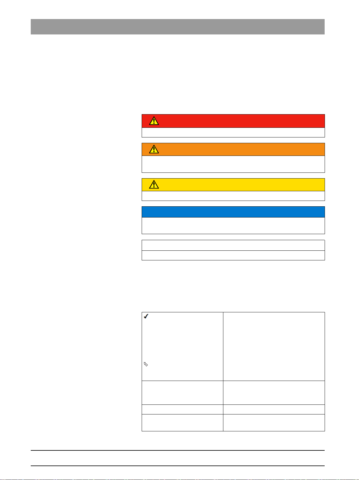
DANGER
An imminent danger that could result in serious bodily injury or death.
WARNING
A possibly dangerous situation that could result in serious bodily injury
or death.
CAUTION
A possibly dangerous situation that could result in slight bodily injury.
NOTICE
A possibly harmful situation which could lead to damage of the product
or an object in its environment.
IMPORTANT
Application instructions and other important information.
1.2
Tip: Information on making work easier.
Formats and symbols used
The formats and symbols used in this document have the following
meaning:
Prerequisite
1. First action step
2. Second action step
or
➢ Alternative action
Result
➢ Individual action step
See "Formats and symbols
used [ → 4]"
● List Designates a list.
"Command / menu item" Indicates commands, menu items or
Prompts you to do something.
Identifies a reference to another text
passage and specifies its page
number.
quotations.
4 D3507.021.01.06.02 07.2016
62 15 037 D3507
Page 5

Sirona Dental Systems GmbH 2Safety instructions
Installation Requirements HELIODENT
PLUS
Safety instructions
2
2.1Shielding of room
2.1
2.2
2.3
Shielding of room
HELIODENT Plus
When using the HELIODENT Plus X-ray tube assembly, proper shielding
of the room and operator position is essential.
It is the installer's responsibility to ensure that all local radiation
regulations and safety measures are met.
Electromagnetic compatibility
The unit should not be operated in the immediate vicinity of other devices.
If this proves to be unavoidable, the unit should be monitored to ensure
that it is operating properly.
Modifications and extensions of the system
Modifications and extensions to the unit
Modifications to this unit which might affect the safety of the system
owner, patients or other persons are prohibited by law.
For reasons of product safety, this product may be operated only with
original Sirona accessories or third-party accessories expressly approved
by Sirona. The user assumes the risk of using non-approved accessories.
bеЦдблЬ
62 15 037 D3507
D3507.021.01.06.02 07.2016
5
Page 6
3Prior to installation Sirona Dental Systems GmbH
1
S3
2
L9
S3
S9
3
L6
S3
S4
3.1Installation options Installation Requirements HELIODENT
Prior to installation
3
PLUS
3.1
Installation options
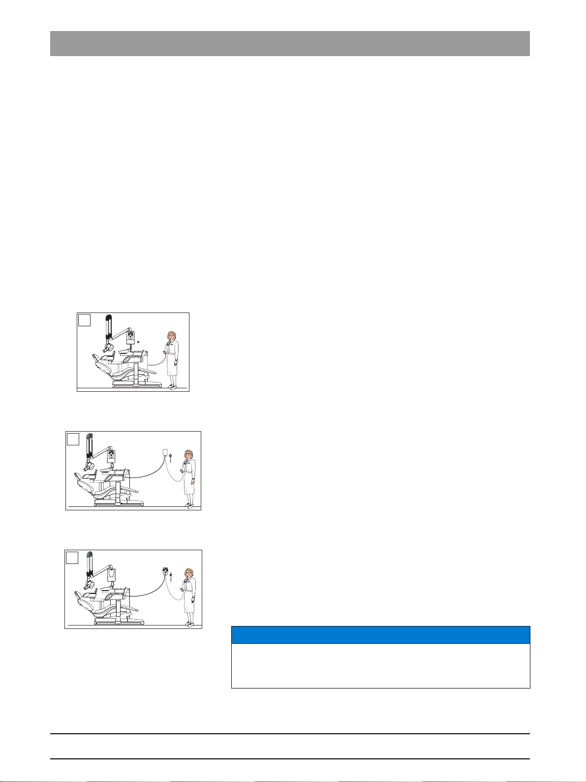
Designations for release buttons and door contact
Designations of releas e buttons and door contact
● Manual release S3
– Coiled cable
● Release key on the control membrane S4
– Directly connected to control board DX4
● Remote control release key S9
– Integrated in remote control housing
● Door contact (safety circuit) S7
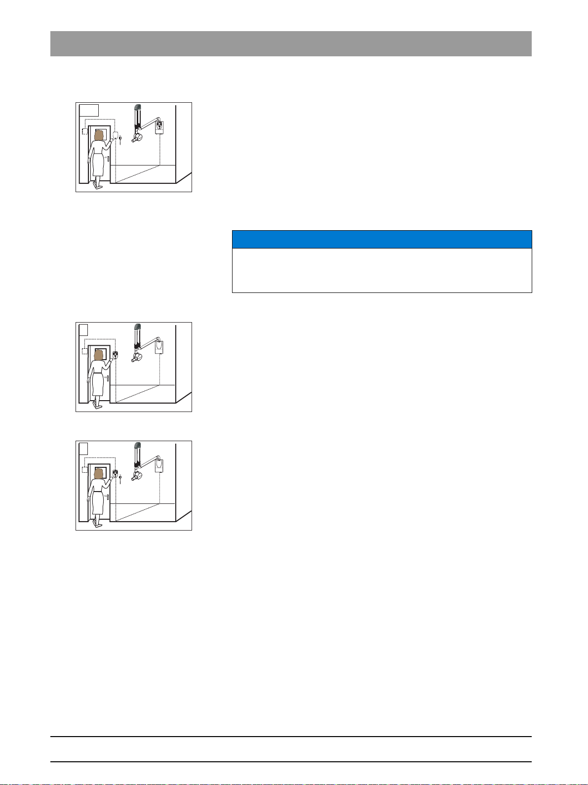
Installation option 1
Installation option 1
Release in the treatment room without remote control
● Release
– Manual release S3
Installation option 2
Installation option 2
Release in the treatment room with remote control
● Release
– Manual release S3
or
– Remote control release key S9
Installation option 3
Installation option 3
Release in the treatment room withRemote Timer
● Release
– Manual release S3
or
– Release key on the control membrane S4
NOTICE
Length of cable supplied for Remote Timer approx. 10 meters (393")
(must not be extended).
Conduit int. dia. at least 12 mm (1/2").
62 15 037 D3507
6 D3507.021.01.06.02 07.2016
Page 7
Sirona Dental Systems GmbH 3Prior to installation
4
L9
S3
S9
5
L6
S3
S4
6
L9
S7
S3
S9
Installation Requirements HELIODENT
PLUS
3.1Installation options
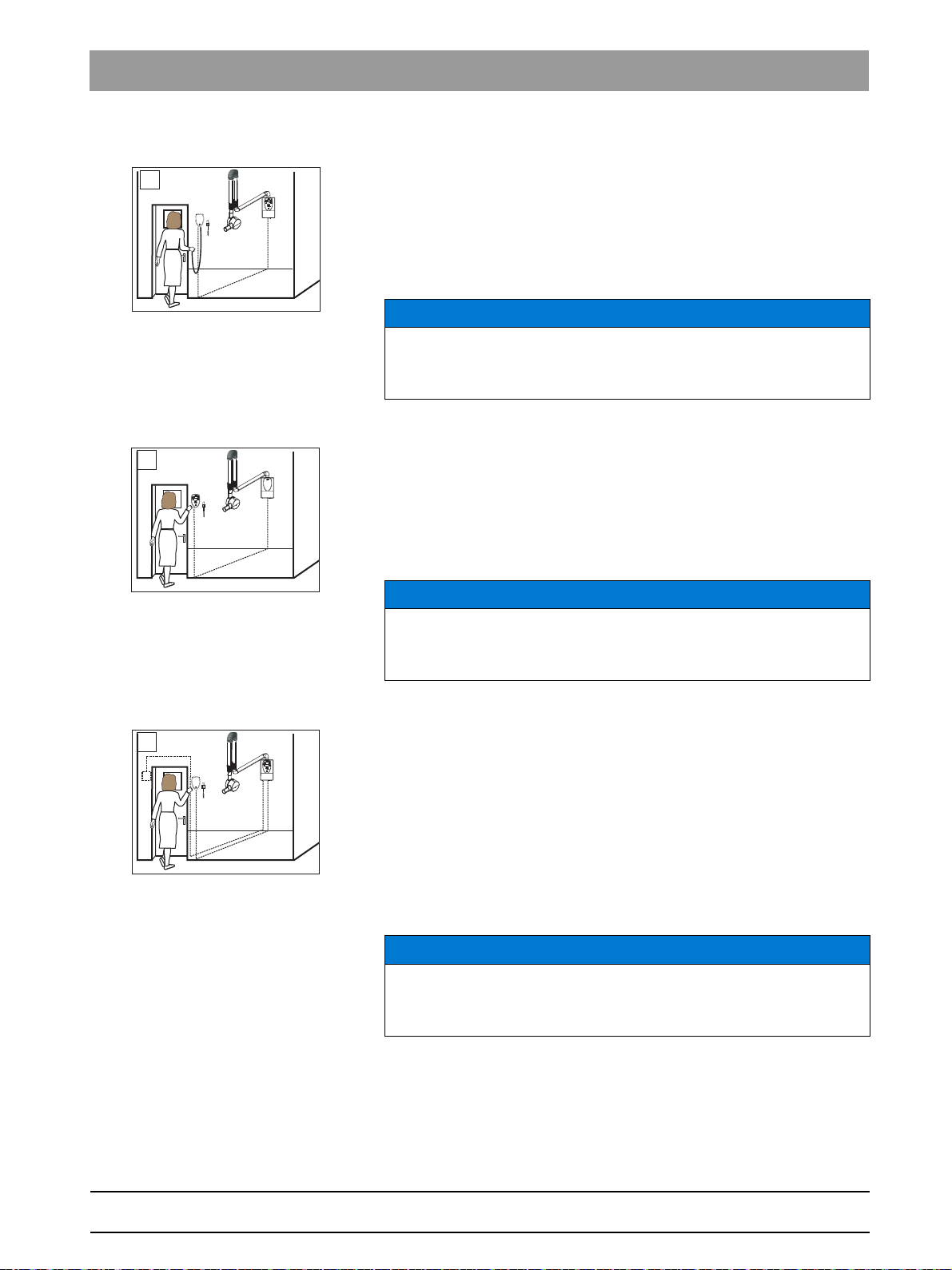
Installation option 4
Installation option 4
Release outside of the X-ray room with remote control
● Release
– Manual release S3
or
– Remote control release key S9
NOTICE
Installation prerequisites
Use of the remote control is permissible only if the yellow X-Ray LED is
visible to the operating personnel during radiation release.
Installation option 5
Installation option 5
Release outside of the X-ray room withRemote Timer
● Release
– Manual release S3
or
– Release key on the control membrane S4
bеЦдблЬ
NOTICE
Length of cable supplied for Remote Timer approx. 10 meters (393")
(must not be extended).
Conduit int. dia. at least 12 mm (1/2").
Installation option 6
Installation option 6
Release outside of the X-ray room with remote control, door contact
safety circuit
● Door contact
– Door contact S7 wired to the wall adapter
● Release
– Manual release S3
or
– Remote control release key S9
NOTICE
Installation requirement
Use of the remote control is permissible only if the yellow X-Ray LED is
visible to the operating personnel during radiation release.
62 15 037 D3507
D3507.021.01.06.02 07.2016
7
Page 8
3Prior to installation Sirona Dental Systems GmbH
6.1
L9
S7
S3
S9
7
L6
S7
S4
8
L6
S7
S3
3.1Installation options Installation Requirements HELIODENT
PLUS
Installation option 6.1
Installation option 6.1
Release outside of the X-ray room with remote control, door contact
safety circuit
● Door contact
– Door contact S7 wired to the remote control housing
● Release
– Manual release S3
or
– Remote control release key S9
NOTICE
Installation requirement
Use of the remote control is permissible only if the yellow X-Ray LED is
visible to the operating personnel during radiation release.
Installation option 7
Installation option 7
Release outside of the X-ray room with Remote Timer, door contact
safety circuit
● Door contact
– Door contact S7
● Release
– Release key on the control membrane S4
Installation option 8
Installation option 8
Release outside of the X-ray room with Remote Timer, door contact
safety circuit
● Door contact
– Door contact S7 wired to Remote Timer
● Release
– Manual release S3
8 D3507.021.01.06.02 07.2016
62 15 037 D3507
Page 9
Sirona Dental Systems GmbH 3Prior to installation
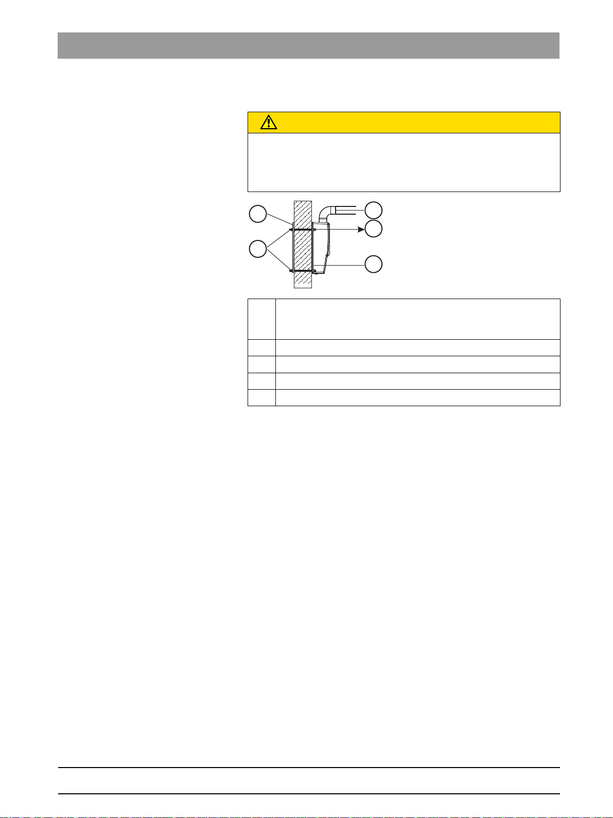
K
L
M
N
O
Installation Requirements HELIODENT
PLUS
3.2On-site installation
3.2
On-site installation
Wall properties
CAUTION
Observe wall properties
In installation situations, the technician is responsible for the
assessment of wall properties and selecting the method of attaching the
unit to the wall.
K Tensile force per screw
3600 N (800 lbf) if L ≤ 700mm (27 1/2“)
4200N(950 lbf) if L ≤ 950mm (37 3/8“)
L Length of support arm
M Mounting plate (supplied)
N Anchor plate
O Threaded bolt M8
bеЦдблЬ
● The permissible tensile force of the selected attachment must at least
equal the tensile force listed above.
● Matching wood screws for wooden beams are included in delivery.
● For all other wall structures, special wall anchors must be purchased
from a selected dealer. The wall anchors and screws should be
identical for every attachment point.
● Alternatively, an anchor plate can be used as a counter bearing. In
this case, M8 threaded rods of the appropriate length for the wall
(thickness of the wall + 2 x mounting plate thickness + attachment
material) are required.
62 15 037 D3507
D3507.021.01.06.02 07.2016
9
Page 10
3Prior to installation Sirona Dental Systems GmbH
3.2On-site installation Installation Requirements HELIODENT
PLUS
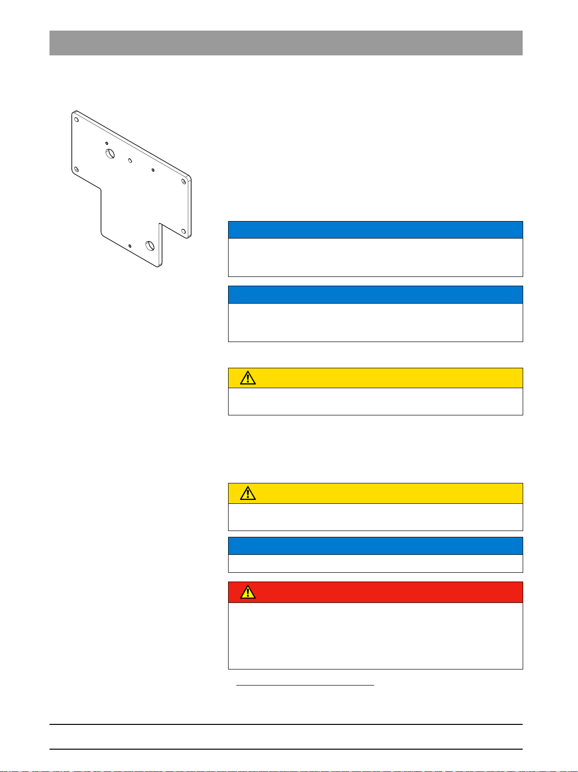
Re-use installation sites of old units
It is possible to conceal the installation site of an old unit when installing
PLUS
a HELIODENT
.
● For the replacement of vertically mounted old units (e.g. HELIODENT
DS, HELIODENT MD, Planmeca Intra
1
) an adapter plate is available
for this purpose, REF 62 42 254.
● The drill holes of some vertically mounted units (e.g. Progeny Previa
1
, Gendex 765DC 1) coincide with the dimensions of the drill holes of
PLUS
the Heliodent
. No adapter plate is required.
NOTICE
Regardless of their prior use, the existing drill holes and wall plugs must
comply with the installation regulations and must be checked by the
person performing installation.
NOTICE
The different connection areas of the old units make it necessary to
relocate the existing electrical connections (e.g. concealed installation)
on-site.
CAUTION
The on-site electrical installation must be performed according to the
valid regulations for medical electrical equipment (DIN VDE 0100-710).
● Cable for remote control or Remote Timer: Conduit ⌀ int. min. 12mm
(1/2"), requires an excess length of at least 0.25 m (10") at both ends.
● Power cable 3x1.5 mm
2
(AWG 16); required excess length for
concealed installation: 0.25m (10").
CAUTION
Do not install the cables for Remote Timer and power cables in the same
conduit.
Fixed connection
NOTICE
The Heliodent
Plus
wall model is suitable for fixed installation only.
DANGER
Perilous shock hazard!
Fixed connection!
Installing a mains plug instead of the specified fixed connection infringes
international medical regulatory actions and is prohibited. In case of
error, this puts patients, users, and other parties seriously at risk.
1. The product names mentioned may be copyrighted by their respective owners.
10 D3507.021.01.06.02 07.2016
62 15 037 D3507
Page 11
Sirona Dental Systems GmbH 3Prior to installation
Installation Requirements HELIODENT
PLUS
3.2On-site installation
Pretransformer
CAUTION
Observe the permissible nominal voltage range!
The unit can be connected to 120 V (1-phase connection) or to
200 - 240 V (1- or 2-phase connection),
for all other voltages a pre-transformer is required. As a ceiling model or
device model,
PLUS
the HELIODENT
only be connected to 200 - 240 V (1 or 2-phase connection).
For the USA only
For the USA only
Power supply:
A separate three wire grounded circuit connected directly to the central
distribution panel with an over-current protection rated for 20 amperes
should be used.
must
bеЦдблЬ
62 15 037 D3507
D3507.021.01.06.02 07.2016
11
Page 12
4Dimensions, technical data Sirona Dental Systems GmbH
2300
90 1/2”
1110
43 3/4”
281
11”
35
1 3/8”
343
13 1/2”
50
2”
75
3”
2310
91”
A
B
C
D
E
220
8 5/8”
374
14 3/4”
350
13 3/4”
F
236
9 1/4”
153
6”
1545
61”
230
9”
150
5 7/8”
40
1 1/2”
145
5 3/4”
G
H
I
J
294
11 1/2”
213
8 3/8”
176
7”
4.1Dimensions with round support arm Installation Requirements HELIODENT
Dimensions, technical data
4
PLUS
4.1
Dimensions with round support arm
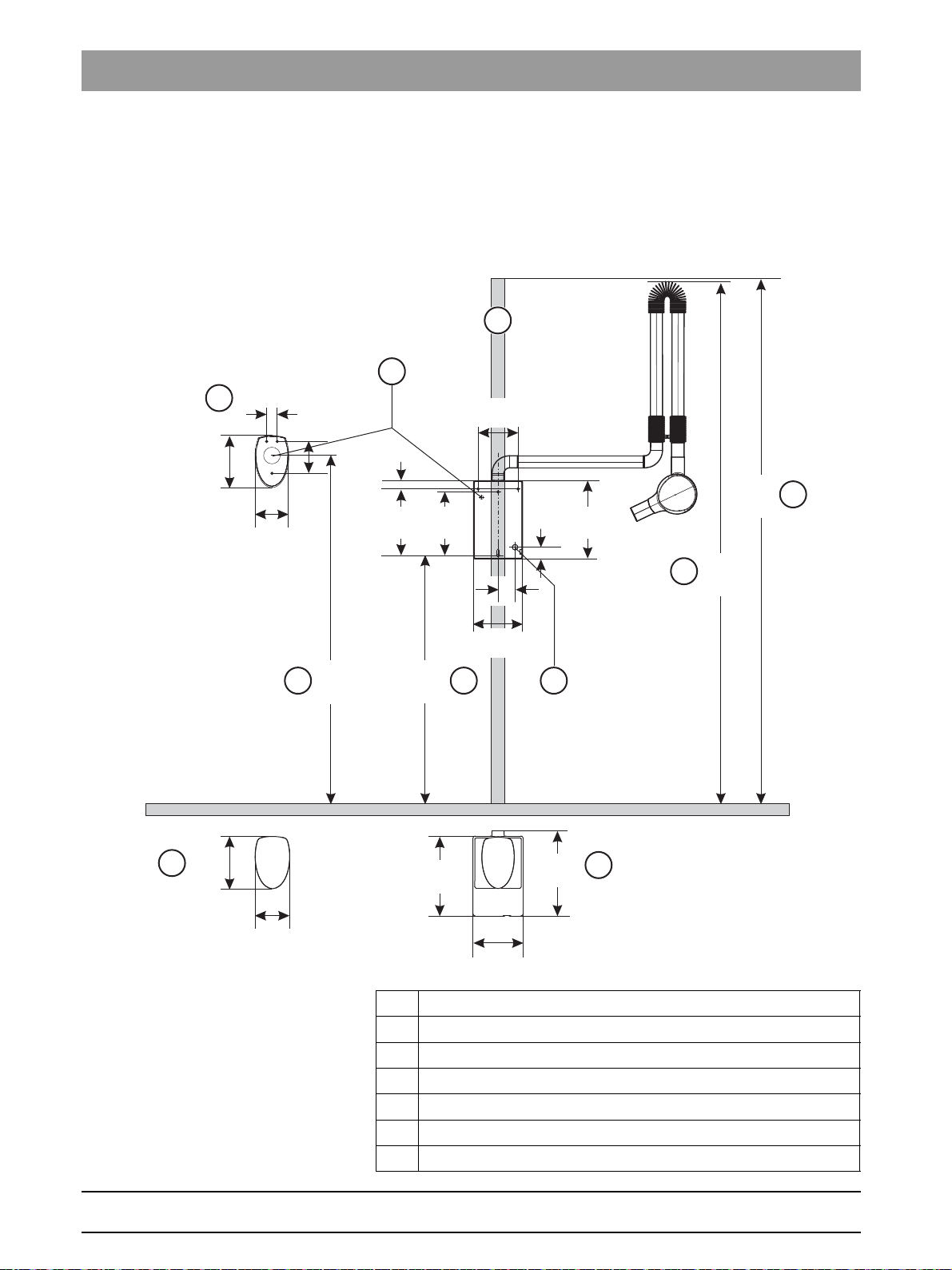
4.1.1 Dimensions of front view with all options
12 D3507.021.01.06.02 07.2016
A Recommended installation height for the wall module
B Cable bushing for network cable
C Unit height
D Ceiling height
E Wooden beam
F Wall module cover
G Cable bushing for remote control or Remote Timer
62 15 037 D3507
Page 13
Sirona Dental Systems GmbH 4Dimensions, technical data
A
max. 1840
72 1/2”
min. 930
36 5/8”
1480
58 1/4”
300°
2040
80 1/4”
1385
54 1/2”
297
11 5/8”
950
37 3/8”
T
Installation Requirements HELIODENT
PLUS
4.1Dimensions with round support arm
H Recommended installation height of remote control or Remote
Timer
I Remote control or Remote Timer
J Cover for remote control or Remote Timer
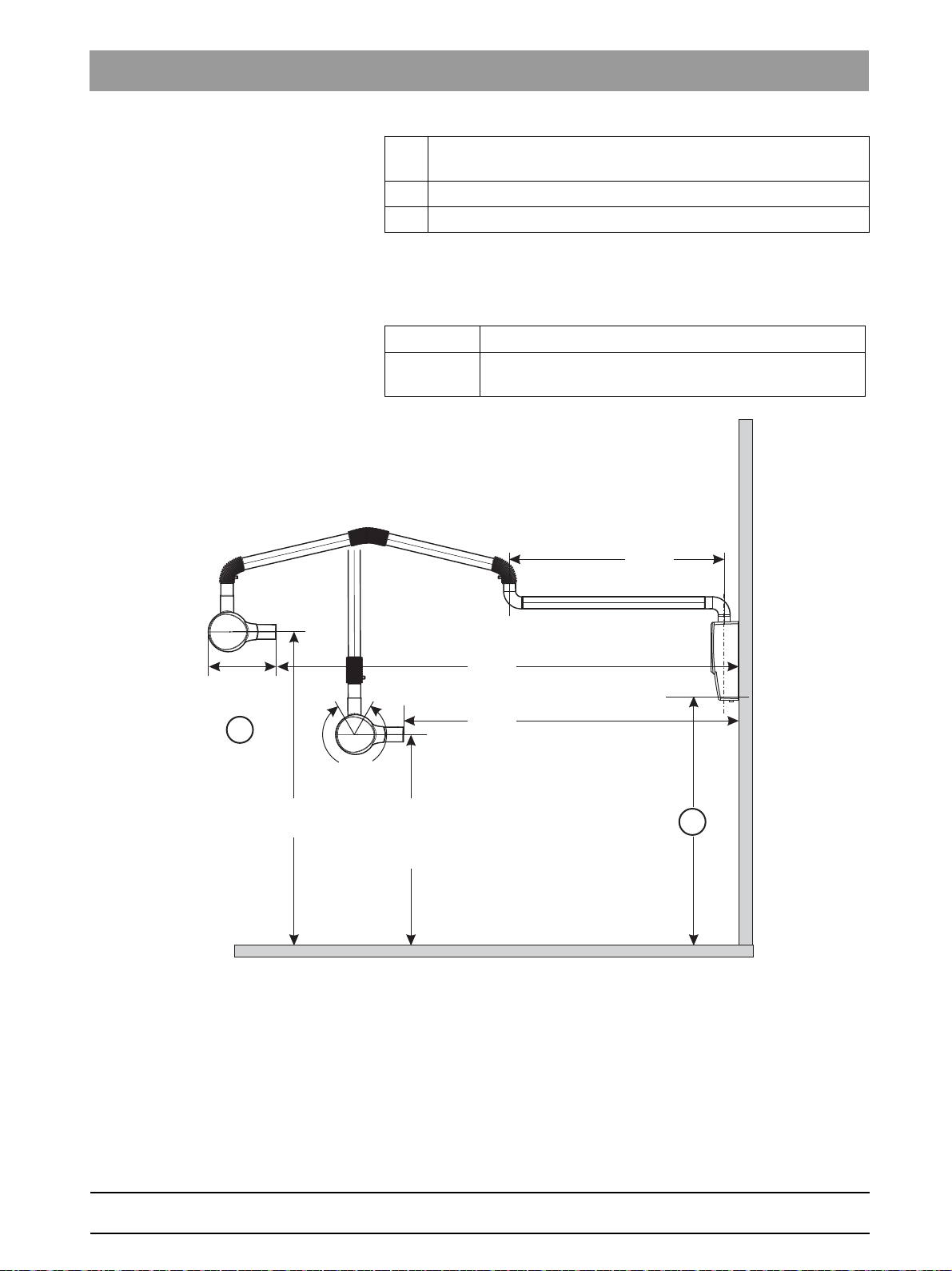
4.1.2 Dimensions for 950 mm (37 3/8") support arm
Side view
A Recommended installation height: 1110 mm (43 3/4")
T X-ray tube assembly with standard tube, 200 mm (8")
SSD
bеЦдблЬ
62 15 037 D3507
D3507.021.01.06.02 07.2016
13
Page 14
4Dimensions, technical data Sirona Dental Systems GmbH
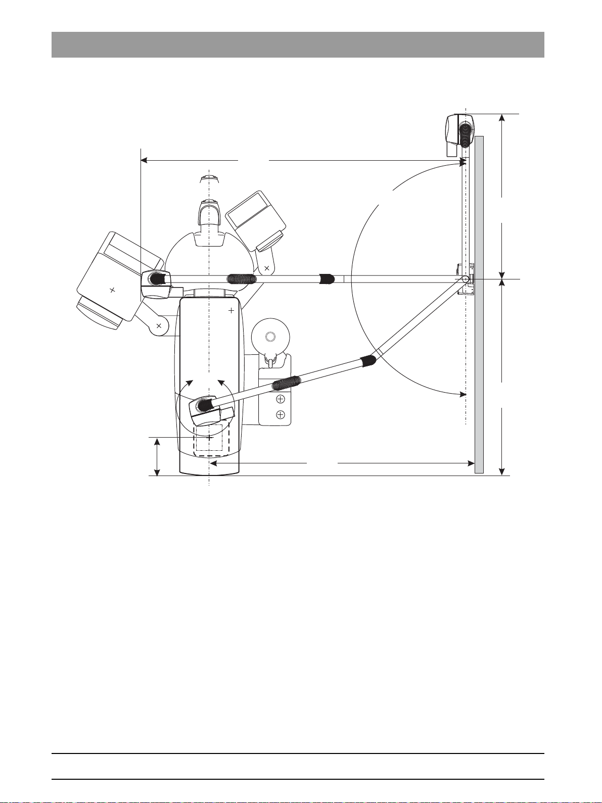
1352
54”
1150
45 1/4”
180°
1850
72 7/8”
268
10 1/2”
2280
89 3/4”
540°
4.1Dimensions with round support arm Installation Requirements HELIODENT
PLUS
Top view
14 D3507.021.01.06.02 07.2016
62 15 037 D3507
Page 15

Sirona Dental Systems GmbH 4Dimensions, technical data
min. 1300
51 1/8”
min. 1150
45 1/4”
min. 2350
92 1/2”
600
23 5/8”
220
8 5/8”
min. 1300
51 1/8”
min. 1500
59”
250
9 7/8”
220
8 5/8”
800
31 1/2”
Installation Requirements HELIODENT
PLUS
4.1Dimensions with round support arm
Minimum dimensions for X-ray rooms
with 950 mm (37 3/8") support arm
bеЦдблЬ
62 15 037 D3507
D3507.021.01.06.02 07.2016
15
Page 16

4Dimensions, technical data Sirona Dental Systems GmbH
A
max. 1840
72 1/2”
min. 930
36 5/8”
1230
48 1/2”
300°
1790
70 1/2”
1385
54 1/2”
297
11 5/8”
700
27 1/2”
T
4.1Dimensions with round support arm Installation Requirements HELIODENT
PLUS
4.1.3 Dimensions for 700 mm (27 1/2") support arm
Side view
A Recommended installation height: 1110 mm (43 3/4")
T X-ray tube assembly with standard tube, 200 mm (8")
SSD
16 D3507.021.01.06.02 07.2016
62 15 037 D3507
Page 17

Sirona Dental Systems GmbH 4Dimensions, technical data
1352
54”
1600
63”
268
10 1/2”
900
35 1/2”
2030
80”
180°
540°
Installation Requirements HELIODENT
PLUS
4.1Dimensions with round support arm
Top view
bеЦдблЬ
62 15 037 D3507
D3507.021.01.06.02 07.2016
17
Page 18

4Dimensions, technical data Sirona Dental Systems GmbH
min. 1100
43 1/4”
min. 1150
45 1/4”
min. 2080
81 7/8”
600
23 5/8”
220
8 5/8”
min. 1200
47 1/4”
min. 1200
47 1/4”
250
9 7/8”
220
8 5/8”
800
31 1/2”
4.1Dimensions with round support arm Installation Requirements HELIODENT
PLUS
Minimum dimensions for X-ray rooms
with 700 mm (27 1/2") support arm
62 15 037 D3507
18 D3507.021.01.06.02 07.2016
Page 19

Sirona Dental Systems GmbH 4Dimensions, technical data
A
max. 1840
72 1/2”
min. 930
36 5/8”
940
37”
300°
1500
59”
1385
54 1/2”
297
11 5/8”
410
16 1/8”
T
Installation Requirements HELIODENT
PLUS
4.1Dimensions with round support arm
4.1.4 Dimensions for 410 mm (16 1/8") support arm
Side view
A Recommended installation height: 1110 mm (43 3/4")
T X-ray tube assembly with standard tube, 200 mm (8")
SSD
bеЦдблЬ
62 15 037 D3507
D3507.021.01.06.02 07.2016
19
Page 20

4Dimensions, technical data Sirona Dental Systems GmbH
1352
54”
1300
51 1/8”
268
10 1/2”
610
24”
1740
68 1/2”
180°
540°
4.1Dimensions with round support arm Installation Requirements HELIODENT
PLUS
Top view
20 D3507.021.01.06.02 07.2016
62 15 037 D3507
Page 21

Sirona Dental Systems GmbH 4Dimensions, technical data
min. 1100
43 1/4”
700
27 1/2”
min. 1600
63”
620
24 3/8”
220
8 5/8”
300
11 3/4”
min. 1400
55 1/8”
min. 1200
47 1/4”
250
9 7/8”
220
8 5/8”
1000
39 3/8”
Installation Requirements HELIODENT
PLUS
4.1Dimensions with round support arm
Minimum dimensions for X-ray rooms
with 410 mm (16 1/8") support arm
bеЦдблЬ
62 15 037 D3507
D3507.021.01.06.02 07.2016
21
Page 22

4Dimensions, technical data Sirona Dental Systems GmbH
1229
48 3/8”
685
27”
350
13 3/4”
2110
83”
400
15 3/4”
4.1Dimensions with round support arm Installation Requirements HELIODENT
PLUS
4.1.5 Dimensions mobile stand
Front view
22 D3507.021.01.06.02 07.2016
62 15 037 D3507
Page 23

Sirona Dental Systems GmbH 4Dimensions, technical data
610
24”
540°
550
21 5/8”
973
38 3/8”
782
30 3/4”
1740
68 1/2”
1330
52 3/8”
1001
39 3/8”
180°
Installation Requirements HELIODENT
PLUS
4.1Dimensions with round support arm
Top view
bеЦдблЬ
62 15 037 D3507
D3507.021.01.06.02 07.2016
23
Page 24

4Dimensions, technical data Sirona Dental Systems GmbH
2325
91 1/2”
1110
43 3/4”
281
11”
35
1 3/8”
343
13 1/2”
50
2”
75
3”
2335
92”
A
B
C
D
E
220
8 5/8”
374
14 3/4”
350
13 3/4”
F
236
9 1/4”
153
6”
1545
61”
230
9”
150
5 7/8”
40
1 1/2”
145
5 3/4”
G
H
I
J
294
11 1/2”
213
8 3/8”
176
7”
4.2Dimensions with angular support arm Installation Requirements HELIODENT
PLUS
4.2
Dimensions with angular support arm
4.2.1 Dimensions of front view with all options
A Recommended installation height for the wall module
B Cable bushing for network cable
C Unit height
D Ceiling height
E Wooden beam
F Wall module cover
G Cable bushing for remote control or Remote Timer
H Recommended installation height of remote control or Remote
Timer
24 D3507.021.01.06.02 07.2016
62 15 037 D3507
Page 25

Sirona Dental Systems GmbH 4Dimensions, technical data
A
max. 1840
72 1/2”
min. 930
36 5/8”
1450
57”
300°
2050
80 3/4”
1400
55 1/8”
297
11 5/8”
T
1300
51 3/16”
910
35 7/8”
Installation Requirements HELIODENT
PLUS
4.2Dimensions with angular support arm
I Remote control or Remote Timer
J Cover for remote control or Remote Timer
4.2.2 Dimensions for 910 mm (35 7/8") support arm
Side view
A Recommended installation height: 1110 mm (43 3/4")
T X-ray tube assembly with standard tube, 200 mm (8")
SSD
bеЦдблЬ
62 15 037 D3507
D3507.021.01.06.02 07.2016
25
Page 26

4Dimensions, technical data Sirona Dental Systems GmbH
1352
54”
1150
45 1/4”
180°
1850
72 7/8”
268
10 1/2”
2280
89 3/4”
540°
4.2Dimensions with angular support arm Installation Requirements HELIODENT
PLUS
Top view
26 D3507.021.01.06.02 07.2016
62 15 037 D3507
Page 27

Sirona Dental Systems GmbH 4Dimensions, technical data
min. 1300
51 1/8”
min. 1150
45 1/4”
min. 2350
92 1/2”
600
23 5/8”
220
8 5/8”
min. 1300
51 1/8”
min. 1500
59”
250
9 7/8”
220
8 5/8”
800
31 1/2”
Installation Requirements HELIODENT
PLUS
4.2Dimensions with angular support arm
Minimum dimensions for X-ray rooms
with 910 mm (35 7/8") support arm
bеЦдблЬ
62 15 037 D3507
D3507.021.01.06.02 07.2016
27
Page 28

4Dimensions, technical data Sirona Dental Systems GmbH
A
max. 1840
72 1/2”
min. 930
36 5/8”
1200
47 1/4”
300°
1800
70 7/8”
1400
55 1/8”
297
11 5/8”
T
1300
51 3/16”
660
26”
4.2Dimensions with angular support arm Installation Requirements HELIODENT
PLUS
4.2.3 Dimensions for 660 mm (26") support arm
Side view
A Recommended installation height: 1110 mm (43 3/4")
T X-ray tube assembly with standard tube, 200 mm (8")
SSD
28 D3507.021.01.06.02 07.2016
62 15 037 D3507
Page 29

Sirona Dental Systems GmbH 4Dimensions, technical data
1352
54”
1600
63”
268
10 1/2”
900
35 1/2”
2030
80”
180°
540°
Installation Requirements HELIODENT
PLUS
4.2Dimensions with angular support arm
Top view
bеЦдблЬ
62 15 037 D3507
D3507.021.01.06.02 07.2016
29
Page 30

4Dimensions, technical data Sirona Dental Systems GmbH
min. 1100
43 1/4”
min. 1150
45 1/4”
min. 2080
81 7/8”
600
23 5/8”
220
8 5/8”
min. 1200
47 1/4”
min. 1200
47 1/4”
250
9 7/8”
220
8 5/8”
800
31 1/2”
4.2Dimensions with angular support arm Installation Requirements HELIODENT
PLUS
Minimum dimensions for X-ray rooms
with 660 mm (26") support arm
62 15 037 D3507
30 D3507.021.01.06.02 07.2016
Page 31

Sirona Dental Systems GmbH 4Dimensions, technical data
A
max. 1840
72 1/2”
min. 930
36 5/8”
370
14 1/2”
910
35 7/8”
300°
1510
59 1/5”
1400
55 1/8”
297
11 5/8”
T
1300
51 3/16”
Installation Requirements HELIODENT
PLUS
4.2Dimensions with angular support arm
4.2.4 Dimensions for 370 mm (14 1/2") support arm
Side view
A Recommended installation height: 1110 mm (43 3/4")
T X-ray tube assembly with standard tube, 200 mm (8")
SSD
bеЦдблЬ
62 15 037 D3507
D3507.021.01.06.02 07.2016
31
Page 32

4Dimensions, technical data Sirona Dental Systems GmbH
1352
54”
1300
51 1/8”
268
10 1/2”
610
24”
1740
68 1/2”
180°
540°
4.2Dimensions with angular support arm Installation Requirements HELIODENT
PLUS
Top view
32 D3507.021.01.06.02 07.2016
62 15 037 D3507
Page 33

Sirona Dental Systems GmbH 4Dimensions, technical data
min. 1100
43 1/4”
700
27 1/2”
min. 1600
63”
620
24 3/8”
220
8 5/8”
300
11 3/4”
min. 1400
55 1/8”
min. 1200
47 1/4”
250
9 7/8”
220
8 5/8”
1000
39 3/8”
Installation Requirements HELIODENT
PLUS
4.2Dimensions with angular support arm
Minimum dimensions for X-ray rooms
with 370 mm (14 1/2") support arm
bеЦдблЬ
62 15 037 D3507
D3507.021.01.06.02 07.2016
33
Page 34

4Dimensions, technical data Sirona Dental Systems GmbH
1229
48 3/8”
685
27”
350
13 3/4”
2125
83 6/8”
400
15 3/4”
4.2Dimensions with angular support arm Installation Requirements HELIODENT
PLUS
4.2.5 Dimensions mobile stand
Front view
34 D3507.021.01.06.02 07.2016
62 15 037 D3507
Page 35

Sirona Dental Systems GmbH 4Dimensions, technical data
540°
610
24”
550
21 5/8”
973
38 3/8”
1740
68 1/2”
1370
54”
1001
39 3/8”
180°
782
30 3/4”
Installation Requirements HELIODENT
PLUS
4.2Dimensions with angular support arm
Top view
bеЦдблЬ
62 15 037 D3507
D3507.021.01.06.02 07.2016
35
Page 36

4Dimensions, technical data Sirona Dental Systems GmbH
4.3Technical data Installation Requirements HELIODENT
PLUS
4.3
Technical data
Dimensions of the packaging
HELIODENT
Round support arm system
Angular support arm system
Mobile stand
Weight incl. / without packaging
HELIODENT
Round support arm system
Angular support arm system
Mobile stand
Power supply connection
Line voltage
wall model
ceiling model, unit model
Line voltage variation ± 10%
Internal line resistance At 120 V: 0.3 Ω
Nominal current At 120 V: 10 A
Fuse 16 A slow blow
Power consumption ≤ 1.2 kW
PLUS
PLUS
87 cm x 91 cm x 29 cm
34 1/4" x 35 7/8" x 11 1/2"
99 cm x 94 cm x 29 cm
39" x 37" x 11 1/2"
120 cm x 80 cm x 40 cm
47 1/4" x 31 1/2" x 15 3/4"
31 kg / 24 kg
68.34 lb / 53 lb
37 kg / 30 kg
81.57 lb / 66.14
128 kg / 105 kg
282.2 lb / 231.5 lb
120 V, 200 V - 240 V, 50 / 60 Hz
200 V - 240 V, 50 / 60 Hz
for 200 V - 240 V: 0.8 Ω
for 200 V - 240 V: 6 A - 5 A
Transport and operating conditio ns
Transport and operating conditions:
Transport and storage
-40°C – +70°C (-40°F – 158°F)
temperature:
Air humidity: 10% – 95%
Operating conditions as
specified in IEC 60601-1:
Ambient temperature +10 °C – +40 °C
(50 °F – 104 °F)
Relative humidity: 30% – 75%
Recommended operating
temperature:
18°C - 35°C (64°F - 95°F)
With room temperatures > 35°C (> 95°F)
Sirona recommends the use of an air
conditioning system.
Operating altitude: ≤ 3000 m
36 D3507.021.01.06.02 07.2016
62 15 037 D3507
Page 37

Sirona Dental Systems GmbH 5Electromagnetic compatibility
Installation Requirements HELIODENT
PLUS
Electromagnetic compatibility
5
Heliodent Plus
5.1Accessories
NOTICE
HELIODENT
compatibility (EMC) according to IEC 60601-1-2.
HELIODENT
the following information is necessary to ensure safe operation
regarding EMC aspects.
Plus
complies with the requirements for electromagnetic
Plus
is referred to in the following as "UNIT". Observance of
5.1
5.2
Accessories
Designation of the interface cables Order no.
2
LIYCY 2x0.25mm
remote release, 10m
LIYYC 8x0.22mm
Remote Timer, 10m
3x1.5mm
● The UNIT may be operated only with accessories and spare parts
● The UNIT should not be operated immediately adjacent to other
2
NYM
approved by Sirona. Unapproved accessories and spare parts may
lead to an increased emission or to a reduced immunity to
interference.
devices. If this proves to be unavoidable, the UNIT should be
monitored to ensure that it is operating properly.
(AWG 24) remote cable L9 for
2
(AWG 24) remote cable L6 for
62 42 064
62 42 056
Commercially
available
Electromagnetic emission
The UNIT is intended for operation in the electromagnetic environment
specified below.
bеЦдблЬ
The customer or user of the UNIT should make sure that it is used in such
an environment.
Emission measurement Conformity Electromagnetic environment - guidelines
RF emissions according to CISPR 11 Group 1 The UNIT uses RF energy only for its internal
function. Therefore, its RF emissions are very low
and are not likely to cause any interference in
nearby electronic equipment.
RF emissions according to CISPR 11 Class B The UNIT is intended for use in all facilities,
Harmonics
according to IEC 61000-3-2
Voltage fluctuations / flicker according
to IEC 61000-3-3
62 15 037 D3507
D3507.021.01.06.02 07.2016
Class A
coincides
including residential areas and in any facilities
connected directly to a public power supply
providing electricity to buildings used for residential
purposes.
37
Page 38

5Electromagnetic compatibility Sirona Dental Systems GmbH
5.3Immunity to interference Installation Requirements HELIODENT
PLUS
Interference immunity
tests
Electrostatic discharge
(ESD) according to
IEC 61000-4-2
Electrical fast transient/
burst according to
IEC 61000-4-4
Surge voltages according
to
IEC 61000-4-5
Voltage dips, short
interruptions and
variations of the power
supply according to
IEC 61000-4-11
Magnetic field of power
frequencies (50/60 Hz)
according to
IEC 61000-4-8
Note: U
is the AC supply voltage prior to application of the test level.
T
5.3
Immunity to interference
The UNIT is intended for operation in the electromagnetic environment
specified below.
The customer or user of the UNIT should make sure that it is used in such
an environment.
IEC 60601-1-2 test
level
± 8 kV contact
discharge
± 15 kV air discharge
Compliance level Electromagnetic environment -
guidelines
± 8 kV contact
discharge
± 15 kV air discharge
Floors should be made of wood or
concrete or finished with ceramic
tiling. If the floor is covered with
synthetic material, the relative
humidity should be at least 30%.
± 1kV for input and
output lines
± 2 kV for power supply
lines
± 1 kV differential mode
voltage
± 2 kV common mode
voltage
Voltage dips:
0% U
with 1/2 period at 0°, 45°, 90°, 135°, 180°,
T
225°, 270° and 315°
0% U
with 1 period and
T
70% U
with 25 periods at 50 Hz and
T
30 periods at 60 Hz each at 0°
Short interruptions:
0% U
with 250 periods at 50 Hz and
T
± 1 kV for input and
output lines
± 2 kV for power supply
lines
± 1 kV differential mode
voltage
± 2 kV common mode
voltage
The quality of the line power supply
should be that of a typical commercial
or hospital environment.
The quality of the line power supply
should be that of a typical commercial
or hospital environment.
The quality of the line power supply
should be that of a typical commercial
or hospital environment.
If the user of the UNIT requires it to
continue functioning following
interruptions of the power supply, it is
recommended to have the UNIT
powered by an uninterruptible power
supply or a battery.
300 periods at 60 Hz
30 A/m 30 A/m Power frequency magnetic fields
should be at levels characteristic of a
typical location in a typical commercial
or hospital environment.
Portable and mobile radio equipment
must not be used within the
recommended working clearance from
the UNIT and its cables, which is
calculated based on the equation
suitable for the relevant transmission
frequency.
Recommended working clearance:
38 D3507.021.01.06.02 07.2016
62 15 037 D3507
Page 39

Sirona Dental Systems GmbH 5Electromagnetic compatibility
Installation Requirements HELIODENT
PLUS
5.3Immunity to interference
Interference immunity
tests
Conducted RF
interference
IEC 61000-4-6
Radiated RF interference
IEC 61000-4-3
IEC 60601-1-2 test
level
3 V
eff
150 kHz to 80 MHz
3 V/m
80 MHz to 800 MHz
3 V/m
800 MHz to 2.7 GHz
Compliance level Electromagnetic environment -
guidelines
3 V
3 V
3 V
eff
eff
eff
1
1
1
d= [1.2] √P
d= [1.2] √P
at 80 MHz to 800 MHz
d= [2.3] √P
at 800 MHz to 2.7 GHz
with P as the power rating of the
transmitter in watts (W) according to
the transmitter manufacturer's
specifications and d as recommended
safety distance in meters (m).
Field strengths from fixed RF
transmitters, as determined by an
electromagnetic site survey
be less than the compliance level
each frequency range.
Interference is possible in the vicinity
of equipment bearing the following
2
should
3
in
bеЦдблЬ
graphic symbol.
1. The higher frequency range applies at 80 MHz and 800 MHz.
2. The field strengths of fixed transmitters, such as base stations of
radiotelephones and mobile agricultural radio broadcast services,
amateur radio stations, AM and FM radio broadcast and TV
broadcast cannot be predicted theoretically with accuracy. A site
survey is recommended to assess the electromagnetic environment
due to fixed RF transmitters. If the measured field strength in the
location in which the UNIT is used exceeds the applicable RF
compliance level above, the UNIT should be observed to verify
normal operation. If unusual performance characteristics are
observed, it may be necessary to take additional measures such as
reorientation or repositioning of the UNIT.
3. Over the frequency range 150 kHz to 80 MHz, field strengths should
be less than 3 V/m.
62 15 037 D3507
D3507.021.01.06.02 07.2016
39
Page 40

5Electromagnetic compatibility Sirona Dental Systems GmbH
5.3Immunity to interference Installation Requirements HELIODENT
PLUS
Test frequency
(MHz)
385 380 - 390 TETRA 400 Pulse modulation
Frequency
(a)
band
(MHz)
Radio service
(a)
Modulation (b) Power max.
(W)
1.8 0.3 27
Distance (m) Immunity test
level
(V/m)
(b)
18 Hz
450 430 – 470 GMRS 460,
FRS 460
FM(c)
± 5 kHz stroke
20.328
1 kHz sinus
710
745
780
810
870
930
704 - 787 LTE band 13, 17Pulse modulation
(b)
217 Hz
800 - 960 GSM 800/900,
TETRA 800,
iDEN 820,
Pulse modulation
(b)
18 Hz
0.2 0.3 9
20.328
CDMA 850,
LTE band 5
1720
1845
1970
1700 - 1990 GSM 1800;
CDMA 1900;
GSM 1900;
Pulse modulation
(b)
217 Hz
20.328
DECT;
LTE band 1, 3,
4, 25; UMTS
2450 2400 - 2570 Bluetooth,
WLAN,
802,11 b/g/n,
Pulse modulation
(b)
217 Hz
20.328
RFID 2450,
LTE band 7
5240
5500
5785
5100 - 5800 WLAN 802.11
a/n
Pulse modulation
(b)
217 Hz
0.2 0.3 9
Note:
If necessary, the distance between the transmitting antenna and the ME unit or ME system can be reduced to 1 m
in order to achieve the immunity test level. The 1 m test distance conforms to IEC 61000-4-3.
(a) For some radio services, only the frequencies for the radio link between the mobile communication device and
the base station (uplink) have been recorded in the table.
(b) The carrier must be modulated with a square-wave signal with 50% duty cycle.
(c) Alternatively to the frequency modulation (FM), a pulse modulation with 50% duty cycle at 18 Hz can be used, as
this, if not the actual modulation, would represent the worst case.
40 D3507.021.01.06.02 07.2016
62 15 037 D3507
Page 41

Sirona Dental Systems GmbH 5Electromagnetic compatibility
Installation Requirements HELIODENT
PLUS
5.4Working clearances
5.4
Recommended working clearances
between portable and mobile HF
communication devices and the UNIT
Power rating of the transmitter
[W]
0.01 0.12 0.12 0.23
0.1 0.38 0.38 0.73
11.21.22.3
10 3.8 3.8 7.3
100 12 12 23
Working clearance according to transmission frequency [m]
150 kHz - 80 MHz 80 MHz - 800 MHz 800 MHz - 2.5 GHz
d= [1,2] √P d= [1,2] √P d= [2,3] √P
Working clearances
The UNIT is intended for operation in an electromagnetic environment,
where radiated RF interference is checked. The customer or the user of
the UNIT can help prevent electromagnetic interference by maintaining a
minimum distance between portable and mobile RF communications
equipment (transmitters) and the UNIT - depending on the maximum
output power of the communication device, as shown below.
The recommended safety distance d in meters (m) can be determined for
transmitters, whose maximum power rating is not specified in the above
table, using the equation that belongs to the corresponding column,
wherein P is the maximum power rating of the transmitter in watts (W)
according to the transmitter manufacturer.
bеЦдблЬ
Note 1
The higher frequency range applies at 80 MHz and 800 MHz.
Note 2
These guidelines may not apply in all cases. The propagation of
electromagnetic waves is influenced by their absorption and reflection by
buildings, objects and persons.
62 15 037 D3507
D3507.021.01.06.02 07.2016
41
Page 42

5Electromagnetic compatibility Sirona Dental Systems GmbH
5.4Working clearances Installation Requirements HELIODENT
PLUS
42 D3507.021.01.06.02 07.2016
62 15 037 D3507
Page 43

Page 44

tЙ=кЙлЙкоЙ=нЬЙ=кбЦЬн=нз=г~вЙ=~еу=~днЙк~нбзел=пЬбЕЬ=г~у=ДЙ=кЙимбкЙЗ=ЗмЙ=нз=нЙЕЬебЕ~д=бгйкзоЙгЙенлK
«=pбкзе~=aЙен~д=pулнЙгл=dгДe=OMNS pйк~ЕЬЙW ЙеЦдблЕЬ mкбенЙЗ=бе=dЙкг~еу
aPRMTKMONKMNKMSKMO MTKOMNS ûKJkêKW= NOO=PVN
pбкзе~=aЙен~д=pулнЙгл=dгДe `çåí~Åí=áå=íÜÉ=rp^W
pбкзе~=aЙен~дI=fеЕK
c~Дкбвлнк~≈Й=PN
aJSQSOR=_ЙелЬЙбг
dЙкг~еу
пппKлбкзе~KЕзг
QUPR=páêçå~=aêáîÉ
`Ь~кдзннЙI=k`=OUOTP
rp^
lêÇÉê=kç
SO=NR=MPT=aPRMT
 Loading...