

Page 1

SINUMERIK
SINUMERIK 840D sl
SINUMERIK 840D sl STEP 7 Toolbox
V17
Valid for
Control system
SINUMERIK 840D sl/840DE sl
Software
CNC software for 840D sl/840DE sl V4.5, V4.7, V4.8,
V4.91, V4.92, V4.93, V4.94, V4.95
Introduction
Fundamental safety
instructions
1
2
Conguration Manual
Product information
Conguring the NCU
Programming the PLC
Conguring networks
Conguring telegrams and
drive units
Conguring I/O
Tag selection with NC VAR
selector
3
4
5
6
7
8
9
07/2021
6FC5397-0GP40-0BA2
Importing user alarms
Safety conguration
10
11
Page 2
Legal information
Warning notice system
This manual contains notices you have to observe in order to ensure your personal safety, as well as to prevent damage
to property. The notices referring to your personal safety are highlighted in the manual by a safety alert symbol, notices
referring only to property damage have no safety alert symbol. These notices shown below are graded according to
the degree of danger.
DANGER
indicates that death or severe personal injury will result if proper precautions are not taken.
WARNING
indicates that death or severe personal injury may result if proper precautions are not taken.
CAUTION
indicates that minor personal injury can result if proper precautions are not taken.
NOTICE
indicates that property damage can result if proper precautions are not taken.
If more than one degree of danger is present, the warning notice representing the highest degree of danger will be
used. A notice warning of injury to persons with a safety alert symbol may also include a warning relating to property
damage.
Qualied Personnel
The product/system described in this documentation may be operated only by personnel qualied for the specic
task in accordance with the relevant documentation, in particular its warning notices and safety instructions.
Qualied personnel are those who, based on their training and experience, are capable of identifying risks and
avoiding potential hazards when working with these products/systems.
Proper use of Siemens products
Note the following:
WARNING
Siemens products may only be used for the applications described in the catalog and in the relevant technical
documentation. If products and components from other manufacturers are used, these must be recommended or
approved by Siemens. Proper transport, storage, installation, assembly, commissioning, operation and maintenance
are required to ensure that the products operate safely and without any problems. The permissible ambient
conditions must be complied with. The information in the relevant documentation must be observed.
Trademarks
All names identied by ® are registered trademarks of Siemens AG. The remaining trademarks in this publication may
be trademarks whose use by third parties for their own purposes could violate the rights of the owner.
Disclaimer of Liability
We have reviewed the contents of this publication to ensure consistency with the hardware and software described.
Since variance cannot be precluded entirely, we cannot guarantee full consistency. However, the information in this
publication is reviewed regularly and any necessary corrections are included in subsequent editions.
Siemens AG
Digital Industries
Postfach 48 48
90026 NÜRNBERG
GERMANY
Document order number: 6FC5397-0GP40-0BA2
Ⓟ 06/2021 Subject to change
Copyright © Siemens AG 2013 - 2021.
All rights reserved
Page 3

Table of contents
1 Introduction........................................................................................................................................... 7
1.1 About SINUMERIK ................................................................................................................ 7
1.2 About this documentation ................................................................................................... 7
1.2.1
1.3 Documentation on the internet............................................................................................ 8
1.3.1 Documentation overview SINUMERIK 840D sl....................................................................... 8
1.3.2 Documentation overview SINUMERIK operator components ................................................. 9
1.4 Feedback on the technical documentation ........................................................................... 9
1.5 mySupport documentation .................................................................................................. 9
1.6 Service and Support........................................................................................................... 10
1.7 Important product information .......................................................................................... 12
2 Fundamental safety instructions......................................................................................................... 13
2.1 General safety instructions................................................................................................. 13
2.2 Equipment damage due to electric elds or electrostatic discharge ..................................... 17
2.3 Warranty and liability for application examples ................................................................... 17
Structure, content, target group
... ...................................................................................... 7
2.4 Security information .......................................................................................................... 17
2.5 Residual risks of power drive systems ................................................................................. 19
3 Product information............................................................................................................................. 21
3.1 Validity of the description................................................................................................... 21
3.2 Product features ................................................................................................................ 21
3.3 Installation notes ............................................................................................................... 22
3.4 Limitations for use ............................................................................................................. 23
4 Conguring the NCU............................................................................................................................ 25
4.1 SINUMERIK NCU................................................................................................................. 25
4.1.1 Structure of SINUMERIK NCU.............................................................................................. 25
4.1.2 Insert NCU ......................................................................................................................... 26
4.2 Insert NX module............................................................................................................... 27
4.3 Replacing a device or upgrading rmware .......................................................................... 32
4.3.1 Replacing the NCU ............................................................................................................. 32
4.3.2 Replacing an NX................................................................................................................. 32
4.3.3 Basic procedure ................................................................................................................. 33
4.4 Establish the communication connection ........................................................................... 36
4.5 Load hardware conguration into the PLC........................................................................... 37
4.6 Creating SINUMERIK PLC archives ....................................................................................... 40
SINUMERIK 840D sl STEP 7 Toolbox V17
Conguration Manual, 07/2021, 6FC5397-0GP40-0BA2 3
Page 4

Table of contents
4.6.1 Creating a SINUMERIK PLC archive ...................................................................................... 40
4.6.2 Available SINUMERIK archive types..................................................................................... 43
4.6.3 External tools for SINUMERIK archives ................................................................................ 44
4.6.4 Creating a PLC hardware upgrade archive........................................................................... 44
4.6.5 Creating a PLC commissioning archive................................................................................ 46
4.6.6 Creating a PLC reload archive ............................................................................................. 48
5 Programming the PLC .......................................................................................................................... 51
5.1 General information about the PLC program....................................................................... 51
5.1.1 Introduction....................................................................................................................... 51
5.1.2 Execution structure............................................................................................................ 51
5.1.3 Using copy templates......................................................................................................... 54
5.1.4 Block listing as table........................................................................................................... 57
5.1.5 Blocks with user-specic adaptations.................................................................................. 61
5.1.6 Assignment overview......................................................................................................... 62
5.1.7 Generating blocks at runtime on the NCU........................................................................... 63
5.2 Opening the PLC basic program system library.................................................................... 64
5.3 Adding the PLC basic program............................................................................................ 65
5.4 Conicts when copying blocks ........................................................................................... 70
5.5 Correcting OB1 .................................................................................................................. 71
5.6 Upgrading the PLC basic program....................................................................................... 71
5.7 Copying blocks from one project into another..................................................................... 73
5.8 Use and handling of groups ............................................................................................... 76
5.9 Create blocks from external sources ................................................................................... 77
5.10 Exporting PLC symbols for SINUMERIK Operate................................................................... 78
5.10.1 Creating and loading PLC symbols...................................................................................... 78
5.10.2 Exporting PLC symbols ....................................................................................................... 80
5.10.3 Importing PLC symbols....................................................................................................... 82
5.11 Edit blocks ......................................................................................................................... 83
6 Conguring networks .......................................................................................................................... 85
6.1 Conguring an Ethernet Interface....................................................................................... 85
6.2 Conguring PROFIBUS DP ................................................................................................... 86
6.3 Conguring Integrated PROFIBUS (DP Integrated) ............................................................... 87
6.4 Conguring PROFINET........................................................................................................ 88
6.5 Conguring PROFINET IO with IRT....................................................................................... 89
6.5.1 Overview........................................................................................................................... 89
6.5.2 Rules and requirements...................................................................................................... 89
6.5.3 Isochronous-capable modules identication ....................................................................... 91
6.5.4 Conguring isochronous NC-controlled drives..................................................................... 93
6.5.5 Conguring I/O used by NC isochronously........................................................................... 94
6.5.6 Conguring the NCU .......................................................................................................... 95
6.5.7 Conguring PROFINET IO IRT devices .................................................................................. 96
6.5.8 Conguring IO modules or drive telegrams......................................................................... 98
6.5.9 Conguring the input delay for digital input modules........................................................ 101
SINUMERIK 840D sl STEP 7 Toolbox V17
4 Conguration Manual, 07/2021, 6FC5397-0GP40-0BA2
Page 5

Table of contents
6.5.10 Conguring sync domains ................................................................................................ 102
6.5.11 Match values between PROFINET IO and PROFIBUS Integrated .......................................... 103
6.5.12 Assigning drive addresses to the NCU machine data.......................................................... 104
6.5.13 Assigning I/O addresses to the NCU machine data............................................................. 105
7 Conguring telegrams and drive units.............................................................................................. 107
7.1 Overview......................................................................................................................... 107
7.2 Standard telegram conguration...................................................................................... 108
7.3 Viewing I/O addresses in the TIA Portal ............................................................................. 108
7.4 Changing the addressing schematic ................................................................................. 109
7.5 Resetting telegrams ......................................................................................................... 111
7.6 Displaying or adapting the telegram conguration............................................................ 112
7.6.1 Overview......................................................................................................................... 112
7.6.2 Calling the telegram conguration ................................................................................... 113
7.6.3 Structure of the "Telegram conguration" dialog ............................................................... 113
7.6.4 Changing the properties of send telegrams (actual value)................................................. 114
7.6.5 Changing the properties of receive telegrams (setpoint)................................................... 117
7.6.6 Adapting the number of drives......................................................................................... 119
7.7 Available telegram types.................................................................................................. 120
7.7.1 Telegrams for the transfer of standard data (PROFIdrive)................................................... 120
7.7.2 Telegrams in SINUMERIK Safety Integrated (SPL) mode ..................................................... 122
7.7.3 Telegrams for PROFIsafe communication.......................................................................... 122
7.7.4 Telegrams for SIC/SCC communication.............................................................................. 123
7.8 Adapting I/O start addresses............................................................................................. 124
7.8.1 Introduction..................................................................................................................... 124
7.8.2 PROFIdrive telegrams for standard data............................................................................ 125
7.8.3 PROFIdrive telegrams for Safety Integrated (SPL)............................................................... 128
7.8.4 PROFIsafe/PROFIdrive telegrams for Safety Integrated plus (F-PLC) .................................... 130
7.9 Deviations from the standard I/O addressing schematic..................................................... 133
7.9.1 Overview......................................................................................................................... 133
7.9.2 Matching of deviating I/O addresses................................................................................. 134
7.9.2.1 Matching I/O addresses for use of the optimized I/O addressing schematic ........................ 134
7.9.2.2 Matching user-specic adaptations................................................................................... 135
7.9.3 Viewing messages in the info area.................................................................................... 135
7.9.4 Availability of suitable I/O addresses ................................................................................ 136
8 Conguring I/O................................................................................................................................... 139
8.1 Inserting ADI4 module (840 sl)......................................................................................... 139
8.2 Installing general station description les for SINUMERIK I/O............................................. 142
8.3 Inserting the SINUMERIK I/O module PP72/48 ................................................................... 144
8.4 Inserting SINUMERIK MCP/MPP......................................................................................... 146
9 Tag selection with NC VAR selector ................................................................................................... 149
9.1 NC VAR selector ............................................................................................................... 149
9.2 Selecting tags and saving as STL le ................................................................................. 149
9.3 Adding a tag le (STL) in the TIA Portal ............................................................................. 151
SINUMERIK 840D sl STEP 7 Toolbox V17
Conguration Manual, 07/2021, 6FC5397-0GP40-0BA2 5
Page 6

Table of contents
10 Importing user alarms ....................................................................................................................... 153
10.1 Overview......................................................................................................................... 153
10.2 Exporting TS les from SINUMERIK Operate ...................................................................... 153
10.3 Language assignment in language-dependent texts ......................................................... 154
10.4 Enable project languages ................................................................................................. 156
10.5 Importing SINUMERIK PLC alarm texts .............................................................................. 156
11 Safety conguration .......................................................................................................................... 159
11.1 Introduction..................................................................................................................... 159
11.2 Representation of safety-related resources in the TIA Portal .............................................. 159
11.3 Changing the Safety Integrated mode .............................................................................. 162
11.4 Parameterization of relevant properties ............................................................................ 163
11.5 Availability of I/O addresses at the mode change............................................................... 167
11.6 Licensing ......................................................................................................................... 169
11.6.1 Overview......................................................................................................................... 169
11.6.2 Software options for Safety Integrated (SPL)..................................................................... 170
11.6.3 Software options for Safety Integrated plus (F-PLC)........................................................... 171
11.7 Conguring Safety Integrated (SPL).................................................................................. 172
11.7.1 Introduction..................................................................................................................... 172
11.7.2 Conguring the F-peripherals ........................................................................................... 172
11.7.3 Parameterizing F-input modules....................................................................................... 174
11.7.4 Conguring drives with F-functions .................................................................................. 175
11.7.5 Parameterizing F-output modules..................................................................................... 177
11.7.6 Conguration of the PROFIsafe addresses (peripherals)..................................................... 177
11.7.7 Conguration of the PROFIsafe addresses (drives)............................................................. 181
11.7.8 Parameterizing PROFIsafe telegrams................................................................................. 183
11.8 Conguring Safety Integrated plus (F-PLC) ........................................................................ 184
11.8.1 Introduction..................................................................................................................... 184
11.8.2 Conguring Safety Integrated plus (F-PLC) ........................................................................ 186
11.8.3 Creating a second F-runtime group for Safety Integrated plus (F-PLC)................................ 188
11.8.4 Conguring PROFIsafe...................................................................................................... 190
11.8.5 Checking the PROFIsafe address ....................................................................................... 191
Index .................................................................................................................................................. 195
SINUMERIK 840D sl STEP 7 Toolbox V17
6 Conguration Manual, 07/2021, 6FC5397-0GP40-0BA2
Page 7

Introduction
1.1 About SINUMERIK
rom simple, standardized CNC machines to premium modular machine designs – the
F
SINUMERIK CNCs oer the right solution for all machine concepts. Whether for individual parts
or mass production, simple or complex workpieces – SINUMERIK is the highly dynamic
automation solution, integrated for all areas of production. From prototype construction and
tool design to mold making, all the way to large-scale series production.
1
Visit our website for more information SINUMERIK (
1.2 About this documentation
1.2.1
Target group
Benets
Standard scope
Structure, content, target group
This document is intended for rst-time users who want to familiarize themselves with the
product.
Conguration Manual enables the target group to apply the rules and guidelines to be
The
observed when conguring products and systems. It helps you select products and functions.
The Conguration Manual helps the target group create a system or plant conguration.
https://www.siemens.com/sinumerik).
This documentation only describes the functionality of the standard version. This may dier
from the scope of the functionality of the system that is actually supplied. Please refer to the
ordering documentation only for the functionality of the supplied drive system.
It may be possible to execute other functions in the system which are not described in this
documentation. This does not, however, represent an obligation to supply such functions with
a new control or when servicing.
For reasons of clarity, this documentation cannot include all of the detailed information on all
product types. Further, this documentation cannot take into consideration every conceivable
type of installation, operation and service/maintenance.
The machine manufacturer must document any additions or modications they make to the
product themselves.
SINUMERIK 840D sl STEP 7 Toolbox V17
Conguration Manual, 07/2021, 6FC5397-0GP40-0BA2 7
Page 8

Introduction
1.3 Documentation on the internet
Websites of third-party companies
This document may contain hyperlinks to third-party websites. Siemens is not responsible for
and shall not be liable for these websites and their content. Siemens has no control over the
information which appears on these websites and is not responsible for the content and
information provided there. The user bears the risk for their use.
1.3 Documentation on the internet
1.3.1 Documentation overview SINUMERIK 840D sl
You will nd extensive documentation on the functions of SINUMERIK 840D sl from version 4.8
SP4 at 840D sl documentation overview (https://support.industry.siemens.com/cs/ww/en/view/
109766213).
You can display documents or download them in PDF and HTML5 format.
The documentation is divided into the following categories:
• User: Operating
• User: Programming
• Manufacturer/Service: Functions
• Manufacturer/Service: Hardware
• Manufacturer/Service: Conguration/Setup
• Manufacturer/Service: Safety Integrated
• Manufacturer/Service: SINUMERIK Integrate/MindApp
• Information and training
• Manufacturer/Service: SINAMICS
SINUMERIK 840D sl STEP 7 Toolbox V17
8 Conguration Manual, 07/2021, 6FC5397-0GP40-0BA2
Page 9

1.5 mySupport documentation
1.3.2 Documentation overview SINUMERIK operator components
Comprehensive documentation about the SINUMERIK operator components is provided in the
Documentation overview SINUMERIK operator components (https://
support.industry.siemens.com/cs/document/109783841/technische-dokumentation-zusinumerik-bedienkomponenten?dti=0&lc=en-WW).
You can display documents or download them in PDF and HTML5 format.
The documentation is divided into the following categories:
• Operator Panels
• Machine control panels
• Machine Pushbutton Panel
• Handheld Unit/Mini handheld devices
• Further operator components
An overview of the most important documents, entries and links to SINUMERIK is provided at
SINUMERIK Overview - Topic Page (https://support.industry.siemens.com/cs/document/
109766201/sinumerik-an-overview-of-the-most-important-documents-and-links?
dti=0&lc=en-WW).
Introduction
1.4 Feedback on the technical documentation
If you have any questions, suggestions or corrections regarding the technical documentation
which is published in the Siemens Industry Online Support, use the link "Send feedback" link
which appears at the end of the entry.
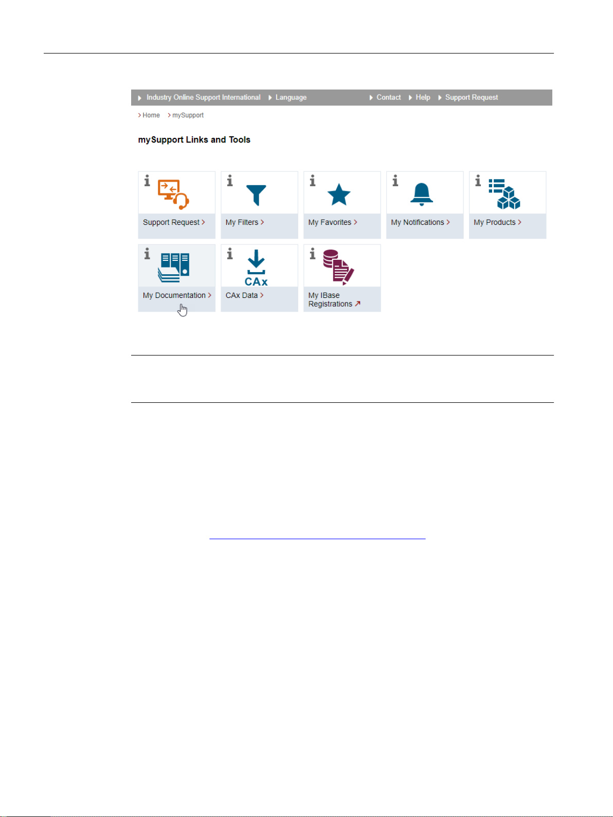
1.5 mySupport documentation
With the "mySupport documentation" web-based system you can compile your own individual
documentation based on Siemens content, and adapt it for your own machine documentation.
To start the application, click on the "My Documentation" tile on the mySupport homepage
(https://support.industry.siemens.com/cs/ww/en/my):
SINUMERIK 840D sl STEP 7 Toolbox V17
Conguration Manual, 07/2021, 6FC5397-0GP40-0BA2 9
Page 10
Introduction
1.6 Service and Support
The congured manual can be exported in RTF, PDF or XML format.
Note
Siemens content that supports the mySupport documentation application can be identied by
the presence of the "Congure" link.
1.6 Service and Support
Product support
You can nd more information about products on the internet:
Product support (https://support.industry.siemens.com/cs/ww/en/)
The following is provided at this address:
• Up-to-date product information (product announcements)
• FAQs (frequently asked questions)
• Manuals
• Downloads
• Newsletters with the latest information about your products
• Global forum for information and best practice sharing between users and specialists
• Local contact persons via our Contacts at Siemens database (→ "Contact")
• Information about eld services, repairs, spare parts, and much more (→ "Field Service")
SINUMERIK 840D sl STEP 7 Toolbox V17
10 Conguration Manual, 07/2021, 6FC5397-0GP40-0BA2
Page 11
Technical support
Country-specic telephone numbers for technical support are provided on the internet at
address (
If you have any technical questions, please use the online form in the "Support Request" area.
https://support.industry.siemens.com/cs/ww/en/sc/4868) in the "Contact" area.
Training
You can nd information on SITRAIN at the following address (https://www.siemens.com/
sitrain).
SITRAIN oers training courses for automation and drives products, systems and solutions from
Siemens.
Siemens support on the go
Introduction
1.6 Service and Support
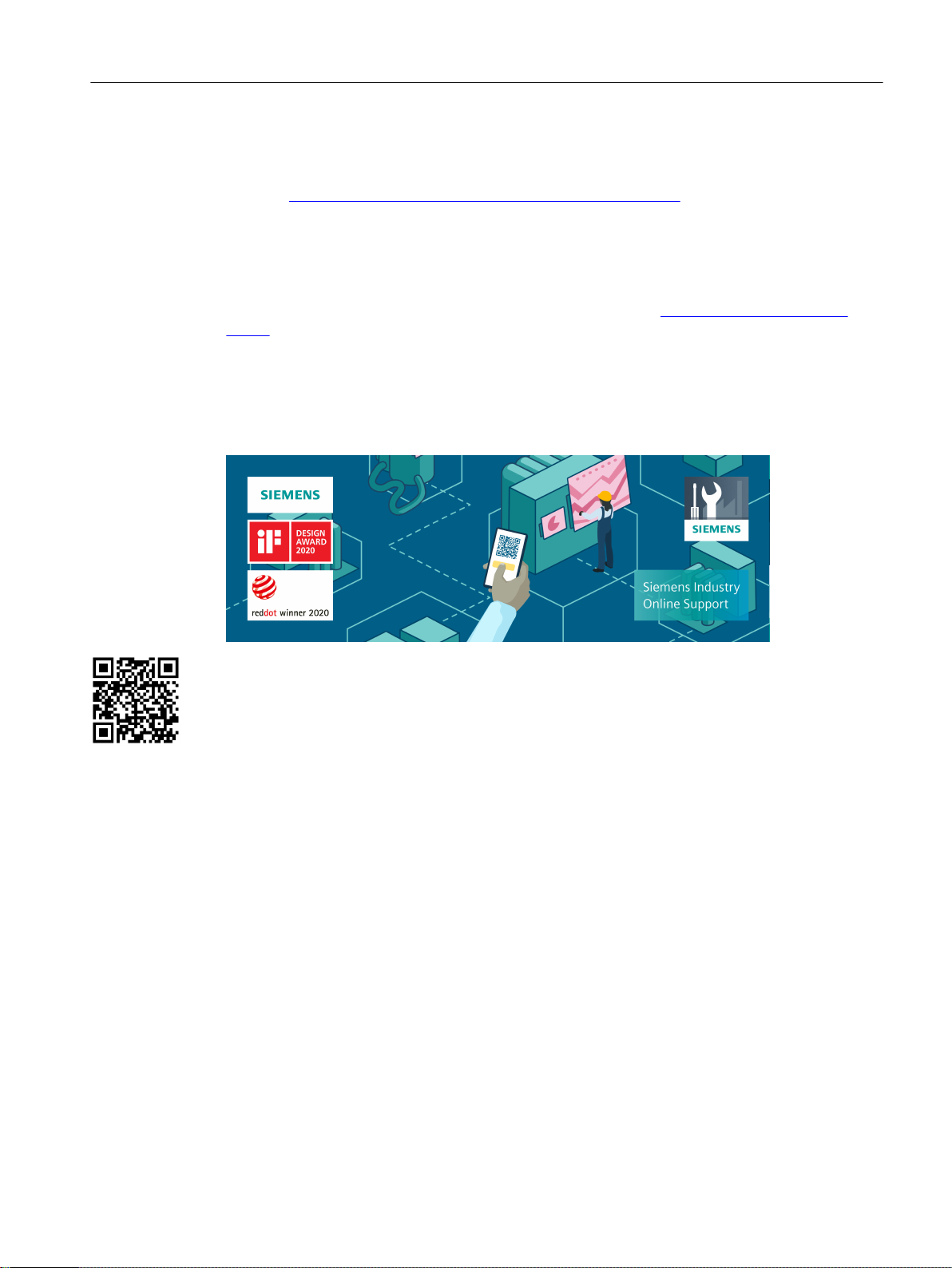
With the award-winning "Siemens Industry Online Support" app, you can access more than
300,000 documents for Siemens Industry products – any time and from anywhere. The app can
support you in areas including:
• Resolving problems when implementing a project
• Troubleshooting when faults develop
• Expanding a system or planning a new system
Furthermore, you have access to the Technical Forum and other articles from our experts:
• FAQs
• Application examples
• Manuals
• Certicates
• Product announcements and much more
The "Siemens Industry Online Support" app is available for Apple iOS and Android.
Data matrix code on the nameplate
The data matrix code on the nameplate contains the specic device data. This code can be read
with a smartphone and technical information about the device displayed via the "Industry
Online Support" mobile app.
SINUMERIK 840D sl STEP 7 Toolbox V17
Conguration Manual, 07/2021, 6FC5397-0GP40-0BA2 11
Page 12

Introduction
1.7 Important product information
1.7 Important product information
Using OpenSSL
This product can contain the following software:
• Software developed by the OpenSSL project for use in the OpenSSL toolkit
• Cryptographic software created by Eric Young.
• Software developed by Eric Young
You can nd more information on the internet:
• OpenSSL (
• Cryptsoft (https://www.cryptsoft.com)
https://www.openssl.org)
Compliance with the General Data Protection Regulation
Siemens observes standard data protection principles, in particular the data minimization rules
(privacy by design).
For this product, this means:
The product does not process or store any personal data, only technical function data (e.g. time
stamps). If the user links this data with other data (e.g. shift plans) or if he/she stores personrelated data on the same data medium (e.g. hard disk), thus personalizing this data, he/she must
ensure compliance with the applicable data protection stipulations.
SINUMERIK 840D sl STEP 7 Toolbox V17
12 Conguration Manual, 07/2021, 6FC5397-0GP40-0BA2
Page 13
Fundamental safety instructions
2.1 General safety instructions
WARNING
Electric shock and danger to life due to other energy sources
Touching live components can result in death or severe injury.
• Only work on electrical devices when you are qualied for this job.
• Always observe the country-specic safety rules.
Generally, the following steps apply when establishing safety:
1. Prepare for disconnection. Notify all those who will be aected by the procedure.
2. Isolate the drive system from the power supply and take measures to prevent it being
switched back on again.
3. Wait until the discharge time specied on the warning labels has elapsed.
4. Check that there is no voltage between any of the power connections, and between any of
the power connections and the protective conductor connection.
5. Check whether the existing auxiliary supply circuits are de-energized.
6. Ensure that the motors cannot move.
7. Identify all other dangerous energy sources, e.g. compressed air, hydraulic systems, or
water. Switch the energy sources to a safe state.
8. Check that the correct drive system is completely locked.
2
After you have completed the work, restore the operational readiness in the inverse sequence.
WARNING
Electric shock due to connection to an unsuitable power supply
When equipment is connected to an unsuitable power supply, exposed components may carry
a hazardous voltage. Contact with hazardous voltage can result in severe injury or death.
• Only use power supplies that provide SELV (Safety Extra Low Voltage) or PELV- (Protective
Extra Low Voltage) output voltages for all connections and terminals of the electronics
modules.
SINUMERIK 840D sl STEP 7 Toolbox V17
Conguration Manual, 07/2021, 6FC5397-0GP40-0BA2 13
Page 14
Fundamental safety instructions
2.1 General safety instructions
WARNING
Electric shock due to equipment damage
Improper handling may cause damage to equipment. For damaged devices, hazardous
voltages can be present at the enclosure or at exposed components; if touched, this can result
in death or severe injury.
• Ensure compliance with the limit values specied in the technical data during transport,
storage and operation.
• Do not use any damaged devices.
WARNING
Electric shock due to unconnected cable shields
Hazardous touch voltages can occur through capacitive cross-coupling due to unconnected
cable shields.
• As a minimum, connect cable shields and the cores of cables that are not used at one end
at the grounded housing potential.
WARNING
Electric shock if there is no ground connection
For missing or incorrectly implemented protective conductor connection for devices with
protection class I, high voltages can be present at open, exposed parts, which when touched,
can result in death or severe injury.
• Ground the device in compliance with the applicable regulations.
NOTICE
Damage to equipment due to unsuitable tightening tools.
Unsuitable tightening tools or fastening methods can damage the screws of the equipment.
• Be sure to only use screwdrivers which exactly match the heads of the screws.
• Tighten the screws with the torque specied in the technical documentation.
• Use a torque wrench or a mechanical precision nut runner with a dynamic torque sensor and
speed limitation system.
SINUMERIK 840D sl STEP 7 Toolbox V17
14 Conguration Manual, 07/2021, 6FC5397-0GP40-0BA2
Page 15
Fundamental safety instructions
2.1 General safety instructions
WARNING
Spread of re from built-in devices
In the event of re outbreak, the enclosures of built-in devices cannot prevent the escape of
re and smoke. This can result in serious personal injury or property damage.
• Install built-in units in a suitable metal cabinet in such a way that personnel are protected
against re and smoke, or take other appropriate measures to protect personnel.
• Ensure that smoke can only escape via controlled and monitored paths.
WARNING
Unexpected movement of machines caused by radio devices or mobile phones
Using radio devices or mobile telephones in the immediate vicinity of the components can
result in equipment malfunction. Malfunctions may impair the functional safety of machines
and can therefore put people in danger or lead to property damage.
• Therefore, if you move closer than 20 cm to the components, be sure to switch o radio
devices or mobile telephones.
• Use the "SIEMENS Industry Online Support app" only on equipment that has already been
switched o.
WARNING
Fire due to inadequate ventilation clearances
Inadequate ventilation clearances can cause overheating of components with subsequent re
and smoke. This can cause severe injury or even death. This can also result in increased
downtime and reduced service lives for devices/systems.
• Ensure compliance with the specied minimum clearance as ventilation clearance for the
respective component.
NOTICE
Overheating due to inadmissible mounting position
The device may overheat and therefore be damaged if mounted in an inadmissible position.
• Only operate the device in admissible mounting positions.
SINUMERIK 840D sl STEP 7 Toolbox V17
Conguration Manual, 07/2021, 6FC5397-0GP40-0BA2 15
Page 16
Fundamental safety instructions
2.1 General safety instructions
WARNING
Unexpected movement of machines caused by inactive safety functions
Inactive or non-adapted safety functions can trigger unexpected machine movements that
may result in serious injury or death.
• Observe the information in the appropriate product documentation before commissioning.
• Carry out a safety inspection for functions relevant to safety on the entire system, including
all safety-related components.
• Ensure that the safety functions used in your drives and automation tasks are adjusted and
activated through appropriate parameterizing.
• Perform a function test.
• Only put your plant into live operation once you have guaranteed that the functions
relevant to safety are running correctly.
Note
Important safety notices for Safety Integrated functions
If you want to use Safety Integrated functions, you must observe the safety notices in the Safety
Integrated manuals.
WARNING
Malfunctions of the machine as a result of incorrect or changed parameter settings
As a result of incorrect or changed parameterization, machines can malfunction, which in turn
can lead to injuries or death.
• Protect the parameterization against unauthorized access.
• Handle possible malfunctions by taking suitable measures, e.g. emergency stop or
emergency o.
SINUMERIK 840D sl STEP 7 Toolbox V17
16 Conguration Manual, 07/2021, 6FC5397-0GP40-0BA2
Page 17

Fundamental safety instructions
2.4 Security information
2.2 Equipment damage due to electric elds or electrostatic discharge
Electrostatic sensitive devices (ESD) are individual components, integrated circuits, modules or
devices that may be damaged by either electric elds or electrostatic discharge.
NOTICE
Equipment damage due to electric elds or electrostatic discharge
Electric elds or electrostatic discharge can cause malfunctions through damaged individual
components, integrated circuits, modules or devices.
• Only pack, store, transport and send electronic components, modules or devices in their
original packaging or in other suitable materials, e.g conductive foam rubber of aluminum
foil.
• Only touch components, modules and devices when you are grounded by one of the
following methods:
– Wearing an ESD wrist strap
– Wearing ESD shoes or ESD grounding straps in ESD areas with conductive ooring
• Only place electronic components, modules or devices on conductive surfaces (table with
ESD surface, conductive ESD foam, ESD packaging, ESD transport container).
2.3 Warranty and liability for application examples
Application examples are not binding and do not claim to be complete regarding conguration,
equipment or any eventuality which may arise. Application examples do not represent specic
customer solutions, but are only intended to provide support for typical tasks.
As the user you yourself are responsible for ensuring that the products described are operated
correctly. Application examples do not relieve you of your responsibility for safe handling when
using, installing, operating and maintaining the equipment.
2.4 Security information
Siemens provides products and solutions with industrial security functions that support the
secure operation of plants, systems, machines and networks.
In order to protect plants, systems, machines and networks against cyber threats, it is necessary
to implement – and continuously maintain – a holistic, state-of-the-art industrial security
concept. Siemens’ products and solutions constitute one element of such a concept.
Customers are responsible for preventing unauthorized access to their plants, systems,
machines and networks. Such systems, machines and components should only be connected to
an enterprise network or the internet if and to the extent such a connection is necessary and only
when appropriate security measures (e.g. rewalls and/or network segmentation) are in place.
For additional information on industrial security measures that may be implemented, please
visit
https://www.siemens.com/industrialsecurity (https://www.siemens.com/industrialsecurity).
SINUMERIK 840D sl STEP 7 Toolbox V17
Conguration Manual, 07/2021, 6FC5397-0GP40-0BA2 17
Page 18
Fundamental safety instructions
2.4 Security information
Siemens’ products and solutions undergo continuous development to make them more secure.
Siemens strongly recommends that product updates are applied as soon as they are available
and that the latest product versions are used. Use of product versions that are no longer
supported, and failure to apply the latest updates may increase customer’s exposure to cyber
threats.
To stay informed about product updates, subscribe to the Siemens Industrial Security RSS Feed
under
https://www.siemens.com/industrialsecurity (https://new.siemens.com/global/en/products/
services/cert.html#Subscriptions).
Further information is provided on the Internet:
Industrial Security Conguration Manual (https://support.industry.siemens.com/cs/ww/en/
view/108862708)
WARNING
Unsafe operating states resulting from software manipulation
Software manipulations, e.g. viruses, Trojans, or worms, can cause unsafe operating states in
your system that may lead to death, serious injury, and property damage.
• Keep the software up to date.
• Incorporate the automation and drive components into a holistic, state-of-the-art industrial
security concept for the installation or machine.
• Make sure that you include all installed products into the holistic industrial security concept.
• Protect les stored on exchangeable storage media from malicious software by with suitable
protection measures, e.g. virus scanners.
• On completion of commissioning, check all security-related settings.
SINUMERIK 840D sl STEP 7 Toolbox V17
18 Conguration Manual, 07/2021, 6FC5397-0GP40-0BA2
Page 19

2.5 Residual risks of power drive systems
When assessing the machine- or system-related risk in accordance with the respective local
regulations (e.g., EC Machinery Directive), the machine manufacturer or system installer must
take into account the following residual risks emanating from the control and drive components
of a drive system:
1. Unintentional movements of driven machine or system components during commissioning,
operation, maintenance, and repairs caused by, for example,
– Hardware and/or software errors in the sensors, control system, actuators, and cables and
connections
– Response times of the control system and of the drive
– Operation and/or environmental conditions outside the specication
– Condensation/conductive contamination
– Parameterization, programming, cabling, and installation errors
– Use of wireless devices/mobile phones in the immediate vicinity of electronic components
– External inuences/damage
Fundamental safety instructions
2.5 Residual risks of power drive systems
– X-ray, ionizing radiation and cosmic radiation
2. Unusually high temperatures, including open ames, as well as emissions of light, noise,
particles, gases, etc., can occur inside and outside the components under fault conditions
caused by, for example:
– Component failure
– Software errors
– Operation and/or environmental conditions outside the specication
– External inuences/damage
3. Hazardous shock voltages caused by, for example:
– Component failure
– Inuence during electrostatic charging
– Induction of voltages in moving motors
– Operation and/or environmental conditions outside the specication
– Condensation/conductive contamination
– External inuences/damage
4. Electrical, magnetic and electromagnetic elds generated in operation that can pose a risk to
people with a pacemaker, implants or metal replacement joints, etc., if they are too close
5. Release of environmental pollutants or emissions as a result of improper operation of the
system and/or failure to dispose of components safely and correctly
6. Inuence of network-connected communication systems, e.g. ripple-control transmitters or
data communication via the network
For more information about the residual risks of the drive system components, see the relevant
sections in the technical user documentation.
SINUMERIK 840D sl STEP 7 Toolbox V17
Conguration Manual, 07/2021, 6FC5397-0GP40-0BA2 19
Page 20

Fundamental safety instructions
2.5 Residual risks of power drive systems
SINUMERIK 840D sl STEP 7 Toolbox V17
20 Conguration Manual, 07/2021, 6FC5397-0GP40-0BA2
Page 21

Product information
3.1 Validity of the description
These notes take precedence over statements in other documents.
Please read the notes carefully since important information for installation and use of the
software is included for you.
Notes that were no longer able to be taken into account in the online help can be found under
Limitations for use (Page 23).
3.2 Product features
Functional scope
Software component SINUMERIK 840D sl STEP 7 Toolbox V17 contains the following tools and
functions:
• Supplementation of the hardware catalog with the following modules of the SINUMERIK
840D sl (as of rmware V4.5 SP2 or higher):
3
– NCU 710.3
– NCU 720.3
– NCU 730.3
– NX10.3
– NX15.3
• Supplement of the hardware catalog to include the ADI4 module
• SINUMERIK PLC basic program
The SINUMERIK 840D sl STEP 7 Toolbox V17 automatically installs the PLC basic program as
the "SINUMERIK 840D sl PLC Basic Program" system library. Matching the rmware versions
of the modules, there are dierent versions of the PLC basic program:
– SINUMERIK 840D sl PLC basic program V4.5.x.x
– SINUMERIK 840D sl PLC basic program V4.7.x.x
– SINUMERIK 840D sl PLC basic program V4.8.x.x
– SINUMERIK 840D sl PLC basic program V4.91.x.x
– SINUMERIK 840D sl PLC basic program V4.92.x.x
– SINUMERIK 840D sl PLC basic program V4.93.x.x
– SINUMERIK 840D sl PLC basic program V4.94.x.x
– SINUMERIK 840D sl PLC basic program V4.95.x.x
• Export of PLC symbols for SINUMERIK Operate
SINUMERIK 840D sl STEP 7 Toolbox V17
Conguration Manual, 07/2021, 6FC5397-0GP40-0BA2 21
Page 22

Product information
3.3 Installation notes
• Importing SINUMERIK user alarm texts
• Creating SINUMERIK PLC archives
• Support of PROFINET IO IRT for NCK
• Support of SINUMERIK Safety Integrated and Safety Integrated plus
• NC VAR selector (external tool)
3.3 Installation notes
Software requirements
SINUMERIK STEP 7 Toolbox V17 is a TIA Portal option package with additional setup that requires
the following products to be installed:
• SIMATIC STEP 7 Professional V17
When installing SINUMERIK STEP 7 Toolbox V17, software components "SINUMERIK 840D sl
STEP 7 Toolbox V17" and "SINUMERIK ONE STEP 7 Toolbox V17" are automatically installed.
Hardware requirements and other system requirements
All of the hardware and system requirements of SIMATIC STEP 7 Professional apply.
You can nd the system requirements of STEP 7 Professional in the following documentation:
• STEP 7 Professional System Manual (https://support.industry.siemens.com/cs/products?
search=STEP%207%20Professional&dtp=Manual)
• TIA Portal online help, search term "System requirements STEP 7 Professional"
Installation
Before installing, exit all of the applications (e.g. TIA Portal) and execute the "Start.exe" setup
le in the master directory of the product DVD.
Uninstallation
Via the installation wizard of the TIA Portal, you can uninstall the software, which is entered in
the Windows dialog "Uninstall or change program":
"Control Panel > Programs > Uninstall Program > Siemens Totally Integrated Automation Portal"
Note
The NC VAR selector must be uninstalled separately.
SINUMERIK 840D sl STEP 7 Toolbox V17
22 Conguration Manual, 07/2021, 6FC5397-0GP40-0BA2
Page 23

3.4 Limitations for use
According to the state of the art, it can admittedly not be excluded - given the complexity of the
software products - that sporadic functional restrictions can occur under the greatly diering
system and application conditions.
In this context, please observe the current boundary conditions, functional restrictions and
workarounds on the Internet:
Product information
3.4 Limitations for use
Boundary conditions in Siemens Industry Online Support (
support.industry.siemens.com/cs/document/109751810)
https://
SINUMERIK 840D sl STEP 7 Toolbox V17
Conguration Manual, 07/2021, 6FC5397-0GP40-0BA2 23
Page 24

Product information
3.4 Limitations for use
SINUMERIK 840D sl STEP 7 Toolbox V17
24 Conguration Manual, 07/2021, 6FC5397-0GP40-0BA2
Page 25

Conguring the NCU
4.1 SINUMERIK NCU
4.1.1 Structure of SINUMERIK NCU
Subcomponents of the NCU
A SINUMERIK NCU comprises the following integrated subcomponents:
• PLC
• NCK
• CP
• HMI (SINUMERIK Operate)
• SINAMICS Integrated (DRIVE)
These subcomponents are always a xed component of an NCU and can only be handled in
combination with the NCU. Subcomponents cannot be individually pasted, copied or moved in
the project or across projects (e.g. in libraries).
4
Note
Copying and pasting the NCU or the DP master system
You can copy and insert NCUs within a project. For this purpose, switch to the network view or
to the topology view of the project view.
The DP master system (PROFIBUS Integrated) cannot be individually copied, pasted or deleted.
It is considered as an integral part of the NCU.
If you copy an NCU, all integrated subcomponents are also copied, e.g. SINAMICS Integrated or
PROFIBUS Integrated.
Additional connectable components
Optionally, the following components can be connected to the NCU:
• NX10.3 and NX15.3 modules
These components are not inserted automatically when inserting an NCU, but must be
integrated manually (Page 27).
SINUMERIK 840D sl STEP 7 Toolbox V17
Conguration Manual, 07/2021, 6FC5397-0GP40-0BA2 25
Page 26
Conguring the NCU
4.1 SINUMERIK NCU
4.1.2 Insert NCU
Requirement
• A project is open in the TIA Portal.
Procedure
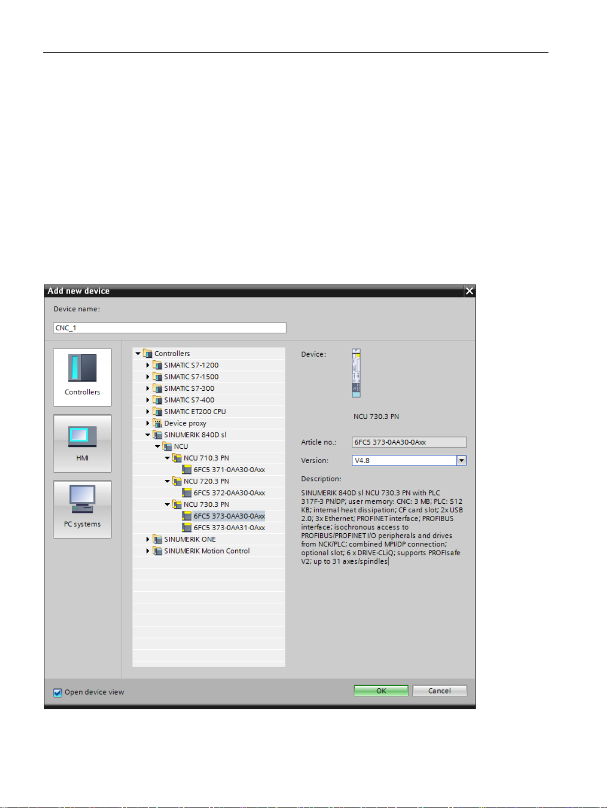
To insert a SINUMERIK NCU in the project view, proceed as follows:
1. Click "Add new device" in the project tree.
2. Click the "Controllers" button.
3. In the folder structure under "Controllers", expand the corresponding SINUMERIK device
family (e.g. SINUMERIK 840D sl) and required NCU and select these.
Figure 4-1 Selected NCU using the SINUMERIK 840D sl NCU 730.3 PN V4.8 as an example
SINUMERIK 840D sl STEP 7 Toolbox V17
26 Conguration Manual, 07/2021, 6FC5397-0GP40-0BA2
Page 27

4. Select the rmware version that matches the envisaged rmware version of the real NCU in
the "Version" drop-down list.
5. Conrm your selection with "OK".
Result
The SINUMERIK NCU is created as new device.
See also
Replacing a device or upgrading rmware (Page 32)
4.2 Insert NX module
Procedure
Conguring the NCU
4.2 Insert NX module
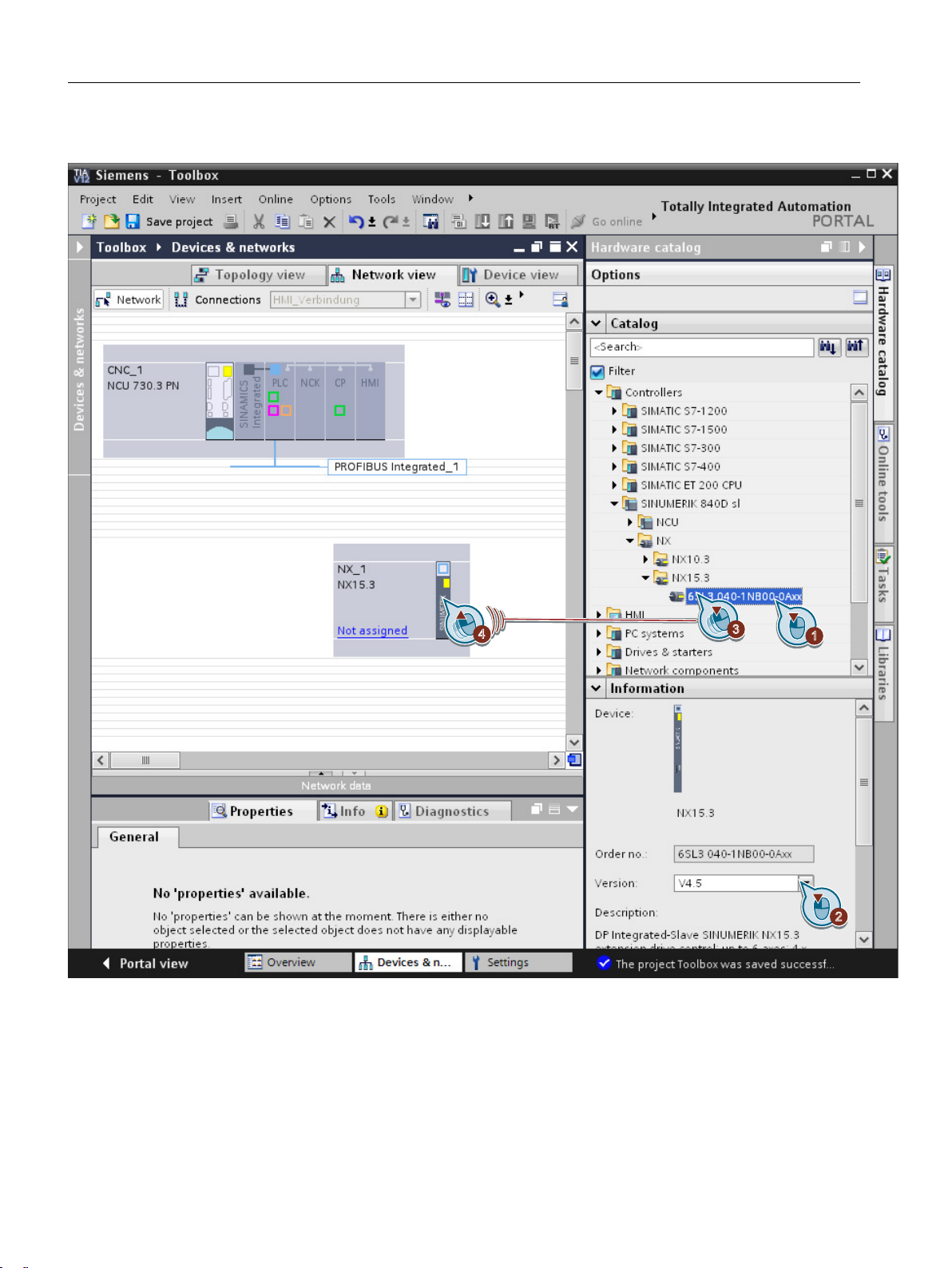
In order to insert an NX module into the project via the hardware catalog, proceed as follows:
1. In the network view, navigate in the hardware catalog to the folder "Controller >
SINUMERIK 840D sl > NX" and select, for example, NX15.3 .
2. You can select the rmware version of the NX module at "Information" in the hardware
catalog. This must match the rmware version of SINAMICS Integrated. Firmware versions of
the congured hardware and the real hardware must match.
SINUMERIK 840D sl STEP 7 Toolbox V17
Conguration Manual, 07/2021, 6FC5397-0GP40-0BA2 27
Page 28
Conguring the NCU
4.2 Insert NX module
3. Use drag-and-drop to move the NX module from the hardware catalog to the network view.
28 Conguration Manual, 07/2021, 6FC5397-0GP40-0BA2
SINUMERIK 840D sl STEP 7 Toolbox V17
Page 29
Conguring the NCU
4.2 Insert NX module
4. To connect the NX module with a master system, click "Not assigned" and select the master
system.
Note
Connection to DP Integrated
Note that the NX modules can only be connected to the DP Integrated of a SINUMERIK NCU,
and not to external PROFIBUS interfaces!
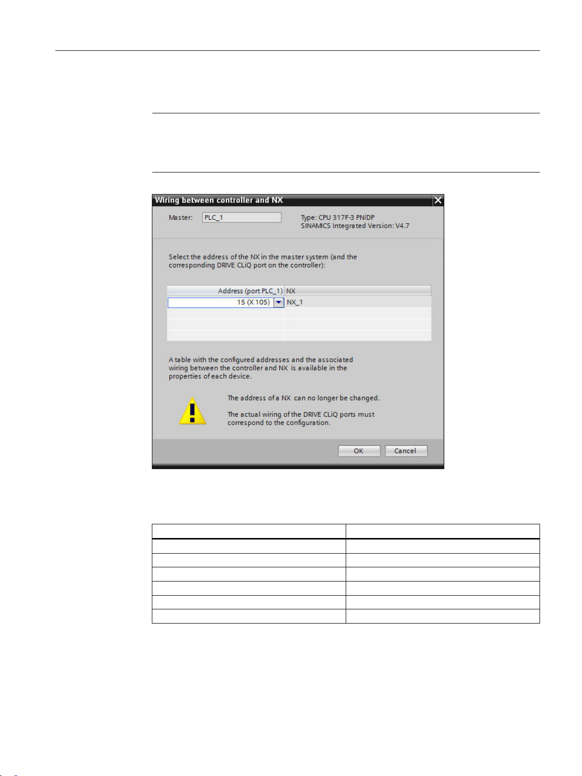
The NX is connected with the NCU and the "Wiring between control and NX" dialog opens.
5. In the "Wiring between control and NX" dialog, select the DP address of the NX in the master
system that matches your real wiring. The DP addresses of the NX modules are permanently
assigned to the DRIVE-CLiQ sockets of the NCU.
DP address of the NX in the master system DRIVE-CLiQ socket on the NCU
10 X100
11 X101
12 X102
13 X103
14 X104
15 X105
SINUMERIK 840D sl STEP 7 Toolbox V17
Conguration Manual, 07/2021, 6FC5397-0GP40-0BA2 29
Page 30

Conguring the NCU
4.2 Insert NX module
Note
This setting cannot be undone
Please note that once set, the DP address of an NX cannot be subsequently changed. The NX
modules must be connected to the DRIVE-CLiQ socket of the NCU in the real wiring that
corresponds to the permanently assigned DP address.
If you have incorrectly set the DP address of an NX, delete this NX from the project and add
a new one.
The DP address of the NX module is specied in accordance with your setting and the
appropriate I/O addresses of the telegrams are set automatically.
Note
Default I/O addresses of the telegrams
Depending on the set DP address, the appropriate I/O addresses of the telegrams are set
automatically.
Change this setting only when the I/O addresses of your telegrams dier from the default
setting!
You can also nd information on the wiring between NCU and NX in the properties of the DP
Integrated interface on the NCU and NX under "PROFIBUS address".
SINUMERIK 840D sl STEP 7 Toolbox V17
30 Conguration Manual, 07/2021, 6FC5397-0GP40-0BA2
Page 31

Result
Conguring the NCU
4.2 Insert NX module
The NX module has been inserted into the project and connected to an NCU.
Note
Handling the NX module
The NX module can be assigned to another NCU. Generally, the previous conguration of the NX
module is kept.
However, this cannot always be performed in individual cases. For example, it is possible that
changes must again be applied to the telegram conguration regarding the assignment to the
process image and organization block.
If the DP address of the NX module is specied, then the I/O addresses matching the default
setting on the NCK side are entered.
SINUMERIK 840D sl STEP 7 Toolbox V17
Conguration Manual, 07/2021, 6FC5397-0GP40-0BA2 31
Page 32

Conguring the NCU
4.3 Replacing a device or upgrading rmware
4.3 Replacing a device or upgrading rmware
4.3.1 Replacing the NCU
You can replace dierent NCUs. By replacing a device within the same device family, you can
change to another NCU with a dierent expansion stage, with a dierent rmware version and
other properties.
Rules for replacing an NCU
• It is not possible to replace an NCU with another controller of a dierent device family.
(You may be able to perform a migration.)
• It is not possible to replace an NCU with an NCU of the same project stage with the same or
previous rmware version.
• If you replace an NCU by another NCU, then automatically all of the integrated
subcomponents of the NCU (SINAMICS Integrated, PLC, NCK, CP, HMI) are also replaced.
• If you have connected NX modules to an NCU and replace the NCU, the connection between
the devices remains, provided the used interfaces exist on both NCUs. If the used interface
on the replaced NCU does not exist, the connection will be separated.
4.3.2 Replacing an NX
You can replace a device with a dierent NX type. The version of an NX is determined by the
version of the NCU. Correspondingly, for a connected NX, you can only replace the type: An
NX10.3 can be replaced by an NX15.3 and vice versa.
Rules for replacing an NX
If you replace NX10.3 with NX15.3, please note that NX10.3 only supports a maximum of three
servo axes, whereas NX15.3 supports up to six servo axes.
For more information about the conguration of the drive objects, see Adapting the number of
drives (Page 119)
SINUMERIK 840D sl STEP 7 Toolbox V17
32 Conguration Manual, 07/2021, 6FC5397-0GP40-0BA2
Page 33

4.3.3 Basic procedure
Note
Changing the rmware version of the congured NCU or NX
• Loading is possible if the rmware version of the congured and real hardware match.
• Loading is not possible if the rmware version of the hardware congured oine is newer
than the rmware version of the real hardware.
Otherwise it is possible that you congure version-dependent non-identiable properties in
the TIA Portal that the real hardware does not support.
• Loading is possible if the rmware version of the hardware congured oine is older than the
rmware version of the real hardware.
To replace the rmware version for a group (NCU with NX), the replacement on the NCU must
be initiated. Interconnected NXs are then also replaced automatically.
Procedure
Conguring the NCU
4.3 Replacing a device or upgrading rmware
To replace a device, proceed as follows:
1. Switch to the device view.
2. Select the device that you want to replace in the "<Select device>" drop-down list.
SINUMERIK 840D sl STEP 7 Toolbox V17
Conguration Manual, 07/2021, 6FC5397-0GP40-0BA2 33
Page 34

Conguring the NCU
4.3 Replacing a device or upgrading rmware
3. Right-click the device and then select "Replace device" in the shortcut menu.
The "Replace device" dialog opens.
4. Select the new device in the folder structure.
SINUMERIK 840D sl STEP 7 Toolbox V17
34 Conguration Manual, 07/2021, 6FC5397-0GP40-0BA2
Page 35

Result
Conguring the NCU
4.3 Replacing a device or upgrading rmware
5. Select the required rmware version in the "Version" drop-down list.
Note
Solving compatibility problems
If the two devices are not compatible or only have restricted compatibility, you can nd more
information in Section "Compatibility information".
If required, click "Cancel" and correct the problems before continuing.
6. Conrm the dialog with "OK".
The device has been replaced.
If you uploaded the rmware version, your telegram conguration was retained. Note that the
default telegram I/O addresses of telegram 701 have changed as of V4.7 SP2.
See also: Telegram conguration and I/O addressing schematics, Resetting telegrams
More information
More information on device replacement can be found in the information system of the TIA
Portal, keyword "Replacing".
SINUMERIK 840D sl STEP 7 Toolbox V17
Conguration Manual, 07/2021, 6FC5397-0GP40-0BA2 35
Page 36

Conguring the NCU
4.4 Establish the communication connection
4.4 Establish the communication connection
Procedure
To establish a communication connection between two devices, proceed as follows:
1. In the "Online" menu, select the "Accessible devices" command.
2. In the drop-down lists "Type of PG/PC interface" and "PG/PC interface", search for the interface
used.
If no devices are accessible at an interface, the connecting line between the PG/PC and the
device is interrupted. If devices are accessible, the connecting line is shown and the devices
accessible at the selected interface of the PG/PC are displayed in a list.
SINUMERIK 840D sl STEP 7 Toolbox V17
36 Conguration Manual, 07/2021, 6FC5397-0GP40-0BA2
Page 37

4.5 Load hardware conguration into the PLC
3. If you have connected a new device in the meantime, click the "Refresh" button to refresh the
list of accessible devices.
4. Using "Display", transfer to the project navigator the device that has been found in the
"Online accesses" folder.
The subfolder of the interface to which the selected device is connected is selected in the
project tree.
Note
Several identical devices
If several identical devices can be accessed from the PG, by clicking on the "Flash LED" button
you can then display which device corresponds to the entry in the list of accessible devices.
4.5 Load hardware conguration into the PLC
Requirement
Conguring the NCU
• The hardware conguration is compiled.
• A communication connection exists between the PG/PC (TIA Portal) and the NCU.
Note
Loading congurations to simulated environments
If you want to use the conguration in a simulated environment, you must activate the
simulation capability in the project properties before you load the conguration into the
simulated environment or compile the hardware/software.
Note
General reset before loading into a PLC with Safety Integrated plus (F-PLC)
If the actual hardware has been operated in Safety Integrated plus (F-PLC) mode and you now
want to load a congured hardware conguration with changed Safety Integrated mode, you
must perform a general reset of the PLC prior to the loading.
SINUMERIK 840D sl STEP 7 Toolbox V17
Conguration Manual, 07/2021, 6FC5397-0GP40-0BA2 37
Page 38

Conguring the NCU
4.5 Load hardware conguration into the PLC
Procedure
Proceed as follows to load the congured hardware conguration into the NCU:
1. In the project navigation, right-click the device name, e.g. "CNC_1", and select the "Hardware
conguration" command in the "Download to device" shortcut menu.
Note
Scope of the data to be downloaded
Alternatively, you can select one of the other commands to start downloading additional
data to the NCU in this step.
See TIA Portal help, keyword "General information on download".
The "Extended download" dialog opens.
Figure 4-2 Dialog using the PLC of a SINUMERIK 840D sl as an example
2. Make the following settings in the "Extended download" dialog:
– PG/PC interface: Network card used, e.g. "Intel[R] Ethernet Connection I217-V"
SINUMERIK 840D sl STEP 7 Toolbox V17
38 Conguration Manual, 07/2021, 6FC5397-0GP40-0BA2
Page 39

Conguring the NCU
4.5 Load hardware conguration into the PLC
– Connection with interface/subnet: Specic interface on the NCU or "Try all interfaces"
3. Click on "Start search" and then select the found PLC from "Compatible nodes in the target
subnet". Alternatively, you can specify an IP address directly in the "Compatible nodes in the
target subnet" list in the "Address" column.
4. Conrm the download with "Load".
The "Download preview" dialog opens.
Figure 4-3 "Download preview" dialog
Note
Consistency check
Before the loading, the consistency of the download is checked. This means that a check is
made as to whether the parameterized hardware of the TIA Portal project matches the
hardware that has been actually installed.
Note
Adapt the IP address?
If the IP address of your PG/PC is located in a dierent subnet than the PLC, a dialog box is
displayed as to whether the IP address in the PG/PC should be adapted.
5. In the "Download preview" dialog, check the settings and click "Load" to conrm the input.
SINUMERIK 840D sl STEP 7 Toolbox V17
Conguration Manual, 07/2021, 6FC5397-0GP40-0BA2 39
Page 40

Conguring the NCU
4.6 Creating SINUMERIK PLC archives
Result
The PLC is stopped and the hardware conguring is loaded into the PLC. The "Results of the
loading action" dialog opens and displays the status of the loading action. The dialog restarts the
PLC after completion, provided the "Start" checkbox has not been deactivated.
4.6 Creating SINUMERIK PLC archives
4.6.1 Creating a SINUMERIK PLC archive
Introduction
Unlike TIA Portal project archives (*.zap*), SINUMERIK PLC archives (*.arc) contain precompiled
commissioning data that you can import directly to the NCU (e.g. with SINUMERIK Operate).
A SINUMERIK archive oers the following possibilities:
• Direct image of the data of a PLC taken into operation in a le
• Simplication of the series commissioning
• Commissioning of the PLC with the SINUMERIK archive directly on the NCU without using a
PG/PC, TIA Portal or STEP 7
• Transfer of the data to the NCU without establishing an online connection to the actual
hardware
SINUMERIK archives (*.arc) have nothing in common with TIA Portal project archives (*.zap*).
TIA Portal project archives are compressed les, each of which contains a complete project,
including the complete folder structure of the project. (See: Online help, keyword "TIA Portal
project archive").
You can create a PLC archive with the SINUMERIK Toolbox and load it to the NCU (e.g. with
SINUMERIK Operate) in order to simplify the actual commissioning.
You can create the following SINUMERIK archives:
Archive type Command in the TIA
Portal
PLC hardware upgrade ar‐
chive (Page 44)
PLC commissioning ar‐
chive (Page 46)
PLC reload archive
(Page 48)
Only hardware...
Hardware and all pro‐
gram blocks...
Selected program
blocks...
Data included
• Hardware data (SDB) of the PLC
• Hardware data (SDB) of the PLC
• Program blocks of the PLC
• Hardware data (SDB) of the CP
• Program blocks of the PLC
SINUMERIK 840D sl STEP 7 Toolbox V17
40 Conguration Manual, 07/2021, 6FC5397-0GP40-0BA2
Page 41

Note
Editing SINUMERIK archives (.arc)
After you have created a SINUMERIK archive, you can open and edit it with various tools.
See: External tools for SINUMERIK archives (Page 44)
Note
Handling of F-blocks for SINUMERIK archives
Because F-blocks must always be saved together with the associated hardware conguration, Fblocks cannot be saved in reload archives.
Further information
• General information on NCU series commissioning archives can be found in Section "Saving
Conguring the NCU
4.6 Creating SINUMERIK PLC archives
and managing data" of the "SINUMERIK 840D sl, SINAMICS S120 Commissioning CNC:NCK,
PLC, Drive for TIA" Commissioning Manual.
• Information about the dierences of the archives that were created with STEP 7 V5.x is
available at "Handling SINUMERIK archives".
SINUMERIK 840D sl STEP 7 Toolbox V17
Conguration Manual, 07/2021, 6FC5397-0GP40-0BA2 41
Page 42

Conguring the NCU
4.6 Creating SINUMERIK PLC archives
Overview
You can create SINUMERIK archives in various ways:
• In the menu bar at "Tools"
• In the shortcut menu of the NCU or PLC:
Figure 4-4 Creating a SINUMERIK archive
SINUMERIK 840D sl STEP 7 Toolbox V17
42 Conguration Manual, 07/2021, 6FC5397-0GP40-0BA2
Page 43

4.6.2 Available SINUMERIK archive types
There are dierent types of archives which you can create in dierent ways. Essentially, you
cannot use the TIA Portal to create archives that contain NC, drive or HMI data. However, you can
save a nely granular selection of translated program blocks as an archive in the TIA Portal with
the "PLC reload archive".
Conguring the NCU
4.6 Creating SINUMERIK PLC archives
Archive type Command in the TIA
Portal
NCU commissioning ar‐
chive
PLC commissioning ar‐
chive (Page 46)
PLC hardware upgrade ar‐
chive (Page 44)
PLC reload archive
(Page 48)
Complete archive - <Ctrl> + <Alt> + S
Original status archive - Softkey "Commission‐
- Softkey "Commission‐
Hardware and all pro‐
gram blocks...
Only hardware...
Selected program
blocks...
Command in SINU‐
MERIK Operate
ing archive", option
button "Create commis‐
sioning archive"
Softkey "Commission‐
ing archive", option
button "Create commis‐
sioning archive"; only
enable "PLC data" in the
dialog
Softkey "Commission‐
ing archive", option
button "Create PLC
hardware upgrade ar‐
chive (only SDBs)"
-
ing archive", option
button "Create archive
original status"
Data contained
The contained data can be congured as fol‐
lows in the dialog:
• NC data
– With or without compensation data
– With or without compile cycles
• PLC data (all or none)
• Drive data (ACX format or ASCII format)
• HMI data (all HMI data or a congurable se‐
lection)
• Hardware data (SDB) of the PLC
• Program blocks of the PLC
• Hardware data (SDB) of the CP
• Hardware data (SDB) of the PLC
• Hardware data (SDB) of the CP
• Program blocks of the PLC
(congurable in the dialog)
All data (not congurable)
Original status (factory setting) of all subcom‐
ponents or a selection of specic subcompo‐
nents and data (congurable in the dialog)
SINUMERIK 840D sl STEP 7 Toolbox V17
Conguration Manual, 07/2021, 6FC5397-0GP40-0BA2 43
Page 44

Conguring the NCU
4.6 Creating SINUMERIK PLC archives
Note
Distinguishing between TIA Portal project archives and SINUMERIK archives
SINUMERIK archives (*.zap) have nothing in common with TIA Portal project archives (*.arc):
• SINUMERIK archives contain precompiled commissioning data that you can import directly to
the NCU.
• TIA Portal project archives are compressed les, each of which contains a complete project,
including the complete folder structure of the project.
See: TIA Portal online help, search term "TIA Portal project archive".
4.6.3 External tools for SINUMERIK archives
Overview
Various tools are available to open and edit the created SINUMERIK archives:
Tool Purpose Available from
SinuCom ARC Editing of SINUMERIK archives SinuCom commissioning/service tools in
the SIEMENS Industry Mall (https://
eb.automation.siemens.com/
mall/en/us/Catalog/Product/
6FC5250-7AY00-7AG0)
Create MyCong Extensive software, including functions
such as:
• Data comparison of SINUMERIK ar‐
chives
• Manipulation of SINAMICS data in
drive archives
• Creation of a SINAMICS archive with
dened topology
Create MyCong in the SIEMENS Indus‐
try Mall (https://
eb.automation.siemens.com/
mall/en/us/Catalog/Products/10167653)
4.6.4 Creating a PLC hardware upgrade archive
Requirement
• The data carrier to be used or storage location is available and has sucient storage space.
SINUMERIK 840D sl STEP 7 Toolbox V17
44 Conguration Manual, 07/2021, 6FC5397-0GP40-0BA2
Page 45

Procedure
Conguring the NCU
4.6 Creating SINUMERIK PLC archives
To create a hardware upgrade archive, proceed as follows:
1. In the project tree, right-click the device name, e.g. "CNC_1", and select "Create SINUMERIK
archive > Hardware only" in the shortcut menu.
The "Create SINUMERIK archive" dialog opens.
Figure 4-5 "Create SINUMERIK archive" dialog with hardware
2. Make the required settings:
Element Purpose
File name Enter the desired le name of the SINUMERIK archive in the text eld.
File extensions cannot be changed
The le extension (.arc) is not displayed and cannot be changed.
Path Click Browse and select a directory, or enter the directory directly.
Default storage location for data export
The used path is shown as the default setting the next time you export an archive.
To specify the default setting for the data export in the settings, switch to "General >
General > Data exchange > Storage location for data export" in the settings.
Author Name of the author or a person responsible for the project.
The default setting corresponds to the setting of the user name in the TIA Portal under:
"Extras > Settings > General > General settings > User name".
Comment Input of a comment for the SINUMERIK archive.
As default setting, the comment eld contains an entry indicating whether the archive
contains only hardware or hardware and all program blocks.
Press the shortcut keys <Shift+Return> to insert a line break.
3. Click "Create archive" to conrm your input.
Result
The SINUMERIK archive is created and stored in the path that you have specied.
SINUMERIK 840D sl STEP 7 Toolbox V17
Conguration Manual, 07/2021, 6FC5397-0GP40-0BA2 45
Page 46

Conguring the NCU
4.6 Creating SINUMERIK PLC archives
4.6.5 Creating a PLC commissioning archive
Requirement
• If possible, the "Program blocks" folder should not contain any program blocks of not
activated axes/spindles or the tool management.
You can also save unused program blocks in the archive, although this extends the time
required for creating and loading the archive.
• The data carrier to be used or storage location is available and has sucient storage space.
Note
Handling of F-blocks for SINUMERIK archives
The handling of F-blocks depends on the used Safety Integrated mode:
• If Safety Integrated is inactive or Safety Integrated (SPL) is active, F-blocks are not stored in
the SINUMERIK archive.
• In Safety Integrated plus (F-PLC) mode, F-blocks are saved in PLC commissioning archives.
Note the additional information in the Readme le for SINUMERIK Toolbox: "Start > Siemens
Automation > Documentation > Readmes > English".
SINUMERIK 840D sl STEP 7 Toolbox V17
46 Conguration Manual, 07/2021, 6FC5397-0GP40-0BA2
Page 47

Procedure
Conguring the NCU
4.6 Creating SINUMERIK PLC archives
To create a PLC commissioning archive, proceed as follows:
1. In the project tree, right-click the device name, e.g. "CNC_1", and select "Create SINUMERIK
archive > Hardware and all program blocks" in the shortcut menu.
The "Create SINUMERIK archive" dialog opens.
Figure 4-6 "Create SINUMERIK archive" dialog with hardware data and program blocks
2. Make the required settings:
Element Purpose
File name Enter the desired le name of the SINUMERIK archive in the text eld.
File extensions cannot be changed
The le extension (.arc) is not displayed and cannot be changed.
Path Click Browse and select a directory, or enter the directory directly.
Default storage location for data export
The used path is shown as the default setting the next time you export an archive.
To specify the default setting for the data export in the settings, switch to "General >
General > Data exchange > Storage location for data export" in the settings.
Author Name of the author or a person responsible for the project.
The default setting corresponds to the setting of the user name in the TIA Portal under:
"Extras > Settings > General > General settings > User name".
Comment Input of a comment for the SINUMERIK archive.
As default setting, the comment eld contains an entry indicating whether the archive
contains only hardware or hardware and all program blocks.
Press the shortcut keys <Shift+Return> to insert a line break.
3. Click "Create archive" to conrm your input.
Result
The SINUMERIK archive is created and stored in the path that you have specied.
SINUMERIK 840D sl STEP 7 Toolbox V17
Conguration Manual, 07/2021, 6FC5397-0GP40-0BA2 47
Page 48

Conguring the NCU
4.6 Creating SINUMERIK PLC archives
4.6.6 Creating a PLC reload archive
You can save the program blocks of the PLC as reload archive in the TIA Portal.
Note
F-blocks are not saved in reload archives
The F-blocks used in the SINUMERIK Safety Integrated plus (F-PLC) mode are not saved in reload
archives.
If you want to save F-blocks in a SINUMERIK archive, you can save them together with the
associated hardware conguration in a PLC commissioning archive.
Note
In the PLC reload archive, existing data blocks overwrite any CPU DBs during reading in
If you import into a PLC reload archive a CPU DBs that already exists on the control system, the
CPU DBs on the control system will always be overwritten. Therefore the option "Overwrite
existing blocks with identical number on the PLC for import" does not aect CPU-DB.
Therefore, do not store data blocks that already exist on the NCU as CPU DB in the PLC reload
archive.
Requirement
If you have already overwritten CPU DBs, you can nd further information in the information
system, keyword "Inconsistency in data blocks".
• If possible, the "Program blocks" folder should not contain any program blocks of not
activated axes/spindles or the tool management.
Although you can save unused program blocks in the archive, this extends the time required
for creating and loading the archive.
• The data carrier to be used or storage location is available and has sucient storage space.
SINUMERIK 840D sl STEP 7 Toolbox V17
48 Conguration Manual, 07/2021, 6FC5397-0GP40-0BA2
Page 49

Procedure
Conguring the NCU
4.6 Creating SINUMERIK PLC archives
To create a reload archive, proceed as follows:
1. You have several ways of selecting the program blocks to be archived:
– Select the desired program blocks in the project tree or in the project tree overview. Then
right-click one of the selected program blocks.
You can change the actual program blocks to be exported later in the "Create SINUMERIK
archive" dialog.
– Right-click the program blocks folder of the PLC or a higher-level folder.
You can select the program blocks to be exported later in the "Create SINUMERIK archive"
dialog.
2. Click "Selected program blocks" in the "Create SINUMERIK archive" in the shortcut menu.
The "Create SINUMERIK archive" dialog opens.
Figure 4-7 "Create SINUMERIK archive" dialog with expanded "Block selection" section
SINUMERIK 840D sl STEP 7 Toolbox V17
Conguration Manual, 07/2021, 6FC5397-0GP40-0BA2 49
Page 50

Conguring the NCU
4.6 Creating SINUMERIK PLC archives
3. Make the required settings:
Element Purpose
Block selection In the "Block selection" section, you can check your selection or select the
File name Enter the desired le name of the SINUMERIK archive in the text eld.
Path Click Browse and select a directory, or enter the directory directly.
Author Name of the author or a person responsible for the project.
Comment Input of a comment for the SINUMERIK archive.
Overwrite existing
blocks with identical
number on the PLC
for import
Restart the PLC after
import of the new
program blocks
program blocks to be saved.
If you have organized program blocks as groups, they are displayed as an
expandable folder in the block selection.
File extensions cannot be changed
The le extension (.arc) is not displayed and cannot be changed.
Default storage location for data export
The used path is shown as the default setting the next time you export an
archive.
To specify the default setting for the data export in the settings, switch to
"General > General > Data exchange > Storage location for data export" in the
settings.
The default setting corresponds to the setting of the user name in the TIA
Portal under: "Extras > Settings > General > General settings > User name".
If the "Insert selected blocks as comment" check box is activated, all contained
program blocks are entered automatically with symbolic name and block
number.
Press the shortcut keys <Shift+Return> to insert a line break.
If the check box is activated, existing program blocks with the same block
number will be replaced on the NCU during the import of the archive.
If the check box is deactivated, any program blocks of the archive with the
same block number will not be imported.
If the check box is activated, the PLC will be restarted automatically after
importing the archive.
You can also deactivate the check box and, for example, make other installa‐
tion or commissioning work before you manually restart the PLC or the com‐
plete NCU.
4. Click "Create archive" to conrm your input.
Result
The SINUMERIK archive is created and stored in the path that you have specied.
SINUMERIK 840D sl STEP 7 Toolbox V17
50 Conguration Manual, 07/2021, 6FC5397-0GP40-0BA2
Page 51

Programming the PLC
5.1 General information about the PLC program
5.1.1 Introduction
The PLC program is constructed modularly. It comprises the two parts:
• PLC basic program
The PLC basic program organizes the exchange of signals and data between the PLC user
program and the NCK, HMI, and machine control panel components.
Use the appropriate PLC basic program depending on the rmware version of an NCU.
– SINUMERIK 840D sl PLC basic program V4.5.x.x
– SINUMERIK 840D sl PLC basic program V4.7.x.x
– SINUMERIK 840D sl PLC basic program V4.8.x.x
– SINUMERIK 840D sl PLC basic program V4.91.x.x
– SINUMERIK 840D sl PLC basic program V4.92.x.x
– SINUMERIK 840D sl PLC basic program V4.93.x.x
5
– SINUMERIK 840D sl PLC basic program V4.94.x.x
– SINUMERIK 840D sl PLC basic program V4.95.x.x
• PLC user program
The PLC user program is the user-specic part of the PLC program by which the PLC basic
program has been augmented or extended.
5.1.2 Execution structure
Overview
The following organization blocks contain the entry points for the appropriate parts of the PLC
basic program (and user program):
• OB100 [OB100] (Cold restart)
• OB1 [OB1] (Cyclic execution)
• OB40 [OB40] (Process interrupt)
• Asynchronous errors
– OB82 [OB82] (Diagnostics alarm)
– OB86 [OB86] (Module failure)
SINUMERIK 840D sl STEP 7 Toolbox V17
Conguration Manual, 07/2021, 6FC5397-0GP40-0BA2 51
Page 52

&\FOLFSURFHVVLQJ
8VHUSURJUDP
8VHUSURJUDP
5HVWDUW
+DUGZDUHLQWHUUXSW
8VHUSURJUDP
6WDUGHOWD
(UURUDQGRSHUDWLQJ
PHVVDJHV
5HDGZULWHWDJ
3,VHUYLFHV
6SLQGOHFRQWURO
'LVSOD\FRQWURO
+7
%DVLFSURJUDP
%DVLFSURJUDP
'LDJQRVWLFLQWHUUXSW
8VHUSURJUDP
%DVLFSURJUDP
5DFNIDLOXUH
8VHUSURJUDP
%DVLFSURJUDP
7RROPDQDJHPHQW
0&3VLJQDOV
+7bVLJQDOV
%DVLFSURJUDP
6WDUW$683
)&
)&
)%)%)%)%
)&
)&
)&
)&)&)&
)&)&)&)&
)&
)%
2%
2%
2%
)&
2%
)&
2%
)&
Programming the PLC
5.1 General information about the PLC program
The RUN_UP [FB1] function block is the startup block of the PLC basic program. The call of
RUN_UP [FB1] in the OB100 [OB100] must be supplied with data.
The following gure illustrates the structure of the PLC program:
52 Conguration Manual, 07/2021, 6FC5397-0GP40-0BA2
Figure 5-1 Structure of the PLC program
SINUMERIK 840D sl STEP 7 Toolbox V17
Page 53

Cyclic operation (OB1)
From a chronological viewpoint, the PLC basic program runs ahead of the PLC user program. The
complete processing of the NCK-PLC interface is carried out in cyclic mode. A cyclic monitoring
function is activated between PLC and NCK once boot-up and the rst OB1 cycle have been
completed. A PLC failure produces the "2000 Sign-of-life monitoring PLC" alarm in
SINUMERIK Operate.
Start-up behavior of the PLC
The PLC always starts up in RESTART mode, i.e. the PLC operating system runs OB100 after
initialization and starts cyclic operation at the beginning of OB1. No return is made to the
interruption point (for example, in the event of a power failure).
There are both retentive and non-retentive areas for the markers, timers and counters. The areas
are contiguous and are divided by a parameterizable limit, where the area with the higher-value
address range is dened as the non-retentive area. Data blocks are always retentive.
RESTART start type (OB100)
If the retentive area has no battery backup (backup battery is empty) start-up is prevented. The
following operations are performed during a cold restart:
Programming the PLC
5.1 General information about the PLC program
• UStack, BStack and non-retentive ags, timers and counters are deleted
• The process output image (POI) is deleted
• Process and diagnostics alarms are canceled
• The system status list is updated
• Parameterization objects of modules (from SDB100 onwards) are evaluated or default
• Cold restart (OB100) is executed
• The process input image (PII) is imported
• The command output inhibit (BASP) is canceled
Further information
Block descriptions and other information about the PLC basic program are provided in the PLC
Function Manual.
parameters are output to all modules in single-processor mode
SINUMERIK 840D sl STEP 7 Toolbox V17
Conguration Manual, 07/2021, 6FC5397-0GP40-0BA2 53
Page 54
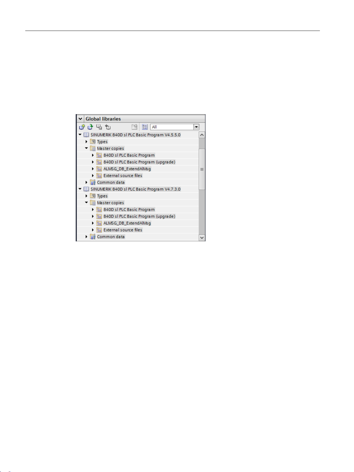
Programming the PLC
5.1 General information about the PLC program
5.1.3 Using copy templates
Introduction
The "Global libraries" folder of the "Libraries" TaskCard contains the system library of the
SINUMERIK PLC program for your device version: "SINUMERIK 840D sl PLC basic program
V4.x.x.x".
Figure 5-2 Master copies of the SINUMERIK PLC program
Under the "Master copies" folder there are four subfolders with dierent contents. You can copy
the contents of these subfolders in their entirety or you can copy the individual objects as
needed.
• Using the Ctrl or shift key, you can select several objects of the same type and then copy them.
• If you copy a master copies folder in its entirety (e.g. "840D sl PLC BP"), the folder structure
is imported, i.e. new groups (subfolders) are created (Page 76) in your "Program blocks"
folder.
SINUMERIK 840D sl STEP 7 Toolbox V17
54 Conguration Manual, 07/2021, 6FC5397-0GP40-0BA2
Page 55

5.1 General information about the PLC program
Table 5-1 Use and content of the master copies of the PLC basic program
Folder Purpose Contents
840D sl PLC Ba‐
sic Program
840D sl PLC Ba‐
sic Program (up‐
grade)
This master copy is intended
to create a completely new
project.
This master copy is used to
upgrade blocks after the rm‐
ware version of an NCU is up‐
dated, i.e. if you have carried
out a device replacement
(Page 32) or a migration.
The master copy contains all the blocks that you require for the maximum
conguration (31 axes, 10 channels).
Use of axis/channel DB
If your machine is using fewer axes or channels, you can either copy only the
required blocks or you can delete the blocks that are not required in the
project tree after copying.
If you have blocks in your project that are not required, this increases,
for example, the time required for the loading or export of the PLC symbols.
Use of ALMSG_DB [DB2]
This master copy contains ALMSG_DB [DB2] in the variant Exten‐
dAlMsg=False.
The used DB2 variant must match in the startup for parameterization of the
RUN_UP [FB1] in OB100 [OB100] (parameter ExtendAlMsg).
This master copy contains all the know-how-protected blocks that you re‐
quire for the maximum conguration (31 axes, 10 channels).
Blocks to be changed by the user are not included (no organization blocks
and not FC12 [FC12], Diagnose [FB29], DB4 [DB4], DB5 [DB5]).
Use of axis/channel DB
If your machine is using fewer axes or channels, you can either copy only the
required blocks or you can delete the blocks that are not required in the
project tree after copying.
If you have blocks in your project that are not required, this increases,
for example, the time required for the loading or export of the PLC symbols.
Use of ALMSG_DB [DB2]
This master copy contains ALMSG_DB [DB2] in the variant Exten‐
dAlMsg=False.
The used DB2 variant must match in the startup for parameterization of the
RUN_UP [FB1] in OB100 [OB100] (parameter ExtendAlMsg).
Programming the PLC
SINUMERIK 840D sl STEP 7 Toolbox V17
Conguration Manual, 07/2021, 6FC5397-0GP40-0BA2 55
Page 56

Programming the PLC
5.1 General information about the PLC program
Folder Purpose Contents
ALMSG_DB_Ex‐
tendAlMsg
External source
les
You need this master copy if
you use the PLC alarm exten‐
sion via AL_MSG [FC10] (Ex‐
tendAlMsg=True).
Otherwise you use the DB2
variant "ExtendAlMsg=False",
which is contained in the two
above-named master copies
folders.
Contains master copies for dif‐
ferent external sources (STL).
You can copy these sources
into the folder "External sour‐
ces", e.g. under "CNC_1 >
PLC_1 > External sources".
You edit objects in the "Exter‐
nal sources" folder using an
external text editor, e.g. Mi‐
crosoft Editor.
See also: Create blocks from
external sources (Page 77)
This master copy contains ALMSG_DB [DB2] in the variant Exten‐
dAlMsg=True (PLC alarm extension via AL_MSG [FC10]).
The used DB2 variant must match in the startup for parameterization of the
RUN_UP [FB1] in OB100 [OB100] (parameter ExtendAlMsg).
Contains the following master copies, from which you can generate the
blocks named below:
• bhg_db_awl
– strdat [DB<xy>]
• diagnose.awl
– FB29 [FB29]
– DB80 [DB80]
– DB81 [DB81]
– FC99 [FC99]
• gpob840d.awl
– OB1 [OB1]
– OB100 [OB100]
– OB40 [OB40]
– OB82 [OB82]
– OB86 [OB86]
• mdeclist.awl
– DB75 [DB75]
SINUMERIK 840D sl STEP 7 Toolbox V17
56 Conguration Manual, 07/2021, 6FC5397-0GP40-0BA2
Page 57

Programming the PLC
5.1 General information about the PLC program
Note
Selecting the appropriate master copy for ALMSG_DB [DB2]
There are 2 dierent variants of the block ALMSG_DB [DB2]. The used DB2 variant (ALMSG_DB
[DB2]) must match in the startup for parameterization of the RUN_UP [FB1] in OB100 [OB100]
(parameter ExtendAlMsg).
• DB2 variant "ExtendAlMsg=False"
This variant is contained in the master copies folders "840D sl PLC Basic Program" and "840D
sl PLC Basic Program (upgrade)".
If you use the previous procedure (default value of the parameter ExtendAlMsg in RUN_UP
[FB1]), you do not need to explicitly copy the "ALMSG_DB_ExtendAlMsg" master copy.
• DB2 variant "ExtendAlMsg=True"
This variant is exclusively contained in the separate master copies folder
"ALMSG_DB_ExtendAlMsg".
If you use the extension of the PLC alarms via AL_MSG [FC10], you must use the right master
copy, i.e. copy it separately into your "Program blocks" folder.
Further information about the extension of the PLC alarms via AL_MSG [FC10] is available under
the keyword "ExtendAlMsg" in the Basic Functions Manual, in particular, in the "Extensions of the
PLC alarms via block FC 10" section.
Further information
• General information on handling libraries in the TIA Portal can be found in the TIA Portal
online help, Section "Using libraries".
• Block descriptions and other information about the PLC basic program are provided in the PLC
Function Manual.
5.1.4 Block listing as table
In the following, you will nd a list of all of the blocks of the SINUMERIK PLC basic program that
are included in the supplied master copy "840D sl PLC Basic Program".
The master copy "840D sl PLC Basic Program (upgrade)" contains the same blocks, except for
blocks with user-specic adaptations.
More information
• Information about other blocks of the basic program (e.g. blocks generated at runtime on the
NCU) or the operational principle of the basic program is contained in the Function Manual
SINUMERIK 840D sl / 828D Basic Functions.
• Information about the changed handling of specic blocks compared with STEP 7 V5.x is
available in the "Migrating SINUMERIK projects" help.
SINUMERIK 840D sl STEP 7 Toolbox V17
Conguration Manual, 07/2021, 6FC5397-0GP40-0BA2 57
Page 58

Programming the PLC
5.1 General information about the PLC program
Table 5-2 Organization blocks (OB)
Address Name Description Called PLC basic pro‐
gram block
OB1 OB1 Cycle OBs are higher-level logic blocks in the program which are cycli‐
cally processed and in which you can program instructions or call addi‐
tional blocks.
OB40 OB40 Hardware interrupt OBs interrupt the cyclic program processing due to
a hardware event.
OB82 OB82 Diagnostic error interrupt OBs interrupt the cyclic execution of the pro‐
gram if the diagnostic-capable module for which the diagnostic inter‐
rupt was enabled detects an error.
OB86 OB86 A rack or station failure OB is called, for example, in the event of failure
of a rack or station in the distributed I/O.
OB100 OB100 Startup OBs are processed once when the mode of the CPU switches
from STOP to RUN. After execution of the startup OB, the execution of
the cycle OB is started.
Table 5-3 Function blocks (FBs)
GP_HP [FC2]
GP_PRAL [FC3]
GP_DIAG [FC5]
GP_DIAG [FC5]
RUN_UP [FB1] with
gp_par [DB7]
Address Icon Meaning
FB1 RUN_UP The block congures and initializes the basic program, starts synchronization
between PLC and NCK, is called in OB100 with instance DB gp_par [DB7].
FB2 GET The block is used for reading NC tags.
FB3 PUT The block is used for writing NC tags.
FB4 PI_SERV The block is used for starting PI services.
FB5 GETGUD The block is used for reading global user data (GUD) from the NC and for
determining the GUD tag address.
FB7 PI_SERV2 The block is used for starting PI services that are dened in PI [DB16].
FB9 M2N The block is used for switching over operating components (MCP/OP) which
are connected with one or several control modules NCU; uses the signals
from MMC [DB19].
FB10 SI_relay Safety Integrated (SPL) block: Safety relay
FB11 SI_BrakeTest Safety Integrated (SPL) block: Brake test
FB21 Powerride Block to control a Powerride rotary/push switch.
FB29 Diagnostics Diagnostic routines for the PLC user program with logging of signal states
and signal changes.
Table 5-4 Functions (FCs)
Address Icon Meaning
FC2 GP_HP The block processes the cyclic part of the basic program, is called at the
beginning of OB1.
FC3 GP_PRAL The block processes the block-synchronous part of the basic program,
is called at the beginning of OB40.
FC5 GP_DIAG The block is used to record module disruptions and failures, is called at
the beginning of the following OBs: OB82, OB83, OB86.
SINUMERIK 840D sl STEP 7 Toolbox V17
58 Conguration Manual, 07/2021, 6FC5397-0GP40-0BA2
Page 59

Programming the PLC
5.1 General information about the PLC program
Address Icon Meaning
FC6 TM_TRANS2 The block transfers position and status information of the tools to the
tool management interface in connection with Multitool.
FC7 TM_REV The block acknowledges an implemented tool change of a turret to the
tool management interface.
FC8 TM_TRANS The block transfers position and status information of the tools to the
tool management interface.
FC9 ASUB The block starts asynchronous subprograms, the prerequisite is that it
must be selected and parameterized by an NC program or by the PI
service ASUP.
FC10 AL_MSG The block evaluates the signals entered in DB2, generates incoming
and outgoing error and operating messages of the operating software
and acknowledges error messages. Optionally, inuencing of the block
and stop signals can commence.
FC12 FC12 Call interface for users for auxiliary functions, the block is called on an
event-driven basis in the basic program when new auxiliary functions
are available.
FC13 BHGDisp The block handles the display control for the handheld unit (HHU or
HT 2).
FC17 Ydelta The block is used for star-delta changeover for digital main spindle
drives.
FC18 SpinCtrl The block controls axes and spindles from the user program.
FC19 MCP_IFM The block is used for transferring data from the machine control panel
(MCP milling version) to the NC/PLC interface.
FC21 Transfer The block is used for high-speed data exchange between PLC and NCK.
FC22 TM_DIR The blocks provides the shortest path and direction of motion for po‐
sitioning a tool magazine or turret (indexing axis).
FC24 MCP_IFM2 The block is used for transferring data from the machine control panel
(MCP milling version compact) to the NC/PLC interface.
FC25 MCP_IFT The block is used for transferring data from the machine control panel
(MCP turning version) to the NC/PLC interface.
FC26 HPU_MCP The block is used for transferring data of the HT 8 to the NC/PLC inter‐
face.
FC27 OpUnitWriteRecord Block writes a data set to a modular MCP
FC1005 FC1005 Block transfers data to Ethernet CP.
FC1006 FC1006 Block receives data from Ethernet CP.
SINUMERIK 840D sl STEP 7 Toolbox V17
Conguration Manual, 07/2021, 6FC5397-0GP40-0BA2 59
Page 60

Programming the PLC
5.1 General information about the PLC program
Table 5-5 Data blocks (DBs)
Address Icon Meaning
DB2 ALMSG_DB Interface between user program and AL_MSG [FC10], contains bit
arrays for blocking and stop signals as well as error and operating
messages.
Comment: If you use the DB2 variant "ExtendAlMsg = True", you must
copy it from the separate master copies folder "ALMSG_DB_Exten‐
dAlMsg". The other folders contain the variant "ExtendAlMsg = False".
DB4 DB4 Block contains conguration data for tool management and the pa‐
rameterization of the alarms for the bit arrays in the ALMSG_DB [DB2]
as error or operating message for the DB2 variant "ExtendAlMsg =
False".
DB5 DB5 Interface between user program and AL_MSG [FC10], contains the
parameterization of the alarms for the bit arrays in the ALMSG_DB
[DB2] as error or operating message for the DB2 variant "Exten‐
dAlMsg = True".
DB7 gp_par Instance DB from RUN_UP [FB1]. Contains parameters for congur‐
ing operating components and other parameters of the basic pro‐
gram.
DB8 DB8 DB only for internal use in the basic program.
DB10 NC Interface between user program and NC, contains signals from/to the
NC, PLC and operating software.
DB11 Mode group Interface between user program and mode groups, contains signals
from/to the NC, PLC and operating software.
DB15 DB15 General communication
DB16 PI Interface for PI_SERV2 [FB7], contains denitions for all available PI
services.
DB18 SPL Safety Integrated data (SPL)
DB19 MMC Interface for PI_SERV2 [FB7], contains denitions for all available PI
services.
DB21...DB30 Chan1...Chan10 Interface between user program and channel, contains signals from/
to channel 1...10.
DB31...DB61 Axis1...Axis31 Interface between user program and axis/spindle, contains signals
from/to axis/spindle 1...31.
DB71 TMLoadIF Interface between user program and tool management, contains
signals from/to Load/Unload magazine
DB72 TMSpindleIF Interface between user program and tool management, contains
signals for spindle as change position.
DB73 TMRevIF Interface between user program and tool management, contains
signals for turret.
DB77 DB77 MCP/BHG (SDB210)
DB78 PowerrideCong Global data block containing two example congurations for a Pow‐
erride rotary/push switch using UDT78 and UDT79.
DB1000 CtrlE Interface between user program and operating software, contains
energy saving proles for Ctrl-Energy.
DB1001 SentronPac Interface between user program and operating software, contains
signals for SENTRON PAC energy monitoring devices.
SINUMERIK 840D sl STEP 7 Toolbox V17
60 Conguration Manual, 07/2021, 6FC5397-0GP40-0BA2
Page 61

Programming the PLC
5.1 General information about the PLC program
Address Icon Meaning
DB1002 ISM_TS Interface between user program and operating software, contains
signals for spindle temperature sensors.
DB1071 TMLoadIF_MT Interface between user program and tool management, contains
signals from/to Load/Unload magazine (multitool).
DB1072 TMSpindleIF_MT Interface between user program and tool management, contains
signals for spindle as change position (multitool).
DB1073 TMRevIF_MT Interface between user program and tool management, contains
signals for turret (multitool).
5.1.5 Blocks with user-specic adaptations
In the following, you will nd a list of all of the blocks of the SINUMERIK PLC basic program which
always require user-specic adaptations and therefore cannot be automatically upgraded. These
blocks are therefore not contained in the master copy "840D sl PLC Basic Program (upgrade)".
Table 5-6 Blocks with user-specic adaptations
Block type Address Icon Remark
Organization block OB1 OB1 Organization blocks are not available in the "840D sl PLC Ba‐
OB40 OB40
OB82 OB82
OB86 OB86
OB100 OB100
Function block FB29 Diagnostics ...
Function FC12 FC12 ...
Data block DB2 ALMSG_DB Comment: The master copy "840D sl PLC Basic Program (up‐
DB4 DB4 ...
DB5 DB5 ...
sic Program (upgrade)" master copy due to the necessary
user-specic calls.
You can copy these blocks individually as needed from the
"840D sl PLC Basic Program" master copy and then import
your adaptations into the newly copied blocks.
grade)" contains the version "ExtendAlMsg = False", not the
version "ExtendAlMsg = True".
SINUMERIK 840D sl STEP 7 Toolbox V17
Conguration Manual, 07/2021, 6FC5397-0GP40-0BA2 61
Page 62

Programming the PLC
5.1 General information about the PLC program
5.1.6 Assignment overview
From the following block number assignment overview, you can nd out whether a specic
block number (or block address) can be used for the PLC user program, or whether it is assigned
or reserved by Siemens or the PLC basic program.
Table 5-7 Assignment of FB numbers
FB number Availability Occupied by
0 Reserved Siemens
1 Occupied Siemens (PLC basic program)
2...14 Reserved Siemens
15 Occupied Siemens (PLC basic program)
16...29 Reserved Siemens
30...999 Freely available (user
program)
1000...1009 Reserved Siemens
1010...1019 Reserved or available Exclusively available for F blocks of Safety Integrated
1020...1023 Reserved Siemens
1024...7999 Freely available (user
program)
-
plus (F-PLC)
-
Table 5-8 Assignment of FC numbers
FC number Availability Occupied by
0...1 Reserved Siemens
2...3 Occupied Siemens (PLC basic program)
4 Reserved Siemens
5 Occupied Siemens (PLC basic program)
6...29 Reserved Siemens
30...999 Freely available (user
program)
1000...1023 Reserved Siemens
1024...7999 Freely available (user
program)
Table 5-9 Assignment of DB numbers
DB number Availability Occupied by
1 Reserved Siemens
2...11 Occupied Siemens (PLC basic program)
12 Occupied Siemens (computer link and
13...14 Reserved Siemens (PLC basic program)
15...16 Occupied Siemens (PLC basic program)
-
-
transport system interface)
SINUMERIK 840D sl STEP 7 Toolbox V17
62 Conguration Manual, 07/2021, 6FC5397-0GP40-0BA2
Page 63

Programming the PLC
5.1 General information about the PLC program
DB number Availability Occupied by
17 Occupied Siemens
18 Occupied Siemens (PLC basic program:
Safety Integrated (SPL))
19 Occupied Siemens (PLC basic program)
20 Occupied Siemens (SINUMERIK CPU-DB)
21...30 Occupied
1
Siemens (PLC basic program:
Channel DB)
31...61 Occupied
1
Siemens (PLC basic program: Axis
DB)
62...70 Freely available (user program) -
71...73 Occupied
1
Siemens (PLC basic program: tool
management)
74...77 Occupied Siemens (PLC basic program)
78...80 Reserved Siemens
81...999 Occupied
1
Siemens (ShopMill, ManualTurn)
1000...1002 Occupied Siemens (PLC basic program)
1003...1008 Reserved Siemens
1009 Occupied Siemens (Safety Integrated plus
(F-PLC))
SI_DiagDB [DB1009] (automati‐
cally generated)
1010...1019 Reserved or available Exclusively available for F blocks
of Safety Integrated plus (F-PLC)
1020...1070 Reserved Siemens
1071...1073 Occupied Siemens (PLC basic program)
1074...1099 Reserved Siemens
1100...16000 Freely available (user program) -
1
Not recommended for use, but possible with limitations. Data blocks of channels, axes/spindles
and tool management functions that have not been activated can be used by the user, but this
can result in conicts when upgrading or migrating the PLC basic program.
Further information
Information about the PLC basic program of the SINUMERIK 840D sl is contained in the P3
section of the SINUMERIK 840D sl Basic Functions Manual: PLC basic program for SINUMERIK
840D sl.
5.1.7 Generating blocks at runtime on the NCU
In specic circumstances, some of the PLC basic program blocks are generated by the NCU at
runtime:
• If you do not load them explicitly onto the NCU
• If you load blocks with an unexpected size onto the NCU, for example because blocks do not
match the machine conguration (e.g. DB20 [DB20] or AL_MSG [DB2]) or because of a
dierent runtime version.
SINUMERIK 840D sl STEP 7 Toolbox V17
Conguration Manual, 07/2021, 6FC5397-0GP40-0BA2 63
Page 64

Programming the PLC
5.2 Opening the PLC basic program system library
This concerns the following blocks:
• All axis/channel DBs actually used
• ALMSG_DB [DB2]
• DB3 [DB3]
• DB9 [DB9]
• BAG [DB11]
• DB17 [DB17]
• MMC [DB19]
The conguring of these blocks is optional and required only when, for example, you
symbolically address them. Although warnings are issued when the conguration is compiled,
the program can be executed because of the blocks generated at runtime.
If this involves one of the blocks of the basic program that you do not require (e.g. unused axis
DB, channel DB, FB or FC), you can delete it. This reduces, for example, the time required for
loading or exporting the PLC symbols and for working with SINUMERIK archives.
5.2 Opening the PLC basic program system library
Procedure
Proceed as follows to open and display the system library of the PLC basic program:
1. Switch to the "Libraries" task card.
2. Select the PLC basic program that matches the rmware version of the inserted NCU:
– SINUMERIK 840D sl PLC basic program V4.5.x.x
– SINUMERIK 840D sl PLC basic program V4.7.x.x
– SINUMERIK 840D sl PLC basic program V4.8.x.x
– SINUMERIK 840D sl PLC basic program V4.9x.x.x
SINUMERIK 840D sl STEP 7 Toolbox V17
64 Conguration Manual, 07/2021, 6FC5397-0GP40-0BA2
Page 65

Result
Programming the PLC
5.3 Adding the PLC basic program
The system library of the PLC basic program has been opened. Information on handling can be
found under Using copy templates (Page 54) and Adding the PLC basic program (Page 65).
More information
The block descriptions and more information about the PLC basic program are contained in the
P3 section of the Function Manual SINUMERIK 840D sl Basic Functions. PLC basic program.
5.3 Adding the PLC basic program
You can copy blocks of the PLC basic program from the respective system library. The "840D sl
PLC Basic Program" folder that it contains is meant for creating a completely new project. You can
copy the PLC basic program blocks in their entirety or individually.
Precondition
• A SINUMERIK 840D sl NCU is inserted.
• In the project, there are no blocks from other creators in the range of numbers of the PLC
basic program (Page 62).
SINUMERIK 840D sl STEP 7 Toolbox V17
Conguration Manual, 07/2021, 6FC5397-0GP40-0BA2 65
Page 66

Programming the PLC
5.3 Adding the PLC basic program
Procedure
To copy program blocks of the basic program from a master copy to the program blocks folder
of the project tree, proceed as follows:
1. Switch to the "Libraries" task card and open the PLC basic program that matches the
rmware version of the inserted NCU:
– SINUMERIK 840D sl PLC basic program V4.5.x.x
– SINUMERIK 840D sl PLC basic program V4.7.x.x
– SINUMERIK 840D sl PLC basic program V4.8.x.x
– SINUMERIK 840D sl PLC basic program V4.9x.x.x
See also: Replacing a device or upgrading rmware (Page 32), Using copy templates
(Page 54)
2. Open the folder "Master copies > 840D sl PLC Basic Program"
SINUMERIK 840D sl STEP 7 Toolbox V17
66 Conguration Manual, 07/2021, 6FC5397-0GP40-0BA2
Page 67

Programming the PLC
5.3 Adding the PLC basic program
3. You have several options for copying the PLC basic program blocks to your project:
– Copying the PLC basic program including folder structure as a whole
Drag and drop the master copies folder "840D sl PLC BP" into the folder Program blocks,
e.g. under "CNC_1 > PLC_1 > Program blocks".
SINUMERIK 840D sl STEP 7 Toolbox V17
Conguration Manual, 07/2021, 6FC5397-0GP40-0BA2 67
Page 68

Strg
Strg
Programming the PLC
5.3 Adding the PLC basic program
– Copying specic PLC basic program blocks
Open the master copies folder and, if applicable, other lower-level folders and manually
dene the blocks which you would like to copy by selecting them and then dragging and
dropping them into the program blocks folder.
To select successive objects, click on the rst object, press and hold the Shift key and then
click on the last object.
To select non-successive objects, press and hold the Ctrl key and click on the objects oneby-one.
The blocks are copied to your project. If applicable, the "Conicts during copying" (Page 70)
dialog is displayed.
Note
Copy further required blocks separately (e.g. DB2 variant "ExtendAlMsg=True")
If you are using PLC basic program blocks that are not contained in the master copies folder
"840D sl Basic Program > 840D sl PLC BP", you must copy them separately:
• DB2 variant "ExtendAlMsg=True" from the master copies folder
"ALMSG_DB_ExtendAlMsg"
• Dierent external STL sources from the master copies folder "External source les"
See: Using copy templates (Page 54), Create blocks from external sources (Page 77)
4. In the project tree, right-click "Program blocks" and select the "Software (compile all blocks)"
command in the "Compile" shortcut menu.
SINUMERIK 840D sl STEP 7 Toolbox V17
68 Conguration Manual, 07/2021, 6FC5397-0GP40-0BA2
Page 69

Result
Programming the PLC
5.3 Adding the PLC basic program
The blocks of the SINUMERIK PLC basic program have been copied to your project. Any
copied folder structure (Page 76) has been imported.
Figure 5-3 Program blocks folder
Now you can check the copied blocks and, if applicable, manually delete the PLC basic program
blocks that you do not require (e.g. unused axis DB, channel DB, FB or FC).
If you have unused blocks in your project, some tasks take unnecessarily long, e.g. the loading
or the creation and import of SINUMERIK archives.
SINUMERIK 840D sl STEP 7 Toolbox V17
Conguration Manual, 07/2021, 6FC5397-0GP40-0BA2 69
Page 70

Programming the PLC
5.4 Conicts when copying blocks
5.4 Conicts when copying blocks
Two dierent conict types can occur during the copy and insert of program blocks:
• If several blocks with the same block numbers exist in the program blocks folder, a
message is not displayed immediately. Because duplicate block numbers are agged only
during the compilation,
compile your project after performing a copy in order to detect any conicts early.
Figure 5-4 Error message when block numbers or addresses are used multiple times
If duplicate block numbers exist, proceed as follows:
– If this involves one of the blocks of the basic program that you do not require (e.g. unused
axis DB, channel DB, FB or FC), you can delete it.
– If a user block has the same block number as a required basic program block, you must
change the number of the user block.
• The presence of duplicate symbolic block names is checked already during the copy action.
A message is issued if conicts result because of existing symbolic names.
The dialog oers you the following ways of rectifying the conict:
– You can cancel the copy process, search for the duplicate blocks in the project tree and
delete them before you initiate the copy process again. In this case, click in the "Cancel"
dialog box.
SINUMERIK 840D sl STEP 7 Toolbox V17
70 Conguration Manual, 07/2021, 6FC5397-0GP40-0BA2
Page 71

– You can copy the master copy to the project and overwrite duplicate blocks without
knowing which blocks have caused the conict. In this case, select in the dialog box
"Replace existing objects and move to this location" and conrm with "OK".
The other possibility mentioned in the dialog, "Rename and add objects", does not resolve the
conict in this case.
5.5 Correcting OB1
When inserting the blocks from a master copy of the library, the existing organization block OB1
is duplicated because it has a dierent name in the library than in the newly created PLC.
• Block in project tree: Main [OB1] or the name of your migrated block.
• Block in library: OB1 [OB1]
When the project is compiled, a message is displayed that there may only be one object of the
type "OB1".
Procedure
Programming the PLC
5.6 Upgrading the PLC basic program
To identify the not required version of the OB1 and to rectify the problem, proceed as follows:
1. Delete one of the duplicated OB1 blocks in the "program blocks" folder:
– If the "program blocks" folder prior to the insertion contained only the empty Main [OB1]
standard block, you can delete it.
– If you have already programmed your own instructions in the OB1, this block normally
already contains the call for the basic program and you can delete the newly added "OB1
[OB1]" block.
5.6 Upgrading the PLC basic program
If you upgraded the rmware of an NCU or carried out a project migration, you should then also
upgrade the PLC basic program to the current version.
However, it is essential that you check beforehand whether you would inadvertently overwrite
your own blocks (see requirement).
Precondition
• Block number ranges of the SINUMERIK PLC basic program in the project are not occupied by
blocks of other creators or you have checked which blocks of other creators are located in
the SINUMERIK number range (Page 62).
SINUMERIK 840D sl STEP 7 Toolbox V17
Conguration Manual, 07/2021, 6FC5397-0GP40-0BA2 71
Page 72

Programming the PLC
5.6 Upgrading the PLC basic program
Procedure
To upgrade the PLC basic program, proceed as follows:
1. Switch to the "Libraries" task card and open the PLC basic program that matches the
rmware version of the inserted NCU:
– SINUMERIK 840D sl PLC basic program V4.5.x.x
– SINUMERIK 840D sl PLC basic program V4.7.x.x
– SINUMERIK 840D sl PLC basic program V4.8.x.x
– SINUMERIK 840D sl PLC basic program V4.9x.x.x
See also: Replacing a device or upgrading rmware (Page 32), Using copy templates
(Page 54)
2. Open the folder "Master copies > 840D sl PLC Basic Program (upgrade)"
3. Depending on the block number assignment in your project, select one of the following
options:
Assignment of the PLC
GP No. range
Through blocks of other
creators
or
Exclusively through PLC ba‐
sic program blocks
Exclusively through PLC ba‐
sic program blocks
Possible procedure
Overwriting specic PLC basic program blocks
1. Open the lower-level master copies folders and select only those PLC
basic program blocks that you use in your project.
– To select successive objects, click on the rst object, press and
hold the Shift key and then click on the last object.
– To select non-successive objects, press and hold the Ctrl key and
click on the objects one-by-one.
2. Drag and drop the selected blocks into your "Program blocks" folder,
e.g. under "CNC_1 > PLC_1 > Program blocks".
Overwriting the PLC basic program including folder structure as a
whole
Drag and drop the entire master copies folder "840D sl PLC BP" into your
"Program blocks" folder, e.g. under "CNC_1 > PLC_1 > Program blocks".
The blocks are copied to your project. A check is made for duplicate block names and
the "Conicts during copying" dialog (Page 70) is displayed.
Note
Copy further required blocks separately (e.g. DB2 variant "ExtendAlMsg=True")
If you are using PLC basic program blocks that are not contained in the master copies folder
"840D sl Basic Program > 840D sl PLC BP", you must copy them separately:
• DB2 variant "ExtendAlMsg=True" from the master copies folder
"ALMSG_DB_ExtendAlMsg"
• Dierent external STL sources from the master copies folder "External source les"
See: Using copy templates (Page 54), Create blocks from external sources (Page 77)
SINUMERIK 840D sl STEP 7 Toolbox V17
72 Conguration Manual, 07/2021, 6FC5397-0GP40-0BA2
Page 73

5.7 Copying blocks from one project into another
4. Select the option "Replace existing objects and move to this location" and conrm with "OK".
5. In the project tree, right-click "Program blocks" and select the "Software (compile all blocks)"
command in the "Compile" shortcut menu.
Result
The PLC basic program has been upgraded and is currently compiled.
Now you can check the copied blocks and, if applicable, manually delete the PLC basic program
blocks that you do not require (e.g. unused axis DB, channel DB, FB or FC).
If you have unused blocks in your project, some tasks take unnecessarily long, e.g. the loading
or the creation and import of SINUMERIK archives.
5.7 Copying blocks from one project into another
Programming the PLC
Procedure
Proceed as follows to import blocks from an existing project:
1. From the "View" menu, choose the command "Reference projects".
The "Reference projects" palette is displayed under the project tree.
2. Click the "Open reference project" icon in the "Reference projects" palette, select the project,
and conrm with "Open".
The project is opened (write-protected) and the associated project structure is displayed in
the "Reference projects" palette.
SINUMERIK 840D sl STEP 7 Toolbox V17
Conguration Manual, 07/2021, 6FC5397-0GP40-0BA2 73
Page 74

Programming the PLC
5.7 Copying blocks from one project into another
3. Navigate in the reference project to the "Program blocks" folder and select the blocks that you
want to copy.
4. Drag-and-drop the blocks from the reference project to the "Program blocks" folder of your
current project.
Note
Copy additional objects separately (e.g. tags or PLC data types)
When you copy the program blocks, objects that belong together, such as tags, PLC data
types or technology objects, are not automatically included in the copy. This applies both to
copying from reference projects and to copying to another PLC.
Error messages are issued during the compilation, e.g. if the tags used in the copied program
block are not dened in the tag table.
Therefore, additionally copy the objects used by the copied blocks.
SINUMERIK 840D sl STEP 7 Toolbox V17
74 Conguration Manual, 07/2021, 6FC5397-0GP40-0BA2
Page 75

Programming the PLC
5.7 Copying blocks from one project into another
Note
Conicts due to names, addresses or numbers that are used multiple times
When you paste objects from a reference project whose names have already been used in the
project, these are automatically renamed under certain circumstances:
• If you copy objects with the same name into the same folder or the same group, the
"Conicts when copying" dialog is displayed.
• If you copy objects with assigned names to a dierent folder (or group), the newly pasted
objects are renamed without asking.
A check for duplicate block numbers or addresses is only done during the conversion,
however.
SINUMERIK 840D sl STEP 7 Toolbox V17
Conguration Manual, 07/2021, 6FC5397-0GP40-0BA2 75
Page 76

Programming the PLC
5.8 Use and handling of groups
5.8 Use and handling of groups
In the project tree, you can create optional groups in the "program blocks" folder in order to
organize your program blocks.
SINUMERIK 840D sl STEP 7 Toolbox V17
76 Conguration Manual, 07/2021, 6FC5397-0GP40-0BA2
Page 77

For example, this function is useful in the following situations:
• Creating a dedicated group for the blocks of the basic program and of the user program.
This allows you to display individually the editable blocks of the user program.
• Organizing specic related program blocks (e.g. axis DBs).
• Organizing specic program blocks in a group in order to save them quickly and easily in
a reload archive (Page 48).
To maximize the overview window, select the "Program blocks" folder and click the "Maximizes/
minimizes the overview" icon in the project tree toolbar.
Information about the overview window can be found in the information system of the TIA
Portal, keyword "overview window".
5.9 Create blocks from external sources
You do not manage external source les (e.g. *.STL or *.SCL) in TIA Portal in the "Program blocks"
folder, but in the "External sources" folder, e.g. under "CNC_1 > PLC_1 > External sources". You
can then generate blocks from the sources maintained there. These are saved in the "Program
blocks" folder.
Programming the PLC
5.9 Create blocks from external sources
Requirement
You do not edit the les in the "External sources" folder using a TIA Portal editor, but with any
external editor, which you dene under Windows.
• An external source is available in STL or SCL format.
• The mnemonic set in the TIA Portal corresponds to the setting used in the external source.
These settings are found in the menu bar of the TIA Portal as follows: "Extras > Settings >
General > General settings > Mnemonic".
Note
Use of German mnemonics in external source les of the PLC basic program
The mnemonic setting "German" is required in all external source les contained in the copy
templates of the PLC basic program. This aects the les "bhg_db_awl", "diagnose.awl",
"gpob840d.awl" and "mdeclist.awl".
The process fails if the setting does not correspond to the setting of the source le when the
block is generated.
SINUMERIK 840D sl STEP 7 Toolbox V17
Conguration Manual, 07/2021, 6FC5397-0GP40-0BA2 77
Page 78

Programming the PLC
5.10 Exporting PLC symbols for SINUMERIK Operate
Procedure
1. In the project tree, select the "Add new external le" command in the "CNC_1 > PLC_1 >
External sources" folder.
2. Select the external le (*.STL or *.SCL) that you want to add in the "Open" dialog.
The external le is copied to the "External sources" folder in the project tree.
Note
Displaying external sources (e.g. STL les) using an external editor
The internal editor of the TIA Portal does not display external sources.
If you add and open an external source in the TIA Portal, the le will be opened with the
application linked with the associated le type (e.g. STL) in Windows (e.g. Microsoft Editor).
See also: TIA Portal online help, search term "Using external source les"
3. Right-click the external source, then select the "Generate blocks from source" command in
the shortcut menu.
Result
You have successfully generated blocks from an external source.
Further information about external sources of the PLC basic program system library can be found
in the SINUMERIK 840D sl Basic Functions Manual.
5.10 Exporting PLC symbols for SINUMERIK Operate
5.10.1 Creating and loading PLC symbols
You can make PLC symbols dened in the TIA Portal available for SINUMERIK Operate in able to
use them for various functions there. You must export the symbols of the associated PLC in the
TIA Portal and then import into SINUMERIK Operate.
Note
Deleting unwanted blocks before exporting PLC symbols
If you have saved unwanted blocks in your project, this lengthens the time required for exporting
and importing PLC symbols.
Consequently, delete unwanted blocks that you copied previously from the basic program
library prior to the export.
See: General information about the PLC program (Page 51)
SINUMERIK 840D sl STEP 7 Toolbox V17
78 Conguration Manual, 07/2021, 6FC5397-0GP40-0BA2
Page 79

Requirement
Programming the PLC
5.10 Exporting PLC symbols for SINUMERIK Operate
• The software has been compiled completely.
• The associated languages are activated as project languages in the TIA Portal.
See: Information system, "Activate project languages" section
Note
Comments only in German or English
Because SINUMERIK Operate can manage only German and English comments, you can
export only German and English comments from the TIA Portal.
• The PLC symbols to be exported are valid.
Note
Only valid PLC symbols are exported
The following PLC symbols are not taken into account during the export:
• PLC symbols of know-how-protected blocks
• PLC symbols of F-blocks
• Internal PLC symbols
• Invalid/faulty PLC symbols
Procedure overview
Table 5-10 Example procedure for creating and loading PLC symbols
Step Description
1 If necessary, check or edit symbols in the TIA Portal
2 Exporting PLC symbols with the TIA Portal (Page 80)
3 If necessary, make export les available on the NCU or PCU, e.g. using a USB FlashDrive
4 Importing PLC symbols in SINUMERIK Operate (Page 82)
• You can change the symbolic names of blocks by right-clicking the block and selecting
"Rename" from the shortcut menu.
• You can change symbols of the individual elements in the block editor.
• PLC variables for Flags, Times, Input, Output, Timer and Counter can be changed in the
associated table eld (e.g. under "CNC_1 > PLC 1 > PLC variables > Display all variables")
SINUMERIK 840D sl STEP 7 Toolbox V17
Conguration Manual, 07/2021, 6FC5397-0GP40-0BA2 79
Page 80

Programming the PLC
5.10 Exporting PLC symbols for SINUMERIK Operate
5.10.2 Exporting PLC symbols
Note
Deleting unwanted blocks before exporting PLC symbols
If you have saved unwanted blocks in your project, this lengthens the time required for exporting
and importing PLC symbols.
Consequently, delete unwanted blocks that you copied previously from the basic program
library prior to the export.
See: General information about the PLC program (Page 51)
Requirement
• The software has been compiled completely.
• The associated languages are activated as project languages in the TIA Portal.
See: Information system, "Activate project languages" section
Note
Comments only in German or English
Because SINUMERIK Operate can manage only German and English comments, you can
export only German and English comments from the TIA Portal.
• The PLC symbols to be exported are valid.
Note
Only valid PLC symbols are exported
The following PLC symbols are not taken into account during the export:
• PLC symbols of know-how-protected blocks
• PLC symbols of F-blocks
• Internal PLC symbols
• Invalid/faulty PLC symbols
SINUMERIK 840D sl STEP 7 Toolbox V17
80 Conguration Manual, 07/2021, 6FC5397-0GP40-0BA2
Page 81

Procedure
Programming the PLC
5.10 Exporting PLC symbols for SINUMERIK Operate
To export PLC symbols for SINUMERIK Operate, proceed as follows:
1. In the project tree, right-click on the PLC or NCU and select the "Export PLC symbols for
SINUMERIK Operate " in the shortcut menu.
The "Export PLC symbols for SINUMERIK Operate" dialog opens.
2. Enter the settings:
– Select the languages whose PLC symbols you want to export. Only those languages that
you previously selected under "Project languages" are actively displayed.
Note
Comments only in German or English
Because SINUMERIK Operate can manage only German and English comments, you can
export only German and English comments from the TIA Portal.
SINUMERIK 840D sl STEP 7 Toolbox V17
Conguration Manual, 07/2021, 6FC5397-0GP40-0BA2 81
Page 82

Programming the PLC
5.10 Exporting PLC symbols for SINUMERIK Operate
– Select the storage location in which the exported PLC symbols are to be saved. Use, for
example, a USB FlashDrive to subsequently copy the les to the NCU.
3. Click "Export" to start the export operation.
Result
The PLC symbols will be copied to the chosen storage location. The "PlcSym.snh" le is created.
Depending on your settings, the les are also created with German or English comments:
"PlcSym_GR.snt" and "PlcSym_UK.snt".
Note
Notation
The notation (upper and lower case) of the le names created by the program is mandatory and
must not be changed.
5.10.3 Importing PLC symbols
Requirement
• The symbol export les are available on the NCU or PCU, e.g. using a USB FlashDrive
Note
Notation
The notation (upper and lower case) of the le names created by the program is mandatory
and must not be changed.
• The current PLC symbols in SINUMERIK Operate have been saved
Note
Saving or deleting old symbol tables
Note that already existing les are overwritten during the export if you conrm that this
should be done. Furthermore, it can lead to inconsistencies if not all les are exported.
We recommend that the old les are backed up or deleted before a new export, or the les are
exported to an empty directory.
Procedure
To use PLC symbols exported from the TIA Portal in SINUMERIK Operate, proceed as follows:
1. Copy the symbol export les in the following directory on the CF card of the NCU or PCU:
/oem/sinumerik/plc/symbols
2. Restart SINUMERIK Operate.
SINUMERIK 840D sl STEP 7 Toolbox V17
82 Conguration Manual, 07/2021, 6FC5397-0GP40-0BA2
Page 83

3. After the startup, conrm the "Diagnosis", ">>" and "NC/PLC variables" horizontal softkeys.
4. Select the "Insert variables" softkey.
The imported symbols are displayed in the "NC/PLC variables" table and can be imported.
Further information
Detailed information on how you can load the PLC symbols to the control system are contained
in the SINUMERIK 840D sl Universal Operator Manual under the "Loading PLC symbols" keyword.
5.11 Edit blocks
The individual blocks of the PLC basic program or the user program can be edited directly in the
TIA Portal using the STEP 7 editors.
Information about these functions and editors is available in the higher-level help "Programming
the PLC" and in the STEP 7 Professional System Manual. (Sometimes functions for specic PLCs
are discussed there. Information that also concerns the SINUMERIK 840D sl PLCs is marked with
"S7-300".)
Programming the PLC
5.11 Edit blocks
If you are converting from the STEP 7 V5.x toolbox, you also nd special information about
programming a PLC in the sections of the "Migrating SINUMERIK projects" help.
SINUMERIK 840D sl STEP 7 Toolbox V17
Conguration Manual, 07/2021, 6FC5397-0GP40-0BA2 83
Page 84

Programming the PLC
5.11 Edit blocks
SINUMERIK 840D sl STEP 7 Toolbox V17
84 Conguration Manual, 07/2021, 6FC5397-0GP40-0BA2
Page 85

Conguring networks
6.1 Conguring an Ethernet Interface
Procedure
In order to set the Ethernet interface, proceed as follows:
1. In the network view, click the CP in the basic rack of the NCU.
2. Under the "Properties" tab in the inspector window, select the "PN/IE interface > Ethernet
addresses" entry.
6
3. Set the IP address matching your real conguration. If the PG/PC is connected to X127, the
following IP address applies:
Hardware factory setting on the NCU for socket X127
IP address: 192.168.215.1
Subnet mask: 255.255.255.0
SINUMERIK 840D sl STEP 7 Toolbox V17
Conguration Manual, 07/2021, 6FC5397-0GP40-0BA2 85
Page 86
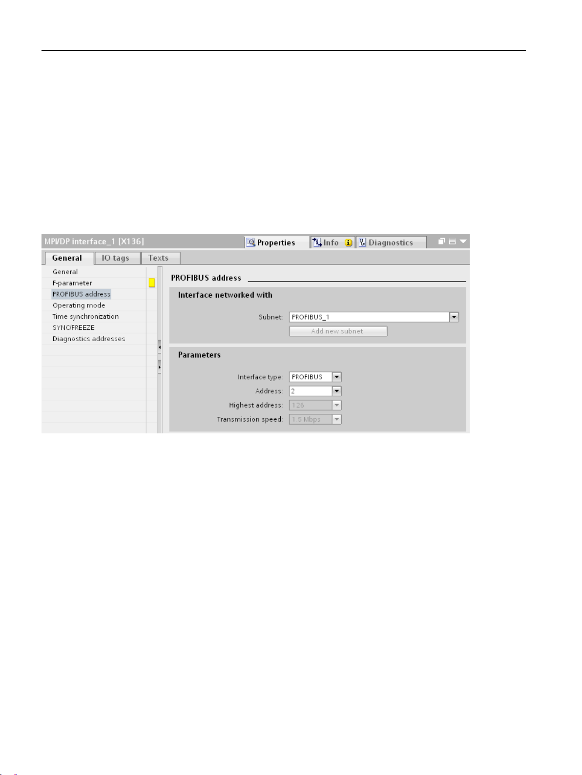
Conguring networks
6.2 Conguring PROFIBUS DP
6.2 Conguring PROFIBUS DP
Procedure
Conguring the PROFIBUS DP address on the PLC
1. In the network view, click the PLC in the basic rack of the NCU.
2. In the "Properties" tab, in the inspector window, select the entry "DP Interface > PROFIBUS
address".
The settings of the PROFIBUS address are displayed.
3. In the Parameters area, set the DP address of the interface on the PLC under "Address". This
is transferred from the conguration to the PLC during the load action.
Conguring the PROFIBUS DP address for the ADI4 module
1. In the network view, click the "DP" interface of the ADI4.
2. In the inspector window "Properties", select the entry "PROFIBUS address".
3. Under "Address" set the DP address that matches the hardware. The congured address must
match the hardware address. It is not accepted automatically.
Information about setting the DP address on the hardware is contained in the "ADI4 - Analog
drive interface for 4 axes" Device Manual.
Checking the transmission speed of the ADI4
Although you can view the "Transmission speed" parameter in the DP interface properties, you
must select the bus system to change it:
1. Click the bus system.
2. In the "Properties" inspector window, check under "Network settings" the "Transmission
speed" entry. The ADI4 module can be operated only with the transmission speed 12 Mbit/s.
SINUMERIK 840D sl STEP 7 Toolbox V17
86 Conguration Manual, 07/2021, 6FC5397-0GP40-0BA2
Page 87

6.3 Conguring Integrated PROFIBUS (DP Integrated)
6.3 Conguring Integrated PROFIBUS (DP Integrated)
Procedure
To check the PROFIBUS addresses, proceed as follows:
1. In the network view, click the DP Integrated interface of the PLC or select the interface in the
device overview.
2. In the "Properties" tab, in the inspector window, select the entry "PROFIBUS address".
Result
The DRIVE-CLiQ sockets of the real hardware are displayed to which the NX modules must be
connected.
Conguring networks
Note
Cycle clock settings
You can only make the cycle clock settings on the PROFIBUS Integrated subnet and not directly
on the interface: For the selected subnet, you nd the cycle clock settings under "Equidistance"
in the inspector window.
Observe the rules for setting the clock cycle at the eld buses (see Commissioning Manual,
"Commissioning CNC: NCK, PLC, drive").
SINUMERIK 840D sl STEP 7 Toolbox V17
Conguration Manual, 07/2021, 6FC5397-0GP40-0BA2 87
Page 88
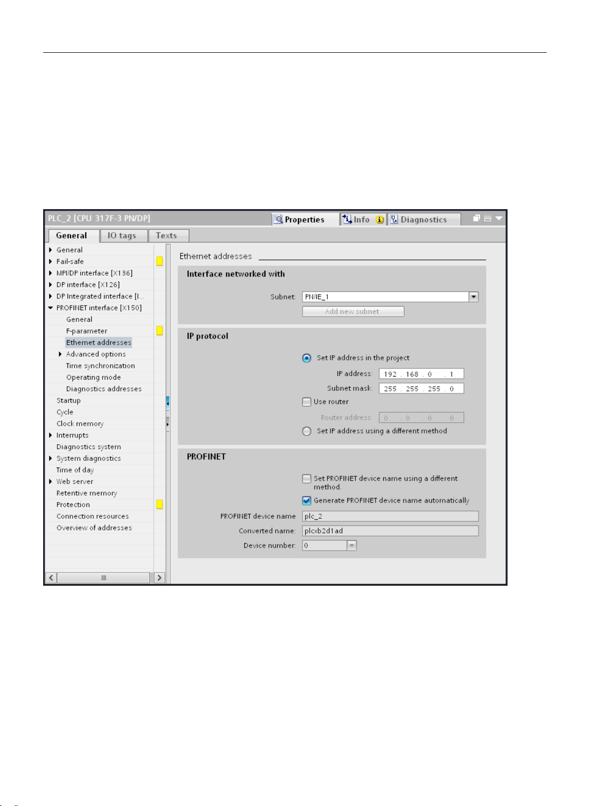
Conguring networks
6.4 Conguring PROFINET
6.4 Conguring PROFINET
Procedure
In order to set the PROFINET interface, proceed as follows:
1. In the network view, click the PLC in the basic rack of the NCU.
2. Under the "Properties" tab in the inspector window, select the "PROFINET interface > Ethernet
addresses" entry.
3. Check under "IP protocol" whether the correct IP address is set ("192.168.0.1" in the example).
SINUMERIK 840D sl STEP 7 Toolbox V17
88 Conguration Manual, 07/2021, 6FC5397-0GP40-0BA2
Page 89

6.5 Conguring PROFINET IO with IRT
6.5.1 Overview
IRT (Isochronous Realtime Ethernet) is a transmission method in which the PROFINET devices are
synchronized very precisely.
The following example conguring sequences serve as an aid for the conguring and provide an
overview of this chapter content.
• Conguring NC-controlled drives isochronously (handling overview) (Page 93)
• Conguring I/O used by NC isochronously (handling overview) (Page 94)
You can, however, make most settings for the clock synchronization in TIA Portal in any order.
You can orient yourself on the following notes:
• Isochronous modules identication in the hardware catalog (Page 91)
• Rules and requirements for clock synchronization (Page 89)
• Match values between PROFINET IO and PROFIBUS Integrated (Page 103)
Conguring networks
6.5 Conguring PROFINET IO with IRT
• General information concerning isochronous mode is also contained in the TIA Portal online
help in Section "Conguring IRT communication".
If, instead, you want to operate drives or I/O isochronously via the PLC, proceed as for a CPU
S7-300. (Use the OB61 as isochronous alarm OB or the TPA1 as process image, and do not enter
the drive or I/O addresses in the machine data.)
6.5.2 Rules and requirements
Irrespective whether you congure isochronous I/O used by NC or isochronous NC-controlled
drives, the value of the TDP send clock must be identical in the complete system (all devices,
modules, submodules and bus systems):
• You can nd these settings in the TIA Portal at the following locations:
– Properties of the PROFINET IO system under "Domain management > Sync domains >
Sync-Domain_x > Send clock".
– Properties of the PROFIBUS Integrated bus system under "Equidistance > DP cycle".
This applies, e.g. even when you connect drives via PROFINET as well as PROFIBUS Integrated.
The default setting of the PROFIBUS DP cycle (send clock) at the integrated PROFIBUS is 2 ms.
During the conguring of drives, the values of the TI and TO times must also be identical in the
complete system:
• Properties of the IO device under "PROFINET interface > Extended options > Isochronous
mode".
• Properties of the bus system (e.g. PROFIBUS Integrated_1) under "Equidistance".
SINUMERIK 840D sl STEP 7 Toolbox V17
Conguration Manual, 07/2021, 6FC5397-0GP40-0BA2 89
Page 90

Conguring networks
6.5 Conguring PROFINET IO with IRT
You can obtain these values automatically from the "NCK" isochronous OB or set them manually.
Note
Restriction on the use of NCU Link
The combination of isochronous PROFINET NC peripherals (drives, inputs/outputs) and NCULink is not supported.
SINUMERIK 840D sl STEP 7 Toolbox V17
90 Conguration Manual, 07/2021, 6FC5397-0GP40-0BA2
Page 91

6.5.3 Isochronous-capable modules identication
Whether a module supports isochronous mode can be determined in the hardware catalog in
the following manner:
• When you select a device in the hardware catalog, you can see from the description in the
"Information" section whether this device supports isochronous mode or IRT.
Conguring networks
6.5 Conguring PROFINET IO with IRT
Figure 6-1 Description of a device in the hardware catalog
• All peripheral modules that have the "HF" name sux can be operated isochronously (e.g. DI
16x 24 VDC HF - 6ES7 521-1BH00).
SINUMERIK 840D sl STEP 7 Toolbox V17
Conguration Manual, 07/2021, 6FC5397-0GP40-0BA2 91
Page 92

Conguring networks
6.5 Conguring PROFINET IO with IRT
Figure 6-2 Hardware catalog - "HF" (High Feature) name sux
• The "Information" section does not explicitly list whether drive telegrams (e.g. SIEMENS
telegram 136) support isochronous mode. The compiler will issue an error message if you
use an isochronous telegram without activating isochronous mode for the associated header
module.
• A listing of isochronous-conform PROFINET controllers and PROFINET devices is contained in
the Service & Support portal:
– Which IO controllers and IO devices support the IRT [...] functions and isochronous
operation? (http://support.automation.siemens.com/WW/view/en/44383954)
– Which SIMATIC S7 components and which drives support isochronous mode? (http://
support.automation.siemens.com/WW/view/en/14747677)
The associated hardware documentation species whether a PROFIBUS controller or device
is isochronous-conform.
SINUMERIK 840D sl STEP 7 Toolbox V17
92 Conguration Manual, 07/2021, 6FC5397-0GP40-0BA2
Page 93

Note
Dierences for devices based on device description les (DDF)
A description of the functionality is also contained in the "Information" section for DDF devices.
The following dierences, however, exist for the conguring:
• GSD devices are not contained in the same folder as standard devices in the hardware
catalog. The SINAMICS S120/S150 CU320-2, for example, are not found under "Field
devices", but rather under "Further eld devices > PROFINET IO > Drives > Siemens AG >
SINAMICS".
• To insert modules or submodules for a GSD device, you must use the device overview rather
than the device view.
6.5.4 Conguring isochronous NC-controlled drives
The procedure for conguring isochronous NC-controlled drives is described below.
If, instead, you want to operate drives isochronously via the PLC, proceed as for a CPU S7-300.
(Use the OB61 as isochronous alarm OB or the TPA1 as process image, and do not enter the drive
addresses in the machine data.)
Conguring networks
6.5 Conguring PROFINET IO with IRT
If, rather than NC-controlled drives, you want to congure I/O used by NC isochronously, proceed
as described in the associated section (Page 94).
Requirement
• The devices to be congured have been inserted (at least one NCU and one PROFINET IO IRT-
conform device).
• The isochronous-conform modules and submodules to be congured have been inserted in
the PROFINET IO IRT-conform device.
See also: Isochronous-capable modules identication (Page 91)
• The PROFINET IO IRT-conform devices are interconnected to the NCU with X150.
Note
Concurrent operation of devices with and without clock synchronization
When you congure devices that do not participate on the IRT communication, observe the rules
for sync domains for PROFINET IO IRT (Page 102).
Procedure overview
Step Description
1 Conguring the NCU (Page 95)
2 Conguring PROFINET IO IRT devices (Page 96)
3 Conguring IO modules or drive telegrams (Page 98)
SINUMERIK 840D sl STEP 7 Toolbox V17
Conguration Manual, 07/2021, 6FC5397-0GP40-0BA2 93
Page 94

Conguring networks
6.5 Conguring PROFINET IO with IRT
Step Description
4 Conguring sync domains (Page 102)
5 Compile the conguration and load into the actual hardware (Page 37)
The compiler issues error messages if you use dierent values for bus cycles. In this case, match the values (Page 103).
6 Assigning drive addresses to the NCU machine data (Page 104)
Note
Reusing congured drives or devices in other projects
You can copy precongured and congured drives or devices with drag-and-drop into a global
library. In this manner, you can insert them later together with the made settings into another
project and so save conguration eort.
Further information on handling libraries in the TIA Portal can be found in the online help under
"Library > Fundamentals".
Further information
Further information on the conguration of IRT can be found in the TIA Portal online help under
"Conguring IRT communication".
6.5.5 Conguring I/O used by NC isochronously
The procedure for conguring isochronous NC I/O is described below.
If, instead, you want to operate I/O isochronously via the PLC, proceed as for a CPU S7-300. (Use
the OB61 as isochronous alarm OB or the TPA1 as process image, and do not enter the I/O
addresses in the machine data.)
If, rather than non-NC I/O, you want to congure NC drives isochronously, proceed as described
in the associated section (Page 93).
Requirement
• The devices to be congured have been inserted (at least one NCU and one PROFINET IO IRT-
conform device).
• The modules to be congured have been inserted in the PROFINET IO IRT-conform device.
See also Isochronous-capable modules identication (Page 91)
• The PROFINET IO IRT-conform devices are interconnected to the NCU with X150.
Note
Concurrent operation of devices with and without clock synchronization
When you congure devices that do not participate on the IRT communication, observe the rules
for sync domains for PROFINET IO IRT (Page 102).
SINUMERIK 840D sl STEP 7 Toolbox V17
94 Conguration Manual, 07/2021, 6FC5397-0GP40-0BA2
Page 95

Procedure overview
Step Description
1 Conguring the NCU (Page 95)
2 Conguring PROFINET IO IRT devices (Page 96)
3 Conguring IO modules or drive telegrams (Page 98)
4 Conguring the input delay for digital input modules (Page 101)
5 Conguring sync domains (Page 102)
6 Compile the conguration and load into the actual hardware (Page 37)
The compiler issues error messages if you use dierent values for bus cycles. In this case, match the values (Page 103).
7 Assigning I/O addresses to the NCU machine data (Page 105)
Note
Reusing congured drives or devices in other projects
You can copy precongured and congured drives or devices with drag-and-drop into a global
library. In this manner, you can insert them later together with the made settings into another
project and so save conguration eort.
Conguring networks
6.5 Conguring PROFINET IO with IRT
Further information for handling libraries in the TIA Portal can be found in the information
system under the keyword "Library > Fundamentals".
Further information
Further information on the conguration of IRT can be found in the information system of the
TIA Portal at "Conguring IRT communication".
6.5.6 Conguring the NCU
When you operate drives or IO isochronously using NC, make the following SINUMERIK-specic
settings.
If, however, you operate the drives or I/O via the PLC, make the settings as for an S7-300-CPU.
(See online help, keyword "Isochronous mode, congure".)
Requirement
• The devices to be congured have been inserted (at least one NCU and one PROFINET IO IRT-
conformant device).
• The isochronous-conform modules and submodules to be congured have been inserted in
the PROFINET IO IRT-conformant device.
See also: Isochronous-capable modules identication (Page 91)
• The PROFINET IO IRT-conformant devices are interconnected to the NCU with X150.
SINUMERIK 840D sl STEP 7 Toolbox V17
Conguration Manual, 07/2021, 6FC5397-0GP40-0BA2 95
Page 96

Conguring networks
6.5 Conguring PROFINET IO with IRT
Note
Concurrent operation of devices with and without clock synchronization
When you congure devices that do not participate on the IRT communication, observe the rules
for sync domains for PROFINET IO IRT (Page 102).
Procedure
To congure the NC of the NCU to use isochronous mode, proceed as follows:
1. Select the PLC of the NCU.
2. In the "Properties > General" inspector window, select the "Alarms > Isochronous alarms >
NCK" item.
3. In the "Distributed I/O" dropdown list, select the PROFINET IO system with which you have
interconnected the PROFINET IO IRT devices (e.g. "PROFINET IO system (100)").
Note
Changing the name and number of the PROFINET IO system
You can specify the name and number of the PROFINET IO system in the settings of the IO
system (bus system on X150). You nd the setting under "General" provided IO system is
highlighted in the network view.
If, however, the sync domain or nothing is highlighted, the setting is not available.
To highlight the IO system, position the mouse cursor over the IO system in the network view
and activate the appropriate option box in the displayed tooltip.
4. In the "Application cycle (ms)" dropdown list, select the value that you dened as send clock
of the sync domain and the DP cycle of SINAMICS Integrated, e.g. 2000.
5. Enter "2" in the "PIP" (process image partition) text eld. The setting must match the "process
image" setting on the IO modules.
6.5.7 Conguring PROFINET IO IRT devices
Requirement
• The devices to be congured have been inserted (at least one NCU and one PROFINET IO IRT-
conform device).
• The isochronous-conform modules and submodules to be congured have been inserted in
the PROFINET IO IRT-conform device.
See also Isochronous-capable modules identication (Page 91)
• The PROFINET IO IRT-conform devices are interconnected to the NCU with X150.
• The NCU is congured.
See also Conguring the NCU (Page 95)
SINUMERIK 840D sl STEP 7 Toolbox V17
96 Conguration Manual, 07/2021, 6FC5397-0GP40-0BA2
Page 97
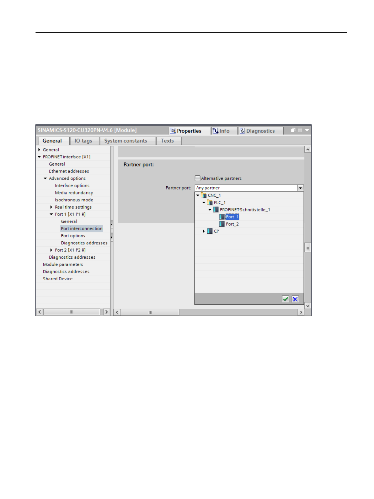
Procedure
Conguring networks
6.5 Conguring PROFINET IO with IRT
To congure devices for isochronous operation, proceed as follows:
1. Switch to the device view of the PROFINET IO IRT device and select it.
2. Select in the "Properties > General" inspector window under "PROFINET interface > Extended
options" the port (e.g. Port [X1 P1]).
3. Select a specic port on the PLC in the "Partner port" dropdown list in the "Port
interconnection" section: "Port_1" (X150 P1) or "Port_2" (X150 P2).
Figure 6-3 Example port interconnection
The selected port of the device is interconnected with the appropriate port of the PLC.
(Alternatively, you can make the port interconnection between devices graphically in the
topology view.)
4. In the "Cable length" dropdown list, enter the length of the actual cable in order to minimize
the signal run time.
5. Switch in the sector tree of the inspector window to the "PROFINET interface > Extended
options > Isochronous mode" entry.
6. Activate the "Isochronous operation" checkbox.
The isochronous operation of the device is activated and concurrently the synchronization
role of the device set to "sync slave" and the RT class set to "IRT" in the sync domain.
SINUMERIK 840D sl STEP 7 Toolbox V17
Conguration Manual, 07/2021, 6FC5397-0GP40-0BA2 97
Page 98

Conguring networks
6.5 Conguring PROFINET IO with IRT
7. In the "Ti/To values" dropdown list, select "From the OB".
This causes the value to be taken automatically from the setting of the isochronous alarm OB
"NCK".
8. Activate the isochronous mode individually for the desired modules of the device in the
"Detail overview" table.
Figure 6-4 Settings for the isochronous mode using the example of a SINAMICS S120/S150 CU320-2
6.5.8 Conguring IO modules or drive telegrams
The isochronous-conform modules (e.g. input/output modules, DO or telegrams) to be
congured must be selected individually in order to make the desired settings in the "Properties"
inspector window. You can select these modules in the device view or device overview (in the
case of GSD-based devices, only in the device overview).
Requirement
• The devices to be congured have been inserted (at least one NCU and one PROFINET IO IRT-
conform device).
• The isochronous-conform modules and submodules to be congured have been inserted in
the PROFINET IO IRT-conform device.
See also Isochronous-capable modules identication (Page 91)
• The PROFINET IO IRT-conform devices are interconnected to the NCU with X150.
• The NCU is congured.
See also Conguring the NCU (Page 95)
• The device or the rack is congured.
See also Conguring PROFINET IO IRT devices (Page 96)
SINUMERIK 840D sl STEP 7 Toolbox V17
98 Conguration Manual, 07/2021, 6FC5397-0GP40-0BA2
Page 99

Procedure
Conguring networks
6.5 Conguring PROFINET IO with IRT
To congure the inserted IO modules, select them successively and make the settings
individually for each module in the inspector window. Proceed as follows:
1. In the device view, select the rack and open the device overview.
Figure 6-5 Device overview example of a GSD drive device with modules
2. In the device overview, select on the rack of the PROFINET unit one of the inserted modules
to be congured.
SINUMERIK 840D sl STEP 7 Toolbox V17
Conguration Manual, 07/2021, 6FC5397-0GP40-0BA2 99
Page 100

Conguring networks
6.5 Conguring PROFINET IO with IRT
3. In the "Properties > General" inspector window, select the "I/O addresses" entry.
Figure 6-6 Settings for I/O addresses
SINUMERIK 840D sl STEP 7 Toolbox V17
100 Conguration Manual, 07/2021, 6FC5397-0GP40-0BA2
 Loading...