


Siemens NXPLUS C Installation And Operating Instructions Manual
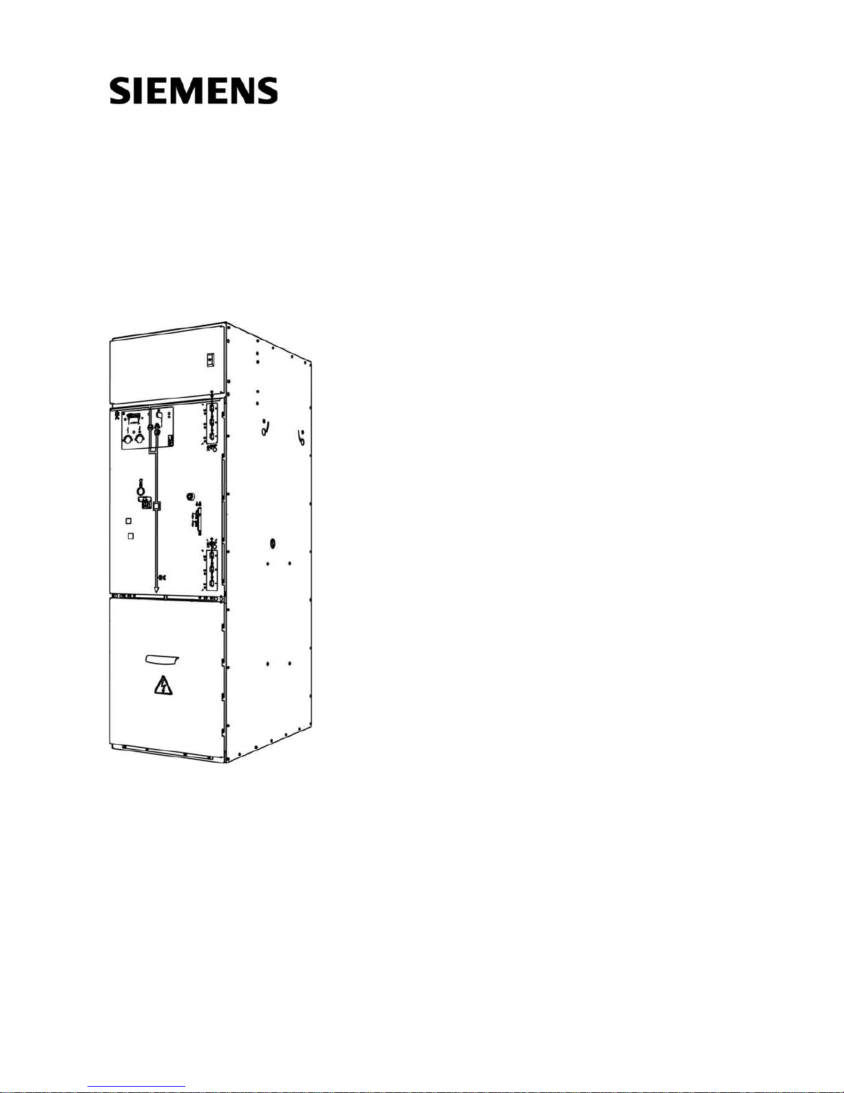
Medium-Voltage Switchgear
Type NXPLUS C Wind Fixed-Mounted Circuit-Breaker Switchgear up to 36 kV,
Extendable
Single Busbar, Metal-Enclosed, Gas-Insulated
Medium-Voltage
Switchgear
INSTALLATION AND
OPERATING
INSTRUCTIONS
Order No.: 802-9074.9
Revision: 05
Issue: 06-02-2014
2/172 Revision 05 • INSTALLATION AND OPERATING INSTRUCTIONS • NXPLUS C Wind • 802-9074.9
About these Instructions
These instructions do not purport to cover all details or
variations in equipment, nor to provide for every possible
contingency to be met in connection with installation or
operation.
For details about technical design and equipment like e.g.
technical data, secondary equipment, circuit diagrams,
please refer to the order documents.
The switchgear is subject to continuous technical
development within the scope of technical progress. If not
stated otherwise on the individual pages of these
instructions, we reserve the right to modify the specified
values and drawings. All dimensions are given in mm.
Should further information be desired or should particular
problems arise which are not covered sufficiently by these
instructions, the matter should be referred to the
competent Siemens department.
The contents of this instruction manual shall not become
part or modify any prior or existing agreement,
commitment or relationship. The Sales Contract contains
the entire obligations of Siemens. The warranty contained
in the contract between the parties is the sole warranty of
Siemens. Any statements contained herein do not create
new warranties or modify the existing warranty.

802-9074.9 • INSTALLATION AND OPERATING INSTRUCTIONS • NXPLUS C Wind • Revision 05 3/172
Contents
Safety instructions .............................................5
1 Signal terms and definitions ...............................5
2 General instructions ...........................................6
3 Due application .................................................. 7
4 Qualified personnel ............................................7
Description ......................................................... 8
5 Features............................................................. 8
6 Panel types....................................................... 10
7 Examples for panel versions ............................. 11
8 Components .................................................... 13
8.1 Circuit-breaker ................................................. 13
8.2 Three-position disconnector .............................15
8.3 Operating mechanisms for the three-position
disconnector ....................................................16
8.4 Three-position switch-disconnector ..................17
8.5 Operating mechanisms of three-position
switch-disconnectors........................................ 18
8.6 Voltage transformers........................................ 19
8.7 Current transformers........................................ 20
8.8 Busbar system.................................................. 21
8.9 Cable connection .............................................22
8.10 Ready-for-service indicator ...............................25
8.11 Interlocks ......................................................... 26
8.12 Voltage detecting systems................................ 27
8.13 Short-circuit/earth-fault indicator
(ring-main panel) .............................................31
8.14 Accessories ......................................................32
9 Technical data.................................................. 36
9.1 Complete switchgear........................................ 36
9.2 Classification of NXPLUS C Wind according to
IEC 62 271-200 ................................................38
9.3 Standards, specifications, guidelines................. 39
9.4 Rating plates ....................................................40
9.5 Vacuum circuit-breaker..................................... 41
9.6 Three-position disconnector for circuit-breaker
panels and disconnector panels 630 A / 800 A /
1000 A............................................................. 44
9.7 Three-position switch-disconnector ..................44
9.8 Endurance classes ............................................44
10 End of service life ............................................. 46
Installation ....................................................... 47
11 Constructional stipulations ...............................47
11.1 Switchgear room.............................................. 47
11.2 Constructional data of the foundation .............. 48
11.3 Transport units................................................. 57
12 Before installation ............................................59
12.1 Preliminary clarifications................................... 59
12.2 Intermediate storage ........................................59
12.3 Tools/auxiliary means .......................................60
12.4 Installation and fixing material ......................... 60
12.5 Comments on electromagnetic compatibility ....61
13 Unloading and erecting the switchgear............. 62
13.1 Packing and transport unit................................ 62
13.2 Completeness and transport damages ..............62
13.3 Unloading transport units................................. 63
13.4 Transport to the place of installation
(switchgear room)............................................ 63
13.5 Checking the ready-for-service indicator ...........67
14 Assembling the switchgear............................... 69
14.1 Bolting panels together ....................................69
14.2 Fastening the switchgear to the foundation...... 72
14.3 Assembling the busbars.................................... 72
14.4 Installing busbar voltage transformers .............. 80
14.5 Installing the earthing busbar ........................... 88
14.6 Switchgear earthing .........................................89
14.7 Installing low-voltage compartments................ 90
14.8 Busbar covers................................................... 90
14.9 Installing the switchgear termination................ 91
14.10 Extension with individual panels....................... 91
15 Electrical connections....................................... 93
15.1 Installation work at the pressure-resistant floor
cover ............................................................... 93
15.2 Connecting cable T-plugs ................................. 99
15.3 Cable connection with cable-type current
transformers ..................................................105
15.4 Connecting surge arresters............................. 108
15.5 Connecting auxiliary circuits ........................... 109
16 Installation of designs with degree of
protection IP31D
(low-voltage compartment)............................ 114
16.1 IP31D - protection against vertically
falling water drops .........................................114
17 Commissioning ..............................................118
17.1 Final work ...................................................... 118
17.2 Checking the accessories ................................ 120
17.3 Instructing operating personnel...................... 120
17.4 Function test / Test operation ......................... 120

4/172 Revision 05 • INSTALLATION AND OPERATING INSTRUCTIONS • NXPLUS C Wind • 802-9074.9
17.5 Performing the power- frequency
voltage test.................................................... 126
17.6 Primary injection test ..................................... 127
17.7 Applying operating voltage (high voltage)...... 127
Operation........................................................129
18 Indicators and control elements ..................... 129
19 Checking the ready-for-service indicator......... 132
20 Operating the circuit-breaker ......................... 133
20.1 Closing the circuit-breaker.............................. 133
20.2 Opening the circuit-breaker............................ 133
20.3 Test operation................................................ 133
20.4 Test operation with auxiliary voltage
(motor operating mechanism) ....................... 134
20.5 Charging the closing spring manually
with the hand crank....................................... 135
21 Operating the three-position disconnector ..... 136
21.1 Operating levers for three-position
disconnector.................................................. 136
21.2 Closing the three-position disconnector ......... 137
21.3 Opening the three-position disconnector........ 137
21.4 Earthing/ready-to-earth with the
three-position switch ..................................... 138
21.5 De-earthing with the three-position switch..... 138
21.6 Operating the three-position disconnector
with motor operating mechanism .................. 139
21.7 Emergency operation of the three-position
disconnector.................................................. 139
22 Operating the three-position
switch-disconnector....................................... 145
22.1 Operating lever for three-position
switch-disconnector (with adapter) ................ 145
22.2 Closing the three-position
switch-disconnector....................................... 145
22.3 Opening the three-position
switch-disconnector....................................... 146
22.4 Earthing the three-position
switch-disconnector....................................... 147
22.5 De-earthing with three-position
disconnector.................................................. 148
22.6 Operating three-position switch-disconnector
with motor operating mechanism .................. 149
23 Work-in-progress earthing.............................. 150
24 Verification of safe isolation from supply ........ 152
24.1 LRM plug-in sockets ....................................... 152
24.2 Indications VOIS, VOIS R+,
CAPDIS -S1+/-S2+........................................... 153
24.3 Indications WEGA 1.2, WEGA 2.2.................... 155
25 Short instructions .......................................... 156
25.1 Operating circuit-breaker panels..................... 157
25.2 Operating disconnector panels....................... 160
26 Cable testing.................................................. 166
27 Service instructions........................................ 168
27.1 Maintenance.................................................. 168
27.2 Switchgear extension and replacement of
panels and components ................................. 168
Index ...............................................................169
802-9074.9 • INSTALLATION AND OPERATING INSTRUCTIONS • NXPLUS C Wind • Revision 05 5/172
Safety instructions
Safety instructions
1 Signal terms and definitions
Symbols used Operation symbol: Identifies an operation. Asks the operator to perform an operation.
r Result symbol: Identifies the result of an operation.
DANGER!
as used in these instructions, this means that personal injuries can occur if the relevant
precautionary measures are not taken.
Observe the safety instructions.
ATTENTION!
as used in these instructions, this means that damage to property or environment can occur if
the relevant precautionary measures are not taken.
Observe the safety instructions.
NOTE!
as used in these instructions, this points at facilitations of work, particularities for operation or
possible maloperation.
Observe the notes.
Safety instructions
6/172 Revision 05 • INSTALLATION AND OPERATING INSTRUCTIONS • NXPLUS C Wind • 802-9074.9
2 General instructions
Independently of the safety instructions given in these operating instructions, the local laws,
ordinances, guidelines and standards for operation of electrical equipment as well as for labor,
health and environmental protection apply.
Five Safety Rules of
Electrical Engineering
The Five Safety Rules of Electrical Engineering must be complied with during operation of the
products and components described in these operating instructions:
• Isolate.
• Secure against reclosing.
• Verify safe isolation from supply.
• Earth and short-circuit.
• Cover or barrier adjacent live parts.
Hazardous materials If hazardous materials are required to perform the work, the relevant safety data sheets and
operating instructions must be observed.
Personal protective
equipment (PPE)
For switchgear with proven internal arc classification according to IEC 62271 Part 200, no
protective equipment is required for operating the switchgear.
To work on switchgear where covers have to be removed, personal protective equipment
has to be worn for protection against hot gases exhausting in case of internal arc.
To select the protective equipment, the national standards and specifications of the
corresponding authorities and professional associations must absolutely be observed.
The protective equipment consists of:
• Protective clothing
•Safety shoes
•Gloves
• Helmet and face protection
DANGER!
Any kind of modification on the product or alteration of the product must be coordinated with
the manufacturer in advance. Uncoordinated modifications or alterations can cause the
expiration of warranty claims, cause danger to life, limb and other legally protected interests.
The fulfillment of the type tests (according to IEC 62271-200) may not be guaranteed
anymore. This applies especially though not exclusively to the following actions, e.g. in the
course of maintenance or repairs:
Original Siemens spare parts were not used.
Service engineers performing replacement were not trained and certified by Siemens.
Parts were fitted or adjusted incorrectly.
Settings were not made in accordance with Siemens specifications.
After installation and setting, no final check was performed by a service engineer approved
by Siemens, including documentation of the test results.
Maintenance was not done according to the operating instructions of the Siemens
products.
802-9074.9 • INSTALLATION AND OPERATING INSTRUCTIONS • NXPLUS C Wind • Revision 05 7/172
Safety instructions
3 Due application
The switchgear corresponds to the relevant laws, prescriptions and standards applicable at the
time of delivery. If correctly used, they provide a high degree of safety by means of logical
mechanical interlocks and shockproof metal enclosure of live parts.
4 Qualified personnel
Qualified personnel in accordance with these instructions are persons who have been instructed
by the Switchgear Factory Frankfurt (participation in an assembly and installation training with
certificate), who are familiar with transport, installation, commissioning, maintenance and
operation of the product, and who have appropriate qualifications for their work.
• Training and instruction or authorization to switch on, switch off, earth and identify power
circuits and equipment / systems as per the relevant safety standards.
• Training regarding the applicable specifications for the prevention of accidents and the use
of appropriate safety equipment.
• Training in first aid and behavior in the event of possible accidents.
DANGER!
The perfect and safe operation of this switchgear is conditional on:
Observance of operating and installation instructions.
Qualified personnel.
Proper transportation and correct storage of the switchgear.
Correct installation and commissioning.
Diligent operation and maintenance.
Observance of the instructions applicable at site for installation, operation and safety.

Description
8/172 Revision 05 • INSTALLATION AND OPERATING INSTRUCTIONS • NXPLUS C Wind • 802-9074.9
Description
5 Features
Typical uses Extendable fixed-mounted circuit-breaker switchgear NXPLUS C Wind, single busbar, is used,
above all, in wind turbines.
The panels are designed for rated voltages up to 36 kV, rated currents up to 1000 A, and a
rated short-time withstand current of 25 kA as a maximum.
Insulating gas SF
6
Sulfur hexafluoride SF6 is used as insulating gas. SF6 insulates live parts between each other
and against the earthed vessel wall. For panels with switch disconnector, SF
6
serves also for
extinguishing the internal arc.
The switchgear is delivered ex works with SF
6
filling, ready for service. The SF6 filling is
provided to last the total service life of the switchgear.
No gas work is required for installation on site and later extensions.
Filling quantity as per rating plate.
Technology • Factory-assembled, type-tested and metal-enclosed switchgear for indoor installation
• Stainless-steel vessel welded gas-tight
• Switchgear vessel, gas-insulated
• Single-pole insulated: cable connection and busbar
• Installation and extension without SF
6
gas work
• Screened busbar system, insulated with silicone rubber
• Three-position switch-disconnector with load-break and make-proof earthing function
• Cable connection from front with cable plugs
• Maintenance-free
Personal safety • Safe-to-touch due to metal enclosure of live parts
• Clear mimic diagram with mechanical position indicators
• Logical mechanical interlocking
• Capacitive voltage detecting system to verify safe isolation from supply
• Earthing of feeders by means of the earthing function of the three-position disconnector in
the disconnector panel, earthing of feeders by means of the earthing fuction of the threeposition disconnector in the ring-main panel and make-proof earthing through the threeposition disconnector and the circuit-breaker in the circuit-breaker panel
• Resistance to internal arcing
Security of operation and
availability
• Hermetically sealed primary enclosure independent of environmental effects such as
pollution, humidity and small animals
• Welded switchgear vessel, sealed for life
• Operating mechanisms of switching devices accessible outside the switchgear vessel
• Maloperation is practically excluded due to interlocks and logical arrangement of operating
elements.
• Ready-for-service indicator self-monitoring, easy to read, independent of temperature and
environmental pressure variations, with contactless measured-value acquisition and with
signaling contacts (option) 1NO + 1NC for telecommunication
• Minimum fire load
• Switchgear vessel designed as "sealed pressure system" according to IEC 62 271-200, i.e.
the insulating gas filling requires no maintenance

802-9074.9 • INSTALLATION AND OPERATING INSTRUCTIONS • NXPLUS C Wind • Revision 05 9/172
Description
Cost-efficiency Extremely low "life-cycle costs" and maximum availability thanks to:
• Maintenance-free design (for the service life)
• Climatic independence
• Minimum space requirements
• Long service life
Seismic withstand
capability (option)
NXPLUS C Wind switchgear can be upgraded for regions at risk from earthquakes. For
upgrading, earthquake qualification testing has been carried out in accordance with the
following standards:
• IEC 60068-3-3 “Guidance – seismic test methods for equipment”
• IEC 60068-2-57 “Test Ff: Vibration – Time-history method”
• IEC 60068-2-59 “Test Fe: Vibration – Sine-beat method”
• IEEE 693-2005 “Recommended Practice for Seismic Design of Substations”.
For installation on even and rigid concrete or steel structure (without considering building
influences), the tested ground accelerations meet the following requirements:
• Uniform Building Code 1997 (UBC) – Zone 4
• California Building Code 1998 (CBC) – Zone 4
• IEEE 693-2005 – High required response spectrum.
Description
10/172 Revision 05 • INSTALLATION AND OPERATING INSTRUCTIONS • NXPLUS C Wind • 802-9074.9
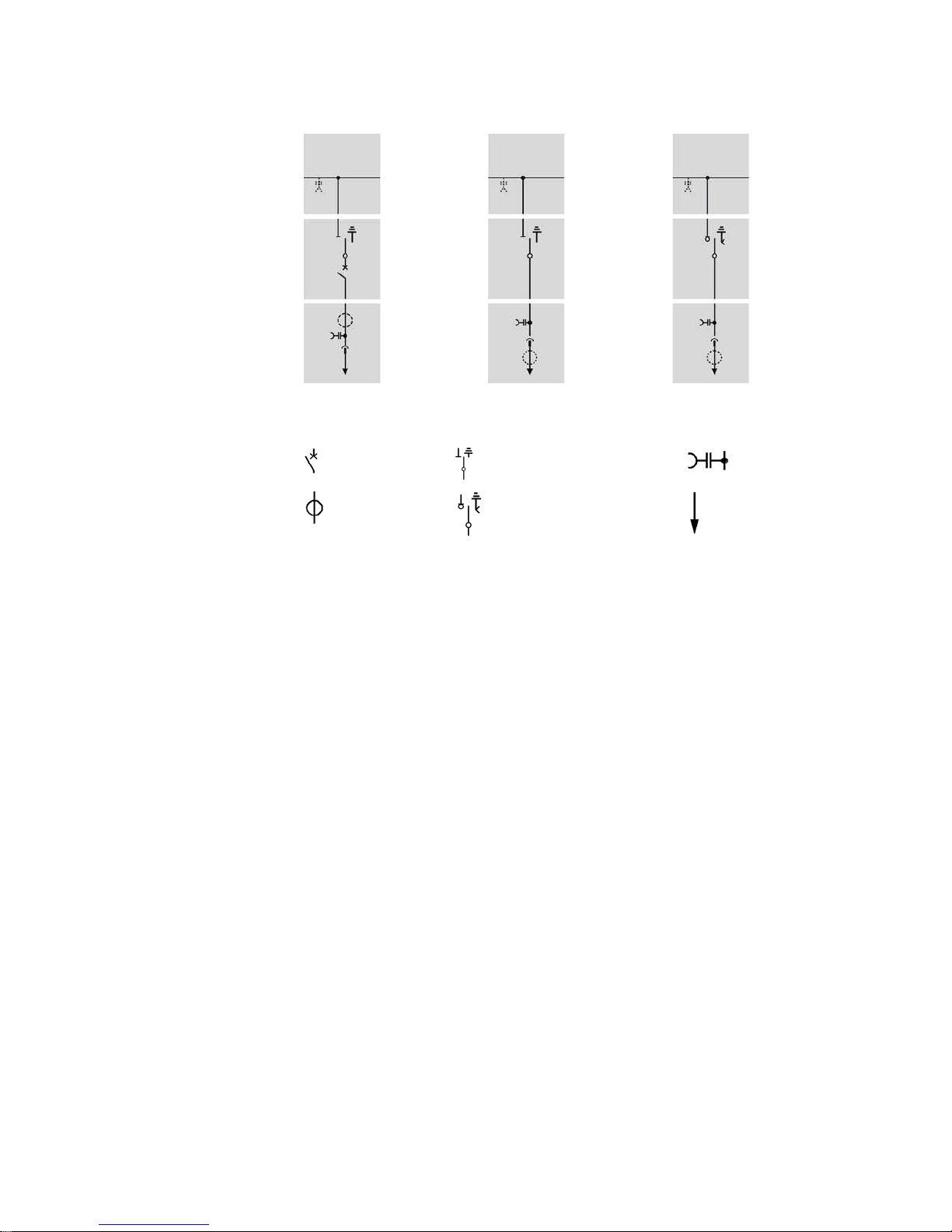
6 Panel types
Circuit-breaker panel Disconnector panel Ring-main panel
Vacuum circuitbreaker
Three-position disconnector
Capacitive voltage
detecting system
Current
transformer
Three-position switchdisconnector
Cable (not included in the
scope of supply)
------ These
components can
be connected
partially or
optionally
802-9074.9 • INSTALLATION AND OPERATING INSTRUCTIONS • NXPLUS C Wind • Revision 05 11/172
Description
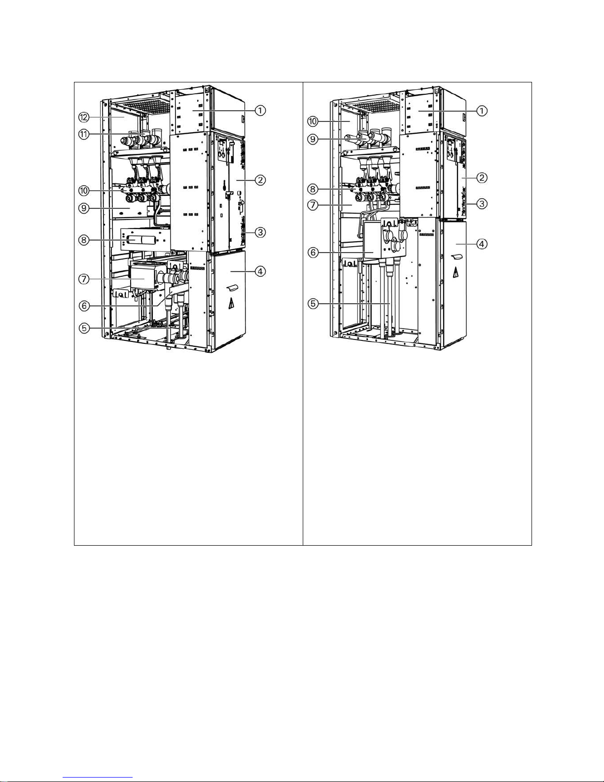
7 Examples for panel versions
Fig. 1: Circuit-breaker panel (630 A)
Fig. 2: Disconnector panel (630 A / 1000 A)
Low-voltage compartment
Low-voltage compartment
Operating front
Operating front
Capacitive voltage detecting system (busbar: top-right, cable
feeder: bottom-right)
Capacitive voltage detecting system (busbar: top-right, cable
feeder: bottom-right)
Cable compartment cover
Cable compartment cover
Cable with cable plug for outside-cone plug-in system
Cable with cable plug for outside-cone plug-in system
Arcing plate
Arcing plate
Ring-core current transformer (option)
Switchgear vessel, hermetically welded, filled with SF6 gas, with
bursting disc
Circuit-breaker with vacuum interrupters
Switchgear vessel, hermetically welded, filled with SF6 gas, with
bursting disc
Three-position disconnector
Busbar system
Three-position disconnector
Pressure relief duct
Busbar system
Pressure relief duct
Description
12/172 Revision 05 • INSTALLATION AND OPERATING INSTRUCTIONS • NXPLUS C Wind • 802-9074.9
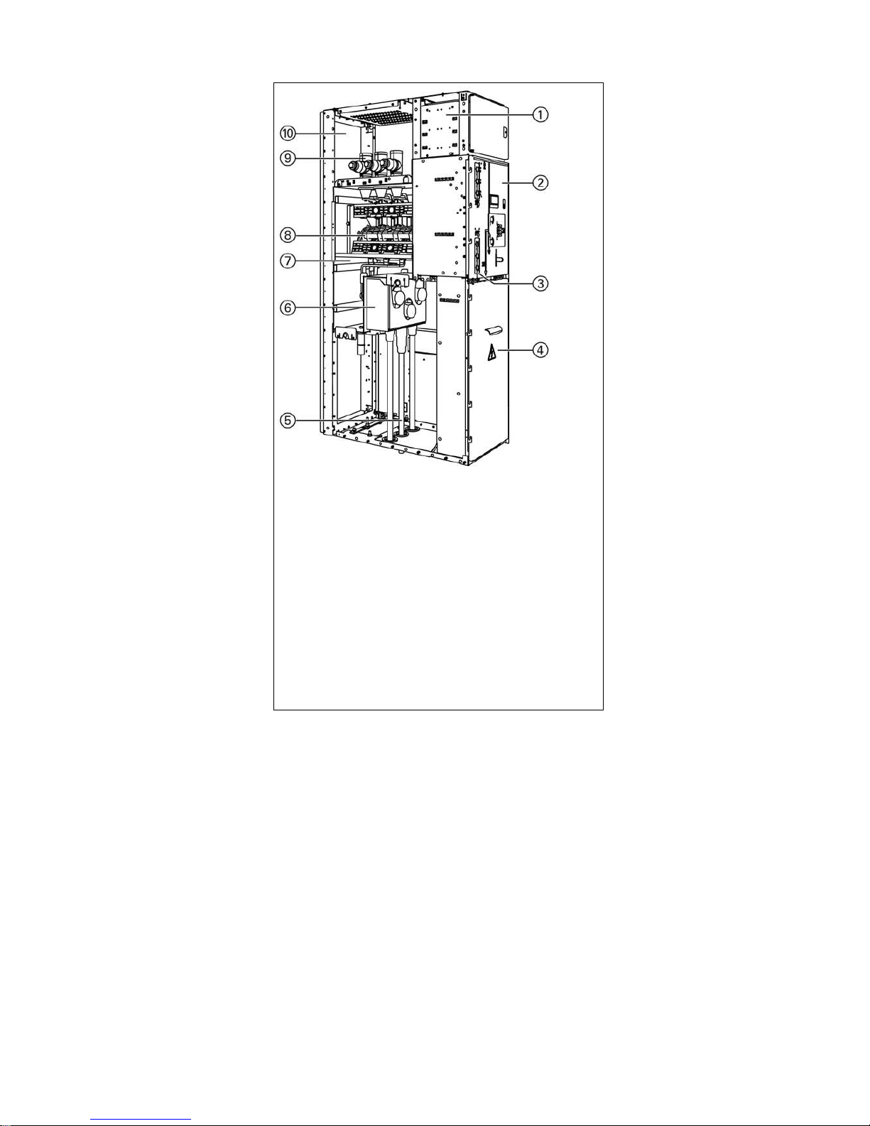
Fig. 3: Ring-main panel (630 A)
Low-voltage compartment
Operating front
Capacitive voltage detecting system (busbar: top-right, cable
feeder: bottom-right)
Cable compartment cover
Cable with cable plug for outside-cone plug-in system
Arcing plate
Switchgear vessel, hermetically welded, filled with SF6 gas, with
bursting disc
Three-position switch-disconnector
Busbar system
Pressure relief duct
802-9074.9 • INSTALLATION AND OPERATING INSTRUCTIONS • NXPLUS C Wind • Revision 05 13/172
Description
8 Components
8.1 Circuit-breaker
Design The Siemens vacuum circuit-breaker (VCB) 3AH55 is a three-pole indoor circuit-breaker for a
rated voltage of 36 kV.
The circuit-breaker consists of the following components:
• Operating mechanism with stored-energy spring mechanism and control elements
• Three circuit-breaker poles with vacuum interrupters
• Partition plate
• Operating rods for contact operation, mounted in the vessel front (partition plate) in a
movable way and without seals by means of welded-in metal bellows.
The operating mechanism box accommodates all electrical and mechanical components
required for closing and opening the circuit-breaker.
3AH55 circuit-breakers need no opening spring, as the energy for opening is stored in the
contact pressure springs during the closing process.
The operating mechanism box is closed with a removable cover. The cover contains openings
for the control elements and indicators.
Circuit-breakers with motor operating stored-energy mechanism are closed with the ON
pushbutton. In case of manual operating spring mechanism, the circuit-breaker is
automatically closed after the closing spring is charged. The movement transmission to the
circuit-breaker poles is performed by metal bellows. In the case of a motor operating storedenergy mechanism, the closing spring is charged again immediately after a closing.
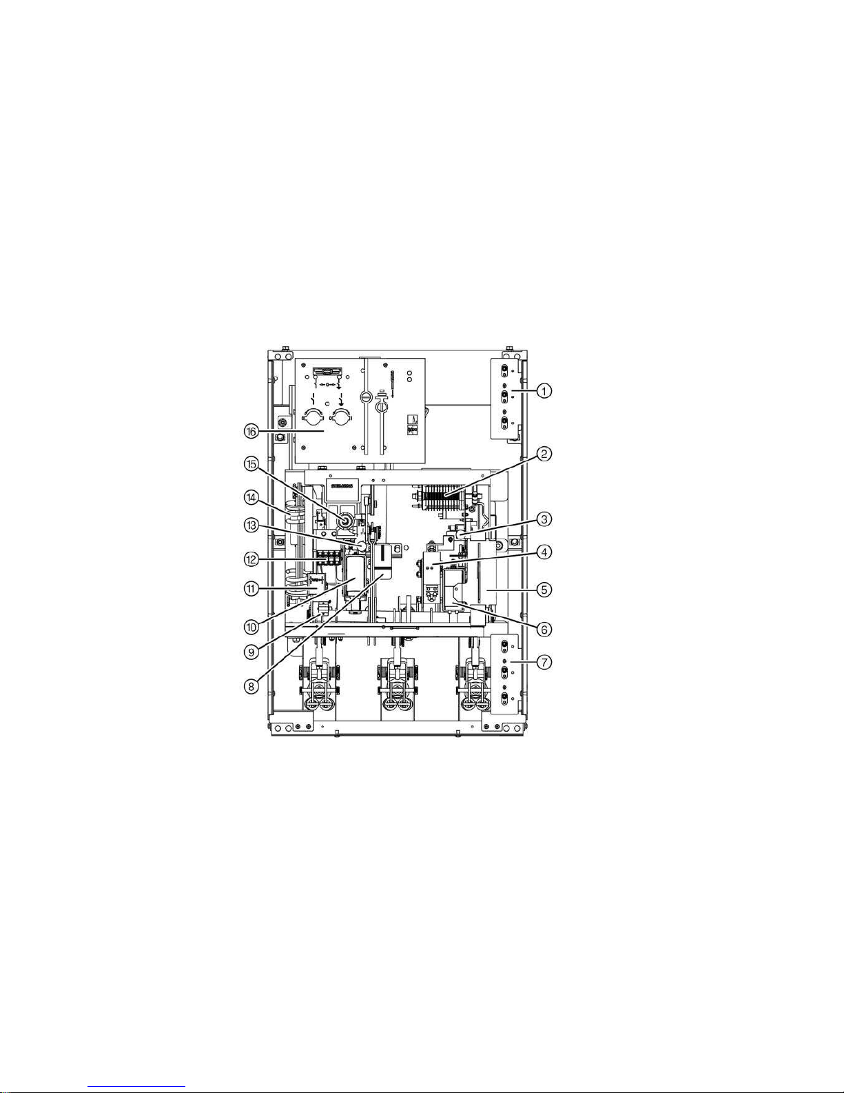
Fig. 4: Circuit-breaker operating mechanism, shown with
stored-energy spring mechanism
Capacitive voltage detecting
system at the busbar (option)
Auxiliary switch (S1)
Operation for OFF
pushbutton
Additional release (option)
"Feeder earthed“ locking
device
Shunt release (Y1)
Capacitive voltage detecting
system at the cable feeder
Position indicator for circuitbreaker
Operations counter
Closing solenoid (Y9)
"Spring charged/spring not
charged" indicator
Position switch (S4)
Operation for ON pushbutton
Closing spring
Gear with motor (M1)
Control board for threeposition-disconnector
Description
14/172 Revision 05 • INSTALLATION AND OPERATING INSTRUCTIONS • NXPLUS C Wind • 802-9074.9
If the motor supply voltage fails, the closing spring can be charged manually. To do this, there
is an opening in the cover with the hand crank coupling of the gear behind. The charging
condition of the spring can be read on the indicator.
The operations counter shows the number of closing processes.
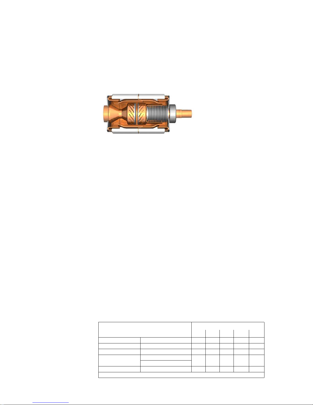
Vacuum interrupters The vacuum interrupter is fixed at the interrupter support. The fixed contact is directly
connected to the housing. The moving contact is firmly connected to the connection bolt and
is centrally aligned in the guide. A metal bellows forms the vacuum-tight connection to the
interrupter housing.
Fig. 5: Vacuum interrupter
Equipment The basic version of the vacuum circuit-breaker with manual spring-operated mechanism is
equipped as follows:
• Operating mechanism
• Shunt release (Y1)
• Low-voltage plug connector with 10-pole wiring (Q0)
• Auxiliary switch 4NO + 4NC or 3NO + 4NC freely available (S1)
• Circuit-breaker tripping signal, cutout switches (S6, S7)
•Operations counter
• Feeder locking device
Additional equipment • Motor operating mechanism (M1) with mechanical and electrical anti-pumping device
• Position switch for "closing spring charged" indication (S41, S42)
• Closing solenoid (Y9) (option)
• 2nd shunt release (Y2)
• Undervoltage release (Y7)
• C.t.-operated release (Y4)
• Low-energy c.t.-operated release (Y6)
• Interlocking between feeder locking device and three-position disconnector (circuit-breaker
only lockable in earthed position)
• Interlocking between feeder locking device, three-position disconnector and cable
compartment cover (circuit-breaker only lockable in earthed position, cable compartment
cover only removable in earthed position)
• Interlocking between feeder locking device, three-position disconnector and cable
compartment cover (circuit-breaker only lockable in earthed position, cable compartment
cover only removable in earthed position) and additional key-operated interlock
Possible release
combinations
Release Release combination
123 4 5
1st shunt release Type 3AY1510 X X X X X
2st shunt release Type 3AX1101 – X – – X
3st shunt release Type 3AX1101 – – – – –
C.t.-operated release Type 3AX1102; 0.5 A or – – X – X
Type 3AX1104, 0.1 Ws
Undervoltage release Type 3AX1103 – – – X –
X: 1 unit of each release, a maximum of 3 releases can be combined
802-9074.9 • INSTALLATION AND OPERATING INSTRUCTIONS • NXPLUS C Wind • Revision 05 15/172
Description
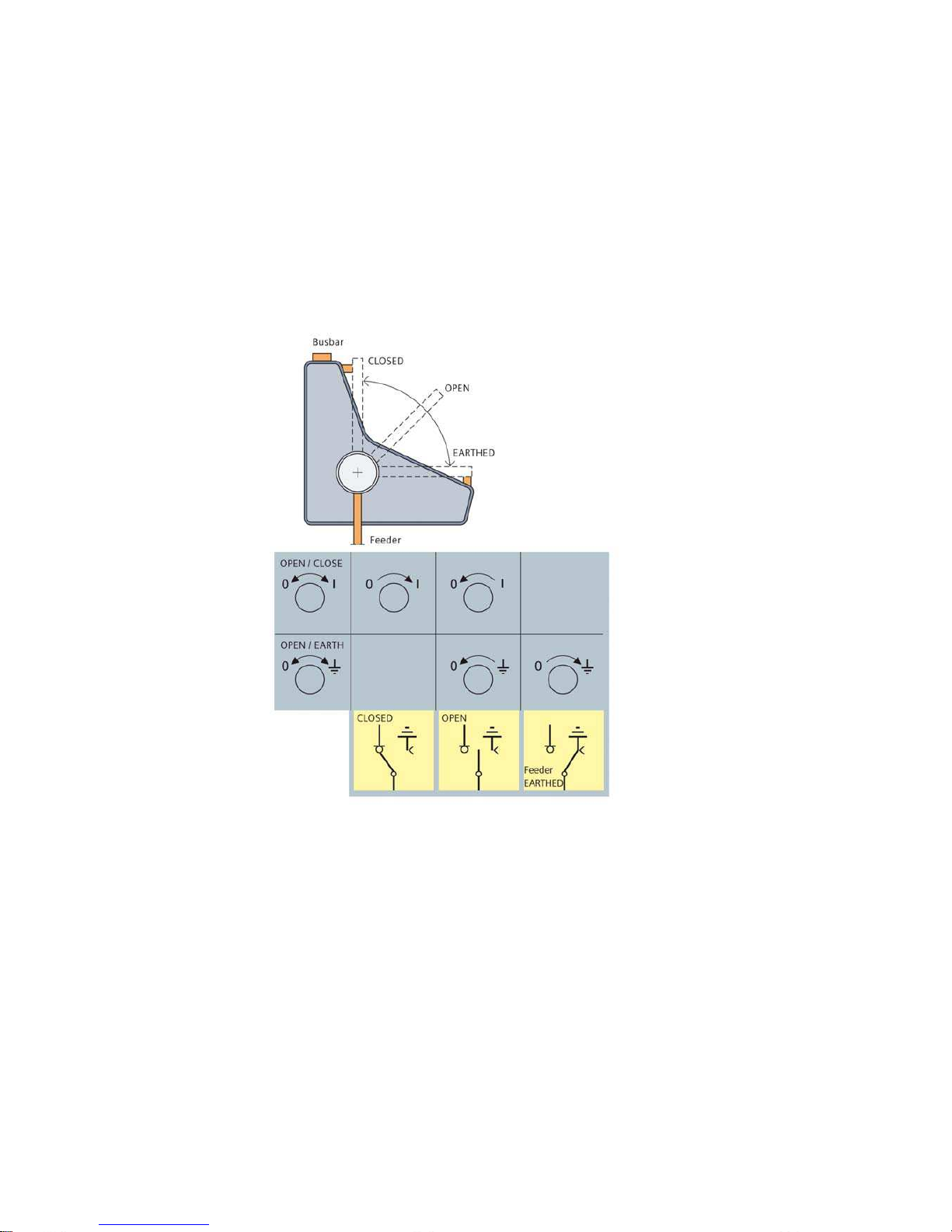
8.2 Three-position disconnector
The three-position disconnector combines the functions:
• DISCONNECTING
•EARTHING
• READY-TO-EARTH
Application:
• Circuit-breaker panel 630 A and 1000 A
• Disconnector panel 630 A and 1000 A
Features • Operation via rotary bushings welded into the front of the switchgear vessel
Equipment The basic version of the three-position disconnector is equipped as follows:
• Auxiliary switch, freely available
- in EARTHING function with 3NO + 3NC
- in DISCONNECTING function with 3NO + 3NC
• In the circuit-breaker panel: Mechanical interlocking to the circuit-breaker
Additional equipment • Motor operating mechanism
• Electromechanical interlock
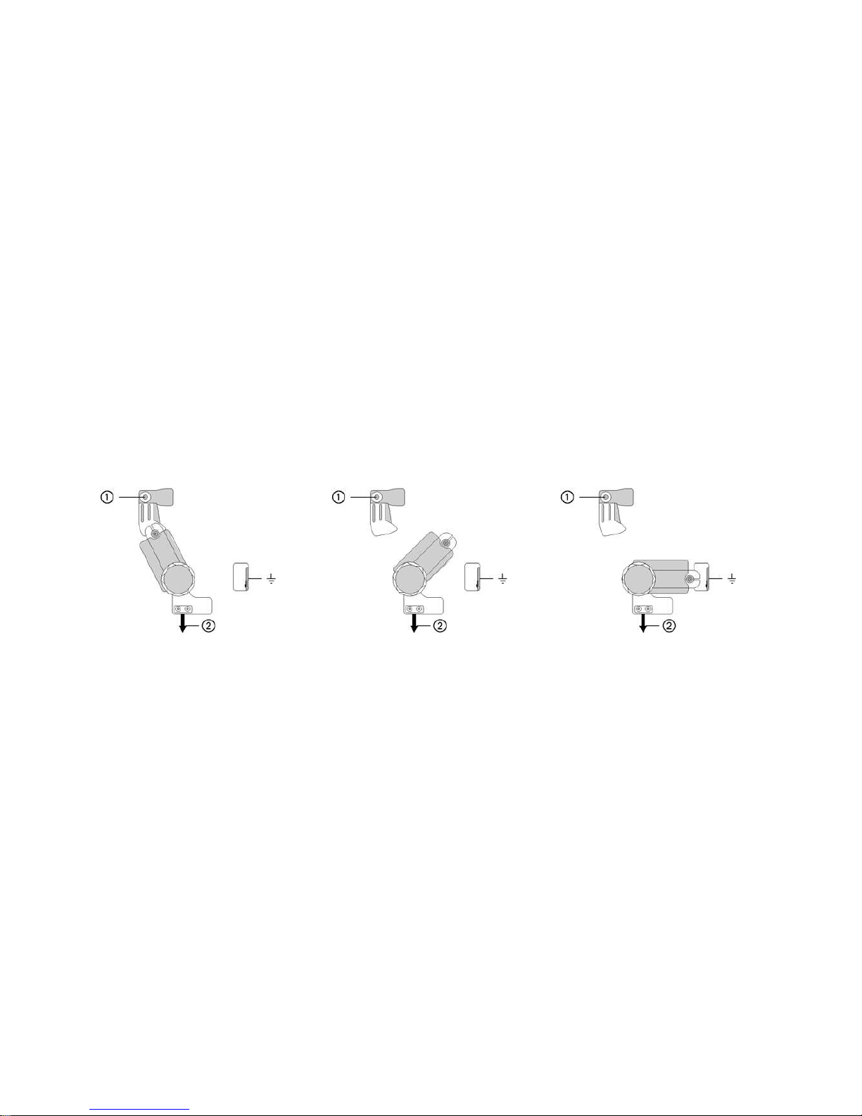
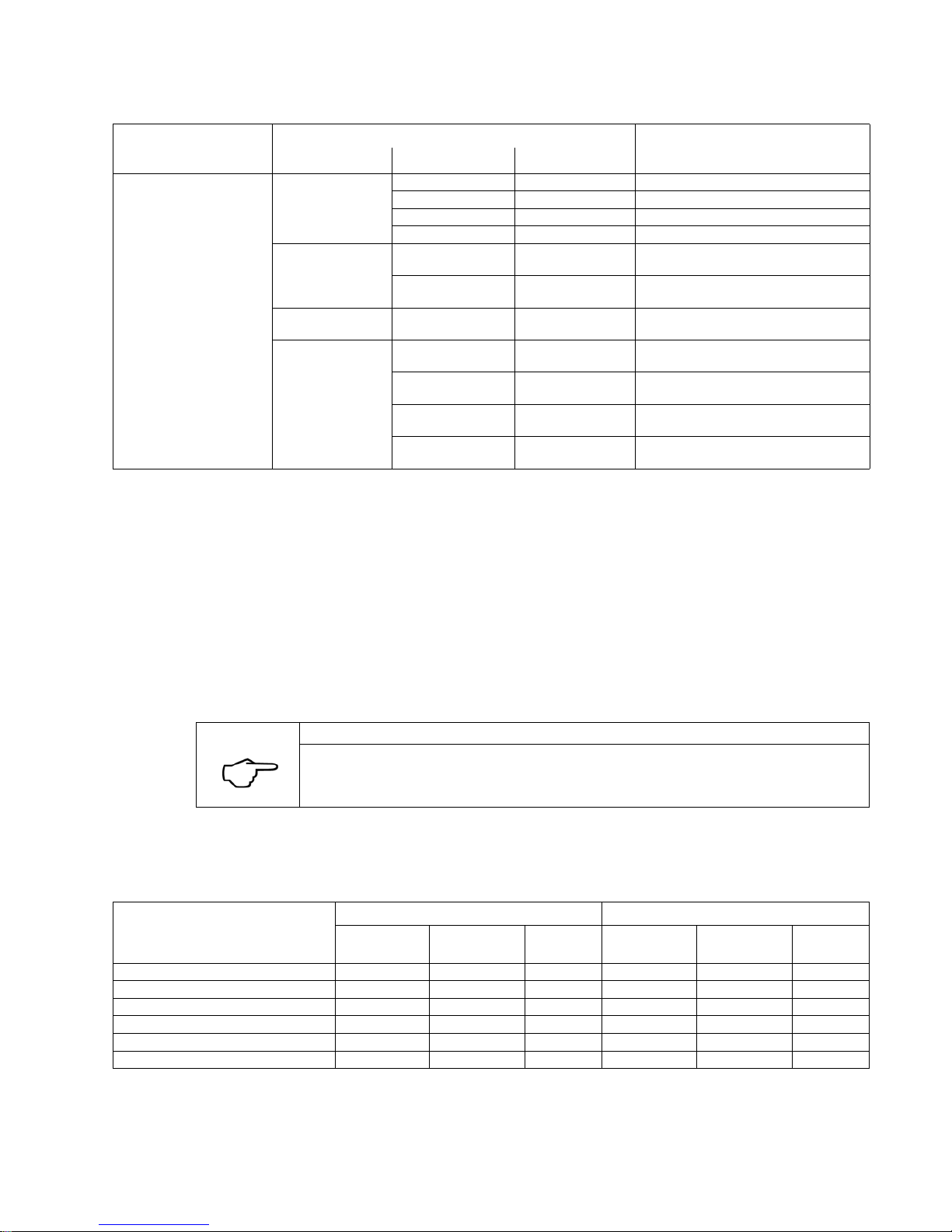
Switch positions of the three-position disconnector
CLOSED position OPEN position READY-TO-EARTH position
Busbar connection
Cable connection or circuit-breaker
Description
16/172 Revision 05 • INSTALLATION AND OPERATING INSTRUCTIONS • NXPLUS C Wind • 802-9074.9
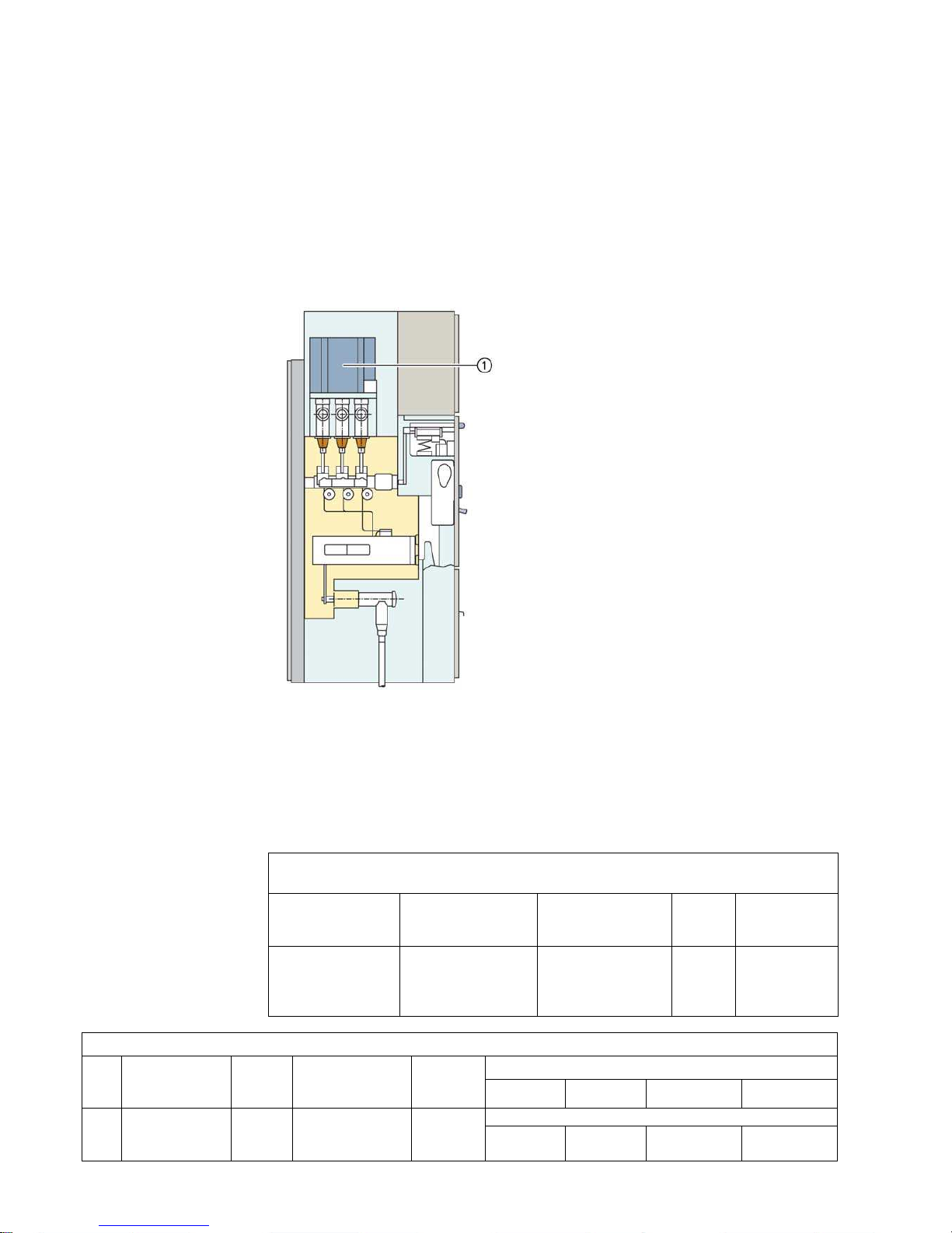
8.3 Operating mechanisms for the three-position disconnector
In NXPLUS C Wind switchgear, the three-position disconnector is used in a disconnector panel
or in combination with circuit-breakers in a circuit-breaker panel.
The three-position disconnector is operated from the switchgear front.
Equipment Auxiliary switch
Each operating mechanism is equipped with an auxiliary switch for the position indication.
Operating mechanism for three-position disconnector
Application:
• Circuit-breaker panel 630 A and 800 A
• Disconnector panel 630 A and 1000 A
Position indicator for three-position
disconnector (DISCONNECTING function)
Interrogation lever (only within circuit-breaker
panel)
Position indicator for three-position
disconnector (EARTHING/READY-TO-EARTH
function)
Ready-for-service indicator
Actuating opening for earthing switch
(EARTHING/READY-TO-EARTH function)
Actuating opening for disconnector
(DISCONNECTING function)
Control gate for opening the actuating openings
(can only be operated in the circuit-breaker
panel if the interrogation lever is pushed
downwards)
802-9074.9 • INSTALLATION AND OPERATING INSTRUCTIONS • NXPLUS C Wind • Revision 05 17/172
Description
8.4 Three-position switch-disconnector
Features • The three-position switch-disconnector is designed for a rated voltage of up to 36 kV.
• Switching functions as general-purpose switch-disconnector (class E3)
The three-position switch disconnector incorporates the functions of a switch-disconnector and
a make-proof earthing switch with the switch positions
•CLOSE
•OPEN
•EARTHED
Application
• Ring-main panel
Fig. 6: Operation of three-position switch
Mode of operation The operating shaft forms one unit together with the three contact blades. Due to the
arrangement of the fixed contacts (earth - busbar), it is not necessary to interlock the CLOSE
and EARTHING functions.
Closing operation During the closing operation, the operating shaft with the moving contact blades changes
from the OPEN to the CLOSED position.
The force of the spring-operated mechanism ensures a high closing speed and a reliable
connection of the main circuit.
Opening operation During the opening operation, the arc is caused to rotate by the arc-suppression system, thus
preventing the development of a fixed root. This very effective arc extinction provides short
arcing times. The isolating distance in gas established after opening fulfils the conditions for
isolating distances according to IEC/EN 62271-102 / VDE 0671-102, IEC/EN 62271-103 /
VDE 0671-103 and IEC/EN 62271-1 / VDE 0671-1.
Earthing operation The "EARTHING" operation is implemented by the turning movement of the operating lever
(rotation, if required) from the "OPEN" to the "EARTHED" position.

Description
18/172 Revision 05 • INSTALLATION AND OPERATING INSTRUCTIONS • NXPLUS C Wind • 802-9074.9
8.5 Operating mechanisms of three-position switch-disconnectors
Features • Mechanical endurance: 1000 operating cycles
• Manual operation with the help of a slip-on operating lever
• Option: Motor operation of the disconnecting function and earthing function
• Control board with accordingly cut-out switching gate prevents the three-position switchdisconnector from being switched directly from the CLOSED via the OPEN to the EARTHED
position.
• Two separate actuating openings are provided for unambiguous selection of either the loadbreak or make-proof earthing functions.
• Operation via rotary movement, operating direction according to IEC/EN 60 447 (VDN/VDEW
recommendation).
Spring-operated
mechanism
The spring-operated mechanism is used for the three-position switch-disconnector in ringmain panels (as ring-main switch). The switching movements are performed independently of
the operating speed.
Design The three-position switch-disconnector is operated through a gas-tight welded bushing at the
front of the switchgear vessel.
Options for all
operating mechanisms
• Motor operating mechanism
- Remote operation (standard) applied to terminal
- Local operation by momentary-contact rotary control switch in the low-voltage
compartment (option)
- Manual operation possible by operating lever
• Wiring
- Auxiliary switches and motor operating mechanisms are wired to terminal strips in the low-
voltage compartment.
Option for
ring-main feeder
• Auxiliary switch
- For switch-disconnector function: CLOSED and OPEN: 1 NO + 1 NC + 2 changeover
- For earthing switch function: CLOSED and OPEN: 1 NO + 1 NC + 2 changeover
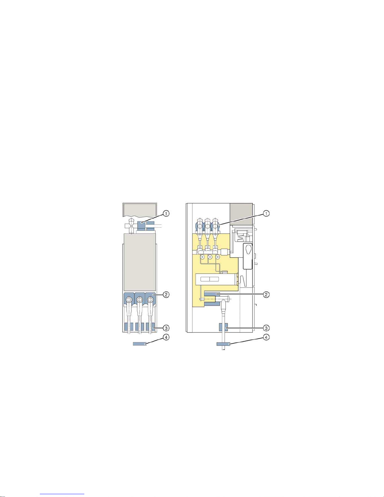
Fig. 7: Front operating mechanism in ring-main feeder
Ring-main feeder:
Ready-for-service
indicator
Manual operation of the
rotary lever mechanism
for the CLOSE function
Auxiliary switch (option)
Control gate/locking
device for three-position
switch-disconnector
Motor operating
mechanism (option)
Manual operation of the
rotary lever mechanism
for the EARTHING
function
Cable compartment
interlock
Capacitive voltage
detecting system at the
cable feeder
Position indicator for
three-position switchdisconnector
Capacitive voltage
detecting system on the
busbar (option)
802-9074.9 • INSTALLATION AND OPERATING INSTRUCTIONS • NXPLUS C Wind • Revision 05 19/172
Description
8.6 Voltage transformers
Features • According to VDE 0414-9-3 and IEC 61869-3
• Cast-resin insulated
•Inductive type
• Touchable due to metal enclosure
• Safe-to-touch due to metal cover
• Pluggable
• Arranged outside the primary enclosure (switchgear vessel)
Mounting location •On the busbar
Voltage transformer types Busbar voltage transformer
• Pluggable in the cross pieces of the busbar using adapters
• No separate metering panel required
• Repeat test at 80% of the rated short-duration power-frequency withstand voltage possible
with mounted voltage transformer
Electrical data
Busbar voltage transformer
Primary data for type 4MT2 36 kV
For operating voltages from 30 to 35 kV, rated voltage factor U
n
/8h = 1.9; Un/continuous = 1.2
Rated voltage [kV] Rated short-duration
power-frequency
withstand voltage [kV]
Rated lightning impulse
withstand voltage [kV]
Standard Operating voltage
[kV]
36 70 170 IEC 30/ √ 3;
33/ √ 3;
34.5/ √ 3
35/ √ 3
Secondary data
Type Operating voltage
[V]
Auxiliary
winding
Thermal limit current
(measuring winding)
[A]
Rated longtime current
8h [A]
Rating at accuracy class [VA]
0.2 0.5 1 3
4MT2 100/ √ 3;
110/ √ 3;
120/ √ 3
100/ √ 3;
110/ √ 3;
120/ √ 3
5 A 6 IEC
5, 10, 15, 20, 2510, 15, 20, 25,
30, 45
10, 15, 20, 25,
30, 45, 50, 60, 75
10, 15, 20, 25,
30, 45, 50, 60, 75
Description
20/172 Revision 05 • INSTALLATION AND OPERATING INSTRUCTIONS • NXPLUS C Wind • 802-9074.9
8.7 Current transformers
Features • According to VDE 0414-9-2 and IEC 61869-2
• Designed as ring-core current transformers, single-pole:
- Ring core as carrier of secondary winding
- Main circuit corresponds to primary winding
• Free of dielectrically stressed cast-resin parts (due to design)
• Arranged outside the primary enclosure (switchgear vessel) due to single-pole design of
cable connection
•Inductive type
•Certifiable
• Climate-independent
• Insulation class E
• Secondary connection by means of a terminal strip in the low-voltage compartment of the
panel
Mounting locations •Around the busbar
• At the panel connection
•Around the cable
Current transformer
types
• Busbar current transformer
- Inside diameter of transformer 56 mm
- Max. usable height 170 mm
• Feeder current transformer (only circuit-breaker panels)
- Inside diameter of transformer 106 mm
- Max. usable height 205 mm
• Cable-type current transformer for shielded cables
- Inside diameter of transformer 55 mm
- Max. usable height 170 mm
• Zero-sequence current transformer underneath the panels (included in the scope of supply);
on-site installation
Front view: Side view:
Busbar current
transformer
Feeder current
transformer
Cable-type current
transformer
Zero-sequence current
transformer
802-9074.9 • INSTALLATION AND OPERATING INSTRUCTIONS • NXPLUS C Wind • Revision 05 21/172
Description
Electrical data
8.8 Busbar system
Fig. 8: Busbar system 630 A/1000 A
The busbar is single-pole insulated with silicone rubber. Each phase has an earthed layer on
the outside (screened busbar system). This design makes the busbar independent of climatic
effects.
As the busbar system is arranged outside the gas compartment, extension or panel
replacement is possible within a very short period of time without requiring any gas work.
Current transformer type 4MC 4MC7032 (core height 80
mm)
WIC
Operating voltage max. 0.8 kV max. 0.8 kV max. 0.8 kV
Rated short-duration power- frequency
withstand voltage (winding test)
3kV 3kV 3kV
Rated frequency 50/60 Hz 50/60 Hz 50/60 Hz
Rated continuous thermal current max. 1.2 x rated current
(primary)
max. 1.2 x rated current
(primary)
max. 1.2 x rated current (primary)
Rated thermal short-time current, max. 1 s up to 25 kA up to 25 kA up to 25 kA
Rated current dynamic unlimited unlimited unlimited
primary 40 A to 600 A 40 A to 600 A 14.4 A - 57.6 A to 115.2 A - 490.8 A
secondary 1 A and 5 A 1 A and 5 A 0.075 A to 0.3 A
Multiratio (secondary) 100 - 50 A to 600 - 300 A 100 - 50 A to 600 - 300 A Core data according to rated primary current max. 3 cores max. 3 cores max. 2 cores
Measuring core Rating 2.5 VA to 10 VA 2.5 VA to 10 VA -
Class 0.2 to 1 0.2 to 1 -
Overcurrent
factor
M10 M10 -
Protection core Rating 2.5 VA to 30 VA 2.5 VA to 30 VA 0.1 VA
Class 5 or 10 5 or 10 5 or 10
Overcurrent
factor
P10 to P30 P10 to P30 P80
Permissible ambient air temperature max. 60 °C max. 60 °C max. 60 °C
Insulation class E E E

Description
22/172 Revision 05 • INSTALLATION AND OPERATING INSTRUCTIONS • NXPLUS C Wind • 802-9074.9
8.9 Cable connection
Possible combinations of cable connection types (T-plugs, coupling inserts) and
surge arresters in NXPLUS C Wind up to 36 kV
For gas-insulated switchgear NXPLUS C Wind, basically only cable plugs shielded by means of
an external semi-conductive layer (also called screened cable T-plugs) can be used. This
external semi-conductive layer must be earthed. Earthing is normally done through a cable
connection.
Insulated cable T-plugs (without external semi-conductive layer) are not permissible, as this
plug type often produces partial discharges due to the proximity to earthed parts of the
switchgear. Partial discharges destroy the cable T-plug, causing an arc between phase and
earth.
The connection of conventional cable sealing ends via elbow adapters, e.g. type AKE, is not
permissible either, as this connection system is also insulated and not screened (no external
semi-conductive layer).
Circuit-breaker panels 630 A / 800 A
Number
of cables
per panel
and phase
Make Rated
voltage
Conductor crosssection
1)
Insulation T-plugs/phase Coupling inserts/
coupling plugs
Surge arresters with coupling inserts
[mm2]
bolted bolted Arresters/phase Coupling
unit
1Nexans
Euromold
36 50 to 240 EPDM 1x M400TB/G – 1x 400PB-5(10)SA-xxx –
36 50 to 240 EPDM 1x M430TB/G – 1x 300SA-10-xx –
36 50 to 630 EPDM 1x M484TB/G – 1x 800SA-10-xx –
36 300 to 630 EPDM 1x M440TB/G – 1x 400PB-5(10)SA-xxx –
Südkabel 36 70 to 300 Silicone 1x SET 36 – – –
36 70 to 500 Silicone 1x SEHT 33 – 1x MUT 33 1x KU 33
nkt cables 36 25 to 300 Silicone 1x CB 36-630 – 1x CSA36-10 –
36 400 to 630 Silicone 1x CB 36-
630(1250)
– 1x CSA36-10 –
Tyco Electronics
Raychem
36 25 to 300 Silicone 1x RSTI-66xx – 1x RSTI-CC-66SAxxx –
36 25 to 300 Silicone 1x RSTI-68xx – – –
36 400 to 630 Silicone 1x RSTI-66Lxx – 1x RSTI-66SAxxx 1x RSTI-
66CP-M16
36 400 to 800 Silicone 1x RSTI-69xx – – –
2Nexans
Euromold
36 50 to 240 EPDM 2x M400TB/G 1x M400CP – –
36 50 to 240 EPDM 1x M430TB/G 1x M300PBM-630A 1x 300SA-10-xx –
36 50 to 360 EPDM 1x M484TB/G 1x M804PB/G – –
36 300 to 630 EPDM 2x M440TB/G 1x M400CP – –
Südkabel 36 70 to 500 Silicone 2x SEHT 33 1x KU 33 – –
nkt cables 36 25 to 300 Silicone 1x CB 36-630 1x CC36-630 1x CSA36-10 –
36 25 to 300 Silicone 2x CB 36-630 1x CP 630C – –
36 400 to 630 Silicone 2x CB 36-
630(1250)
1x CC36-630(1250) 1x CSA36-10 –
36 400 to 630 Silicone 2x CB 36-
630(1250)
1x CP 630C – –
Tyco Electronics
Raychem
36 25 to 300 Silicone 1x RSTI-66xx 1x RSTI-CC-66xx – –
36 25 to 300 Silicone 1x RSTI-68xx 1x RSTI-CC-68xx – –
36 400 to 630 Silicone 2x RSTI-66Lxx 1x RSTI-66CP-M16 – –
36 400 to 800 Silicone 1x RSTI-69xx 1x RSTI-CC-69xx – –
1)
Observe the actual short-circuit and current carrying capacity of the cables and sealing ends.

802-9074.9 • INSTALLATION AND OPERATING INSTRUCTIONS • NXPLUS C Wind • Revision 05 23/172
Description
Disconnector panel 630 A / 800 A, ring-main panel 630 A
Number
of cables
per panel
and phase
Make Rated
voltage
Conductor crosssection
1)
Insulation T-plugs/phase Coupling inserts/
coupling plugs
Surge arresters with coupling inserts
[mm2]
bolted bolted Arresters/phase Coupling unit
1Nexans
Euromold
36 50 to 240 EPDM 1x M400TB/G – 1x 400PB 5(10) SA-xxx –
36 50 to 240 EPDM 1x M430TB/G – 1x 300SA-10-xx –
36 50 to 630 EPDM 1x M484TB/G - 1x 800SA-10-xx –
36 300 to 630 EPDM 1x M440TB/G – 1x 400PB 5(10) SA-xxx –
Südkabel 36 70 to 500 Silicone 1x SET 36 – – –
36 70 to 500 Silicone 1x SEHT 33 – 1x MUT33 1x KU33
nkt cables 36 25 to 300 Silicone 1x CB36-630 – 1x CSA36-10 –
36 400 to 630 Silicone 1x CB36-
630(1250)
–1x CSA36-10–
Tyco
Electronics
Raychem
36 25 to 300 Silicone 1x RSTI-66xx – 1x RSTI-CC-66SAxxx –
36 25 to 300 Silicone 1x RSTI-68xx – – –
36 400 to 630 Silicone 1x RSTI-66Lxx – 1x RSTI-CC-66SAxxx 1x RSTI-66CP-
M16
36 400 to 800 Silicone 1x RSTI-69xx – – –
2Nexans
Euromold
36 50 to 240 EPDM 2x M400TB/G 1x M400CP – –
36 50 to 240 EPDM 1x M430TB/G 1x M300PB/G – –
36 50 to 630 EPDM 1x M484TBG 1x M804PB/G 1x 800SA-10-xx –
36 300 to 630 EPDM 2x M440TB/G 1x M400CP – –
Südkabel 36 70 to 500 Silicone 2x SEHT 33 1x KU33 – –
nkt cables 36 25 to 300 Silicone 1x CB36-630 1x CC36-630 1x CSA36-10 –
36 25 to 300 Silicone 2x CB36-630 1x CP-630C 1x CSA36-10 –
36 400 to 630 Silicone 1x CB36-
630(1250)
1x CC36630(1250)
1x CSA36-10 –
36 400 to 630 Silicone 2x CB36-
630(1250)
1x CP-630C – –
Tyco
Electronics
Raychem
36 25 to 300 Silicone 1x RSTI-66xx 1x RSTI-CC-66xx 1x RSTI-CC-66SAxxx–
36 25 to 300 Silicone 1x RSTI-68xx 1x RSTI-CC-68xx – –
36 400 to 630 Silicone 2x RSTI-66Lxx 1x RSTI-66CP-M16 1x RSTI-CC-66SAxxx 1x RSTI-66CP-
M16
36 400 to 800 Silicone 1x RSTI-69xx 1x RSTI-CC-69xx – –
3Nexans
Euromold
36 50 to 240 EPDM 1x M430TB/G 1x M300PBM-
630A
––
nkt cables 36 25 to 300 Silicone 1x CB36-630 2x CC36-630 – –
36 2x CP-630C – –
36 400 to 630 Silicone 1x CB 36-
630(1250)
2x CC36630(1250)
––
36 400 to 630 Silicone 2x CB 36-
630(1250)
1x CP-630C – –
Tyco
Electronics
Raychem
36 25 to 300 Silicone 1x RSTI-66xx 2x RSTI-CC-66xx – –
36 25 to 300 Silicone 1x RSTI-68xx 2x RSTI-CC-68xx – –
36 400 to 630 Silicone 3x RSTI-66Lxx 2x RSTI-66CP-M16 – –
36 400 to 800 Silicone 1x RSTI-69xx 2x RSTI-CC-69xx – –
1)
Observe the actual short-circuit and current carrying capacity of the cables and sealing ends.
Description
24/172 Revision 05 • INSTALLATION AND OPERATING INSTRUCTIONS • NXPLUS C Wind • 802-9074.9
Thermoplastic-insulated
cables ≤ 36 kV
according to IEC 60 502-2 and VDE 0276-620
Cable T-plug connection • Connection of cable T-plugs suitable for bushings with outside cone as interface type C
according to EN 50181
• Connection cross-sections up to 800 mm
2
Surge arresters • Pluggable on cable T-plug (Nexans Euromold, Tyco Electronics Raychem, nkt cables and
Südkabel)
• Surge arresters recommended
- if, at the same time, the cable system is directly connected to the overhead line.
- if, at the same time, the protection zone of the surge arrester at the end tower of the
overhead line does not cover the switchgear.
- in offshore wind farms.
Check of mounting space Surge arresters are used only with one cable connected per phase. Some types of surge
arresters exceed the permissible dimensions. The following table informs about possible
combinations (x):
Cable type Cable sealing end Comment
Make Type
Cross-section [mm2]
1-core cable, PE and XLPEinsulated
N2YSY (Cu) and N2XSY (Cu)
or
NA2YSY (Al) and NA2XSY (Al)
Nexans Euromold M400TB/G 50 to 240 EPDM with semi-conductive layer
M430TB/G 50 to 240 EPDM with semi-conductive layer
M484TB/G 70 to 630 EPDM with semi-conductive layer
M440 TB/G 300 to 630 EPDM with semi-conductive layer
nkt cables CB 36-630 25 to 300 Silicone with semi-conductive layer
(optionally with metal housing)
CB 36-630(1250) 400 to 630 Silicone with semi-conductive layer
(optionally with metal housing)
Südkabel SEHDT 33 70 to 500 Silicone with semi-conductive layer
(optionally with metal housing)
Tyco Electronics
Raychem
RSTI-66xx 25 to 240 Silicone with semi-conductive layer, with
capacitive measuring point
RSTI-68xx 25 to 240 Silicone with semi-conductive layer, with
capacitive measuring point
RSTI-66Lxx 400 to 630 Silicone with semi-conductive layer, with
capacitive measuring point
RSTI-69xx 400 to 800 Silicone with semi-conductive layer, with
capacitive measuring point
NOTE!
Cable T-plugs and surge arresters must be from the same manufacturer, see page 22,
"Possible combinations of cable connection types (T-plugs, coupling inserts) and surge
arresters in NXPLUS C Wind up to 36 kV".
Surge arrester type 1 cable per phase 2 cables per phase
Circuit-breaker
panel
Disconnector
panel
Ring-main
panel
Circuit-breaker
panel
Disconnector
panel
Ring-main
panel
Nexans Euromold 400PB-10-SA-45L X X X – – –
Nexans Euromold 300SA-10-xx X X X X X X
Südkabel MUT 33 + KU 33 – * X X – – –
nkt cables CSA 36-10 X X X X** X X
Tyco Electronics Raychem RSTI-CC-66SAxxx –* X X –* X X
Tyco Electronics Raychem RSTI-66SAxxx –* X X –* X X
* protrudes into the floor area; possible depending on the local conditions, e.g. with sufficient hole depth
** depending on the plug type (see page 22, "Possible combinations of cable connection types (T-plugs, coupling inserts) and surge arresters in
NXPLUS C Wind up to 36 kV")
802-9074.9 • INSTALLATION AND OPERATING INSTRUCTIONS • NXPLUS C Wind • Revision 05 25/172
Description
8.10 Ready-for-service indicator
Features • Self-monitoring, easy to read
• Independent of temperature and pressure variations
• Independent of the site altitude
• Only responds to changes in gas density
• Option: Alarm switch 1NO + 1NC for remote electrical indication
• Contactless detection of gas monitoring
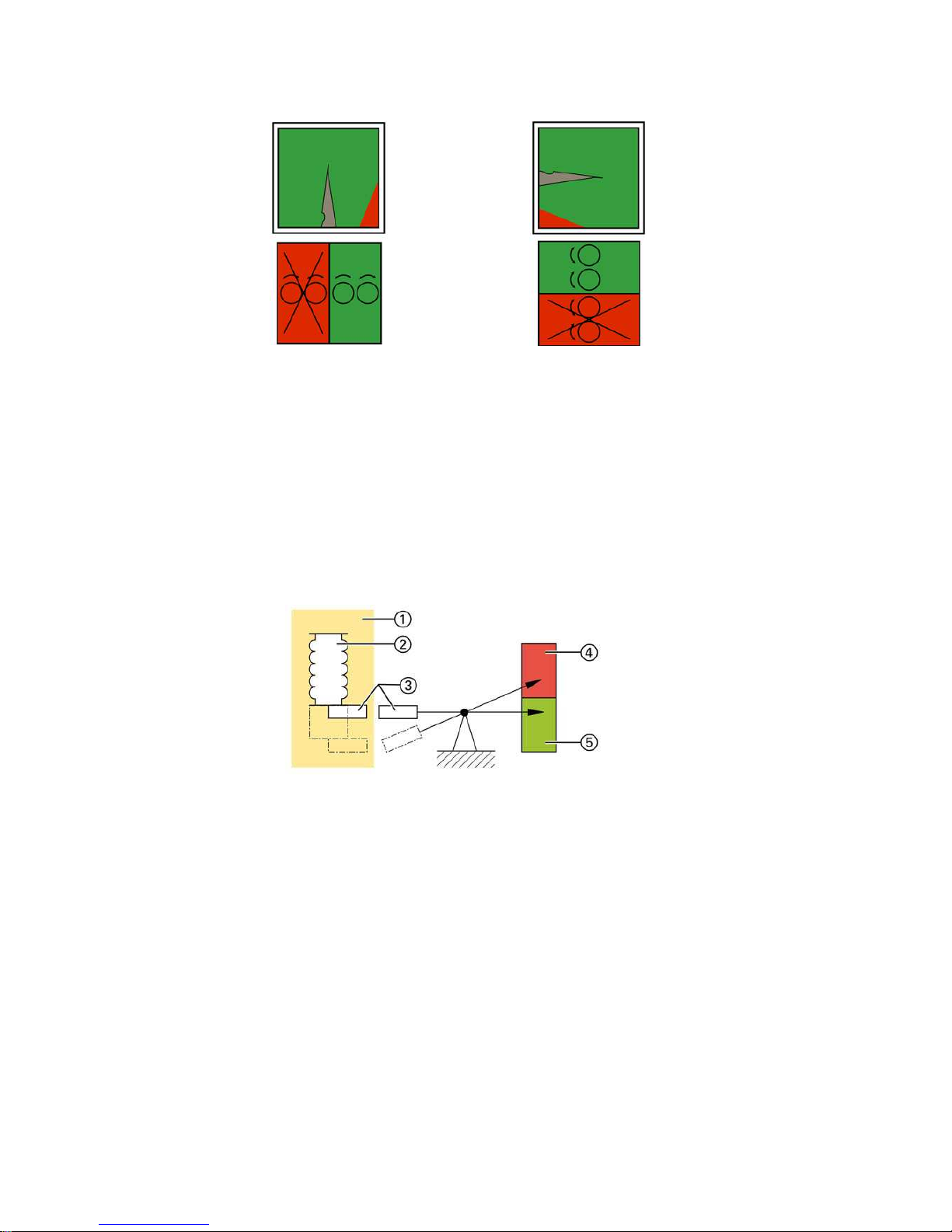
Mode of operation
For the ready-for-service indicator, a gas-tight measurement box is installed inside the
switchgear vessel. A coupling magnet transmits the position of the measurement box to an
armature located outside the switchgear vessel. This armature moves the ready-for-service
indicator of the switchgear.
Thermal variations of the gas pressure are compensated, as the gas available in the
measurement box and in the vessel expands in the same way when it gets warm. A change of
the gas density in the switchgear vessel caused by a leak is indicated due to the pressure
difference between the switchgear vessel and the measurement box. The gas density is
decisive for the insulating capacity.
Fig. 9: Ready-for-service indicator
on the front plate
(disconnector panel,
circuit-breaker panel)
Fig. 10: Ready-for-service indicator
on the front plate
(ring-main panel)
Fig. 11: Gas monitoring principle
Stainless-steel vessel filled
with SF
6
gas
Measurement box in stainlesssteel vessel filled with SF
6
gas
Magnetic coupling
Red indication: not ready for
service
Green indication: ready for
service
Description
26/172 Revision 05 • INSTALLATION AND OPERATING INSTRUCTIONS • NXPLUS C Wind • 802-9074.9
8.11 Interlocks
• The three-position disconnector is equipped with a mechanical interlock. This interlock
prevents the circuit-breaker from being closed while the three-position disconnector is
being operated. Furthermore the mechanical interlock prevents the three-position
disconnector from being operated while the circuit-breaker is closed.
• The switching gate prevents switching straight from CLOSED to READY-TO-EARTH or from
READY-TO-EARTH to CLOSED, as the operating lever must be re-inserted in the OPEN
position.
• The control gate of the switching gate of the three-position switch can be padlocked in all
three switch positions.
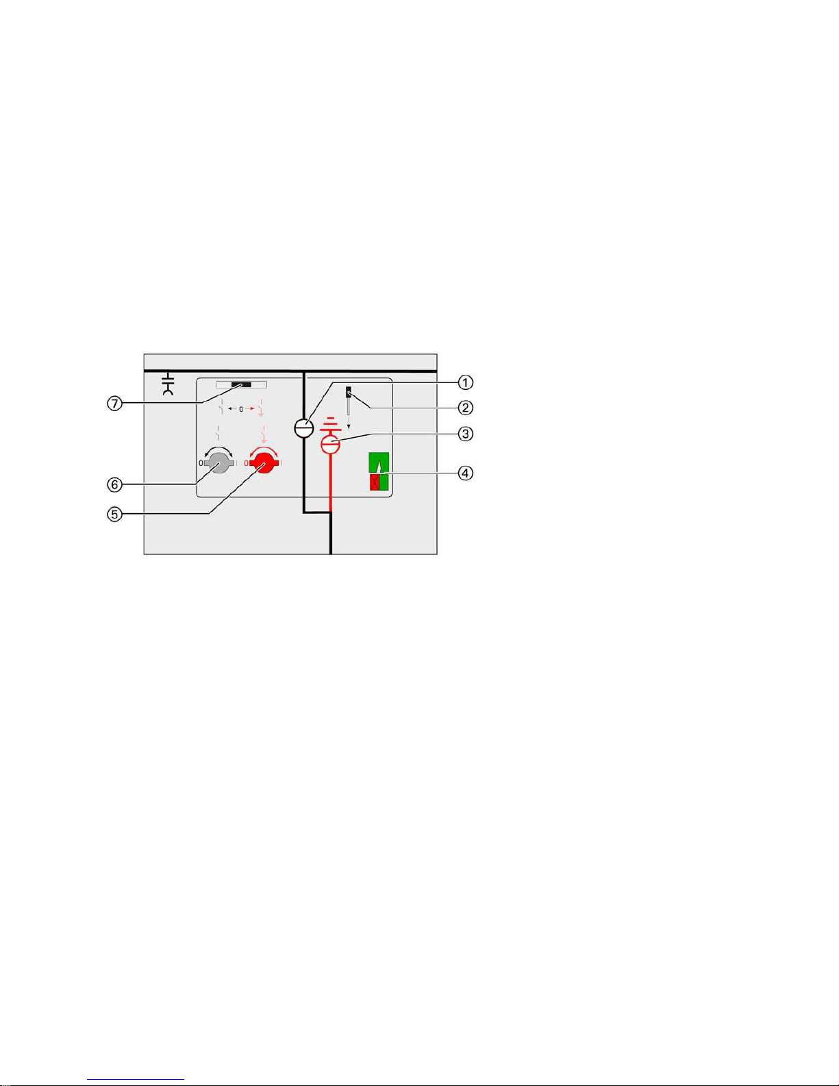
Circuit-breaker panel/disconnector panel
Ring-main panel
Optional interlocks:
• Mechanical interlocking between feeder locking device and three-position disconnector
(circuit-breaker only lockable in earthed position)
• Mechanical interlocking between feeder locking device, three-position disconnector and
cable compartment cover (circuit-breaker only lockable in earthed position, cable
compartment cover only removable in earthed position)
• Mechanical interlocking between feeder locking device, three-position disconnector and
cable compartment cover (circuit-breaker only lockable in earthed position, cable
compartment cover only removable in earthed position) with key-operated interlock
• Mechanical interlocking between the three-position switch and the cable compartment
cover (cable compartment cover only removable in earthed position)
• Mechanical interlocking between the three-position switch and the cable compartment
cover (cable compartment cover only removable in earthed position) with key-operated
interlock
• Electromagnetic interlocking of the actuating openings for the three-position switch
• A closing lock-out (option) in the ring-main panel prevents the three-position switchdisconnector from being switched to the CLOSED position if the cable compartment cover is
removed.
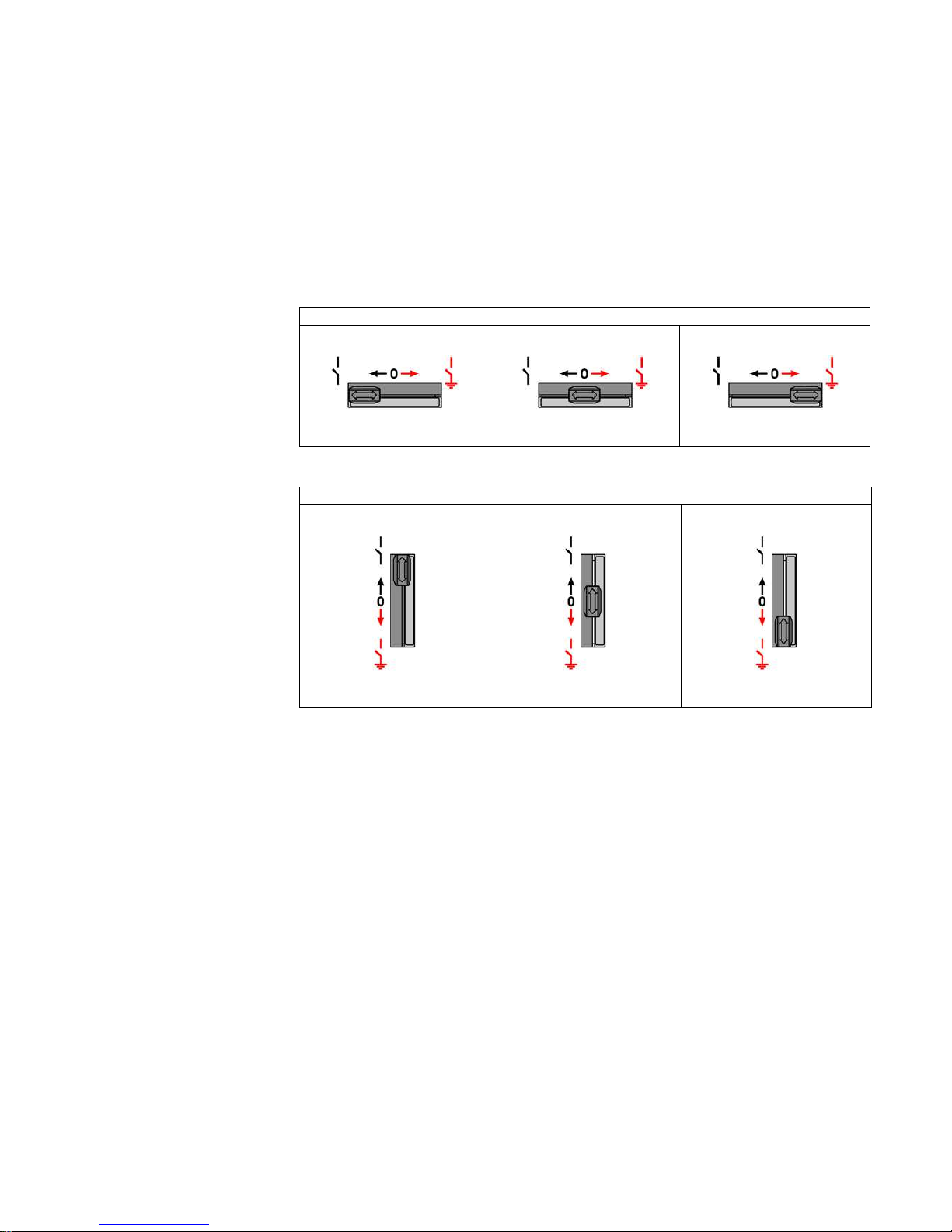
Control gate lever in position:
Left Center Right
The three-position switch can be
operated
Switching operation not possible READY-TO-EARTH/EARTHING
possible
Control gate lever in position:
Up Center Down
The three-position switch can be
operated
Switching operation not possible READY-TO-EARTH/EARTHING
possible
802-9074.9 • INSTALLATION AND OPERATING INSTRUCTIONS • NXPLUS C Wind • Revision 05 27/172
Description
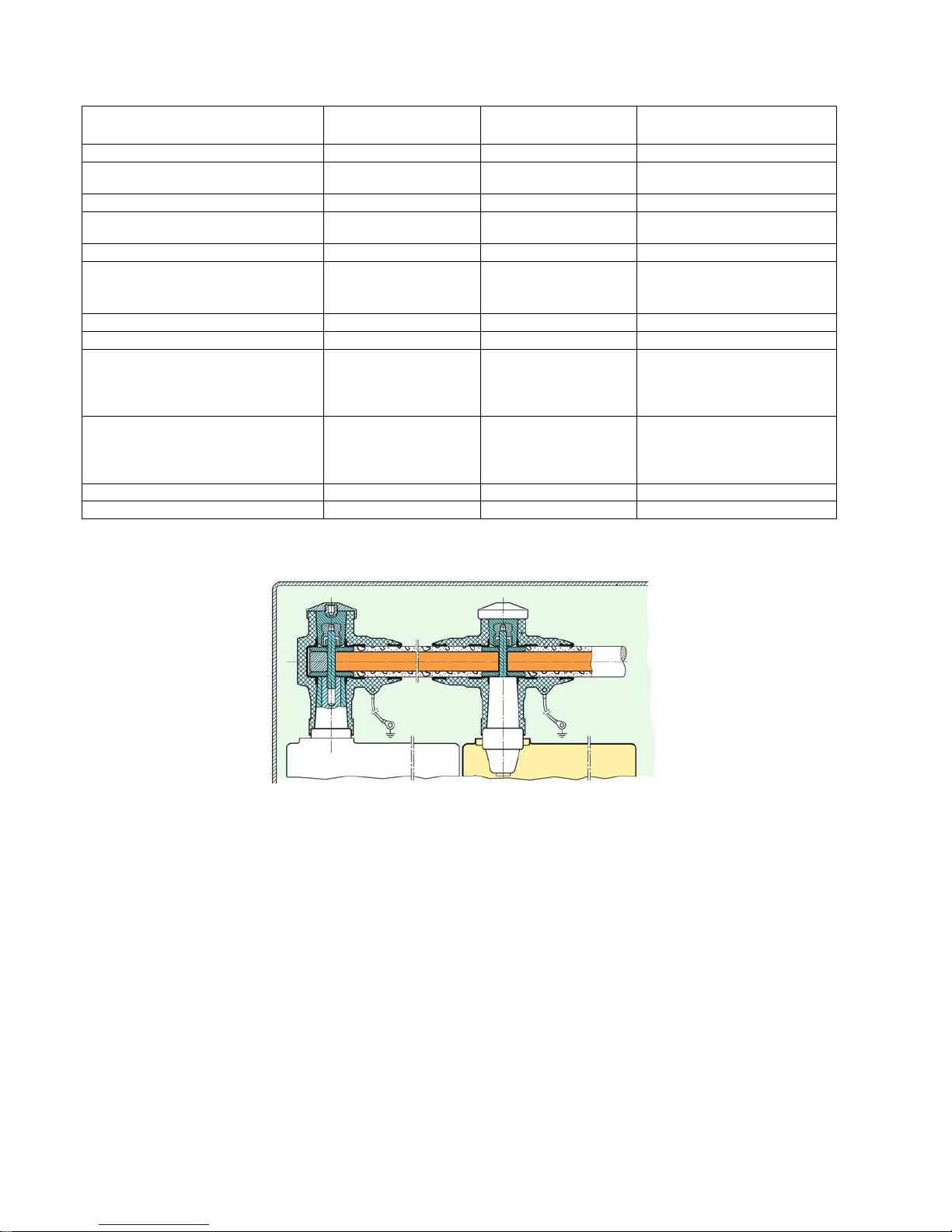
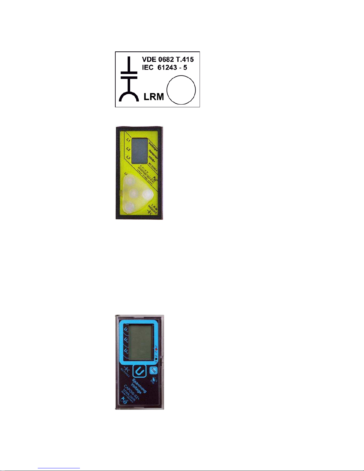
8.12 Voltage detecting systems
For voltage detection according to IEC 61243-5 and VDE 0682 Part 415 with the following
voltage detecting systems:
• LRM plug-in sockets
• VOIS+, VOIS R+ (option)
• CAPDIS -S1/-S2+ (option)
• WEGA 1.2/2.2 (option)
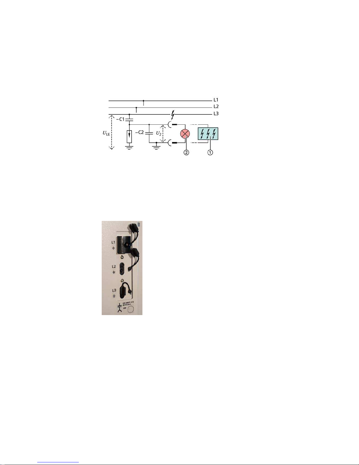
• -C1: Capacitance integrated into bushing
• -C2: Capacitance of the connection leads and the voltage indicator to earth
•U
LE=UN
/ √ 3 during rated operation in the three-phase system
•U2=UA=Voltage at the capacitive interface of the switchgear or at the voltage indicator
LRM plug-in sockets
Fig. 13: LRM plug-in sockets
Features of LRM
plug-in sockets
• Verification of safe isolation from supply phase by phase through insertion of the voltage
indicator in the corresponding plug-in sockets
• Voltage indicator suitable for continuous operation
•Safe-to-touch
•Routine-tested
• Measuring system and voltage indicator can be tested
• Voltage indicator flashes if high voltage is present
• Fixed-mounted capacitive voltage dividers in the bushings
Fig. 12: Voltage detecting system via capacitive voltage divider
(principle)
VOIS, WEGA,
CAPDIS-S1+/S2+
fixed-mounted
LRM indicator plugged in
Description
28/172 Revision 05 • INSTALLATION AND OPERATING INSTRUCTIONS • NXPLUS C Wind • 802-9074.9
The marking for documentation of the repeat test of the interface condition is located next to
the LRM plug-in sockets:
Fig. 14: Documentation to repeat test of interface condition
VOIS+, VOIS R+
Fig. 15: Voltage indicator type VOIS+
Features of
VOIS+, VOIS R+
• Integrated display, without auxiliary power
• With indication "A1" to "A3" (see page 153, "Indications VOIS, VOIS R+, CAPDIS -S1+/-S2+")
• Maintenance-free, repeat test required
• With integrated 3-phase test socket for phase comparison (also suitable for plug-in voltage
indicator)
• Degree of protection IP 54, temperature range -25 °C to +55°C
• With integrated signaling relays (only VOIS R+)
• "M1": Operating voltage present at one phase L1, L2 or L3 as a minimum
• "M2": Operating voltage not present at L1, L2 and L3
CAPDIS-Sx+
Fig. 16: Voltage indicator type CAPDIS -S2+ (option)
802-9074.9 • INSTALLATION AND OPERATING INSTRUCTIONS • NXPLUS C Wind • Revision 05 29/172
Description
Common features of
CAPDIS -S1+/-S2+
• Maintenance-free
• Integrated display, without auxiliary power
• Integrated repeat test of the interfaces (self-monitoring)
• With integrated function test (without auxiliary power) by pressing the "Test" button
• Adjustable to different operating voltage ranges
• With integrated 3-phase test socket for phase comparison (also suitable for plug-in voltage
indicator)
• Degree of protection IP 54, temperature range –25 °C to +55 °C
• With signal-lead test
• With overvoltage monitoring and signaling at 1.2 times operating voltage
Features of CAPDIS-S1+ • Without auxiliary power
• With indication "A1" to "A7" (see page 153, "Indications VOIS, VOIS R+, CAPDIS -S1+/-S2+")
• Without ready-for-service monitoring
• Without signaling relay (thus without auxiliary contacts)
Features of CAPDIS-S2+ • With indication "A0" to "A8" (see page 153, "Indications VOIS, VOIS R+, CAPDIS -S1+/-S2+")
• Only by pressing the "Test" pushbutton: "ERROR" indication (A8), e.g. in case of missing
auxiliary voltage
• With ready-for-service monitoring (external auxiliary power required)
• With integrated signaling relay for signals "M1" to ”M4” (auxiliary power required):
- "M1": Voltage present at phases L1, L2, L3
- "M2": Voltage not present at L1, L2 and L3 (= active zero indication)
- "M3": Earth fault or voltage failure, e.g. in one phase
- "M4": External auxiliary power missing (with operating voltage present or not)
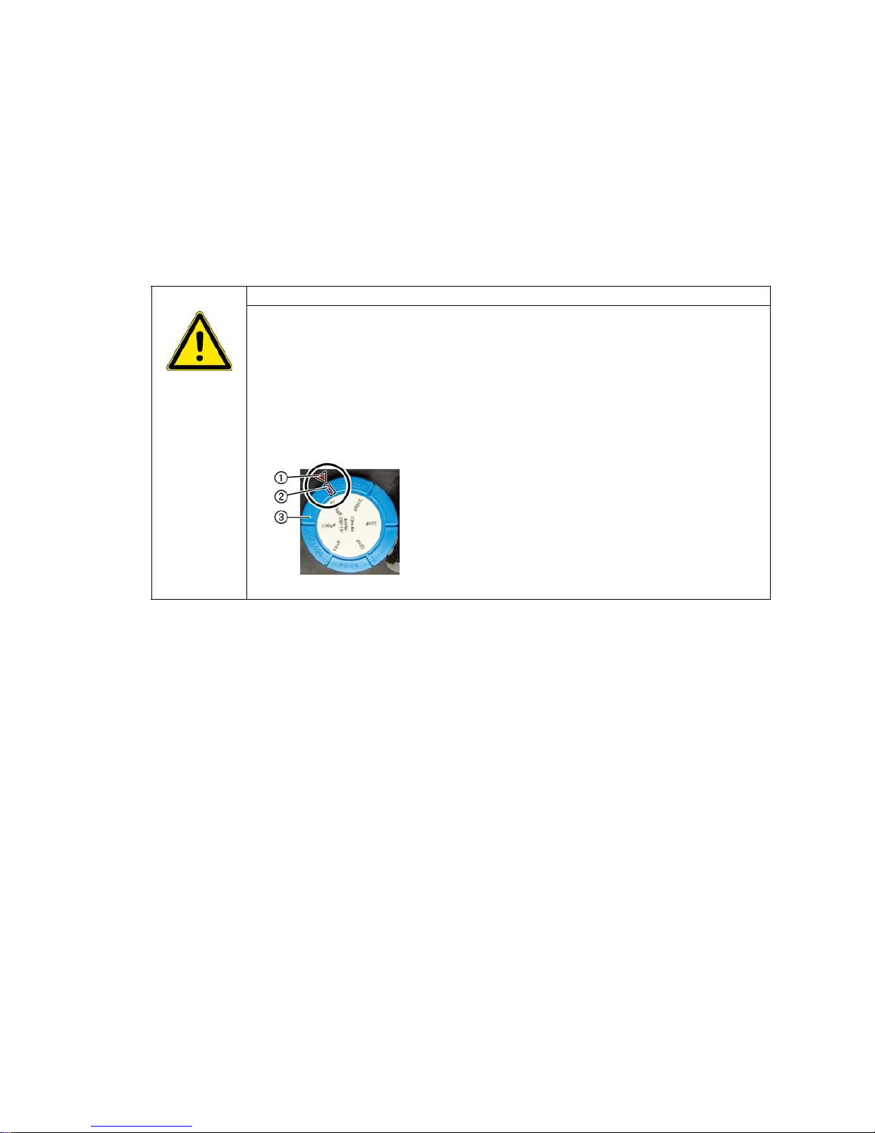
DANGER!
High voltage! Danger! Do only modify the factory setting of the C2 module in the voltage
detecting system CAPDIS-S1+/S2+ after consultation with the regional Siemens representative!
If the setting of the C2 module was modified by mistake, re-establish the factory setting as
follows:
- Pull out the C2 module at the rear side of CAPDIS-S1+/S2+
-Plug the C2 module into CAPDIS-S1+/S2+ so that the marked arrow on the housing
points to the marking on the C2 module
Fig. 17: Marking of the factory setting at the C2 module
Description
30/172 Revision 05 • INSTALLATION AND OPERATING INSTRUCTIONS • NXPLUS C Wind • 802-9074.9
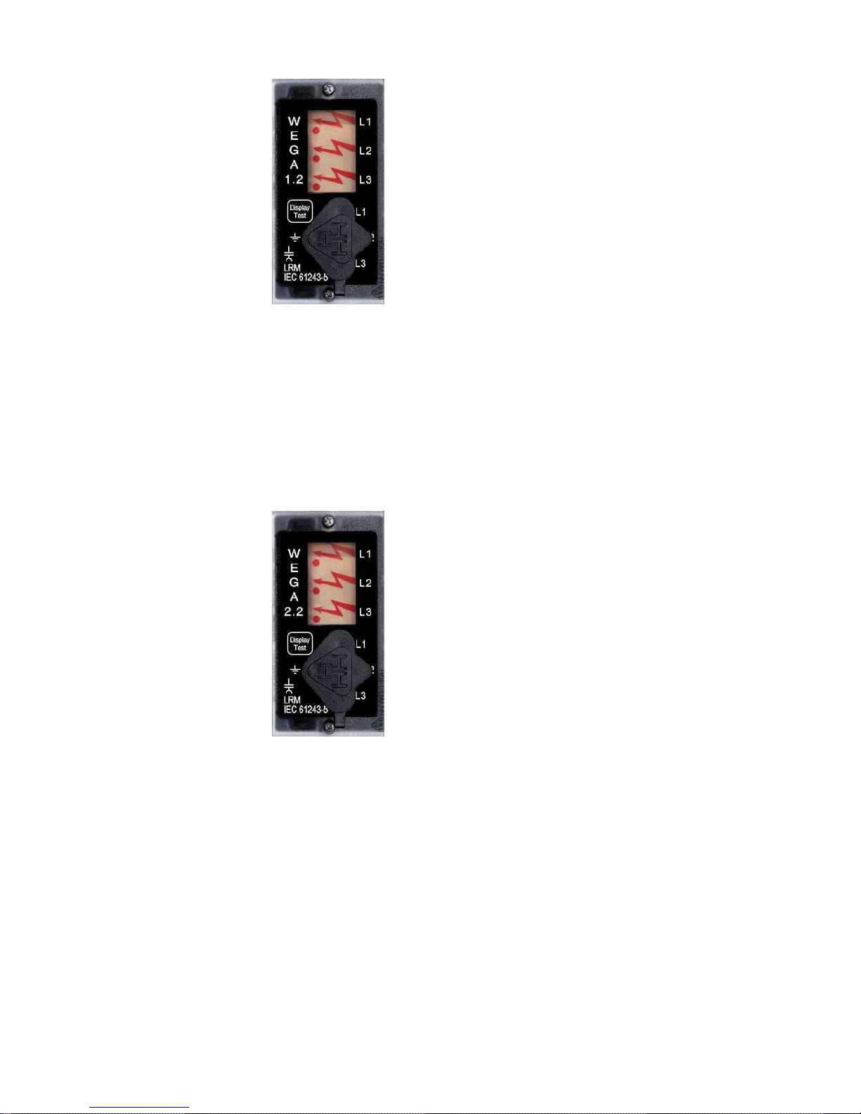
WEGA 1.2
Fig. 18: Voltage indicator type WEGA 1.2
Features of WEGA 1.2 • With indication "A1" to "A5" (see page 155, "Indications WEGA 1.2, WEGA 2.2")
• Maintenance-free
• Integrated repeat test of the interface (self-monitoring)
• With integrated function test (without auxiliary power) by pressing the "Display Test" button
• With integrated 3-phase LRM test socket for phase comparison
• Degree of protection IP 54, temperature range –25 °C to +55 °C
• Without integrated signaling relay
• Without auxiliary power
WEGA 2.2
Fig. 19: Voltage indicator type WEGA 2.2
Features of WEGA 2.2 • With indication "A0" to "A6" (see page 155, "Indications WEGA 1.2, WEGA 2.2")
• Maintenance-free
• Integrated repeat test of the interface (self-monitoring)
• With integrated function test (without auxiliary power) by pressing the "Display Test" button
• With integrated 3-phase LRM test socket for phase comparison
• Degree of protection IP 54, temperature range –25 °C to +55 °C
• With integrated signaling relay
• Auxiliary power required
 Loading...