

Siemens optiPoint key module, optiPoint BLF, optiPoint application module, optiPoint signature module, optiPoint display module Installation Instructions Manual
Page 1

optiPoint
Montageanleitung für
Beistellgeräte, Adapter und Zubehör
Installation instructions for accompanying
equipment, adapters and accessories
Notice de montage pour
satellites, adaptateurs et accessoires
Montage-instructie voor uitbreidingsterminals, toebehoren en adapters
Istruzioni di montaggio per
apparecchi ausiliari, adattatori ed accessori
Instrucciones de montaje para aparatos
auxiliares, adaptadores y accesorios
Instruções de montagem para aparelhos
suplementares, acessórios e adaptadores
Page 2
2
Page 3
optiPoint key module / optiPoint BLF / optiPoint signature module /
optiPoint display module / optiPoint application module / self labelling key module
optiPoint adapter
3
Page 4

쮕
খ
Beschreibung siehe ab Æ 9
For description, see from Æ 33 onward
Description : voir à partir de la page Æ 57
Omschrijving zie vanaf Æ 81
Descrizione a partire da Æ 105
Descripción a partir de Æ 129
Descrição ver a partir de Æ 154
4
Page 5

Ø Deutsch
Beistellgeräte . . . . . . . . . . . . . . . . . . . . . . . . . . . . . . . . . . . . . . . . . . . 9
optiPoint key module/optiPoint BLF. . . . . . . . . . . . . . . . . . . . . . . . . . . . . . . . . 9
optiPoint signature module . . . . . . . . . . . . . . . . . . . . . . . . . . . . . . . . . . . . . . 10
optiPoint display module/optiPoint application module . . . . . . . . . . . . . . . . . 11
optiPoint self labelling key module. . . . . . . . . . . . . . . . . . . . . . . . . . . . . . . . . 12
optiPoint acoustic adapter . . . . . . . . . . . . . . . . . . . . . . . . . . . . . . . . . . . . . . . 13
optiPoint analog adapter . . . . . . . . . . . . . . . . . . . . . . . . . . . . . . . . . . . . . . . . 14
optiPoint ISDN adapter . . . . . . . . . . . . . . . . . . . . . . . . . . . . . . . . . . . . . . . . . 15
optiPoint phone adapter. . . . . . . . . . . . . . . . . . . . . . . . . . . . . . . . . . . . . . . . . 16
optiPoint recorder adapter . . . . . . . . . . . . . . . . . . . . . . . . . . . . . . . . . . . . . . . 17
Zubehör . . . . . . . . . . . . . . . . . . . . . . . . . . . . . . . . . . . . . . . . . . . . . . . . 18
Aktive Lautsprecherbox . . . . . . . . . . . . . . . . . . . . . . . . . . . . . . . . . . . . . . . . . 18
Beistellmikrofon . . . . . . . . . . . . . . . . . . . . . . . . . . . . . . . . . . . . . . . . . . . . . . . 21
optiPoint Conference Kit . . . . . . . . . . . . . . . . . . . . . . . . . . . . . . . . . . . . . . . . 23
USB-Tastatur . . . . . . . . . . . . . . . . . . . . . . . . . . . . . . . . . . . . . . . . . . . . . . . . . 31
Wandhalterung. . . . . . . . . . . . . . . . . . . . . . . . . . . . . . . . . . . . . . . . . . . . . . . . 32
Ø English
Add-on Devices . . . . . . . . . . . . . . . . . . . . . . . . . . . . . . . . . . . . . . . . . 33
optiPoint key module/optiPoint BLF. . . . . . . . . . . . . . . . . . . . . . . . . . . . . . . . 33
optiPoint signature module . . . . . . . . . . . . . . . . . . . . . . . . . . . . . . . . . . . . . . 34
optiPoint display module/optiPoint application module . . . . . . . . . . . . . . . . . 35
optiPoint self labelling key module. . . . . . . . . . . . . . . . . . . . . . . . . . . . . . . . . 36
optiPoint acoustic adapter . . . . . . . . . . . . . . . . . . . . . . . . . . . . . . . . . . . . . . . 37
optiPoint analog adapter . . . . . . . . . . . . . . . . . . . . . . . . . . . . . . . . . . . . . . . . 38
optiPoint ISDN Adapter . . . . . . . . . . . . . . . . . . . . . . . . . . . . . . . . . . . . . . . . . 39
optiPoint Phone Adapter . . . . . . . . . . . . . . . . . . . . . . . . . . . . . . . . . . . . . . . . 40
optiPoint Recorder Adapter . . . . . . . . . . . . . . . . . . . . . . . . . . . . . . . . . . . . . . 41
Accessories . . . . . . . . . . . . . . . . . . . . . . . . . . . . . . . . . . . . . . . . . . . . 42
Active Speaker. . . . . . . . . . . . . . . . . . . . . . . . . . . . . . . . . . . . . . . . . . . . . . . . 42
Desk microphone. . . . . . . . . . . . . . . . . . . . . . . . . . . . . . . . . . . . . . . . . . . . . . 45
optiPoint Conference Kit . . . . . . . . . . . . . . . . . . . . . . . . . . . . . . . . . . . . . . . . 47
USB keyboard . . . . . . . . . . . . . . . . . . . . . . . . . . . . . . . . . . . . . . . . . . . . . . . . 55
Wall Mount Unit. . . . . . . . . . . . . . . . . . . . . . . . . . . . . . . . . . . . . . . . . . . . . . . 56
5
Page 6

Ø Français
Satellites . . . . . . . . . . . . . . . . . . . . . . . . . . . . . . . . . . . . . . . . . . . . . . . 57
optiPoint key module/optiPoint BLF. . . . . . . . . . . . . . . . . . . . . . . . . . . . . . . . 57
optiPoint signature module . . . . . . . . . . . . . . . . . . . . . . . . . . . . . . . . . . . . . . 58
optiPoint display module/optiPoint application module . . . . . . . . . . . . . . . . . 59
optiPoint self labelling key module. . . . . . . . . . . . . . . . . . . . . . . . . . . . . . . . . 60
optiPoint acoustic adapter . . . . . . . . . . . . . . . . . . . . . . . . . . . . . . . . . . . . . . . 61
optiPoint analog adapter . . . . . . . . . . . . . . . . . . . . . . . . . . . . . . . . . . . . . . . . 62
optiPoint ISDN adapter . . . . . . . . . . . . . . . . . . . . . . . . . . . . . . . . . . . . . . . . . 63
optiPoint phone adapter. . . . . . . . . . . . . . . . . . . . . . . . . . . . . . . . . . . . . . . . . 64
optiPoint recorder adapter . . . . . . . . . . . . . . . . . . . . . . . . . . . . . . . . . . . . . . . 65
Accessoires . . . . . . . . . . . . . . . . . . . . . . . . . . . . . . . . . . . . . . . . . . . . 66
Enceinte active. . . . . . . . . . . . . . . . . . . . . . . . . . . . . . . . . . . . . . . . . . . . . . . . 66
Microphone supplémentaire . . . . . . . . . . . . . . . . . . . . . . . . . . . . . . . . . . . . . 69
optiPoint Conference Kit . . . . . . . . . . . . . . . . . . . . . . . . . . . . . . . . . . . . . . . . 71
Clavier USB . . . . . . . . . . . . . . . . . . . . . . . . . . . . . . . . . . . . . . . . . . . . . . . . . . 79
Support mural . . . . . . . . . . . . . . . . . . . . . . . . . . . . . . . . . . . . . . . . . . . . . . . . 80
Ø Nederlands
Uitbreidingsterminals . . . . . . . . . . . . . . . . . . . . . . . . . . . . . . . . . . . . 81
optiPoint key module/optiPoint BLF. . . . . . . . . . . . . . . . . . . . . . . . . . . . . . . . 81
optiPoint signature module . . . . . . . . . . . . . . . . . . . . . . . . . . . . . . . . . . . . . . 82
optiPoint display module/optiPoint application module . . . . . . . . . . . . . . . . . 83
optiPoint self labelling key module. . . . . . . . . . . . . . . . . . . . . . . . . . . . . . . . . 84
optiPoint acoustic adapter . . . . . . . . . . . . . . . . . . . . . . . . . . . . . . . . . . . . . . . 85
optiPoint analog adapter . . . . . . . . . . . . . . . . . . . . . . . . . . . . . . . . . . . . . . . . 86
optiPoint ISDN adapter . . . . . . . . . . . . . . . . . . . . . . . . . . . . . . . . . . . . . . . . . 87
optiPoint phone adapter. . . . . . . . . . . . . . . . . . . . . . . . . . . . . . . . . . . . . . . . . 88
optiPoint recorder adapter . . . . . . . . . . . . . . . . . . . . . . . . . . . . . . . . . . . . . . . 89
Toebehoren . . . . . . . . . . . . . . . . . . . . . . . . . . . . . . . . . . . . . . . . . . . . 90
Actieve luidsprekerbox. . . . . . . . . . . . . . . . . . . . . . . . . . . . . . . . . . . . . . . . . . 90
Extra microfoon . . . . . . . . . . . . . . . . . . . . . . . . . . . . . . . . . . . . . . . . . . . . . . . 93
optiPoint Conference Kit . . . . . . . . . . . . . . . . . . . . . . . . . . . . . . . . . . . . . . . . 95
USB-toetsenbord . . . . . . . . . . . . . . . . . . . . . . . . . . . . . . . . . . . . . . . . . . . . . 103
Wandhouder . . . . . . . . . . . . . . . . . . . . . . . . . . . . . . . . . . . . . . . . . . . . . . . . 104
6
Page 7

Ø Italiano
Apparecchi ausiliari . . . . . . . . . . . . . . . . . . . . . . . . . . . . . . . . . . . . 105
optiPoint key module/optiPoint BLF. . . . . . . . . . . . . . . . . . . . . . . . . . . . . . . 105
optiPoint signature module . . . . . . . . . . . . . . . . . . . . . . . . . . . . . . . . . . . . . 106
optiPoint display module/optiPoint application module . . . . . . . . . . . . . . . . 107
optiPoint self labelling key module. . . . . . . . . . . . . . . . . . . . . . . . . . . . . . . . 108
optiPoint acoustic adapter . . . . . . . . . . . . . . . . . . . . . . . . . . . . . . . . . . . . . . 109
optiPoint analog adapter . . . . . . . . . . . . . . . . . . . . . . . . . . . . . . . . . . . . . . . 110
optiPoint ISDN adapter . . . . . . . . . . . . . . . . . . . . . . . . . . . . . . . . . . . . . . . . 111
optiPoint phone adapter. . . . . . . . . . . . . . . . . . . . . . . . . . . . . . . . . . . . . . . . 112
optiPoint recorder adapter . . . . . . . . . . . . . . . . . . . . . . . . . . . . . . . . . . . . . . 113
Accessori . . . . . . . . . . . . . . . . . . . . . . . . . . . . . . . . . . . . . . . . . . . . . 114
Altoparlante attivo . . . . . . . . . . . . . . . . . . . . . . . . . . . . . . . . . . . . . . . . . . . . 114
Microfono esterno . . . . . . . . . . . . . . . . . . . . . . . . . . . . . . . . . . . . . . . . . . . . 117
optiPoint Conference Kit . . . . . . . . . . . . . . . . . . . . . . . . . . . . . . . . . . . . . . . 119
Tastiera USB . . . . . . . . . . . . . . . . . . . . . . . . . . . . . . . . . . . . . . . . . . . . . . . . 127
Supporto per montaggio a parete . . . . . . . . . . . . . . . . . . . . . . . . . . . . . . . . 128
Ø Español
Aparatos auxiliares . . . . . . . . . . . . . . . . . . . . . . . . . . . . . . . . . . . . 129
optiPoint key module/optiPoint BLF. . . . . . . . . . . . . . . . . . . . . . . . . . . . . . . 129
optiPoint signature module . . . . . . . . . . . . . . . . . . . . . . . . . . . . . . . . . . . . . 130
optiPoint display module/optiPoint application module . . . . . . . . . . . . . . . . 131
optiPoint self labelling key module. . . . . . . . . . . . . . . . . . . . . . . . . . . . . . . . 132
optiPoint acoustic adapter . . . . . . . . . . . . . . . . . . . . . . . . . . . . . . . . . . . . . . 133
optiPoint analog adapter . . . . . . . . . . . . . . . . . . . . . . . . . . . . . . . . . . . . . . . 134
optiPoint ISDN adapter . . . . . . . . . . . . . . . . . . . . . . . . . . . . . . . . . . . . . . . . 135
optiPoint phone adapter. . . . . . . . . . . . . . . . . . . . . . . . . . . . . . . . . . . . . . . . 136
optiPoint recorder adapter . . . . . . . . . . . . . . . . . . . . . . . . . . . . . . . . . . . . . . 137
Accesorios . . . . . . . . . . . . . . . . . . . . . . . . . . . . . . . . . . . . . . . . . . . . 138
Altavoz activo. . . . . . . . . . . . . . . . . . . . . . . . . . . . . . . . . . . . . . . . . . . . . . . . 138
Micrófono móvil . . . . . . . . . . . . . . . . . . . . . . . . . . . . . . . . . . . . . . . . . . . . . . 141
optiPoint Conference Kit . . . . . . . . . . . . . . . . . . . . . . . . . . . . . . . . . . . . . . . 143
Teclado USB . . . . . . . . . . . . . . . . . . . . . . . . . . . . . . . . . . . . . . . . . . . . . . . . 151
Sujeción mural . . . . . . . . . . . . . . . . . . . . . . . . . . . . . . . . . . . . . . . . . . . . . . . 152
7
Page 8

Ø Português
Aparelhos suplementares . . . . . . . . . . . . . . . . . . . . . . . . . . . . . . . 153
optiPoint key module/optiPoint BLF. . . . . . . . . . . . . . . . . . . . . . . . . . . . . . . 153
optiPoint signature module . . . . . . . . . . . . . . . . . . . . . . . . . . . . . . . . . . . . . 154
optiPoint display module/optiPoint application module . . . . . . . . . . . . . . . . 155
optiPoint self labelling key module. . . . . . . . . . . . . . . . . . . . . . . . . . . . . . . . 156
optiPoint acoustic adapter . . . . . . . . . . . . . . . . . . . . . . . . . . . . . . . . . . . . . . 157
optiPoint analog adapter . . . . . . . . . . . . . . . . . . . . . . . . . . . . . . . . . . . . . . . 158
optiPoint ISDN adapter . . . . . . . . . . . . . . . . . . . . . . . . . . . . . . . . . . . . . . . . 159
optiPoint phone adapter. . . . . . . . . . . . . . . . . . . . . . . . . . . . . . . . . . . . . . . . 160
optiPoint recorder adapter . . . . . . . . . . . . . . . . . . . . . . . . . . . . . . . . . . . . . . 161
Acessórios . . . . . . . . . . . . . . . . . . . . . . . . . . . . . . . . . . . . . . . . . . . . 162
Activo altifalante externo . . . . . . . . . . . . . . . . . . . . . . . . . . . . . . . . . . . . . . . 162
Microfone adicional . . . . . . . . . . . . . . . . . . . . . . . . . . . . . . . . . . . . . . . . . . . 165
optiPoint Conference Kit . . . . . . . . . . . . . . . . . . . . . . . . . . . . . . . . . . . . . . . 167
Teclado USB . . . . . . . . . . . . . . . . . . . . . . . . . . . . . . . . . . . . . . . . . . . . . . . . 175
Suporte de parede . . . . . . . . . . . . . . . . . . . . . . . . . . . . . . . . . . . . . . . . . . . . 176
8
Page 9

D
eutsc
h
Beistellgeräte
optiPoint key module/optiPoint BLF
optiPoint key module/optiPoint BLF
Das optiPoint BLF kann nicht an der Kommunikationsplattform
HiPath 4000 betrieben werden.
DeutschEnglishFrançaisNederlandsItalianoEspañolPortuguês
Sicherheitshinweise
Die optiPoint-Telefone und Beistellgeräte entsprechen den vorgeschriebenen
Konformitäts- und Sicherheitsbestimmungen (CE).
• Setzen Sie die Geräte keiner direkten Sonnenbestrahlung oder anderen Wärmequellen aus.
• Schützen Sie die Geräte vor Feuchtigkeit oder Eindringen von Flüssigkeiten.
• Führen Sie niemals Gegenstände in Geräteöffnungen ein.
Einsatzmöglichkeiten
Das key module/BLF ist an folgende Telefone anschließbar:
optiPoint 600 office, optiPoint 500 advance/standard/basic,
optiPoint 420 advance/standard, optiPoint 410 advance/standard,
optiPoint 400 standard.
Mit dem key module/BLF können 16/90 zusätzliche Funktions-/Namentasten belegt werden.
Sie können an Ihrem optiPoint-Telefon, abhängig vom Typ der Telefonanlage
mehrere key modules betreiben (max. 2).
Je nach Konfiguration kann ein Steckernetzgerät erforderlich sein.
Verpackungsinhalt
• 1 optiPoint key module/optiPoint BLF
• 1 Anschlusskabel
Montage
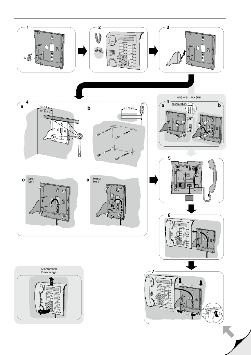
Zur Montage siehe auch Ausklappseite 3 (Pos. bis ).
1. Teilnehmeranschlussleitung vom optiPoint-Telefon abstecken.
2. Das Telefon mit dem Tastenfeld nach unten auf eine weiche Unterlage legen.
3. Das key module/BLF in die am Telefon bzw. am angebauten
optiPoint key module vorgesehenen Schnappvorrichtungen einhängen.
4. Verbinden Sie das optiPoint key module/BLF und das optiPoint-Telefon bzw.
optiPoint key module mit dem mitgelieferten Anschlusskabel .
5. Beschriftungsstreifen und Abdeckfolien am optiPoint key module/BLF einlegen.
6. Teilnehmeranschlussleitung am optiPoint-Telefon wieder anstecken.
Das optiPoint-Telefon und das optiPoint key module/BLF sind betriebsbereit.
9
Page 10

optiPoint signature module
optiPoint signature module
Das optiPoint signature module kann nur an der Kommunikationsplattform HiPath 4000 betrieben werden.
Sicherheitshinweise
Die optiPoint-Telefone und Beistellgeräte entsprechen den vorgeschriebenen
Konformitäts- und Sicherheitsbestimmungen (CE).
• Setzen Sie die Geräte keiner direkten Sonnenbestrahlung oder anderen Wärmequellen aus.
• Schützen Sie die Geräte vor Feuchtigkeit oder Eindringen von Flüssigkeiten.
• Führen Sie, außer der Chipkarte, keine Gegenstände in Geräteöffnungen ein.
• Verwenden Sie nur die Ihnen vom Systembetreuer zur Verfügung gestellten
Chipkarten.
Einsatzmöglichkeiten
Das optiPoint signature module ist an folgende Telefone anschließbar:
optiPoint 600 office, optiPoint 500 advance/standard/basic,
optiPoint 420 advance/standard, optiPoint 410 advance/standard,
optiPoint 400 standard.
Das optiPoint signature module ist ein Chipkartenleser, der die Nutzung der PINgeschützten Funktionen erleichtert.
Verpackungsinhalt
• 1 optiPoint signature module
• 1 Anschlusskabel
10
Montage
Zur Montage siehe auch Ausklappseite 3 (Pos. bis ).
1. Teilnehmeranschlussleitung vom optiPoint-Telefon abstecken.
2. Das Telefon mit dem Tastenfeld nach unten auf eine weiche Unterlage legen.
3. Das optiPoint signature module in die am Telefon bzw. am angebauten
optiPoint key module vorgesehenen Schnappvorrichtungen einhängen.
4. Verbinden Sie das optiPoint signature module und das optiPoint-Telefon bzw.
key module mit dem mitgelieferten Anschlusskabel .
5. Teilnehmeranschlussleitung am optiPoint-Telefon wieder anstecken.
Das optiPoint-Telefon und das optiPoint signature module sind betriebsbereit.
Page 11

optiPoint display module/optiPoint application module
optiPoint display module/
optiPoint application module
Sicherheitshinweise
Die optiPoint-Telefone und Beistellgeräte entsprechen den vorgeschriebenen
Konformitäts- und Sicherheitsbestimmungen (CE).
• Setzen Sie die Geräte keiner direkten Sonnenbestrahlung oder anderen Wärmequellen aus.
• Schützen Sie die Geräte vor Feuchtigkeit oder Eindringen von Flüssigkeiten.
• Führen Sie niemals Gegenstände in Geräteöffnungen ein.
Einsatzmöglichkeiten
Das optiPoint display module ist an folgende Telefone anschließbar:
optiPoint 410 advance/standard, optiPoint 420 advance/standard.
Das optiPoint application module ist an folgende Telefone anschließbar:
optiPoint 410 advance/standard, optiPoint 420 advance/standard,
optiPoint 500 basic/standard/advance.
Das optiPoint display module/optiPoint application module unterstützt Sie beim
Telefonieren und bietet viele zusätzliche, nützliche Funktionen mit seiner grafischen Oberfläche des Touch-Screen-Displays.
Verpackungsinhalt
• 1 optiPoint display module/optiPoint application module
• 1 Anschlusskabel
Montage
Zur Montage siehe auch Ausklappseite 3 (Pos. bis ).
1. Teilnehmeranschlussleitung vom optiPoint-Telefon abstecken.
2. Das Telefon mit dem Tastenfeld nach unten auf eine weiche Unterlage legen.
3. Das optiPoint display module/optiPoint application module in die am optiPoint-Telefon vorgesehenen Schnappvorrichtungen einhängen.
DeutschEnglishFrançaisNederlandsItalianoEspañolPortuguês
4. Verbinden Sie das optiPoint display module/optiPoint application module
und das optiPoint-Telefon mit dem mitgelieferten Anschlusskabel .
5. Teilnehmeranschlussleitung am optiPoint-Telefon wieder anstecken.
Das optiPoint-Telefon und das optiPoint display module/
optiPoint application module sind betriebsbereit.
11
Page 12

optiPoint self labelling key module
optiPoint self labelling key module
Sicherheitshinweise
Die optiPoint-Telefone und Beistellgeräte entsprechen den vorgeschriebenen
Konformitäts- und Sicherheitsbestimmungen (CE).
• Setzen Sie die Geräte keiner direkten Sonnenbestrahlung oder anderen Wärmequellen aus.
• Schützen Sie die Geräte vor Feuchtigkeit oder Eindringen von Flüssigkeiten.
• Führen Sie niemals Gegenstände in Geräteöffnungen ein.
Einsatzmöglichkeiten
Das optiPoint self labelling key module ist an folgende Telefone anschließbar:
optiPoint 410 advance/standard, optiPoint 420 advance/standard.
Mit dem optiPoint self labelling key module können 13 zusätzliche Funktions-/
Namentasten belegt werden.
Sie können an Ihrem optiPoint-Telefon, abhängig vom Typ der Telefonanlage
mehrere optiPoint self labelling key module betreiben (max. 2).
Verpackungsinhalt
• 1 optiPoint self labelling key module
• 1 Anschlusskabel
Montage
12
Zur Montage siehe auch Ausklappseite 3 (Pos. bis ).
1. Teilnehmeranschlussleitung vom optiPoint-Telefon abstecken.
2. Das Telefon mit dem Tastenfeld nach unten auf eine weiche Unterlage legen.
3. Das optiPoint self labelling key module in die am Telefon bzw. am angebauten optiPoint self labelling key module vorgesehenen Schnappvorrichtungen
einhängen.
4. Verbinden Sie das optiPoint self labelling key module und das optiPoint-Telefon bzw. optiPoint self labelling key module mit dem mitgelieferten Anschlusskabel .
5. Teilnehmeranschlussleitung am optiPoint-Telefon wieder anstecken.
Das optiPoint-Telefon und das optiPoint self labelling key module sind betriebsbereit.
Page 13
optiPoint acoustic adapter
S
*)
optiPoint acoustic adapter
Sicherheitshinweise
Die optiPoint-Telefone und Adapter entsprechen den vorgeschriebenen Konformitäts- und Sicherheitsbestimmungen (CE).
• Setzen Sie die Geräte keiner direkten Sonnenbestrahlung oder anderen Wärmequellen aus.
• Schützen Sie die Geräte vor Feuchtigkeit oder Eindringen von Flüssigkeiten.
• Führen Sie niemals Gegenstände in Geräteöffnungen ein.
Einsatzmöglichkeiten
Der acoustic adapter ist an folgende Telefone anschließbar:
optiPoint 600 office, optiPoint 500 advance/standard/basic,
optiPoint 420 advance/standard, optiPoint 410 advance/standard.
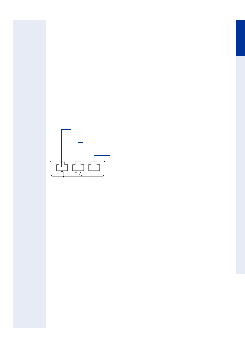
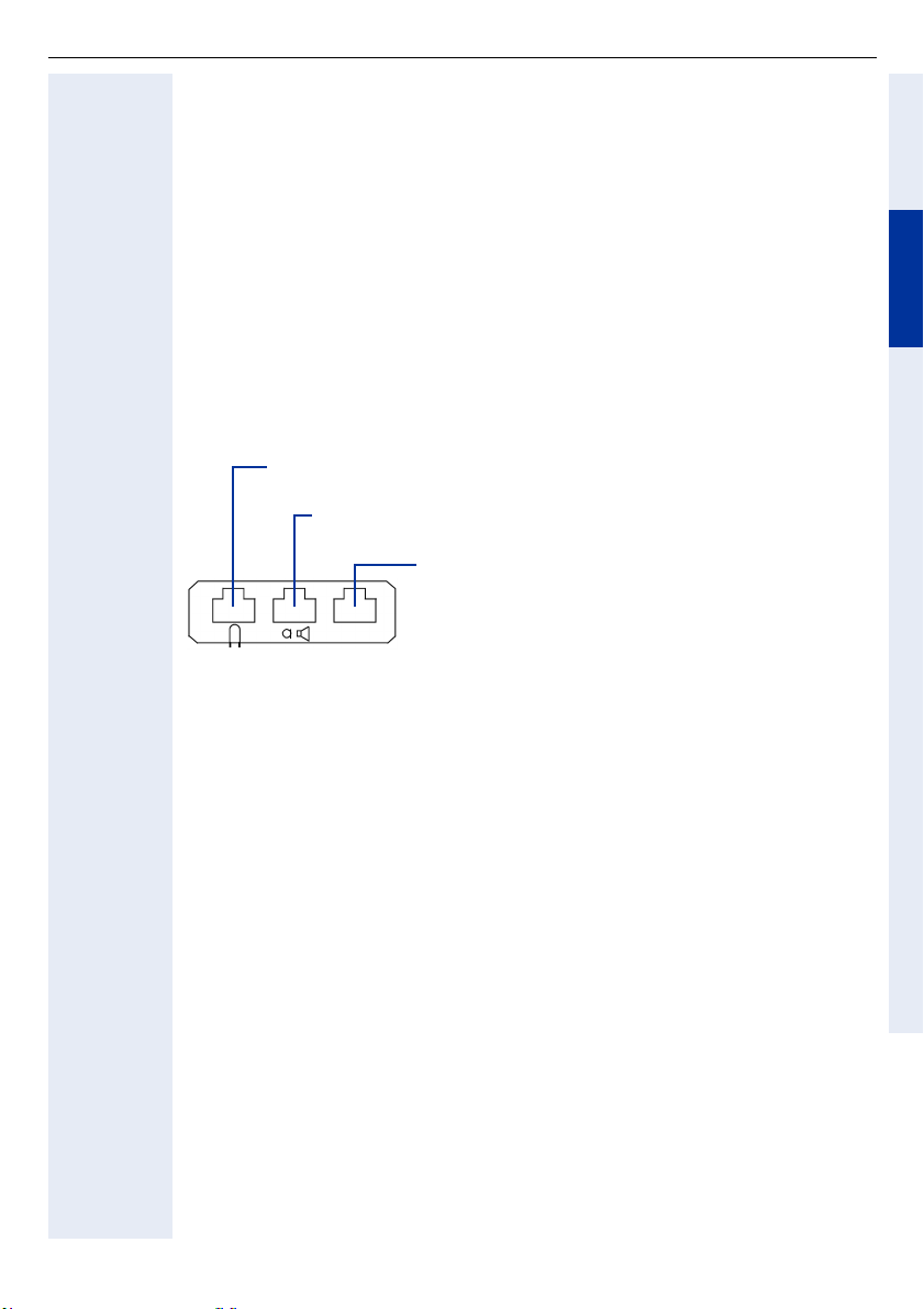
Der acoustic adapter verfügt über drei Anschlüsse für:
prechgarnitur (schnurgebunden 121TR9-5/schnurlos 121TR9-5
Anschluss an Miniwestern 8/8
aktive Lautsprecherbox und Elektret-Mikrofon
Anschluss an Miniwestern 8/8 über Y- K a b e l (L36453-Z5-C199)
2 Signalgeber, z. B. eine Zweitklingel (24 V AC/60 V
DC, 5 W) und eine Besetztlampe oder Türöffner
Anschluss an Miniwestern 6/6, galvanisch getrennt
DeutschEnglishFrançaisNederlandsItalianoEspañolPortuguês
Verpackungsinhalt
• 1 optiPoint acoustic adapter
Montage
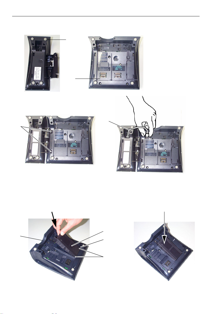
Zur Montage siehe auch Ausklappseite 3 (Pos. bis ).
1. Teilnehmeranschlussleitung vom optiPoint-Telefon abstecken.
2. Das Telefon mit dem Tastenfeld nach unten auf eine weiche Unterlage legen.
3. Den Adapter mit der Steckerleiste nach unten halten und mit den zwei
Rastnasen in die beiden Schlitze an einem der beiden Einbauplätze auf
der Unterseite des Telefons einhängen.
4. Den Adapter mit der Steckerleiste unter leichtem Druck bis zum Anschlag in
die Buchsenleiste drücken .
5. Über die drei Anschlüsse an der Rückseite des acoustic adapters können Sie
nun die Zusatzeinrichtungen anschließen (mit Symbolen gekennzeichnet).
6. Teilnehmeranschlussleitung am optiPoint-Telefon wieder anstecken.
Das optiPoint-Telefon mit dem Adapter ist betriebsbereit.
13
Page 14

optiPoint analog adapter
optiPoint analog adapter
Sicherheitshinweise
Die optiPoint-Telefone und Adapter entsprechen den vorgeschriebenen Konformitäts- und Sicherheitsbestimmungen (CE).
• Setzen Sie die Geräte keiner direkten Sonnenbestrahlung oder anderen Wärmequellen aus.
• Schützen Sie die Geräte vor Feuchtigkeit oder Eindringen von Flüssigkeiten.
• Führen Sie niemals Gegenstände in Geräteöffnungen ein.
Einsatzmöglichkeiten
Der analog adapter ist an folgende Telefone anschließbar:
optiPoint 600 office, optiPoint 500 advance/standard/basic.
Mit dem analog adapter haben Sie die Möglichkeit, ein zusätzliches Telefon, Faxgerät, Modem (z. B. PC mit integrierter Modemkarte) oder Anrufbeantworter
mit analoger Schnittstelle und MFV-Wahl anzuschließen.
Wird ein analog adapter an ein optiPoint-Telefon gesteckt und daran ein analoges
Telefon angeschlossen, so muss am optiPoint-Telefon ein Steckernetzgerät eingeschleift werden.
Je U
P0/E
Verpackungsinhalt
• 1 optiPoint analog adapter
-Teilnehmeranschluss ist nur ein analog adapter zulässig.
14
Montage
Zur Montage siehe auch Ausklappseite 3 (Pos. bis ).
1. Teilnehmeranschlussleitung vom optiPoint-Telefon abstecken.
2. Das Telefon mit dem Tastenfeld nach unten auf eine weiche Unterlage legen.
3. Den Adapter mit der Steckerleiste nach unten halten und mit den zwei
Rastnasen in die beiden Schlitze an einem der beiden Einbauplätze auf
der Unterseite des Telefons einhängen.
4. Den Adapter mit der Steckerleiste unter leichtem Druck bis zum Anschlag in
die Buchsenleiste drücken .
5. Über den 6-poligen Anschluss an der Rückseite des analog adapters können
Sie nun ein analoges Endgerät anschließen (a/b auf Pin 3 und 4).
6. Teilnehmeranschlussleitung am optiPoint-Telefon wieder anstecken.
Das optiPoint-Telefon mit dem Adapter ist betriebsbereit.
Page 15

optiPoint ISDN adapter
optiPoint ISDN adapter
Sicherheitshinweise
Die optiPoint-Telefone und Adapter entsprechen den vorgeschriebenen Konformitäts- und Sicherheitsbestimmungen (CE).
• Setzen Sie die Geräte keiner direkten Sonnenbestrahlung oder anderen Wärmequellen aus.
• Schützen Sie die Geräte vor Feuchtigkeit oder Eindringen von Flüssigkeiten.
• Führen Sie niemals Gegenstände in Geräteöffnungen ein.
Einsatzmöglichkeiten
Der ISDN adapter ist an folgende Telefone anschließbar:
optiPoint 600 office, optiPoint 500 advance/standard/basic.
Der ISDN adapter dient zur Bereitstellung des ISDN S
Endgeräte.
Die S0-Endgeräte müssen über eine eigene Speisung verfügen.
Der Anschluss befindet sich auf der Rückseite des Adapters.
Je U
-Teilnehmeranschluss ist nur ein ISDN adapter zulässig.
P0/E
Verpackungsinhalt
• 1 optiPoint ISDN adapter
-Basisanschlusses für S0-
0
DeutschEnglishFrançaisNederlandsItalianoEspañolPortuguês
Montage
Zur Montage siehe auch Ausklappseite 3 (Pos. bis ).
1. Teilnehmeranschlussleitung vom optiPoint-Telefon abstecken.
2. Das Telefon mit dem Tastenfeld nach unten auf eine weiche Unterlage legen.
3. Der Adapter wird an einem der beiden Einbauplätze auf der Unterseite des
Telefons eingebaut. Dazu die beiden Nasen des Adapters in die beiden
Schlitze des Telefons schieben.
4. Den Adapter in Pfeilrichtung unter leichtem Druck bis zum Anschlag nach
unten drücken.
5. An den ISDN Adapter können bis zu zwei ISDN-Endgeräte an einem bis zu
150 m langen S
sen werden. Die ISDN-Geräte können jedoch nicht gleichzeitig betrieben
werden, da nur ein B-Kanal zur Verfügung steht.
6. Teilnehmeranschlussleitung am optiPoint-Telefon wieder anstecken.
Das optiPoint-Telefon mit dem Adapter ist betriebsbereit.
-Bus mit zwei 100 Abschlusswiderständen angeschlos-
0
Ω
15
Page 16

optiPoint phone adapter
optiPoint phone adapter
Sicherheitshinweise
Die optiPoint-Telefone und Adapter entsprechen den vorgeschriebenen Konformitäts- und Sicherheitsbestimmungen (CE).
• Setzen Sie die Geräte keiner direkten Sonnenbestrahlung oder anderen Wärmequellen aus.
• Schützen Sie die Geräte vor Feuchtigkeit oder Eindringen von Flüssigkeiten.
• Führen Sie niemals Gegenstände in Geräteöffnungen ein.
Einsatzmöglichkeiten
Der phone adapter ist an folgende Telefone anschließbar:
optiPoint 600 office, optiPoint 500 advance/standard/basic.
Mit dem phone adapter haben Sie die Möglichkeit, ohne Verwendung eines Spezialkabels ein zweites optiPoint-Telefon anzuschließen.
Der Anschluss befindet sich auf der Rückseite des Adapters.
Je U
Verpackungsinhalt
• 1 optiPoint phone adapter
Montage
-Teilnehmeranschluss ist nur ein phone adapter zulässig.
P0/E
16
Zur Montage siehe auch Ausklappseite 3 (Pos. bis ).
1. Teilnehmeranschlussleitung vom optiPoint-Telefon abstecken.
2. Das Telefon mit dem Tastenfeld nach unten auf eine weiche Unterlage legen.
3. Den Adapter mit der Steckerleiste nach unten halten und mit den zwei
Rastnasen in die beiden Schlitze an einem der beiden Einbauplätze auf
der Unterseite des Telefons einhängen.
4. Den Adapter mit der Steckerleiste unter leichtem Druck bis zum Anschlag in
die Buchsenleiste drücken .
5. Über den 6-polige Buchse an der Rückseite des phone adapters können Sie
nun ein zweites optiPoint-Telefon anschließen.
6. Teilnehmeranschlussleitung am optiPoint-Telefon wieder anstecken.
Das optiPoint-Telefon mit dem Adapter ist betriebsbereit.
Page 17
optiPoint recorder adapter
optiPoint recorder adapter
Sicherheitshinweise
Die optiPoint-Telefone und Adapter entsprechen den vorgeschriebenen Konformitäts- und Sicherheitsbestimmungen (CE).
• Setzen Sie die Geräte keiner direkten Sonnenbestrahlung oder anderen Wärmequellen aus.
• Schützen Sie die Geräte vor Feuchtigkeit oder Eindringen von Flüssigkeiten.
• Führen Sie niemals Gegenstände in Geräteöffnungen ein.
Einsatzmöglichkeiten
Der recorder adapter ist an folgende Telefone anschließbar:
optiPoint 600 office, optiPoint 500 advance/standard/basic,
optiPoint 420 advance/standard, optiPoint 410 advance/standard.
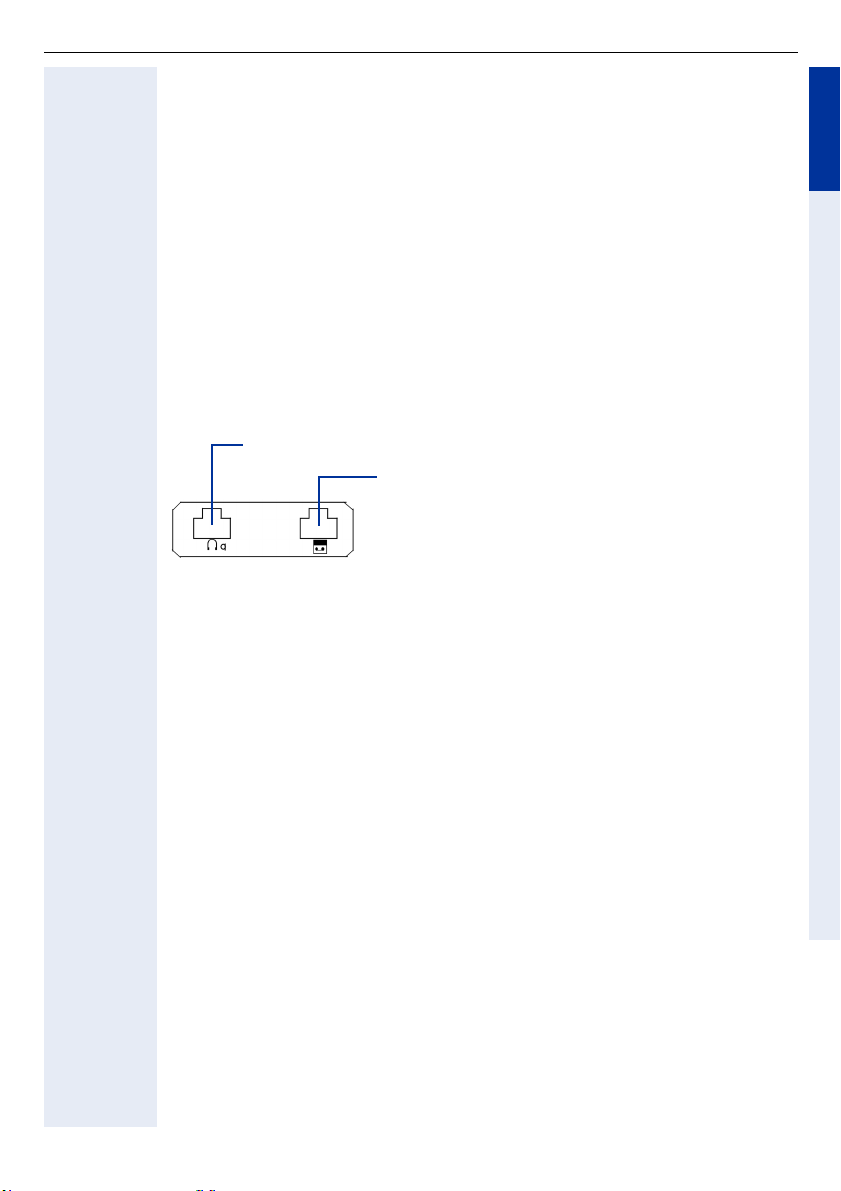
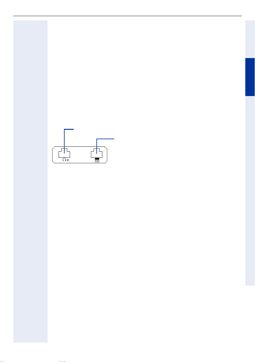
Der recorder adapter verfügt über Anschlüsse für:
Zweithörer an 4-poliger RJ11-Buchse
Aufzeichnungsgerät (Recorder)
an 6-poliger RJ11-Buchse
Verpackungsinhalt
• 1 optiPoint recorder adapter
DeutschEnglishFrançaisNederlandsItalianoEspañolPortuguês
Montage
Zur Montage siehe auch Ausklappseite 3 (Pos. bis ).
1. Teilnehmeranschlussleitung vom optiPoint-Telefon abstecken.
2. Das Telefon mit dem Tastenfeld nach unten auf eine weiche Unterlage legen.
3. Der Adapter wird an einem der beiden Einbauplätze auf der Unterseite des
Telefons eingebaut. Dazu die beiden Nasen des Adapters in die beiden
Schlitze des Telefons schieben.
4. Den Adapter in Pfeilrichtung unter leichtem Druck bis zum Anschlag nach
unten drücken.
5. Den Zweithörer und das Aufzeichnungsgerät an die entsprechend gekennzeichneten Adapterbuchse(n) anschließen.
6. Teilnehmeranschlussleitung am optiPoint-Telefon wieder anstecken.
Das optiPoint-Telefon mit dem Adapter ist betriebsbereit.
17
Page 18

D
eutsc
h
Zubehör
Aktive Lautsprecherbox
Aktive Lautsprecherbox
Sicherheitshinweise
• Setzen Sie die Geräte keiner direkten Sonnenbestrahlung oder anderen Wärmequellen aus.
• Schützen Sie die Geräte vor Feuchtigkeit oder Eindringen von Flüssigkeiten.
• Führen Sie niemals Gegenstände in Geräteöffnungen ein.
Einsatzmöglichkeiten
Die aktive Lautsprecherbox kann einzeln oder gemeinsam mit dem Beistellmikrofon über optipoint acoustic adapter (S30817-K7110-B508) und Y-Kabel
(L36453-Z5-C199) an folgende Telefone angeschlossen werden:
optiPoint 600 office, optiPoint 500 advance/standard/basic,
optiPoint 420 advance/standard, optiPoint 410 advance/standard.
Allgemeines
Die aktive Lautsprecherbox verbessert die Sprachqualität beim Lauthören.
Durch das Anschließen der Lautsprecherbox wird der interne Lautsprecher des
Telefons ausgeschaltet. Wenn Sie die Taste „Lautsprecher“ am Telefon drücken, erfolgt Lauthören nur über die Lautsprecherbox.
Die Lautsprecherbox ist freistehend aufstellbar oder kann z. B. mit einem Winkel
an der Wand montiert werden.
Lieferumfang
• 1 Aktive Lautsprecherbox mit Anschlusskabel (2 m).
• 1 Steckernetzgerät 230 V AC/22 V AC mit Anschlusskabel (2 m).
• 1 Kunststoffeinsatz und 1 Befestigungsschraube für Wandmontage.
• 1 Montageananleitung.
18
Page 19

Aktive Lautsprecherbox
Inbetriebnahme
Achtung!
Nur mitgeliefertes Steckernetzgerät verwenden!
Voraussetzung: Der entspechende Adapter ist bereits vorschriftsmäßig ins Telefon eingebaut.
1. Drehknopf an der Vorderseite der Lautsprecherbox bis zum linken Anschlag
drehen (geringste Lautstärke).
2. Miniwestern-Stecker 8/8 des Y-Kabel in die Anschlussbuchse des acoustic
adapters stecken.
3. Stecker des Anschlusskabels in die Anschlussbuchse des Y-Kabels stecken.
4. Winkelstecker des mitgelieferten Steckernetzgerätes in die runde Buch-
se am Boden der Lautsprecherbox stecken.
5. Lautsprecherbox nicht in Richtung Telefon oder Beistellmikrofon aufstel-
len, um akustische Rückkopplungen zu vermeiden.
6. Steckernetzgerät in die 230-V-Steckdose stecken.
Die Betriebsbereitschafts-Anzeige (LED) an der Vorderseite der Lautspre-
cherbox leuchtet.
7. Grundlautstärke einstellen:
Über den Drehknopf der Lautsprecherbox wird lediglich die Grundlautstärke
eingestellt, die den Gegebenheiten des Raumes angepasst und dann nicht
mehr verändert werden sollte.
Einstellvorgang:
• Lautstärke des Telefon-Lautsprechers auf leiseste Stufe einstellen und
speichern, siehe Telefonanleitung.
• Mit Taste „Lautsprecher“ Lauthören einschalten.
• Beispielsweise mittels Wählton oder während eines Gesprächs die Grundlautstärke (normale Lautstärke) mit dem Drehknopf der Lautsprecherbox einstellen.
DeutschEnglishFrançaisNederlandsItalianoEspañolPortuguês
Bedienung
Die Funktion Lauthören schalten Sie mit Taste „Lautsprecher“ des Telefons ein
und aus. Die aktuelle Lautstärke der Lautsprecherbox sollen Sie gegebenenfalls
nur über die Tasten „+“ und „–“ des Telefons verändern.
19
Page 20

Aktive Lautsprecherbox
Wandmontage
1. Entfernen Sie von der Unterseite der Lautsprecherbox den hinteren Fuß
(Noppen).
2. Drücken Sie den mitgelieferten Kunststoffeinsatz in die Öffnung.
3. Mit dem Kunststoffeinsatz und der mitgelieferten Schraube kann die Laut-
sprecherbox z. B. auf einem Montagewinkel (nicht im Lieferumfang!) stehend befestigt werden.
Hinweis: Kunststoffeinsatz und Schraube sind für direkte (hängende) Wandmontage nicht geeignet!
Technische Daten
Stromversorgung: Nur über mitgeliefertes Steckernetzgerät:
Verstärkerleistung: 7 Watt
Frequenzbereich: 100 Hz–16 kHz
Eingangsempfindlichkeit: 250 mV (bei Vollaussteuerung)
Impedanz: 10 k
Anschlusskabel: 2 m; mit Miniwestern-Stecker 4/4
Abmessungen: 160 x 98 x 95 (H x B x T, in mm)
Gewicht: etwa 500 g
L30460-X1325-X; für GB:L30460-X1325-X1
230 V AC +6%/–10% / 22 V AC; 50 Hz;
Anschlusskabel 2 m; mit Winkelstecker
Ω
20
Page 21

Beistellmikrofon
Beistellmikrofon
Sicherheitshinweise
• Setzen Sie die Geräte keiner direkten Sonnenbestrahlung oder anderen Wärmequellen aus.
• Schützen Sie die Geräte vor Feuchtigkeit oder Eindringen von Flüssigkeiten.
• Führen Sie niemals Gegenstände in Geräteöffnungen ein.
Einsatzmöglichkeiten
Das Beistellmikrofon kann einzeln oder gemeinsam mit der aktiven Lautsprecherbox über optipoint acoustic adapter (S30817-K7110-B508) und Y-Kabel
(L36453-Z5-C199) an folgende Telefone angeschlossen werden:
optiPoint 600 office, optiPoint 500 advance/standard/basic,
optiPoint 420 advance/standard, optiPoint 410 advance/standard.
Allgemeines
Das Beistellmikrofon verbessert die Sprachqualität beim Freisprechen, z. B. an
einem Besprechungstisch. Durch das Anschließen des Beistellmikrofons wird
das interne Mikrofon des Telefons ausgeschaltet. Wenn Sie die Taste „Lautsprecher“ am Telefon drücken, erfolgt Freisprechen nur über das Beistellmikrofon. Das Mikrofon ist freistehend aufstellbar. Der optimale Sprechabstand beträgt 50 cm.
Lieferumfang
• 1 Beistellmikrofon mit Anschlusskabel (2 m)
• 1 Montageanleitung
DeutschEnglishFrançaisNederlandsItalianoEspañolPortuguês
Inbetriebnahme
1. Miniwestern-Stecker 8/8 des Y-Kabel in die Anschlussbuchse des acoustic
adapters stecken.
2. Stecker des Anschlusskabels in die Anschlussbuchse des Y-Kabels stecken.
3. Beistellmikrofon nicht in Richtung Telefon oder Lautsprecherbox aufstel-
len, um akustische Rückkopplungen zu vermeiden.
21
Page 22

Beistellmikrofon
Bedienung
Die Funktion Freisprechen wird über die Taste „Lautsprecher“ des Telefons einund ausgeschaltet. Die Zustands-Anzeige (LED) an der Oberseite des Mikrofons
leuchtet im Ein-Zustand – Mikrofon aktiv.
Durch Drücken der Stummtaste (Mute-Taste)kann das Mikrofon gegebenenfalls
zeitweise ausgeschaltet werden – Anzeige dunkel, z. B. bei Rückfragen im
Raum. Nach Loslassen der Stummtaste ist das Mikrofon wieder aktiv.
Technische Daten
Akustische Arbeitsweise: Druckempfänger
Frequenzbereich: 100 Hz–7 kHz
Charakteristik: Niere
Ausgangsimpedanz: 10 k
Versorgungsspannung: 3,8 V–6 V DC;
Stromaufnahme: max. 6 mA bei 3,8 V und LED ein
Anschlusskabel: 2 m; mit Miniwestern-Stecker 4/4
Abmessungen: 25 x 68 x 77 (H x B x T, in mm)
Ω
Speisung vom Adapter über Anschlusskabel
22
Page 23

optiPoint Conference Kit
optiPoint Conference Kit
Allgemeines
Das optiPoint Conference Kit verbessert die Freisprechqualität bei Telefonkonferenzen, insbesondere in Konferenzräumen mit verteilt sitzenden Gesprächsteilnehmern. In der Maximalkonfiguration können bis zu 2 Konferenz-Lautsprecherboxen und 8 Konferenz-Mikrofone
Raumabdeckung angeschlossen werden. Die Konferenz-Mikrofone verfügen
hierbei über jeweils eine eigene Verstärker- und Steuerelektronik die bewirkt,
dass nur gerade besprochene Mikrofone aktiv sind, um somit Störpegel (Raumecho) vom Nutzsignal weitgehend zu trennen.
Sowohl die Ansprechempfindlichkeit der Mikrofone als auch ein Raumhintergrundpegel ist an den Verteiler-Modulen entsprechend der vorhandenen Raumakustik einstellbar.
Bei Gesprächspausen und somit abgeschalteten Mikrofonen kann bei zugeschalteten Gesprächsteilnehmern somit nicht der Eindruck entstehen, dass er
getrennt worden ist.
Jedes Mikrofon verfügt über eine Mutetaste, das bei Betätigung alle KonferenzMikrofone stumm schaltet.
Die Stromversorgung des optiPoint Conference Kit erfolgt über ein eigenes
Netzgerät.
Sicherheitshinweise
• Setzen Sie die Geräte keiner direkten Sonnenbestrahlung oder anderen Wärmequellen aus!
• Schützen Sie die Geräte vor Feuchtigkeit oder Eindringen von Flüssigkeiten!
• Führen Sie niemals Gegenstände in Geräteöffnungen ein!
1
zur optimalen akustischen
DeutschEnglishFrançaisNederlandsItalianoEspañolPortuguês
[1] Zusätzlich ist der Einsatz eines Funk-Mikrofons möglich.
Anfragen richten Sie an: [email protected]
23
Page 24
optiPoint Conference Kit
Einsatzmöglichkeiten
Das optiPoint Conference Kit Basic und Extension wird als Ergänzungseinrichtung an optiPoint Telefone mit optiPoint acoustic adapter (S30817-K7110-B508)
angeschlossen.
Für das optiPoint Conference Kit Basic und Extension sind ausschließlich die
im Lieferumfang enthaltenen oder als Erweiterung bestellbaren Konferenz
Lautsprecherboxen und Konferenz Mikrofone zulässig. Diese sind eigens
für das optiPoint Conference Kit konzipiert.
Montage/Inbetriebnahme
Voraussetzung: Der optiPoint acoustic adapter ist bereits vorschriftsmäßig im
vorhandenen optiPoint Telefon eingebaut.
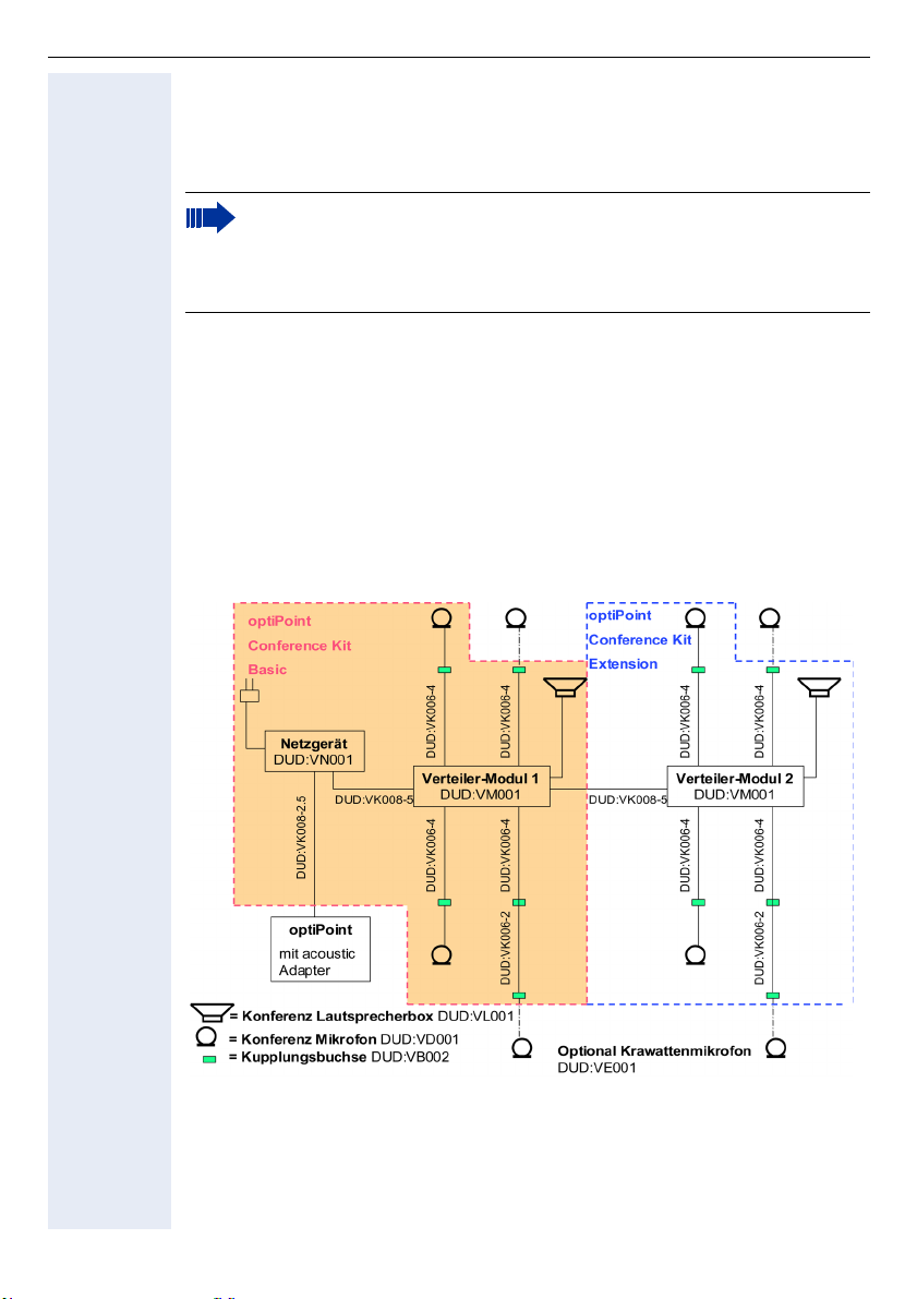
Nachstehende Abbildung zeigt den Anschluss der einzelnen Komponenten miteinander.
Achtung: Das Y-Kabel (L36453-Z5-C199) für Direktanschluss von Aktiver
Lautsprecherbox (L30460-X1278-X) und Beistellmikrofon
(L30460-X1279-X) wird hierzu nicht benötigt. Die vorgenannten Aktiven
Lautsprecherboxen und Beistellmikrofone zum Direktanschluss können
nicht am optiPoint Conference Kit verwendet werden.
24
Page 25

optiPoint Conference Kit
Montage
Zur Grundausstattung optiPoint Conference Kit Basic gehört ein Netzgerät, ein
Verteiler-Modul, eine Konferenz Lautsprecherbox, zwei Konferenz Mikrofone
sowie Kabel und entsprechendes Montagematerial (siehe Lieferumfang). Das
Montagematerial-Set enthält auch die Anschlusskabel für 2 weitere optionale
Mikrofone (wahlweise auch als Krawattenmikrofon lieferbar), sowie zwei zusätzliche Anschlusskabel und Kupplungsbuchsen, falls die Mikrofonanschlüsse verlängert werden müssen.
Mit Ausnahme des Netzgeräts und Anschlusskabel zum optiPoint acoustic Adapter gehören zum optiPoint Conference Kit Extension die gleichen Komponenten.
Das Anschlusskabel „DUD:VK008-2,5“ vom optiPoint acoustic Adapter (Symbol
für Lautsprecher/Mikro) zum Netzgerät ist mit kodierten Steckern versehen und
darf nur für die Verbindung FS.-Netzgerät verwendet werden (rot gekennzeichnet).
Achtung: Es darf auf keinen Fall mit der Ausgangsbuchse des Netzgerätes zum Verteiler-Modul verbunden werden. Für die Verbindung Netzgerät zum Verteiler-Modul bzw. Verteiler-Modul 1 mit Verteiler-Modul 2 ist
das 5 Meter-Kabel „DUD:VK008-5“ zu verwenden.
Zum optisch verborgenen Aufbau der Anlage besitzen Verteiler-Module und
Netzgerät seitliche Befestigungslaschen, durch die eine Befestigung unterhalb
des Tisches möglich ist, falls kein Doppelboden vorhanden ist. Die im Montagematerial-Set befindlichen, mit Montagelöchern versehenen Anschlussbuchsen
6/4 sind für den Anschluss der Konferenz-Mikrofone vorgesehen. Die Buchsen
sind sinnvoll in der Nähe der Sitzposition der Gesprächsteilnehmer unterhalb der
Tischkante anzubringen, die einerseits das Anschlusskabel „DUD:VK006-4“ mit
dem Verteiler-Modul, anderseits das Mikrofon verbinden.
Die Anschlusskabel „DUD:VK006-4“ (Verteiler-Modul zur Kupplungsbuchse)
können falls erforderlich durch die in den Sets befindlichen Zusatzkabel
„DUD:VK006-2“ und zusätzlichen Kupplungsbuchsen verlängert werden.
DeutschEnglishFrançaisNederlandsItalianoEspañolPortuguês
Achtung: Es dürfen nur die im Set befindlichen Kabel verwendet werden.
Die Konferenz-Lautsprecherbox wird mit der gekennzeichneten Buchse im Verteiler-Modul verbunden. Ein zusätzliches Netzgerät für den Aktivlautsprecher ist
nicht erforderlich, da die Stromversorgung durch das Modulnetzgerät erfolgt.
Die mitgelieferten, mit Klebeflächen versehenen Kabelklemmen dienen zur Befestigung der Zuleitungen unterhalb der Tischplatten. Durch die Verkabelung aller Bauteile miteinander über Steckverbindungen ist die Anlage variabel einsetzbar und kann z. B. bei Umgruppierung von Konferenztischen problemlos und
ohne großem Zeitaufwand den Gegebenheiten angepasst werden.
Nach kompletter Installation wird das Netzgerät mit dem Stomnetz verbunden
(Länderspezifische Steckdosenadapter sind lokal bereitzustellen).
Die Betriebsanzeige (LED) an Lautsprecherbox und Mikrofonen leuchtet.
25
Page 26

optiPoint Conference Kit
Einstellungen
Um störenden akustischen Einfluss (Rückkoppeleffekt) des Lautsprechers auf
die Mikrofone zu vermeiden, sollte die Lautsprecherbox nicht in unmittelbare
Nähe und in direkter Ausrichtung eines Mikrofons positioniert werden.
Über den Drehknopf der Lautsprecherbox wird lediglich die Grundlautstärke eingestellt, die den Gegebenheiten des Raumes angepasst und dann nicht mehr
verändert werden sollte.
Vor Justierung dieser Grundlautstärke wählen Sie eine sehr leise Stufe des Telefonlautsprechers und speichern diese (siehe Bedienungsanleitung optiPoint).
Nach Drücken der Taste „Lautsprecher“ am Telefon kann mittels Wählton oder
eines Gesprächs die Grundlautstärke am Lautsprecherbox-Drehknopf vorgenommen werden.
Bei Einsatz der Extension-Konferenz Lautsprecherbox wählen Sie eine identische Grundlautstärke.
Spätere Lautstärke-Anpassungen während der Konferenzen sollten nur noch
über die Tasten u und v des optiPoint Telefons erfolgen.
Über den auf der Stirnseite der Verteiler-Module befindlichen Regler "Micro
sens." wird die Ansprechempfindlichkeit (Schwellwert) der Konferenz Mikrofone
eingestellt.
Die 4 LED's sind den Mikrofonen zugeordnet und dienen zur Kontrolle der Einstellung.
Bei optimaler Einstellung sollte nur die LED des gerade direkt besprochenen Mikrofones aufleuchten und bei Gesprächspausen alle Mikrofone abschalten. Damit bei zugeschaltenen Konferenzteilnehmern deswegen nicht der Eindruck entsteht, dass die Verbindung unterbrochen wurde, besteht die Möglichkeit einen
Restwert des Raumgeräusches als Hintergrundgeräusch einzublenden. Dies erfolgt über den Regler "Room noise" auf der Stirnseite der Verteilermodule. Alle
Einstellungen sollten den akustischen räumlichen Verhältnissen durch ein paar
Gesprächsversuche angepasst werden. Die optimalen Einstellwerte sollten an
beiden Verteiler-Modulen identisch gewählt werden.
26
Das optiPoint Conference Kit in Verbindung mit der Vollduplex-fähigen
Freisprecheinrichtung der optiPoint-Telefone benötigt zu Beginn einer
Konferenz, sowie bei plötzlichen Veränderungen der Raumakustik immer
einige Sekunden die Übertragungsqualität den neuen Bedingungen optimal anzupassen. Dies kann technisch bedingt nur gelingen, wenn während dieser Phasen möglichst nur ein Konferenzteilnehmer spricht. In den
Menüeinstellungen des optiPoint-Freisprechens (siehe Bedienungsanleitung optiPoint) finden Sie eine weitere Optimierungsmöglichkeit, die
Freisprechqualität einer gedämpften, normalen oder halligen Raumakustik anzupassen.
Page 27

optiPoint Conference Kit
Technische Daten
Netzgerät primär: 230V AC, 30 VA
Sekundär:24 V DC stabilisiert
5 V DC stabilisiert
Stromaufnahme: 60mA primär
Material: PS (Polystorol)
Schutzart: IP 40
Abmessungen: 150 x 80 x 55 (L x B x H in mm)
Verteiler-Modul 4 Konferenz-Mikrofoneingänge mit jeweils nachgeschaltetem Ver-
Konferenz-Lautsprecher Verstärkerleistung: 7 Watt
Konferenz-Mikrofon Akustische Arbeitsweise: Druckempfänger
Konferenz-Krawattenmikrofon
stärker und separater Tonpegelbezogener Abschaltautomatik
Mute-Abschaltelektronik für alle Kanäle
1 Lautsprecherboxanschluss mit Stromversorgung
Ausgangsbuchse für 2. Verteiler-Modul oder Funkmikrofon
Einstellregler für Ansprechempfindlichkeit der Mikrofone
Einstellregler für Raumhintergrundpegel
Frequenzbereich: 100 Hz-16 kHz
NF-Eingangsimpedanz: 10 K
Stromaufnahme: 30/170mA (Ruhe/Last)
Anschlusskabel: 2 m mit Miniwestern-Stecker
Abmessungen: 160 x 98 x 95 (H x B x T in mm)
Farbe: mangan
Gewicht: etwa 450 g
Frequenzbereich: 100 Hz - 7 kH
Charakteristik: Niere
Ausgangsimpedanz: 10 K
Versorgungsspannung: 5 V DC
Stromaufnahme: 6 mA
Anschlusskabel: 0,80 m
Abmessungen: 25 x 68 x 77 (H x B x T in mm)
Farbe: mangan
Akustische Arbeitsweise: Druckempfänger
Frequenzbereich: 100 Hz - 7 kHz
Charakteristik: Niere
Ausgangsimpedanz: 10 K
Versorgungsspannung: 5 V DC
Stromaufnahme: 4 mA
Anschlusskabel: 1,40 m
Abmessungen Gehäuse: 65 x 46 x 16 mm
Mikrofonteil: 20 x 13 mm
Ω
Ω
Ω
DeutschEnglishFrançaisNederlandsItalianoEspañolPortuguês
27
Page 28

optiPoint Conference Kit
Angabe zu CE
Achtung:
Lautsprecher und Konferenz-Mikrofon nur mit optiPoint Conference Kit
verwenden.
Vor Inbetriebnahme den Powerschalter des Krawattenmikrofons auf
"ON" stellen.
This equipment complies with the requirements of the EU directives 99/5/EEC:
EN 60950: 2000 Safety
EN 55022: 1998 Class B EMC, Emission ITE Residential
Environment
EN 55024: 1998 EMC, Immunity ITE Residential
Environment
28
Page 29

optiPoint Conference Kit
Lieferumfang zu den Bestellpositionen
optiPoint Conference Kit Basic (L30250-F600-A605)
Zum Anschluss an optiPoint acoustic adapter für 1 Konferenz-Lautsprecherbox/
max. 4 Konferenz-Mikrofone:
Lieferumfang Bestellnummer
1 Konferenz-Lautsprecherbox mangan, mit Anschlusskabel 2 m DUD:VL001
2 Konferenz-Mikrofone mangan, mit Anschlusskabel 0,8 m DUD:VD001
1 Netzgerät 230V AC; 24V+5V DC für max. 2 Lautsprecher/8 Mikrofone DUD:VN001
1 Verteiler-Modul mit
– 1 Eingang vom Netzgerät
– 1 Ausgang zum optiPoint Conferenz Kit Extension
– max. 4 Ausgänge zu Konferenz-Mikrofonen
– 1 Ausgang zur Konferenz-Lautsprecherbox
1 Anschlusskabel Netzgerät- optiPoint acoustic Adapter 2,5 m DUD:VK008-2.5
1 Anschlusskabel Netzgerät- Verteiler-Modul 5m DUD:VK008-5
1 Montagematerial Set
– 4 Anschlusskabel Verteiler-Modul - Konferenz-Mikrofon 4 m
– 2 Verlängerungskabel zum Konferenz Mikrofon 2 m
– 6 Kupplungsbuchsen für Mikrofone bzw. Kabelverlängerung
DUD:VM001
DUD:VZ001
optiPoint Conference Kit Extension (L30250-F600-A606)
Zur Erweiterung um 1 Konferenz-Lautsprecherbox und max. 4 Konferenz-Mikrofone:
Lieferumfang Bestellnummer
1 Konferenz-Lautsprecherbox mangan, mit Anschlusskabel 2 m DUD:VL001
2 Konferenz-Mikrofone mangan, mit Anschlusskabel 0,8 m DUD:VD001
1 Verteiler-Modul mit
– 1 Eingang vom Verteiler-Modul Basic
– max. 4 Ausgänge zu Konferenz-Mikrofonen
– 1 Ausgang zur Konferenz-Lautsprecherbox
1 Anschlusskabel Verteiler-Modul/ Verteiler-Modul 5 m DUD:VK008-5
1 Montagematerial Set
– 4 Anschlusskabel Verteiler-Modul - Konferenz-Mikrofon 4 m
– 2 Verlängerungskabel zum Konferenz Mikrofon 2 m
– 6 Kupplungsbuchsen für Mikrofone bzw. Kabelverlängerung
DUD:VM001
DUD:VZ001
DeutschEnglishFrançaisNederlandsItalianoEspañolPortuguês
Zum jeweiligen Vollausbau des optiPoint Conference Kit Basic oder Extension
mit 4 Mikrofonen stehen wahlweise zur Verfügung:
29
Page 30

optiPoint Conference Kit
Konferenz-Mikrofon (L30250-F600-A607)
Zur Erweiterung auf jeweils (pro Basic/Extension) max. 4 Konferenz-Mikrofone:
Lieferumfang Bestellnummer
1 Konferenz-Mikrofon (mangan) DUD:VD001
Konferenz-Krawattenmikrofon (L30250-F600-A608)
Zur Erweiterung auf jeweils (pro Basic/Extension) max. 4 Konferenz-Mikrofone:
Lieferumfang Bestellnummer
1 Konferenz-Krawattenmikrofon DUD:VE001
30
Page 31

USB-Tastatur
USB-Tastatur
Sicherheitshinweise
• Setzen Sie die Geräte keiner direkten Sonnenbestrahlung oder anderen Wärmequellen aus.
• Schützen Sie die Geräte vor Feuchtigkeit oder Eindringen von Flüssigkeiten.
• Führen Sie niemals Gegenstände in Geräteöffnungen ein.
Einsatzmöglichkeiten
Die USB-Tastatur ist an folgende Telefone anschließbar:
optiPoint 410 advance, optiPoint 420 advance, optiPoint 600 office.
Mit der USB-Tastatur haben Sie die Möglichkeit, Telefonbucheinträge, Tastenbeschriftungstexte (nur optiPoint 420 advance) und Parameter zum Einrichten
Ihres optiPoint-Telefons komfortabel einzugeben.
Inbetriebnahme
1. Teilnehmeranschlussleitung vom optiPoint-Telefon abstecken.
2. Das optiPoint mit dem Tastenfeld nach unten auf eine weiche Unterlage legen.
DeutschEnglishFrançaisNederlandsItalianoEspañolPortuguês
Die USB-Schnittstelle (USB-Master) befindet
sich seitlich im rechten, unteren Bereich der
Bodenwanne.
3. Stecker des USB-Kabels der Tastatur in die USB-Schnittstelle stecken.
Stecker mit Kabel der USB-Tastatur.
4. Teilnehmeranschlussleitung am optiPoint-Telefon wieder anstecken.
Die USB-Tastatur ist betriebsbereit.
31
Page 32
Wandhalterung
Wandhalterung
Sicherheitshinweise
Um ein problemloses Funktionieren und einen zuverlässigen Betrieb zu gewährleisten, müssen einige Faktoren bei der Planung der Systeminstallation berücksichtigt werden.
• Das Telefon muss zentral angeordnet werden, wobei besonders auf die erforderlichen Kabellängen zu achten ist;
• der für den Betrieb max. zulässige Temperaturbereich liegt zwischen +5 °C
und +40 °C, wobei die rel. Luftfeuchtigkeit 95% nicht überschreiten darf;
• das Gerät ist vor hoher Feuchtigkeit, entflammbaren Materialien, übermäßigem Staub, Vibrationen und mechanischer Beanspruchung zu schützen;
• das System sollte nicht an Orten mit direkter Sonneneinstrahlung, Staub,
Luftfeuchtigkeit, großer Hitze oder extremer Kälte und nicht in unmittelbarer
Nähe von elektrischen Kabeln montiert werden;
• die Nähe von Datenübertragungseinrichtungen, elektrischen Lötstationen,
Kopiergeräten, PCs und anderen elektrischen Geräten, die elektrische Störfelder erzeugen, ist zu meiden;
• das Gerät darf nicht in einem Schaltschrank montiert werden.
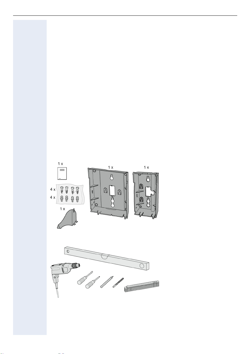
Verpackungsinhalt
32
oderTyp 1 Typ 2
Benötigtes Werkzeug
Montage
Zur Montage siehe Ausklappseite 2.
Page 33

English
Add-on Devi
c
optiPoint key module/optiPoint BLF
optiPoint key module/optiPoint BLF
optiPoint BLF cannot be operated on the HiPath 4000 communication
platform.
DeutschEnglishFrançaisNederlandsItalianoEspañolPortuguês
Safety Notes
The optiPoint telephones and add-on devices comply with the stipulated conformity and safety regulations (CE).
• Avoid exposing the equipment to direct sunlight or other sources of heat.
• Protect the equipment from moisture and liquids.
• Never insert objects into openings in the equipment.
Applications
The key module/BLF can be connected to the following telephones:
optiPoint 600 office, optiPoint 500 advance/standard/basic,
optiPoint 420 advance/standard, optiPoint 410 advance/standard,
optiPoint 400 standard.
The key module/BLF enables you to assign functions to 16/90 additional function/name keys.
You can operate up to two key modules on your optiPoint, regardless of the type
of telephone system.
A plug-type AC adapter may be required, depending on the configuration.
Package Contents
• 1 optiPoint key module/optiPoint BLF
• 1 connecting cable
Installation
For installation, see fold-out page 3 (Pos. to ).
1. Disconnect the subscriber line from the optiPoint telephone.
2. Place the telephone on a soft surface with the keypad facing down.
3. Mount the key module/BLF by snapping it into the slots on the telephone or on the installed key module.
4. Connect the key module/BLF and the optiPoint telephone or the key module
with the supplied connecting cable .
5. Attach the label sheets and the clear plastic cover to the key module/BLF.
6. Reconnect the subscriber line to the optiPoint telephone.
The optiPoint telephone and the optiPoint key module/BLF are ready for operation.
33
Page 34

optiPoint signature module
optiPoint signature module
The optiPoint signature module can only be operated on the HiPath 4000
communication platform.
Safety notes
The optiPoint telephones and add-on devices comply with the stipulated conformity and safety regulations (CE).
• Avoid exposing the equipment to direct sunlight or other sources of heat.
• Protect the equipment from moisture and liquids.
• Never insert objects other than the chip card into openings in the equipment.
Applications
The optiPoint signature module can be connected to the following telephones:
optiPoint 600 office, optiPoint 500 advance/standard/basic,
optiPoint 420 advance/standard, optiPoint 410 advance/standard,
optiPoint 400 standard.
The optiPoint signature module is a chipcard reader which simplifies the use of
PIN-protected functions.
Package Contents
• 1 optiPoint signature module
• 1 connecting cable
34
Installation
For installation, see fold-out page 3 (Pos. to ).
1. Disconnect the subscriber line from the optiPoint telephone.
2. Place the telephone on a soft surface with the keypad facing down.
3. Mount the optiPoint signature module by snapping it into the slots on
the telephone or on the installed optiPoint key module.
4. Connect the optiPoint signature module and the optiPoint telephone or the
key module with the supplied connecting cable .
5. Reconnect the subscriber line to the optiPoint telephone.
The optiPoint telephone and the optiPoint signature module are ready for operation.
Page 35

optiPoint display module/optiPoint application module
optiPoint display module/
optiPoint application module
Safety notes
The optiPoint telephones and add-on devices comply with the stipulated conformity and safety regulations (CE).
• Avoid exposing the equipment to direct sunlight or other sources of heat.
• Protect the equipment from moisture and liquids.
• Never insert objects into openings in the equipment.
Applications
The optiPoint display module can be connected to the following telephones:
optiPoint 410 advance/standard, optiPoint 420 advance/standard.
The optiPoint application module can be connected to the following telephones:
optiPoint 410 advance/standard, optiPoint 420 advance/standard,
optiPoint 500 basic/standard/advance.
The optiPoint display module/optiPoint application module supports you in making calls, and its interactive touch-screen display provides many additional, useful functions.
Package Contents
• 1 optiPoint display module/optiPoint application module
• 1 connecting cable
Installation
For installation, see fold-out page 3 (Pos. to ).
1. Disconnect the subscriber line from the optiPoint telephone.
2. Place the telephone on a soft surface with the keypad facing down.
3. Mount the optiPoint display module/optiPoint application module by snapping it into the slots on the optiPoint telephone.
4. Connect the optiPoint display module and the optiPoint telephone with the
supplied connecting cable .
DeutschEnglishFrançaisNederlandsItalianoEspañolPortuguês
5. Reconnect the subscriber line to the optiPoint telephone.
The optiPoint telephone and the optiPoint display module/
optiPoint application module are ready for operation.
35
Page 36

optiPoint self labelling key module
optiPoint self labelling key module
Safety Notes
The optiPoint telephones and add-on devices comply with the stipulated conformity and safety regulations (CE).
• Avoid exposing the equipment to direct sunlight or other sources of heat.
• Protect the equipment from moisture and liquids.
• Never insert objects into openings in the equipment.
Applications
The optiPoint self labelling key module can be connected to the following telephones:
optiPoint 410 advance/standard, optiPoint 420 advance/standard.
The optiPoint self labelling key module enables you to assign functions to 13 additional function/name keys.
You can operate up to two optiPoint self labelling key modules on your optiPoint,
regardless of the type of telephone system.
Package Contents
• 1 optiPoint self labelling key module
• 1 connecting cable
Installation
36
For installation, see fold-out page 3 (Pos. to ).
1. Disconnect the subscriber line from the optiPoint telephone.
2. Place the telephone on a soft surface with the keypad facing down.
3. Mount the optiPoint self labelling key module by snapping it into the slots
on the telephone or on the installed optiPoint self labelling key module.
4. Connect the optiPoint self labelling key module and the optiPoint telephone
or the optiPoint self labelling key module with the supplied connecting cable
.
5. Reconnect the subscriber line to the optiPoint telephone.
The optiPoint telephone and the optiPoint self labelling key module are ready for
operation.
Page 37
optiPoint acoustic adapter
Head
*)
optiPoint acoustic adapter
Safety Notes
The optiPoint telephones and adapters comply with the stipulated conformity
and safety regulations (CE).
• Avoid exposing the equipment to direct sunlight or other sources of heat.
• Protect the equipment from moisture and liquids.
• Never insert objects into openings in the equipment.
Applications
The acoustic adapter can be connected to the following telephones:
optiPoint 600 office, optiPoint 500 advance/standard/basic,
optiPoint 420 advance/standard, optiPoint 410 advance/standard.
The acoustic adapter has three ports for the following:
set (corded 121TR9-5/cordless 121TR9-5
connection on miniwestern 8/8
active loudspeaker and microphone
connection on miniwestern 8/8 via Y- K a b e l (L36453-Z5-C199)
2 signal generators, e.g. a second ringer (24 V AC/
60 V DC, 5 W) and a busy lamp or door opener
connection on miniwestern 6/6, electrically isolated
DeutschEnglishFrançaisNederlandsItalianoEspañolPortuguês
Package Contents
• 1 optiPoint acoustic adapter
Installation
For installation, see fold-out page 3 (Pos. to ).
1. Disconnect the subscriber line from the optiPoint telephone.
2. Place the telephone on a soft surface with the keypad facing down.
3. Hold the adapter with the male connectors facing down and insert it into
one of the two adapter bays on the bottom of the telephone by sliding the
two tabs into the two slots .
4. Gently press down on the adapter until the male and female connectors
are completely joined .
5. You can now connect add-on equipment to the three ports on the back of the
acoustic adapter (marked with the appropriate symbols).
6. Reconnect the subscriber line to the optiPoint telephone.
The optiPoint telephone and the adapter are ready for operation.
37
Page 38

optiPoint analog adapter
optiPoint analog adapter
Safety Notes
The optiPoint telephones and adapters comply with the stipulated conformity
and safety regulations (CE).
• Avoid exposing the equipment to direct sunlight or other sources of heat.
• Protect the equipment from moisture and liquids.
• Never insert objects into openings in the equipment.
Applications
The optiPoint analog adapter can be connected to the following telephones:
optiPoint 600 office, optiPoint 500 advance/standard/basic.
The analog adapter enables you to connect an additional telephone, fax machine,
modem (e.g. a PC with an integrated modem card) or an answering machine
with an analog interface and DTMF dialing.
In order to operate the connected analog telephone, the analog adapter needs
an external plug-type AC adapter.
Only one analog adapter can be used with each U
Package Contents
• 1 optiPoint analog adapter
Installation
subscriber line.
P0/E
38
For installation, see fold-out page 3 (Pos. to ).
1. Disconnect the subscriber line from the optiPoint telephone.
2. Place the telephone on a soft surface with the keypad facing down.
3. Hold the adapter with the male connectors facing down and insert it into
one of the two adapter bays on the bottom of the telephone by sliding the
two tabs into the two slots .
4. Gently press down on the adapter until the male and female connectors
are completely joined .
5. You can now connect the analog terminal to the 6-pin port on the back of the
analog adapter (connecting a/b to pins 3 and 4).
6. Reconnect the subscriber line to the optiPoint telephone.
The optiPoint telephone and the adapter are ready for operation.
Page 39

optiPoint ISDN Adapter
optiPoint ISDN Adapter
Safety notes
The optiPoint telephones and adapters comply with the stipulated conformity
and safety regulations (CE).
• Avoid exposing the equipment to direct sunlight or other sources of heat.
• Protect the equipment from moisture and liquids.
• Never insert objects into openings in the equipment.
Applications
The ISDN adapter can be connected to the following telephones:
optiPoint 600 office, optiPoint 500 advance/standard/basic.
The ISDN adapter is used to provide the ISDN S
The S
terminals must have a separate power supply.
0
The port is located on the back of the adapter.
Only one ISDN adapter can be used with each U
Package Contents
• 1 optiPoint ISDN adapter
Installation
For installation, see fold-out page 3 (Pos. to ).
1. Disconnect the subscriber line from the optiPoint telephone.
basic access for S0terminals.
0
subscriber line.
P0/E
DeutschEnglishFrançaisNederlandsItalianoEspañolPortuguês
2. Place the telephone on a soft surface with the keypad facing down.
3. Insert the adapter into one of the two adapter bays on the bottom of the
telephone by sliding the two tabs into the two slots on the telephone.
4. Gently press the adapter in the direction of the arrow until it is fully inserted into place.
5. You can connect up to two ISDN terminals on an S0 bus, which can be up to
150 meters long and has two 100 terminating resistors, to the ISDN adapter. However, you cannot operate both ISDN terminals simultaneously, since
only one B-channel is available.
6. Reconnect the subscriber line to the optiPoint telephone.
The optiPoint telephone and the adapter are ready for operation.
Ω
39
Page 40

optiPoint Phone Adapter
optiPoint Phone Adapter
Safety Notes
The optiPoint telephones and adapters comply with the stipulated conformity
and safety regulations (CE).
• Avoid exposing the equipment to direct sunlight or other sources of heat.
• Protect the equipment from moisture and liquids.
• Never insert objects into openings in the equipment.
Applications
The phone adapter can be connected to the following telephones:
optiPoint 600 office, optiPoint 500 advance/standard/basic.
The phone adapter enables you to connect a second optiPoint telephone without
having to use a special cable.
The port is located on the back of the adapter.
Only one phone adapter can be used with each U
Package Contents
optiPoint phone adapter
Installation
subscriber line
P0/E
40
For installation, see fold-out page 3 (Pos. to ).
1. Disconnect the subscriber line from the optiPoint telephone.
2. Place the telephone on a soft surface with the keypad facing down.
3. Hold the adapter with the male connectors facing down and insert it into
one of the two adapter bays on the bottom of the telephone by sliding the
two tabs into the two slots .
4. Gently press down on the adapter until the male and female connectors
are completely joined .
5. You can now connect a second optiPoint telephone (any type) to the 6-pin
jack on the back of the phone adapter.
6. Reconnect the subscriber line to the optiPoint telephone.
The optiPoint telephone and the adapter are ready for operation.
Page 41
optiPoint Recorder Adapter
optiPoint Recorder Adapter
Safety notes
The optiPoint telephones and adapters comply with the stipulated conformity
and safety regulations (CE).
• Avoid exposing the equipment to direct sunlight or other sources of heat.
• Protect the equipment from moisture and liquids.
• Never insert objects into openings in the equipment.
Applications
The recorder adapter can be connected to the following telephones:
optiPoint 600 office, optiPoint 500 advance/standard/basic,
optiPoint 420 advance/standard, optiPoint 410 advance/standard.
The recorder adapter has ports for the following:
Second earphone on the 4 pin RJ11 connector
Recorder on the 6 pin RJ11 connector
Package Contents
• 1 optiPoint recorder adapter
DeutschEnglishFrançaisNederlandsItalianoEspañolPortuguês
Installation
For installation, see fold-out page 3 (Pos. to ).
1. Disconnect the subscriber line from the optiPoint telephone.
2. Place the telephone on a soft surface with the keypad facing down.
3. Insert the adapter into one of the two adapter bays on the bottom of the
telephone by sliding the two tabs into the two slots on the telephone.
4. Gently press the adapter in the direction of the arrow until it is fully inserted into place.
5. Connect the second earphone and the recorder to the corresponding female
connector(s) on the adapter.
6. Reconnect the subscriber line to the optiPoint telephone.
The optiPoint telephone and the adapter are ready for operation.
41
Page 42

English
Accessories
Active Speaker
Active Speaker
Safety Notes
• Avoid exposing the equipment to direct sunlight or other sources of heat.
• Protect the equipment from moisture and liquids.
• Never insert objects into openings in the equipment.
Applications
The active loudspeaker can be connected alone or together with the desk microphone via the optipoint acoustic adapter (S30817-K7110-B508) and Y cable
(L36453-Z5-C199) to the following telephones:
optiPoint 600 office, optiPoint 500 advance/standard/basic,
optiPoint 420 advance/standard, optiPoint 410 advance/standard.
General
The active loudspeaker improves voice quality during open listening. The telephone’s internal speaker is deactivated when the loudspeaker is connected.
Open listening only takes place via the loudspeaker when you press the "Loudspeaker" key on the telephone.
The loudspeaker can be installed as a free-standing unit or wall-mounted on a
bracket.
Package Contents
• 1 active loudspeaker with connecting cable (2 m)
• 1 plug-in power unit 230 V AC / 22 V AC with connecting cable (2 m)
• 1 plastic insert and 1 fixing screw for wall-mounting
• Installation instructions
42
Page 43

Active Speaker
Installation
Warning!
Only use the plug-in power unit supplied!
Prerequisite: the appropriate adapter is already correctly installed in the telephone.
1. Turn the knob on the front panel of the loudspeaker all the way to the left
(lowest volume).
2. Insert the 8/8 Miniwestern plug of the Y cable into the connection socket
of the adapter.
3. Insert the connection cable plug into the connection socket of the Y cable.
4. Insert the elbow plug supplied with the plug-in power unit into the round
socket on the base of the loudspeaker.
5. To avoid acoustic feedback, do not set up the loudspeaker facing the tele-
phone or desk microphone.
6. Insert the plug-in power unit in the 230 V socket.
The ready-status indicator (LED) on the front panel of the loudspeaker
lights up.
7. Set base volume:
The knob on the loudspeaker is only used to set the base volume that suits
the room conditions. Once this is set, it should not be changed.
Procedure for setting the base volume:
• Set the telephone loudspeaker volume to the lowest position and save,
see telephone operating instructions.
• Press the "Loudspeaker" key to activate open listening.
• Set the base volume (normal volume) using the dial tone, for example, or during a call with the knob on the loudspeaker.
DeutschEnglishFrançaisNederlandsItalianoEspañolPortuguês
Operation
The open listening function is activated and deactivated with the "Loudspeaker"
key on the telephone. The current volume of the loudspeaker should be only
changed (if necessary) with the keys "+" and "–" on the telephone.
43
Page 44

Active Speaker
Wall Mounting
1. Remove the rear rubber foot from the base of the loudspeaker.
2. Insert the supplied plastic insert into the opening.
3. The loudspeaker can be installed in an upright position on a mounting bracket
(not included), for example, by means of the plastic insert and the supplied
screw.
Note: plastic insert and screw are not suitable for installing the unit directly
on the wall (hanging position)!
Technical d ata
Power supply: Only via plug-in power unit supplied:
Power: 7 Watt
Frequency range: 100 Hz - 16 kHz
Input sensitivity: 250 mV (at full output)
Impedance: 10 k
Connection cable: 2 m; with 4/4 Miniwestern plug
Dimensions: 160 x 98 x 95 (H x W x D, mm)
Weight: approx. 500 g
L30460-X1325-X; for GB:L30460-X1325-X1
230 V AC +6%/–10% / 22 V AC; 50 Hz;
connecting cable 2 m; elbow plug included
Ω
44
Page 45

Desk microphone
Desk microphone
Safety Notes
• Avoid exposing the equipment to direct sunlight or other sources of heat.
• Protect the equipment from moisture and liquids.
• Never insert objects into openings in the equipment.
Applications
The desk microphone can be connected alone or together with the active loudspeaker via the optipoint acoustic adapter (S30817-K7110-B508) and Y cable
(L36453-Z5-C199) to the following telephones:
optiPoint 600 office, optiPoint 500 advance/standard/basic,
optiPoint 420 advance/standard, optiPoint 410 advance/standard.
General
The desk microphone improves voice quality in handsfree mode, e.g. in a conference. The telephone’s internal microphone is deactivated when the desk microphone is connected. Handsfree mode is only activated via the loudspeaker
when you press the "Loudspeaker" button on the telephone. The microphone
can be installed as a free-standing unit. The optimum voice distance is 50 cm.
Package Contents
• 1 desk microphone with connection cable (2 m)
• Installation instructions
DeutschEnglishFrançaisNederlandsItalianoEspañolPortuguês
Installation
1. Insert the 8/8 Miniwestern plug of the Y cable into the connection socket
of the adapter.
2. Insert the connection cable plug into the connection socket of the Y cable.
3. To avoid acoustic feedback, do not set up the desk microphone facing the
telephone or loudspeaker.
45
Page 46

Desk microphone
Operation
The handsfree function is activated and deactivated with the "Loudspeaker" key
on the telephone. The ready-status indicator (LED) on the upper side of the microphone lights up when the microphone is on – microphone active.
The microphone can be temporarily deactivated, as required, by pressing the
Mute key – display unlit, e.g. for a private consultation in the room. The microphone is reactivated when the Mute key is released.
Technical d ata
Acoustic operating mode: Pressure microphone
Frequency range: 100 Hz - 7 kHz
Characteristics: Cardioid
Output impedance: 10 k
Supply voltage: 3.8 V - 6 V DC;
Current consumption: max. 6 mA at 3.8 V and LED on
Connection cable: 2 m; with 4/4 Miniwestern plug
Dimensions: 25 x 68 x 77 (H x W x D, mm)
Ω
fed by adapter via connection cable
46
Page 47

optiPoint Conference Kit
optiPoint Conference Kit
General Information
The optiPoint Conference Kit improves the handsfree speaking quality of telephone conferences, particularly in conference rooms with evenly distributed participants. In the maximum configuration, up to 2 conference loudspeakers and 8
conference microphones
The conference microphones have their own amplifier and control logic, so that
only microphones in direct use are active, in order to separate the interference
level (room echo) from the wanted signal.
Microphone sensitivity and backgroundlevel are adjustable to meet the acoustic
requirements of the room.
During speaking pauses and thus with disconnected microphones, the connected participants do not have the impression that they are "separated".
Each microphone has a mute button which, when used, switches all conference
microphones to mute.
The power supply of the optiPoint Conference Kit comes from its own power
supply unit.
Safety Notes
• Avoid exposing the equipment to direct sunlight or other sources of heat.
• Protect the equipment from moisture and liquids.
• Never insert objects into openings in the equipment.
1
can be used with optimal acoustic room coverage.
DeutschEnglishFrançaisNederlandsItalianoEspañolPortuguês
[1] In addition, the use of a radio microphone is possible.
Queries should be addressed to: [email protected]
47
Page 48
optiPoint Conference Kit
Applications
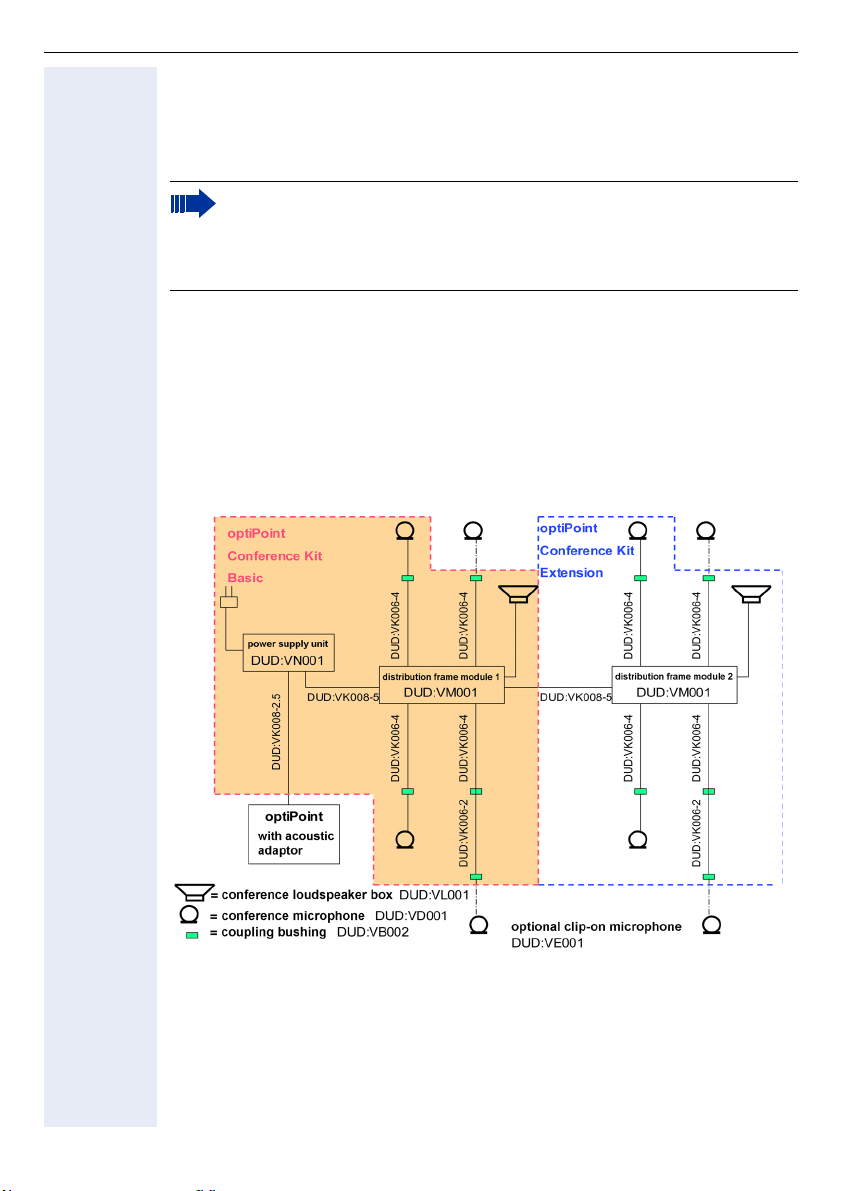
The optiPoint Basic and Extension Conference kits are complementary equipment to the optiPoint telephone with the optiPoint acoustic adapter (S30817K7110-B508).
For the optiPoint Basic and Extension Conference kit, only the supplied (or separately available) conference loudspeakers and conference microphones are
permitted. These were espoecially developed for the optiPoint Conference Kit.
Assembly and Start-up
Requirements: As manufactured, the optiPoint acoustic adapter is already approved for optiPoint telephones.
The illustration below shows how to connect the individual components.
War ning : The Y cable (L36453-Z5-C199) for direct connection with the
active loudspeaker (L30460-X1278-X) and desktop microphone (L30460X1279-X) are not needed here. The active loudspeaker and desktop microphone with direct connection mentioned above cannot be used with
the optiPoint Conference Kit.
48
Page 49

optiPoint Conference Kit
Assembly
The basic optiPoint Conference Kit contains a power supply unit, a distribution
frame module, a conference loudspeaker, two conference microphones as well
as cables and corresponding assembly materials (see scope of supply). The assembly materials also include the connection cables for two further optional microphones (alternatively available also as clip-on microphone), as well as two
supplementary connection cables and coupling bushing, in the event that the microphone connections need to be extended.
With the exception of the power supply unit and the connection cables to the
optiPoint acoustic adapter, the same components are found in the Extension
optiPoint Conference Kit.
The connection cable “DUD:VK008-2,5“ to the optiPoint acoustic adapter (symbol for loudspeaker/micro) from the power supply unit is provided with coded
connectors and should only be used for the connection FS-Power supply unit (labelled red).
War ning : It should never be connected with the output connector of the
power supply unit to the distribution frame module. For the connection
of the power supply unit to the distribution frame, respectively module 1
or module 2, the 5 metre cable “DUD:VK008-5“ should be used.
For a hidden configuration of the equipment, the distribution frame module and
power supply unit feature side mounting links, through which it is possible to attach the equipment under the table, in the event that there is no false floor.
Those in the set of assembly materials, with assembly holes and connectors 6/
4 are provided for the connection of the conference microphone. The connectors are suggested for use near the speaker's seat, to be brought under the
edge of the table, connected on one side with the connection cable
“DUD:VK006-4“ with the distribution frame module and on the other side with
the microphone.
The connection cable “DUD:VK006-4“ distribution frame module to coupling
bushing) can if needed be extended with the accessory cable “DUD:VK006-2“
and additional coupling bushings.
DeutschEnglishFrançaisNederlandsItalianoEspañolPortuguês
War ning : Only the cables found in the set should be used.
The conference loudspeaker is connected with the labelled connectors to the
distribution frame module. An additional power supply unit for the active loudspeaker is not required, as the power supply takes place via the module's power
supply unit.
The adhesive surfaces and cable clamps provided serve to hold the input leads
in place under the desk. By cabling all components together with plug connections the composition can be varied and can for example be transferred between
conference tables without difficulty, or great loss of time and can be adjusted to
the environment.
After installation has been completed the power supply unit is connected with
the mains supply (country-specific adapter plugs are provided locally).
The operating light (LED) on the loudspeaker and microphones flashes.
49
Page 50

optiPoint Conference Kit
Positioning
To avoid interference of the loudspeakers with the microphone, the loudspeaker
should not be placed in close proximity or direct alignment with the microphone.
With the tuning knob of the loudspeaker, only the default volume is adjusted to
the room conditions; after that, it should not be changed.
To adjust the default volume, select a very low level of the telephone's loudspeaker and store it (see the optiPoint instructions for use).
After pushing the telephone’s "Loudspeaker" button, the default volume on the
loudspeaker's tuning knob can be set by means of the dial tone or by conversation.
When using the extension to the conference loudspeaker, select an identical default volume.
Later adjustments should be made during conferences only by using the u and
v
keys of the optiPoint telephone.
With the "Micro sens." control on the gable end of the distribution frame module
you can adjust the sensitivity (threshold) of the conference microphone. Four
LEDs are assigned to the microphones and show the current adjustment.
In case of a perfectly adjusted sensitivity only the LED of the currently used microphone should be illuminated and shoud swich off all microphones in conversation breaks.
To avoid the impression of a broken connection, it is possible to dub over a residual of the ambient noise. This is done with the "Room noise" control on the
gable end of the distribution frame module.
The room's acoustic characteristics and this positioning should be adjusted in a
few trial conversations. The optimal positioning should be identical for both distribution frame modules.
50
The optiPoint Conference Kit, together with the full-duplex hands-free capability of the optiPoint telephone, requires that at the beginning of a conference, as well as with sudden changes in the room acoustics, you
should always take a few seconds to adjust the quality of coverage to
changes in room conditions. This is only technically feasible if during this
stage only one participant speaks. In the menu settings of the optiPoint
handsfree (see optiPoint instructions for use) you may find further optimization possibilities, to adjust the speech quality for muffled, normal or
echoing room acoustics.
Page 51

optiPoint Conference Kit
Technical Information
Power supply unit Primary: 230V AC, 30 VA
Secondary:24 V DC stabilised
5 V DC stabilised
Current consumption: 60mA Primary
Material: PS/Polystorol
Protection category: IP 40
Dimensions: 150 x 80 x 55 mm
Distribution frame
module
Conference loudspeaker Amplifying capacity: 7 Watt
Conference microphone Acoustic mode of operation, pressure receiver
Conference clip-on microphone
4 conference microphone inputs with respective flow-operated amplifiers and separate audio level-related automatic shutdown device
Mute electronic shutdown device for all channels
1 loudspeaker unit connection with power supply
Output connector for 2 distribution frame modules or radio micro-
phones
Regulator for microphone sensitivity
Regulator for background noise in the room
Frequency domain: 100 Hz - 16 kHz
NF-input impedance: 10 K
Current consumption: 30/170mA (idle/load)
Connection cable: 2 m with "Miniwestern" plug
Dimensions: 160 x 98 x 95 mm
Colour: manganese
Weight: approx. 450 g
Frequency domain: 100 Hz - 7 kH
Characteristics: Kidney
Output impedance: 10 K
Voltage supply: 5 V DC
Current consumption: 6 mA
Connection cable: 0.80 m
Dimensions: 25 x 68 x 77 mm
Colour: manganese
Acoustic mode of operation, pressure receiver
Frequency domain: 100 Hz - 7 kHz
Characteristics: Kidney
Output impedance: 10 K
Voltage supply: 5 V DC
Current consumption: 4 mA
Connection cable: 1.40 m
Dimensions housing: 65 x 46 x 16 mm
microphone: 20 x 13 mm
Ω
Ω
Ω
DeutschEnglishFrançaisNederlandsItalianoEspañolPortuguês
51
Page 52

optiPoint Conference Kit
CE statement
War ning :
The loudspeaker and conference microphone should only be used with
optiPoint Conference Kit.
Turn the conference clip-on microphone’s power switch to "ON" before
start-up.
This equipment complies with the requirements of the EU directives 99/5/EEC:
EN 60950: 2000 Safety
EN 55022: 1998 Class B EMC, Emission ITE Residential
Environment
EN 55024: 1998 EMC, Immunity ITE Residential
Environment
52
Page 53

optiPoint Conference Kit
Scope of supply for the Order Items
optiPoint Conference Kit Basic (L30250-F600-A605)
For connection to the optiPoint acoustic adapter for 1 conference loudspeaker
unit/ max. 4 conference microphones:
Scope of supply Order number
1 conference loudspeaker unit manganese, with connection cable 2 m DUD:VL001
2 conference microphones manganese, with connection cable 0.8 m DUD:VD001
1 power supply unit 230V AC, 24V + 5V DC for max. 2 loudspeakers/
8 microphones
1 distribution frame module with
– 1 input for power supply unit
– 1 output to optiPoint conference kit extension
– max. 4 outputs to conference microphone
– 1 output to conference loudspeaker unit
1 connection cable power supply unit - optiPoint acoustic adapter 2.5 m DUD:VK008-2.5
1 connection cable power supply unit - distribution frame module 5 m DUD:VK008-5
1 set assembly materials
– 4 connection cables distribution frame module - conference mi-
crophone 4 m
– 2 extension cables to conference microphone 2 m
– 6 coupling bushings for microphone with respective cable exten-
sion
DUD:VN001
DUD:VM001
DUD:VZ001
DeutschEnglishFrançaisNederlandsItalianoEspañolPortuguês
optiPoint Conference Kit Extension (L30250-F600-A606)
For extension to 1 conference loudspeaker unit and max. 4 conference microphones:
Scope of supply Order number
1 conference loudspeaker unit manganese, with connection cable 2 m DUD:VL001
2 conference microphones manganese, with connection cable 0.8 m DUD:VD001
1 distribution frame module with
– 1 input for basic distribution frame module
– max. 4 outputs to conference microphones
– 1 output to conference loudspeaker unit
1 connection cable distribution frame module - distribution frame module 5 m
1 set assembly materials
– 4 connection cables distribution frame module - conference mi-
crophone 4 m
– 2 extension cables to conference microphone 2 m
– 6 coupling bushings for microphone with respective cable exten-
sion
For each extension of the optiPoint Conference Kit or extension with 4 microphones, also available are:
DUD:VM001
DUD:VK008-5
DUD:VZ001
53
Page 54

optiPoint Conference Kit
Conference microphone (L30250-F600-A607)
For the extension as appropriate (for Basic/Extension) max. 4 conference microphones:
Scope of supply Order number
1 conference microphone (manganese) DUD:VD001
Conference Clip-on microphone (L30250-F600-A608)
For the extension as appropriate (for Basic/Extension) max. 4 conference microphones:
Scope of supply Order number
1 conference clip-on microphone DUD:VE001
54
Page 55
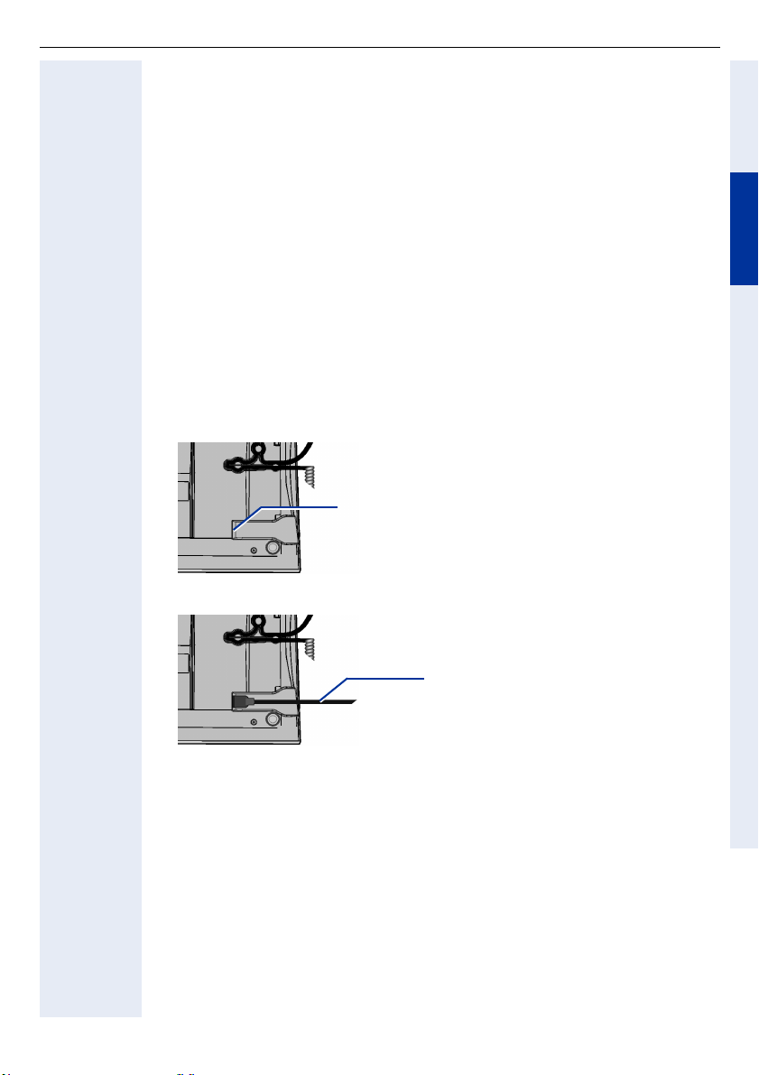
USB keyboard
USB keyboard
Safety Notes
• Avoid exposing the equipment to direct sunlight or other sources of heat.
• Protect the equipment from moisture and liquids.
• Never insert objects into openings in the equipment.
Applications
The USB keyboard can be connected to the following telephones:
optiPoint 410 advance, optiPoint 420 advance, optiPoint 600 office.
With the USB keyboard, you can edit key label text, directory entries
(optiPoint 420 advance only) and setup parameters for your optiPoint telephone.
Installation
1. Disconnect the subscriber line from the optiPoint telephone.
2. Place the telephone on a soft surface with the keypad facing down.
The USB port (USB master) is on the lower
right side of the baseplate.
DeutschEnglishFrançaisNederlandsItalianoEspañolPortuguês
3. Insert the plug on the USB keyboard’s cord into the USB port.
Plug with cord for USB keyboard.
4. Reconnect the subscriber line to the optiPoint telephone.
The USB keyboard is ready for operation.
55
Page 56
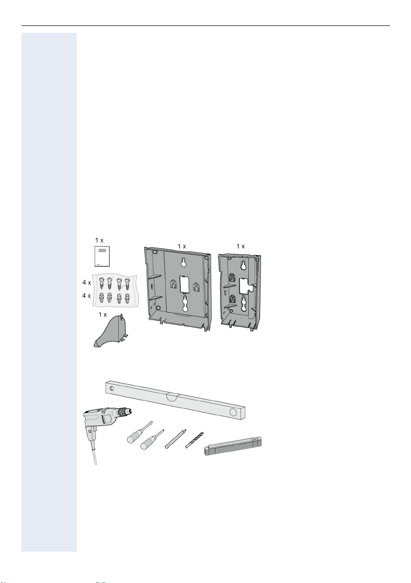
Wall Mount Unit
Wall Mount Unit
Safety Notes
To assure problem-free operation, take the following factors into consideration
while planning system installation.
• The telephone must be properly centered; take cable lengths into account.
• The telephone should be used in a well-ventilated area with temperatures
between +5 °C and +40 °C, with a maximum humidity of 95%.
• Protect the equipment from liquids, flammable materials, excess dust, vibration and mechanical stress.
• The system should not be installed where it can be exposed to direct sunlight, dust, humidity, excessive heat or cold, or next to electric cables.
• Avoid proximity to data transmission equipment, electric soldering machines, copying machines, personal computers, and other electric equipment which may cause electric interference.
• Do not install inside cabinets.
Package Contents
56
orType 1 Type 2
Tools Needed
Installation
For installation, see fold-out page 3.
Page 57

F
rançais
Satellites
optiPoint key module/optiPoint BLF
optiPoint key module/optiPoint BLF
L'optiPoint BLF ne peut être raccordé à la plate-forme de communication
HiPath 4000.
DeutschEnglishFrançaisNederlandsItalianoEspañolPortuguês
Consignes de sécurité
Les téléphones et Satellites optiPoint répondent aux exigences de conformité et
de sécurité en vigueur (norme CE).
• Ne pas exposer les appareils directement aux rayons du soleil ou à toute
autre source de chaleur.
• Protéger les appareils de l’humidité ou des risques d’infiltration de liquide.
• Ne jamais introduire d’objet dans les ouvertures de l’appareil.
Utilisation
Le key module/BLF peut être raccordé aux téléphones :
optiPoint 600 office, optiPoint 500 advance/standard/basic,
optiPoint 420 advance/standard, optiPoint 410 advance/standard,
optiPoint 400 standard.
Le key module/BLF vous permet d’utiliser 16/90 touches de fonction / nominatives supplémentaires.
Selon votre type d’installation téléphonique, vous pouvez raccorder plusieurs
key modules à votre optiPoint (2 maxi.).
Certaines configurations peuvent nécessiter l’emploi d’un bloc-secteur enfichable.
Contenu de l’emballage
• 1 optiPoint key module/optiPoint BLF
• 1 cordon de raccordement
Montage
Pour le montage, consultez aussi la page dépliante 3 (Positions à ).
1. Déconnecter le cordon de raccordement du téléphone optiPoint.
2. Poser le téléphone sur un support non rigide, clavier vers le bas.
3. Encastrer le key module/BLF dans le mécanisme à enclenchement du
téléphone prévu à cet effet ou dans celui du key module raccordé.
4. Relier le key module/BLF au téléphone optiPoint ou au key module avec le
câble de raccordement livré.
5. Insérer sur le key module les étiquettes de libellés et le cache plastique.
6. Reconnecter le téléphone optiPoint avec le cordon de raccordement.
Le téléphone optiPoint et le optiPoint key module/BLF sont prêts à fonctionner.
57
Page 58

optiPoint signature module
optiPoint signature module
L'optiPoint signature module ne peut être raccordé qu'à la plate-forme de
communication HiPath 4000
Consignes de sécurité
Les téléphones et Satellites optiPoint répondent aux exigences de conformité et
de sécurité en vigueur (norme CE).
• Ne pas exposer les appareils directement aux rayons du soleil ou à toute
autre source de chaleur.
• Protéger les appareils de l’humidité ou des risques d’infiltration de liquide.
• N'introduisez aucun objet dans les ouvertures de l’appareil, à l’exception de
la carte à mémoire.
• Utilisez uniquement les cartes à mémoire fournies par le responsable système.
Utilisation
L'optiPoint signature module peut être raccordé aux téléphones suivants :
optiPoint 600 office, optiPoint 500 advance/standard/basic,
optiPoint 420 advance/standard, optiPoint 410 advance/standard,
optiPoint 400 standard.
L'optiPoint signature module est un lecteur de carte à mémoire, qui facilite l’utilisation de fonctions protégées par un PIN.
58
Contenu de l’emballage
• 1 optiPoint signature module
• 1 Câble de raccordement
Montage
Pour le montage, consultez aussi la page dépliante 3 (Positions à ).
1. Déconnecter le cordon de raccordement du téléphone optiPoint.
2. Poser le téléphone sur un support non rigide, clavier vers le bas.
3. Encastrer l'optiPoint signature module dans le mécanisme à enclenchement du téléphone prévu à cet effet ou dans celui du module de touche
raccordé.
4. Relier l'optiPoint signature module au téléphone optiPoint ou au module de
touche avec le câble de raccordement livré.
5. Reconnecter le cordon de raccordement au téléphone optiPoint.
Le téléphone optiPoint et l'optiPoint signature module sont prêts à fonctionner.
Page 59

optiPoint display module/optiPoint application module
optiPoint display module/
optiPoint application module
Consignes de sécurité
Les téléphones et Satellites optiPoint répondent aux exigences de conformité et
de sécurité en vigueur (norme CE).
• Ne pas exposer les appareils directement aux rayons du soleil ou à toute
autre source de chaleur.
• Protéger les appareils de l’humidité ou des risques d’infiltration de liquide.
• Ne jamais introduire d’objet dans les ouvertures de l’appareil.
Utilisation
L'optiPoint display module peut être raccordé aux téléphones suivants :
optiPoint 410 advance/standard, optiPoint 420 advance/standard.
L'optiPoint application module peut être raccordé aux téléphones suivants :
optiPoint 410 advance/standard, optiPoint 420 advance/standard,
optiPoint 500 basic/standard/advance.
L'optiPoint display module/optiPoint application module vous supporte lorsque
vous téléphonez et offre de nombreuses fonctions utiles par son interface utilisateur graphique et son afficheur à touches sensitives.
Contenu de l’emballage
• 1 optiPoint display module/optiPoint application module
• 1 Câble de raccordement
Montage
Pour le montage, consultez aussi la page dépliante 3 (Positions à ).
1. Déconnecter le cordon de raccordement du téléphone optiPoint.
2. Poser le téléphone sur un support non rigide, clavier vers le bas.
3. Encastrer l'optiPoint display module dans le mécanisme à enclenchement
du optiPoint téléphone prévu à cet effet.
4. Relier l'optiPoint display module au téléphone optiPoint avec le câble de raccordement livré.
DeutschEnglishFrançaisNederlandsItalianoEspañolPortuguês
5. Reconnecter le cordon de raccordement au téléphone optiPoint.
Le téléphone optiPoint et l'optiPoint display module/
optiPoint application module sont prêts à fonctionner.
59
Page 60

optiPoint self labelling key module
optiPoint self labelling key module
Consignes de sécurité
Les téléphones et Satellites optiPoint répondent aux exigences de conformité et
de sécurité en vigueur (norme CE).
• Ne pas exposer les appareils directement aux rayons du soleil ou à toute
autre source de chaleur.
• Protéger les appareils de l’humidité ou des risques d’infiltration de liquide.
• Ne jamais introduire d’objet dans les ouvertures de l’appareil.
Utilisation
Le optiPoint self labelling key module peut être raccordé aux téléphones :
optiPoint 410 advance/standard, optiPoint 420 advance/standard.
Le optiPoint self labelling key module vous permet d’utiliser 13 touches de fonction / nominatives supplémentaires.
Selon votre type d’installation téléphonique, vous pouvez raccorder plusieurs
optiPoint self labelling key modules à votre optiPoint (2 maxi.).
Contenu de l’emballage
• 1 optiPoint self labelling key module
• 1 cordon de raccordement
Montage
60
Pour le montage, consultez aussi la page dépliante 3 (Positions à ).
1. Déconnecter le cordon de raccordement du téléphone optiPoint.
2. Poser le téléphone sur un support non rigide, clavier vers le bas.
3. Encastrer le optiPoint self labelling key module dans le mécanisme à enclenchement du téléphone prévu à cet effet ou dans celui du
optiPoint self labelling key module raccordé.
4. Relier le optiPoint self labelling key module au téléphone optiPoint ou au
optiPoint self labelling key module avec le câble de raccordement livré.
5. Reconnecter le téléphone optiPoint avec le cordon de raccordement.
Le téléphone optiPoint et le optiPoint self labelling key module sont prêts à fonctionner.
Page 61
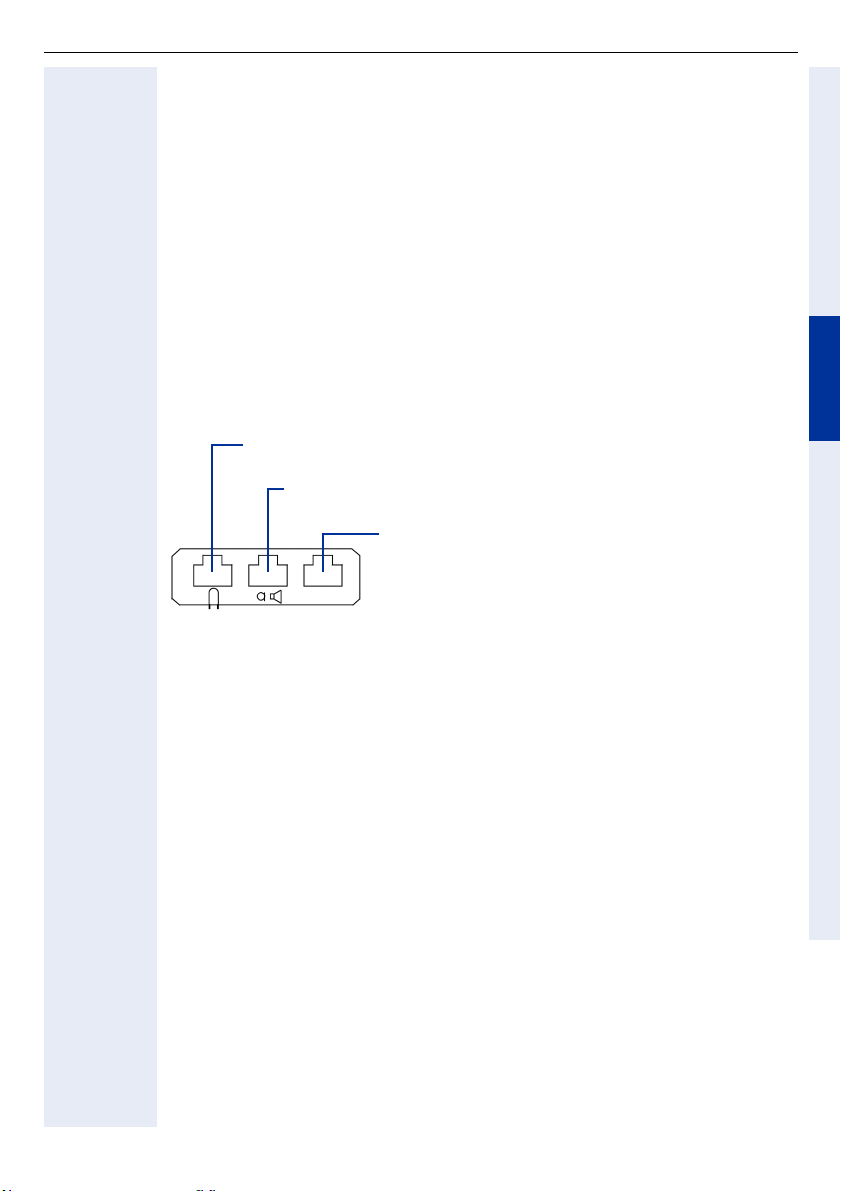
optiPoint acoustic adapter
C
optiPoint acoustic adapter
Consignes de sécurité
Les téléphones et adaptateurs optiPoint répondent aux exigences de conformité
et de sécurité en vigueur (norme CE).
• Ne pas exposer les appareils directement aux rayons du soleil ou à toute
autre source de chaleur.
• Protéger les appareils de l’humidité ou des risques d’infiltration de liquide.
• Ne jamais introduire d’objet dans les ouvertures de l’appareil.
Utilisation
L’adaptateur acoustique peut être raccordé aux téléphones suivants :
optiPoint 600 office, optiPoint 500 advance/standard/basic,
optiPoint 420 advance/standard, optiPoint 410 advance/standard.
L’adaptateur acoustique dispose de trois prises pour :
asque d'écoute et microphone (filaires 121TR9-5/ sans fil
121TR9-5*) :raccordement à un mini connecteur western 8/8
enceinte active et microphone à électret : raccordement à un
mini connecteur western 8/8 par câble en Y (L36453-Z5-C199)
2 dispositifs d'avertissement, par exemple une
seconde sonnerie (24 VAC/60 VDC, 5W) et une lampe d'occupation ou une gâche de porte
Raccordement à un connecteur mini western 6/6,
isolé galvaniquement
DeutschEnglishFrançaisNederlandsItalianoEspañolPortuguês
Contenu de l’emballage
• 1 optiPoint acoustic adapter
Montage
Pour le montage, consultez aussi la page dépliante 3 (Positions à ).
1. Déconnecter le cordon de raccordement du téléphone optiPoint.
2. Poser l’optiPoint , clavier vers le bas, sur un support non rigide.
3. Tenir l’adaptateur , barrette de raccordement dirigée vers le bas, et emboîter les deux ergots dans les encoches correspondantes de l’un des deux
emplacements de montage situés sous le téléphone.
4. Faire glisser sans forcer l’adaptateur jusqu’en butée .
5. Les trois prises situées au dos de l’adaptateur acoustique permettent à présent de raccorder les équipements supplémentaires (identifiés par des symboles).
6. Reconnecter le téléphone optiPoint avec le cordon de raccordement.
Le téléphone optiPoint et l’adaptateur sont prêts à fonctionner.
61
Page 62

optiPoint analog adapter
optiPoint analog adapter
Consignes de sécurité
Les téléphones et adaptateurs optiPoint répondent aux exigences de conformité
et de sécurité en vigueur (norme CE).
• Ne pas exposer les appareils directement aux rayons du soleil ou à toute
autre source de chaleur.
• Protéger les appareils de l’humidité ou des risques d’infiltration de liquide.
• Ne jamais introduire d’objet dans les ouvertures de l’appareil.
Utilisation
l’adaptateur analogique peut être raccordé aux téléphones :
optiPoint 600 office, optiPoint 500 advance/standard/basic.
L’adaptateur analogique vous permet de raccorder un poste supplémentaire, un
fax, un modem (p. ex. :un PC avec une carte modem intégrée) ou bien un répondeur, avec interface analogique et sur numérotation MF.
Avec des téléphones analogiques, l’adaptateur analogique nécessite l’utilisation
d’un bloc secteur enfichable externe.
Un seul adaptateur analogique est autorisé pour chaque raccordement
U
P0/E
Contenu de l’emballage
• 1 optiPoint analog adapter
.
62
Montage
Pour le montage, consultez aussi la page dépliante 3 (Positions à ).
1. Déconnecter le cordon de raccordement du téléphone optiPoint.
2. Poser l’optiPoint , clavier vers le bas, sur un support non rigide.
3. Tenir l’adaptateur , barrette de raccordement dirigée vers le bas, et emboîter les deux ergots dans les encoches correspondantes de l’un des deux
emplacements de montage situés sous le téléphone.
4. Faire glisser sans forcer l’adaptateur jusqu’en butée .
5. La prise à 6 broches située au dos de l’adaptateur analogique permet de raccorder un terminal analogique (a / b sur les broches 3 et 4).
6. Reconnecter le téléphone optiPoint avec le cordon de raccordement.
Le téléphone optiPoint et l’adaptateur sont prêts à fonctionner.
Page 63

optiPoint ISDN adapter
optiPoint ISDN adapter
Consignes de sécurité
Les téléphones et adaptateurs optiPoint répondent aux exigences de conformité
et de sécurité en vigueur (norme CE).
• Ne pas exposer les appareils directement aux rayons du soleil ou à toute
autre source de chaleur.
• Protéger les appareils de l’humidité ou des risques d’infiltration de liquide.
• Ne jamais introduire d’objet dans les ouvertures de l’appareil.
Utilisation
L’adaptateur RNIS peut être raccordé aux téléphones :
optiPoint 600 office, optiPoint 500 advance/standard/basic.
L’adaptateur RNIS fournit un accès de base S
Les terminaux S
La prise se situe au dos de l’adaptateur.
Un seul adaptateur RNIS est autorisé pour chaque
raccordement U
doivent disposer de leur propre alimentation.
0
.
P0/E
Contenu de l’emballage
• 1 optiPoint ISDN adapter
Montage
RNIS aux terminaux S0.
0
DeutschEnglishFrançaisNederlandsItalianoEspañolPortuguês
Pour le montage, consultez aussi la page dépliante 3 (Positions. à ).
1. Déconnecter le cordon de raccordement du téléphone optiPoint.
2. Poser le téléphone sur un support non rigide, clavier vers le bas.
3. L’adaptateur s’emboîte dans un des deux emplacements de montage situés sous le téléphone. Pour ce faire, insérer les deux argots de l’adaptateur dans les deux encoches du téléphone.
4. Faire glisser l’adaptateur dans le sens de la flèche et sans forcer, jusqu’à
la butée.
5. Grâce à l’ adaptateur RNIS, il est possible de raccorder jusqu’à deux terminaux RNIS sur un bus S
résistances de terminaison de 100 . Les appareils RNIS ne peuvent néanmoins pas fonctionner simultanément, car un seul canal B est disponible.
6. Reconnecter le téléphone optiPoint avec le cordon de raccordement.
Le téléphone optiPoint et l’adaptateur sont prêts à fonctionner.
d’une longueur maximale de 150 m pourvu de deux
0
Ω
63
Page 64

optiPoint phone adapter
optiPoint phone adapter
Consignes de sécurité
Les téléphones et adaptateurs optiPoint répondent aux exigences de conformité
et de sécurité en vigueur (norme CE).
• Ne pas exposer les appareils directement aux rayons du soleil ou à toute
autre source de chaleur.
• Protéger les appareils de l’humidité ou des risques d’infiltration de liquide.
• Ne jamais introduire d’objet dans les ouvertures de l’appareil.
Utilisation
L’adaptateur téléphonique peut être raccordé aux téléphones :
optiPoint 600 office, optiPoint 500 advance/standard/basic.
L’adaptateur téléphonique vous permet de raccorder un second téléphone optiPoint sans utiliser de câble spécifique.
La prise se trouve au dos de l’adaptateur.
Un seul adaptateur téléphonique est autorisé pour chaque raccordement
U
P0/E
Contenu de l’emballage
• 1 optiPoint phone adapter
Montage
.
64
Pour le montage, consultez aussi la page dépliante 3 (Positions à ).
1. Déconnecter le cordon de raccordement du téléphone optiPoint.
2. Poser l’optiPoint , clavier vers le bas, sur un support non rigide.
3. Tenir l’adaptateur , barrette de raccordement dirigée vers le bas, et emboîter les deux ergots dans les encoches correspondantes de l’un des deux
emplacements de montage situés sous le téléphone.
4. Faire glisser sans forcer l’adaptateur jusqu’en butée .
5. La prise à six broches située au dos de l’adaptateur téléphonique permet de
raccorder un second téléphone optiPoint (de quelque type que ce soit).
6. Reconnecter le téléphone optiPoint avec le cordon de raccordement.
Le téléphone optiPoint et l’adaptateur sont prêts à fonctionner.
Page 65
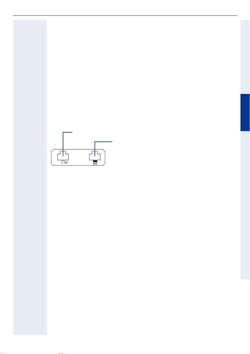
optiPoint recorder adapter
optiPoint recorder adapter
Consignes de sécurité
Les téléphones et adaptateurs optiPoint répondent aux exigences de conformité
et de sécurité en vigueur (norme CE).
• Ne pas exposer les appareils directement aux rayons du soleil ou à toute
autre source de chaleur.
• Protéger les appareils de l’humidité ou des risques d’infiltration de liquide.
• Ne jamais introduire d’objet dans les ouvertures de l’appareil.
Utilisation
L’adaptateur recorder peut être raccordé aux téléphones suivants :
optiPoint 600 office, optiPoint 500 advance/standard/basic,
optiPoint 420 advance/standard, optiPoint 410 advance/standard.
L’adaptateur recorder dispose de prises pour :
Ecouteur auxiliaire raccordé au connecteur RJ11 à 4 pôles
Appareil d'enregistrement (Recorder) raccordé
au connecteur femelle RJ11 à 6 pôles
Contenu de l’emballage
• 1 optiPoint recorder adapter
DeutschEnglishFrançaisNederlandsItalianoEspañolPortuguês
Montage
Pour le montage, consultez aussi la page dépliante 3 (Positions à ).
1. Déconnecter le cordon de raccordement du téléphone optiPoint.
2. Poser le téléphone sur un support non rigide, clavier vers le bas.
3. L’adaptateur s’emboîte dans un des deux emplacements de montage situés sous le téléphone. Pour ce faire, insérer les deux argots de l’adaptateur dans les deux encoches du téléphone.
4. Faire glisser l’adaptateur dans le sens de la flèche et sans forcer, jusqu’à
la butée.
5. Raccorder l'écouteur auxiliaire et l'appareil d'enregistrement au(x) connecteur(s) femelle d'adaptation repéré(s).
6. Reconnecter le cordon de raccordement au téléphone optiPoint.
Le téléphone optiPoint et l’adaptateur sont prêts à fonctionner.
65
Page 66

F
rançais
Accessoires
Enceinte active
Enceinte active
Consignes de sécurité
• Ne pas exposer les appareils aux rayons directs du soleil ou à d’autres sources de chaleur.
• Protéger les appareils de l’humidité ou de toute pénétration de liquides.
• Ne jamais introduire d’objets dans les ouvertures de l’appareil.
Possibilités de raccordement
L'enceinte active peut être raccordée seule ou conjointement au microphone de
table par l'adaptateur acoustique optiPoint (S30817-K7110-B508) et un câble en
Y (L36453-Z5-C199) aux téléphones suivants :
optiPoint 600 office, optiPoint 500 advance/standard/basic,
optiPoint 420 advance/standard, optiPoint 410 advance/standard.
Généralités
L’enceinte active améliore la qualité sonore de l’écoute amplifiée. Le raccordement de l’enceinte coupe le haut-parleur interne du téléphone. Lorsque vous appuyez sur la touche “Haut-parleur“ du téléphone, l’écoute amplifiée a lieu uniquement via l’enceinte.
L’enceinte peut être posée ou bien accrochée au mur à l’aide d’une équerre.
Contenu de la livraison
• 1 enceinte active avec câble de raccordement (2 m)
• 1 bloc-secteur enfichable 230 V/22 V ac avec câble de raccordement (2 m)
• 1 pièce en matière plastique + 1 vis de fixation pour montage mural
• 1 instructions de montage
66
Page 67

Enceinte active
Mise en service
Attention !
Utiliser uniquement le bloc-secteur fourni !
Condition préalable : monter de manière conforme l’adaptateur correspondants sur le téléphone.
1. Tourner le bouton à l’avant de l’enceinte jusqu’en butée gauche (volume le
plus faible).
2. Brancher la fiche mini-western 8/8 du Y câble dans la prise de raccorde-
ment de l’adaptateur.
3. Brancher la fiche cordon de raccordement dans la prise de raccordement
de la Y câble.
4. Brancher la fiche coudée du bloc-secteur fourni dans la prise ronde du so-
cle du haut-parleur.
5. Ne jamais placer l’enceinte à proximité du téléphone ou du microphone
supplémentaire afin éviter les perturbations acoustiques.
6. Enficher le bloc-secteur dans la prise 230 V.
Le voyant Prêt à fonctionner (LED) à l’avant de l’enceinte s’allume.
7. Régler le volume de base :
Le bouton de l’enceinte sert uniquement à régler le volume en fonction des
conditions de la pièce et ne doit plus être modifié.
Procédure de réglage :
• Régler et mémoriser le volume du haut-parleur du téléphone sur le niveau le plus faible, voir mode d’emploi du téléphone.
• Activer l’écoute amplifiée grâce à la touche “Haut-parleur“.
• Régler par exemple durant la tonalité d’invitation à numéroter ou en cours de
communication le volume de base (volume normal) à l’aide du bouton de
l’enceinte
DeutschEnglishFrançaisNederlandsItalianoEspañolPortuguês
Utilisation
Pour activer et désactiver la fonction Ecoute amplifiée, utiliser la touche “Hautparleur“ du téléphone. Pour modifier le volume actuel de l’enceinte, utiliser uniquement les touches “+“ et “–“ du téléphone.
67
Page 68

Enceinte active
Montage mural
1. Retirer le pied arrière situé sous l’enceinte (téton).
2. Insérer la pièce en matière plastique fournie dans l’ouverture.
3. La pièce en matière plastique et la vis fournie permettent de fixer l’enceinte
par exemple sur une équerre (non fournie).
Remarque : la pièce en matière plastique et la vis ne conviennent pas pour un
montage mural direct !
Caractéristiques technique
Alimentation : Uniquement bloc-secteur fourni :
L30460-X1325-X ; pour GB :
L30460-X1325-X1
230 V ac +6% / –10% / 22 V ac ; 50 Hz;
Câble de raccordement 2 m ; avec fiche coudée
Puissance : 7 Watt
Plage de fréquences : 100 Hz–16 kHz
Sensibilité de réception : 250 mV (niveau maximal)
Impédance : 10 k
Câble de raccordement : 2 m ; avec fiche mini-western 4/4
Dimensions : 160 x 98 x 95 (h x l x p, mm)
Poids : environ 500 g
Desk microphone
Ω
68
Page 69

Microphone supplémentaire
Microphone supplémentaire
Consignes de sécurité
• Ne pas exposer les appareils aux rayons directs du soleil ou à d’autres sources de chaleur.
• Protéger les appareils de l’humidité ou de toute pénétration de liquides.
• Ne jamais introduire d’objets dans les ouvertures de l’appareil.
Possibilités de raccordement
Le microphone de table peut être raccordé seul ou conjointement à l'enceinte
active de table par l'adaptateur acoustique optipoint (S30817-K7110-B508) et un
câble en Y (L36453-Z5-C199) aux téléphones suivants :
optiPoint 600 office, optiPoint 500 advance/standard/basic,
optiPoint 420 advance/standard, optiPoint 410 advance/standard.
Généralités
Le microphone supplémentaire améliore la qualité sonore, par exemple lors
d’une conférence. Le raccordement du microphone supplémentaire coupe le
microphone interne du téléphone. Lorsque vous appuyez sur la touche “Hautparleur“ du téléphone, le mains-libres a lieu uniquement via le microphone supplémentaire.
Contenu de la livraison
• 1 microphone supplémentaire avec câble de raccordement (2 m)
• 1 instructions de montage
DeutschEnglishFrançaisNederlandsItalianoEspañolPortuguês
Mise en service
1. Brancher la fiche mini-western 8/8 du Y câble dans la prise de raccordement de l’adaptateur.
2. Brancher la fiche cordon de raccordement dans la prise de raccordement
de la Y câble.
3. Ne jamais placer le microphone supplémentaire à proximité du téléphone
ou de l’enceinte afin d’éviter les perturbations acoustiques.
69
Page 70

Microphone supplémentaire
Utilisation
La fonction Mains-libres est activée / désactivée via la touche “Haut-parleur“ du
téléphone. Le voyant (LED) sur le dessus du microphone s’allume en position
Marche – lorsque le microphone est actif.
La touche Secret (touche Mute) permet de désactiver temporairement le microphone (l’affichage s’éteint), par exemple pour poser une question dans le bureau. Lorsque vous relâchez la touche Secret, le microphone est à nouveau actif.
Caractéristiques techniques
Mode acoustique : microphone à pression
Plage de fréquences : 100 Hz –7 kHz
Caractéristique : cardioïde
Impédance de sortie : 10 k
Tension d’alimentation : 3,8 V–6 V cc ; alimentation par adaptateur
Consommation courant : 6 mA maximum pour 3,8 V et LED activée
Câble de raccordement : 2 m ; avec fiche mini-western 4/4
Dimensions : 25 x 68 x 77 (h x l x p, mm)
Ω
via câble de raccordement
70
Page 71

optiPoint Conference Kit
optiPoint Conference Kit
Généralités
optiPoint Conference Kit améliore la qualité du mains-libres pour les conférences téléphoniques, notamment lorsque les sièges des participants sont dispersés dans une salle de conférence. Dans la configuration maximum, 2 enceintes
et 8 microphones de conférence
acoustique optimale de la pièce. Les microphones sont dotés chacun d’un système électronique d’amplification et de commande grâce auquel seuls les microphones actuellement utilisés sont ouverts, ce qui permet de séparer nettement le niveau de bruit (écho de la pièce) du signal utile.
La sensibilité des microphones comme le niveau du bruit de fond peuvent être
réglés sur les modules de répartition, en fonction de l’acoustique de la pièce.
En cas de pauses dans la conversation, et donc désactivation des microphones,
cela évite de faire naître chez les participants l’impression qu’ils ont été coupés.
Chaque microphone dispose d’une touche Secret qui provoque la coupure de
tous les microphones de la conférence.
L’alimentation de l’optiPoint Conference Kit est fournie par un bloc-secteur propre.
Consignes de sécurité
• Ne pas exposer les appareils aux rayons directs du soleil ou à d’autres sources de chaleur.
• Protéger les appareils de l’humidité ou de toute pénétration de liquides.
• Ne jamais introduire d’objets dans les ouvertures de l’appareil.
1
peuvent être raccordés pour une couverture
DeutschEnglishFrançaisNederlandsItalianoEspañolPortuguês
[1] L’utilisation d’un microphone sans fil est également possible.
Pour toute question, adressez-vous à : [email protected]
71
Page 72
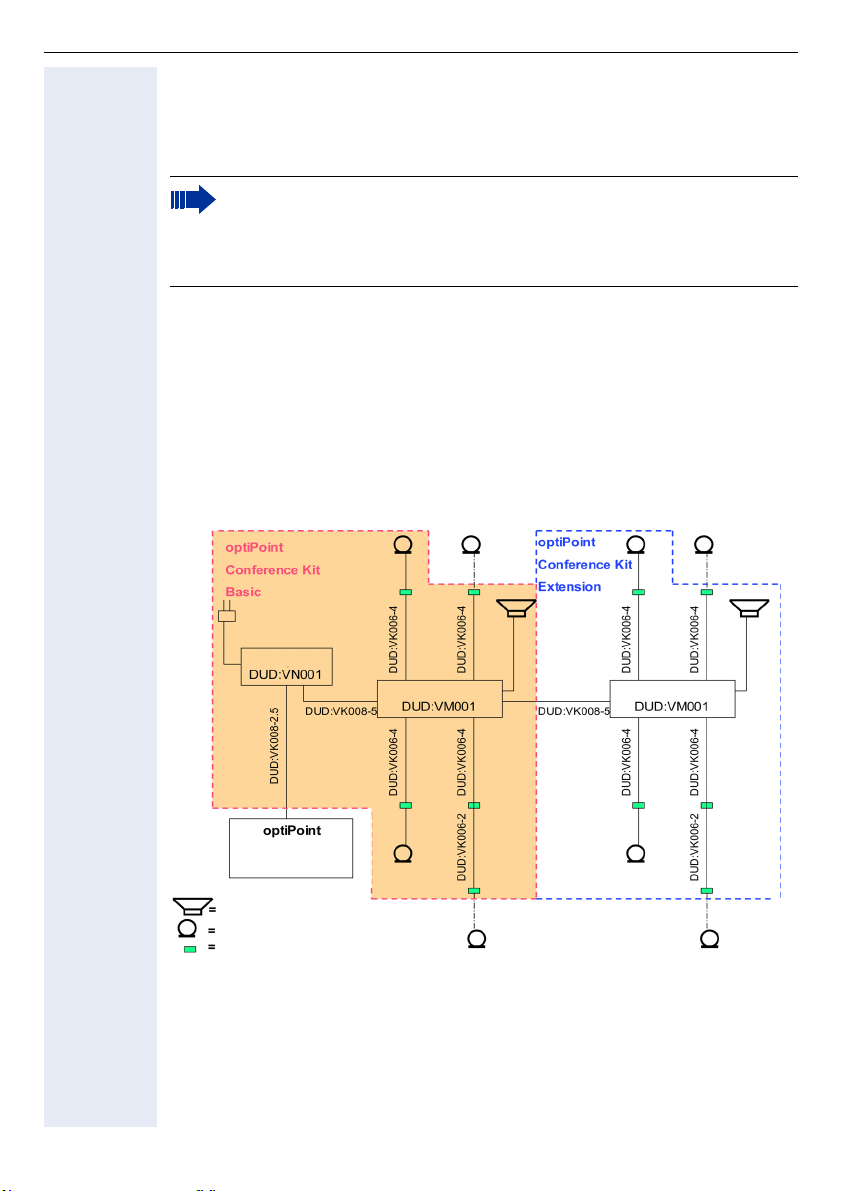
optiPoint Conference Kit
Possibilités de raccordement
L’optiPoint Conference Kit Basic/Extension est raccordé comme équipement
complémentaire sur les téléphones optiPoint avec optiPoint acoustic adapter
(S30817-K7110-B508).
Pour l’optiPoint Conference Kit Basic/Extension, seuls sont autorisés les en-
ceintes et microphones de conférence qui sont fournis à la livraison ou peuvent être commandés en option. Ils sont spécifiquement conçus pour
l’optiPoint Conference Kit.
Montage/Mise en service
Condition préalable : l’optiPoint acoustic adapter a déjà été intégré au téléphone optiPoint prévu comme indiqué dans les consignes.
La figure suivante présente le raccordement des différentes composantes.
Attention ! Le câble en Y (L36453-Z5-C199) qui sert à raccorder directement l’enceinte (L30460-X1278-X) et le microphone supplémentaire
(L30460-X1279-X) n’est pas nécessaire ici. Les enceintes et microphones
supplémentaires déjà décrits pour le raccordement direct ne peuvent pas
être utilisés sur l’optiPoint Conference Kit.
72
Bloc-secteur
Module de répartition 1
avec
acoustic Adapter
Enceinte de conférence DUD:VL001
Microphone de conférence DUD:VD001
Prise de prolongation DUD:VB002
Module de répartition 2
En option microphone cravate
DUD:VE001
Page 73

optiPoint Conference Kit
Montage
Font partie de l’équipement de base de l’optiPoint Conference Kit Basic un blocsecteur, un module de répartition, une enceinte de conférence, deux microphones de conférence ainsi que les câbles et le matériel de montage correspondant
(voir Contenu de la livraison). Le kit de matériel de montage comprend aussi les
câbles de raccordement pour 2 microphones supplémentaires en option (disponibles aussi au choix sous forme de microphones cravates), ainsi que deux câbles et prises de prolongation supplémentaires qui permettent de prolonger les
raccordements des microphones.
A l’exception du bloc-secteur et du câble de raccordement avec l’optiPoint
acoustic Adapter, l’optiPoint Conference Kit Extension comprend les mêmes
composantes.
Le câble de raccordement "DUD:VK008-2,5" de l’optiPoint acoustic Adapter
(symbole Haut-parleur/Micro) au bloc-secteur est doté de connecteurs codés et
ne peut être utilisé que pour le raccordement entre le poste et le bloc-secteur
(marquage rouge).
Attention ! Il ne doit en aucun cas être raccordé à la prise de sortie du
bloc-secteur vers le module de répartition. Pour la liaison entre le blocsecteur et le module de répartition ou entre le module de répartition 1 et
le module de répartition 2, vous devez utiliser le câble de 5 mètres
"DUD:VK008-5".
Pour un montage masqué du système, les modules de répartition et le bloc-secteur sont dotés de pièces latérales grâce auxquelles une fixation sous la table
est possible à condition qu’il y ait un double-fond. Les prises de raccordement
6/4 qui se trouvent dans le kit du matériel de montage et sont dotées d’ouvertures de montage sont destinées au raccordement des microphones de conférence. L’emplacement idéal pour les prises est à proximité de l’endroit où est
assis le participant, sous le bord de la table. Elles servent à raccorder d’une part
le câble "DUD:VK006-4" au module de répartition, d’autre part le microphone.
Les câbles de raccordement "DUD:VK006-4" (module de répartition à la prise de
prolongation) peuvent, si nécessaire, être prolongés par les câbles supplémentaires "DUD:VK006-2" qui se trouvent dans les kits avec des prises de prolongation supplémentaires.
DeutschEnglishFrançaisNederlandsItalianoEspañolPortuguês
Attention ! Seuls les câbles qui se trouvent dans le kit peuvent être utilisés.
L’enceinte de conférence se raccorde sur la prise correspondante du module de
répartition. Il n’est pas nécessaire d’avoir un bloc-secteur supplémentaire pour
le haut-parleur actif car l’alimentation est assurée par le bloc-secteur du module.
Les serre-câbles fournis avec surfaces adhésives servent à fixer les câbles sous
les tables. Le câblage de toutes les composantes par connecteurs permet d’utiliser le système de façon flexible et de l’adapter sans problème ni perte de
temps aux conditions données, par exemple si l’on éloigne les tables de conférence les unes des autres.
Lorsque l’installation est complètement terminée, raccordez le bloc-secteur à
l’alimentation (si un adaptateur est nécessaire, il est fourni localement).
73
Page 74

optiPoint Conference Kit
L’affichage d’exploitation (LED) sur l’enceinte et les microphones s’allume.
Réglages
Pour éviter que le haut-parleur ne perturbe acoustiquement (effet rétro-actif) les
microphones, il ne faut pas placer l’enceinte à proximité immédiate des microphones, ni les orienter directement vers eux.
Le bouton qui se trouve sur l’enceinte permet uniquement de régler le volume
de base qui doit être adapté à l’acoustique de la pièce et ne plus être modifié.
Avant d’ajuster ce volume de base, sélectionnez un volume très faible sur le
haut-parleur du téléphone et enregistrez-le (voir mode d’emploi optiPoint).
Après avoir appuyé sur la touche "Haut-parleur" du téléphone, vous pouvez régler le volume de base du haut-parleur avec ce bouton en vous aidant de la tonalité d’invitation à numéroter ou en suivant une communication.
Pour l’enceinte de conférence Extension, si vous l’utilisez, sélectionnez un volume de base identique.
Toute modification ultérieure du volume pendant la conférence ne doit plus se
faire qu’avec les touches u et v du téléphone optiPoint.
Le bouton de réglage "Micro sens." présent sur la face avant des modules de répartition permet de définir la sensibilité (valeur-seuil) des microphones de conférence.
Les 4 LED sont affectées aux microphones et servent au contrôle du réglage.
Si le réglage est optimal, seule la LED du microphone directement actif à ce moment précis doit s’allumer, tandis qu’en cas de pause dans la conversation, tous
les microphones sont coupés. Afin que les participants impliqués ne puissent
alors avoir l’impression que la communication est interrompue, vous avez la possibilité d’injecter un bruit ambiant résiduel en bruit de fond. cela se fait grâce au
bouton de réglage "Room noise" sur la face avant des modules de répartition.
Pour adapter tous les paramètres aux conditions acoustiques de la pièce, vous
devez réaliser plusieurs essais de communication. Les valeurs optimales doivent être choisies à l’identique sur les deux modules de répartition.
74
L’optiPoint Conference Kit associé à l’équipement mains-libres duplex intégral des téléphones optiPoint a toujours besoin d’un délai de quelques
secondes au début de la conférence, ainsi qu’en cas de modification soudaine de l’acoustique, pour adapter de façon optimale la qualité de la
transmission aux nouvelles conditions. Cette opération ne peut réussir,
pour des raisons techniques, que si durant ces phases, dans la mesure
du possible, un seul participant intervient. Dans le menu Mains-libres de
l’optiPoint (voir mode d’emploi optiPoint), vous trouvez une autre possibilité d’optimisation de la qualité du mains-libres en fonction de l’acoustique (son amorti, normal ou écho).
Page 75

optiPoint Conference Kit
Caractéristiques techniques
Bloc-secteur Primaire : 230V AC, 30 VA
Secondaire : 24 V DC stabilisée
Consommation courant : 60mA primaire
Matériau : PS (polystirol)
Type de protection : IP 40
Dimensions : 150 x 80 x 55 (h x l x p, mm)
Module de répartition 4 entrées de microphone de conférence avec pour chacun un am-
Haut-parleur de conférence
Microphone de conférence
Microphone cravate de
conférence
plificateur et système automatique de coupure en fonction du niveau sonore
Désactivation (Secret) de tous les canaux
1 raccordement pour enceinte avec alimentation
Prise de raccordement pour 2emodule de répartition ou micropho-
ne sans fil
Bouton de réglage de la sensibilité des microphones
Bouton de réglage du niveau du bruit de fond
Puissance : 7 Watt
Plage de fréquences : 100 Hz-16 kHz
Impédance d’entrée BF : 10 KOhm
Consommation courant : 30/170mA (repos/charge)
Câble de raccordement : 2 m ; avec fiche mini-western
Dimensions : 160 x 98 x 95 (h x l x p, mm)
Couleur : manganèse
Poids : environ 450 g
Mode acoustique : microphone à pression
Plage de fréquences : 100 Hz - 7 kH
Caractéristique : cardioïde
Impédance de sortie : 10 KOhm
Tension d’alimentation : 5 V DC
Consommation courant: 6 mA
Câble de raccordement : 0,80 m
Dimensions: 25 x 68 x 77 (h x l x p, mm)
Couleur : manganèse
Mode acoustique : microphone à pression
Plage de fréquences : 100 Hz - 7 kHz
Caractéristique : cardioïde
Impédance de sortie : 10 KOhm
Tension d’alimentation : 5 V DC
Consommation courant: 4 mA
Câble de raccordement : 1,40 m
Dimensions boîtier : 65 x 46 x 16 mm
5 V DC stabilisée
partie microphone : 20 x 13 mm
DeutschEnglishFrançaisNederlandsItalianoEspañolPortuguês
75
Page 76

optiPoint Conference Kit
Label CE
Attention !
Utiliser le haut-parleur et le microphone de conférence uniquement avec
l’optiPoint Conference Kit.
Avant la mise en service, mettre le bouton d’alimentation du microphone
cravate sur "ON".
This equipment complies with the requirements of the EU directives 99/5/EEC:
EN 60950: 2000 Safety
EN 55022: 1998 Class B EMC, Emission ITE Residential
Environment
EN 55024: 1998 EMC, Immunity ITE Residential
Environment
76
Page 77

optiPoint Conference Kit
Contenu de la livraison
optiPoint Conference Kit Basic (L30250-F600-A605)
Destiné au raccordement sur optiPoint acoustic adapter d’1 haut-parleur/
4 microphones de conférence maximum :
Contenu de la livraison Référence
1 haut-parleur de conférence manganèse, avec câble de raccordement 2mDUD:VL001
2 microphones de conférence manganèse, avec câble de raccorde-
ment 0,8 m
1 bloc-secteur 230V ca ; 24V+5V cc pour 2 haut-parleurs/8 microphones
de conférence
1 module de répartition avec
– 1 entrée en provenance du secteur
– 1 sortie vers optiPoint Conference Kit Extension
– 4 sorties maxi. pour les microphones de conférence
– 1 sortie pour le haut-parleur de conférence
1 Câble de raccordement Bloc-secteur - optiPoint acoustic Adapter
2,5 m
1 Câble de raccordement Bloc-secteur - Module de répartition 5 m DUD:VK008-5
1 kit de matériel de montage
– 4 câbles de raccordement Module de répartition - Microphone de
conférence 4 m
– 2 câbles de prolongation pour microphone de conférence 2 m
– 6 prises de prolongation pour microphones ou prolongation des
câbles
DUD:VD001
DUD:VN001
DUD:VM001
DUD:VK008-2.5
DUD:VZ001
optiPoint Conference Kit Extension (L30250-F600-A606)
Pour l’extension à 1 haut-parleur et 4 microphones de conférence maximum :
DeutschEnglishFrançaisNederlandsItalianoEspañolPortuguês
Contenu de la livraison Référence
1 haut-parleur de conférence manganèse, avec câble de raccordement 2mDUD:VL001
2 microphones de conférence manganèse, avec câble de raccorde-
ment 0,8 m
1 module de répartition avec
– 1 entrée en provenance du module de répartition Basic
– 4 sorties maxi. pour microphones de conférence
– 1 sortie pour haut-parleur de conférence
1 Câble de raccordement Module de répartition/Module de répartition 5mDUD:VK008-5
1 kit de matériel de montage
– 4 câbles de raccordement Module de répartition - Microphone de
conférence 4 m
– 2 câbles de prolongation pour microphone de conférence 2 m
– 6 prises de prolongation pour microphones ou prolongation des
câbles
DUD:VD001
DUD:VM001
DUD:VZ001
77
Page 78

optiPoint Conference Kit
Pour la configuration maximum de l’optiPoint Conference Kit Basic/Extension
avec 4 microphones, vous avez le choix entre les modèles suivants :
Microphone de conférence (L30250-F600-A607)
Pour l’extension à 4 microphones de conférence maxi. (par Basic/Extension) :
Contenu de la livraison Référence
1 microphone de conférence (manganèse) DUD:VD001
Microphone cravate de conférence (L30250-F600-A608)
Pour l’extension à 4 microphones de conférence maxi. (par Basic/Extension) :
Contenu de la livraison Référence
1 microphone cravate de conférence DUD:VE001
78
Page 79
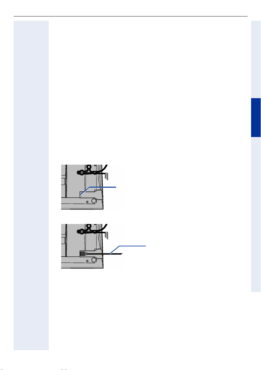
Clavier USB
Clavier USB
Consignes de sécurité
• Ne pas exposer les appareils aux rayons directs du soleil ou à d’autres sources de chaleur.
• Protéger les appareils de l’humidité ou de toute pénétration de liquides.
• Ne jamais introduire d’objets dans les ouvertures de l’appareil.
Possibilités de raccordement
Le clavier USB peut être raccordé sur les téléphones suivants :
optiPoint 410 advance, optiPoint 420 advance, optiPoint 600 office.
Le clavier USB représente une possibilité conviviale d’effectuer des entrées
dans l’annuaire, de créer des étiquettes de touches (optiPoint 420 advance uniquement) et de configurer votre téléphone optiPoint.
Mise en service
1. Déconnecter le cordon de raccordement du téléphone optiPoint.
2. Poser l’optipoint, clavier vers le bas, sur un support non rigide.
Le port USB (USB-Master) se trouve sur le
côté dans la partie inférieure droite du socle.
DeutschEnglishFrançaisNederlandsItalianoEspañolPortuguês
3. Enficher le cordon USB du clavier dans le port USB.
Connecteur avec cordon du clavier
USB.
4. Reconnecter le téléphone optiPoint avec le cordon de raccordement.
Le clavier USB est prêt à fonctionner.
79
Page 80
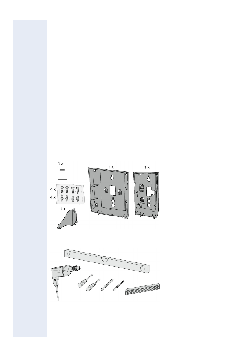
Support mural
Support mural
Consignes de sécurité
Pour un fonctionnement sans problème et une exploitation fiable, certains facteurs doivent être pris en compte pour bien planifier l’installation du système.
• Le téléphone doit être placé en un lieu central, ce qui implique de veiller particulièrement aux longueurs de câbles nécessaires.
• La plage de températures maximum autorisée pour l’exploitation se situe entre +5 °C et +40 °C, avec une humidité relative de 95% à ne pas dépasser.
• L’appareil ne doit pas être exposé à une humidité trop élevée, la présence de
matériaux inflammables, une poussière trop importante, des vibrations ou
des sollicitations mécaniques.
• Le système ne doit pas être monté dans un lieu directement exposé aux
rayons du soleil, à la poussière, à l’humidité, à une chaleur importante ou un
froid extrême et pas à proximité immédiate de câbles électriques.
• Eloignez-le de systèmes de transfert de données, de fers à souder électriques, d’appareils de copie, de PC et autres équipements électriques qui génèrent des champs électriques perturbateurs.
• Le poste ne doit pas être monté dans une armoire électrique.
Contenu de l’emballage
80
ouType 1 Type 2
Outils nécessaires
Montage
Pour le montage, consultez la page dépliante 2.
Page 81

Nederland
Uitbreidingsterminals
s
optiPoint key module/optiPoint BLF
optiPoint key module/optiPoint BLF
Het optiPoint BLF kan niet worden bediend op de communicatieplatform
HiPath 4000
DeutschEnglishFrançaisNederlandsItalianoEspañolPortuguês
Veiligheidvoorschriften
De optiPoint-toestellen en Uitbreidingsterminals voldoen aan de geldende eisen
met betrekking tot conformiteit en veiligheid (CE).
• Stel de telefoontoestellen niet bloot aan direct zonlicht of andere warmtebronnen.
• Stel de telefoontoestellen niet op in een vochtige omgeving en zorg ervoor
dat er geen vloeistoffen in de toestellen kunnen binnendringen.
• Steek geen voorwerpen in de toestelopeningen.
Toepassingsmogelijkheden
De key module/BLF kan aan onderstaande telefoons worden aangesloten:
optiPoint 600 office, optiPoint 500 advance/standard/basic,
optiPoint 420 advance/standard, optiPoint 410 advance/standard,
optiPoint 400 standard.
Met de key module/BLF kunnen 16/90 extra functie- c.q. naamtoetsen worden
geprogrammeerd.
Afhankelijk van het type telefooncentrale kunt u uw optiPoint-toestel met meerdere key modules uitbreiden (max. 2).
Afhankelijk van de configuratie kan een stekertransformator noodzakelijk zijn.
Leveringsomvang
• 1 optiPoint key module/optiPoint BLF
• 1 Aansluitkabel
Montage
Voor de montage zie ook uitvouwpagina 3 (pos. t/m ).
1. Aansluitsnoer van het optiPoint-telefoon verwijderen.
2. Het telefoon omgekeerd met het toetsenbord naar onderen op een zachte
onderlegger leggen.
3. Bevestigd u het key module/BLF aan de klikverbinding , die op het toe-
stel resp. op het aangebouwde optiPoint key module is aangebracht.
4. Sluit u het key module/BLF met het meegeleverde aansluitsnoer aan het
optiPoint-telefoon of optiPoint key module aan.
5. Breng de tekstkaartjes en afdekplaatjes op de key module/BLF aan.
6. Sluit de aansluitkabel van het optiPoint-toestel weer aan.
Het optiPoint-telefoon en het optiPoint key module/BLF zijn nu gereed om in bedrijf te worden genomen.
81
Page 82

optiPoint signature module
optiPoint signature module
Het optiPoint signature module kan alleen worden bediend op de communicatieplatform HiPath 4000
Veiligheidsvoorschriften
De optiPoint-toestellen en Uitbreidingsterminals voldoen aan de geldende eisen
met betrekking tot conformiteit en veiligheid (CE).
• Stel de telefoontoestellen niet bloot aan direct zonlicht of andere warmtebronnen.
• Stel de telefoontoestellen niet op in een vochtige omgeving en zorg ervoor
dat er geen vloeistoffen in de toestellen kunnen binnendringen.
• Plaatst u, met uitzondering van de chipkaart, geen voorwerpen in de openingen van het toestel.
• Gebruikt u alleen de chipkaart die u door de systeembeheerder ter beschikking werd gesteld.
Toepassingsmogelijkheden
Het optiPoint signature module kan aan onderstaande telefoons worden aangesloten:
optiPoint 600 office, optiPoint 500 advance/standard/basic,
optiPoint 420 advance/standard, optiPoint 410 advance/standard,
optiPoint 400 standard.
De optiPoint signature-module is een chipkaartlezer, die het gebruik van de PINbeveiligde functies vergemakkelijkt.
82
Inhoud van de verpakking
• 1 optiPoint signature module
• 1 Aansluitsnoer
Montage
Voor de montage zie ook uitvouwpagina 3 (pos. t/m ).
1. Aansluitsnoer van het optiPoint-telefoon verwijderen.
2. Het telefoon omgekeerd met het toetsenbord naar onderen op een zachte
onderlegger leggen.
3. Bevestigd u het optiPoint signature module aan de klikverbinding , die op
het toestel resp. op het aangebouwde optiPoint key module is aangebracht.
4. Sluit u het optiPoint signature module met het meegeleverde aansluitsnoer
aan het optiPoint-telefoon of key aan.
5. Het aansluitsnoer weer op de optiPoint-telefoon aansluiten.
Het optiPoint-telefoon en het optiPoint signature module zijn nu gereed om in bedrijf te worden genomen.
Page 83

optiPoint display module/optiPoint application module
optiPoint display module/
optiPoint application module
Veiligheidsvoorschriften
De optiPoint-toestellen en Uitbreidingsterminals voldoen aan de geldende eisen
met betrekking tot conformiteit en veiligheid (CE).
• Stel de telefoontoestellen niet bloot aan direct zonlicht of andere warmtebronnen.
• Stel de telefoontoestellen niet op in een vochtige omgeving en zorg ervoor
dat er geen vloeistoffen in de toestellen kunnen binnendringen.
• Steek geen voorwerpen in de toestelopeningen.
Toepassingsmogelijkheden
Het optiPoint display module kan aan onderstaande telefoons worden aange-
sloten:
optiPoint 410 advance/standard, optiPoint 420 advance/standard.
Het optiPoint application module kan aan onderstaande telefoons worden
aangesloten:
optiPoint 410 advance/standard, optiPoint 420 advance/standard,
optiPoint 500 basic/standard/advance.
De optiPoint display module/optiPoint application module biedt ondersteuning
bij het bellen en heeft door de grafische oppervlakte van de touch screen display
vele nuttige extra functies.
Inhoud van de verpakking
• 1 optiPoint display module/optiPoint application module
• 1 Aansluitsnoer
Montage
Voor de montage zie ook uitvouwpagina 3 (pos. t/m ).
1. Aansluitsnoer van het optiPoint-telefoon verwijderen.
2. Het telefoon omgekeerd met het toetsenbord naar onderen op een zachte
onderlegger leggen.
3. Bevestigd u het optiPoint display module aan de klikverbinding , die op
het toestel is aangebracht.
4. Sluit u het optiPoint display module met het meegeleverde aansluitsnoer
aan het optiPoint-telefoon aan.
5. Het aansluitsnoer weer op de optiPoint-telefoon aansluiten.
Het optiPoint-telefoon en het optiPoint display module/
optiPoint application module zijn nu gereed om in bedrijf te worden genomen.
DeutschEnglishFrançaisNederlandsItalianoEspañolPortuguês
83
Page 84

optiPoint self labelling key module
optiPoint self labelling key module
Veiligheidvoorschriften
De optiPoint-toestellen en Uitbreidingsterminals voldoen aan de geldende eisen
met betrekking tot conformiteit en veiligheid (CE).
• Stel de telefoontoestellen niet bloot aan direct zonlicht of andere warmtebronnen.
• Stel de telefoontoestellen niet op in een vochtige omgeving en zorg ervoor
dat er geen vloeistoffen in de toestellen kunnen binnendringen.
• Steek geen voorwerpen in de toestelopeningen.
Toepassingsmogelijkheden
De optiPoint self labelling key module kan aan onderstaande telefoons worden
aangesloten:
optiPoint 410 advance/standard, optiPoint 420 advance/standard.
Met de optiPoint self labelling key module kunnen 13 extra functie- c.q. naamtoetsen worden geprogrammeerd.
Afhankelijk van het type telefooncentrale kunt u uw optiPoint-toestel met meerdere optiPoint self labelling key modules uitbreiden (max. 2).
Leveringsomvang
• 1 optiPoint self labelling key module
• 1 aansluitkabel
84
Montage
Voor de montage zie ook uitvouwpagina 3 (pos. t/m ).
1. Aansluitsnoer van het optiPoint-telefoon verwijderen.
2. Het telefoon omgekeerd met het toetsenbord naar onderen op een zachte
onderlegger leggen.
3. Bevestigd u het optiPoint self labelling key module aan de klikverbinding
, die op het toestel resp. op het aangebouwde
optiPoint self labelling key module is aangebracht.
4. Sluit u het optiPoint self labelling key module met het meegeleverde aansluitsnoer aan het optiPoint-telefoon of optiPoint self labelling key module
aan.
5. Sluit de aansluitkabel van het optiPoint-toestel weer aan.
Het optiPoint-telefoon en het optiPoint self labelling key module zijn nu gereed
om in bedrijf te worden genomen.
Page 85
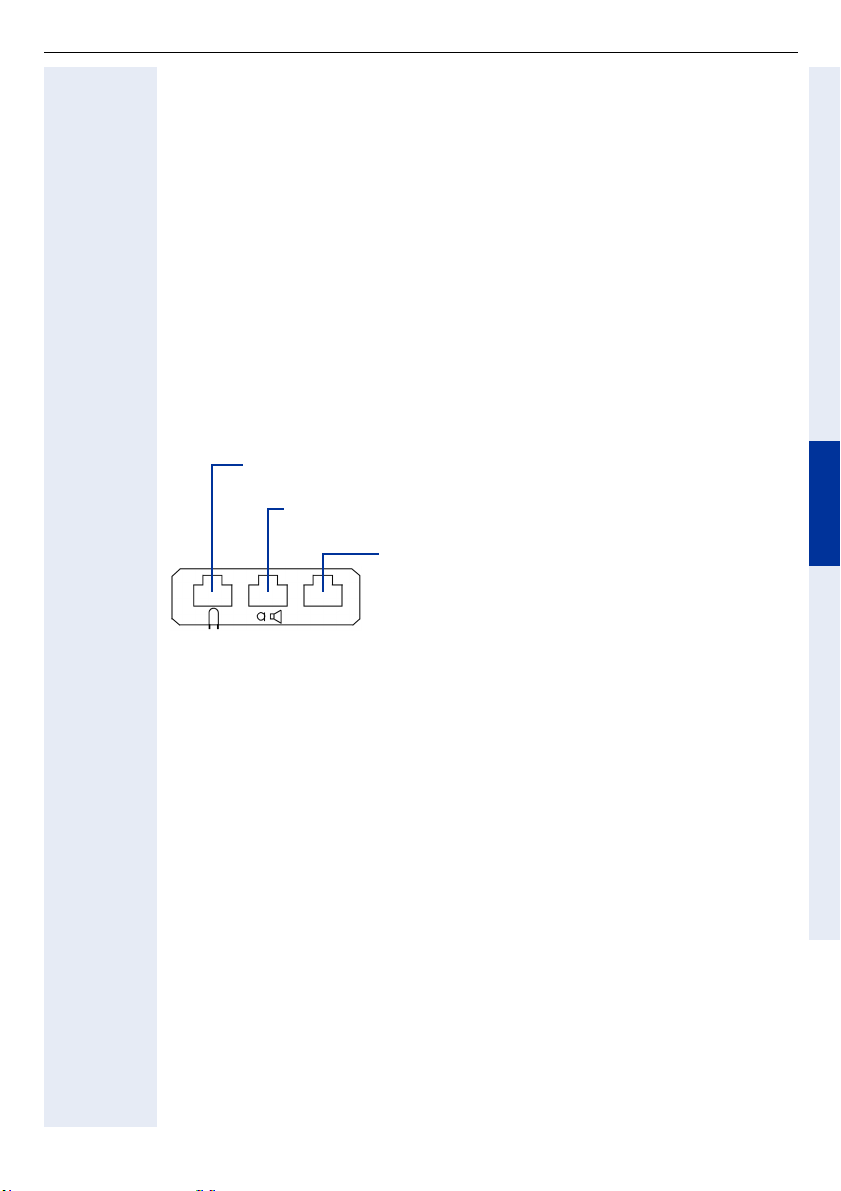
optiPoint acoustic adapter
head
optiPoint acoustic adapter
Veiligheidvoorschriften
De optiPoint-toestellen en adapters voldoen aan de geldende eisen met betrekking tot conformiteit en veiligheid (CE).
• Stel de telefoontoestellen niet bloot aan direct zonlicht of andere warmtebronnen.
• Stel de telefoontoestellen niet op in een vochtige omgeving en zorg ervoor
dat er geen vloeistoffen in de toestellen kunnen binnendringen.
• Steek geen voorwerpen in de toestelopeningen.
Toepassingsmogelijkheden
De acoustic adapter kan aan onderstaande telefoons worden aangesloten:
optiPoint 600 office, optiPoint 500 advance/standard/basic,
optiPoint 420 advance/standard, optiPoint 410 advance/standard.
De acoustic adapter heeft drie aansluitingen voor:
set (draadgebonden 121TR9-5/draadloos 121TR9-5*)
aansluiting op miniwestern 8/8
actieve luidsprekerbox en elektret microfoonaansluiting
op miniwestern 8/8 via Y- k a b e l (L36453-Z5-C199)
2 contacten voor bijv. een extra oproepsignaal (24 V
AC/60 V DC, 5 W) en een bezetlamp of deuropener
Aansluiting op miniwestern 6/6, galvanisch gescheiden
DeutschEnglishFrançaisNederlandsItalianoEspañolPortuguês
Leveringsomvang
• 1 optiPoint acustic adapter
Montage
Voor de montage zie ook uitvouwpagina 3 (pos. t/m ).
1. Koppel de aansluitkabel van het optiPoint-toestel los.
2. Plaats de optiPoint met de toetsen naar beneden op een zachte ondergrond.
3. Houd de adapter met de stekerverbinding naar beneden en bevestig hem
in één van beide inbouwplaatsen aan de onderzijde van het toestel door de
twee vergrendelnokjes in de beide sleuven te schuiven.
4. Druk de adapter met de stekerverbinding voorzichtig in de contactstrook tot
hij vastklikt .
5. Op de drie aansluitingen aan de achterzijde van de acoustic adapter kunt u
nu de additionele apparatuur aansluiten (met symbolen aangeduid).
6. Sluit de aansluitkabel van het optiPoint-toestel weer aan.
Het optiPoint-telefoon en het adapter zijn nu gereed om in bedrijf te worden genomen.
85
Page 86

optiPoint analog adapter
optiPoint analog adapter
Veiligheidvoorschriften
De optiPoint-toestellen en adapters voldoen aan de geldende eisen met betrekking tot conformiteit en veiligheid (CE).
• Stel de telefoontoestellen niet bloot aan direct zonlicht of andere warmtebronnen.
• Stel de telefoontoestellen niet op in een vochtige omgeving en zorg ervoor
dat er geen vloeistoffen in de toestellen kunnen binnendringen.
• Steek geen voorwerpen in de toestelopeningen.
Toepassingsmogelijkheden
De analoge adapter kan op de volgende toestellen worden aangesloten:
optiPoint 600 office, optiPoint 500 advance/standard/basic.
Met de analoge adapter heeft u de mogelijkheid, een additioneel telefoontoestel, faxapparaat, modem (bijv. PC met geïntegreerde modemkaart) of antwoordapparaat met analoge interface en TDK-kiesmethode aan te sluiten.
Om een analoog telefoontoestel aan te kunnen sluiten, heeft de analoge adapter
een externe stekertransformator nodig.
Per U
Leveringsomvang
• 1 optiPoint analog adapter
-toestelaansluiting is slechts één analoge adapter toegestaan.
P0/E
86
Montage
Voor de montage zie ook uitvouwpagina 3 (pos. t/m ).
1. Koppel de aansluitkabel van het optiPoint-toestel los.
2. Plaats de optiPoint met de toetsen naar beneden op een zachte ondergrond.
3. Houd de adapter met de stekerverbinding naar beneden en bevestig hem
in één van beide inbouwplaatsen aan de onderzijde van het toestel door de
twee vergrendelnokjes in de beide sleuven te schuiven.
4. Druk de adapter met de stekerverbinding voorzichtig in de contactstrook tot
hij vastklikt .
5. Via de 6-polige aansluiting aan de achterzijde van de analoge adapter kunt u
nu een analoog toestel aansluiten (a/b op pin 3 en 4).
6. Sluit de aansluitkabel van het optiPoint-toestel weer aan.
Het optiPoint-telefoon en het adapter zijn nu gereed om in bedrijf te worden genomen.
Page 87

optiPoint ISDN adapter
optiPoint ISDN adapter
Veiligheidsvoorschriften
De optiPoint-toestellen en adapters voldoen aan de geldende eisen met betrekking tot conformiteit en veiligheid (CE).
• Stel de telefoontoestellen niet bloot aan direct zonlicht of andere warmtebronnen.
• Stel de telefoontoestellen niet op in een vochtige omgeving en zorg ervoor
dat er geen vloeistoffen in de toestellen kunnen binnendringen.
• Steek geen voorwerpen in de toestelopeningen.
Toepassingsmogelijkheden
De ISDN-adapter kan op de volgende toestellen worden aangesloten:
optiPoint 600 office, optiPoint 500 advance/standard/basic.
Met de ISDN-adapter wordt een ISDN S
aansluiting van ISDN-toestellen met een S
De ISDN-toestellen met S
ken. De aansluiting bevindt zich aan de achterzijde van de adapter.
Per U
-toestelaansluiting is slechts één ISDN-adapter toegestaan.
P0/E
-interface dienen over een eigen voeding te beschik-
0
Inhoud van de verpakking
• 1 optiPoint ISDN adapter
-basisaansluiting gerealiseerd voor de
0
-interface.
0
DeutschEnglishFrançaisNederlandsItalianoEspañolPortuguês
Montage
Voor de montage zie ook uitvouwpagina 3 (pos. t/m ).
1. Aansluitsnoer van de optiPoint-telefoon verwijderen.
2. Het telefoon omgekeerd met het toetsenbord naar onderen op een zachte
onderlegger leggen.
3. De adapter wordt in één van de beide slots aan de onderkant van het toestel gemonteerd. Schuift u de beide stekkers van de adapter in de beide
slots van het toestel.
4. De adapter vervolgens in de richting van de pijl niet te krachtig naar beneden drukken totdat deze zich volledig in de slots bevindt.
5. Op de ISDN-adapter kunnen twee ISDN-toestellen op een maximaal 150 m
lange S0-bus worden aangesloten. De S0-bus moet aan het einde met twee
Ω
100 -weerstanden worden afgesloten. De ISDN-toestellen kunnen echter
niet gelijktijdig worden gebruikt, omdat er slechts één B-kanaal ter beschikking staat.
6. Sluit de aansluitkabel van het optiPoint 500-toetsel weer aan.
Het optiPoint-telefoon en het adapter zijn nu gereed om in bedrijf te worden genomen.
87
Page 88

optiPoint phone adapter
optiPoint phone adapter
Veiligheidvoorschriften
De optiPoint-toestellen en adapters voldoen aan de geldende eisen met betrekking tot conformiteit en veiligheid (CE).
• Stel de telefoontoestellen niet bloot aan direct zonlicht of andere warmtebronnen.
• Stel de telefoontoestellen niet op in een vochtige omgeving en zorg ervoor
dat er geen vloeistoffen in de toestellen kunnen binnendringen.
• Steek geen voorwerpen in de toestelopeningen.
Toepassingsmogelijkheden
De phone adapter kan op de volgende optiPoint-toestellen worden aangesloten:
optiPoint 600 office, optiPoint 500 advance/standard/basic.
Met de phone adapter heeft u de mogelijkheid, zonder speciale aansluitkabel
een tweede optiPoint-toestel aan te sluiten.
De aansluiting bevindt zich aan de achterzijde van de adapter.
Per U
Leveringsomvang
optiPoint phone adapter
-toestelaansluiting is slechts één phone adapter toegestaan.
P0/E
88
Montage
Voor de montage zie ook uitvouwpagina 3 (pos. t/m ).
1. Koppel de aansluitkabel van het optiPoint-toestel los.
2. Plaats de optiPoint met de toetsen naar beneden op een zachte ondergrond.
3. Houd de adapter met de stekerverbinding naar beneden en bevestig hem
in één van beide inbouwplaatsen aan de onderzijde van het toestel door de
twee vergrendelnokjes in de beide sleuven te schuiven.
4. Druk de adapter met de stekerverbinding voorzichtig in de contactstrook tot
hij vastklikt .
5. Via de 6-polige aansluiting aan de achterzijde van de phone adapter kunt u nu
een tweede optiPoint-toestel (alle typen) aansluiten.
6. Sluit de aansluitkabel van het optiPoint-toestel weer aan.
Het optiPoint-telefoon en het adapter zijn nu gereed om in bedrijf te worden genomen.
Page 89
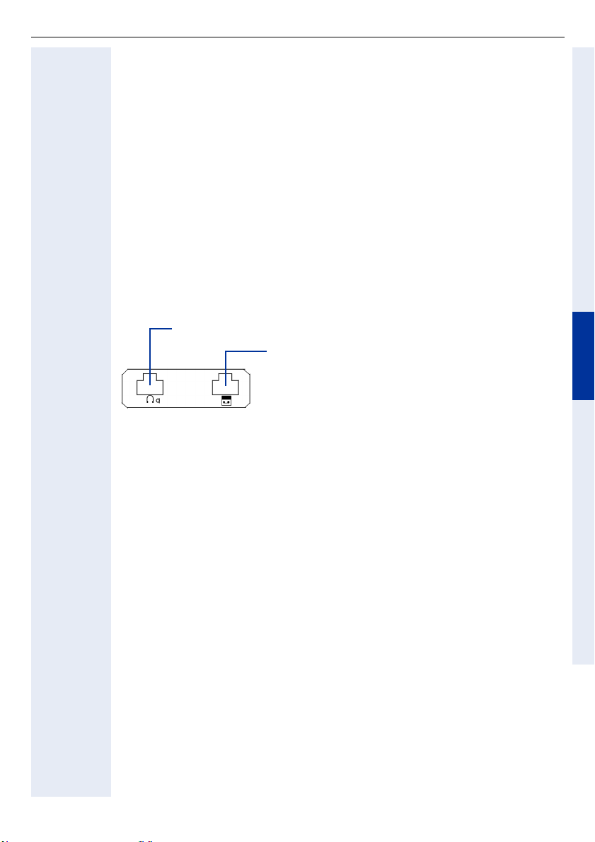
optiPoint recorder adapter
optiPoint recorder adapter
Veiligheidsvoorschriften
De optiPoint-toestellen en adapters voldoen aan de geldende eisen met betrekking tot conformiteit en veiligheid (CE).
• Stel de telefoontoestellen niet bloot aan direct zonlicht of andere warmtebronnen.
• Stel de telefoontoestellen niet op in een vochtige omgeving en zorg ervoor
dat er geen vloeistoffen in de toestellen kunnen binnendringen.
• Steek geen voorwerpen in de toestelopeningen.
Toepassingsmogelijkheden
De recorder adapter kan aan de onderstaande telefoons worden aangesloten:
optiPoint 600 office, optiPoint 500 advance/standard/basic,
optiPoint 420 advance/standard, optiPoint 410 advance/standard.
De recorder adapter heeft drie aansluitingen voor:
Meeluisterschelp op 4-polige RJ11-connector
Opnameapparatuur (recorder) op 6-polige RJ11-connector
Inhoud van de verpakking
• 1 optiPoint recorder adapter
DeutschEnglishFrançaisNederlandsItalianoEspañolPortuguês
Montage
Voor de montage zie ook uitvouwpagina 3 (pos. t/m ).
1. Aansluitsnoer van de optiPoint-telefoon verwijderen.
2. Het telefoon omgekeerd met het toetsenbord naar onderen op een zachte
onderlegger leggen.
3. De adapter wordt in één van de beide slots aan de onderkant van het toestel gemonteerd. Schuift u de beide stekkers van de adapter in de beide
slots van het toestel.
4. De adapter vervolgens in de richting van de pijl niet te krachtig naar beneden drukken totdat deze zich volledig in de slots bevindt.
5. Sluit de meeluisterschelp en de opnameapparatuur aan op de daarvoor gemarkeerde adapterbus(sen).
6. Het aansluitsnoer weer op de optiPoint-telefoon aansluiten.
Het optiPoint-telefoon en het adapter zijn nu nu gereed om in bedrijf te worden
genomen.
89
Page 90

Nederland
Toebehoren
Actieve luidsprekerbox
s
Actieve luidsprekerbox
Veiligheidsvoorschriften
• Stel de telefoontoestellen niet bloot aan direct zonlicht of andere warmtebronnen.
• Stel de telefoontoestellen niet op in een vochtige omgeving en zorg ervoor
dat er geen vloeistoffen in de toestellen kunnen binnendringen.
• Steek geen voorwerpen in de toestelopeningen.
Toepassingsmogelijkheden
De actieve luidsprekerbox kan los of samen met de extra microfoon via
optipoint acoustic adapter (S30817-K7110-B508) en Y-Kabel (L36453-Z5-C199)
op de volgende toestellen worden aangesloten:
optiPoint 600 office, optiPoint 500 advance/standard/basic,
optiPoint 420 advance/standard, optiPoint 410 advance/standard.
Algemeen
De actieve luidsprekerbox verbetert de geluidskwaliteit bij meeluisteren. Zodra
de luidsprekerbox wordt aangesloten, wordt de interne luidspreker van de telefoon zelf uitgeschakeld. Als u de luidsprekertoets op de telefoon indrukt, verloopt het meeluisteren alleen via de luidsprekerbox.
De luidsprekerbox kan vrijstaand worden opgesteld, maar kan bijv. ook op een
montageframe aan de wand worden gemonteerd.
90
Inhoud van de verpakking
• 1 actieve luidsprekerbox met aansluitkabel (2 m).
• 1 netadapter 230 V AC/22 V AC met aansluitkabel (2 m).
• 1 kunststof houder en 1 bevestigingsschroef voor wandmontage.
• 1 montagehandleiding.
Page 91

Actieve luidsprekerbox
Ingebruikname
Let op!
Gebruik alleen de meegeleverde netadapter!
Voorwaarde: de betreffende adapter is al volgens voorschrift in de telefoon ingebouwd.
1. Draaiknop aan de voorzijde van de luidsprekerbox zo ver mogelijk naar links
draaien (minimaal volume).
2. Miniwestern-steker 8/8 van de Y-Kabel in de connector van de acoustic adapters steken.
3. Steker van de aansluitkabel in de connector van de Y-kabel steken.
4. Haakse steker van de meegeleverde netadapter in de ronde connector op
de onderzijde van de luidsprekerbox steken.
5. Luidsprekerbox niet in de buurt van telefoon of extra microfoon opstel-
len. Dit om akoestische terugkoppelingseffecten (z.g. rondzingen) te voorkomen.
6. Netadapter in de 230-V-contactdoos steken.
Het standby-lampje (LED) aan de voorzijde van de luidsprekerbox licht op.
7. Basisvolume instellen:
Via de draaiknop van de luidsprekerbox wordt alleen het basisvolume ingesteld, dat aan de ruimtelijke omstandigheden kan worden aangepast, maar
vervolgens niet meer veranderd mag worden.
Het instellen gaat als volgt:
• Volume van de telefoon-luidspreker zo zacht mogelijk zetten en opslaan,
zie gebruiksaanwijzing telefoon.
• Met de toets „Luidspreker“ meeluisterfunctie inschakelen.
• Bijvoorbeeld met kiestoon of tijdens een gesprek het basisvolume (normaal
volume) met de draaiknop van de luidsprekerbox instellen.
DeutschEnglishFrançaisNederlandsItalianoEspañolPortuguês
Bediening
De meeluisterfunctie kunt u met de toets „Luidspreker“ van de telefoon in- en
uitschakelen. Het actuele volume van de luidsprekerbox mag u alleen met de
toetsen „+“ en „–“ van de telefoon veranderen.
91
Page 92

Actieve luidsprekerbox
Wandmontage
1. Verwijder aan de onderzijde van de luidsprekerbox het achterste voetje
(nop).
2. Druk de meegeleverde kunststof houder in de opening.
3. Met de kunststof houder en de meegeleverde schroef kan de luidspreker-
box bijv. staand op een montageframe (niet standaard meegeleverd) worden
bevestigd.
Let op: kunststof houder en schroef zijn niet geschikt voor rechstreekse (hangende) wandmontage!
Technische gegevens
Stroomvoorziening: Alleen via meegeleverde netadapter:
Vermogen versterker: 7 watt
Frequentiebereik: 100 Hz–16 kHz
Ingangsgevoeligheid: 250 mV (bij volledige uitsturing)
Impedantie: 10 k
Aansluitkabel: 2 m; met Miniwestern-steker 4/4
Afmetingen: 160 x 98 x 95 (H x B x D, in mm)
Gewicht: circa 500 g
L30460-X1325-X; voor GB:L30460-X1325-X1
230 V AC +6%/–10% / 22 V AC; 50 Hz;
Aansluitkabel 2 m; met haakse steker
Ω
92
Page 93

Extra microfoon
Extra microfoon
Veiligheidsvoorschriften
• Stel de telefoontoestellen niet bloot aan direct zonlicht of andere warmtebronnen.
• Stel de telefoontoestellen niet op in een vochtige omgeving en zorg ervoor
dat er geen vloeistoffen in de toestellen kunnen binnendringen.
• Steek geen voorwerpen in de toestelopeningen.
Toepassingsmogelijkheden
De extra microfoon kan los of samen met de actieve actieve luidsprekerbox via
optipoint acoustic adapter (S30817-K7110-B508) en Y-kabel (L36453-Z5-C199)
op de volgende toestellen worden aangesloten:
optiPoint 600 office, optiPoint 500 advance/standard/basic,
optiPoint 420 advance/standard, optiPoint 410 advance/standard.
Algemeen
De extra microfoon verbetert de spraakkwaliteit bij handsfree telefoneren, bijv.
aan een bespreektafel. Bij aansluiting van de extra microfoon wordt de interne
microfoon van de telefoon zelf uitgeschakeld. Wanneer u de toets „Luidspreker“ op de telefoon indrukt, vindt het handsfree gesprek uitsluitend via de extra
microfoon plaats. De microfoon kan vrijstaand worden opgesteld. De optimale
spreekafstand bedraagt 50 cm.
DeutschEnglishFrançaisNederlandsItalianoEspañolPortuguês
Inhoud van de verpakking
• 1 extra microfoon met aansluitkabel (2 m)
• 1 montagehandleiding
Ingebruikname
1. Miniwestern-steker 8/8 van de Y-kabel in de connector van de acoustic adapter steken.
2. Steker van de aansluitkabel in de connector van de Y-kabel steken.
3. Extra microfoon niet richting telefoon of luidsprekerbox opstellen, ten-
einde akoestische terugkoppeling (z.g. rondzingen) te voorkomen.
93
Page 94

Extra microfoon
Bediening
De handsfree-functie wordt via de toets „Luidspreker“ van de telefoon in- en uitgeschakeld. De statusindicatie (LED) bovenaan de microfoon licht op, wanneer
de microfoon ingeschakeld is.
Door het indrukken van de mute-toets kan de microfoon eventueel tijdelijk worden uitgeschakeld – LED uit, bijv. bij ruggespraak). Zodra de mute-toets wordt
losgelaten, is de microfoon weer actief.
Technische gegevens
Akoestische werking: Drukontvanger
Frequenzbereich: 100 Hz–7 kHz
Karakteristiek: Nier
Uitgangsimpedantie: 10 k
Voedingsspanning: 3,8 V–6 V DC;
Stroomopname: max. 6 mA bij 3,8 V en LED aan
Aansluitkabel: 2 m; met Miniwestern-steker 4/4
Afmetingen: 25 x 68 x 77 (H x B x D, in mm)
Ω
Voeding van adapter via aansluitkabel
94
Page 95

optiPoint Conference Kit
optiPoint Conference Kit
Algemeen
De optiPoint Conference Kit verbetert de handfreekwaliteit bij telefonische conferenties, met name in conferentieruimten met gespreksdeelnemers die zich
verspreid in de ruimte bevinden. Bij maximale configuratie kunnen 2 conferentie-luidsprekerboxen en 8 conferentiemicrofoons
dekking worden aangesloten.De conferentiemicrofoons beschikken hierbij elk
over eigen versterker- en besturingselektronica, die ervoor zorgt dat alleen recent gebruikte microfoons actief zijn, om op die manier het geluidsniveau (ruimte-echo) zoveel mogelijk te scheiden van het directe geluidssignaal.
Zowel de gevoeligheid van de microfoons als ook het achtergrondgeluidsniveau
kan op de verdelermodules aangepast aan de bestaande ruimtelijke akoestiek
worden ingesteld,
Bij gesprekspauzes (en dus uitgeschakelde microfoons) kan bij bijgeschakelddeelnemers nu niet de indruk ontstaan dat de verbinding verbroken is.
Elke microfoon beschikt over een mute-toets, waarmee alle conferentiemicrofoons kunnen worden uitgeschakeld.
De voeding van de optiPoint Conference Kit vindt plaats via een eigen netadapter.
Veiligheidsvoorschriften
• Stel de telefoontoestellen niet bloot aan direct zonlicht of andere warmtebronnen.
• Stel de telefoontoestellen niet op in een vochtige omgeving en zorg ervoor
dat er geen vloeistoffen in de toestellen kunnen binnendringen.
• Steek geen voorwerpen in de toestelopeningen.
1
voor optimale akoestische
DeutschEnglishFrançaisNederlandsItalianoEspañolPortuguês
[1] Daarnaast kan er een draadloze microfoon worden toegepast.
95
Page 96
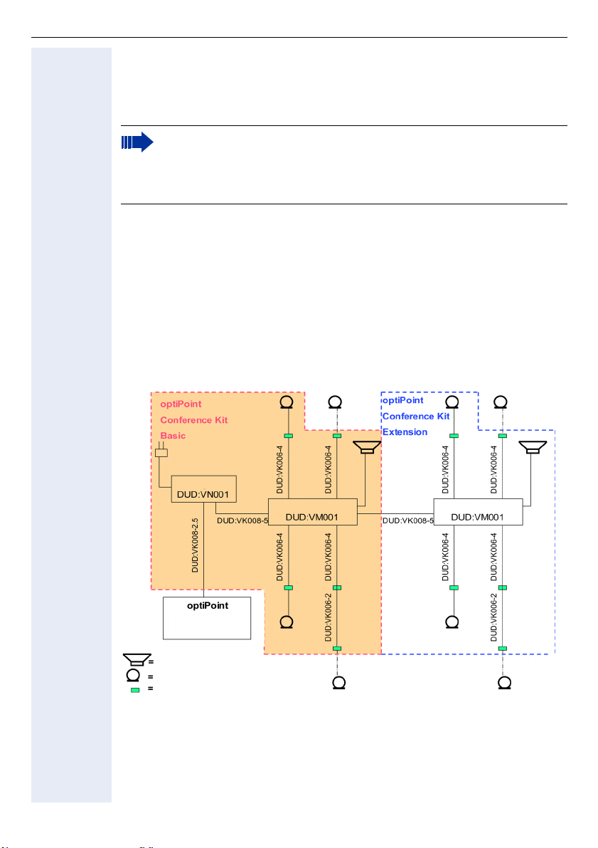
optiPoint Conference Kit
Toepassingsmogelijkheden
De optiPoint Conference Kit Basic en Extension worden met de optiPoint
acoustic adapter (S30817-K7110-B508) als randapparatuur aangesloten op de
optiPoint-telefoons.
Voor de optiPoint Conference Kit Basic en Extension zijn uitsluitend de standaard meegeleverde (of separaat bestelbare) conferentie-luidsprekerboxen
en -microfoons toegestaan. Deze zijn speciaal ontworpen voor de
optiPoint Conference Kit.
Montage/Ingebruikname
Voorwaarde: de optiPoint acoustic adapter is al volgens voorschrift in de bestaande optiPoint-telefoon ingebouwd.
Op het schema hieronder is te zien hoe de diverse componenten op elkaar zijn
aangesloten.
Let op: de Y-kabel (L36453-Z5-C199) voor rechtstreekse aansluiting van
de actieve luidsprekerbox (L30460-X1278-X) en de extra microfoon
(L30460-X1279-X) hebt u hiervoor niet nodig. De genoemde actieve luidsprekerboxen en extra microfoons voor directe aansluiting kunnen niet
op de optiPoint Conference Kit worden gebruikt.
96
Netadapter
Verdelermodule 1
met
acoustic Adapter
conferentie-luidsprekerbox DUD:VL001
conferentie-microfoon DUD:VD001
connector DUD:VB002
Verdelermodule 2
Optioneel stropdasmicrofoon
DUD:VE001
Page 97

optiPoint Conference Kit
Montage
De optiPoint Conference Kit Basic wordt standaard geleverd met een netadapter, een verdelermodule, een conferentie-luidsprekerbox, twee conferentiemicrofoons alsmede kabels en montagemateriaal (zie leveringsomvang). De montageset bevat ook de aansluitkabels voor nog eens twee optionele microfoons
(naar keuze ook als stropdasmicrofoon leverbaar), alsmede twee extra aansluitkabels en connectoren voor het geval de microfoonaansluitingen moeten worden verlengd.
Met uitzondering van de netadapter en aansluitkabels voor de optiPoint acoustic
Adapter heeft de optiPoint Conference Kit Extension dezelfde componenten.
De aansluitkabel „DUD:VK008-2,5“voor de aansluiting van de optiPoint acoustic
Adapter (symbool voor luidspreker/micro) op de netadapter heeft gecodeerde
stekers en mag uitsluitend worden gebruikt voor de verbinding telefoonnetadapter (rood gemarkeerd).
Let op: de kabel mag onder geen beding worden aagesloten op de uitgangsconnector van de adapter naar de verdelermodules. Voor de verbinding netadapter - verdelermodule resp. verdelermodule 1 - verdelermodule 2 dient de 5-meter-kabel „DUD:VK008-5“ te worden gebruikt.
Voor een onzichtbare opbouw van het systeem hebben verdelermodules en
netadapter aan de zijkant bevestigingselementen, waarmee ze eventueel onder
tafel kunnen worden bevestigd, mocht er geen dubbele vloer aanwezig zijn. De
in de montageset opgenomen en van montagegaten voorziene connectoren
6/4 zijn bedoeld voor de aansluiting van de conferentie-microfoons. De connectoren dienen op een voor de hand liggende plek in de buurt van de zitplaats van
de gesprekspartners onder het tafelblad te worden aangebracht en verbinden
enerzijds de aansluitkabel „DUD:VK006-4“ met de verdelermodule, anderzijds
de microfoon.
De aansluitkabels „DUD:VK006-4“ (verdelermodule naar connector) kunnen zonodig worden verlengd met de extra kabels „DUD:VK006-2“ uit de montageset
en extra connectoren.
DeutschEnglishFrançaisNederlandsItalianoEspañolPortuguês
Let op: alleen de kabels uit de montageset mogen worden gebruikt.
De conferentie-luidsprekerbox wordt met de gemarkeerde connector in de verdelermodule verbonden. Een extra netadapter voor de actieve luidspreker is niet
nodig, omdat de voeding via de module-netdapter plaatsvindt.
De meegeleverde, zelfklevende kabelklemmen dienen voor de bevestiging van
de toevoerkabels onder het tafelblad. Doordat alle componenten via connectoren met elkaar verbonden zijn, kan het systeem variabel worden ingezet en kan
het (bijv. bij herschikking van de conferentietafels) probleemloos en in korte tijd
aan de nieuwe omstandigheden worden aangepast.
Na complete installatie wordt de netadapter met 230V netspanning verbonden
(landspecifieke stekernetadapters dient u zelf bij de hand te houden).
De bedrijfsindicatie (LED) op luidsprekerbox en microfoons licht op.
97
Page 98

optiPoint Conference Kit
Instellingen
Om storende akoestische invloeden (terugkoppeleffect, het z.g. rondzingen) van
de luidspreker op de microfoons te vermijden, mag de luidsprekerbox niet in de
richting van een microfoon worden geplaatst.
Via de volumeregelaar van de luidsprekerbox wordt alleen het basisvolume ingesteld, dat aan de ruimtelijke omstandigheden kan worden aangepast, maar
vervolgens niet meer veranderd mag worden.
Voordat u overgaat tot de fijnafstelling van dit basisvolume, zet u de luidspreker
van de telefoon eerst zo zacht mogelijk en slaat dit volume op (zie gebruiksaanwijzing optiPoint).
Na het indrukken van de toets „luidspreker“ op de telefoon kan door de kiestoon
of tijdens een gesprek het basisvolume via de draaiknop van de luidsprekerbox
worden ingesteld.
Bij de Extension-conferentie luidsprekerbox kiest u een identiek basisvolume.
Latere aanpassingen van het volume tijdens conferenties mogen alleen nog
maar via de toetsen u en v van de optiPoint-telefoon worden uitgevoerd.
Via de regelaar "Micro sens." aan de voorzijde van de verdelermodule kan de ge-
voeligheid (drempelwaarde) van de conferentiemicrofoons worden ingesteld.
De 4 LED's zijn toegewezen aan de microfoons en dienen ter controle van de
instelling.
Bij een optimale instelling licht alleen de LED op van de microfoon die net op dat
moment in gebruik is, en bij gesprekspauzes horen alle microfoons te worden
uitgeschakeld. Om ervoor te zorgen dat voor bijgeschakelde conferentiedeelnemers niet de indruk ontstaat dat de verbinding onderbroken is, is het mogelijk
om een restwaarde van het omgevingsgeluid als achtergrondgeluid vast te houden. Dit gebeurt met de regelaar "Room noise" op de voorzijde van de verdelermodule. Alle instellingen dienen met een paar gesprekspogingen te worden aangepast aan de geldende ruimtelijke omstandigheden. De optimale
instellingswaarden moeten op beide verdelermodulen identiek worden gekozen.
98
Aan het begin van een conferentie en bij plotselinge veranderingen van
de ruimtelijke akoestiek heeft de optiPoint Conference Kit in combinatie
met de full-duplex handsfreefunctie van de optiPoint-toestellen altijd enkele seconden nodig om de kwaliteit van de geluidstransmissie optimaal
aan te passen aan de veranderde omstandigheden. Dit is om technische
redenen alleen mogelijk, wanneer op zulke momenten liefst maar één
conferentiedeelnemer tegelijk spreekt. In de menu-instellingen van de
optiPoint-handsfreefunctie (zie gebruiksaanwijzing optiPoint) vindt u nog
een andere optimaliseringsmogelijkheid om de handsfreekwaliteit van
een gedempte, normale of galmende ruimtelijke akoestiek aan te passen.
Page 99

optiPoint Conference Kit
Technische gegevens
Netadapter Primair: 230V AC, 30 VA
Secundair:24 V DC gestabiliseerd
5 V DC gestabiliseerd
Stroomopname: 60mA primair
Materiaal: PS (Polystorol)
Beschermingsklasse: IP 40
Afmetingen: 150 x 80 x 55 (L x B x H in mm)
Verdelermodule 4 conferentie-microfooningangen met nageschakelde versterker
Conferentieluidspreker
Conferentiemicrofoon
Conferentiestropdasmicrofoon
en separaat automatisch uitschakelmechanisme (gekoppeld aan
geluidsniveau)
Mute-uitschakelelektronica voor alle kanalen
1 luidsprekerboxaansluiting met voeding
Uitgangsconnector voor 2e verdelermodule of radiomicrofoon
Instelregelaar voor gevoeligheid van de microfoons
Instelregelaar voor achtergrondgeluidsniveau
Versterkervermogen: 7 watt
Frequentiebereik: 100 Hz-16 kHz
LF-ingangsimpedantie: 10 KOhm
Stroomopname: 30/170mA (Rust/Last)
Aansluitkabel: 2 m met miniwesternsteker
Afmetingen: 160 x 98 x 95 (H x B x D in mm)
Kleur: mangaan
Gewicht: ca. 450 g
Akoestische werkwijze: drukontvanger
Frequentiebereik: 100 Hz - 7 kH
Karakteristiek: nier
Uitgangsimpedantie: 10 KOhm
Voedingsspanning: 5 V DC
Stroomopname: 6 mA
Aansluitkabel: 0,80 m
Afmetingen: 25 x 68 x 77 (H x B x D in mm)
Kleur: mangaan
Akoestische werkwijze: drukontvanger
Frequentiebereik: 100 Hz - 7 kHz
Karakteristiek: nier
Uitgangsimpedantie: 10 KOhm
Voedingsspanning: 5 V DC
Stroomopname: 4 mA
Aansluitkabel: 1,40 m
Afmetingen behuizing: 65 x 46 x 16 mm
(microfoongedeelte: 20 x 13 mm)
DeutschEnglishFrançaisNederlandsItalianoEspañolPortuguês
99
Page 100

optiPoint Conference Kit
Over de CE-compatibiliteit
Let op:
Luidspreker en conferentie-microfoon uitsluitend met
optiPoint Conference Kit gebruiken.
Vóór ingebruikname de schakelaar van de stropdasmicrofoon op "ON"
zetten.
This equipment complies with the requirements of the EU directives 99/5/EEC:
EN 60950: 2000 Safety
EN 55022: 1998 Class B EMC, Emission ITE Residential
Environment
EN 55024: 1998 EMC, Immunity ITE Residential
Environment
100
 Loading...