

Page 1

SINUMERIK 840Di sl/840D sl/840D
HMI-Advanced
Operating Manual
Introduction
Operator Components/
Operating Sequences
Example of Operation
Machine
Parameters
Program
1
2
3
4
5
6
Services
Diagnostics
operating area
Valid for
Control
SINUMERIK 840D sl / 840 DE sl
SINUMERIK 840Di sl / 840 DiE sl
SINUMERIK 840D powerline / 840DE powerline
Software Software version
HMI-Advanced 7.5
Commissioning
operating area
Maintenance
Appendix
7
8
9
10
A
01/2008 Edition
Page 2

SINUMERIK® Documentation
Printing history
Brief details of this edition and previous editions are listed below.
The status of each version is indicated by the code in the "Remarks" columns.
Status code in the "Remarks" column:
A .... New documentation.
B .... Unrevised reprint with new order number.
C .... Revised edition with new status.
Edition Order No. Remarks
SW assignment
02.01 6FC5298-6AF00-0BP0 C
11.02 6FC5298-6AF00-0BP2 C
03.04 6FC5298-6AF00-0BP2 C NCU system software 7
08/2005 6FC5398-2AP10-0BA0 C HMI-Advanced V 7.1
01/2006 6FC5398-2AP10-1BA0 C HMI-Advanced V 7.2 SP1
11/2006 6FC5398-2AP10-2AA0 C
01/2008 6FC5398-2AP10-
3BA0
C
Registered trademarks
All names with the protective right label ® are registered trademarks of the Siemens AG. The
other product and system names in this document may be registered trademarks of their
respective companies and must be treated accordingly. .
Disclaimer of liability
We have checked that the contents of this document correspond to the hardware and
software described. Since deviations cannot be precluded entirely, we cannot guarantee full
agreement. The information contained in this document is, however, reviewed regularly and
any necessary changes will be included in the next edition.
Siemens AG
Automation and Drives
Postfach 48 48
90437 NUREMBERG
GERMANY
Order No. 6FC5398-2AP10-
3BA0
Copyright © Siemens AG 1995 - 2008
Subject to change without prior notice
Page 3

01/2008 Preface
Layout of manual
0
Preface
SINUMERIK
Documentation
Target readership of this
documentation
Standard scope
0
The SINUMERIK documentation is organized in 3 parts:
• General documentation
• User documentation
• Manufacturer/Service Documentation
An overview of publications, which is updated on a monthly basis and
provides information about the language versions available, can be
found on the Internet at:
http://www.siemens.com/motioncontrol
Follow the menu items "Support" "Technical Documentation"
"Overview of Publications".
The Internet version of DOConCD (DOConWEB) is available at:
http://www.automation.siemens.com/doconweb
Information about training courses and FAQs (Frequently Asked
Questions) can be found in internet under:
http://www.siemens.com/motioncontrol
This manual is intended for machine-tool users. The document
describes in detail all the technical information an operator needs to
operate the SINUMERIK 840Di sl/840D sl/840D controls.
This Operator’s Guide describes only the functionality of the standard
version. Extensions or changes made by the machine manufacturer
are documented by the machine manufacturer.
under menu item "Support"
Other functions not described in this documentation might be
executable in the control. This does not, however, represent an
obligation to supply such functions with a new control or when
servicing.
© Siemens AG 2008 All rights reserved.
SINUMERIK 840Di sl/840D sl/840D Operating Manual HMI-Advanced (BAD) - 01/2008 Edition iii
Questions on the manual
EC Declaration of
Conformity
If you have any questions about the documentation (suggestions,
corrections) please send
a fax or e-mail to the following address:
Fax: +49 (0) 9131 / 98 - 63315
E-mail: docu.motioncontrol@siemens.com
The EC Declaration of Conformity for the EMC Directive can be
viewed/downloaded from the Internet at:
http://support.automation.siemens.com
under the Product Order No. 15257461 or at the relevant branch
office of the A&D MC Division of Siemens AG.
Page 4
Preface 01/2008
Layout of manual
0
0
Hotline
Internet address
Safety information
Danger Indicates that death or severe personal injury will result if proper
Warning This warning notice indicates that death or severe personal injury can
If you have any questions, please contact the following hotline:
Europe and Africa time zone:
A&D Technical Support
Tel.: +49 (0) 180 / 5050 - 222
Fax: +49 (0) 180 / 5050 - 223
Internet: http://www.siemens.de/automation/support-request
E-mail: adsupport@siemens.com
Asia and Australia time zone
A&D Technical Support
Tel.: +86 1064 719 990
Fax: +86 1064 747 474
Internet: http://www.siemens.com/automation/support-request
E-mail: adsupport@siemens.com
America time zone
A&D Technical Support
Tel.: +1 423 262 2522
Fax: +1 423 262 2289
Internet: http://www.siemens.com/automation/support-request
E-mail: adsupport@siemens.com
http://www.siemens.com/motioncontrol
This Manual contains information which you should carefully observe
to ensure your own personal safety and the prevention of material
damage. The notices referring to your personal safety are highlighted
in the manual by a safety alert symbol, notices referring to property
damage only, have no safety alert symbol. Depending on the hazard
level, warnings are indicated in a descending order as follows:
precautions are not taken.
result if proper precautions are not taken.
iv SINUMERIK 840Di sl/840D sl/840D Operating Manual HMI-Advanced (BAD) - 01/2008 Edition
© Siemens AG 2008 All rights reserved.
Page 5

01/2008 Preface
Layout of manual
0
Caution
Caution
Notice
Qualified persons
Correct use
Warning
0
means that there can be slight physical injury if the corresponding
safety measures are not followed.
without a safety alert symbol, indicates that property damage may
result if proper precautions are not taken.
This means that an undesirable result or an undesirable state can
occur if the information is ignored.
If multiple levels of hazards can occur, the warning is always
displayed with the highest possible level. If a warning with a warning
triangle is to indicate physical injury, the same warning may also
contain information about damage to property.
The associated device/system may only be set-up and operated in
conjunction with this documentation. The device/system must be
commissioned and operated by qualified personnel only. Qualified
personnel as referred to in the safety guidelines in this documentation
are those who are authorized to start up, earth and label units,
systems and circuits in accordance with the relevant safety standards.
Please observe the following:
The device must only be used for the applications specified in the
catalog and in the technical description. The device must only be used
in conjunction with external devices and components recommended
or approved by Siemens. Correct, reliable operation of the product
required proper transport, storage, positioning and assembly, as well
as careful operation and maintenance.
© Siemens AG 2008 All rights reserved.
SINUMERIK 840Di sl/840D sl/840D Operating Manual HMI-Advanced (BAD) - 01/2008 Edition v
Page 6

Preface 01/2008
Layout of manual
0
0
Export versions
Function
840DE sl
840DE
840DiE sl
Helical interpolation 2D+6
(Basic version, no options)
Milling machining package
Five axis machining package
Handling transformation package
Multi-axis interpolation
(> 4 interpolating axes)
OA NCK compile cycles
Clearance control 1D/3D in position-control
1)
cycle
Synchronized actions 1)
(Basic version, no options)
Master-value coupling and curve table
interpolation
Sag compensation, multi-dimensional # #
Synchronized actions, stage 2
Electronic gear
1)
1)
− −
− −
− −
− −
− −
− −
− −
# #
# #
−
−
#
#
Electronic transfer
−
# Restricted functionality
− Function not possible
1) In the case of the SINUMERIK 840DE sl/840DE/840DiE powerline
export versions, the restricted functions are limited to "max. 4
interpolating axes“
#
vi SINUMERIK 840Di sl/840D sl/840D Operating Manual HMI-Advanced (BAD) - 01/2008 Edition
© Siemens AG 2008 All rights reserved.
Page 7

01/2008 Preface
Layout of manual
0
0
Structure of descriptions
All functions and operating options have been described according to
the same internal structure as far as this is meaningful and
practicable. The various levels of information have been organized
such that you can selectively access the information you need for the
task in hand.
1. Function
The theoretical section is primarily intended as learning material for
the NC entry-level user and includes important information to assist
the user to understand the operator functions.
You should work through the manual at least once to get an idea of
the operational scope and capability of your SINUMERIK control.
2. Sequence of operations
This section contains the sequence of keys required for operation at a
glance. If inputs have to be made at individual stages of the sequence
or if you require additional information, you will find this next to the key
illustrations.
3. Additional information
For safety reasons, some functions are disabled to protect them from
unauthorized access. The machine manufacturer can customize or
modify the described functionality. Please comply fully with the
instructions of the machine-tool manufacturer.
In this documentation, you will find this symbol with a reference to an
ordering data option. The described function can only run if the control
contains the designated option.
Notes This symbol appears in this documentation whenever it is necessary
to draw your attention to an important item of information.
References This symbol appears whenever specific information can be found in
other documentation.
A complete list of available literature is included in the Appendix of this
Operator’s Guide.
© Siemens AG 2008 All rights reserved.
SINUMERIK 840Di sl/840D sl/840D Operating Manual HMI-Advanced (BAD) - 01/2008 Edition vii
Page 8

Preface 01/2008
Layout of manual
0
0
Explanation of symbols:
Function
Sequence of operations
Additional information
Cross-references to other documentation or sections
Danger notices
Additional notes or background information
Ordering data option
Explanation
Description of syntax
Programming Examples
viii SINUMERIK 840Di sl/840D sl/840D Operating Manual HMI-Advanced (BAD) - 01/2008 Edition
© Siemens AG 2008 All rights reserved.
Page 9

01/2008 Contents
0
Contents
Introduction......................................................................................................1-17
1.1 Product overview ...................................................................................................... 1-18
1.2 Handling information................................................................................................. 1-19
1.3 Switching on/switching off the control....................................................................... 1-20
Operator Components/Operating Sequences...............................................2-23
2.1 Operator panel front..................................................................................................2-24
2.1.1 Keys on the operator panel front ..............................................................................2-24
2.1.2 Standard full keyboard.............................................................................................. 2-29
2.2 Machine control panel (MCP) ................................................................................... 2-30
2.2.1 EMERGENCY STOP button..................................................................................... 2-31
2.2.2 Operating modes and machine functions................................................................. 2-31
2.2.3 Feedrate control........................................................................................................ 2-33
2.2.4 Spindle control .......................................................................................................... 2-35
2.2.5 Key-operated switch .................................................................................................2-36
2.2.6 Program control ........................................................................................................ 2-37
0
2.3 SINUMERIK HT 8 ..................................................................................................... 2-39
2.4 Screen layout ............................................................................................................ 2-42
2.4.1 Displaying the control states..................................................................................... 2-42
2.4.2 Global machine status display.................................................................................. 2-43
2.4.3 Program control display ............................................................................................ 2-48
2.5 General operating sequences................................................................................... 2-50
2.5.1 Program overview and program selection................................................................ 2-50
2.5.2 Changing the menu window ..................................................................................... 2-51
2.5.3 Selecting a directory/file............................................................................................ 2-52
2.5.4 Editing inputs/values ................................................................................................. 2-53
2.5.5 Confirm/cancel input ................................................................................................. 2-54
2.5.6 Edit the part program in the ASCII editor.................................................................. 2-55
2.5.7 Switching over the channel....................................................................................... 2-61
2.5.8 Packet calculator....................................................................................................... 2-62
2.6 Calling the help function............................................................................................ 2-63
2.6.1 Editor help................................................................................................................. 2-65
2.6.2 Quick help for program commands........................................................................... 2-66
2.6.3 Extended help for program commands..................................................................... 2-69
2.7 Job list....................................................................................................................... 2-70
2.7.1 Syntax description for job lists ..................................................................................2-72
2.7.2 Example of a job list with two-channel 1:1 links .......................................................2-75
2.7.3 Example of a job list with multi-channel m:n links ....................................................2-76
2.7.4 “Execute job list” operating sequence....................................................................... 2-77
© Siemens AG 2006 All rights reserved.
SINUMERIK 840Di sl/840D sl/840D Operating Manual HMI-Advanced (BAD) - 01/2008 Edition ix
Page 10

Contents 01/2008
0
2.7.5 Re-naming workpieces with job lists .........................................................................2-79
2.7.6 Copying workpieces with job lists .............................................................................2-80
2.7.7 Archiving workpieces with job lists in the case of M:N..............................................2-80
Example of Operation..................................................................................... 3-81
3.1 Typical operating sequence ...................................................................................... 3-81
Machine operating area .................................................................................. 4-83
4.1 CNC data structure ...................................................................................................4-85
4.1.1 Modes and machine functions ..................................................................................4-86
4.1.2 Modes group and channels....................................................................................... 4-88
4.1.3 Cross-channel status display via symbols ................................................................ 4-89
4.1.4 Two-channel display .................................................................................................4-90
4.1.5 Mode selection, mode change ..................................................................................4-91
4.2 General functions and displays.................................................................................4-94
4.2.1 Start/stop/abort/continue part program .....................................................................4-94
4.2.2 Displaying the program level.....................................................................................4-95
4.2.3 Switching over the machine/workpiece coordinate system (MCS/WCS) .................4-96
4.2.4 Displaying several transverse axes ..........................................................................4-98
4.2.5 Displaying axis feedrates ..........................................................................................4-99
4.2.6 Display G functions, transformations and swivel data ............................................ 4-100
4.2.7 Displaying auxiliary functions..................................................................................4-101
4.2.8 Displaying modal M functions .................................................................................4-101
4.2.9 Displaying spindles .................................................................................................4-103
4.2.10 Handwheel ..............................................................................................................4-104
4.2.11 Status of the synchronized actions .........................................................................4-105
4.2.12 Preset ......................................................................................................................4-107
4.2.13 Setting the actual value...........................................................................................4-108
4.2.14 Inch ↔ Metric switchover........................................................................................4-109
0
4.3 Reference point approach.......................................................................................4-111
4.4 JOG mode ...............................................................................................................4-114
4.4.1 Function and main screen.......................................................................................4-114
4.4.2 Traversing axes....................................................................................................... 4-117
4.4.3 Inc: Increment..........................................................................................................4-118
4.4.4 REPOS (repositioning)............................................................................................4-119
4.4.5 SI (Safety Integrated): User agreement..................................................................4-120
4.4.6 Scratching ...............................................................................................................4-121
4.4.7 Displaying system frames .......................................................................................4-124
4.5 MDA mode ..............................................................................................................4-127
4.5.1 Function and main screen.......................................................................................4-127
4.5.2 Saving the program, file function.............................................................................4-129
4.5.3 Teach in...................................................................................................................4-130
4.6 Automatic mode ......................................................................................................4-132
4.6.1 Function and main screen.......................................................................................4-132
x SINUMERIK 840Di sl/840D sl/840D Operating Manual HMI-Advanced (BAD) - 01/2008 Edition
©Siemens AG 2006 All rights reserved.
Page 11

01/2008 Contents
0
4.6.2 Program overview ................................................................................................... 4-134
4.6.3 Loading and unloading the workpiece/part program .............................................. 4-135
4.6.4 Protocol: Program loading list................................................................................. 4-136
4.6.5 Executing from the hard disk ..................................................................................4-137
4.6.6 Accessing an external network drive ...................................................................... 4-138
4.6.7 Program editing....................................................................................................... 4-140
4.6.8 Setting the block search/search target ................................................................... 4-141
4.6.9 Accelerated external block search..........................................................................4-145
4.6.10 Block search in Program test mode, multi-channel ................................................4-148
4.6.11 Overstore ................................................................................................................4-150
4.6.12 Program control ...................................................................................................... 4-152
4.6.13 DRF offset............................................................................................................... 4-156
Parameters operating area............................................................................5-157
5.1 Tool data ................................................................................................................. 5-159
5.1.1 Tool offset structure ................................................................................................ 5-159
5.1.2 Tool types and tool parameters .............................................................................. 5-159
0
5.2 Tool offset ...............................................................................................................5-174
5.2.1 Function and main screen Tool offset.....................................................................5-174
5.2.2 New tool .................................................................................................................. 5-176
5.2.3 Display tool.............................................................................................................. 5-177
5.2.4 Deleting a tool ......................................................................................................... 5-178
5.2.5 New cutting edge .................................................................................................... 5-179
5.2.6 Deleting a cutting edge ........................................................................................... 5-180
5.2.7 Determining a tool offset......................................................................................... 5-180
5.2.8 Make tool offset immediately effective....................................................................5-181
5.3 Tool management ................................................................................................... 5-182
5.3.1 Main tool management functions............................................................................5-183
5.3.2 Displaying/editing tool data..................................................................................... 5-191
5.3.3 Change in the significance/representation of tool wear values .............................. 5-195
5.3.4 Grinding data expansion......................................................................................... 5-198
5.3.5 Load ........................................................................................................................ 5-200
5.3.6 Unload..................................................................................................................... 5-204
5.3.7 Relocating ............................................................................................................... 5-206
5.3.8 Tool master data in the tool catalog........................................................................ 5-207
5.3.9 Tool offset data in the tool cabinet..........................................................................5-210
5.3.10 Job processing of tools ........................................................................................... 5-213
5.4 R parameters (calculation parameters) ..................................................................5-221
5.5 Setting data............................................................................................................. 5-222
5.5.1 Working area limitation ...........................................................................................5-222
5.5.2 JOG data................................................................................................................. 5-223
5.5.3 Spindle data ............................................................................................................ 5-224
5.5.4 Dry run feedrate for dry run operation DRY............................................................ 5-225
5.5.5 Starting angle for thread cutting.............................................................................. 5-226
5.5.6 Miscellaneous setting data ..................................................................................... 5-227
© Siemens AG 2006 All rights reserved.
SINUMERIK 840Di sl/840D sl/840D Operating Manual HMI-Advanced (BAD) - 01/2008 Edition xi
Page 12

Contents 01/2008
0
5.5.7 Protection zones .....................................................................................................5-228
5.5.8 Electronic gear ........................................................................................................5-229
5.6 Zero/work offset.......................................................................................................5-230
5.6.1 Function...................................................................................................................5-230
5.6.2 Edit the settable work offset (G54 ...)......................................................................5-232
5.6.3 Global zero offset/frame..........................................................................................5-232
5.6.4 Displaying an active settable work offset................................................................5-235
5.6.5 Displaying an active programmable work offset .....................................................5-236
5.6.6 Displaying an active external work offset................................................................ 5-237
5.6.7 Display the sum of the active work offsets..............................................................5-237
5.6.8 Activate active work offset and basic frame immediately .......................................5-238
5.6.9 Actual value display: Settable zero system, SZS....................................................5-238
5.7 Define user data......................................................................................................5-239
5.7.1 Define variables (GUD, PUD, LUD) ........................................................................5-239
5.7.2 Editing/finding user data..........................................................................................5-240
5.7.3 Activate user data (GUD) ........................................................................................5-242
0
5.8 Display system variables.........................................................................................5-244
5.8.1 Creating variable views ...........................................................................................5-245
5.8.2 Managing variable views.........................................................................................5-247
5.8.3 Logging system variables........................................................................................5-248
"Program" operating area.................................................................................6-251
6.1 Program types .........................................................................................................6-253
6.1.1 Part program ...........................................................................................................6-253
6.1.2 Subprogram.............................................................................................................6-253
6.1.3 Workpiece ...............................................................................................................6-253
6.1.4 Cycles...................................................................................................................... 6-253
6.1.5 Storing programs.....................................................................................................6-253
6.1.6 Templates................................................................................................................6-254
6.2 Main screen program ..............................................................................................6-256
6.3 Edit programs iin the standard ASCII Editor ..........................................................6-258
6.3.1 Undo and redo in the standard ASCII editor...........................................................6-260
6.3.2 Additional optional editors .......................................................................................6-261
6.3.3 Selective program protection *RO* .........................................................................6-261
6.4 Structured step sequence display (option)..............................................................6-263
6.5 Multi-channel step sequence programming (option)...............................................6-267
6.5.1 Multi-channel workpiece program views.................................................................6-270
6.5.2 Activating timing ......................................................................................................6-276
6.5.3 Activating simulation ...............................................................................................6-277
6.6 Multiple editor (option).............................................................................................6-281
6.6.1 Operator/display functions in the ASCII full views ..................................................6-281
6.6.2 Alignment of the channels/MPFs to be displayed...................................................6-285
6.7 Free contour programming......................................................................................6-287
xii SINUMERIK 840Di sl/840D sl/840D Operating Manual HMI-Advanced (BAD) - 01/2008 Edition
©Siemens AG 2006 All rights reserved.
Page 13

01/2008 Contents
0
6.7.1 Programming a contour ..........................................................................................6-288
6.7.2 Undercuts for turning technology............................................................................ 6-293
6.7.3 Parameterizing contour elements ........................................................................... 6-296
6.7.4 Graphically displaying the contour..........................................................................6-298
6.7.5 Symmetrical contours with milling technology ........................................................ 6-299
6.7.6 Specifying contour elements in polar coordinates, closing the contour ................. 6-302
6.7.7 Support for contour programming........................................................................... 6-307
6.7.8 Parameter description of the contour elements straight line/circle......................... 6-308
6.7.9 Programming examples for freely programming a contour .................................... 6-309
6.7.10 Cycle support .......................................................................................................... 6-313
6.8 Program simulation ................................................................................................. 6-314
6.8.1 Using the simulation function..................................................................................6-316
6.8.2 Simulation settings.................................................................................................. 6-325
6.8.3 Setting downtimes................................................................................................... 6-331
6.8.4 Display and colors................................................................................................... 6-332
6.8.5 Section-by-section simulation ................................................................................. 6-333
6.8.6 Quick display in the simulation for mold making..................................................... 6-334
6.8.7 Simulation with external network drive ...................................................................6-336
6.8.8 Simulation for orientable toolholder ........................................................................ 6-337
0
6.9 Managing programs................................................................................................ 6-337
6.9.1 New workpiece/part program..................................................................................6-339
6.9.2 Create programs/data in a workpiece directory...................................................... 6-341
6.9.3 Saving setup data ................................................................................................... 6-342
6.9.4 Selecting a program to be executed....................................................................... 6-343
6.9.5 Loading/unloading a program ................................................................................. 6-346
6.9.6 Manage programs...................................................................................................6-347
6.9.7 Copying/inserting .................................................................................................... 6-348
6.9.8 Deleting................................................................................................................... 6-351
6.9.9 Renaming................................................................................................................ 6-352
6.9.10 Enabling .................................................................................................................. 6-353
6.9.11 Protocol................................................................................................................... 6-354
6.10 Accessing an external network drive/computer ...................................................... 6-355
Services operating area ................................................................................7-357
7.1 Services main screen.............................................................................................. 7-359
7.1.1 Reading-in data....................................................................................................... 7-362
7.1.2 Reading-out data .................................................................................................... 7-363
7.1.3 Displaying the log.................................................................................................... 7-364
7.2 Managing data ........................................................................................................ 7-366
7.2.1 New file/new directory.............................................................................................7-367
7.2.2 Loading and unloading............................................................................................ 7-367
7.2.3 Copying and inserting ............................................................................................. 7-368
7.2.4 Deleting................................................................................................................... 7-369
7.2.5 Changing properties................................................................................................ 7-370
7.3 Data selection .........................................................................................................7-373
© Siemens AG 2006 All rights reserved.
SINUMERIK 840Di sl/840D sl/840D Operating Manual HMI-Advanced (BAD) - 01/2008 Edition xiii
Page 14

Contents 01/2008
0
7.3.1 Special directories and memory areas....................................................................7-376
7.3.2 Data on the hard disk..............................................................................................7-377
7.4 Transfer display MD from HMI Embedded..............................................................7-380
7.5 V.24 interface .......................................................................................................... 7-382
7.5.1 Parameterizing the V.24 interface...........................................................................7-382
7.5.2 Using the V.24 interface.......................................................................................... 7-386
Diagnostics operating area ...........................................................................8-391
8.1 Diagnostics main screen.........................................................................................8-392
8.2 Remote diagnostics.................................................................................................8-394
8.3 Alarms and messages.............................................................................................8-394
8.4 Service displays ......................................................................................................8-396
8.4.1 Service axis .............................................................................................................8-398
8.4.2 Service drive............................................................................................................8-399
8.4.3 Service SI (Safety Integrated).................................................................................8-400
8.4.4 Systemressourcen anzeigen................................................................................... 8-412
8.4.5 Configuration data output........................................................................................8-413
8.4.6 Communication error log.........................................................................................8-413
8.4.7 Action log.................................................................................................................8-414
0
8.5 Calling theversion screen........................................................................................8-414
8.5.1 Sorting and saving version data..............................................................................8-415
8.5.2 Display the version screens for cycles.................................................................... 8-416
8.5.3 Cycle version output................................................................................................8-419
8.5.4 Displaying loadable compile cycles ........................................................................8-419
8.6 Interrogating the PLC status ...................................................................................8-421
8.6.1 Changing/deleting a value.......................................................................................8-422
8.6.2 Assign symbolic PLC addresses.............................................................................8-423
8.6.3 Select operand screens for PLC status ..................................................................8-427
8.6.4 File functions ...........................................................................................................8-428
Commissioning operating area.....................................................................9-429
9.1 Startup main screen ................................................................................................9-430
9.2 Machine data...........................................................................................................9-432
9.3 NC ...........................................................................................................................9-434
9.4 PLC .........................................................................................................................9-435
9.5 Optimization/test (SINUMERIK powerline) .............................................................9-436
Maintenance..................................................................................................10-439
10.1 Operating data.......................................................................................................10-440
10.2 Cleaning ................................................................................................................10-441
xiv SINUMERIK 840Di sl/840D sl/840D Operating Manual HMI-Advanced (BAD) - 01/2008 Edition
©Siemens AG 2006 All rights reserved.
Page 15

01/2008 Contents
0
Appendix ....................................................................................................... A-443
A Abbreviations ..........................................................................................................A-444
B Terms......................................................................................................................A-448
Index ................................................................................................................I-463
I.1 Index ........................................................................................................................ I-463
I.2 Commands and Identifier......................................................................................... I-468
0
© Siemens AG 2006 All rights reserved.
SINUMERIK 840Di sl/840D sl/840D Operating Manual HMI-Advanced (BAD) - 01/2008 Edition xv
Page 16

Contents 01/2008
0
0
xvi SINUMERIK 840Di sl/840D sl/840D Operating Manual HMI-Advanced (BAD) - 01/2008 Edition
©Siemens AG 2006 All rights reserved.
Page 17

01/2008 Introduction
1
1.1 Product overview
Introduction
1.1 Product overview ...................................................................................................... 1-18
1.2 Handling information ................................................................................................. 1-19
1.3 Switching on/switching off the control....................................................................... 1-20
1
© Siemens AG 2008 All rights reserved.
SINUMERIK 840Di sl/840D sl/840D Operating Manual HMI-Advanced (BAD) - 01/2008 Edition 1-17
Page 18
Introduction 01/2008
1.1 Product overview
1
1
1.1 Product overview
The SINUMERIK controller is a CNC control system (Computerized
Numerical Control) for machine tools.
You can use the CNC control system to implement the following basic
functions in conjunction with a machine tool:
• Creation and adaptation of part programs
• Execution of part programs
• Manual control
• Reading in and reading out of part programs and data
• Editing of data for programs
• Displaying and troubleshooting alarms
• Editing of machine data
• Setting up of communication links between 1 or more operating
units (m) or 1 or more NCs (n)
(m:n, m operating units and n NCK/PLC units).
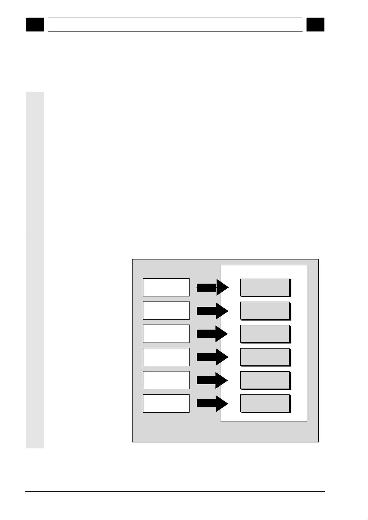
Operating areas
The basic functions are grouped in the following operating areas in the
control (in gray boxes):
Execution
of part program s,
manual control
Editing data
fo r p ro gra m s/
tool ma nagem ent
Development
and ad aptation
of part program s
Reading in/out
and archivin g
programs an d data
Alarm display s,
service displays
Adaptation of NC
data to m ac h ine ,
system settings
Operating areas
MACHINE
PARAMETERS
PROGRAM
SERVICES
DIAGNOSIS
START-UP
1-18 SINUMERIK 840Di sl/840D sl/840D Operating Manual HMI-Advanced (BAD) - 01/2008 Edition
© Siemens AG 2008 All rights reserved.
Page 19

01/2008 Introduction
1
The user can call up all the functions via the user interface.
The user interface consists of:
• Display units such as screen, LEDs, etc.
• Control elements such as keys, switches, handwheels, etc.
Read Chapter 2 "Operation" carefully before proceeding with further
chapters.
All subsequent chapters are written on the assumption that you have
done so!
1.2 Handling information
1.2 Handling information
Caution
1
The operator panel front/machine control panel may only be opened
by trained personnel for servicing purposes.
Before operating any of the control elements on this operator panel
Danger
Never open the operator panel front/machine control panel unless the
power supply has been disconnected! Failure to comply could result in
fatal injury!
Warning
Electronic components inside the operator panel/machine control
panel can be destroyed by electrostatic discharge if they are handled
incorrectly.
front:
Please first read the explanations supplied in this documentation!
© Siemens AG 2008 All rights reserved.
SINUMERIK 840Di sl/840D sl/840D Operating Manual HMI-Advanced (BAD) - 01/2008 Edition 1-19
Page 20
Introduction 01/2008
A
1.3 Switching on/switching off the control
1
1.3 Switching on/switching off the control
Switching on
Function
A variety of methods can be employed to switch on the power supply
to the control system or to the whole plant.
Machine manufacturer
1
Switching off
Please follow the machine manufacturer's instructions!
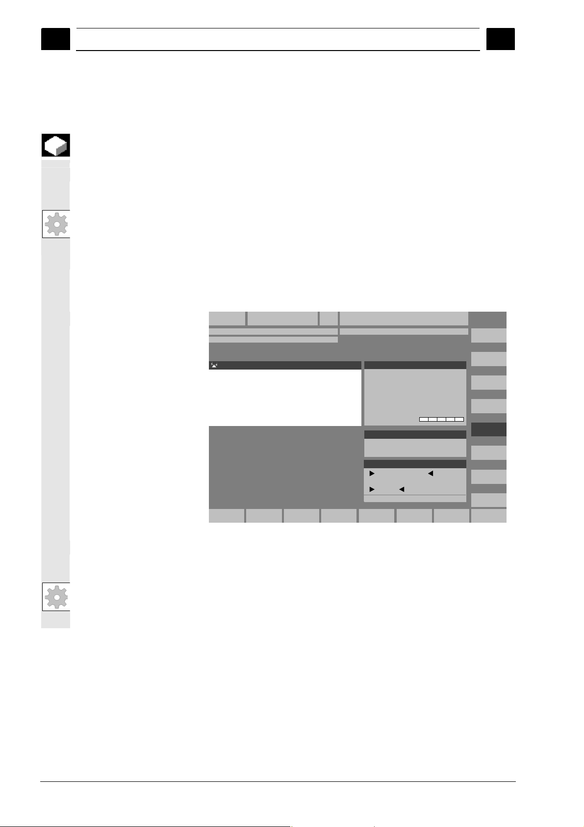
fter the control has been switched on, the "Reference point
approach" display or another main screen programmed by the
machine manufacturer will appear.
Machine
Channel Reset
Program aborted
MKS Position.Repos-Versch.
MCS Position
-X 0.000 mm
+X900.000mm0.000
+ X 900.000 mm 0.000
+Y 0.000 mm
- Y -156.000 mm 0.000
-Y-156.000mm0.000
+Z 0.000 mm
+ Z 230.000 mm 0.000
+Z230.000mm0.000
+0.000mm
Jog
Master spindle S1
Act. + 0.000 rev./min
Set 0.000 rev./min
Pos. 0.000 deg.
0.000 %
Power [%\
Feedrate mm/min
Act. 0.000 0.000 %
Set 0.000
Tool
preselected tool :
G0 G91
REF
Please follow the instructions below for switching off the control or the
entire system!
Machine manufacturer
Please follow the machine manufacturer's instructions!
1-20 SINUMERIK 840Di sl/840D sl/840D Operating Manual HMI-Advanced (BAD) - 01/2008 Edition
© Siemens AG 2008 All rights reserved.
Page 21
01/2008 Introduction
1
1.3 Switching on/switching off the control
1
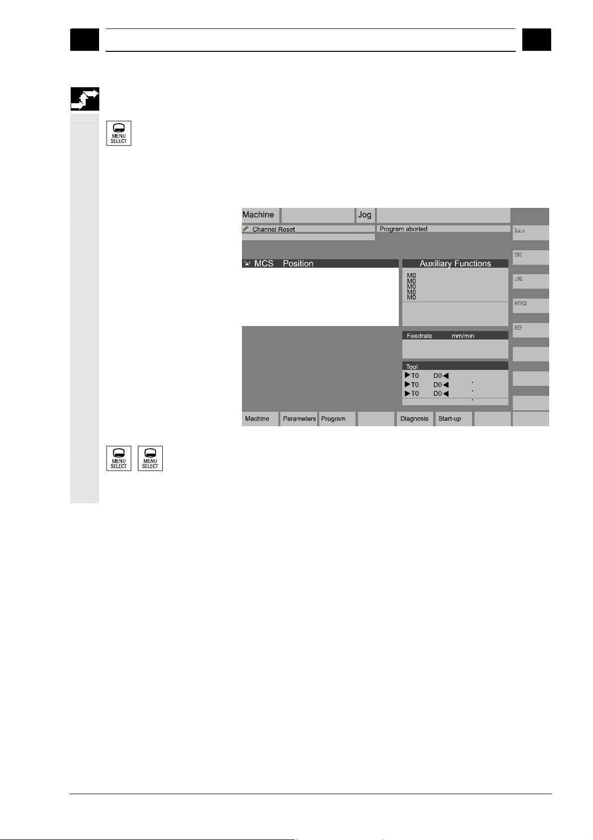
Sequence of operations
When you press the "Area switchover" key, operating areas are
displayed on the horizontal softkey bar and operating modes are
displayed on the vertical softkey bar. You can use this key to go to the
area menu bar from any location in the menu hierarchy if you wish to
select another operating mode or a different operating area.
+ X 900.000 mm
- Y -156.000 mm
+ Z 230.000 mm
H0.000000
H0.000000
H0.000000
Act. 3000.000 0.0 %
Set. 3000.000
G1
Services
By pressing the "Area switchover" key twice, you can toggle between
the operating areas last selected, e.g. between the "Parameters" and
"Machine" areas.
© Siemens AG 2008 All rights reserved.
SINUMERIK 840Di sl/840D sl/840D Operating Manual HMI-Advanced (BAD) - 01/2008 Edition 1-21
Page 22

Introduction 01/2008
1.3 Switching on/switching off the control
1
Notes
1
1-22 SINUMERIK 840Di sl/840D sl/840D Operating Manual HMI-Advanced (BAD) - 01/2008 Edition
© Siemens AG 2008 All rights reserved.
Page 23

01/2008 Operator Components/Operating Sequences
2
2.1 Operator panel front
Operator Components/Operating Sequences
2.1 Operator panel front.................................................................................................. 2-24
2.1.1 Keys on the operator panel front............................................................................... 2-24
2.1.2 Standard full keyboard.............................................................................................. 2-29
2.2 Machine control panel (MCP) ...................................................................................2-30
2.2.1 EMERGENCY STOP button ..................................................................................... 2-31
2.2.2 Operating modes and machine functions ................................................................. 2-31
2.2.3 Feedrate control........................................................................................................ 2-33
2.2.4 Spindle control ..........................................................................................................2-35
2.2.5 Key-operated switch ................................................................................................. 2-36
2.2.6 Program control......................................................................................................... 2-37
2.3 SINUMERIK HT 8 ..................................................................................................... 2-39
2.4 Screen layout ............................................................................................................ 2-42
2.4.1 Displaying the control states..................................................................................... 2-42
2.4.2 Global machine status display .................................................................................. 2-43
2.4.3 Program control display ............................................................................................ 2-48
2
2.5 General operating sequences...................................................................................2-50
2.5.1 Program overview and program selection ................................................................ 2-50
2.5.2 Changing the menu window...................................................................................... 2-51
2.5.3 Selecting a directory/file............................................................................................ 2-52
2.5.4 Editing inputs/values ................................................................................................. 2-53
2.5.5 Confirm/cancel input ................................................................................................. 2-54
2.5.6 Edit the part program in the ASCII editor.................................................................. 2-55
2.5.7 Switching over the channel....................................................................................... 2-61
2.5.8 Packet calculator....................................................................................................... 2-62
2.6 Calling the help function............................................................................................ 2-63
2.6.1 Editor help................................................................................................................. 2-65
2.6.2 Quick help for program commands........................................................................... 2-66
2.6.3 Extended help for program commands..................................................................... 2-69
2.7 Job list ....................................................................................................................... 2-70
2.7.1 Syntax description for job lists ..................................................................................2-72
2.7.2 Example of a job list with two-channel 1:1 links........................................................ 2-75
2.7.3 Example of a job list with multi-channel m:n links..................................................... 2-76
2.7.4 “Execute job list” operating sequence....................................................................... 2-77
2.7.5 Re-naming workpieces with job lists......................................................................... 2-79
2.7.6 Copying workpieces with job lists .............................................................................2-80
2.7.7 Archiving workpieces with job lists in the case of M:N.............................................. 2-80
© Siemens AG 2008 All rights reserved.
SINUMERIK 840Di sl/840D sl/840D Operating Manual HMI-Advanced (BAD) - 01/2008 Edition 2-23
Page 24
Operator Components/Operating Sequences 01/2008
2.1 Operator panel front
2
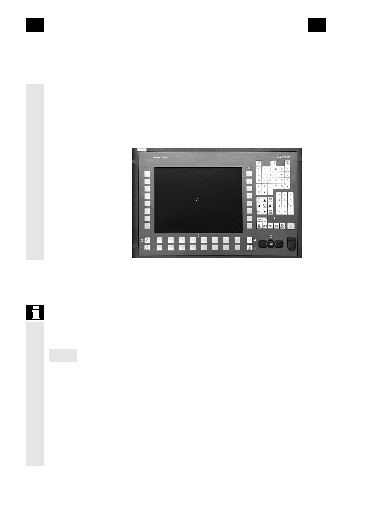
2.1 Operator panel front
A Display
Example
Properties
B Alphanumeric keypad
Correction/cursor keys
C Mouse and mouse keys
1 Machine area key
2 Recall (return)
3 Softkey bar (horizontal)
4 ETC key
(menu extension)
5 Area switchover key
6 Softkey bar (vertical)
In this example, the OP 012 SINUMERIK operator panel front is used
to illustrate the operator components, which are available for operating
the SINUMERIK control and machine tool.
The OP 012 operator panel front with 12.1" TFT color display with a
resolution of 800 x 600 pixels (SVGA) features a 59-key membrane
keypad as well as 2 x (8 + 2) horizontal and 2 x 8 vertical softkeys and
a built-in mouse.
2
2.1.1 Keys on the operator panel front
Keys on the operator
panel front
A function is called up by pressing one of the vertical softkeys. The
The elements of the operator panel keyboard and the symbols used to
represent them in this manual are shown and explained below.
The keys marked with an * correspond to the key symbols in US
layout.
Softkeys
Keys to which functions are assigned by means of a menu bar
displayed on the screen.
• It is possible to access further menu levels via the horizontal
softkeys in any operating area. Each horizontal menu item has a
vertical menu bar/softkey assignment.
• The vertical softkeys are assigned functions for the currently
selected horizontal softkey.
assignments of the vertical softkey bar can change if further subsidiary
functions are classified under a function.
2-24 SINUMERIK 840Di sl/840D sl/840D Operating Manual HMI-Advanced (BAD) - 01/2008 Edition
©Siemens AG 2008 All rights reserved.
Page 25
01/2008 Operator Components/Operating Sequences
2
2.1 Operator panel front
2
Parameter
Softkey (horizontal or vertical):
This key symbol indicates that you must have selected an operating
area or a menu item or have already performed certain functions
before you are able to execute the function described in the relevant
section.
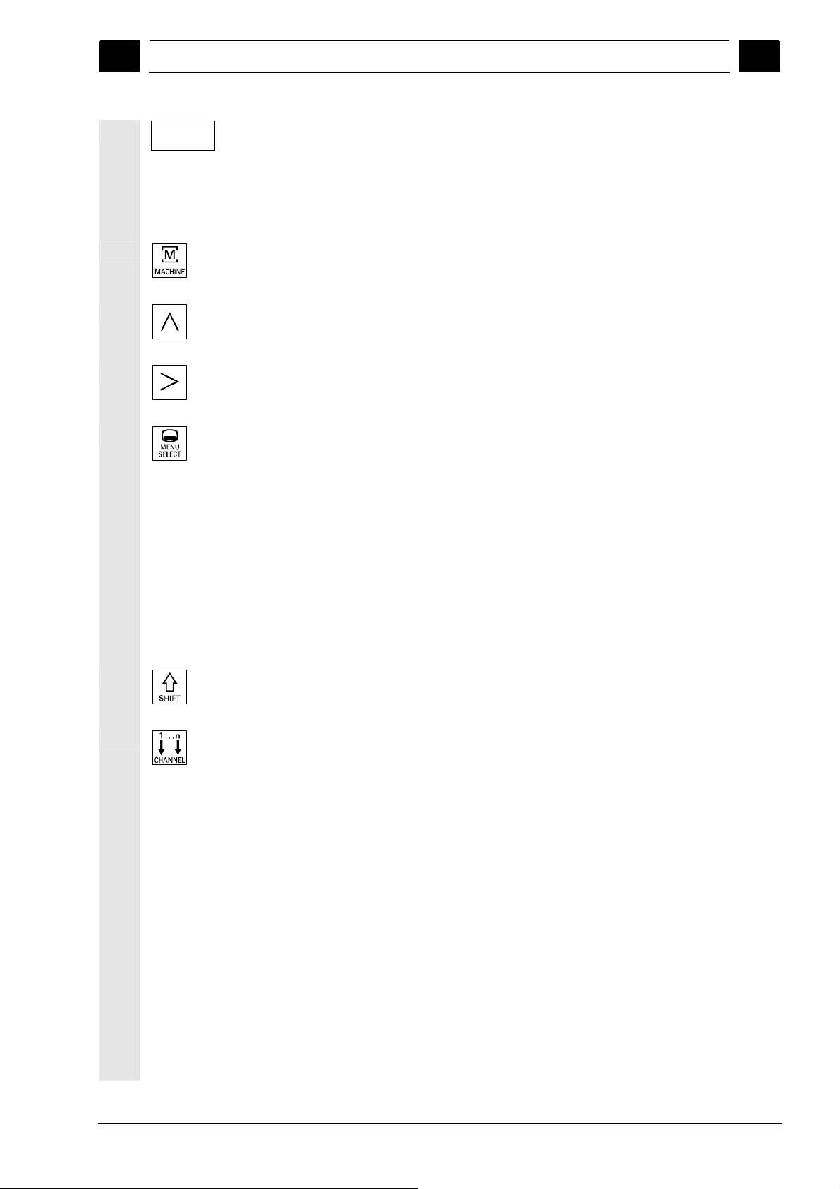
Machine area key
Direct branch to the "Machine" operating area.
Recall key
Return to the higher-level menu. Recall closes a window.
ETC key
Expansion of the horizontal softkey bar in the same menu.
Area switchover key
You can call the main menu from any operating area by pressing this
key. Pressing the key twice in succession changes from the current
operating area to the previous one and back again.
The standard main menu branches into the following operating areas:
1. Machine
2. Parameters
3. Program
4. Services
5. Diagnostics
6. Commissioning
Shift key
Switches between functions on keys with double assignment.
Switch over channel
In a configuration with several channels, it is possible to switch
between channels (switch from channel 1 through to channel n).
When a "Channel menu" is configured, all existing communication
links to other NCUs plus the associated channels are displayed on
softkeys.
(See Section "Switch over channel")
© Siemens AG 2008 All rights reserved.
SINUMERIK 840Di sl/840D sl/840D Operating Manual HMI-Advanced (BAD) - 01/2008 Edition 2-25
Page 26
Operator Components/Operating Sequences 01/2008
2.1 Operator panel front
2
2
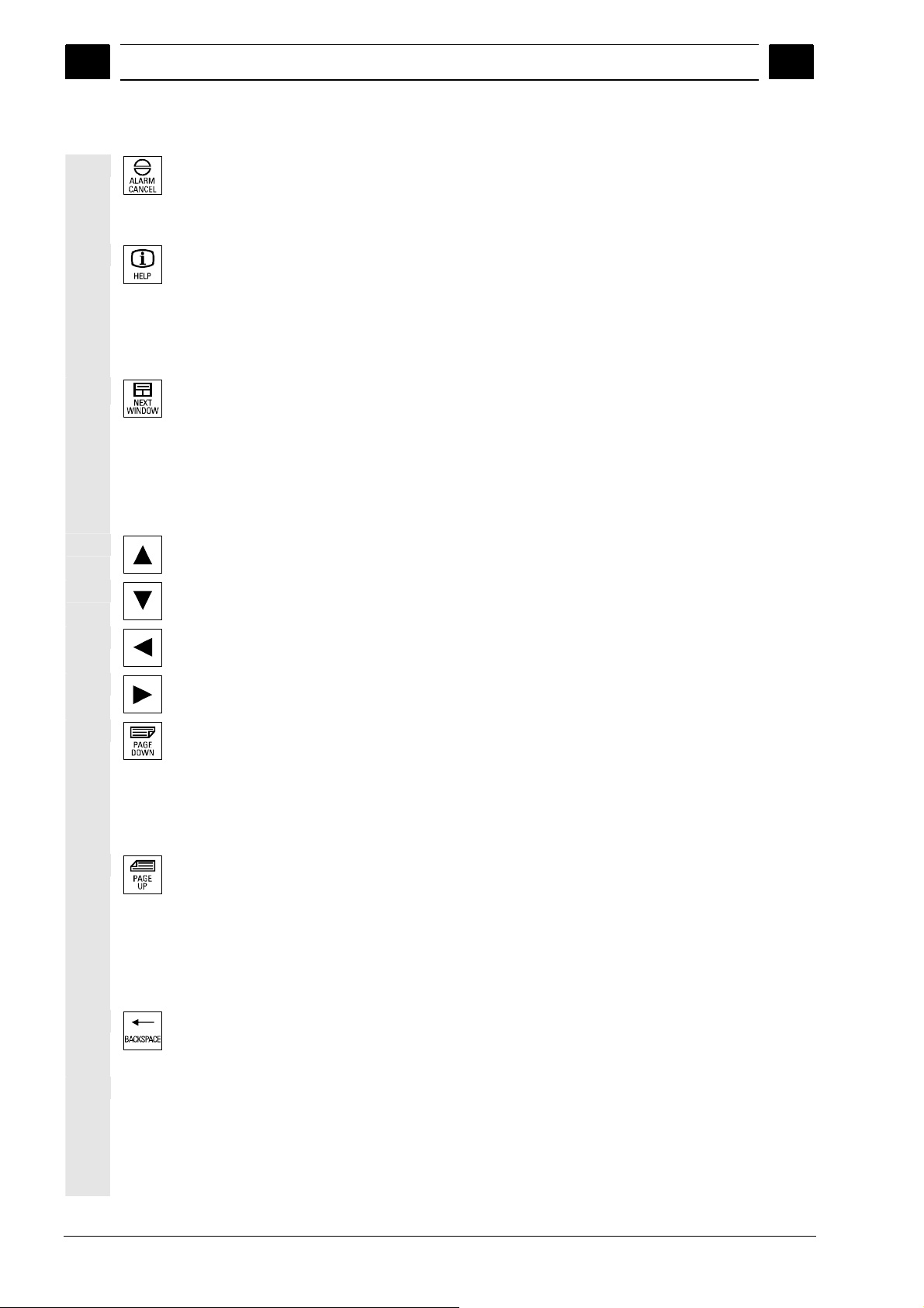
Acknowledge alarm key
By pressing this key, you can acknowledge the alarm marked by this
Cancel symbol.
Information key
This key displays explanatory information about the current operating
status (e.g. support for programming, diagnostics, PLC, alarms).
The letter "i" displayed in the user response line indicates that
information is available.
Window selection key
If several windows are displayed on the screen, it is possible to make
the next window the active one using the window selection key (the
active window has a thicker border).
Keyboard input e.g. the page keys, is possible only in the active
window.
Cursor up
Cursor down
Cursor to the left
Cursor to the right
PAGE DOWN
You "scroll" down by one display.
In a part program, you can "scroll" the display down (to end of
program) or up (to start of program).
PAGE UP
You "scroll" up by one display.
With the page keys you scroll the visible/displayed area of the window
that is active. The scroll bar indicates which part of the
program/document/... is selected.
Backspace
Delete characters from right
Space character (Blank)
2-26 SINUMERIK 840Di sl/840D sl/840D Operating Manual HMI-Advanced (BAD) - 01/2008 Edition
©Siemens AG 2008 All rights reserved.
Page 27
01/2008 Operator Components/Operating Sequences
2
2.1 Operator panel front
2
*
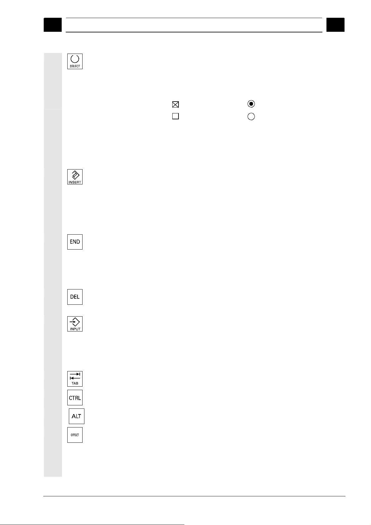
Selection key
• Selection key for values set in input fields and selection lists
labeled with this key symbol.
• Activate/deactivate a field:
Multiple option button
(you can select several options or
none)
Edit key / undo key
• Switch over to edit mode in tables and input fields (in this case, the
input field is in insert mode) or
• UNDO function on table elements and input fields (the value is not
validated when you exit a field using the edit key; instead it is reset
to the previous value = UNDO).
End of line key
• With this key, the cursor is moved to the end of the line in the
• Rapid positioning of the cursor on a group of related input fields.
• Has same effect as Tab key.
Delete key
The setting in a parameterization field is deleted.
The field remains blank.
Input key
• Accepts an edited value
• Opens/closes a directory
• Opening a file
Tab key
Ctrl key
Alt key
Tool offset Takes you directly to the tool offset
= active
= not active
page opened in the editor.
= active
= not active
Single-option button/option
(only one option can be active at a
time)
© Siemens AG 2008 All rights reserved.
SINUMERIK 840Di sl/840D sl/840D Operating Manual HMI-Advanced (BAD) - 01/2008 Edition 2-27
Page 28

Operator Components/Operating Sequences 01/2008
2.1 Operator panel front
2
“PROGRAM” hardkey
*
*
2
Program management program overview
A program can be opened in the text editor.
Interrupt Takes you directly to the Alarms
screen
User key Can be configured by the customer
Notes
The keys marked with an * also have a function in conjunction with
ShopMill/ShopTurn.
For this function to work, at least one recently edited program must be
found with sufficient read rights. The program must not be already
open in either a simulation or any other application. Actions such as
load, copy, select, etc. must not be in progress and the part program
must not be running on the NC.
In the above cases, the operation is denied with alarms 1203xx.
Press this hardkey in any operating area to reopen and display the
part program or file last edited in the Program operating area:
• If you are already in the Program operating area and the editor is
open, the program you last edited is displayed.
• If you are in any other operating area, and the editor is open, you
jump back to the editor in the Program operating area and the
most recent editor status is displayed.
If the editor is not open:
• If you are in another user application, you jump back to the
Program operating area and the editor is opened with the program
you last edited.
2-28 SINUMERIK 840Di sl/840D sl/840D Operating Manual HMI-Advanced (BAD) - 01/2008 Edition
©Siemens AG 2008 All rights reserved.
Page 29
01/2008 Operator Components/Operating Sequences
2
2.1.2 Standard full keyboard
Softkey assignment
2.1 Operator panel front
2
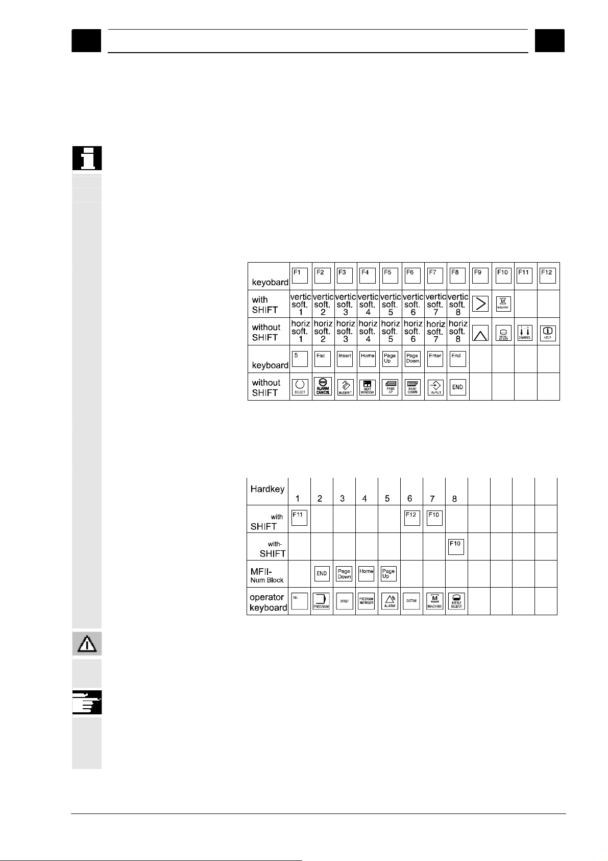
A full standard keyboard can be connected. However, a machine
control panel is required in addition to this keyboard.
The special function keys of the operator keyboard can also be used
with the full PC keyboard. The following table shows how the
horizontal and vertical softkeys and the special keys for the operator
panels are mapped onto the PC keyboard keys:
Full
Hardkey assignment
Caution
Full
The following table shows how the hardkeys of the MF 2 keyboard on
the PC are mapped onto the keys for the operator panels:
Hard-
Hard-
Hard-
Hard-
Hard-
MFII
MFII
out
key
Position
key
key
key
key
Hard key
Hard-
key
Hard key
The full standard keyboard does not meet the requirements (EMC) of
a SINUMERIK control. For this reason, it can be used only for
installation and service purposes.
Additional information
Since the English version of Windows is used in the control, the
keyboard language is English. A different keyboard language cannot
be set.
© Siemens AG 2008 All rights reserved.
SINUMERIK 840Di sl/840D sl/840D Operating Manual HMI-Advanced (BAD) - 01/2008 Edition 2-29
Page 30
Operator Components/Operating Sequences 01/2008
2.2 Machine control panel (MCP)
2
2.2 Machine control panel (MCP)
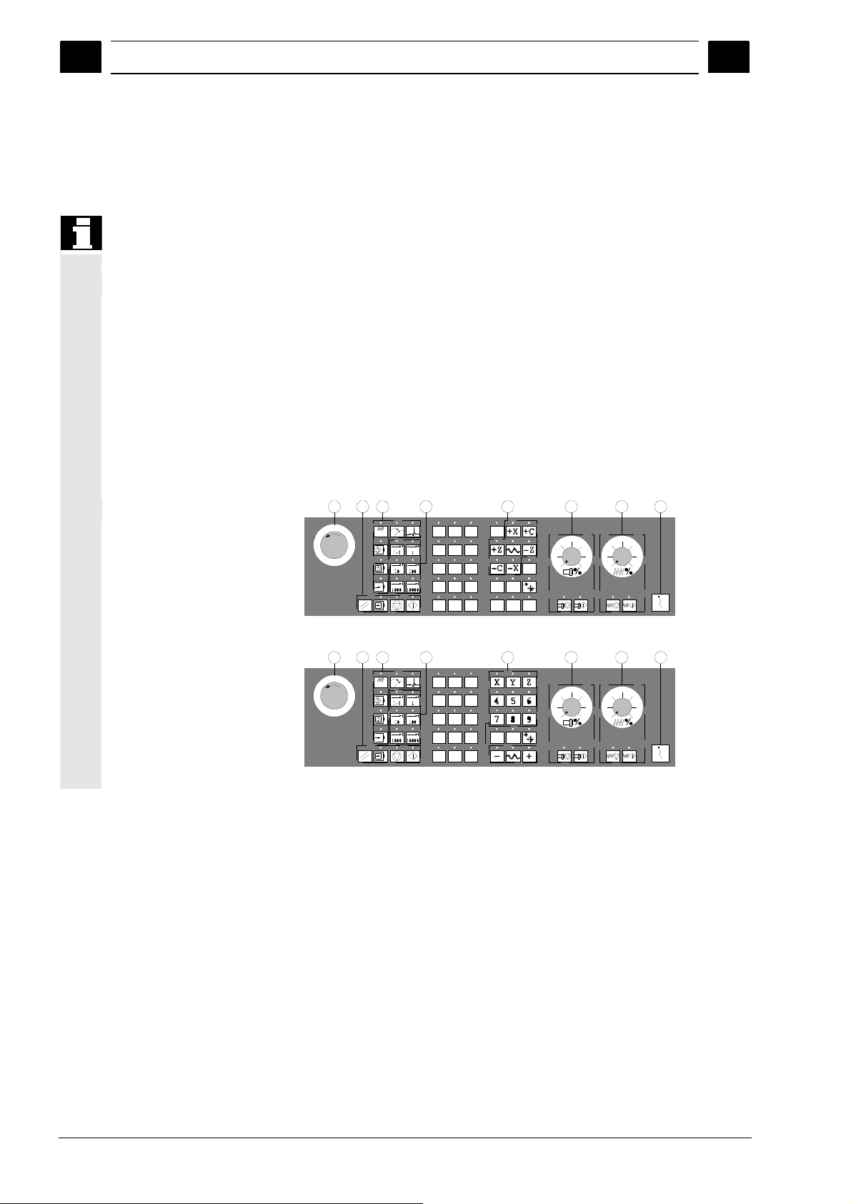
The machine tool can either be equipped with a standard machine
1 EMERGENCY STOP
button
2 Operating modes (with
machine functions)
3 Incremental mode
4 Program control
instructions
5 Direction key with rapid
traverse override
6 Spindle control
7 Feedrate control
8 Key-operated switch
Actions on the machine tool, for example traversing the axes or
program start, can only be initiated via a machine control panel.
control panel from SIEMENS (ordering data option) or with a specific
machine control panel from the machine-tool manufacturer.
The following description applies to the 19" machine control panel
supplied by SIEMENS (= standard). If you are using another machine
control panel, please consult the operating instructions of the
machine-tool manufacturer.
The standard machine control panel is equipped with the following
control elements:
4
1
Machine control panel for turning machines
1 4 2 3 5 6 7 8
Machine control panel for milling machines
2 3 5 6 7 8
2
2-30 SINUMERIK 840Di sl/840D sl/840D Operating Manual HMI-Advanced (BAD) - 01/2008 Edition
©Siemens AG 2008 All rights reserved.
Page 31

01/2008 Operator Components/Operating Sequences
2
2.2.1 EMERGENCY STOP button
EMERGENCY STOP button
2.2 Machine control panel (MCP)
2
Machine manufacturer
Press this red key in emergency situations:
1. if life is at risk
2. When there is a danger of the machine or workpiece being
damaged.
As a rule, when operating the EMERGENCY STOP button, all drives
are brought to a standstill with max. braking torque.
For details of other or additional responses to an EMERGENCY
STOP:
Please read the information supplied by the machine tool
manufacturer!
2.2.2 Operating modes and machine functions
Modes of operation
The keys marked with an * correspond to the key symbols in US
Jog
MDA
Auto
*
The active mode is signaled and confirmed by the associated LED,
which lights up.
layout.
If you press a "Mode key", the corresponding mode is selected if
permissible, and all other modes and functions are deselected.
JOG
(Jogging)
Axis travel in jog mode via:
• Continuous motion of the axes using the direction keys, or
• Incremental motion of the axes using the direction keys, or
• Handwheel
MDA
(Manual Data Automatic)
Control of machine through execution of a block or a sequence of
blocks. The blocks are entered on the operator panel front.
Automatic
Control of machine through automatic execution of programs.
© Siemens AG 2008 All rights reserved.
SINUMERIK 840Di sl/840D sl/840D Operating Manual HMI-Advanced (BAD) - 01/2008 Edition 2-31
Page 32

Operator Components/Operating Sequences 01/2008
2.2 Machine control panel (MCP)
2
2
A machine data code defines how the incremental dimension is
Inc keys
You can activate the Inc functions in conjunction with the following
VAR
1
1000 10000
Machine functions
10
100
modes:
• "JOG" mode
• "MDA/Teach-in" operating mode
Inc VAR (Incremental feed VARiable)
Incremental mode with variable increment size
(see operating area Parameters, Setting data).
Inc (Incremental feed)
Incremental mode with fixed increment size of 1, 10, 100, 1,000,
10,000 increments.
interpreted.
MDA
JOG
JOG
Teach In
Repos
Ref Point
Teach In
Creation of programs in interactive mode with the machine in
"MDA" mode.
Repos
Repositioning
Reposition, re-approach contour in "JOG" mode.
Ref
Approaching a reference point
Approach the reference point (Ref) in "JOG" mode.
2-32 SINUMERIK 840Di sl/840D sl/840D Operating Manual HMI-Advanced (BAD) - 01/2008 Edition
©Siemens AG 2008 All rights reserved.
Page 33

01/2008 Operator Components/Operating Sequences
2
2.2.3 Feedrate control
Feed Stop
Feed Start
2.2 Machine control panel (MCP)
2
Feedrate rapid traverse override (feedrate override switch)
Control range:
0% to 120% of programmed feedrate.
In rapid traverse, the 100% value is not exceeded.
Settings,
0%, 1%, 2%, 4%, 6%, 8%, 10%, 20%, 30%, 40%, 50%, 60%, 70%,
75%, 80%, 85%, 90%, 95%, 100%, 105%, 110%, 115%, 120%
Feed stop
If you press the "Feed stop" key:
• Execution of the current program is stopped
• The axis drives are brought to a standstill under control,
The associated LED lights up as soon as feed stop has been
accepted by the control and
The following appears in the header (program control display):
FST (= Feed Stop)
Example:
− In "MDA" mode, an error is detected during execution of a block.
− A tool change is to be carried out.
Feed start
If you press the "Feed start" key:
• The part program is continued in the current block,
• The feedrate is accelerated to the value specified by the program,
• The associated LED lights up as soon as feed start has been
accepted by the control.
© Siemens AG 2008 All rights reserved.
SINUMERIK 840Di sl/840D sl/840D Operating Manual HMI-Advanced (BAD) - 01/2008 Edition 2-33
Page 34

Operator Components/Operating Sequences 01/2008
2.2 Machine control panel (MCP)
2
2
+X +Z
X
X
+
Rapid
Machine manufacturer
WCS MC S
...
Z
9th Axis
Axis keys (for turning machines):
Press these keys to traverse the selected axis (X ... Z) in the positive
direction.
Press these keys to traverse the selected axis (X ... Z) in the negative
direction.
Axis keys (for milling machines):
Select the axis (X ... 9) for traversing
in the positive direction by pressing the "+" key or
in the negative direction by pressing the "-" key.
Rapid traverse override
If you press this key together with key "+" or "-", the axis moves in
rapid traverse mode.
• The specified increments and control range apply to standard
machines.
• Increments and control range can be modified by the machine tool
manufacturer to suit specific applications.
• Feedrate/rapid traverse feedrate and the values for the feedrate
override positions (if the feedrate override switch is also active for
rapid traverse) are defined in the machine data (see the
information supplied by the machine manufacturer).
MCS/WCS
You can switch between the machine and workpiece coordinate
systems in the Machine operating area using softkeys (MCS)/(WCS)
or the corresponding key on the machine control panel.
2-34 SINUMERIK 840Di sl/840D sl/840D Operating Manual HMI-Advanced (BAD) - 01/2008 Edition
©Siemens AG 2008 All rights reserved.
Page 35

01/2008 Operator Components/Operating Sequences
2
2.2.4 Spindle control
2.2 Machine control panel (MCP)
2
Spindle override (spindle speed override switch)
The rotary switch with latch positions allows you to increase or
decrease the programmed spindle speed "S" (equivalent to 100%).
The set spindle speed value "S" is output as an absolute value and a
percentage in the "Spindles" display (vertical softkey on main screen).
Control range:
50% to 120% of programmed spindle speed
Increment:
5% between latch positions
Spindle Stop
Spindle Start
Machine manufacturer
Spindle stop
*
When you press the "Spindle stop" key:
The spindle is decelerated down to zero speed and
The associated LED lights up as soon as "Spindle stop" is reached.
Example:
To change a tool
To enter S, T, H, M functions during setup
Spindle start
When you press the "Spindle start" key:
The spindle speed is accelerated to the value defined in the program
and
The associated LED lights up as soon as "Spindle start" has been
accepted by the control.
• The specified increment and the control range apply to standard
machine data (MD). These MD can be edited by the machine-tool
manufacturer to suit the specific application.
• The maximum spindle speed and the values for the spindle speed
override position are defined in the machine data and setting data
(see information supplied by the machine-tool manufacturer).
© Siemens AG 2008 All rights reserved.
SINUMERIK 840Di sl/840D sl/840D Operating Manual HMI-Advanced (BAD) - 01/2008 Edition 2-35
Page 36

Operator Components/Operating Sequences 01/2008
2.2 Machine control panel (MCP)
2
2.2.5 Key-operated switch
Machine manufacturer
SIEMENS key-operated
switch
Changing access rights
2
Functions can be assigned to key-operated switch positions by the
machine manufacturer. Using machine data, it is also possible to set
access to programs, data and functions to suit the user's
requirements.
The key-operated switch on the SINUMERIK 840D has 4 settings,
assigned to protection levels 4 to 7.
The key-operated switch has three different colored keys which can
be removed in the specified positions:
Switch positions
Position 0
No key
Protection level 7
Position 1
Key 1 black
Protection level 6
Position 2
Key 1 green
Protection level 5
Position 3
Key 1 red
Protection level 4
The screen is not automatically updated after a change in access
authorization (e.g., when the key-operated switch position is
changed), but only when the screen is next refreshed (e.g., on closing
and opening a directory).
The currently valid access authorization is checked every time a
function is executed.
If the PLC is in the STOP state, the input image of the machine control
panel is not scanned. For this reason, the key-operated switch
positions are not evaluated during commissioning.
Access authorization
Access authorization
Lowest
⏐
⏐
⏐
⏐
⏐
⏐
⏐
⏐
⏐
⏐
⏐
⏐
⏐
⏐
⏐
⏐
⏐
⏐
⏐
⏐
⏐
⏐
⏐
⏐
⏐
↓
Highest
2-36 SINUMERIK 840Di sl/840D sl/840D Operating Manual HMI-Advanced (BAD) - 01/2008 Edition
©Siemens AG 2008 All rights reserved.
Page 37

01/2008 Operator Components/Operating Sequences
2
Passwords As an additional option for setting access authorization, it is possible
to enter three passwords in the "Commissioning" operating area.
If the password is set, the key-operated switch positions are irrelevant.
References /IAD/, Commissioning Manual 840D.
2.2 Machine control panel (MCP)
2
2.2.6 Program control
Cycle Start
Cycle Stop
Single Block
NC Start
If you press the "NC Start" key, the selected part program (part
program name is displayed in header) is started at the current block
and the associated LED lights up.
NC stop
If you press the "NC Stop" key, processing of the active part program
is halted and the associated LED lights up.
After this, you can continue processing with NC Start.
Single block
This function allows you to execute a part program block by block.
You can activate the "Single Block" function in "Automatic" and "MDA"
modes. If single block is activated, the associated LED on the
machine control panel lights up.
• If single block execution is active, Stop is displayed on the screen
in the cycle (in the program control line)
• The message "Stop: Block completed in single block" is displayed
in the channel operational message line (in interrupt state).
• The current block in the part program will not be executed until you
press the "NC Start" key.
• Program processing is stopped after one block is executed.
You can execute the next block by pressing the "NC Start" key again.
You can deselect the function by pressing the "Single block" key
again.
© Siemens AG 2008 All rights reserved.
SINUMERIK 840Di sl/840D sl/840D Operating Manual HMI-Advanced (BAD) - 01/2008 Edition 2-37
Page 38

Operator Components/Operating Sequences 01/2008
2.2 Machine control panel (MCP)
2
This function is dependent on the settings under "Program control" in
the Machine operating area.
Reset
References /FB/ K1, Description of Functions BAG, Channel, Program control.
Reset
When you press the <Reset> key:
• Execution of the current part program is aborted.
• Messages issued by the monitoring function are deleted (except
the alarms POWER ON, NC Start and "Acknowledge alarm").
• The channel is set to "Reset" state, i.e.,
− The NC control remains synchronized with the machine.
− The control is in its initial state and ready for a new program
run.
2
2-38 SINUMERIK 840Di sl/840D sl/840D Operating Manual HMI-Advanced (BAD) - 01/2008 Edition
©Siemens AG 2008 All rights reserved.
Page 39

01/2008 Operator Components/Operating Sequences
2
2.3 SINUMERIK HT 8
Prerequisite
2.3 SINUMERIK HT 8
The mobile SINUMERIK HT 8 handheld terminal combines the
functions of an operating panel and a machine control panel. It is
therefore ideal for visualization, operation, teach-in, and programming
at the machine:
- Manipulators/robots
- Machine tools
- Production machines
The 7.5 TFT color display provides touch operation. It also has
membrane key for traversing the axes, for numeric input, for cursor
control, and for machine control panel functions like start and stop.
To operate the HT 8, you must have the operator privilege.
2
© Siemens AG 2008 All rights reserved.
SINUMERIK 840Di sl/840D sl/840D Operating Manual HMI-Advanced (BAD) - 01/2008 Edition 2-39
Keyboard operation
Machine manufacturer
See section “Machine control panel” for a description of the individual
keys.
The four customer keys are freely assignable and can be set up
customer-specifically by the machine manufacturer.
This <STANDBY> key presently has no function.
Page 40

Operator Components/Operating Sequences 01/2008
2.3 SINUMERIK HT 8
2
2
Key <U>
CPF softkeys
(Control Panel Function)
The CPF softkey bar is displayed with the <U> key:
The CPF softkeys keys of the machine control panel emulated by the
HMI software. When the HT 8 has operator rights, the CPF menu is
displays with the <U> key. The menu is automatically hidden when the
area is changed.
The following softkeys are available (see figure on the left):
• <MACHINE> softkey: Select the "Machine" operating area
(corresponds to <Shift> + <F10>).
• < [VAR] > softkey: Select the axis feedrate in the increment.
• <Single Block> softkey: Switch single block execution on/off.
• <WCS MCS> softkey: Switching between MCS ↔ WCS
• "Back" softkey: Hide CPF menu; restoration of the user response
line and the softkeys.
The CPF menu is not displayed when the area menu or the channel
menu is active.
With the <MACHINE> softkey, the "multi-channel display" function is
also operator-controllable on the HT 8. The respective state is
displayed in the global machine status display (header).
(Mail Detlev Lutter from 15.06.2007)
Traversing keys
Switch over channel
Back
The PLC interface signals, that are initiated using the softkeys of the
CPF menus, are edge-controlled.
JOG and MDA / Teach In mode must be selected to set up the axes
with the traversing keys.
The labeling of the 12 traversing keys is shown on the housing of the
touch panel. Display of the labeling for up to 6 axes is performed by
the PLC program (machine manufacturer).
If the labeling for the traversing keys is displayed, all the other
softkeys cannot be operated.
Channel switchover is performed by touch operation of the touch
surface on the global machine status display:
2-40 SINUMERIK 840Di sl/840D sl/840D Operating Manual HMI-Advanced (BAD) - 01/2008 Edition
©Siemens AG 2008 All rights reserved.
Page 41

01/2008 Operator Components/Operating Sequences
2
2.3 SINUMERIK HT 8
2
Virtual keyboard
Language changeover
Calibrating touch panel
References
The virtual keyboard is displayed from the active operator area. The
keyboard is automatically hidden again when changing the area or
when exiting the application. The virtual keyboard is located across
the complete header and can be shifted using the mouse.
The following languages can be selected for the virtual keyboard
online: German, English, French, Spanish.
The virtual keyboard can be displayed and hidden in all operator
areas using a touch field located above the vertical softkeys. This
touch field is only displayed if the connected HT 8 or Touch Panel has
operator rights.
To perform calibration, press the keys <Recall> + <MENU SELECT>
simultaneously to start the command shell:
1. The "Calibrate TouchPanel" button starts calibration.
2. Follow the instructions on the screen and touch the three
calibration points one after the other.
This completes the calibration.
3. Then press the horizontal softkey or button "1" to make the
connection to the required PCU and return to the HMI-Advanced
user interface.
“Operator Components and Networking” Manual
© Siemens AG 2008 All rights reserved.
SINUMERIK 840Di sl/840D sl/840D Operating Manual HMI-Advanced (BAD) - 01/2008 Edition 2-41
Page 42

Operator Components/Operating Sequences 01/2008
2.4 Screen layout
2
2.4 Screen layout
2.4.1 Displaying the control states
Global machine status display
CHAN1 \MPF.DIR
1 4 6
Machine
Channel interrupted
Stop: No NC Ready
2
MCS Position Repos offset Auxiliary Functions
+ X 900.000 mm 0.000
- Y -156.000 mm 0.000
+ Z 230.000 mm 0.000
11
13
11
16
>
Machine
12
Parameters
Program Services Diagnosis
Jog
3
5
SHAFT1.MPFP
Program stopped
DRY ROV
M0
M0
M0
M0
M0
H0.000000
H0.000000
H0.000000
Feedrate mm/min
Act. 3000.000 0.0 %
Set. 3000.000
Tool
preselected tool:
G0 G91
7
11
Start-up
2
8
9
11
.
11
10
i
Auto
MDI
JOG
REPOS
REF
17
Vertical
softkeys
19
>
Horizontal softkeys
18
1 Operating areas
2 Channel status
3 Channel operational messages
4 Channel name
5 Alarm and message line
6 Operating mode, submode, (increment if relevant)
7 Program name of the selected program
8 Program status
9 Program control
10 Additional information (help)
i You can display information by pressing the i key
^ Recall: Return to higher-level menu
> ETC.: Expansion of the horizontal softkey bar in the same.
Menu
2-42 SINUMERIK 840Di sl/840D sl/840D Operating Manual HMI-Advanced (BAD) - 01/2008 Edition
©Siemens AG 2008 All rights reserved.
Page 43

01/2008 Operator Components/Operating Sequences
2
2.4 Screen layout
2
11 Working windows, NC displays
The working windows (program editor) and NC displays (feedrate,
tool) available in the selected operating area are displayed here.
The unit for positional data is preceded by the diameter symbol ∅
in the work pane if the axis is currently the transverse axis and if
the tool coordinate system is set. If diameter programming is
disabled with DIAMOF, the symbol preceding the unit is no longer
visible.
12 User response line with user information
Here user information is displayed for the selected function (if
available).
13 Focus
The selected pane is highlighted by a frame. The window header
display is inverted. Data entered on the operator panel front apply
to this window.
16 Recall function, i.e., key ^ is active
17 ETC. function, i.e., > key is active
18 Horizontal softkeys
19 Vertical softkeys
The softkey functions available in the selected operating area are
displayed in the horizontal/vertical softkey bar (corresponding to F1
to F8 on the full keyboard).
Additional information
The screen layout may differ slightly from the layout displayed above,
depending on the screen size or resolution used.
2.4.2 Global machine status display
1 Operating areas The currently selected operating area is displayed (Machine,
Parameters, Program, Services, Diagnostics, Commissioning).
2 Channel status The current channel status is displayed
- Channel reset
- Channel interrupted
- Channel active
3 Channel operational
messages
For displaying the channel operational messages with symbols:
© Siemens AG 2008 All rights reserved.
SINUMERIK 840Di sl/840D sl/840D Operating Manual HMI-Advanced (BAD) - 01/2008 Edition 2-43
Page 44

Operator Components/Operating Sequences 01/2008
2.4 Screen layout
2
2
If the status shows this symbol
2 Stop: Mode Group Ready
3 Stop: EMERGENCY STOP active
4 Stop: Alarm active with stop
5 Stop: M0/M1 active
6 Stop: Block ended in SBL mode
8 Wait: No read-in enable
9 Wait: No feed enable
12 Wait: No axis enable
17 Wait: Feedrate override > 0%
18 Stop: Error in NC block
19 Wait: For external NC blocks
, operating input is required.
1 Stop: No NC Ready
7 Stop: Cycle stop active
22 Wait: No spindle enable
23 Wait: Axis feedrate value is 0
31 Stop: No channel ready
45 Stop: SERUPRO search has found search target and the
NCK has stopped. SERUPRO is the abbreviation for
“SEarchRUn by PROgram test”; it is a new type of
block search.
If the status shows this symbol
11 Wait: No aux. funct. ackn.
13 Wait: Exact stop not reached
14 Wait: For positioning axis
15 Wait: For spindle
operation is generally not required.
10 Wait: Remaining dwell time __ Sec. for seconds or
Remaining dwell time __ rev. for revolutions
This can be parameterized via an OPI variable. 0 =
sec./1 = rev.
16 Wait: For other channel
20 Wait: Due to SYNACT instruction
21 Wait: Block search active
2-44 SINUMERIK 840Di sl/840D sl/840D Operating Manual HMI-Advanced (BAD) - 01/2008 Edition
©Siemens AG 2008 All rights reserved.
Page 45

01/2008 Operator Components/Operating Sequences
2
24 Wait: For tool change acknowledgement
25 Wait: For gear stage change
26 Wait: For position control
27 Wait: For thread cut
2.4 Screen layout
2
30 Wait: For safe operation
32 Stop: Oscillation active
33 Stop: Axis replacement active (block change inhibited
34 Wait: For axis container rotation
35 Wait: AXCT axis active as slave axis
36 Wait: AXCT axis active as master axis
37 Wait: AXCT axis changing to follow-up
38 Wait: AXCT internal status change in axis
39 Wait: AXCT axis drive disable
29 Wait: For punching
because axis replacement in progress)
This delay status may be attributable to the following
causes:
• Activation of position control
• Requesting of zero marker
• Reference point approach active
• Parameter block change active
• Measuring system change active
• Measurement on-the-fly active
• Closed-loop controller enable removed
• Status change, axis/spindle disable
40 Wait: AXCT axis overlaid motion active
41 Wait: AXCT axis axis replacement active
42 Wait: AXCT axis interpolator active
43 Wait: WAIT_FOR_CC_ENABLE:
Waiting for compile cycle
44 Wait: On access to system variable
46 Stop: ESR triggered
47 Wait: Axis container rotation waiting for spindle stop
48 Wait: Axis container rotation waiting for synchronization of
MD data (New-Config)
© Siemens AG 2008 All rights reserved.
SINUMERIK 840Di sl/840D sl/840D Operating Manual HMI-Advanced (BAD) - 01/2008 Edition 2-45
Page 46

Operator Components/Operating Sequences 01/2008
2.4 Screen layout
2
49 Wait: For axis replacement: Axis currently coupled
50 Wait: For axis replacement: Lift fast active
51 Wait: For axis replacement: New-Config active
52 Wait: For axis replacement: Axis container rotation active
53 Wait: For axis replacement: Waitp active
54 Wait: For axis replacement: Axis is currently in another
channel
55 Wait: For axis replacement: Axis is currently a PLC axis
56 Wait: For axis replacement: Axis is currently an oscillating
axis
57 Wait: For axis replacement: Axis is currently a JOG axis
58 Wait: For axis replacement: Axis is currently a command
axis
2
59 Wait: For axis replacement: Axis is currently an OEM axis
61 Wait: For axis replacement: Axis is currently a coupled-
62 Wait: For axis replacement: Axis is currently a coupled
4 Channel name Name of the channel in which the program is running.
5 Alarm and message line - Alarms and messages or
6 Operating mode display The currently selected operating mode, i.e. JOG, MDA or AUTO
7 Program name Press NC Start to execute this program.
60 Wait: For axis replacement: Axis is currently a slave axis
- Instructions that were programmed in the part program using the
MSG command (if no alarms are active)
(automatic) is displayed.
The active submode is displayed next to the operating mode. An
active increment is also displayed underneath, e.g.,
JOG Repos
1000
The "Program name" output field can be configured for JOG and MDA
(see machine manufacturer's specifications).
coupled to the master value
motion slave axis
slave axis
2-46 SINUMERIK 840Di sl/840D sl/840D Operating Manual HMI-Advanced (BAD) - 01/2008 Edition
©Siemens AG 2008 All rights reserved.
Page 47

01/2008 Operator Components/Operating Sequences
2
8 Program status The current status of the part program being executed is output:
• Program aborted
• Program running
• Program stopped
The "program status" output field can be configured, e.g. with the
"Channel-wide status display with symbols" function (Subsection 4.1.3
and see machine manufacturer's specifications).
9 Program control display Functions that have been activated can be set via "Program control"
so that they are displayed.
(See Section 4.6 Automatic mode, “Program control”)
2.4 Screen layout
2
© Siemens AG 2008 All rights reserved.
SINUMERIK 840Di sl/840D sl/840D Operating Manual HMI-Advanced (BAD) - 01/2008 Edition 2-47
Page 48

Operator Components/Operating Sequences 01/2008
2.4 Screen layout
2
2.4.3 Program control display
SKP
Skip block
SKPn
SBL1
Single block with STOP after
each machine function block
SBL2
Single block with stop after
each block
SBL3
Stop in cycle
2
Function
Functions that have been activated are visible in the program control
display (can be set via "Program control", see Subsection 4.6.12). The
functions are displayed irrespective of the selected menu.
Program blocks in which the block number is preceded by a slash are
skipped when you run the program (e.g. "/N100 ..."). Up to 10 program
levels can be hidden (e.g., "/6N100 .."; the 7th program level is
hidden)
References: /PG/ Programming Manual Fundamentals, Chapter 2.
n = active skip levels
If this function is active, execution is interrupted after every block that
triggers a function on the machine
(calculation blocks do not cause an interruption).
If this function is active, the part program blocks are executed as
follows: Each block is decoded separately and execution is interrupted
after every block.
If this function is active, the part program blocks are executed
individually in the cycle as follows:
Each block is decoded separately and execution is interrupted after
every block. Part program blocks are
- Traversing blocks
- Switching and auxiliary functions
- Blocks generated internally in the controller (e.g. blocks inserted
for tool radius compensation)
- Thread blocks after retraction
- Thread blocks with dry run feedrate
Thread blocks without dry run feedrate are an exception to this. In
such blocks, a stop is only performed at the end of the current thread
block. SBL2 can only be selected in the Reset state.
Either SBL1 or SBL2 can be selected!
This function can be activated only in the "Single block" state.
2-48 SINUMERIK 840Di sl/840D sl/840D Operating Manual HMI-Advanced (BAD) - 01/2008 Edition
©Siemens AG 2008 All rights reserved.
Page 49

01/2008 Operator Components/Operating Sequences
2
2.4 Screen layout
2
DRY
DRY run feedrate
ROV
Rapid traverse override
M01
Programmed stop 1
Additional M fct.
Programmed stop 2
References
DRF
DRF selection
PRT
Program test
FST
Feed stop
Traverse movements are performed with the feedrate value set in the
setting data "Dry run feedrate".
This dry run feedrate function replaces the programmed motion
commands.
The override switch for the feedrate also applies to the rapid traverse
feedrate.
When this function is active, processing of the program is stopped at
every block in which miscellaneous function M01 is programmed. The
message "Stop: M00/M01 active" is then displayed on the screen.
Press the NC Start key to resume execution. If the function is not
activated, special function M01 (from the part program) is not taken
into account.
When this function is active, program execution on the NC is
interrupted on request by the PLC at blocks containing the additional
function for a conditional stop.
The machine data 22256: AUXFO_ASSOC_M1_VALUE you can
define a function associated with M01. The value of this miscellaneous
M function number is then equivalent to a programmed stop 2.
/FB1/Description of Functions - Basic Machine
Predefined Auxiliary Function "Associated auxiliary functions for M0,
M1"
When the "DRF" function is active, DRF offsets are applied.
If "Program test" is selected, the output of setpoints to axes and
spindles is disabled. The setpoint display "simulates" the traverse
movements.
The activated feed stop is displayed.
“Feed stop” is indicated in the feedrate window by means of the
symbol “Feedrate not enabled” and is omitted from the program
control display. This function is not activated/deactivated under
Program Control, but via the “Feed Start/Feed Stop” keys on the
machine control panel.
© Siemens AG 2008 All rights reserved.
SINUMERIK 840Di sl/840D sl/840D Operating Manual HMI-Advanced (BAD) - 01/2008 Edition 2-49
Page 50

Operator Components/Operating Sequences 01/2008
2.5 General operating sequences
2
2.5 General operating sequences
2
Keys
This identical functionality applies only if the operating areas are left
References Commissioning Manual HMI Advanced,
Functions
A range of keys are available in the various operating areas and
menus. The function of the keys is the same in all operating areas.
intact as supplied by Siemens AG and no modifications have been
configured by the user.
Additional information
It is possible to customize the menu trees. In this way, users are able
to define softkeys according to their individual needs. Due to this
capability, the menus and softkeys on your control may be different to
those described in this Operator's Guide.
see Chapter “Generating user operator menus”
The following section describes functions which you can select in
several operating modes.
2.5.1 Program overview and program selection
An overview of all workpiece directories/programs that exist is
Position the cursor on the desired workpiece/program.
Function
After selection of a workpiece or program overview, individual
workpieces or programs can be enabled or disabled for execution.
Sequence of operations
"AUTO" mode is selected in the "Machine" operating area.
The appropriate channel is selected.
The channel is in reset state.
The workpiece/program to be selected is in the memory.
displayed.
Select the workpiece/program for execution:
2-50 SINUMERIK 840Di sl/840D sl/840D Operating Manual HMI-Advanced (BAD) - 01/2008 Edition
©Siemens AG 2008 All rights reserved.
Page 51

01/2008 Operator Components/Operating Sequences
2
2.5 General operating sequences
2
Program
selection
The name of the selected workpiece is displayed on the screen in the
"Program name" field at the top. The program is then loaded.
2.5.2 Changing the menu window
Scroll in menu window:
Position cursor in menu window:
If a screen comprises several windows, you can use the "Window
selection" key to switch between the individual windows. You only
need to do this if you wish to enter data on the operator panel front.
The focus changes to the selected menu window (the header and
border of the active window appear in a different display format).
If the content of a window covers several screen pages, you can use
the "Page" keys to scroll up or down through the information.
A scroll bar indicates that the content of the window extends beyond
the visible display.
You can position the cursor at the desired point in the menu window
with the "Direction keys".
©Siemens AG 2008 All rights reserved.
SINUMERIK 840Di sl/840D sl/840D Operating Manual HMI-Advanced (BAD) - 01/2008 Edition 2-51
Page 52

Operator Components/Operating Sequences 01/2008
2.5 General operating sequences
2
2.5.3 Selecting a directory/file
Open/close directory:
Open file:
Select file
Select multiple files
2
The "Direction keys" can be used to position the cursor on the desired
directory/file.
If you enter a character on the alphanumeric keyboard, the cursor
moves to the first name that begins with the character.
Press the "Input" key to open or close a directory.
You can open a file with the "Input" key if you wish to edit it in the
ASCII editor. The editor is opened automatically.
This key is used to select a file. It is possible to select multiple files.
The symbol appears next to the cursor bar when a file is selected.
In order to select a block of files, press the "Shift" and "Cursor down"
keys simultaneously.
The first time you press the keys, the start of the block is selected.
The subsequent files are selected continuously
until you press the "Cursor up" or "Cursor down" (without "Shift") key.
or
Deselects a selected file.
Cancels all selections.
2-52 SINUMERIK 840Di sl/840D sl/840D Operating Manual HMI-Advanced (BAD) - 01/2008 Edition
©Siemens AG 2008 All rights reserved.
Page 53

01/2008 Operator Components/Operating Sequences
2
2.5 General operating sequences
2
2.5.4 Editing inputs/values
Multiple selector button
Position the cursor on the input field and start to type. When you begin
If you wish to edit inputs/values, the corresponding key is always
displayed automatically on the right of the input field. The following
input fields are available:
1. Option buttons (single selection button/multiple option
button):
You can use the "Select" key to activate or deactivate a selection field.
Single-option button/option button
(you can select several options or
none)
2. Input fields:
typing, you automatically switch to Insert mode.
Confirm your input with the "Input" key. The value is accepted.
To change an existing value, press the "Edit" key to switch to insert
mode.
Enter the value or word (e.g. file name, etc.) on the alphanumeric
keypad.
In some fields, it is possible to choose between several preset values
by means of the "Toggle" key.
3. Selection list
Selection lists show you a selected value from a list of possible
values.
Press the "Edit" key to open a complete list of possible or existing
values.
Position the cursor on the value of your choice using the "Direction"
keys.
= active
= not active
(only one option can be active at a
time)
= active
= not active
©Siemens AG 2008 All rights reserved.
SINUMERIK 840Di sl/840D sl/840D Operating Manual HMI-Advanced (BAD) - 01/2008 Edition 2-53
Page 54

Operator Components/Operating Sequences 01/2008
2.5 General operating sequences
2
2.5.5 Confirm/cancel input
2
Always confirm your input with the "Input" key. The value is accepted.
With this key, you can switch to the next value in the selection list
without displaying the entire list (e.g. to select from only a small
number of values/settings).
• The editor displays only the characters which can be input via the
operator panel front keyboard.
• A part program opened by the editor cannot be simultaneously
started in the NC (enable is canceled); an alarm (14014) is
indicated in this case. If the control is switched off while the editor
is open, the enable might have to be set manually.
Confirm input:
OK
Abort
Your inputs are accepted when you press the "OK" softkey. The
selected function is executed. The window is closed, and you return to
the menu level from which the window was called.
Cancel input:
Your inputs are rejected if you select the "Abort" softkey. The selected
function is aborted. The window is closed and you return to the menu
level from which the window was called.
This is the same as when returning from a function (vertical softkey
bar).
The "Edit" key can also have an "Undo" function if you abandon the
input/modification you have just entered. The cursor remains
positioned in the currently selected field.
Switch from the horizontal menu level back to the call menu level.
2-54 SINUMERIK 840Di sl/840D sl/840D Operating Manual HMI-Advanced (BAD) - 01/2008 Edition
©Siemens AG 2008 All rights reserved.
Page 55

01/2008 Operator Components/Operating Sequences
2
2.5 General operating sequences
2.5.6 Edit the part program in the ASCII editor
The ASCII editor provides you with the following functions:
Function
− Switch between insert and overwrite mode
− Select, copy, delete block
− Paste block
− Position cursor / find/replace text
− Saving a file
− Create contour (programming support)
− Parameterize cycles (drilling, milling, turning)
− Start simulation
− Recompile (cycles, free contour programming)
− Renumbering blocks
− Change settings
− 2. Open file
Additional information
2
A part program selected in the NC can generally only be edited when
the channel is in the reset state. When a part program is selected and
the relevant channel is in the "Channel Reset" state, the program can
be fully edited.
The end of block character is not displayed as "
displayed as "¶".
Please note:
It is possible to edit a program both directly in the NC and on the hard
disk in the ASCII editor. How programs are saved on the hard disk is
determined by settings.
The following functions are fully enabled in the Program and Services
Sequence of operations
operating areas but only partially in the Machine operating area.
In the Machine operating area, the ASCII editor is called via the
program editor, in Services, by selecting a file in the file manager.
You have selected the file you wish to edit in the directory
and pressed the "Enter" key,
the vertical softkey bar changes. Your selected file is opened in the
text editor.
L
"; instead it is
F
©Siemens AG 2008 All rights reserved.
SINUMERIK 840Di sl/840D sl/840D Operating Manual HMI-Advanced (BAD) - 01/2008 Edition 2-55
Page 56

Operator Components/Operating Sequences 01/2008
2.5 General operating sequences
2
2
Cursor block:
Use the "Direction keys" to position the cursor in the text.
You can page up and down using the "Page" keys.
The character on which the cursor is positioned is deleted.
Press the "Backspace" key to delete the character to the left of the
cursor.
Press the "Input" key to end a block. "L
automatically generated.
" ("Line Feed") is
F
Overwrite
Mark
block
Vertical softkeys
Overwrite
The cursor toggles between insert and overwrite modes.
Select block
When you press this softkey, the vertical softkey bar changes. The
softkey marks the beginning of a block.
Now position the cursor at the end of the block.
The block is selected automatically.
Copy
block
This softkey copies the selected block into the buffer.
If a line, which was generated by a support function, is selected the
complete support block is copied.
It remains stored in the buffer even if another part program
is selected.
Delete
block
The selected block is deleted.
If a line that was generated by a support function is selected the
complete support block is deleted.
Mark
block
Selection mode is canceled when you press "Select block".
Paste
block
Paste block
This softkey pastes the cut or copied block from the buffer into the text
in front of the cursor position.
2-56 SINUMERIK 840Di sl/840D sl/840D Operating Manual HMI-Advanced (BAD) - 01/2008 Edition
©Siemens AG 2008 All rights reserved.
Page 57

01/2008 Operator Components/Operating Sequences
2
2.5 General operating sequences
2
Find/
Go to...
Find/Go to...
The “Find/Go to…” dialog box opens. You can select functions for
positioning and searching via the vertical softkeys:
Program
start
Program
end
Go to...
Find
The following search methods are available:
• Search to the beginning of the part program (cursor on the first
character in the program)
• Search to the end of the part program (cursor on the last character
in the program) and
• Proceed to a particular NC block with "Go to.."
• Or search for a particular character string with "Find".
"Go to...": Enter the block number you are looking for.
• If the line being searched for contains an "N" or ":", you are taken
to the block in question.
• A message is output if there is no block with the specified number.
OK
Abort
Press the "OK" softkey or the "Input" key to position the cursor on the
block number/line number of your choice.
The "Go to..." window is closed.
If you press “Abort” the positioning process is stopped and the window
closed.
"Find":
Enter the character string you wish to find.
The string you enter is sought downwards from the current cursor
position, the find result appears as highlighted text.
Find
next
Replace
or
or
You can start a new search by pressing the "Find Next" softkey or the
"Input" key.
Enter the new text with the "Replace" softkey.
The text found is replaced by the "replacement text". The new text is
replaced when you press "Input". Every time you press "Input", a new
find and replace process is started.
Replace
all texts
Enter the new text with the "Replace All" softkey. The query asks you
"Do you really want to replace all non-write-protected strings: ...
globally with ... ?".
Note:
This function can be interlocked with a password (see Commissioning
Manual HMI Advanced).
©Siemens AG 2008 All rights reserved.
SINUMERIK 840Di sl/840D sl/840D Operating Manual HMI-Advanced (BAD) - 01/2008 Edition 2-57
Page 58

Operator Components/Operating Sequences 01/2008
2.5 General operating sequences
2
The function "Replace All" is only enabled for files located on the hard
drive (i.e., not in the NC memory).
2
Abort
Save
file
Close
editor
If you press “Abort”, the Find + Replace process is stopped and the
window closed. You are back in "Edit mode" again".
Save File
Changes are saved in the file loaded in the editor.
Additional information
Please note that the changes to programs stored in the NC memory
take immediate effect.
The save options for the control system can be altered in the
"Settings" menu (e.g., save automatically, etc.).
(See Chapter "Startup")
Close editor
When you select the "Close editor" softkey, a dialog box may appear
in which you must confirm whether or not to save the changes. The
text editor is then closed and the current program overview is
displayed again.
Horizontal softkeys
Contour
Drilling
Turning
OK
Generate
contour
Accept
contour
Milling
Free contour programming
Use the "Contour" and "Generate contour" softkeys to call up the free
contour programming function.
The part program block is inserted in the part programs with the
appropriate parameter settings.
Cycle parameterization
The following programming support functions are available:
• Drilling, milling, turning (cycles)
• Contouring (free contour programming)
You can call up the relevant cycle parameter settings via the Drilling,
Milling, Turning vertical softkeys.
Enter the new values for the cycle parameters.
The part program block is inserted in the part programs with the
appropriate parameter settings.
Example:
CYCLE81 (110, 100, 2, 35)
2-58 SINUMERIK 840Di sl/840D sl/840D Operating Manual HMI-Advanced (BAD) - 01/2008 Edition
©Siemens AG 2008 All rights reserved.
Page 59

01/2008 Operator Components/Operating Sequences
2
References /PGC/, Programming Guide Cycles
2.5 General operating sequences
2
Simulation
Simulation
The simulation is called (see /BA/, Operator's Guide, Interactive
programming or Chapter 6 Program operating area).
The "Simulation" softkey is displayed only if the simulation function
can be called in the current operating situation.
Change the parameters.
Recompile
OK
Renumber
When using cycle support in the part program, additional comment
References Commissioning Manual HMI-Advanced: “Expand User Interface”
Recompile
If program steps (cycle/contour) have already been parameterized but
must be changed, you can display and edit the parameter values with
their meanings.
Position the cursor in the text editor on the line with the program step
(contour/cycle) whose parameters you wish to change.
A screen form containing the parameter settings for the selected
cycle/contour appears on the screen.
The part program block is automatically inserted in the part program
with the new parameter settings.
The block numbering in the program shown in the editor is executed
again according to the values defined under the "Settings" softkey.
lines are generated in front of and behind the cycle call
recompilation.
These lines start with ;# ... .
When cycles are called that were directly recorded with the editor (or
even when "old" cycles are called), this information is missing.
The ;#-lines, which are the additions required for screen form support,
are generated during recompilation of these cycle calls. As a result,
the length of the part program is expanded by a number of lines.
(BE1)
and used for
©Siemens AG 2008 All rights reserved.
SINUMERIK 840Di sl/840D sl/840D Operating Manual HMI-Advanced (BAD) - 01/2008 Edition 2-59
Page 60

Operator Components/Operating Sequences 01/2008
2.5 General operating sequences
2
2
Settings
Setting
contour
Settings
Define the following values in the "Editor Settings" window:
• Horizontal scrolling ON/OFF
• Display hidden lines ON/OFF
• Deactivate LF in program
If this setting is selected, a space is displayed in the editor window
on the screen in place of the linefeed character. In the file to be
edited, the linefeed character is retained.
• Time interval for Automatic Save
When you set Automatic Save, you can also set the time intervals
at which text must be saved automatically (applicable only to files
on hard disk). If a value ≠ 0 is entered, the "Save file" softkey is not
displayed. If the value 0 is entered, automatic save is not
performed.
• Automatic numbering ON/OFF
A new block number is automatically inserted on every new line. If
you wish to assign new block numbers to an existing program, use
the "Renumber" function.
• Number of first block
• Incrementation of block numbers (e.g. 1, 5, 10)
The following settings are possible for contour programming:
• Last line
Each time you complete a program step in the contour
programming you can insert a text in the last line
(e.g., "End of contour").
Additional information
• The coordinate system and the technology to be used are set via
the machine data; see Commissioning Manual HMI Advanced.
• Edited programs are automatically enabled after saving.
2-60 SINUMERIK 840Di sl/840D sl/840D Operating Manual HMI-Advanced (BAD) - 01/2008 Edition
©Siemens AG 2008 All rights reserved.
Page 61

01/2008 Operator Components/Operating Sequences
2
2.5 General operating sequences
2.5.7 Switching over the channel
There are 3 different switchover levels:
1. Switch to next channel.
Channel states
2. Channel active.
3. Channel interrupted
In this context, a program can be a main program, subprogram, cycle
Function
It is possible to switch between channels when several are in use.
Since individual channels may be assigned to different mode
groups, a channel switchover command is also an implicit mode
switchover command.
If the selected channel is linked to another NCU (M:N link), the HMI
Advanced is also switched over implicitly to the relevant NCU.
When a "Channel menu" is configured, all existing communication
links to other NCUs plus the associated channels are displayed on
softkeys.
The following three channel statuses can occur in each mode:
1. Channel reset
The machine is in the initial state, e.g., after power-on or after end
of program. The initial state is defined by the machine-tool
manufacturer in the PLC program.
A program has been started, the program is being executed or a
reference point approach is in progress.
The running program or reference point approach has been
interrupted.
or a series of NC blocks.
2. Switch over configured channel group/channels (1 NCU).
3. Switch to another NCU (with M:N link involving several NCUs).
2
©Siemens AG 2008 All rights reserved.
SINUMERIK 840Di sl/840D sl/840D Operating Manual HMI-Advanced (BAD) - 01/2008 Edition 2-61
Page 62

Operator Components/Operating Sequences 01/2008
2.5 General operating sequences
2
2
2.5.8 Packet calculator
Prerequisite:
The cursor is positioned on an input field or input/output field.
In pocket calculator mode, you can convert numeric values from the
=
=
Equal key
Switch to pocket calculator mode.
In this state, if you enter a basic arithmetic symbol (+, -, /, *) followed
by a value (e.g. 13.5) and
then press the input key, the next value entered is calculated with the
preceding value.
If the input/output field is opened with the input or equal key, the editor
is in insert mode; if the field is opened directly with a character, the
editor is in overwrite mode.
Inch/metric conversion
metric to inch system by entering "I" and from the inch to metric
system by entering "M".
Proceed as follows to convert values:
• Position the cursor on an input field which contains a numeric
value or enter a numeric value
• Press the equal key
• Enter the letter "I" (convert to inches) or "M" (convert to metric)
• Press the "input" key, the value is converted.
2-62 SINUMERIK 840Di sl/840D sl/840D Operating Manual HMI-Advanced (BAD) - 01/2008 Edition
©Siemens AG 2008 All rights reserved.
Page 63

01/2008 Operator Components/Operating Sequences
2
2.6 Calling the help function
2
2.6 Calling the help function
If, for example, you have made an input error, you can select the HMI
Available help functions include:
Function
Whenever the help symbol appears in the user response line, this
means that additional information can be called via the Help key. A
comment appears in the user response line or a dialog box opens.
Help to access detailed information about the error that has just
occurred, e.g. the Diagnostics guide is displayed.
• Alarm help:
Detailed information about the alarm or message displayed
• MD help:
Detailed information about the selected machine data or setting
data
• Editor help:
Brief information or, if the key is pressed again, detailed
information about the command or function indicated by the cursor
position.
Sequence of operations
Page
down
Next
entry
Follow
cross ref.
Go to...
Zoom +
Exit
help
Pressing the "Information" key, e.g., in the "Diagnostics" operating
area, automatically calls and displays HMI Help information for a
currently pending alarm.
You can page through the document with the softkeys "Page up" and
"Page down",
or
Page
up
you jump to the next hit in the document with "Next entry".
Where there are cross-references to other documents, you can jump
to a particular point in that document with this softkey.
You can search for any words in the document with the search
or
Zoom -
function "Go to ...".
With the softkeys "Zoom +" and "Zoom -" you can increase or
decrease the zoom factor in the document view.
By pressing "Exit help", you can return to the editor.
©Siemens AG 2008 All rights reserved.
SINUMERIK 840Di sl/840D sl/840D Operating Manual HMI-Advanced (BAD) - 01/2008 Edition 2-63
Page 64

Operator Components/Operating Sequences 01/2008
2.6 Calling the help function
2
In some cases, help is provided in a similar manner to Windows Help
by pressing the following softkeys:
Page
up
Selection
back
Follow
cross ref.
Page
down
Selection
fwd.
Press the "Page down" or "Page up" softkey.
The display scrolls up or down by a whole page.
Use the "Selection fwd" or "Selection back" softkeys to go to the entry
of your choice.
Press the "Follow cross-ref." softkey.
The required entry appears on the screen.
Back
Press the "Back" softkey to return to the previously displayed entry.
Contents
Select and display an entry in HMI Help:
Press "Contents" softkey.
The current contents of HMI Help are displayed.
You exit the HMI Help and return to the previous menu.
Exit
help
Context-independent Help call:
Press the following keys to call “HMI Help” directly:
“Menu Select” key”
Followed by “ETC” key
HMI help
HMI Help
2
2-64 SINUMERIK 840Di sl/840D sl/840D Operating Manual HMI-Advanced (BAD) - 01/2008 Edition
©Siemens AG 2008 All rights reserved.
Page 65

01/2008 Operator Components/Operating Sequences
2
2.6 Calling the help function
2
2.6.1 Editor help
The following help functions are available as programming support for
Function
editing part programs in the editor via the "information" key:
• Quick help on program commands
For configuring, see Commissioning Manual HMI-Advanced :
"Help in the editor" (HE1)
− Help in part program for instructions: Display descriptive text
(e.g. G9 "Exact stop - deceleration")
− Display an overview of topics (e.g. "Preparatory functions",
"Path commands", "Path traversing behavior", etc.), to which
instructions are assigned.
− Display an overview of instructions with descriptive text
− Search selectively in special screen forms on the basis of topic
assignment or by entering a character string
− Transfer the selected instruction to the editor
• Quick help "Parameterization form" + extended help "pdf"
Configurable parameterization forms from which you can jump to
a particular page in the documentation (pdf file), e.g.,
parameterization forms for cycles, jump to Programming Guide
Cycles:
For configuring, see Commissioning Manual HMI-Advanced:
“Expand User Interface (BE1)”.
• Quick help for program commands + extended help "pdf".
From the context-sensitive help you can jump to the
corresponding page in the documentation with the "information"
key, e.g. jump to Programming Guide Fundamentals.
©Siemens AG 2008 All rights reserved.
SINUMERIK 840Di sl/840D sl/840D Operating Manual HMI-Advanced (BAD) - 01/2008 Edition 2-65
Page 66

Operator Components/Operating Sequences 01/2008
2.6 Calling the help function
2
2.6.2 Quick help for program commands
Function
2
You can call up a help function to provide programming support with
the editing of part programs via the "information" key. This help
function can assist in the following ways:
• Context-sensitive display of instructions plus descriptive text on the
basis of the cursor position (e.g., G9 "Exact stop - deceleration)
• Display an overview of topics (e.g. "Preparatory functions", "Path
commands", "Path traversing behavior", etc.), to which instructions
are assigned.
• Display an overview of instructions with descriptive text
• Search selectively in special screen forms on the basis of topic
assignment or by entering a character string
• Jump from the context-sensitive help via the "information" key onto
the corresponding page of the documentation, e.g., jump to
Programming Guide Fundamentals
• Jump to an input screen with the "Input screen" softkey in which,
for example, a cycle is assigned new parameters.
• Transfer the selected instruction to the editor
Notes
If the help function is being used by one editor, it is not available for
use by other editors.
Sequence of operations
Depending on the current context of the cursor:
2-66 SINUMERIK 840Di sl/840D sl/840D Operating Manual HMI-Advanced (BAD) - 01/2008 Edition
You can call up a help function to provide programming support with
the editing of part programs via the "information" key.
• With standard context sensitivity ("displayed if wording is
identical"), only the programmed instruction with descriptive text or
• with extended context sensitivity ("displayed if initial wording is the
same"), additionally all instructions with the same initial wording or
• if there is no match, a full overview (see below) is displayed.
©Siemens AG 2008 All rights reserved.
Page 67

A
01/2008 Operator Components/Operating Sequences
2
2.6 Calling the help function
2
Transfer
to editor
If transfer is possible, the instruction selected in the overview is
inserted directly in the part program with "Transfer to editor".
If an instruction selected when context sensitivity is active differs from
the programmed instruction, the programmed instruction is
overwritten.
If extended context sensitivity is not active or if a different selection is
displayed with "Find", "Topics" or "General overview", the selected
instruction text is inserted in the part program after the instruction
marked by the cursor.
Exit
help
s an alternative to returning to the editor by transferring an entry, this
softkey can be selected to close the Help window and return to the
part program writing screen.
Apart from context-sensitive help, it is also possible to search
independently of context for instructions, descriptive texts or topics.
General
Overview
Topics
With "General overview" a full overview of the instructions and
relevant descriptive text stored in the help system is displayed.
With "Topics" the stored topics are listed for which a functional
grouping of the instructions can be displayed.
To select a topic, you can either use the cursor keys or enter the topic
number in an input box.
If a topic is selected and you press "Input" or the "Display topic"
softkey, the instructions associated with the selected topic are
displayed.
Display
topic
©Siemens AG 2008 All rights reserved.
SINUMERIK 840Di sl/840D sl/840D Operating Manual HMI-Advanced (BAD) - 01/2008 Edition 2-67
Page 68

Operator Components/Operating Sequences 01/2008
2.6 Calling the help function
2
Search
Start
search
Settings
With the "Find" softkey you can define a search text in an input
window, which you can search for using
• "Instruction text only"
• "Descriptive text only"
• "Instruction and descriptive texts".
No distinction is made between upper and lower case.
With "Input" or "Start search" a search is made using the defined
search text in accordance with the instruction or descriptive part. Any
matching instructions or descriptions found during the search are
displayed.
Notes for setting the help system in the editor
The editor help uses a standard text file (see Commissioning Manual
HMI Advanced), which contains topics and instructions with
descriptive text.
If you want to create an end user text file for the help in order to record
your own instructions/topics, you can enter the path\name of the text
file under the "Settings" softkey in an input window as "end user text
file".
You can also change the context sensitivity under "Settings".
You can choose between:
• "Display with same initial wording" (extended context sensitivity)
and
• "Display with identical wording"
If, for example, in the option "Display with same initial wording" the
cursor is located to the right of the instruction "G4", all instructions with
the same initial wording, e.g., "G40, G41, G42" are also displayed.
With "Display with identical wording" the current instruction, e.g., "G4"
is displayed.
The settings are activated by restarting the help system.
If you select the individual descriptions in the full overview with the
cursor key, you can jump directly to the Programming Guide, for
example, with the "info" key, if the symbol for the info key is displayed
on the bottom right part of the screen (see Fig. below).
2
2-68 SINUMERIK 840Di sl/840D sl/840D Operating Manual HMI-Advanced (BAD) - 01/2008 Edition
©Siemens AG 2008 All rights reserved.
Page 69

01/2008 Operator Components/Operating Sequences
2
2.6 Calling the help function
2
Parameter
input
If "Parameter input" appears in the vertical softkey bar, you can assign
parameters in an input screen for a particular instruction
(e.g., a cycle).
2.6.3 Extended help for program commands
Prerequisite:
Function
You can call up a help function (quick help) to provide programming
support for editing part programs via the "information" key in the
program command editor.
If the quick help is not sufficient, you can also open the Programming
Guide (pdf file) by pressing the "information" key again. The command
you are looking for is highlighted in the document.
Sequence of operations
The cursor is positioned on a programming command (e.g. G01).
You can call up the help function (quick help) in the editor using the
"information" key.
Press the "information" key again to open the Programming Guide
(pdf file) with Adobe Acrobat Reader.
©Siemens AG 2008 All rights reserved.
SINUMERIK 840Di sl/840D sl/840D Operating Manual HMI-Advanced (BAD) - 01/2008 Edition 2-69
Page 70

Operator Components/Operating Sequences 01/2008
2.7 Job list
2
2.7 Job list
A job list (loading list) can be created for each workpiece.
Function
This list contains instructions which prepare the following for the
execution of part programs (in several channels if necessary):
• Parallel setup (LOAD/COPY), i.e.:
Main programs and subprograms along with associated data such
as
- Initialization programs (INI)
- R parameters (RPA)
- User data (GUD)
- Work offsets (UFR)
- Tool/magazine data (TOA/TMA)
- Setting data (SEA)
- Protection zones (PRO) and
- Sag/angularity (CEC)
load or copy from the hard disk of the PCU to the main memory of
the NC.
• Preparations for the NC Start (SELECT), i.e.:
Select programs in different channels as well as starting
preparations for execution
• Parallel clearing (reversed LOAD/COPY), i.e.:
Remove/unload main programs, subprograms and associated data
from the NC working memory to the hard disk of the PCU
• Backup (in preparation for the next software version)
Notes
2
Parallel setup, preparations for NC Start, parallel cleanup and backup
can also be executed from the PLC.
The job list is executed if the workpiece contains a job list of the same
name.
The job list instructions are activated (see diagram) on
1. Parallel setup with "Load" (LOAD/COPY)
1. "Select" (LOAD/COPY/SELECT)
2. "NC Start" (program is executed and SELECT is activated)
3. Parallel clearing with "Unload" (reversed LOAD/COPY)
4. "Backup" (in preparation for the next software version)
2-70 SINUMERIK 840Di sl/840D sl/840D Operating Manual HMI-Advanced (BAD) - 01/2008 Edition
©Siemens AG 2008 All rights reserved.
Page 71

01/2008 Operator Components/Operating Sequences
2
New
2.7 Job list
2
Creating the file "Workpiece.JOB" (z.B. SHAFT.JOB)
There are various methods by which job lists can be created:
• While creating a workpiece directory with the function "New",
generate a standard job list as a file in this workpiece. The job list
syntax is included as a comment in this standard job list.
The "Create templates for job list" field under "Startup/HMI/System
settings/Templates“ must first be checked.
With this method, the file is automatically assigned the name of the
relevant workpiece directory, Workpiece.JOB (e.g. SHAFT.JOB).
• Create job lists with different names in an existing workpiece
directory with the function "New".
• Job lists can be inserted in an existing workpiece directory.
The job list can be modified with the editor.
Notes
You can create your own templates for job lists or standard part
programs/subprograms in the directory \Templates\Manufacturer or
\Templates\User. The data manager always searches the User
directory first, then the Manufacturer directory, and finally the Siemens
directory. Job list templates can be stored according to language and
system.
See Programming operating area: 6.1.5 Templates.
©Siemens AG 2008 All rights reserved.
SINUMERIK 840Di sl/840D sl/840D Operating Manual HMI-Advanced (BAD) - 01/2008 Edition 2-71
Page 72

Operator Components/Operating Sequences 01/2008
A
2.7 Job list
2
2.7.1 Syntax description for job lists
Explanation
The job list syntax consists of 3 instructions
• Load instruction LOAD
• Select instruction SELECT
• Copy instruction COPY (for m:n link only)
Notes
As regards the job list commands, a distinction must be made
between an m:n network and a 1:1 link between the HMI and NCs.
It is advisable to use the instruction LOAD for a 1:1 link and COPY for
an m:n link, at least for global programs and, in particular, cycles used
in several NCUs.
Comment
ll terms placed inside "brackets" or ";" are comments and are ignored
when the job list is processed.
Description of syntax
2
LOAD [source]
The LOAD instruction loads one or several files from the HMI into the
NC working memory, deleting the source file on the HMI. In other
words, the files are only stored in one location.
This instruction is recommended for a 1:1 link.
[source] is [path]/[name]
The path/name defines the relevant path within the file tree of the data
manager.
Wildcards (i.e., *) may also be used in the name.
Examples:
LOAD *
(Loads all files from the workpiece directory of the job list)
LOAD /MPF.DIR/*
(Loads all files from one directory, e.g., in this case all files
from part programs (MPF.DIR))
LOAD PART1.MPF
(Loads one file, e.g., PART1.MPF from the currently selected
workpiece directory of the job list)
LOAD /SPF.DIR/PART1.SPF
2-72 SINUMERIK 840Di sl/840D sl/840D Operating Manual HMI-Advanced (BAD) - 01/2008 Edition
©Siemens AG 2008 All rights reserved.
Page 73

01/2008 Operator Components/Operating Sequences
2
SELECT [source] [destination] [
The SELECT instruction selects a program for execution. The
selected program must be loaded into the working memory of the NC.
It can then be started with NC Start.
If programs on the hard disk must be executed, then the command
must include the keyword DISK.
[source]
is the name of the main program which is selected for execution in a
specific channel in the NCK.
[destination]
A channel must be specified as the destination.
CH=
Channel number (for a 1:1 link only);
or
with NETNAMES:INI: Channel name (channels are unambiguously
distributed across all NCs);
or
NC name, channel number
Example:
CH=2
(2, corresponds to the channel number)
CH=Station5
(Station5, corresponds to channel name from
NETNAMES.INI)
CH=ncu_b,1
(ncu_b, corresponds to the NCU name from NETNAMES.INI
1, corresponds to the local channel number of this NCU)
[DISK]
can be optionally specified for program execution from hard disk.
Examples:
SELECT PART12 CH=CHANNEL22
SELECT PART12 CH=NCU_2,2
(PART2 is selected in the 2nd channel of NCU_2)
SELECT /shaft1.wpd/side1.mpf CH=2 DISK
(Part program PAGE1.MPF of workpiece SHAFT1.WPD
is executed from hard disk in the 2nd channel)
2.7 Job list
(Loads one file from one directory, in this case from the
subprogram directory SPF.DIR)
DISK]
2
©Siemens AG 2008 All rights reserved.
SINUMERIK 840Di sl/840D sl/840D Operating Manual HMI-Advanced (BAD) - 01/2008 Edition 2-73
Page 74

Operator Components/Operating Sequences 01/2008
2.7 Job list
2
2
COPY [source] [destination]
The COPY instruction copies one or several files from the HMI to an
NC working memory. The original files remain stored on the HMI.
The COPY instruction is executed only if the relevant file does not yet
exist at the destination or if it has a different time stamp.
This instruction is recommended for an m:n link.
If this type of file needs to be modified, it must always be edited on the
NC. If the file has been distributed more than once via the job list, and
you want the changes to be active in all NCs, you must first unload
that file, then edit it, and finally redistribute it via the job list.
[source] is [path]/[name]
[destination] is the NCU/channel address:
The destination can be specified using one of the three address
categories. Only the logical name from the NETNAMES.INI file is
taken into account.
NC= Name of the NCU
Without NETNAMES.INI, it is only possible to specify the NC
name with NC=.
CG= Name of the channel group, i.e., copy in every channel of this
group (therefore in all NCs to which the channels are
assigned).
Parameter CG can be specified only if a channel menu is
configured.
CH= Name of channel
Channel names are only uniquely assigned across all NCs, if
a channel menu is configured.
If no destination is specified, the source is copied to the NC currently
linked to the HMI. If * is entered as the destination, the source is
distributed to all the NCs configured in NETNAMES.INI.
2-74 SINUMERIK 840Di sl/840D sl/840D Operating Manual HMI-Advanced (BAD) - 01/2008 Edition
©Siemens AG 2008 All rights reserved.
Page 75

01/2008 Operator Components/Operating Sequences
2
2.7 Job list
2
Examples:
COPY * *
(Copies all files from the workpiece of the job list to all NCs
that are configured in NETNAMES.INI)
COPY PART12.MPF NC=NCU_2
(Copies one file from the workpiece of the job list to the NC
"NCU_2")
COPY /SPF.DIR/PART1.* CG=MILL2
(Copies all files with one name from one directory, e.g.,
PART1.* from subprograms (SPF.DIR) to a channel group,
i.e., to all NCs that have channels from this group assigned to them)
COPY /MPF.DIR/* CH=CHANNEL22
(Copies all files from one directory, e.g., all files from part
programs (MPF.DIR) to the NC which has this channel assigned to
it.)
2.7.2 Example of a job list with two-channel 1:1 links
LOAD /MPF.DIR/Gen.MPF
Example
If only channel1 and channel2 on NCU1 (1:1 link) were involved in
machining of the workpiece, then the job list structure would be as
follows:
LOAD /Work.DIR/Part1.WPD/WpdGen.MPF
LOAD /Work.DIR/Part1.WPD/ Channel1.MPF
LOAD /Work.DIR/Part1.WPD/ Channel1.INI
LOAD /Work.DIR/Part1.WPD/ K12.MPF
LOAD /Work.DIR/Part1.WPD/ Channel2.MPF
LOAD /Work.DIR/Part1.WPD/ Channel2.INI
LOAD /Work.DIR/Part1.WPD/ K22.MPF
SELECT /Work.DIR/Part1.WPD/Channel1.MPF CH=1
SELECT /Work.DIR/Part1.WPD/Channel2.MPF CH=2
The destination is not specified for loading in a 1:1 link, the current NC
is the default.
©Siemens AG 2008 All rights reserved.
SINUMERIK 840Di sl/840D sl/840D Operating Manual HMI-Advanced (BAD) - 01/2008 Edition 2-75
Page 76

Operator Components/Operating Sequences 01/2008
2.7 Job list
2
2.7.3 Example of a job list with multi-channel m:n links
Example
HMI1 to two NCs
NCU1 with channel1 and channel2
NCU2 with channel3
Part1.JOB:
COPY /MPF.DIR/Gen.MPF NC=NCU1 (or CH=CHANNEL1)
COPY /Work.DIR/Part1.WPD/WpdGen.MPF NC=NCU1
(or CH=CHANNEL1)
COPY /Work.DIR/Part1.WPD/Channel1.MPF NC=NCU1
(or CH=CHANNEL1)
COPY /Work.DIR/Part1.WPD/Channel1.INI NC=NCU1
(or CH=CHANNEL1)
COPY /Work.DIR/Part1.WPD/Ch12.MPF NC=NCU1
(or CH=CHANNEL1)
COPY /Work.DIR/Part1.WPD/Channel2.MPF NC=NCU1
(or CH=CHANNEL2)
COPY /Work.DIR/Part1.WPD/Channel2.INI NC=NCU1
(or CH=CHANNEL2)
COPY /Work.DIR/Part1.WPD/Ch22.MPF NC=NCU1
(or CH=CHANNEL2)
COPY /MPF.DIR/Gen.MPF NC=NCU2 (or CH=CHANNEL3)
COPY /Work.DIR/Part1.WPD/WpdGen.MPF NC=NCU2
(or CH=CHANNEL3)
COPY /Work.DIR/Part1.WPD/Channel3.MPF NC=NCU2
(or CH=CHANNEL3)
COPY /Work.DIR/Part1.WPD/Channel3.INI NC=NCU2
(or CH=CHANNEL3)
COPY /Work.DIR/Part1.WPD/Ch32.MPF NC=NCU2
(or CH=CHANNEL3)
SELECT /Work.DIR/Part1.WPD/Channel1.MPF CH=CHANNEL1
SELECT /Work.DIR/Part1.WPD/Channel2.MPF CH=CHANNEL2
SELECT /Work.DIR/Part1.WPD/Channel3.MPF CH=CHANNEL3
2
2-76 SINUMERIK 840Di sl/840D sl/840D Operating Manual HMI-Advanced (BAD) - 01/2008 Edition
©Siemens AG 2008 All rights reserved.
Page 77

01/2008 Operator Components/Operating Sequences
2
2.7.4 “Execute job list” operating sequence
2.7 Job list
2
Position the cursor on the correct workpiece directory.
Manage
data
Load
Selection
Unload
Load
e.g., press the "Manage data" softkey under "Services".
The horizontal and vertical softkey bars change.
Then execute functions
• "Load"
• "Select"
• "Unload"
If a job list named Workpiece.JOB is stored in a workpiece directory,
then the functions are executed for that job list.
However, the functions can be executed directly on the job list, e.g., if
the directory contains job lists that are named differently from the
workpiece.
Additional information
"Load" job list
"Load" means that all the prepared job list instructions are executed.
The data is distributed from [Source] to [Destination], to the
destination NCs with the instruction LOAD or COPY. The workpiece is
then marked as "loaded".
SELECT instructions are ignored.
If the workpiece/job list is loaded, then the log window displays a list of
the files to be distributed.
The log window can be displayed in the event of an error. Loading of
the job list can then be aborted if necessary.
Marking of files on user interface
If the file is stored only on the hard disk of the HMI, then it is marked
as "not loaded".
If the file is only located in the working memory of the NC, it is marked
as loaded with an "X".
If the file is located both on the HMI and the NC, the identifier "X" is
only removed when the files are no longer identical.
If the files have different time stamps or are of different lengths, the
identifier is "!X!".
©Siemens AG 2008 All rights reserved.
SINUMERIK 840Di sl/840D sl/840D Operating Manual HMI-Advanced (BAD) - 01/2008 Edition 2-77
Page 78

Operator Components/Operating Sequences 01/2008
2.7 Job list
2
2
Selection
Unload
"Select" job list
If you select a job list or workpiece with job list, all instructions of the
job list are executed.
LOAD instructions are executed if the files are still stored on the HMI.
COPY instructions are executed only if the files are not stored on the
NC or if the file copy on the NC has a different time stamp to the HMI
copy. If the time stamps are different, the system asks whether the file
should be overwritten.
SELECT instructions are executed.
"Unload" job list
"Unload" means that the instructions of the job list are "undone", the
instructions in the job list are executed in reverse order, e.g.:
Data which have been loaded to a destination NC with a LOAD
instruction are unloaded from [destination] to [source] into the source
directory on the HMI.
Data which has been loaded to a destination NC with a COPY
instruction is deleted in the [destination] if the time stamps are
identical. If the file on the NC was changed, the user is prompted
whether the version from the NC is to be saved to the HMI.
With "Unload" only files are transferred from the passive file system of
the NC. If, for example, modifications have been made to the active
data in parameters, these must be saved beforehand.
2-78 SINUMERIK 840Di sl/840D sl/840D Operating Manual HMI-Advanced (BAD) - 01/2008 Edition
©Siemens AG 2008 All rights reserved.
Page 79

01/2008 Operator Components/Operating Sequences
2
2.7.5 Re-naming workpieces with job lists
Function
When you rename a workpiece directory, all the workpiece files under
that directory that have the same name as the directory are renamed.
If a job list with the name of the directory exists, the instructions in that
job list are also renamed.
Comment lines remain unchanged.
Example:
Workpiece directory A.WPD is renamed B.WPD:
All files with the name A.XXX are renamed as B.XXX , i.e. the
extension is retained.
If a job list called A.JOB exists, it is renamed as B.JOB.
If this job list contains instructions of file A.XXX and these are located
in this workpiece directory, then that file is also renamed B.XXX.
Example:
If job list A.JOB contains an instruction
LOAD/Work.DIR/A.WPD/A.MPF
it is renamed as
LOAD/Work.DIR/B.WPD/B.MPF
However, if a job list contains the instruction
LOAD/MPF.DIR/A.MPF or
LOAD/Work.DIR/X.WPD/A.MPF
the files are not renamed.
Sequence of operations
2.7 Job list
2
Enter the new name.
©Siemens AG 2008 All rights reserved.
SINUMERIK 840Di sl/840D sl/840D Operating Manual HMI-Advanced (BAD) - 01/2008 Edition 2-79
Manage
programs...
Rename
The "Manage programs" softkey in the "Program" operating area must
be pressed.
Place the cursor on the workpiece directory that you want to rename.
The "Rename" dialog window opens.
Page 80

Operator Components/Operating Sequences 01/2008
2.7 Job list
2
2.7.6 Copying workpieces with job lists
This function only applies to the "Program" operating area.
When you copy under "Services", the names remain unchanged.
Sequence of operations
2
Manage
programs...
Paste
OK
Copy
The "Manage programs" softkey in the "Program" operating area must
be pressed.
Position the cursor on the file that you want to copy and press the
"Copy" softkey.
The file is marked as the source for copying.
Press the "Insert" softkey, specify another name if required
and confirm with "OK".
2.7.7 Archiving workpieces with job lists in the case of M:N
Function
When archiving workpieces that contain job lists of the same name, in
the case of M:N, you are asked whether the job lists to be unloaded
are to be executed. You can terminate the action with "Abort",
otherwise all job lists are executed and archiving is then started.
Sequence of operations
2-80 SINUMERIK 840Di sl/840D sl/840D Operating Manual HMI-Advanced (BAD) - 01/2008 Edition
Data from
In the "Services" operating area, press the "Data from" softkey. The
"Programs/Data" file tree is displayed.
The vertical softkey bar changes.
Please refer to Chapter "Reading out data" in "Services" operating
area for additional sequences of operation.
■
©Siemens AG 2008 All rights reserved.
Page 81

01/2008 Example of Operation
3
3.1 Typical operating sequence
Example of Operation
3.1 Typical operating sequence
To provide support for entry-level users or an orientation guide for
others, this overview uses a typical operating sequence (from control
system power-up to back-up of a user-generated part program) to
explain how the functions described can be located.
setting-up
Step In section/
subsection
• Switch on machine
1.3
3
Enter and test a program
• Reference point approach
• Clamp workpiece/blank
• Select tools
• Define workpiece zero for coordinates
• Enter work offset
• Enter tool offsets
• Calculate speeds and feedrates
• Define a reference point (scratching)
• Create part program or
• Import via external data interface
• Select a part program
• Execute a trial program run (without a tool)
− Start a part program
(e.g., in single block)
− Revise part program using program
editing function or diagnostics
guide/help
• Optimize a part program
4.3
5.6.2
5.2.7
4.2.4
4.4.6
2.6.6
7.1
6.9.5
4.2.1
4.6.7
8.2
6.6
© Siemens AG 2008 All rights reserved.
SINUMERIK 840Di sl/840D sl/840D Operating Manual HMI-Advanced (BAD) - 01/2008 Edition 3-81
Machining the workpiece
Store a program
• Use tool
• Execute machining program
• Save a part program
− To hard disk or
− Export via external data interface
5.3
6.10
7.2
7.1
■
Page 82

Example of Operation 01/2008
3.1 Typical operating sequence
3
Notes
3
3-82 SINUMERIK 840Di sl/840D sl/840D Operating Manual HMI-Advanced (BAD) - 01/2008 Edition
© Siemens AG 2008 All rights reserved.
Page 83

01/2008 Machine operating area
4
Machine operating area
4.1 CNC data structure ................................................................................................... 4-85
4.1.1 Modes and machine functions.................................................................................. 4-86
4.1.2 Modes group and channels....................................................................................... 4-88
4.1.3 Cross-channel status display via symbols ................................................................ 4-89
4.1.4 Two-channel display .................................................................................................4-90
4.1.5 Mode selection, mode change.................................................................................. 4-91
4.2 General functions and displays.................................................................................4-94
4.2.1 Start/stop/abort/continue part program ..................................................................... 4-94
4.2.2 Displaying the program level..................................................................................... 4-95
4.2.3 Switching over the machine/workpiece coordinate system (MCS/WCS) ................. 4-96
4.2.4 Displaying several transverse axes ..........................................................................4-98
4.2.5 Displaying axis feedrates.......................................................................................... 4-99
4.2.6 Display G functions, transformations and swivel data ............................................ 4-100
4.2.7 Displaying auxiliary functions..................................................................................4-101
4.2.8 Displaying modal M functions ................................................................................. 4-101
4.2.9 Displaying spindles ................................................................................................. 4-103
4.2.10 Handwheel .............................................................................................................. 4-104
4.2.11 Status of the synchronized actions ......................................................................... 4-105
4.2.12 Preset...................................................................................................................... 4-107
4.2.13 Setting the actual value........................................................................................... 4-108
4.2.14 Inch ↔ Metric switchover........................................................................................ 4-109
4
4.3 Reference point approach....................................................................................... 4-111
4.4 JOG mode............................................................................................................... 4-114
4.4.1 Function and main screen....................................................................................... 4-114
4.4.2 Traversing axes ...................................................................................................... 4-117
4.4.3 Inc: Increment .........................................................................................................4-118
4.4.4 REPOS (repositioning)............................................................................................ 4-119
4.4.5 SI (Safety Integrated): User agreement..................................................................4-120
4.4.6 Scratching ............................................................................................................... 4-121
4.4.7 Displaying system frames....................................................................................... 4-124
4.5 MDA mode .............................................................................................................. 4-127
4.5.1 Function and main screen....................................................................................... 4-127
4.5.2 Saving the program, file function ............................................................................ 4-129
4.5.3 Teach in ..................................................................................................................4-130
4.6 Automatic mode ...................................................................................................... 4-132
4.6.1 Function and main screen....................................................................................... 4-132
4.6.2 Program overview ................................................................................................... 4-134
4.6.3 Loading and unloading the workpiece/part program ..............................................4-135
4.6.4 Protocol: Program loading list................................................................................. 4-136
4.6.5 Executing from the hard disk ..................................................................................4-137
4.6.6 Accessing an external network drive ...................................................................... 4-138
4.6.7 Program editing....................................................................................................... 4-140
© Siemens AG 2008 All rights reserved.
SINUMERIK 840Di sl/840D sl/840D Operating Manual HMI-Advanced (BAD) - 01/2008 Edition 4-83
Page 84

Machine operating area 01/2008
4
4.6.8 Setting the block search/search target.................................................................... 4-141
4.6.9 Accelerated external block search ..........................................................................4-145
4.6.10 Block search in Program test mode, multi-channel.................................................4-148
4.6.11 Overstore.................................................................................................................4-150
4.6.12 Program control....................................................................................................... 4-152
4.6.13 DRF offset ...............................................................................................................4-156
4
4-84 SINUMERIK 840Di sl/840D sl/840D Operating Manual HMI-Advanced (BAD) - 01/2008 Edition
© Siemens AG 2008 All rights reserved.
Page 85

01/2008 Machine operating area
4
4.1 CNC data structure
Function
4.1 CNC data structure
4
Environment
HMI
The following components exist:
• NC with part program memory
• HMI with hard disk
Use the "Load" - "Unload" softkeys to transfer the data to the NC or
from the NC to the hard disk.
Hard disk HMI
Load
Unload
Save
Edit
Edit
Tool offset TOA
Zero offset ZOA
R parame ters
GUD
Edit
Program memory
Parts programs
Sub routines
Workpieces
NC
Display data
Channel 1
...
Channel n
RS-232 IFC
Axes
Axes
Data in the NC memory are retained when the control power supply is
switched off. Only one copy exists of programs that are loaded from
the hard disk to the NC memory. The program memory in the NC is
limited (see Chapter 9.3 under “NC memory”).
© Siemens AG 2008 All rights reserved.
SINUMERIK 840Di sl/840D sl/840D Operating Manual HMI-Advanced (BAD) - 01/2008 Edition 4-85
Page 86

Machine operating area 01/2008
4.1 CNC data structure
4
4.1.1 Modes and machine functions
The Machine operating area includes all functions and influencing
Select machine area
Machine
or
When you switch on the control, it is usually in the "Machine"
Function
variables which initiate actions on the machine tool or measure its
status.
There are three different modes in this area:
• JOG: JOG is the mode required for manual operation and
setting up of the machine. The setup functions provided are
"Reference point approach", "Repositioning", "Handwheel" or
"Traverse in preset increments" and "Redefine control zero"
(preset).
• MDA: Semi-automatic operation
Part programs can be set up and processed block by block in this
mode. The tested blocks can then be stored in the part program.
In Teach-in mode, positions can be traversed and stored to
generate motion sequences, which are then stored in the MDI
program.
• Automatic: Fully automatic operation
Part programs are executed fully automatically in Automatic mode,
i.e., part programs are selected, started, corrected, selectively
controlled (e.g., single block) and executed in Automatic.
You can switch to the "Machine" area at any time from any of the
other operating areas simply by pressing the "Machine area" key.
operating area and in "JOG" mode.
Please consult the documentation provided by the machine
manufacturer!
Machine manufacturer
4
4-86 SINUMERIK 840Di sl/840D sl/840D Operating Manual HMI-Advanced (BAD) - 01/2008 Edition
Machine functions
Repos
The state after power-up can be configured and might therefore
deviate from the default.
In "JOG" mode you can select the following machine functions via the
machine control panel or softkeys in the main menu:
Inc (traverse in preset increments)
Repos (repositioning according to a defined position)
© Siemens AG 2008 All rights reserved.
Page 87

01/2008 Machine operating area
4
4.1 CNC data structure
4
Ref Point
MDA
Preparation for
production
Ref (reference point approach to coordinate machine and control zero
points)
In "MDA" mode, it is possible to select "Teach-in" (storage of motion
sequences in a part program through position approach) by pressing
the MCP key.
To start actual production, some preparatory measures must be taken:
1. Set up the tools and workpiece
2. Traverse the tools/workpiece to the start position specified in the
setup plan
3. Download the part program to the control memory
4. Check/enter the work offsets
5. Check/enter the tool offsets
© Siemens AG 2008 All rights reserved.
SINUMERIK 840Di sl/840D sl/840D Operating Manual HMI-Advanced (BAD) - 01/2008 Edition 4-87
Page 88

Machine operating area 01/2008
4.1 CNC data structure
4
4
4.1.2 Modes group and channels
Every channel behaves like an independent NC. A maximum of one
Technologically-related channels can be combined to form a mode
Function
part program can be processed per channel.
• Control with one channel:
One mode group exists.
• Control with several channels:
Channels can be grouped to form several "mode groups."
Example:
Control with 4 channels, where machining is carried out in 2
channels and 2 other channels are used to control the transport of
the new workpieces.
Mode Group1 Channel 1 (machining)
Channel 2 (transport)
Mode Group2 Channel 3 (machining)
Channel 4 (transport)
group.
Axes and spindles of the same mode group can be controlled by one
or more channels.
An operating mode group is in one of "Automatic", "JOG" or "MDI"
operating modes, i.e., several channels of an operating mode group
can never assume different operating modes.
Channel status via symbol
The channel status and the channel operational messages are output
with
symbols in the channel status line:
Channel status
Channel interrupted
Channel active
Channel RESET
Channel operational messages
Stop: Action is required
(e.g., cancel feed disable).
4-88 SINUMERIK 840Di sl/840D sl/840D Operating Manual HMI-Advanced (BAD) - 01/2008 Edition
© Siemens AG 2008 All rights reserved.
Page 89

01/2008 Machine operating area
4
4.1 CNC data structure
4
4.1.3 Cross-channel status display via symbols
The status of channels, feedrate and spindles are output for a number
Function
of channels via symbols in the program status line as well as the
machine status, if applicable - or the machine status only.
The machine manufacturer can customize the display; custom
symbols can be displayed in addition to the standard symbols.
Initially, this only applies to permanent one-to-one links involving one
HMI and one NCK.
Machine manufacturer
The following SINUMERIK-specific status displays are
Application example with 4 channels and 2 spindles:
or
Please follow the instructions of the machine manufacturer.
available:
• Channel status with overlaid spindle and feedrate stop
• Channel status with overlaid feedrate stop
• Channel status
• Spindle status
Significance of colors:
Red Machine/control stopped
Yellow Waiting for operator to take action
Green Machine/control running
Gray Miscellaneous
Channel status
Channel interrupted
Channel active
Channel RESET
Feedrate status
Feedrate is not enabled
Spindle status
Spindle rotating counterclockwise or clockwise
Spindle is not enabled
Spindle stop
© Siemens AG 2008 All rights reserved.
SINUMERIK 840Di sl/840D sl/840D Operating Manual HMI-Advanced (BAD) - 01/2008 Edition 4-89
Page 90

Machine operating area 01/2008
4.1 CNC data structure
4
4.1.4 Two-channel display
Assuming that the following requirements are met, you can display
channel information for 2 channels simultaneously with controls for
which 2 or more channels have been configured.
The 1st channel (left pane) is the channel which was explicitly
Assuming that the above conditions are met, two-channel display
Prerequisites
Representation
• An M:N assignment is not active
• Two or more channels exist
• The machine data display is set for 2 channels
Two channels are shown side by side. One of these channels has the
focus.
selected in single-pane view This selection can also be made outside
the Machine operating area.
The right-hand pane displays:
• The associated channel configured in netnames.ini in section
[MULTICHANNEL] or, if not available
• The subsequent channel configured in the same group in
netnames.ini or, if not available
• The channel with the next highest number.
becomes immediately effective when the Machine operating area is
started.
Additional information
4
Two-channel view
Two-channel display is simply a display method for viewing the
channel information. Changes to NC channel data must still be made
in the single-pane display. See switchover. As changes to the NC
channel data are not entered via two-channel display, no modespecific softkeys are required if channels in different operating modes
are displayed in the left and right panes.
The division into two channel panes results in new supplementary
conditions for the information in each channel pane: In two-channel
view
• It is not possible to make entries in the relevant buffers in "MDI"
and "Teach-in" modes.
You have to switch to single-channel view to make entries.
• Traversing movements of the axes are not accepted.
• The "program blocks" display is disabled if a part program is being
executed from an external source in one of the displayed
channels.
For selecting and changing operating modes, please refer to the
following chapter.
4-90 SINUMERIK 840Di sl/840D sl/840D Operating Manual HMI-Advanced (BAD) - 01/2008 Edition
© Siemens AG 2008 All rights reserved.
Page 91

01/2008 Machine operating area
4
4.1 CNC data structure
4
Single-channel view
Switchover
If "overstore" is active in single-channel view, the overstore function is
explicitly exited on switchover to two-channel view, provided this is
permitted by the NC. Otherwise, single-channel view is retained.
Channel switchover is effective for the pane which has the focus.
If exactly two channels are configured, the channel windows do not
switch places; only the focus changes.
The M key will only switch between single-channel and two-channel
display in the current Machine operating area.
4.1.5 Mode selection, mode change
The defined modes for operating a SINUMERIK control system are
Function
JOG, MDI and Automatic. They are selected via the MCP or by means
of softkeys.
Machine manufacturer
Mode change
Whether the requested mode can be accessed and the manner in
which it is accessed can be configured for a specific machine in the
PLC program.
Not all mode changes are permitted.
An error message is output if a mode change request is rejected by
the system. The error message will indicate the error cause and
possibly the remedy.
© Siemens AG 2008 All rights reserved.
SINUMERIK 840Di sl/840D sl/840D Operating Manual HMI-Advanced (BAD) - 01/2008 Edition 4-91
Page 92

Machine operating area 01/2008
4.1 CNC data structure
4
4
Sequence of operations
Selection of mode
The selected mode is displayed in the mode field on the screen.
Machine
Channel reset
MCS Position
+ X 900.000 mm
+ X 900.000 mm 0.000
- Y -156.000 mm
- Y -156.000 mm 0.000
+ Z 230.000 mm
+ Z 230.000 mm 0.000
Machine Parameters Program Services
Jog
1
Program aborted
M0
M0
M0
M0
M0
H0.000000
H0.000000
H0.000000
Feedrate mm/min
Act. 3000.000 0.0 %
Set. 3000.000
Tool
T0 D0
T0 D0
T0 D0
G1
Diagnosis
Au t o
MD I
Auxiliary Functions
JOG
REPOS
REF
.
.
.
Start-up
1 = operating mode
Jog
To select the modes:
• JOG
MDA
• MDA
• Automatic
Auto
press one of the keys shown on the left on the machine control panel
or
the corresponding vertical softkey, which you can access via the
"Menu Select" key:
• JOG
• MDA
• Automatic
JOG
MDA
AUTO
When a mode is selected, the LED next to the selection key on the
MCP lights up. The same status is signaled in the mode field on the
screen.
4-92 SINUMERIK 840Di sl/840D sl/840D Operating Manual HMI-Advanced (BAD) - 01/2008 Edition
© Siemens AG 2008 All rights reserved.
Page 93

01/2008 Machine operating area
4
The main screen of the selected mode appears on the screen.
If a mode change is not possible, please contact your installation
Function Manual Basic Functions: Mode group, channel, program
Additional information
engineer, the machine-tool manufacturer or our service personnel.
In many cases, a mode change is enabled for trained personnel only
on safety grounds. To provide this type of protection, the control
system offers a facility for disabling or enabling mode changes.
operation, reset response (K1)
4.1 CNC data structure
4
© Siemens AG 2008 All rights reserved.
SINUMERIK 840Di sl/840D sl/840D Operating Manual HMI-Advanced (BAD) - 01/2008 Edition 4-93
Page 94

Machine operating area 01/2008
4.2 General functions and displays
4
4.2 General functions and dis plays
4.2.1 Start/stop/abort/continue part program
"AUTO" mode is selected in the "Machine" operating area.
Prerequisite No alarms are pending.
Cycle Start
Cycle Stop
Machine
JOG
Reset
Repos
+X
...
X
Function
The following section describes how to start and stop part programs
and to resume them after they have been aborted.
Sequence of operations
The program is selected.
Feed enable is active.
Spindle enable is set.
Start part program:
The part program is started and executed.
Stop/abort part program:
The program run is interrupted, but can be restarted with
"NC Start".
The current program is aborted.
Continue part program:
After interrupting the program ("NC Stop") you can retract the tool
from the contour in the mode (“JOG”). The control saves the
coordinates of the point of interruption. The distances traversed are
displayed.
Repositioning:
Select the "Machine" operating area.
Select "JOG" mode.
Press the "Repos" key to reposition the tool on the contour.
Turning machine:
Press the "+X" or "-X" key.
4
4-94 SINUMERIK 840Di sl/840D sl/840D Operating Manual HMI-Advanced (BAD) - 01/2008 Edition
© Siemens AG 2008 All rights reserved.
Page 95

01/2008 Machine operating area
4
4.2 General functions and displays
4
X
Traverse the axes to the point of interruption.
...
...
9th Axis
+
Milling machine:
Select the axis to be traversed and
then press the "-" or "+" key.
4.2.2 Displaying the program level
When you press the "Program level" softkey, the window headed
During execution of a part program, the block numbers for the main
Current
block
Function
If subprograms are called while a part program is running, the block
numbers for the main program and subprograms together with their
pass number (P) can be displayed.
Sequence of operations
"AUTO" mode is selected in the "Machine" operating area.
"Program level" appears instead of the "Current block" window. The
softkey labeling changes to "Current block".
program and subprograms, together with their pass number (P), are
displayed in the "Program level" window. The main level is always
visible, a nesting depth of up to 12 can be displayed.
When you press the "Current block" softkey, the "Current block"
window containing the program blocks of the current part program is
displayed again.
© Siemens AG 2008 All rights reserved.
SINUMERIK 840Di sl/840D sl/840D Operating Manual HMI-Advanced (BAD) - 01/2008 Edition 4-95
Page 96

Machine operating area 01/2008
4.2 General functions and displays
4
4.2.3 Switching over the machine/workpiece coordinate system (MCS/WCS)
Machine position Repos offset
X
Y
Z
Work position Repos offset
X1
Y1
C1
Machine axes
Geometry axes and
special axes
MCS
WCS
Function
The display can be toggled between the machine and workpiece
coordinate systems by means of special key "MCS/WCS" on the MCP
or via softkeys (depending on MCP model and user program). The
actual position display for the distance-to-go and the corresponding
axes change.
Machine axes are axes that actually exist on the machine and have
been parameterized during installation.
These are the axes programmed in the part program. Geometry axes and
special axes are offset by the selected work offset relative to the machine
axes.
Three is the maximum number of Cartesian geometry axes.
The machine coordinate system (= MCS) refers to the coordinates of
the machine axes, i.e., all machine axes are displayed in the machine
coordinate system.
An offset (e.g., work offset, rotation) can be used to set up a
relationship, e.g., with the workpiece clamp. This relationship defines
the position of the workpiece coordinate system (= Work) in relation to
the machine coordinate system. The workpiece is always represented
in a Cartesian coordinate system.
All geometry axes and special axes are displayed in the workpiece
coordinate system.
Machine manufacturer
4
Machine data are used to define whether the programmed frames are
4-96 SINUMERIK 840Di sl/840D sl/840D Operating Manual HMI-Advanced (BAD) - 01/2008 Edition
to be calculated when displaying the WCS (settable zero system =
SZS display).
Please consult the documentation provided by the machine
manufacturer!
© Siemens AG 2008 All rights reserved.
Page 97
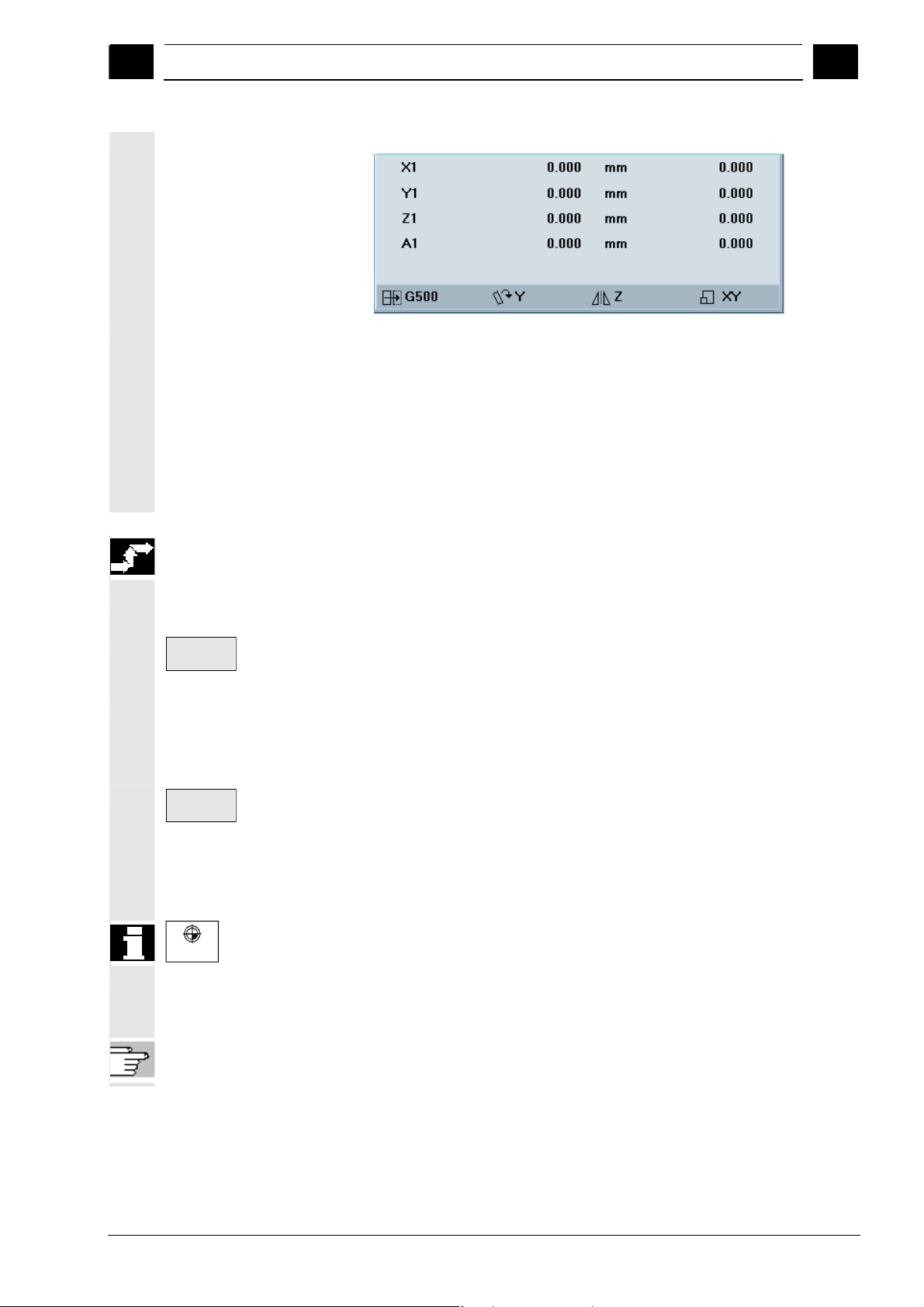
f
01/2008 Machine operating area
4
4.2 General functions and displays
4
The machine coordinate system comprises all the physically existing
Graphical display of the
active coordinate system
Meaning of the symbols
(from left to right):
Act. val.
MCS
Act. val.
WCS
WCS MCS
/PG/ Programming Manual Fundamentals
Example:
Display of the following transformations:
• Designation of the active work offset
(default value: G500).
• Rotation of the geometry axes involved. Without rotation the
symbol is invisible.
• Mirroring of the geometry axes involved. Without mirroring the
symbol is invisible.
• Scaling of the geometry axes involved. Without scaling the
symbol is invisible.
Sequence of operations
"JOG" mode is selected in the "Machine" operating area.
The actual values of the machine axes and their positions are
displayed. The softkey label changes to "Act. val. WCS".
machine axes. Reference points, tool and pallet change points are
defined in the Machine Coordinate System.
When you press the "Act. val. WCS" softkey, the geometry and
special axes plus their positions appear in the "Position" window.
The softkey label changes to "Act. val. MCS". The workpiece
coordinate system is assigned to a specific workpiece. Settings in the
NC program refer to the WCS.
• You can also toggle between the workpiece and machine
coordinate systems by pressing the "WCS/MCS" key on the MCP.
• The number of places displayed after the decimal point and units o
measurement can be set in machine data.
© Siemens AG 2008 All rights reserved.
SINUMERIK 840Di sl/840D sl/840D Operating Manual HMI-Advanced (BAD) - 01/2008 Edition 4-97
Page 98

Machine operating area 01/2008
4.2 General functions and displays
4
4.2.4 Displaying several transverse axes
Most lathes use one transverse axis in the channel. Special lathes
MD 30460: Bit2 = 0
One transverse axis
Several transverse axes
Function
with several transverse axes in the channel are also supported.
Dimensions can be entered and displayed for the diameter
simultaneously for known transverse axes in the channel.
Rotary axes are not permitted to serve as transverse axes.
The transverse axes are displayed in three statuses:
• Axis with constant cutting velocity (G96/G961/G962) where the
radius is displayed.
• Axis with constant cutting velocity and where the diameter actual
value is displayed.
• Axis where the actual diameter is displayed. Is displayed if the
values DIAMON or DIAM90 are active in group G29.
Constant cutting velocity (G96/G961/G962) is only possible for a
transverse axis as geometry axis. When using a transverse axis in the
channel – defined using the channel machine data MD 20100:
DIAMETER_AX_DEF – there are no changs regarding programming
and setting of the machine data.
The axis machine data MD 30460: BASE_FUNCTION_MASK bit 2
allows the definition of additional transverse axes, for which axisspecific diameter programming.
Axis-specific diameter programming not permitted.
Bit2 = 1
An axis can be simultaneously defined in MD 20100 and in MD 30460
bit2.
Axis-specific diameter programming permitted.
This setting is only permitted for linear axes (neither rotary
axes nor spindles).
4
4-98 SINUMERIK 840Di sl/840D sl/840D Operating Manual HMI-Advanced (BAD) - 01/2008 Edition
© Siemens AG 2008 All rights reserved.
Page 99

01/2008 Machine operating area
4
4.2 General functions and displays
4
Example
References
The axis Y is a transverse axis where the actual diameter is displayed
and axis Z is G96 transverse axis where the actual diameter is
displayed.
Actual value window in the machine operator area:
Programming Manual, Fundamentals “Special turning functions”
4.2.5 Displaying axis feedrates
Function
Axis
feedrate
or
In operating mode "JOG", "MDA" or "AUTO", you can display the
current feedrate, residual path information and the associated override
data.
Sequence of operations
"JOG" mode is selected in the "Machine" operating area.
Press the "Axis feedrate" softkey:
• With "Machine" the feed window is displayed with the current
feedrates and distance-to-go information as well as the associated
override.
• With "Work" the feed window for the axes taking part in the
interpolation is displayed with the current feed and the distanceto-go information with path override; for the remaining axes the
current feed and distance-to-go information is displayed with
single-axis override.
You can use the "Page" keys to display other axes if required.
© Siemens AG 2008 All rights reserved.
SINUMERIK 840Di sl/840D sl/840D Operating Manual HMI-Advanced (BAD) - 01/2008 Edition 4-99
Page 100

Machine operating area 01/2008
4.2 General functions and displays
4
4.2.6 Display G functions, transformations and swivel data
G-fct.+
Transf.
or
Function
Active G functions and transformations in the currently active channel
can be displayed.
Sequence of operations
"AUTO"/"MDA"/"JOG" mode is selected in the "Machine" operating
area.
The window "G Functions + Transformations" with the active G
functions and transformations is displayed.
Using the "Page" keys you can scroll up and down to display other G
functions.
Additional information
4
References
Swivel data status display Prerequisite:
References
Every G group has a fixed location. The group number (no.) and the
current G function of the G groups are displayed only if a G function is
active.
/PG/ Programming Manual, Fundamentals
The swivel function (CYCLE800) has been set up by the machine
manufacturer.
The active swivel data record (orientable toolholder TOOLCARRIER)
is displayed concurrently with the transformations.
The following values are displayed:
TCARR = 1 ... n* *n is the maximum number of swivel data items
that have been set up (TOOLCARRIER) and are
active.
/PGZ/ Programming Manual, Cycles: Chapter “Swiveling”
4-100 SINUMERIK 840Di sl/840D sl/840D Operating Manual HMI-Advanced (BAD) - 01/2008 Edition
© Siemens AG 2008 All rights reserved.
 Loading...