

Page 1

Guidelines for machine configuration
___________________
___________________
___________________
___________________
___________________
___________________
___________________
___________________
___________
___________________
___________________
___________________
___________________
___________________
SINUMERIK, SINAMICS
SINUMERIK 840D sl, SINAMICS
S120
Guidelines for machine
configuration
System Manual
Valid for NCU SW 4.5 SP1 and higher
MA 01/2013
6FC5397
Preface
Fundamental safety
instructions
1
System overview
2
SINUMERIK 840D sl
3
SINAMICS drive line-up
4
Communication within the
system
5
Line connection
6
DC link
7
Connection of the
components in SINAMICS
drive system
8
Safety Integrated
9
Signal Interconnection
10
Typical circuit diagrams
11
Activate/Deactivate Drive
System
12
Appendix
A
-6CP10-0BA2
Page 2

Siemens AG
Industry Sector
Postfach 48 48
90026 NÜRNBERG
GERMAN
Order number: 6FC5397-6CP10-0BA2
Ⓟ
Copyright © Siemens AG 2006 - 2013.
All rights reserved
Warning notice system
DANGER
indicates that death or severe personal injury will result if proper precautions are not taken.
WARNING
indicates that death or severe personal injury may result if proper precautions are not taken.
CAUTION
indicates that minor personal injury can result if proper precautions are not taken.
NOTICE
indicates that property damage can result if proper precautions are not taken.
Qualified Personnel
personnel qualified
Proper use of Siemens products
WARNING
Siemens products may only be used for the applications described in the catalog and in the relevant technical
maintenance are required to ensure that the products operate safely and without any problems. The permissible
ambient conditions must be complied with. The information in the relevant documentation must be observed.
Trademarks
Disclaimer of Liability
Legal information
This manual contains notices you have to observe in order to ensure your personal safety, as well as to prevent
damage to property. The notices referring to your personal safety are highlighted in the manual by a safety alert
symbol, notices referring only to property damage have no safety alert symbol. These notices shown below are
graded according to the degree of danger.
If more than one degree of danger is present, the warning notice representing the highest degree of danger will
be used. A notice warning of injury to persons with a safety alert symbol may also include a warning relating to
property damage.
The product/system described in this documentation may be operated only by
task in accordance with the relevant documentation, in particular its warning notices and safety instructions.
Qualified personnel are those who, based on their training and experience, are capable of identifying risks and
avoiding potential hazards when working with these products/systems.
for the specific
Note the following:
documentation. If products and components from other manufacturers are used, these must be recommended
or approved by Siemens. Proper transport, storage, installation, assembly, commissioning, operation and
All names identified by ® are registered trademarks of Siemens AG. The remaining trademarks in this publication
may be trademarks whose use by third parties for their own purposes could violate the rights of the owner.
We have reviewed the contents of this publication to ensure consistency with the hardware and software
described. Since variance cannot be precluded entirely, we cannot guarantee full consistency. However, the
information in this publication is reviewed regularly and any necessary corrections are included in subsequent
editions.
Y
11/2013 Technical data subject to change
Page 3

Preface
SINUMERIK/SINAMICS documentation
Further information
My Documentation Manager
Training
FAQs
Product
Support
The SINUMERIK and SINAMICS documentation is organized in the following categories:
● General documentation
● User documentation
● Manufacturer/service documentation
Click the following link to find information on the the following topics:
● Ordering documentation/overview of documentation
● Additional links to download documents
● Using documentation online (finding and searching in manuals/information)
http://www.siemens.com/motioncontrol/docu
Please send any questions about the technical documentation (e.g. suggestions for
improvement, corrections) to the following email address:
docu.motioncontrol@siemens.com
Using the following link, you can find information on how to create your own individual
documentation based on Siemens' content, and adapt it for your own machine
documentation:
http://www.siemens.com/mdm
Using the following link, you can find information on SITRAIN - training from Siemens for
products, systems and automation engineering solutions:
http://www.siemens.com/sitrain
You can find Frequently Asked Questions in the Service&Support pages under
http://support.automation.siemens.com
:
Guidelines for machine configuration
System Manual, MA 01/2013, 6FC5397-6CP10-0BA2
3
Page 4

Preface
Target group
Use and standard scope
Utilization phases and the available tools/documents
Utilization phase
Tools
Orientation
SINAMICS S sales documentation
This manual is intended for experienced drive and CNC configuration engineers. Its purpose
is to give you a compact guide to integrating the components of SINAMICS S120 and
SINUMERIK 840D sl.
This document supplements product-related equipment, software installation, and function
manuals for SINAMICS S120 and SINUMERIK 840D sl. It shows examples of the
mechanical layout of components, functional integration, as well as logical connections to the
signal interfaces of a processing machine.
This documentation is limited to the following series or functions:
● SINUMERIK 840D sl Type 1B (NCU 7x0.3, NX1x.3)
● SINAMICS in booksize format
● Communication between SINUMERIK NCU and the SINAMICS drives (communication
with operating, programming, and visualization units is not part of this documentation)
For reasons of clarity, this documentation does not contain all of the detailed information on
all of the product types. It also cannot take into consideration every conceivable type of
installation, operation, and service/maintenance. If you have any questions that go beyond
the scope of the information provided here, please contact your local representative.
Where necessary for the understanding and for important general conditions, this guide
contains extracts from the product manuals listed below. You can find there detailed
descriptions for the product-internal functions and properties, and for the mechanical and
electrical user interfaces.
Table 1 Utilization phases and the available tools/documents
Planning/engineering
Decision making/ordering SINAMICS S120 catalogs
• SIZER configuration tool
• Configuration manuals, motors
• SIMOTION, SINAMICS S120 and Motors for Production Machines
(Catalog PM 21)
• SINAMICS and Motors for Single-Axis Drives (catalog D 31)
• SINUMERIK 840D sl Type 1B
Equipment for Machine Tools (Catalog NC 62)
Guidelines for machine configuration
4 System Manual, MA 01/2013, 6FC5397-6CP10-0BA2
Page 5

Preface
Utilization phase
Tools
Functionality
Technical Support
SINUMERIK
Configuring/installation
Commissioning
Using/operating
Maintenance/Service
References
• SINAMICS S120 Equipment Manual for Control Units and Additional
System Components
• SINAMICS S120 Booksize Power Units Equipment Manual
• SINAMICS S120 Chassis Power Units Equipment Manual
• SINAMICS S120 Equipment Manual Liquid Cooled Chassis Power
Units
• SINAMICS S120 Equipment Manual for AC Drives
• SINAMICS S120M Equipment Manual Distributed Drive Technology
• SINUMERIK 840D sl Equipment Manual NCU 7x0.3 PN
• STARTER commissioning tool
• SIMATIC S7 Manager
• SINAMICS S120 Getting Started
• SINAMICS S120 Commissioning Manual
• SINAMICS S120 CANopen Commissioning Manual
• SINAMICS S120 Function Manual
• SINAMICS S120 Safety Integrated Function Manual
• SINAMICS S120/S150 List Manual
• SINUMERIK 840D sl Commissioning Manual CNC: NCK, PLC, drive
• SINUMERIK 840D sl Safety Integrated Function Manual
• SINAMICS S120 Commissioning Manual
• SINAMICS S120/S150 List Manual
• SINAMICS S120 Commissioning Manual
• SINAMICS S120/S150 List Manual
• SINAMICS S120/S150 List Manual
This documentation may also mention components that have not been released for use with
SINUMERIK 840D sl. The NC62 catalog is binding for the permitted combinations.
Country-specific telephone numbers for technical support are provided on the Internet under
Contact:
http://support.automation.siemens.com
You can find information on SINUMERIK at:
http://www.siemens.com/sinumerik
Guidelines for machine configuration
System Manual, MA 01/2013, 6FC5397-6CP10-0BA2
5
Page 6

Preface
SINAMICS
EC Declarations of Conformity
15257461
You can find information on SINAMICS at:
http://www.siemens.com/sinamics
The EC Declaration of Conformity for the EMC Directive can be found on the Internet at:
http://support.automation.siemens.com
Enter there the number
as a search term or contact your local Siemens office.
Guidelines for machine configuration
6 System Manual, MA 01/2013, 6FC5397-6CP10-0BA2
Page 7

Table of contents
Preface ................................................................................................................................................... 3
1 Fundamental safety instructions ............................................................................................................ 15
2 System overview ................................................................................................................................... 21
3 SINUMERIK 840D sl ............................................................................................................................. 33
4 SINAMICS drive line-up ........................................................................................................................ 55
1.1 General safety instructions .......................................................................................................... 15
1.2 Safety instructions for electromagnetic fields (EMF) ................................................................... 18
1.3 Handling electrostatic sensitive devices (ESD) ........................................................................... 18
1.4 Residual risks of power drive systems ......................................................................................... 19
2.1 Application .................................................................................................................................... 21
2.2 System configuration ................................................................................................................... 22
2.3 Variants ........................................................................................................................................ 24
2.4 SINAMICS S120 / SINUMERIK 840D sl Component Overview .................................................. 25
2.5 User interface software (HMI software) ....................................................................................... 30
2.6 Function of installation altitude and ambient temperature ........................................................... 32
3.1 Control Unit NCU 7x0.3 PN ......................................................................................................... 33
3.1.1 Description ................................................................................................................................... 33
3.1.2 Interface description ..................................................................................................................... 34
3.1.3 Interfaces and their terminal assignments ................................................................................... 35
3.1.3.1 DRIVE-CLiQ interfaces X100-X105 (X103) ................................................................................. 35
3.1.3.2 Digital inputs/outputs X122, X132 and X142 ............................................................................... 37
3.1.3.3 PROFINET interface X150 P1, P2 ............................................................................................... 40
3.1.3.4 PROFIBUS interface X126 .......................................................................................................... 41
3.1.4 LED displays ................................................................................................................................ 43
3.2 NX1x.3 extension units ................................................................................................................ 45
3.2.1 Description ................................................................................................................................... 45
3.2.2 Representation of the NX1x.3 ...................................................................................................... 46
3.2.3 Interfaces and their terminal assignments ................................................................................... 48
3.2.3.1 X122 digital inputs/outputs ........................................................................................................... 48
3.2.4 NX1x3 wiring ................................................................................................................................ 50
3.3 Option Board CBE30-2 ................................................................................................................ 52
3.3.1 Description ................................................................................................................................... 52
4.1 Structure of the drive line-up ........................................................................................................ 55
4.1.1 Description ................................................................................................................................... 55
4.1.2 Single row layout .......................................................................................................................... 57
4.1.3 Two-row/Multiple-row construction .............................................................................................. 59
4.1.4 Center infeed (single row construction) for 16 to 120 kW Line Modules ..................................... 62
Guidelines for machine configuration
System Manual, MA 01/2013, 6FC5397-6CP10-0BA2
7
Page 8

Table of contents
5 Communication within the system ......................................................................................................... 95
6 Line connection .................................................................................................................................... 107
4.1.5 Distributed configuration ............................................................................................................. 63
4.2 Connection of the SINUMERIK components .............................................................................. 66
4.2.1 Layout and fastening of the NCU/NX modules ........................................................................... 66
4.2.2 Layout of the NX for single row construction integrated in the power unit group ....................... 67
4.2.3 NCU/NX layout as offset solution ................................................................................................ 68
4.2.4 Direct installation of a CU-/NCU-/NX module on the Line Module.............................................. 68
4.3 Shield Connection ....................................................................................................................... 69
4.3.1 SINAMICS Components Dimension Drawings (Internal Air Cooling) ......................................... 69
4.3.2 SINAMICS Components Dimension Drawings (External Air Cooling) ........................................ 73
4.3.3 Shield Connection for Internal Heat Dissipation ......................................................................... 77
4.4 Note for the installation clearance for the connection cables ..................................................... 78
4.4.1 General information ..................................................................................................................... 78
4.4.2 Clearance of the Power Components ......................................................................................... 79
4.4.3 Ventilation Clearances of the SINUMERIK Components ........................................................... 79
4.5 Heat Dissipation of the Control Cabinet ...................................................................................... 80
4.5.1 Control cabinet cooling options ................................................................................................... 80
4.5.2 General information on ventilation .............................................................................................. 81
4.5.3 Cooling clearances ...................................................................................................................... 83
4.5.4 Dimensioning Climate Control Equipment .................................................................................. 89
4.6 Cooling of power units ................................................................................................................. 90
4.6.1 Internal Air Cooling ...................................................................................................................... 90
4.6.2 External Air Cooling .................................................................................................................... 91
4.6.3 Cold plate cooling ........................................................................................................................ 92
4.6.4 Liquid cooling (liquid cooled) ....................................................................................................... 94
5.1 Communication overview ............................................................................................................ 95
5.2 DRIVE-CLiQ Topologies ............................................................................................................. 99
5.2.1 DRIVE-CLiQ topology ................................................................................................................. 99
5.2.2 DRIVE-CLiQ wiring ................................................................................................................... 101
6.1 Power Supply Interface Variants ............................................................................................... 107
6.1.1 Ways of connecting the line supply ........................................................................................... 107
6.1.2 Operation of the line connection components on the supply network ...................................... 108
6.1.3 Operating line connection components via an autotransformer ............................................... 109
6.1.4 Operating line connection components via an isolating transformer ........................................ 110
6.1.5 Residual-current operated circuit breakers (RCD) .................................................................... 112
6.1.6 Residual-current monitors (RCM) ............................................................................................. 114
6.2 Overcurrent protection by means of line fuses and circuit breakers ......................................... 116
6.3 Line Contactor Control .............................................................................................................. 117
6.3.1 Line contactor control for Line Modules without DRIVE-CLiQ interface (5 kW and 10 kW
versions) .................................................................................................................................... 118
6.3.2 Line Contactor Control for Line Modules with DRIVE-CLiQ Interface ...................................... 120
6.3.3 Line Contactor Control Commissioning using an Example ....................................................... 121
6.4 Line filters .................................................................................................................................. 123
6.4.1 Safety instructions for line filters ............................................................................................... 123
6.4.2 Overview of line filters ............................................................................................................... 125
Guidelines for machine configuration
8 System Manual, MA 01/2013, 6FC5397-6CP10-0BA2
Page 9

Table of contents
7 DC link ................................................................................................................................................ 159
8 Connection of the components in SINAMICS drive system .................................................................. 167
6.4.3 Wideband Filter for Active Line Modules ................................................................................... 126
6.4.4 Basic Line Filters for Active Line Modules ................................................................................. 127
6.4.5 Basic Line Filter for Smart Line Modules ................................................................................... 128
6.5 Active Interface Module (AIM) .................................................................................................... 129
6.5.1 Description ................................................................................................................................. 129
6.5.2 Safety instructions for Active Interface Modules ........................................................................ 130
6.5.3 Interface description ................................................................................................................... 132
6.5.3.1 Overview .................................................................................................................................... 132
6.5.3.2 Line/load connection .................................................................................................................. 136
6.5.3.3 X121 temperature sensor and fan control ................................................................................. 136
6.5.3.4 Electronics power supply X124 .................................................................................................. 137
6.5.4 Operation on an isolated-neutral system (IT system) ................................................................ 137
6.5.4.1 IT systems .................................................................................................................................. 137
6.5.4.2 Operating an Active Interface Module on an isolated-neutral line supply (IT line supply) ......... 138
6.5.5 Connection example .................................................................................................................. 139
6.5.6 Technical data ............................................................................................................................ 140
6.6 Line reactors .............................................................................................................................. 141
6.6.1 Safety instructions for line reactors ............................................................................................ 141
6.6.2 HFD line reactors for Active Line Module .................................................................................. 142
6.6.2.1 Description ................................................................................................................................. 142
6.6.2.2 Interface description ................................................................................................................... 143
6.6.2.3 Dimension drawings ................................................................................................................... 146
6.6.2.4 Technical data ............................................................................................................................ 151
6.6.3 Line reactors for Smart Line Modules ........................................................................................ 152
6.6.3.1 Interface description ................................................................................................................... 152
6.6.3.2 Dimension drawings ................................................................................................................... 154
6.6.3.3 Technical data ............................................................................................................................ 157
6.7 Possible combinations of line reactors and line filters ............................................................... 158
7.1 Function of the DC link ............................................................................................................... 159
7.2 DC link components ................................................................................................................... 159
7.2.1 Braking Module .......................................................................................................................... 160
7.2.2 Capacitor Module ....................................................................................................................... 161
7.3 Current Carrying Capacity of the DC Link Busbar ..................................................................... 161
7.4 DC link rectifier adapter ............................................................................................................. 164
7.5 DC link adapter .......................................................................................................................... 165
8.1 Electronics Power Supply .......................................................................................................... 167
8.1.1 External power supply (SITOP) ................................................................................................. 167
8.1.1.1 Selection of the Power Supply Devices ..................................................................................... 168
8.1.1.2 24 V current consumption of the components ........................................................................... 169
8.1.1.3 Calculation of the 24 VDC Power Requirement Example ......................................................... 171
8.1.1.4 Assignment of the power supply to other components .............................................................. 172
8.1.1.5 Overcurrent protection ............................................................................................................... 174
8.1.1.6 Line formation ............................................................................................................................ 175
8.1.1.7 Power Supply Connection Example........................................................................................... 177
8.1.2 Internal power supply via the Control Supply Module (CSM) .................................................... 178
Guidelines for machine configuration
System Manual, MA 01/2013, 6FC5397-6CP10-0BA2
9
Page 10

Table of contents
8.1.2.1 Connection ................................................................................................................................ 180
8.1.2.2 Single operation ........................................................................................................................ 181
8.1.2.3 Parallel operation ...................................................................................................................... 182
8.2 Connection of a SINAMICS Control Unit CU320-2 ................................................................... 187
8.3 Connection of line modules ....................................................................................................... 189
8.3.1 Introduction................................................................................................................................ 189
8.3.2 Safety instructions for Line Modules Booksize ......................................................................... 192
8.3.3 Active Line Modules with internal air cooling ............................................................................ 197
8.3.3.1 Description ................................................................................................................................ 197
8.3.3.2 Interface description .................................................................................................................. 198
8.3.3.3 Connection example ................................................................................................................. 203
8.3.3.4 Meaning of LEDs ....................................................................................................................... 204
8.3.3.5 Dimension drawings .................................................................................................................. 205
8.3.3.6 Installation ................................................................................................................................. 209
8.3.3.7 Technical specifications ............................................................................................................ 211
8.3.4 Active Line Modules with external air cooling ........................................................................... 217
8.3.4.1 Description ................................................................................................................................ 217
8.3.4.2 Interface description .................................................................................................................. 218
8.3.4.3 Connection example ................................................................................................................. 223
8.3.4.4 Meaning of LEDs ....................................................................................................................... 224
8.3.4.5 Dimension drawings .................................................................................................................. 225
8.3.4.6 Installation ................................................................................................................................. 228
8.3.4.7 Technical data ........................................................................................................................... 234
8.3.5 Active Line Modules with cold plate .......................................................................................... 240
8.3.5.1 Description ................................................................................................................................ 240
8.3.5.2 Interface description .................................................................................................................. 241
8.3.5.3 Connection example ................................................................................................................. 245
8.3.5.4 Meaning of LEDs ....................................................................................................................... 246
8.3.5.5 Dimension drawings .................................................................................................................. 247
8.3.5.6 Installation ................................................................................................................................. 249
8.3.5.7 Technical specifications ............................................................................................................ 252
8.3.6 Active Line Modules Liquid Cooled ........................................................................................... 257
8.3.6.1 Description ................................................................................................................................ 257
8.3.6.2 Interface description .................................................................................................................. 258
8.3.6.3
Connection example ................................................................................................................. 262
8.3.6.4 Meaning of LEDs ....................................................................................................................... 263
8.3.6.5 Dimension drawing .................................................................................................................... 264
8.3.6.6 Installation ................................................................................................................................. 265
8.3.6.7 Technical specifications ............................................................................................................ 266
8.3.7 Smart Line Modules with internal air cooling ............................................................................ 270
8.3.7.1 Description ................................................................................................................................ 270
8.3.7.2 Product-specific safety information for the Smart Line Modules in booksize format ................ 271
8.3.7.3 Interface description .................................................................................................................. 273
8.3.7.4 Connection examples ................................................................................................................ 283
8.3.7.5 Meaning of LEDs ....................................................................................................................... 285
8.3.7.6 Dimension drawings .................................................................................................................. 287
8.3.7.7 Installation ................................................................................................................................. 291
8.3.7.8 Technical specifications ............................................................................................................ 292
8.3.8 Smart Line Modules with external air cooling ........................................................................... 295
8.3.8.1 Description ................................................................................................................................ 295
8.3.8.2 Product-specific safety information for the Smart Line Modules in booksize format ................ 296
Guidelines for machine configuration
10 System Manual, MA 01/2013, 6FC5397-6CP10-0BA2
Page 11

Table of contents
8.3.8.3 Interface description ................................................................................................................... 298
8.3.8.4 Connection examples ................................................................................................................ 308
8.3.8.5 Meaning of LEDs........................................................................................................................ 310
8.3.8.6 Dimension drawings ................................................................................................................... 312
8.3.8.7 Installation .................................................................................................................................. 316
8.3.8.8 Technical specifications ............................................................................................................. 321
8.3.9 Smart Line Modules with cold plate ........................................................................................... 324
8.3.9.1 Description ................................................................................................................................. 324
8.3.9.2 Product-specific safety information for the Smart Line Modules in booksize format ................. 325
8.3.9.3 Interface description ................................................................................................................... 327
8.3.9.4 Connection example .................................................................................................................. 331
8.3.9.5 Meaning of LEDs........................................................................................................................ 332
8.3.9.6 Dimension drawings ................................................................................................................... 333
8.3.9.7 Installation .................................................................................................................................. 334
8.3.9.8 Technical data ............................................................................................................................ 336
8.4 Connection of motor modules .................................................................................................... 341
8.4.1 Safety instructions for Motor Modules Booksize ........................................................................ 341
8.4.2 Motor Modules with internal air cooling ..................................................................................... 345
8.4.2.1 Description ................................................................................................................................. 345
8.4.2.2 Interface description ................................................................................................................... 346
8.4.2.3 Connection examples ................................................................................................................ 353
8.4.2.4 Meaning of LEDs........................................................................................................................ 355
8.4.2.5 Dimension drawings ................................................................................................................... 356
8.4.2.6 Installation .................................................................................................................................. 361
8.4.2.7 Technical specifications ............................................................................................................. 363
8.4.3 Motor Module with external air cooling ...................................................................................... 369
8.4.3.1 Description ................................................................................................................................. 369
8.4.3.2 Interface description ................................................................................................................... 370
8.4.3.3 Connection examples ................................................................................................................ 377
8.4.3.4 Meaning of LEDs........................................................................................................................ 379
8.4.3.5 Dimension drawings ................................................................................................................... 380
8.4.3.6 Mounting .................................................................................................................................... 385
8.4.3.7 Technical data ............................................................................................................................ 392
8.4.4 Motor Modules with cold plate ................................................................................................... 398
8.4.4.1 Description .................................................................................................................................
398
8.4.4.2 Interface description ................................................................................................................... 399
8.4.4.3 Connection examples ................................................................................................................ 405
8.4.4.4 Meaning of LEDs........................................................................................................................ 407
8.4.4.5 Dimension drawings ................................................................................................................... 408
8.4.4.6 Mounting .................................................................................................................................... 412
8.4.4.7 Technical specifications ............................................................................................................. 415
8.4.5 Motor Modules Liquid Cooled .................................................................................................... 421
8.4.5.1 Description ................................................................................................................................. 421
8.4.5.2 Interface description ................................................................................................................... 422
8.4.5.3 Connection example .................................................................................................................. 426
8.4.5.4 Meaning of LEDs........................................................................................................................ 427
8.4.5.5 Dimension drawing .................................................................................................................... 428
8.4.5.6 Installation .................................................................................................................................. 429
8.4.5.7 Technical specifications ............................................................................................................. 430
8.5 DRIVE-CLiQ Hub Modules (DMC20, DME20) ........................................................................... 435
8.5.1 DMC20 ....................................................................................................................................... 435
Guidelines for machine configuration
System Manual, MA 01/2013, 6FC5397-6CP10-0BA2
11
Page 12

Table of contents
8.5.1.1 Description ................................................................................................................................ 435
8.5.1.2 Overview ................................................................................................................................... 435
8.5.1.3 Electronics power supply X524 ................................................................................................. 436
8.5.1.4 DRIVE-CLiQ interface ............................................................................................................... 436
8.5.1.5 Significance of the LED on the DMC20 .................................................................................... 437
8.5.1.6 Dimension drawing .................................................................................................................... 437
8.5.1.7 Technical data ........................................................................................................................... 438
8.5.2 DME20 ...................................................................................................................................... 438
8.5.2.1 Description ................................................................................................................................ 438
8.5.2.2 Safety information ..................................................................................................................... 438
8.5.2.3 Overview ................................................................................................................................... 439
8.5.2.4 Electronics power supply X524 ................................................................................................. 440
8.5.2.5 DRIVE-CLiQ interface ............................................................................................................... 440
8.5.2.6 Cable lengths ............................................................................................................................ 441
8.5.2.7 Specifications for use with UL approval .................................................................................... 441
8.5.2.8 Dimension drawing .................................................................................................................... 443
8.5.2.9 Installation ................................................................................................................................. 444
8.5.2.10 Technical data ........................................................................................................................... 444
8.6 Connecting Terminal Modules .................................................................................................. 445
8.6.1 TM15: Terminal expansion for digital inputs/outputs ................................................................ 445
8.6.2 TM41: Emulating an incremental encoder ................................................................................ 445
8.6.3 TM120: DRIVE-CLiQ component for temperature evaluation with safe electrical
separation.................................................................................................................................. 446
8.7 Sensor Systems Connection ..................................................................................................... 447
8.7.1 Introduction................................................................................................................................ 447
8.7.2 Overview of Sensor Modules .................................................................................................... 448
8.7.3 X200-X203 DRIVE-CLiQ interface ............................................................................................ 450
8.7.4 Examples of encoder connections ............................................................................................ 451
8.8 Motor Connection ...................................................................................................................... 452
8.8.1 Motor connection plug ............................................................................................................... 452
8.8.1.1 Introducing the motor connector ............................................................................................... 452
8.8.1.2 Installation of the motor connection plug with locking mechanism ........................................... 452
8.8.1.3 Installation of the motor connection plug with screwed joint ..................................................... 455
8.8.1.4 Removing the motor connector plug from prefabricated power cables .................................... 456
8.8.2 Brake connection ...................................................................................................................... 457
8.8.2.1 General Notes ................................
........................................................................................... 457
8.8.2.2 Motor and brake connection...................................................................................................... 457
8.8.2.3 Connection of the Brake Directly on the Motor Module ............................................................ 459
8.8.2.4 Connection of the Brake using Interface Relay......................................................................... 460
8.8.2.5 Brake Control ............................................................................................................................ 461
8.8.3 X21/X22 EP terminals / temperature sensor Motor Module ..................................................... 466
8.9 Voltage Protection Module (VPM), external .............................................................................. 467
8.10 Cables ....................................................................................................................................... 471
8.10.1 General information ................................................................................................................... 471
8.10.2 Cable shielding and routing....................................................................................................... 471
8.10.3 Equipotential Bonding ............................................................................................................... 473
8.10.4 Protective Ground Connection .................................................................................................. 473
8.10.5 Maximum cable lengths ............................................................................................................ 474
8.11 DRIVE-CLiQ cabinet bushings .................................................................................................. 475
Guidelines for machine configuration
12 System Manual, MA 01/2013, 6FC5397-6CP10-0BA2
Page 13

Table of contents
9 Safety Integrated ................................................................................................................................. 483
10 Signal Interconnection ......................................................................................................................... 503
11 Typical circuit diagrams ....................................................................................................................... 505
12 Activate/Deactivate Drive System ........................................................................................................ 507
A Appendix............................................................................................................................................. 513
Index................................................................................................................................................... 531
8.11.1 Description ................................................................................................................................. 475
8.11.2 Interface description ................................................................................................................... 476
8.11.2.1 Overview .................................................................................................................................... 476
8.11.3 Dimension drawings ................................................................................................................... 477
8.11.4 Installation .................................................................................................................................. 478
8.11.4.1 DRIVE-CLiQ cabinet bushing for cables with RJ45 connectors ................................................ 478
8.11.4.2 DRIVE-CLiQ cabinet bushing for cables with M12 plug/socket ................................................. 480
8.11.5 Technical data ............................................................................................................................ 481
9.1 Safety Integrated terminology .................................................................................................... 483
9.2 SINAMICS Safety Integrated ..................................................................................................... 485
9.2.1 Safety functions.......................................................................................................................... 485
9.2.2 Basic Functions .......................................................................................................................... 486
9.2.2.1 Safe Torque Off (STO) ............................................................................................................... 486
9.2.2.2 Safe Stop 1 (SS1) ...................................................................................................................... 494
9.2.2.3 Safe Brake Control (SBC) .......................................................................................................... 495
9.3 SINUMERIK Safety Integrated ................................................................................................... 497
9.3.1 Safety functions.......................................................................................................................... 497
9.3.2 Connecting safe sensors and actuators to the SINUMERIK ..................................................... 498
12.1 Overview of the Status Signals .................................................................................................. 507
12.2 Drive Group with Several Axes .................................................................................................. 508
A.1 Screw terminals.......................................................................................................................... 513
A.2 Spring-loaded terminals ............................................................................................................. 515
A.3 Power loss of components ......................................................................................................... 516
A.3.1 Power Loss of the SINUMERIK Components ............................................................................ 516
A.3.2 Power loss of SINAMICS components ...................................................................................... 516
A.3.2.1 Power loss for Control Units, Sensor Modules, and other system components ........................ 516
A.3.2.2 Power loss for line filters and line reactors ................................................................................ 517
A.3.2.3 Power loss for power units with internal air cooling ................................................................... 518
A.3.2.4 Power loss for power units with external air cooling .................................................................. 520
A.3.2.5 Power loss for power units with cold plate ................................................................................. 521
A.3.2.6 Power loss for liquid-cooled power units ................................................................................... 522
A.3.3 Electronics losses of power units ............................................................................................... 523
A.3.4 Losses for power units in the partial load range ........................................................................ 525
A.3.5 Typical power losses for Motor Modules ................................................................................... 526
A.4 Abbreviations ............................................................................................................................. 528
Guidelines for machine configuration
System Manual, MA 01/2013, 6FC5397-6CP10-0BA2
13
Page 14

Table of contents
Guidelines for machine configuration
14 System Manual, MA 01/2013, 6FC5397-6CP10-0BA2
Page 15
1
1.1
General safety instructions
DANGER
Danger to life when live parts are touched
WARNING
Danger to life through a hazardous voltage when connecting an unsuitable power supply
Death or serious injury can result when live parts are touched.
• Only work on electrical devices when you are qualified for this job.
• Always observe the country-specific safety rules.
Generally, six steps apply when establishing safety:
1. Prepare for shutdown and notify all those who will be affected by the procedure.
2. Disconnect the machine from the supply.
– Switch off the machine.
– Wait until the discharge time specified on the warning labels has elapsed.
– Check that it really is in a no-voltage condition, from phase conductor to phase
conductor and phase conductor to protective conductor.
– Check whether the existing auxiliary supply circuits are de-energized.
– Ensure that the motors cannot move.
3. Identify all other hazardous energy sources, e.g. compressed air, hydraulic systems,
water.
4. Isolate or neutralize all hazardous energy sources, e.g. by closing switches, grounding
or short-circuiting or closing valves.
5. Secure the energy sources against switching on again.
6. Make sure that the right machine is completely locked.
After you have completed the work, restore the operational readiness in the inverse
Guidelines for machine configuration
System Manual, MA 01/2013, 6FC5397-6CP10-0BA2
sequence.
Death or serious injury can result when live parts are touched in the event of a fault.
• Only use power supplies that provide SELV (Safety Extra Low Voltage) or PELV-
(Protective Extra Low Voltage) output voltages for all connections and terminals of the
electronics modules.
15
Page 16
Fundamental safety instructions
WARNING
Danger to life when live parts are touched on damaged devices
WARNING
Danger of fire spreading due to inadequate housing
WARNING
Danger to life through unexpected movement of machines when using mobile wireless
devices or mobile phones
WARNING
Fire hazard for the motor due to overload of the insulation
1.1 General safety instructions
Improper handling of devices can cause damage.
Hazardous voltages can be present at the housing or exposed components on damaged
devices.
• Ensure compliance with the limit values specified in the technical data during transport,
storage and operation.
• Do not use any damaged devices.
• Protect the components against conductive pollution, e.g., by installing them in a control
cabinet with IP54 degree of protection according to IEC 60529 or NEMA 12. Provided
conductive pollution can be prevented at the installation site, the degree of protection for
the cabinet can be decreased accordingly.
Fire and smoke development can cause severe personal injury or material damage.
• Install devices without a protective housing in a metal control cabinet (or protect the
device by another equivalent measure) in such a way that contact with fire inside and
outside the device is prevented.
• Additionally, select the installation site so that an uncontrolled spreading of smoke can
be avoided in the case of a fire.
• Ensure that smoke can escape via designated paths.
Using mobile wireless devices or mobile phones with a transmitter power > 1 W closer than
approx. 2 m to the components may cause the devices to malfunction and influence the
functional safety of machines, therefore putting people at risk or causing material damage.
• Switch the wireless devices or mobile phones off in the immediate vicinity of the
components.
There is a greater load on the motor insulation through a ground fault in an IT system. A
possible result is the failure of the insulation with a risk for personnel through smoke
development and fire.
• Use a monitoring device that signals an insulation fault.
• Correct the fault as quickly as possible so the motor insulation is not overloaded.
Guidelines for machine configuration
16 System Manual, MA 01/2013, 6FC5397-6CP10-0BA2
Page 17
Fundamental safety instructions
WARNING
Fire hazard due to overheating because of inadequate ventilation clearances
WARNING
Danger to life through electric shock due to unconnected cable shields
WARNING
Danger to life when safety functions are inactive
Note
Important safety notices for safety functions
If you want to use sa
manuals.
1.1 General safety instructions
Inadequate ventilation clearances can cause overheating with a risk for personnel through
smoke development and fire. This can also result in increased downtime and reduced
service lives for devices / systems.
• Ensure compliance with the specified minimum clearance as ventilation clearance for
the respective component. They can be found in the dimension drawings or in the
"Product-specific safety instructions" at the start of the respective section.
Hazardous touch voltages can occur through capacitive cross-coupling due to unconnected
cable shields.
• Connect cable shields and unused conductors of power cables (e.g., brake conductors)
at least on one side to the grounded housing potential.
Safety functions that are inactive or that have not been adjusted accordingly can cause
operational faults on machines that could lead to serious injury or death.
• Observe the information in the appropriate product documentation before
commissioning.
• Carry out a safety inspection for functions relevant to safety on the entire system,
including all safety-related components.
• Ensure that the safety functions used in your drives and automation tasks are adjusted
and activated through appropriate parameterizing
• Run a function test.
• Only put your plant into live operation once you have guaranteed that the functions
relevant to safety are running correctly.
fety functions, you must observe the safety notices in the safety
Guidelines for machine configuration
System Manual, MA 01/2013, 6FC5397-6CP10-0BA2
17
Page 18
Fundamental safety instructions
1.2
Safety instructions for electromagnetic fields (EMF)
WARNING
Danger to life from electromagnetic fields
1.3
Handling electrostatic sensitive devices (ESD)
NOTICE
Damage through electric fields or electrostatic discharge
1.2 Safety instructions for electromagnetic fields (EMF)
Electromagnetic fields (EMF) are generated by the operation of electrical power equipment
such as transformers, converters or motors.
People with pacemakers or implants are at a special risk in the immediate vicinity of these
devices/systems.
• Keep a distance of at least 2 m.
Electrostatic sensitive devices (ESD) are individual components, integrated circuits, modules
or devices that may be damaged by either electric fields or electrostatic discharge.
Electric fields or electrostatic discharge can cause malfunctions through damaged
individual components, integrated circuits, modules or devices.
• Only pack, store, transport and send electronic components, modules or devices in their
original packaging or in other suitable materials, e.g conductive foam rubber of
aluminum foil.
• Only touch components, modules and devices when you are grounded by one of the
following methods:
– Wearing an ESD wrist strap
– Wearing ESD shoes or ESD grounding straps in ESD areas with conductive flooring
• Only place electronic components, modules or devices on conductive surfaces (table
with ESD surface, conductive ESD foam, ESD packaging, ESD transport container).
Guidelines for machine configuration
18 System Manual, MA 01/2013, 6FC5397-6CP10-0BA2
Page 19

Fundamental safety instructions
1.4
Residual risks of power drive systems
Residual risks of power drive systems
1.4 Residual risks of power drive systems
The control and drive components of a drive system are approved for industrial and
commercial use in industrial line supplies. Their use in public line supplies requires a
different configuration and/or additional measures.
These components may only be operated in closed housings or in higher-level control
cabinets with protective covers that are closed, and when all of the protective devices are
used.
These components may only be handled by qualified and trained technical personnel who
are knowledgeable and observe all of the safety instructions on the components and in the
associated technical user documentation.
When assessing the machine's risk in accordance with the respective local regulations (e.g.,
EC Machinery Directive), the machine manufacturer must take into account the following
residual risks emanating from the control and drive components of a drive system:
1. Unintentional movements of driven machine components during commissioning,
operation, maintenance, and repairs caused by, for example:
– Hardware defects and/or software errors in the sensors, controllers, actuators, and
connection technology
– Response times of the controller and drive
– Operating and/or ambient conditions outside of the specification
– Condensation / conductive contamination
– Parameterization, programming, cabling, and installation errors
– Use of radio devices / cellular phones in the immediate vicinity of the controller
– External influences / damage
2. In the event of a fault, exceptionally high temperatures, including an open fire, as well as
emissions of light, noise, particles, gases, etc. can occur inside and outside the inverter,
e.g.:
– Component malfunctions
– Software errors
– Operating and/or ambient conditions outside of the specification
– External influences / damage
Inverters of the Open Type / IP20 degree of protection must be installed in a metal control
cabinet (or protected by another equivalent measure) such that the contact with fire inside
and outside the inverter is not possible.
Guidelines for machine configuration
System Manual, MA 01/2013, 6FC5397-6CP10-0BA2
19
Page 20

Fundamental safety instructions
Note
The components must be protected against conductive contamination (e.g. by installing them
in a control cabinet with degree of protection IP54 according to IEC 60529 or NEMA 12).
Assuming that conductive contamination at the installation site
lower degree of cabinet protection may be permitted.
1.4 Residual risks of power drive systems
3. Hazardous shock voltages caused by, for example:
– Component malfunctions
– Influence of electrostatic charging
– Induction of voltages in moving motors
– Operating and/or ambient conditions outside of the specification
– Condensation / conductive contamination
– External influences / damage
4. Electrical, magnetic and electromagnetic fields generated in operation that can pose a
risk to people with a pacemaker, implants or metal replacement joints, etc. if they are too
close.
5. Release of environmental pollutants or emissions as a result of improper operation of the
system and/or failure to dispose of components safely and correctly.
can definitely be excluded, a
For more information about residual risks of the components in a drive system, see the
relevant sections in the technical user documentation.
Guidelines for machine configuration
20 System Manual, MA 01/2013, 6FC5397-6CP10-0BA2
Page 21

2
2.1
Application
Features
Fields of application
SINUMERIK 840D sl is a universal and flexible CNC system in which the SINAMICS S120
drive system is integrated.
● Maximum performance and flexibility, above all for complex multi-axis systems.
● Uniform openness from operation up to the NC core.
● Optimum integration into networks.
● Uniform structure in respect of operation, programming and visualization.
● Integrated safety functions for man and machine: SINUMERIK Safety Integrated
● Operating and programming software such as SINUMERIK Operate and SINUMERIK
The SINUMERIK 840D sl can be used worldwide for turning, drilling, milling, grinding, laser
machining, nibbling, punching, in tool and mold making, for high-speed cutting applications,
for wood and glass processing, for handling operations, in transfer lines and rotary indexing
machines, for mass production and Job Shop production.
The SINUMERIK 840DE sl is available as an export version for use in countries requiring an
export authorization.
Integrate can be used for the production sector.
Guidelines for machine configuration
System Manual, MA 01/2013, 6FC5397-6CP10-0BA2
21
Page 22
System overview
2.2
System configuration
Components
2.2 System configuration
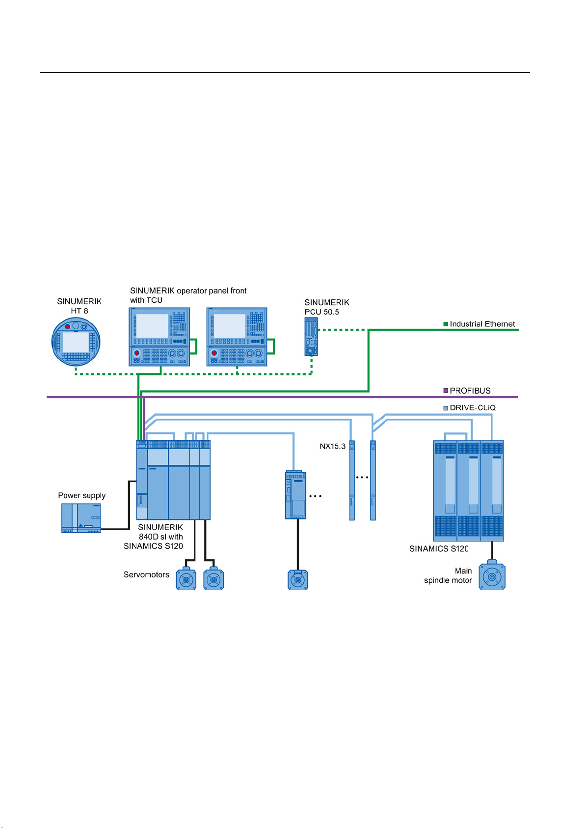
The heart of the SINUMERIK 840D sl is the Numerical Control Unit (NCU). It combines NCK,
HMI, PLC, closed-loop control and communication tasks.
For operation, programming, and visualization purposes, the corresponding operating
software is already integrated into the CNC software for the NCU and therefore runs on the
high-performance NCU multi-processor module. For increased operating performance
requirements, the SINUMERIK PCU 50.5 industrial PC can be used.
With the TCU (Thin Client Unit), the operator panel can be installed as much as 100 meters
away. Up to four distributed operator panel fronts can be operated on an NCU or PCU 50.5.
Figure 2-1 Typical topology of the SINUMERIK 840D sl complete system
Guidelines for machine configuration
22 System Manual, MA 01/2013, 6FC5397-6CP10-0BA2
Page 23

System overview
2.2 System configuration
The following components can be connected to the PPU:
● SINUMERIK operator panel front with TCU/PCU 50.5 and machine control
panel/pushbutton panel
● Handheld units
● SIMATIC CE panel
● SIMATIC S7-300 I/O
● Distributed PLC I/O via PROFIBUS DP connection or PROFINET IO
● Programming device
● SINAMICS S120 drive system with feed and main spindle motors, such as
– 1FT/1FK/1FN/1FW6/1FE1/2SP1 synchronous motors
– 1PH/1PM asynchronous motors
The SINUMERIK 840D sl offers integrated PROFINET functionality.
The following are supported:
● PROFINET CBA functionality (CBA = Component Based Automation)
The CBA functionality integrated in the NCU allows users to modularize machinery and
systems: Rapid real-time communication (up to 10 ms) between the controllers means
that systems lend themselves better to standardization and can be reused or expanded
more easily. Response to customer demands is faster and more flexible and startup is
simplified and speeded up by pretesting at component level.
● PROFINET IO
As part of PROFINET, PROFINET IO is a communication concept that is used to
implement modular, distributed applications. PROFINET IO is based on Industrial
Ethernet and allows distributed field and I/O equipment to be connected to the central
processing unit.
128 PROFINET IO devices can be operated on the NCU as an IO controller.
Guidelines for machine configuration
System Manual, MA 01/2013, 6FC5397-6CP10-0BA2
23
Page 24

System overview
2.3
Variants
Application areas and performance
Note
Connection of SINAMICS S120 Combi
An NCU 710.3 PN is required in order to use a SINAMICS S120 Combi drive system.
This version is not discussed in this document.
Further information
2.3 Variants
Thanks to the scalability of the hardware and software, both in the controller and operating
areas, the SINUMERIK 840D sl can be used in many sectors. The possibilities range from
simple positioning tasks up to complex multi-axis systems.
● Up to eight axes can be implemented on an NCU 710.3 PN in SERVO control mode, with
a sampling time of 125 µs for both the speed and current controllers. In order to achieve
this maximum number of axes, the NCU 710.3 PN must be extended by up to two NX
modules.
● On the NCU 720.3 PN/730.3 PN, the number of axes can be increased to as many as 31
● Using the Option Board CBE30-2, three NCU 7x0.3 PN can be linked to each other by
● The NCU 730.3 PN is recommended for maximum dynamics and accuracy in mold
Please refer to the following for detailed information on the number of axes and controller
axis performance:
/FH1/ SINAMICS S120 Function Manual Drive Functions, 01/2012 edition, Chapter 12.12.
and/or the drive control performance can be improved in SERVO control mode, with a
sampling time of 125 µs for both the speed and current controllers. This is achieved by
using the NX10.3/NX15.3 module. The NCU 720.3 PN/730.3 PN can be extended by up
to five NX10.3/NX15.3 modules for the purposes of drive control performance and
number of axes.
means of the NCU link functionality, so that 93 axes in total can be controlled by an NCU.
making applications or the high-speed cutting sector. Since it has the highest PLC
capacity, it represents the most advanced configuration within the SINUMERIK 840D sl
range.
Guidelines for machine configuration
24 System Manual, MA 01/2013, 6FC5397-6CP10-0BA2
Page 25

System overview
2.4
SINAMICS S120 / SINUMERIK 840D sl Component Overview
Introduction
2.4 SINAMICS S120 / SINUMERIK 840D sl Component Overview
Coordinated drives that carry out a drive and motion task together are used in many
mechanical and plant engineering applications. These require drives with a coupled DC link,
which allows for cost-saving energy compensation between braking and driving axes.
SINAMICS S120 features Line Modules (infeed modules) and Motor Modules (inverter
modules) covering a wide performance range which, having been designed in booksize
format for seamless installation, pave the way for compact multi-axis drive configurations.
The SINAMICS S120 control module, the CU320-2 Control Unit, is able to handle simple
technological tasks by itself. For challenging numerical tasks, it is replaced by or extended to
include powerful modules from the SINUMERIK 840D sl product range.
The SINUMERIK NCU 7x0.3 PN Numerical Control Units can be positioned in or next to the
SINAMICS S120 drive line-up and connected via DRIVE-CLiQ.
In the case of tasks that require a greater number of motion axes due to the machine
kinematics, the system base units can be expanded with the additional NX10.3/NX15.3
Control Units.
Guidelines for machine configuration
System Manual, MA 01/2013, 6FC5397-6CP10-0BA2
25
Page 26
System overview
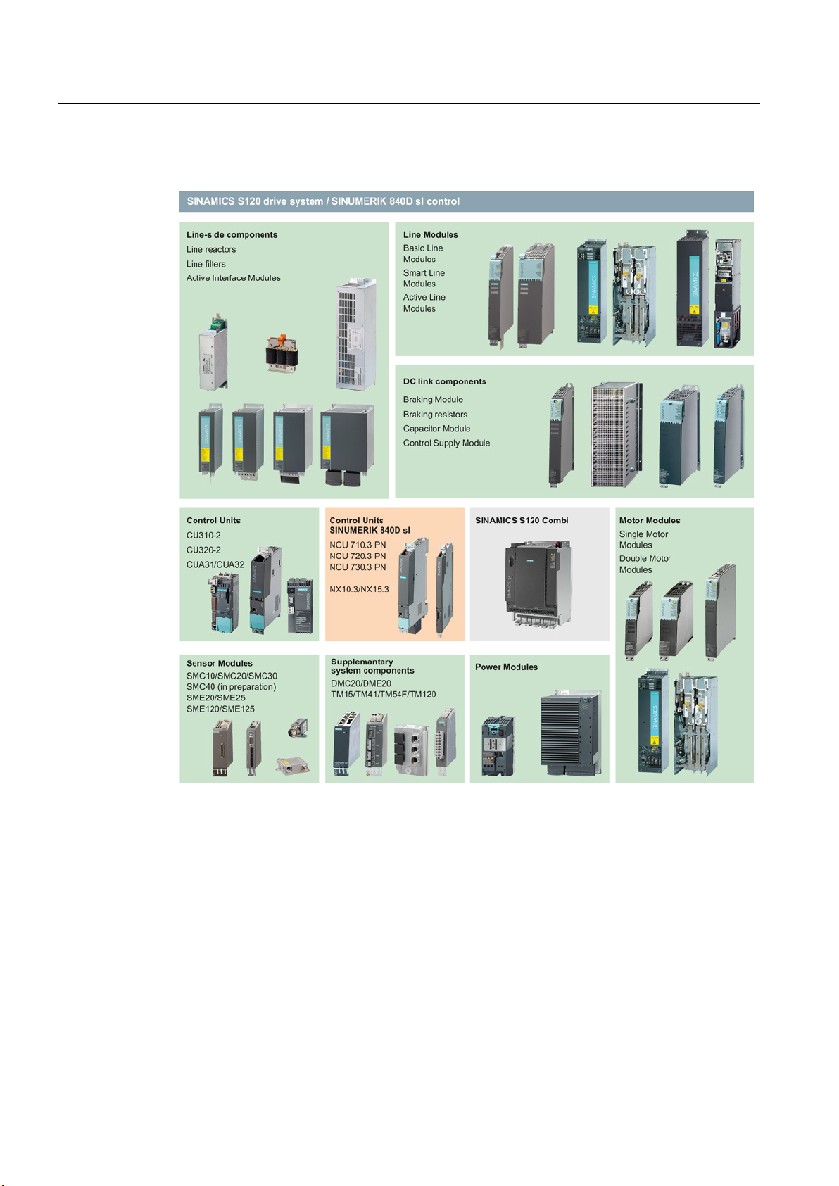
Components of the SINAMICS S120 drive system and SINUMERIK 840D sl control
2.4 SINAMICS S120 / SINUMERIK 840D sl Component Overview
Figure 2-2 SINAMICS and SINUMERIK components
Guidelines for machine configuration
26 System Manual, MA 01/2013, 6FC5397-6CP10-0BA2
Page 27

System overview
Function of components
Overview
Product family
Component group
Component/function
Types
CLiQ interfaces)
2.4 SINAMICS S120 / SINUMERIK 840D sl Component Overview
● Line-side power components such as fuses, contactors, reactors, and filters are used for
switching the energy supply and meeting EMC requirements.
● Line Modules generate DC voltage from the three-phase line voltage, and transfer the
central energy supply to the DC link and, if necessary, the regenerative feedback to the
network.
– Basic Line Modules (BLM) generate a non-stabilized DC link voltage and are not
capable of regenerative feedback. They are not generally used for multi-axis drive
configurations.
– Smart Line Modules generate a non-stabilized DC link voltage and are capable of
regenerative feedback.
– Active Line Modules generate a stabilized DC link voltage and are capable of
regenerative feedback.
● DC link components such as Braking Modules and Capacitor Modules are used as an
option for the purpose of stabilizing the DC link voltage.
● Motor Modules work as inverters. They draw their power from the DC link and supply the
connected motors.
● Additional system components expand the range of functions and cover different
interfaces for encoders and process signals.
● The Control Unit processes cross-axis drive and technological functions.
The table below only takes into account those SINAMICS S120 booksize format components
that are supported by SINUMERIK 840D sl.
Table 2- 1 SINAMICS and SINUMERIK components (selection)
SINUMERIK Numerical Control Units Control center
SINUMERIK Numeric Control Extensions Expansion modules for the NCU
(computing power and DRIVE-
SINUMERIK Operating unit Industrial PC
SINUMERIK Operating unit Thin Client Unit
SINUMERIK Operator panels Operator panels with display and
keyboard that can be connected
as distributed components
• NCU 710.3 PN
• NCU 720.3 PN
• NCU 730.3 PN
• NX10.3
• NX15.3
• PCU 50.5
• TCU
• OP 08T
• OP 010/OP 010S/OP 010C
• OP 012
• OP 015/OP 015A/OP 015AT
• TP 015A/TP 015AT
• OP 019
Guidelines for machine configuration
System Manual, MA 01/2013, 6FC5397-6CP10-0BA2
27
Page 28

System overview
Product family
Component group
Component/function
Types
Ethernet (CBE)
2.4 SINAMICS S120 / SINUMERIK 840D sl Component Overview
SINUMERIK Communication Board
SINAMICS
S120 Booksize
SINAMICS
S120 Booksize
SINAMICS
S120 Booksize
SINAMICS
S120 Booksize
SINAMICS
S120 Booksize
SINAMICS
S120 Booksize
SINAMICS
S120 Booksize
Line-side components Active Interface Module
Line-side components High frequency line reactor with a
Line-side components Line reactor for SLM
Line-side components Basic Line Filter for ALM
Line-side components Wideband Line Filter for ALM
Line-side components Line filters for SLM
Line Modules Active Line Module (ALM)
CBE for NCU link
damping resistor (HFD reactor) for
ALM
• CBE30-2
• 16 kW
• 36 kW
• 55 kW
• 80 kW
• 120 kW
• 16 kW
• 36 kW
• 55 kW
• 80 kW
• 120 kW
• 5 kW
• 10 kW
• 16 kW
• 36 kW
• 55 kW
• 16 kW
• 36 kW
• 55 kW
• 16 kW
• 36 kW
• 55 kW
• 80 kW
• 120 kW
• 5 kW
• 10 kW
• 16 kW
• 36 kW
• 55 kW
• 16 kW
• 36 kW
• 55 kW
• 80 (64) kW
• 120 (84) kW
Guidelines for machine configuration
28 System Manual, MA 01/2013, 6FC5397-6CP10-0BA2
Page 29

System overview
Product family
Component group
Component/function
Types
S120 Booksize
with safe electrical separation
2.4 SINAMICS S120 / SINUMERIK 840D sl Component Overview
SINAMICS
S120 Booksize
SINAMICS
SINAMICS DC link components Braking resistors
SINAMICS DC link components Capacitor Module
SINAMICS DC link components Control Supply Module (CSM)
SINAMICS Control units Control Unit for more
SINAMICS Motor Modules Single Motor Module (SMM)
SINAMICS Motor Modules Double Motor Module (DMM)
SINAMICS Sensor Modules Sensor Modules Cabinet
SINAMICS Sensor Modules Sensor Modules External
SINAMICS DRIVE-CLiQ hubs DRIVE-CLiQ hub Cabinet
SINAMICS DRIVE-CLiQ hubs External DRIVE-CLiQ hub
SINAMICS Terminal Modules Terminal expansion
SINAMICS Terminal Modules Emulating an incremental encoder
SINAMICS Terminal Modules Temperature sensor evaluation
Line Modules Smart Line Module (SLM)
DC link components Braking Module (BM)
straightforward functions
• 5 kW
• 10 kW
• 16 kW
• 36 kW
• 55 kW
• 1.5 kW/100 kW
• 0.3 kW/25 kW
• 1.5 kW/100 kW
• 5 kW/30 kW
• 12.5 kW/75 kW
• 4000 μF
• 3 AC 380 ... 480 V
• CU320-2 PN
• CU320-2 DP
• 3 A/5 A/9 A/18 A/30 A/45 A/60
A/85 A/132 A/200 A
• 2x3 A/2x5 A/2x9 A/2x18 A
• SMC10/SMC20/SMC30
SMC40 (in development)
• SME20/SME25
• SME120/SME125
• DMC20
• DME20
• TM15
• TM41
• TM120
SINAMICS Voltage Protection Module DC link voltage limit
SINAMICS Additional system component Control Unit Adapter
Guidelines for machine configuration
System Manual, MA 01/2013, 6FC5397-6CP10-0BA2
• VPM120
• VPM200
• VPM200 Dynamic
• CUA31
29
Page 30
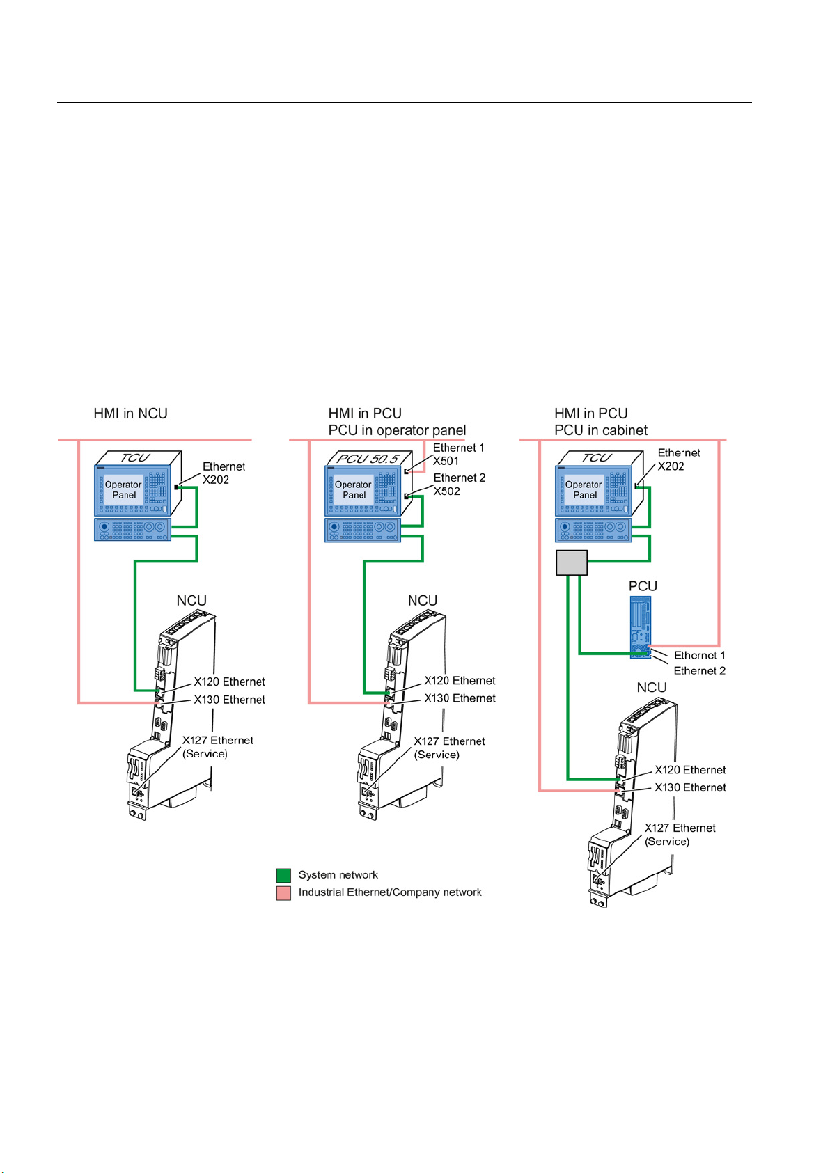
System overview
2.5
User interface software (HMI software)
Connection of the NCU 7x0.3 to the HMI software
2.5 User interface software (HMI software)
The HMI software is used to operate and program machine tools. It is available in several
versions as user interface software integrated into the CNC software:
● SINUMERIK Operate
● SINUMERIK Integrate
A Thin Client Unit (TCU) or, if higher operating performance is required, an industrial PC
PCU 50.5, is responsible for communication between the NCU and the operator panel front.
Figure 2-3 HMI software connection options
Guidelines for machine configuration
30 System Manual, MA 01/2013, 6FC5397-6CP10-0BA2
Page 31

System overview
Switching between operator panels
Note
Detailed information about the operator panels, TCU and PCU
Operator Components Equipment Manual" and in "CNC Commissioning, Part 2 (HMI)".
2.5 User interface software (HMI software)
When an Ethernet switch is used, you can switch between embedded HMI (available on
NCU) and HMI-Advanced (available on PCU 50.5).
Figure 2-4 HMI connection with switch
50.5 is contained in the "sl
Guidelines for machine configuration
System Manual, MA 01/2013, 6FC5397-6CP10-0BA2
31
Page 32

System overview
2.6
Function of installation altitude and ambient temperature
level in [m]
Air pressure in mbar [kPa]
100
90
80
70
62
54
SINUMERIK 840D sl components
SINAMICS S120 power units
2.6 Function of installation altitude and ambient temperature
Table 2- 2 Air pressure for various installation altitudes
The air pressure and therefore air density drop at altitudes above sea level. The same
quantity of air does not have the same cooling effect and the air clearance between two
electrical conductors can only insulate a lower voltage. Typical values for air pressure are
summarized in the table below:
Installation altitude above sea
0 1000 2000 3000 4000 5000
The components of the SINUMERIK 840D sl system are intended for a weatherproof, fixed
location. The rated conditions exceed requirements according to EN 61131-2.
SINUMERIK components are designed for operation at ambient temperatures of 0° to 55 °C
and at installation altitudes of up to 1000 m above sea level. At altitudes of 1000 m and
higher, the max. ambient temperature decreases by 3 °C with every 1000 m increase in
altitude.
The Line Modules and Motor Modules are designed for operation at an ambient temperature
of 40 °C, installation altitudes up to 1000 m above sea level and the relevant specified pulse
frequency.
The output current must be reduced if the modules are operated at ambient temperatures
above 40 °C (see derating characteristics for the individual modules). Ambient temperatures
above 55 °C are not permissible.
The air gaps inside the devices can insulate surge voltages of surge voltage category III in
accordance with EN 60664-1 up to an installation altitude of 2000 m. At installation altitudes
above 2000 m, the Line Modules must be connected via an isolating transformer. The
isolating transformer reduces surge voltages of surge voltage category III in power supplies
to surge voltages of surge category II at the power terminals of the Line Modules and
thereby conforms to the permissible voltage values for air gaps inside the unit. The design of
the secondary line system must be as follows:
Guidelines for machine configuration
32 System Manual, MA 01/2013, 6FC5397-6CP10-0BA2
● TN system with grounded neutral point (no grounded line conductor)
● IT system
A reduction of the line supply voltage phase-phase is not necessary.
Page 33

3
3.1
Control Unit NCU 7x0.3 PN
3.1.1
Description
NCU 710.3 PN
NCU 720.3 PN
NCU 730.3 PN
CNC user memory
3 MB (max. 9 MB)
3 MB (max. 15 MB)
3 MB (max. 15 MB)
Max. power consumption
281 W
374 W
374 W
Power loss
21 W
46 W
46 W
DRIVE-CLiQ interfaces
4 6 6
Supported axes
8
31
31
necessary
necessary
The modular concept behind the SINUMERIK 840D sl CNC is suitable for decentralized and
flexible system structures. A Numerical Control Unit (NCU) serves as the control center. It is
available in three configuration levels, which have largely identical structures.
Table 3- 1 Differences between the NCU configuration levels:
Heat dissipation Open-circuit
ventilation; double
fan connected if
Open-circuit
ventilation; double
fan connected if
Cooling fins;
double fan connected
if necessary
Guidelines for machine configuration
System Manual, MA 01/2013, 6FC5397-6CP10-0BA2
33
Page 34

SINUMERIK 840D sl
3.1.2
Interface description
Overview
3.1 Control Unit NCU 7x0.3 PN
The following diagram shows an NCU 730.3 PN with its interfaces and control and display
elements (fault displays and status indicators):
Figure 3-1 NCU 730.3 PN interfaces
Guidelines for machine configuration
34 System Manual, MA 01/2013, 6FC5397-6CP10-0BA2
Page 35

SINUMERIK 840D sl
3.1.3
Interfaces and their terminal assignments
3.1.3.1
DRIVE-CLiQ interfaces X100-X105 (X103)
Properties
Use
Component
Description
NX10/15
Drive expansion module for three to six axes.
Active/Smart/Basic
Line Module
Single/Double Motor Module
connected motors.
SMC10/20/30
(SMC40 in development)
are required in addition to the motor encoder.
SME20/25
SME120/125
the Sensor Module External.
DMC20/DME20
distribution of a DRIVE-CLiQ line.
TM15
system can be expanded with the TM15 Terminal Module.
TM41
Module.
3.1 Control Unit NCU 7x0.3 PN
The information below contains detailed descriptions of those interface terminal assignments
which are used to connect components of the SINAMICS drive line-up.
You can find information on the other interfaces in the "SINUMERIK 840D sl, NCU 7x0.3 PN"
Equipment Manual.
The NCU 7x0.3 PN and its NX1x.3 expansion units are connected to SINAMICS S120
components using the common serial interface DRIVE-CLiQ. Device data (electronic rating
plate) is also transmitted via these lines; this enables the correct data to be configured in a
straightforward way. The standardized cables and connectors reduce the variety of different
parts and cut storage costs.
The following components can be connected via the DRIVE-CLiQ interfaces of the NCU
7x0.3 PN:
Table 3- 2 Components with DRIVE-CLiQ connection
Line Modules provide the central energy supply to the DC link.
Motor Modules draw their power from the DC link to supply the
DRIVE-CLiQ Hub Modules are used to implement star-shaped
The number of available digital inputs and outputs within a drive
An incremental encoder can be emulated using the TM41 Terminal
Guidelines for machine configuration
System Manual, MA 01/2013, 6FC5397-6CP10-0BA2
Sensor Modules Cabinet-Mounted are needed when a motor with a
DRIVE-CLiQ interface is not available and when external encoders
Measuring systems outside the cabinet can be connected directly to
35
Page 36
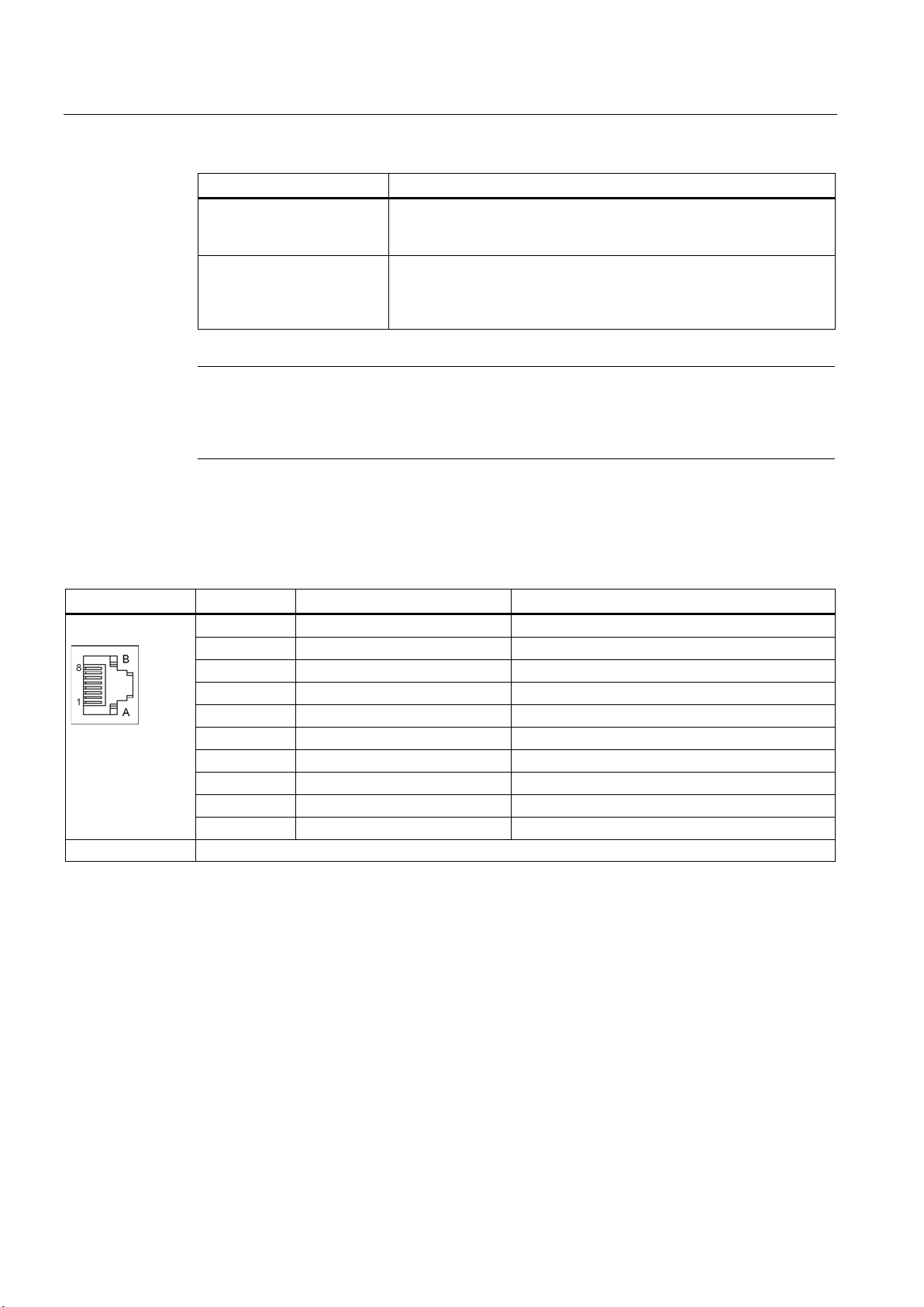
SINUMERIK 840D sl
Component
Description
TM120
well as motors from third-party manufacturers.
CUA31
7x0.3 PN as well.
Note
Although the TM31, TM54F, and TM150 Terminal Modules and the CUA32 Control Unit
Adapter are DRIVE
for this reason are not addressed in this documentation.
Terminal assignment
Pin
Signal name
Technical data
1
TXP
Transmit data +
3
RXP
Receive data +
5
Reserved, do not use
6 RXN
Receive data -
7
Reserved, do not use
8
Reserved, do not use
A
+ (24 V)
Power supply
B
M (0 V)
Electronics ground
Connector type
RJ45 jack
The blanking covers for the DRIVE
Blanking covers (50 pieces) Order number: 6SL3066-4CA00-0AA0
3.1 Control Unit NCU 7x0.3 PN
The TM120 Terminal Module is used for temperature evaluation with
protective separation. It can be used for 1FN and 1FW6 motors as
The CUA31 Control Unit Adapter converts the PM-IF interface to a
DRIVE-CLiQ interface. The CUA31 Control Unit Adapter makes it
possible to operate Power Modules in blocksize format on an NCU
-CLiQ components, they are not supported by SINUMERIK 840D sl and
Table 3- 3 DRIVE-CLiQ interfaces X100-X105 (with NCU 710.3 PN only X100-X103)
2 TXN Transmit data -
4 Reserved, do not use
-CLiQ interfaces are included in the scope of delivery.
For additional specifications for the DRIVE-CLiQ interface and various DRIVE-CLiQ
topologies, see the chapter titled DRIVE-CLiQ topologies (Page 99).
Guidelines for machine configuration
36 System Manual, MA 01/2013, 6FC5397-6CP10-0BA2
Page 37

SINUMERIK 840D sl
3.1.3.2
Digital inputs/outputs X122, X132 and X142
X122 terminal assignment (NCU 7x0.3 PN) using the drive wizard
Pin
no.
Function
Assignment recommendation
BICO source/sink
Line Module with DRIVE-CLiQ connection
Line Module without DRIVE-CLiQ connection
2. OFF3, p0849
(STO enable = p9601)
(STO enable = p9601)
5
Input
No system default
6
Input
No system default
7
Ground for pins 1 to 6
first drive in the group
first drive in the group
11
Ground for pins 9, 10, 12, 13
12
Input
BERO 1 – external zero mark
CU: r0722.10
p0495 = 2
0)
p0488[1...3] = 0
14
Ground for pins 9, 10, 12, 13
3.1 Control Unit NCU 7x0.3 PN
The NCU 7x0.3 PN has three terminal strips, each with 14 terminals. These are used to
control a total of 16 digital inputs, 4 digital outputs, and 8 digital input/outputs. The DIs/DOs
of terminal strips X122 and X132 are used for connecting SINAMICS drives, while the
DIs/DOs of X142 are used for controller connection purposes. When an NCU 7x0.3 PN is
commissioned using the integrated drive wizard in the SINUMERIK Operate HMI software, a
number of terminals are preassigned concrete functions.
1 Input1) ON/OFF 1 infeed for:
Alternative assignment:
"Infeed ready signal" for:
2 Input "OFF3 – rapid stop" CU: r0722.1 Each drive
3 Input SH/SBC 1 - Group 1
SINAMICS Safety Integrated
CU: r0722.0 Line Module: p0840
SLM X21.1
CU: r0722.2 p9620 (all drives in the
Each drive p0864
group)
4 Input SH/SBC 1 - Group 2
SINAMICS Safety Integrated
8 Ground for pins 9, 10, 12, 13
9 Output SH/SBC 1 - Group 1
SINAMICS Safety Integrated
10 Output SH/SBC 1 - Group 2
SINAMICS Safety Integrated
13 Input Probe 1 - central measuring (check that MD13210 =
1)
positive edge required!
CU: r0722.3 p9620 (all drives in the
group)
CU: p0738 p9774 Bit 1
BICO from CU after the
CU: p0739 p9774 Bit 1
BICO from CU after the
CU: p0680[0] = 3 Each drive
Guidelines for machine configuration
System Manual, MA 01/2013, 6FC5397-6CP10-0BA2
37
Page 38

SINUMERIK 840D sl
X132 terminal assignment (for NCU 7x0.3 PN) using the drive wizard
Pin
no.
Function
Assignment recommendation
BICO source/sink
1
Input
No system default
2
Input
No system default
3
Input
No system default
4
Input
Line contactor, feedback signal
CU: r0722.7
Line Module: p0860
5
Input
2. OFF 2
CU: r0722.20
Drive: p0845
6
Input
No system default
7
Ground for pins 1...6
8
Ground for pins 9, 10, 12, 13
connection)
CLiQ connection)
11
Ground for pins 9, 10, 12, 13
Output
Line contactor control
LM : r0863.1
CU: p0744
Input
Bit 15=0
X142 terminal assignment (for NCU 7x0.3 PN) using the drive wizard
Pin no
Function
1
Reserved (not connected)
3
Input
Digital input $A_IN[1]
4
Input
Digital input $A_IN[2]
5
Ground for pins 3, 4, 6, 7, 9, 10, 12, 13
6
Input
Digital input $A_IN[3]
7
Input
Digital input $A_IN[4]
8
Ground for pins 3, 4, 6, 7, 9, 10, 12, 13
9
Output
Digital output $A_OUT[1]
10
Output
Digital output $A_OUT[2]
11
Ground for pins 3, 4, 6, 7, 9, 10, 12, 13
12
Output
Digital output $A_OUT[3]
13
Output
Digital output $A_OUT[4]
14
Ground for pins 3, 4, 6, 7, 9, 10, 12, 13
3.1 Control Unit NCU 7x0.3 PN
9 Output Infeed operation (Line Module with DRIVE-CLiQ
10 Output Infeed ready to start (if Line Module with DRIVE-
12
Otherwise:
13 Input Probe 2 - central measuring (check that
14 Ground for pins 9, 10, 12, 13
BERO 2 – external zero mark CU: r0722.14 Drive: p0495 = 5
MD13210 = 0)
LM : r0863.0 CU: p0742
LM : r0899.0 CU: p0743
CU: p0680[1] = 6
CU: p0728
2 Reserved (not connected)
Each drive
p0489[1...3] = 0
Guidelines for machine configuration
38 System Manual, MA 01/2013, 6FC5397-6CP10-0BA2
Page 39

SINUMERIK 840D sl
DI-DO block diagram of NCU 7x0.3 PN
①
Jumper open: galvanic isolation for digital inputs
②
Assign parameters as digital input/output
3.1 Control Unit NCU 7x0.3 PN
Figure 3-2 Block diagram of X122, X132, and X142 interfaces
Guidelines for machine configuration
System Manual, MA 01/2013, 6FC5397-6CP10-0BA2
39
Page 40

SINUMERIK 840D sl
Note
On terminal strip X142, IN/OUT 0 to IN/OUT 3 are perm
and IN/OUT 4 to IN/OUT 7 as digital outputs, via the software.
3.1.3.3
PROFINET interface X150 P1, P2
Properties
Use
Cable specification
Characteristic
Version
Connector type
RJ45 jack1)
Cable type
Industrial Ethernet cable (CAT5)
Max. cable length
100 m
3.1 Control Unit NCU 7x0.3 PN
anently assigned as digital inputs,
The PROFINET interface X150 is equipped with an integrated 2-port switch and a TCP/IP
address for both ports.
You can install the following communication networks using the PROFINET interface:
● PROFINET CBA (Computer-Based Automation):
● PROFINET IO (input/output devices)
For PROFINET, you always require a data transmission rate of 100 Mbps (Fast Ethernet) in
full duplex mode. For data transfer purposes, you can use twisted-pair copper cables (4-wire,
100Base-T).
Communication between controllers as components in distributed systems
Communication between the PLC controller and field devices
– No support from isochronous mode (PROFINET IRT)
Table 3- 4 Cable specification for X150 ports 1, 2
1)
please use the Fast Connect connector.
Guidelines for machine configuration
40 System Manual, MA 01/2013, 6FC5397-6CP10-0BA2
Page 41

SINUMERIK 840D sl
X150 pin assignment
Pin
Signal name
Signal type
Meaning
1
TXP
B
Transmit data +
2
TXN
B
Transmit data -
3
RXP
B
Receive data +
4 - -
Reserved, do not use
5 - -
Reserved, do not use
6
RXN
B
Receive data -
7 - -
Reserved, do not use
8 - -
Reserved, do not use
Signal type: B = bidirectional
Note
The PROFINET interface has what is known as MDI/MDI
when required, transmit and receive lines are switched over.
necessary.
3.1.3.4
PROFIBUS interface X126
Properties
Note
Isochronous operation with PROFIBUS DP for the NCU is only possible at the line of
term
On the line of terminal X136, only signals from the PLC I/O, and not from SINAMICS drive
units, can be evaluated. Therefore, this terminal will not be taken into account in the
description that follows.
3.1 Control Unit NCU 7x0.3 PN
Table 3- 5 PROFINET interface X150 ports 1, 2
-X autocrossing functionality; i.e.
Thus, no crossover cables are
● Isochronous mode possible
● Isolated RS 485 interface
● Max. data rate 12 MBaud
● Supports master/slave operation
● PROFIBUS address is set via configuration
inal X126.
Guidelines for machine configuration
System Manual, MA 01/2013, 6FC5397-6CP10-0BA2
41
Page 42

SINUMERIK 840D sl
Use
Cable specification
Features
Version
Connector type
9-pin SUB D connector
Cable type
PROFIBUS cable
Max. cable length
100 m at 12 Mbps
X126 pin assignment
Pin
Signal name
Meaning
Area
1 - Reserved, not assigned
ground
3
RxD/TxD-P
Receive/transmit data P (B)
RS485
4
CNTR-P
Control signal
TTL
potential
6
VP
Supply voltage plus
5 V ±10%
proof, 150 mA maximum
8
RxD/TxD-N
Receive/transmit data P (A)
RS485
9 - Reserved, not assigned
3.1 Control Unit NCU 7x0.3 PN
The following devices can be connected to PROFIBUS DP interface X126:
● Distributed I/O
● Drive units with PROFIBUS DP interface (standard slaves)
The PROFIBUS cable is 2-wire, twisted, and shielded with defined technical data.
Table 3- 6 Cable specifications for X126
Table 3- 7 PROFIBUS DP interface X126
Connector type: 9-pin SUB-D connector
The supply voltage VP is provided exclusively for the bus terminal
A teleservice adapter can be connected to the PROFIBUS interface for remote diagnostics
purposes. The power supply for the teleservice (pins 2 and 7) can have a load of up to
150 mA.
2 M24_SERV Power supply for teleservice,
5 DGND PROFIBUS data reference
7 P24_SERV 24 V for teleservice, short-circuit
0 V
24 V (-15% to +20%)
Guidelines for machine configuration
42 System Manual, MA 01/2013, 6FC5397-6CP10-0BA2
Page 43

SINUMERIK 840D sl
NOTICE
Destruction of components if equipotential bonding conductor is missing
PROFIBUS connector
3.1.4
LED displays
Position of the display and operator controls
3.1 Control Unit NCU 7x0.3 PN
If an equipotential bonding conductor is not used, high leakage currents that could destroy
the Control Unit or other PROFIBUS nodes can be conducted via the PROFIBUS cable.
• An equipotential bonding conductor with a cross-section of at least 25 mm² must be
used between components in a system that are located at a distance from each other.
For the first and last nodes in a bus line, the terminating resistors must be switched-in.
Otherwise, data transmission will not function correctly.
The bus terminating resistors are activated in the connector.
The cable shield must be connected at both ends through a large surface area.
Figure 3-3 NCU7x0.3 PN display and operator controls
Guidelines for machine configuration
System Manual, MA 01/2013, 6FC5397-6CP10-0BA2
43
Page 44

SINUMERIK 840D sl
Meaning of LED states
Name
Function
Status
Meaning
monitoring etc. ) or the Control Unit is booting up.
(0.5 Hz)
Orange
Accessing CompactFlash Card
components
POWER ON for the components in question.
Green
NC powered up and everything in cyclic mode
red/orange (1 Hz)
component is activated: (p0124[0] = 1).
RUN
PLC RUN
Green
PLC (programmable logic controller) ready for operation
STOP
PLC STOP
Orange
PLC stopped
SU/PF
PLC FORCE
Red
FORCE activated
SF
PLC SF
Red
PLC group error
DP
BUS1 F
Red
PROFIBUS group error X126
DP/MPI
BUS2 F
Red
PROFIBUS group error X136
PN
PN Fault
Red
PROFINET IO group error X150
OPT
- - No function
Note
PLC memory reset
If all the LEDs are flashing, the PLC (programmable logic controller) must be reset v
mode selector (move switch to position "3" to reboot).
Note
When a connected SINAMICS Control Unit is powering up, all LEDs on the NCU briefly light
up orange. You can carry out a detailed diagnosis using a PG/PC and the operating
software.
3.1 Control Unit NCU 7x0.3 PN
Table 3- 8 Meaning of LED states
RDY Ready Red There is at least one fault (e.g. RESET, watchdog
Flashing red/orange
Flashing orange (0.5 Hz) Updating the firmware of the connected DRIVE-CLiQ
Flashing orange (2 Hz) Firmware update is complete for components. Wait for
Flashing green/orange or
SY/MT MAINT Orange
Error accessing CompactFlash Card
LED-supported recognition of connected DRIVE-CLiQ
• Synchronization status (SY): No function
• Maintenance status (MT) of the NCU:
Maintenance request pending
Guidelines for machine configuration
44 System Manual, MA 01/2013, 6FC5397-6CP10-0BA2
ia the
Page 45

SINUMERIK 840D sl
Meaning of the additional display and operator controls
power-up in order to display status messages.
and force a cold restart.
order to operate the NCU.
this coding switch (0 = standard mode).
Diagnostics button DIAG
Currently has no function
Additional references
3.2
NX1x.3 extension units
3.2.1
Description
Properties
3.2 NX1x.3 extension units
7-segment display Used during commissioning in order to issue test
and diagnostic messages, as well as during
Reset button You can use the reset button to reset the NCU
NCK commissioning switch The NCK switch must be in the "0" position in
PLC mode switch You can select the PLC operating mode using
● You can find a detailed description of LED states during power-up in the "NCU Operating
System (IM7)" section of the Basesoftware and Operating Software Commissioning
Manual.
● For information on drive faults and alarms, see also:
SINAMICS S120/S150 List Manual (LH1)
You can use Numeric Control Extensions (NX1x.3) to enhance the performance of an axis
grouping of the CNC automation system SINUMERIK 840D sl. Each NX10 expands the axis
grouping by up to three additional axes, and each NX15 by up to six.
The NX10/15 has the following interfaces:
● 4 DRIVE-CLiQ (X100 – X103)
● Terminal strip (X122) for six digital inputs and four digital inputs/outputs
● Power supply (X124)
Guidelines for machine configuration
System Manual, MA 01/2013, 6FC5397-6CP10-0BA2
45
Page 46
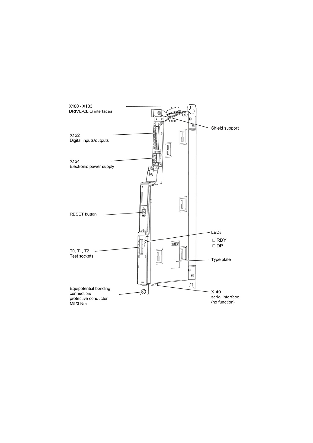
SINUMERIK 840D sl
3.2.2
Representation of the NX1x.3
Interfaces
3.2 NX1x.3 extension units
Figure 3-4 NX15.3 interfaces
Guidelines for machine configuration
46 System Manual, MA 01/2013, 6FC5397-6CP10-0BA2
Page 47

SINUMERIK 840D sl
LED displays
LED
Color
Status
Description
Off
Electronics power supply outside permissible tolerance range
Continuous light
NX10/15 is ready for operation
Flashing 2 Hz
Writing to CompactFlash card of the connected NCU
NX10/15 is booting up.
Flashing 0.5 Hz
Boot error (e.g. firmware cannot be loaded into the RAM)
Continuous light
Firmware loading into RAM
Flashing 0.5 Hz
Unable to load firmware into RAM
Flashing 2 Hz
Firmware CRC fault
NX10/15 is not ready for operation.
running
no cyclic communication is
running
CU_LINK not ready for operation (e.g., after POWER ON)
RESET button
Note
When the button i
without feedback to the control. In other words, the drive and controller run asynchronously
once the drive has successfully booted up.
3.2 NX1x.3 extension units
Table 3- 9 Description of LEDs on the NX10/15
RDY,
READY
H1
Green
Red
Orange
Continuous light At least one fault is pending (e.g., RESET, watchdog monitoring,
basic system fault).
DP1,
CU_LINK
H2
Off Electronics power supply outside the permissible tolerance range,
Green Continuous light CU_LINK is ready for communication and cyclic communication is
Flashing 0.5 Hz CU_LINK is ready for communication and
Red Continuous light At least one CU_LINK fault is present.
The RESET button is on the front of the module under the cover.
s pressed, the locally connected drive systems are brought to a standstill,
Guidelines for machine configuration
System Manual, MA 01/2013, 6FC5397-6CP10-0BA2
47
Page 48

SINUMERIK 840D sl
3.2.3
Interfaces and their terminal assignments
3.2.3.1
X122 digital inputs/outputs
X122 (NX10/15) terminal assignment using the drive wizard
Pin
no.
Function
Assignment recommendation
BICO source/sink
1
Input
No system default
2
Input
No system default
p9601)
p9601)
5
Input
2. OFF 2
NX: r0722.16
Drive: p0845
6
Input
No system default
7
Ground for pins 1 to 6
8
Ground for pins 9, 10, 12, 13
first drive in the group
drive in the group
12
Input
BERO 1 – external zero mark
NX: r0722.10
Drive: p0495 = 2
13
Input
BERO 2 – external zero mark
NX: r0722.11
Drive: p0495 = 3
14
Ground for pins 9, 10, 12, 13
3.2 NX1x.3 extension units
The X122 terminal strip consists of 14 terminals, which are used to control 6 digital inputs
and 4 digital inputs/outputs. When an NX1x is commissioned using the integrated drive
wizard in the SINUMERIK Operate HMI software, a number of terminals are preassigned
concrete functions.
3 Input SH/SBC 1 - Group 1
SINAMICS Safety Integrated (STO enable =
4 Input SH/SBC 1 - Group 2
SINAMICS Safety Integrated (STO enable =
NX: r0722.2 p9620 (all drives in the group)
NX: r0722.3 p9620 (all drives in the group)
9 Output SH/SBC 1 - Group 1
SINAMICS Safety Integrated
10 Output SH/SBC 1 - Group 2
SINAMICS Safety Integrated
11 Ground for pins 9, 10, 12, 13
NX: p0738 r9774 Bit 1
BICO from CU after the
NX: p0739 p9774 Bit 1
BICO from CU after the first
Guidelines for machine configuration
48 System Manual, MA 01/2013, 6FC5397-6CP10-0BA2
Page 49

SINUMERIK 840D sl
DI-DO block diagram of NX1x.3
3.2 NX1x.3 extension units
Figure 3-5 Block diagram of X122 interface
Guidelines for machine configuration
System Manual, MA 01/2013, 6FC5397-6CP10-0BA2
49
Page 50

SINUMERIK 840D sl
3.2.4
NX1x3 wiring
star topology
DRIVE-CLiQ port on the NCU
Drive PROFIBUS addresses
X105
15
X104
14
X103
13
X102
12
X101
11
3.2 NX1x.3 extension units
NX10/15 components can be connected to the control unit via DRIVE-CLiQ. The following
rules apply to wiring of the NX10/15:
● Only one
is permitted between the NX10/15 and the Control Unit, as the
address assignment is fixed (HW configuration). This means that only one NX10/15 can
be operated per DRIVE-CLiQ port on a control unit.
● DRIVE-CLiQ ports not assigned to NX10/15 can be wired to other DRIVE-CLiQ
components
● Once an NX10/15 has been connected and configured, you cannot simply insert it into a
different DRIVE-CLiQ port, as the addresses of the integrated drives are set permanently
from the point of view of the PLC. The following table illustrates this relation:
Table 3- 10 NX10/15 PROFIBUS addresses
The following figure shows a sample topology:
Guidelines for machine configuration
50 System Manual, MA 01/2013, 6FC5397-6CP10-0BA2
Page 51

SINUMERIK 840D sl
Additional references
3.3 Option Board CBE30-2
Figure 3-6 NX10/15 topology
For information on commissioning NX components, please refer to the "IBN CNC: NCK,
PLC, Drive Commissioning Manual".
Guidelines for machine configuration
System Manual, MA 01/2013, 6FC5397-6CP10-0BA2
51
Page 52

SINUMERIK 840D sl
3.3
Option Board CBE30-2
3.3.1
Description
Note
Only one option slot is available on an NCU 7x0.3 PN. T
use a CBE30
Note
Project-specific expansion
For a specific project, an NCU link group with more than three NCUs is available on request
from your regional Siemens contact pe
implemented, more than three NCUs will be rejected with alarm 380020.
Illustration
3.3 Option Board CBE30-2
Using the Communication Board Ethernet CBE30-2, NCU link communication with up to
three NCU 7x0.3 PN Control Units can be configured on the basis of the generally released
standard configuration. In this way, up to 93 axes can be controlled using an NCU. For
CBE30-2, the option slot on the NCU is required.
his means that it is not possible to
-2 and other optional modules in parallel.
rson. Unless project-specific extensions are
Figure 3-7 CBE30-2 Ethernet communication board
Guidelines for machine configuration
52 System Manual, MA 01/2013, 6FC5397-6CP10-0BA2
Page 53

SINUMERIK 840D sl
Link communication
Note
CBE30-2 only for use as link module
The CBE30
general PROFINET communication.
Note
The NCU link communication is exclusively operated using ports 1 and 2
cannot be used and are not freely available.
Note
You can find more detailed information in the SINUMERIK 840D sl NCU 7x0.3 PN
Equipment Manual, as well as in the SINUMERIK 840D sl/828D Extension Functions
Function Manual.
3.3 Option Board CBE30-2
The CBE30-2 is an optional PROFINET module for isochronous real-time communication
(IRT) via Ethernet.
-2 can only be used for NCU link communication. It is not possible to use it for
Figure 3-8 Principle of NCU link communication
The NCU link communication enables cross-NCU data exchange that is synchronous with
the interpolation cycle. Depending on the active functions, cyclic and non-cyclic data
transmissions occur between the NCUs involved in link communication.
. Ports 3 and 4
Guidelines for machine configuration
System Manual, MA 01/2013, 6FC5397-6CP10-0BA2
53
Page 54

SINUMERIK 840D sl
3.3 Option Board CBE30-2
Guidelines for machine configuration
54 System Manual, MA 01/2013, 6FC5397-6CP10-0BA2
Page 55

4
4.1
Structure of the drive line-up
4.1.1
Description
NOTICE
Risk of fire due to excessively long power cables
Note
Arrangement of Motor Modules
Higher
power components then follow. This prevents the DC link busbar of the associated
component becoming overloaded (see the chapter titled
link busbar
Note
Take appropriate measures to fulfill EMC requirements (see the chapters titled
(Page
The individual components, such as the Control Unit and power units, can be attached
directly to each other without any separation. The specified safety and ventilation clearances
above, below, and in front of the associated components must be observed. The maximum
configuration of the drive line-up depends on the rated power of the Line Module or on the
current-carrying capacity of the DC link busbars of the individual components.
The components can be arranged in a single row or multiple rows, or they can be distributed.
In a multiple-row arrangement, vertical installation or, in a cabinet row, side-by-side
installation in different cabinet sections is possible.
Line filters and line reactors are connected between the power supply and the Line Module
in order to stabilize the line infeed and energy recovery. In the case of Active Line Modules,
Active Interface Modules are generally used instead of line filters and reactors.
Excessively long power cables can lead to overheating and a risk of fire, which may result
in the components being destroyed.
• Make sure that the total length of all the power cables does not exceed the values listed
in the chapter titled Maximum cable lengths (Page 474).
-power Motor Modules must be placed directly next to the Line Module. The lower-
Current-carrying capacity of the DC
(Page 161)).
Line filters
125) and Shielding and installing cables (Page 471)).
Guidelines for machine configuration
System Manual, MA 01/2013, 6FC5397-6CP10-0BA2
55
Page 56

SINAMICS drive line-up
Note concerning the use of components with a width of 50 mm
DANGER
Danger to life due to electric shock resulting from incorrectly installed DC link bridges
4.1 Structure of the drive line-up
Incorrectly installed DC link bridges at the left-hand end of the drive line-up can cause an
electric shock.
• Remove the DC link bridges including the screws on a 50 mm-wide Motor Module or DC
link module.
• Do not tighten the screws without the DC link bridges.
• For all components that are 75 mm wide or wider, the DC link bridges must not be
moved to the left or removed.
Figure 4-1 Removal of the DC link bridge
The DC link bridges must be removed by loosening the M4 screws.
Guidelines for machine configuration
56 System Manual, MA 01/2013, 6FC5397-6CP10-0BA2
Page 57

SINAMICS drive line-up
4.1.2
Single row layout
Single row construction with line filter and line reactor
4.1 Structure of the drive line-up
All required components, such as Control Unit and power units are arranged in a row. The
drive line-up is constructed depending on the available space in the control cabinet.
The following rule is used as installation rule of the power units from left to right:
● Line Module
● Motor Modules depending on their power, starting with the highest power and ending with
the lowest power
● DC link components (e.g. Braking Module, Control Supply Module, Capacitor Module)
With Smart Line Modules and Basic Line Modules, line stabilizing technology line filters and
line reactors are used.
Figure 4-2 Single row construction with line filter and line reactor
Guidelines for machine configuration
System Manual, MA 01/2013, 6FC5397-6CP10-0BA2
57
Page 58

SINAMICS drive line-up
Single row construction with Active Interface Module
Note
Lower radio interference voltage through the use of a Basic Line Filter
Installing a Basic Line Filter before the AIM improves the radio interference voltage category
(see also the chapter titled
See also
4.1 Structure of the drive line-up
Active Interface Modules are used exclusively in combination with Active Line Modules.
Figure 4-3 Single row construction with Active Interface Module
Basic Line Filters for Active Line Modules (Page 127)).
Connection of the SINUMERIK components (Page 66)
Guidelines for machine configuration
58 System Manual, MA 01/2013, 6FC5397-6CP10-0BA2
Page 59

SINAMICS drive line-up
4.1.3
Two-row/Multiple-row construction
Note
Observe the installation and ventilation clearances in the chapter titled
cable installation clearance
Two/multi-row construction with line filter and line reactor
4.1 Structure of the drive line-up
The components of the SINAMICS system can also be constructed as two or more rows. As
described above, the limit is the maximum DC link length and the current-carrying capacity of
the DC link busbar.
Note for connection
(Page 78).
Figure 4-4 Two-row construction with line filter and line reactor
Guidelines for machine configuration
System Manual, MA 01/2013, 6FC5397-6CP10-0BA2
59
Page 60
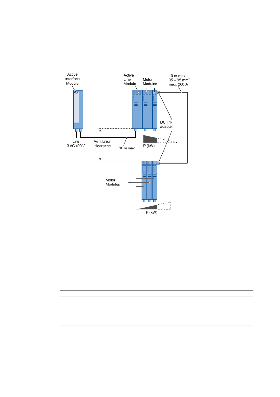
SINAMICS drive line-up
Two/multi-row construction with Active Interface Module
Note
For information on the NCU
components
Note
Lower radio interference voltage through the use of a Basic Line Filter
Installing a Basic Line Filter before the AIM improves the radio interference voltage category
(see also the chapter titled
4.1 Structure of the drive line-up
Active Interface Modules are used exclusively in combination with Active Line Modules.
Figure 4-5 Two-row construction with Active Interface Module
DC link adapters are used to forward the DC link. Cross-sections of 35 mm² to 95 mm², max.
200 A, can be connected to the connection terminals.
The wiring outside the components is based on single-core, finely stranded, shielded cables.
These should be laid in such a way that they are inherently short-circuit and earth fault proof.
The individual wires must be shielded, and the shield must be attached at both ends.
7x0 or NX1x layout, see Connection of the SINUMERIK
(Page 66).
Basic Line Filters for Active Line Modules (Page 127)).
Guidelines for machine configuration
60 System Manual, MA 01/2013, 6FC5397-6CP10-0BA2
Page 61

SINAMICS drive line-up
Minimum size for the ventilation clearances for the two-/multi-row construction
4.1 Structure of the drive line-up
Figure 4-6 Ventilation clearance for the two-row construction
● The distance between the rows of components largely depends on the wiring, the cable
cross-section, and the bending radius of the power cables to be connected.
● The inlet temperature of the air sucked in for cooling the components must not exceed
40 °C (with derating, it must not exceed 55 °C). This must be ensured by means of
suitable air guidance, e.g. involving the distance between the component rows or air
baffle plates.
Guidelines for machine configuration
System Manual, MA 01/2013, 6FC5397-6CP10-0BA2
61
Page 62

SINAMICS drive line-up
4.1.4
Center infeed (single row construction) for 16 to 120 kW Line Modules
Center infeed with line filter and line reactor
Center infeed with Active Interface Module
4.1 Structure of the drive line-up
Another variant of the DC link supply is the center infeed. For the 16 to 120 kW Line
Modules, the DC link can be fed from both the left and right side of the device. This allows
the drive group to be mounted on both sides. The installation guidelines are the same as the
previous guidelines.
Figure 4-7 Construction of center infeed with line filter and line reactor
Active Interface Modules are used exclusively in combination with Active Line Modules.
Figure 4-8 Center infeed installation with Active Interface Module
Guidelines for machine configuration
62 System Manual, MA 01/2013, 6FC5397-6CP10-0BA2
Page 63

SINAMICS drive line-up
Note
Lower radio interference voltage through the use of a Basic Line Filter
Installing a Basic Line Filter before the AIM improves the radio interference voltage category
(see also the cha
Note
For information on the NCU
SINUMERIK components
4.1.5
Distributed configuration
Component width 50/100 mm
Component width 150 ... 300 mm
Safety instructions
WARNING
Ground fault and short-circuit-proof installation
4.1 Structure of the drive line-up
pter titled Basic Line Filters for Active Line Modules (Page 127)).
7x0 or NX1x layout, see the chapter titled Connection of the
(Page 66).
For the distributed installation, an external busbar is used for the DC link connection. From
there, the cables are led to the power units. DC link rectifier adapters are used for the
connection to the power units..
Depending on the component width, two variants are available:
DC link rectifier adapter with connection option from 0.5 mm² to 10 mm²,
max. 36 A.
DC link rectifier adapter with connection option from 35 mm² to 95 mm²,
max. 240 A.
The DC link connection cables must be laid in such a way that they are ground-fault and
short-circuit proof in accordance with DIN/VDE 0100 or suitable fuse protection must be
provided.
The total length of the DC link (including the connection cables) must not exceed 10 m.
Guidelines for machine configuration
System Manual, MA 01/2013, 6FC5397-6CP10-0BA2
63
Page 64

SINAMICS drive line-up
Decentralized structure with line filter and line reactor
Decentralized structure with Active Interface Module
4.1 Structure of the drive line-up
Figure 4-9 Decentralized structure with line filter and line reactor
Active Interface Modules are used exclusively in combination with Active Line Modules.
Figure 4-10 Decentralized structure with Active Interface Module
Guidelines for machine configuration
64 System Manual, MA 01/2013, 6FC5397-6CP10-0BA2
Page 65

SINAMICS drive line-up
Note
Lower radio interference voltage through the use of a Basic Line Filter
Installing a Basic Line Filter before the AIM improves the radio interference voltage category
(see also the chapter titled
Note
Fuses in the power units
The fuses shown in the figures above are optional, as booksize power units already have
internal fuse protection. This also means that it is not essential to use short
cables.
Additional references
4.1 Structure of the drive line-up
Basic Line Filters for Active Line Modules (Page 127)).
-circuit-proof
For details of DC link rectifier adapters in booksize format and how to install them, as well as
information on cable installation, please refer to
/GH2/ SINAMICS S120/ Booksize Power Units Equipment Manual/.
Guidelines for machine configuration
System Manual, MA 01/2013, 6FC5397-6CP10-0BA2
65
Page 66

SINAMICS drive line-up
4.2
Connection of the SINUMERIK components
4.2.1
Layout and fastening of the NCU/NX modules
Fastening the NCU 7x0/NX modules
Fastening Possibilities
NCU 7x0
NX
NCU 7x0+NXs
A (direct to the Line Module)
possible
possible
–
B (with fastening clip)
–
possible
–
C (with spacer)
possible
possible
possible
4.2 Connection of the SINUMERIK components
For the fastening of the NCU / NX modules, a differentiation is made between fastening
using direct installation, using fastening clip or using spacers.
The fastening of the NX component to the NCU differs depending on whether an NCU 710 or
an NCU 720/730 is used (cooling fins on the rear side of the NCU 720/730).
Guidelines for machine configuration
66 System Manual, MA 01/2013, 6FC5397-6CP10-0BA2
Figure 4-11 Main NCU-NX mounting types
Table 4- 1 Fastening possibilities for NCU 7x0 and NX
Page 67

SINAMICS drive line-up
Note
To ensure the optimum reachability and the access to the connection plugs for digital signals
/ bus connections, the following placement notes should
4.2.2
Layout of the NX for single row construction integrated in the power unit group
4.2 Connection of the SINUMERIK components
be observed.
If NX components are present, they should be added between the power unit and the NCU.
This ensures the best-possible reachability and access to the connection plugs for digital
signals / bus connections.
Figure 4-12 NX between NCU and Line Module
Guidelines for machine configuration
System Manual, MA 01/2013, 6FC5397-6CP10-0BA2
67
Page 68

SINAMICS drive line-up
4.2.3
NCU/NX layout as offset solution
4.2.4
Direct installation of a CU-/NCU-/NX module on the Line Module
Remove the holder for securing the Control Unit.
(e.g. two 0.8 x 4.0 screwdrivers)
4.2 Connection of the SINUMERIK components
The DRIVE-CLiQ connection of the SINAMICS components permits any layout of the NCU /
NX modules. The layout of the NCU / NX directly in the drive group is thus not mandatory.
This type of installation involves fastening clips or spacers. To stabilize a group containing
several NX components, specially prepared connection brackets can be fastened to the front
of the NX between the components.
Figure 4-13 NCU/NX as offset solution
Use suitable tools to lift the interlocking
mechanism and push up the holder
The Line Modules permit the docking of a CU320-/NCU-/NX component using the fastening
elements present as standard on the left-hand side of the housing.
If an additional component is to be flush-mounted to the left of the component, the holders
for securing the Control Unit must be removed.
Remove the holder After the removing the holder
Guidelines for machine configuration
68 System Manual, MA 01/2013, 6FC5397-6CP10-0BA2
Page 69

SINAMICS drive line-up
4.3
Shield Connection
4.3.1
SINAMICS Components Dimension Drawings (Internal Air Cooling)
4.3 Shield Connection
For information on the shield connection, please see the dimension drawings of the
SINAMICS components.
For details of the shield connections of Active Interface Modules, refer to the relevant figures
in the Overview chapter. The shield connections are located near the line supply
connections.
Figure 4-14 Dimension drawing of shield connecting plate on a 100 mm component with internal air
cooling, all dimensions in mm and (inches)
Guidelines for machine configuration
System Manual, MA 01/2013, 6FC5397-6CP10-0BA2
69
Page 70

SINAMICS drive line-up
4.3 Shield Connection
Figure 4-15 Dimension drawing of shield connecting plate on a 150 mm component with internal air
cooling, all dimensions in mm and (inches)
Guidelines for machine configuration
70 System Manual, MA 01/2013, 6FC5397-6CP10-0BA2
Page 71

SINAMICS drive line-up
4.3 Shield Connection
Figure 4-16 Dimension drawing of shield connecting plate on a 200 mm component with internal air
cooling, all dimensions in mm and (inches)
Guidelines for machine configuration
System Manual, MA 01/2013, 6FC5397-6CP10-0BA2
71
Page 72

SINAMICS drive line-up
4.3 Shield Connection
Figure 4-17 Dimension drawing of shield connecting plate on a 300 mm component with internal air
cooling, all dimensions in mm and (inches)
Guidelines for machine configuration
72 System Manual, MA 01/2013, 6FC5397-6CP10-0BA2
Page 73

SINAMICS drive line-up
4.3.2
SINAMICS Components Dimension Drawings (External Air Cooling)
4.3 Shield Connection
Figure 4-18 Dimension drawing of shield connecting plate on a 100 mm component with external air
cooling, all dimensions in mm and (inches)
Guidelines for machine configuration
System Manual, MA 01/2013, 6FC5397-6CP10-0BA2
73
Page 74

SINAMICS drive line-up
4.3 Shield Connection
Figure 4-19 Dimension drawing of shield connecting plate on a 150 mm component with external air
cooling, all dimensions in mm and (inches)
Guidelines for machine configuration
74 System Manual, MA 01/2013, 6FC5397-6CP10-0BA2
Page 75

SINAMICS drive line-up
4.3 Shield Connection
Figure 4-20 Dimension drawing of shield connecting plate on a 200 mm component with external air
cooling, all dimensions in mm and (inches)
Guidelines for machine configuration
System Manual, MA 01/2013, 6FC5397-6CP10-0BA2
75
Page 76

SINAMICS drive line-up
4.3 Shield Connection
Figure 4-21 Dimension drawing of shield connecting plate on a 300 mm component with external air
cooling, all dimensions in mm and (inches)
Guidelines for machine configuration
76 System Manual, MA 01/2013, 6FC5397-6CP10-0BA2
Page 77

SINAMICS drive line-up
4.3.3
Shield Connection for Internal Heat Dissipation
component
4.3 Shield Connection
The two examples for preassembled cables on power components of different width follow:
Preassembled cable on a 100 mm
Preassembled cable on a 200 mm component
Guidelines for machine configuration
System Manual, MA 01/2013, 6FC5397-6CP10-0BA2
77
Page 78

SINAMICS drive line-up
4.4
Note for the installation clearance for the connection cables
4.4.1
General information
DANGER
Risk of electric shock by incorrectly installed DC link bridge
4.4 Note for the installation clearance for the connection cables
The arrangement of the components and equipment takes account of
● Space requirements
● Cable routing
● Bending radii of the connection cables
MOTION-CONNECT cables, refer to catalog PM21 or NC62
● Heat dissipation
● EMC
The components of the drive line-up should preferably be installed on a conductive mounting
surface to ensure low impedance between the component and the mounting surface.
Mounting plates with a galvanized surface are suitable.
Components are usually located centrally in a cabinet. The necessary mounting and
installation clearances above an below the components can, under certain circumstances,
exceed the minimum clearances specified in the product documentation.
The components can be arranged in one or more tiers. In a multiple-tier arrangement,
vertical installation or, in a cabinet row, side-by-side installation in different cabinet sections
is possible.
To determine the cross-section, use the DC link busbar current carrying capacity given in the
relevant technical data.
A ventilation clearance of 100 mm must be maintained around the line reactor (not including
the mounting surface).
Incorrectly installed DC link bridges at the left-hand end of the drive line-up can cause an
electric shock.
• Remove the DC link bridges including the screws on a 50 mm-wide Motor Module or DC
link module.
• Do not tighten the screws without the DC link bridges.
• For all components that are 75 mm wide or wider, the DC link bridges must not be
moved to the left or removed.
Guidelines for machine configuration
78 System Manual, MA 01/2013, 6FC5397-6CP10-0BA2
Page 79
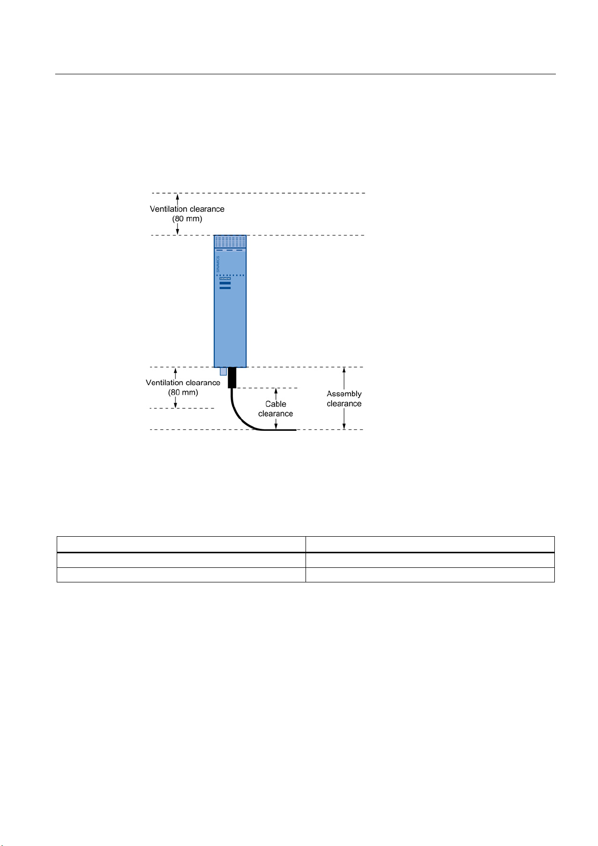
SINAMICS drive line-up
4.4.2
Clearance of the Power Components
4.4.3
Ventilation Clearances of the SINUMERIK Components
Component
Clearance [mm]
NCU 7x0
80 mm
NX1x
80 mm
4.4 Note for the installation clearance for the connection cables
The installation clearance is defined by
● Ventilation clearance
● Cable clearance
Figure 4-22 Clearance in the vicinity of the power components
Table 4- 2 Ventilation clearances above and below the components
Guidelines for machine configuration
System Manual, MA 01/2013, 6FC5397-6CP10-0BA2
79
Page 80

SINAMICS drive line-up
4.5
Heat Dissipation of the Control Cabinet
4.5.1
Control cabinet cooling options
NOTICE
Failure of components due to incorrect installation
4.5 Heat Dissipation of the Control Cabinet
The following options are available for cooling the control cabinet:
● Filter fans
● Heat exchangers
● Cooling units
● Liquid cooling
● External air cooling
● External liquid cooling
The device to be used depends on the associated environmental conditions and the required
cooling capacity.
The air routing within the control cabinet and the cooling clearances specified must be
observed. No components may be installed and no cables routed in the cooling clearance
spaces.
Installing SINAMICS components incorrectly in the cabinet can reduce their service life and
cause them to fail prematurely.
• Observe the guidelines for installing SINAMICS components in the cabinet.
You must take into account the following specifications when installing a SINAMICS drive
line-up:
● Ventilation clearance
● Wiring and cabling
● Air guidance, air-conditioner
Guidelines for machine configuration
80 System Manual, MA 01/2013, 6FC5397-6CP10-0BA2
Page 81

SINAMICS drive line-up
4.5.2
General information on ventilation
Note
For the 5
WARNING
Risk of fire due to overheating as a result of insufficient ventilation clearances
WARNING
Risk of fire due to overheating resulting from covered ventilation slots
WARNING
Risk of fire due to hot spots resulting from a lack of air circulation in sealed cabinets
4.5 Heat Dissipation of the Control Cabinet
SINAMICS components are force-ventilated using integrated fans, and in some cases
through natural convection. The fans are not equipped with temperature-dependent speed
control; only the states "on" or "off" exist.
The fans start when the pulse enable is set, and switch off with a small hysteresis as soon as
the temperature falls below the heat sink temperature saved in the power stack data
(typically 56 °C). The run-on time of the fan depends on various factors such as ambient
temperature, output current, duty cycle and, therefore, cannot be determined directly.
kW and 10 kW Smart Line Modules, the fan runs permanently.
Insufficient ventilation clearances can cause overheating and present a risk for personnel
due to smoke development and fire. This can also result in more failures and reduced
service lives of devices and systems.
• Maintain ventilation clearances of at least 80 mm above and below the components.
• Make sure that warm air can escape at the top.
• If you are using filter fans, heat exchangers, or air conditioners, make sure that the air is
flowing in the right direction.
Covered ventilation slots can cause overheating and present a risk for personnel due to
smoke development and fire. This can also result in more failures and reduced service lives
of devices and systems.
• Route the connected signal and power cables to the components in such a way that
they do not cover the ventilation slots.
If air cannot circulate in the cabinet, this can lead to hot spots that present a risk for
personnel due to smoke development and fire. This can also result in more failures and
reduced service lives of devices and systems.
• Install an internal air circulation system that will ensure the air can flow.
• Install the fan above the components to optimize the air flow (suction).
Air circulation is not required if you are using switchgear with a passive heat dissipation
system.
Guidelines for machine configuration
System Manual, MA 01/2013, 6FC5397-6CP10-0BA2
81
Page 82

SINAMICS drive line-up
Note
The cooling air must flow through the components vertically from bottom (cooler region) to
top (region
The distance between the blow
equipment must be at least 200 mm. With distances that are shorter than this, air baffle
plates must be used in order to divert the air.
①
Cooling unit
②
Control cabinet
4.5 Heat Dissipation of the Control Cabinet
heated by operation).
-out aperture of the air conditioner and the electronic
Figure 4-23 Examples of cabinet ventilation
Guidelines for machine configuration
82 System Manual, MA 01/2013, 6FC5397-6CP10-0BA2
Page 83

SINAMICS drive line-up
NOTICE
Failure of components due to condensation
4.5.3
Cooling clearances
Component
Clearance [mm]
CU320-2
80
Sensor Modules Cabinet-Mounted SMCxx
50
Terminal Modules TMx
50
Active Interface Modules
80
Line reactors for Line Modules
100
80 kW – 120 kW
80 (additional 50 in front of fan)
Smart Line Modules in booksize format
80
Basic Line Modules
80
132 A and 200 A
80 (additional 50 in front of fan)
Braking Module Booksize
80
Control Supply Module
80
Capacitor Module
80
4.5 Heat Dissipation of the Control Cabinet
If air conditioners are used, the relative air humidity of the expelled air increases as the air
in the air conditioner cools and may exceed the dew point. If the relative humidity of the air
entering the SINAMICS components is over 80% for an extended period of time, it can be
assumed that the insulation of the components will fail as a result of electrochemical
reactions.
• Select the air guidance and arrangement of the cooling equipment in such a way that no
condensation can form on the components.
• Use air baffle plates, for example, to ensure that the cold air expelled from the air
conditioner mixes with warm air in the cabinet before it enters the components. This
reduces the relative air humidity to uncritical values.
• Prevent cold air from being blown directly onto electronic equipment.
• If required, install cabinet enclosure heating.
Table 4- 3 Cooling clearances required above and below SINAMICS components
Line filter for Line Modules 100
Active Line Modules
16 kW – 55 kW
Motor Modules Booksize
< 132 A
80
80
Guidelines for machine configuration
System Manual, MA 01/2013, 6FC5397-6CP10-0BA2
83
Page 84

SINAMICS drive line-up
Drive line-up with internal air cooling
4.5 Heat Dissipation of the Control Cabinet
Figure 4-24 Cooling clearances for a drive line-up with internal air cooling (components up to 200
mm width)
Guidelines for machine configuration
84 System Manual, MA 01/2013, 6FC5397-6CP10-0BA2
Page 85

SINAMICS drive line-up
4.5 Heat Dissipation of the Control Cabinet
Figure 4-25 Cooling clearances for 300 mm wide components with internal air cooling with mounted
unit fan
Guidelines for machine configuration
System Manual, MA 01/2013, 6FC5397-6CP10-0BA2
85
Page 86

SINAMICS drive line-up
Drive line-up with external air cooling
4.5 Heat Dissipation of the Control Cabinet
Figure 4-26 Cooling clearances for a drive line-up with external air cooling (components up to 200
mm width)
Guidelines for machine configuration
86 System Manual, MA 01/2013, 6FC5397-6CP10-0BA2
Page 87
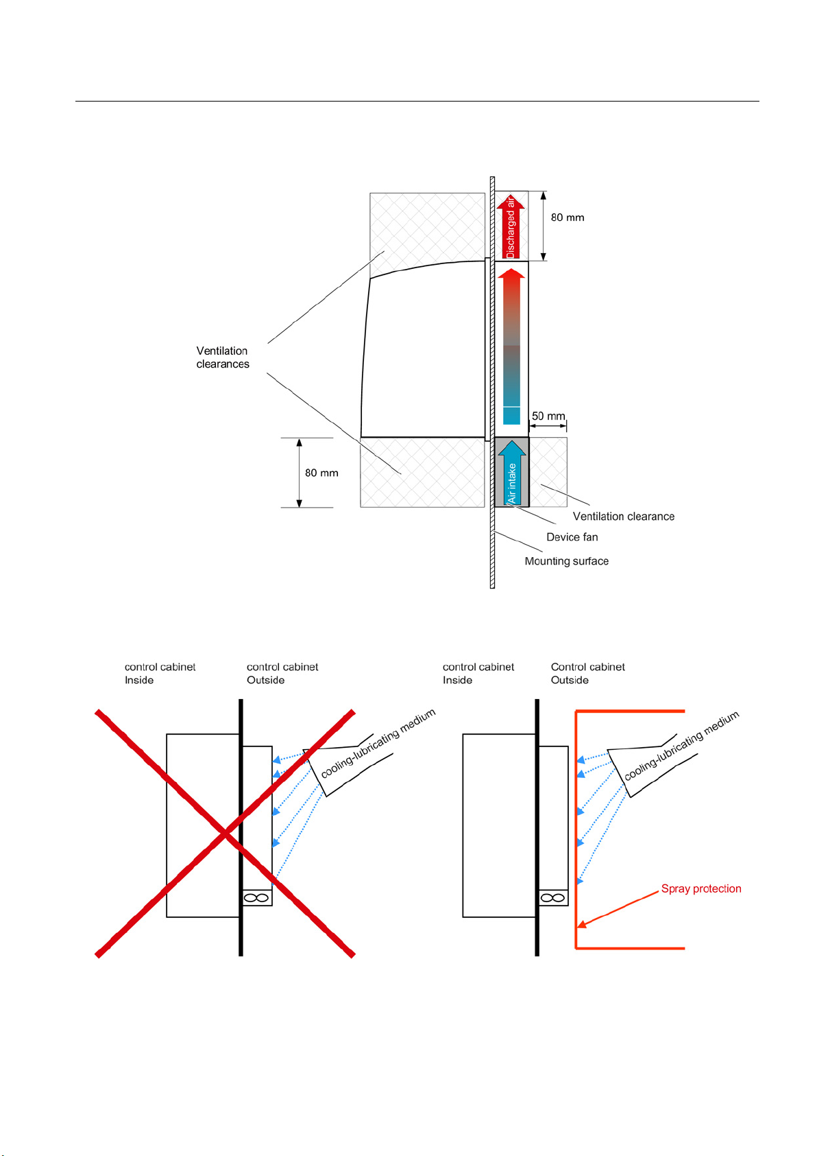
SINAMICS drive line-up
4.5 Heat Dissipation of the Control Cabinet
Figure 4-27 Cooling clearances for 300 mm wide components with external air cooling with mounted
unit fan
Figure 4-28 Spray protection for a drive line-up with external air cooling
Guidelines for machine configuration
System Manual, MA 01/2013, 6FC5397-6CP10-0BA2
87
Page 88

SINAMICS drive line-up
Rail-mounted components
4.5 Heat Dissipation of the Control Cabinet
Figure 4-29 Ventilation clearances for rail-mounted components (e.g. SMC, TM, DMC)
Guidelines for machine configuration
88 System Manual, MA 01/2013, 6FC5397-6CP10-0BA2
Page 89

SINAMICS drive line-up
4.5.4
Dimensioning Climate Control Equipment
Formula to calculate the power loss
Example
Component
Number
Total power loss [W]
(including electronic losses)
Total power loss [W]
CU320-2
1
24
24
kW
Active Interface Module 36 kW
1
340
340
Active Line Module 36 kW
1
666
666
Motor Module 18 A
2
185.4
370.8
Motor Module 30 A
3
309.2
927.6
SMC
5
10
50
SITOP 20
1
53
53
Line contactor
1
12
12
Total:
2469.4
See also
4.5 Heat Dissipation of the Control Cabinet
Cabinet manufacturers provide calculation programs for selecting climate control equipment.
It is important to know the power losses for the components and devices in the control
cabinet.
q = Q - k • A • ΔT
q = thermal power that has to be dissipated through a refrigerator [W]
Q = internal power loss (incl. electronics losses) [W]
∆T = temperature difference between the room and cabinet interior [K]
2
k = heat transfer coefficient, e.g. sheet steel, painted 5.5 [W/(m
2
A = freestanding cabinet surface area [m
]
* K)]
Table 4- 4 Power loss calculation for a drive configuration
Basic Line Filter for AIM/ALM 36
● Assumption:
– freestanding cabinet surface area A = 5 m
– temperature difference between the room and cabinet interior ∆T = 10 K
q = 2469.4 W - 5.5 W/(m
Power Loss of the SINUMERIK Components (Page 516)
Power loss of SINAMICS components (Page 516)
1 26 26
2
2
K) • 5 m2• 10 K = 2194.4 W.
Guidelines for machine configuration
System Manual, MA 01/2013, 6FC5397-6CP10-0BA2
89
Page 90

SINAMICS drive line-up
4.6
Cooling of power units
4.6.1
Internal Air Cooling
4.6 Cooling of power units
With the SINAMICS S120 system, there are four distinct cooling methods for cooling power
units:
● Internal air cooling
● External air cooling
● Cold plate cooling
● Liquid cooling (liquid cooled)
All SINAMICS S120 booksize components are installed within a control cabinet. The total
heat loss of all components is dissipated in the control cabinet. There are three ways to
remove the heat from the control cabinet:
● Filter fans
● Heat exchangers
● Cooling units
The device to be used depends on the associated environmental conditions and the required
cooling capacity. The configuring must also maintain the specified clearances for the
ventilation. No other components may be placed in these areas.
Guidelines for machine configuration
90 System Manual, MA 01/2013, 6FC5397-6CP10-0BA2
Page 91

SINAMICS drive line-up
4.6.2
External Air Cooling
4.6 Cooling of power units
The external air cooling is a cooling system for SINAMICS booksize power units. The
through-hole technology is used for this construction form. The booksize power unit with its
heat sink can be placed in the rectangular cutout of the control cabinet rear wall and installed
with a seal. The heat sink with its cooling fins and fan (contained in scope of delivery)
extends at the back out of the control cabinet and the heat dissipation is made externally
from the control cabinet or in a separate air duct.
Figure 4-30 Installation of a booksize power section with external air cooling
Guidelines for machine configuration
System Manual, MA 01/2013, 6FC5397-6CP10-0BA2
91
Page 92

SINAMICS drive line-up
4.6.3
Cold plate cooling
Special advantages of the cold plate technology
A distinction is made between:
Cold plate with air heat sink
Cold plate with liquid heat sink
Cold plate with internal liquid heat sink
Note
Derating at a temperature of 40 °C and above
In the case of
to the external heat sink. If the temperature at the interface to the power unit is 40 °C,
derating is 20% for 6SL3136
7TE31
When the Active Line Modules and Motor Modules feature direct (internal) liquid cooling
(6SL3135
plate components referred to above.
4.6 Cooling of power units
Cold plate cooling is a cooling system for SINAMICS S120 booksize power units. The flat
aluminum cooling plate located at the rear side of the devices serves as thermal interface.
1. It is particularly suitable for machine concepts in which a high level of dirt accumulates in
the machine vicinity. The reduction of the cabinet-internal heat loss simplifies the heat
dissipation of a sealed control cabinet (IP54).
2. Advantageous for machine concepts for which liquid is already present in the process.
This heat dissipation method is thus suitable for both internal and external cold plate
cooling of the power components.
●
The components of the drive line-up are typically all attached with screws to the cooling
fins of an air heat sink.
●
The components of the drive line-up are typically all attached with screws to the liquid
heat sink.
●
This is considered to be a liquid cooling using a connection adapter. The liquid passes
through the integrated channels in the cold plate.
300 mm-wide modules, derating must be applied due the heat transferred
-2AAx/6SL3126-1TE32-0AAx.
-7TE31-2AA3/6SL3125-1TE32-0AA3), this derating does not apply to the cold
-7TE28-0AAx/6SL3126-1TE31-3AAx and 30% for 6SL3136-
Guidelines for machine configuration
92 System Manual, MA 01/2013, 6FC5397-6CP10-0BA2
Page 93
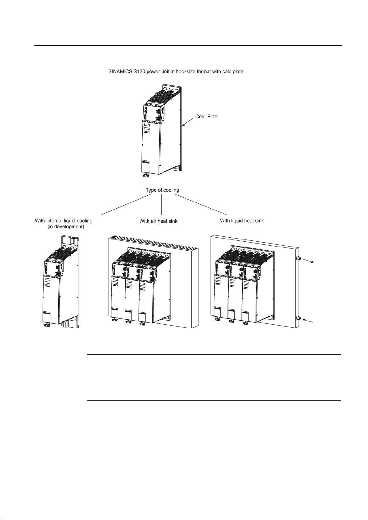
SINAMICS drive line-up
Note
Important for configuration
The associated notes contained in the manuals must be observed for the configuring and the
layout of the corresponding component. This ensures that devices in the control cabinet are
not damaged as a result of leaks, etc.
4.6 Cooling of power units
Figure 4-31 Cooling systems for cold plate
Guidelines for machine configuration
System Manual, MA 01/2013, 6FC5397-6CP10-0BA2
93
Page 94

SINAMICS drive line-up
4.6.4
Liquid cooling (liquid cooled)
Additional references
4.6 Cooling of power units
Liquid cooling is used only for large power units (Active Line Module 120 kW as well as
single Motor Module 200 A).
For liquid cooling, the power semiconductors are mounted on a heat sink, through which the
coolant flows. The power loss of the device is, to large extent, absorbed by the cooling
medium and can be dissipated outside the cabinet.
/GH2/ SINAMICS S120 Booksize Power Modules, chapter "Cooling circuit and coolant
properties".
Guidelines for machine configuration
94 System Manual, MA 01/2013, 6FC5397-6CP10-0BA2
Page 95

5
5.1
Communication overview
The NCU 7x0.3 PN establishes the connection to the operating components and service
units via its Ethernet interfaces. Communication takes place via various networks.
Figure 5-1 Example based on the SINUMERIK 840D sl network configuration
Guidelines for machine configuration
System Manual, MA 01/2013, 6FC5397-6CP10-0BA2
95
Page 96

Communication within the system
Note
The significance of items ①
① (NCU)
② (S7 Hardware Config)
Note
Do not select "TCP/IP (AUTO)…" or "ISO Ind.
Note
As of SW 2.4:
The ports must first be activated where connections via the company network are
involved (X130).
5.1 Communication overview
to ⑤ is explained on the pages that follow.
● IP assignment of the server
● The ports need to be activated if VNC and HMI/Step7 are to be used (SW2.4.xxx and
higher):
/user/system/etc/basesys.ini
[LinuxBase]
FirewallOpenPorts="TCP/102 TCP/5900"
Access parameters need to be set in the S7 hardware configuration.
1. Check the network connection (ping on selected access path X120/X130/X127).
2. Select the PG/PC interface in SIMATIC Manager.
Ethernet ..." under any circumstances!
3. Set parameters for HW Config → Machine control panel using the selected access IP
address (X120/X130/X127).
4. Load the parameter assignment to the station.
Guidelines for machine configuration
96 System Manual, MA 01/2013, 6FC5397-6CP10-0BA2
Page 97

Communication within the system
③ (PG/PC)
On the system network (X120):
On the service network (X127):
④ (System Network Center > TCU support)
5.1 Communication overview
• TCP/IP Internet protocol
– properties
– general
– Set fixed IP addresses
• Example:
– IP: 192.168.214.250
– Sub.: 255.255.255.0
When TCU – PCU50.5 (HMI Advanced) is powered up, the IP address of the PCU must be
entered in the
/user/common/<TCU-Name>/common/tcu/config.ini
file:
[Station]
mcpIndex=…
tcuIndex=…
dckEnable=…
MaxHostIndex=1
[host_1]
Address=192.168.214.241
• TCP/IP Internet protocol
– properties
– general
– IP address obtained automatically
Guidelines for machine configuration
System Manual, MA 01/2013, 6FC5397-6CP10-0BA2
● If the DHCP of the NCU (X120) is active:
Set the "Settings system network" program on the "TCU support" tab.
● Set "No boot support".
97
Page 98

Communication within the system
⑤ (machine control panel – Industrial Ethernet)
Note
The Service menu (Backup/Restore) is only
PCU OP.
mcp_client.ini file
Organization block 100 (OB100):
Note
In B#16#55, the initial "5" refers to the first machine control panel and the last "5" refers to
the second.
5.1 Communication overview
available for an analog monitor, TCU OP, or
●
– copy mcp_client.ini from
/siemens/sinumerik/mcp_client/mcp_client.ini
to
/user/sinumerik/mcp_client/mcp_client.ini
– "addrMode" change: 1=DNS (default) 0=HWS
This may be required after a change of software if the machine control panel no longer
uses PROFIBUS for communication
:
●
CALL "RUN_UP" , "gp_par
"MCPNum :=1
MCP1BusAdr :=192 // bus address in accordance with MCP switch
MCPMPI :=FALSE
MCPSDB210 :=FALSE
MCPCopyDB77 :=FALSE
MCPBusType :=B#16#55 (PROFIBUS = 3)
Guidelines for machine configuration
98 System Manual, MA 01/2013, 6FC5397-6CP10-0BA2
Page 99

Communication within the system
5.2
DRIVE-CLiQ Topologies
5.2.1
DRIVE-CLiQ topology
Introduction
Electronic rating plate
Actual topology
5.2 DRIVE-CLiQ Topologies
DRIVE-CLiQ (Drive Component Link with IQ) is a communication system for connecting the
various SINAMICS components (e.g. Control Unit, Line Module, Motor Modules, motors, and
encoders).
In SINAMICS contexts, the term "topology" refers to the structure of a drive system, including
its DRIVE-CLiQ wiring and other wiring elements.
DRIVE-CLiQ supports the following functions:
● Automatic detection of components by the Control Unit (NCU 7x0.3 or CU320-2)
● Standard interfaces to all components
● Standardized diagnostics down to component level
● Standardized service down to component level
DRIVE-CLiQ components have an electronic type plate in which the characteristic device
data is stored. When connecting the device to the Control Unit, the following information is
transferred via DRIVE-CLiQ:
● Component type (e.g. SMC20)
● Order number (e.g. 6SL3055-0AA0-5BA0)
● Manufacturer (e.g. SIEMENS)
● Hardware version (e.g. A)
● Serial number (e.g. T-PD3005049)
● Technical data (e.g. rated current)
The actual topology is the actual DRIVE-CLiQ cabling tree, which is detected automatically
via DRIVE-CLiQ when the drive system components are started up.
Guidelines for machine configuration
System Manual, MA 01/2013, 6FC5397-6CP10-0BA2
99
Page 100

Communication within the system
Target topology
Comparison of topologies at Power On
5.2 DRIVE-CLiQ Topologies
The target topology is stored on the memory card on the Control Unit and is compared with
the actual topology when the Control Unit is started up.
The target topology can be specified in two ways and saved on the memory card:
● Via the SINUMERIK 840D sl drive wizard or via the STARTER commissioning tool (by
creating the configuration and loading it to the drive unit)
● Via quick commissioning (automatic configuration):
the actual topology is read and the target topology written to the memory card.
Comparing the topologies prevents a component from being controlled/evaluated incorrectly
(e.g. drive 1 and 2).
When the drive system starts up, the Control Unit compares the detected actual topology
and the electronic rating plates with the relevant target topology stored on the memory card.
You can specify how the electronic rating plates are compared for all the components of a
Control Unit via p9906. The type of comparison can be changed subsequently for each
individual component. You can use p9908 for this or right-click in the topology view in the
STARTER tool. All data on the electronic rating plate are compared by default.
The following data in the target and actual topologies is compared depending on the settings
made in p9906/9908:
● p9906/p9908 = 0 component type, order number, hardware version, manufacturer, serial
number
● p9906/p9908 = 1 component type, order number
● p9906/p9908 = 2 component type
● p9906/p9908 = 3 component class (e.g. Sensor Module or Motor Module)
Guidelines for machine configuration
100 System Manual, MA 01/2013, 6FC5397-6CP10-0BA2
 Loading...