

Page 1

User's Guide 11/2002 Edition
Measuring Cycles
SINUMERIK 840D/840Di/810D
Page 2

Page 3

Part 1: User's Guide
SINUMERIK 840D/840Di/810D
Measuring Cycles
User's Guide
Introduction
Description of Parameters
Measuring Cycle Auxiliary
Programs
Measuring in JOG
Measuring Cycles for
Milling and Machining
Centers
1
2
3
4
5
Valid for
Control Software version
SINUMERIK 840D 6
SINUMERIK 840DE (export version) 6
SINUMERIK 840D powerline 6
SINUMERIK 840DE powerline 6
SINUMERIK 840Di 2
SINUMERIK 840DiE (export version) 2
SINUMERIK 810D 3
SINUMERIK 810DE (export version) 3
SINUMERIK 810D powerline 6
SINUMERIK 810DE powerline 6
Measuring Cycles for
Turning Machines
Miscellaneous Functions
Part 2: Description of
Functions
Hardware, Software and
Installation
Supplementary
Conditions
Data Description
Examples
6
7
8
9
10
11
11.02 Edition
Data Fields, Lists
Appendix
12
A
Page 4

Contents 11.02
0
SINUMERIK® Documentation
Printing history
Brief details of this edition and previous editions are listed below.
The status of each edition is shown by the code in the "Remarks" column.
Status code in the "Remarks" column:
A .... New documentation.
B .... Unrevised edition with new Order No.
C .... Revised edition with new status.
If factual changes have been made on the page since the last edition, this is indicated by a
new edition coding in the header on that page.
0
Edition Order No. Remarks
09.95
03.96
6FC5298-3AA01-0BP0
6FC5298-3AA70-0BP1
A
C
12.97 6FC5298-4AA70-0BP0 C
12.98 6FC5298-5AA70-0BP0 C
08.99 6FC5298-5AA70-0BP1 C
06.00 6FC5298-5AA70-0BP2 C
10.00 6FC5298-6AA70-0BP0 C
09.01 6FC5298-6AA70-0BP1 C
11.02 6FC5298-6AA70-0BP2 C
This manual is included in the documentation available on CD ROM (DOCONCD)
Edition Order No. Remarks
11.02 6FC5 298-6CA00-0BG3 C
Trademarks
SIMATIC
POSMO
be trademarks which, if used by third parties, could infringe the rights of their owners.
Further information is available on the Internet under:
http:/www.ad.siemens.de/sinumeri k
This publications was produced with WinW ord V 8.0 and Designer V 7.0.
The reproduction, transmission or use of this document or its contents is not
permitted without express written authority. Offenders will be liable for damages.
All rights, including rights created by patent grant or registration of a utility model
or design, are reserved.
© Siemens AG, 1995–2002. All rights reserved
®
, SIMATIC HMI®, SIMATIC NET®, SIROTEC®, SINUMERIK®, SIMODRIVE® and SIMODRIVE
®
are registered trademarks of Siemens AG. Other product names used in this documentation may
Other functions not described in this documentation might be executable in the
control. This does not, however, represent an obligation to supply such functions
with a new control or when servicing.
We have checked that the contents of this document correspond to the hardware
and software described. Nonetheless, differences might exist and therefore we
cannot guarantee that they are completely identical. The information contained in
this document is, however, reviewed regularly and any necessary changes will be
included in the next edition. We welcome suggestions for improvement.
Subject to change without prior notice
Order No. 6FC5298-6AA70-0BP2
Printed in Germany
Siemens Aktiengesellschaft
Page 5

11.02 Contents
0
Contents
Part 1: User's Guide
Introduction 1-15
0
1.1 Basics.............................................................................................................................. 1-16
1.2 General preconditions ..................................................................................................... 1-17
1.3 Plane definition................................................................................................................ 1-19
1.4 Suitable probes ............................................................................................................... 1-20
1.5 Workpiece probe, calibration tool in TO memory............................................................ 1-22
1.5.1 Workpiece probe in TO memory for milling machines and machining centers ........ 1-22
1.5.2 Workpiece probe, calibration tool in TO memory on turning machines .................... 1-23
1.6 Measuring principle ......................................................................................................... 1-25
1.7 Measuring strategy and compensation value calculation for tools with automatic
tool offset......................................................................................................................... 1-28
1.8 Parameters for checking the dimension deviation and compensation............................ 1-31
1.9 Effect of empirical value, mean value and tolerance parameters ................................... 1-37
1.10 Reference points on the machine and workpiece ........................................................... 1-38
1.11 Measurement variants for milling machines & machining centers .................................. 1-39
1.11.1 Workpiece measurement for milling machines......................................................... 1-39
1.11.2 Measurement variants for fast measurement at a single point ................................. 1-40
1.11.3 Measurement variants for workpiece measurement paraxial ................................... 1-40
1.11.4 Measurement variants for workpiece measurement at random angles .................... 1-42
1.11.5 Measuring a surface at a random angle ................................................................... 1-43
1.12 Measurement variants for lathes.................................................................................... 1-44
1.12.1 Tool measurement for lathes .................................................................................... 1-44
1.12.2 Workpiece measurement for turning machines: Single-point measurement............ 1-45
1.12.3 Workpiece measurement for turning machines: Two-point measurement ............... 1-47
1.13 Measuring cycles interface............................................................................................. 1-48
1.13.1 Displaying measuring result screens ........................................................................ 1-48
1.13.2 Setting parameters.................................................................................................... 1-50
Description of Parameters 2-53
2.1. Parameter concept for measuring cycles........................................................................ 2-54
2.2 Parameter overview ........................................................................................................2-56
2.2.1 Input parameters ....................................................................................................... 2-56
2.2.2 Result parameters..................................................................................................... 2-57
Siemens AG, 2002. All rights reserved
SINUMERIK 840D/840Di/810D User's Guide Measuring Cycles (BNM) – 11.02 Edition 0-5
Page 6

Contents 11.02
0
2.3 Description of the most important defining parameters...................................................2-58
2.3.1 Measurement variant: _MVAR ..................................................................................2-58
2.3.2 Number of measuring axis: _MA............................................................................... 2-61
2.3.3 Tool number and tool name: _TNUM and _TNAME .................................................2-62
2.3.4 Offset number _KNUM.............................................................................................. 2-63
2.3.5 Offset number _KNUM with flat D number structure................................................. 2-65
2.3.6 Variable measuring speed: _VMS............................................................................. 2-66
2.3.7 Compensation angle position for monodirectional probe: _CORA............................ 2-66
2.3.8 Tolerance parameters: _TZL, _TMV, _TUL, _TLL, _TDIF and _TSA....................... 2-67
2.3.9 Multiplication factor for measurement path 2a: _FA..................................................2-68
2.3.10 Probe type/Probe number: _PRNUM ........................................................................2-69
2.3.11 Empirical value/mean value: _EVNUM ..................................................................... 2-70
2.3.12 Multiple measurement at the same location: _NMSP ...............................................2-71
2.3.13 Weighting factor k for averaging: _K .........................................................................2-71
0
2.4. Description of output parameters ...................................................................................2-72
2.4.1 Measuring cycle results in _OVR ..............................................................................2-72
2.4.2 Measuring cycle results in _OVI ................................................................................2-73
Measuring Cycle Auxiliary Programs 3-75
3.1 Package structure of measuring cycles.......................................................................... 3-76
3.2 Measuring cycle subroutines ..........................................................................................3-77
3.2.1 CYCLE103: Parameter definition for measuring cycles ............................................3-78
3.2.2 CYCLE116: Calculation of center point and radius of a circle................................... 3-79
3.3 Measuring cycle user programs .....................................................................................3-81
3.3.1 CYCLE198: User program prior to calling measuring cycle ......................................3-81
3.3.2 CYCLE199: User program at the end of a measuring cycle .....................................3-82
3.4 Subpackages..................................................................................................................3-83
Measuring in JOG 4-85
4.1 General preconditions .................................................................................................... 4-86
4.2 Workpiece measurement ............................................................................................... 4-89
4.2.1 Operation and function sequence of workpiece measurement .................................4-90
4.2.2 Measuring an edge.................................................................................................... 4-91
4.2.3 Measuring a corner ................................................................................................... 4-92
4.2.4 Measuring a hole .......................................................................................................4-94
4.2.5 Measuring a spigot .................................................................................................... 4-95
4.2.6 Calibrating the measuring probe ...............................................................................4-96
4.3 Tool measurement .........................................................................................................4-99
4.3.1 Operation and function sequence of tool measurement ...........................................4-99
4.3.2 Tool measurement ..................................................................................................4-100
4.3.3 Calibrating the tool measuring probe ...................................................................... 4-101
0-6 SINUMERIK 840D/840Di/810D User's Guide Measuring Cycles (BNM) – 11.02 Edition
Siemens AG, 2002. All rights reserved
Page 7

11.02 Contents
0
Measuring Cycles for Milling and Machining Centers 5-103
5.1 General preconditions ................................................................................................... 5-104
5.2 CYCLE971 Tool measuring for milling tools ................................................................. 5-106
5.2.1 CYCLE971 Measuring strategy............................................................................... 5-108
5.2.2 CYCLE971 Calibrate tool probe .............................................................................. 5-110
5.2.3 CYCLE971 Measure tool......................................................................................... 5-114
5.3 CYCLE976 Calibrate workpiece probe.......................................................................... 5-119
5.3.1 CYCLE976 Calibrate workpiece probe in any hole (plane) with known
hole center .............................................................................................................. 5-122
5.3.2 CYCLE976 Calibrate workpiece probe in any hole (plane) with unknown hole
center (measuring cycles SW 4.4 and higher) ........................................................ 5-124
5.3.3 CYCLE976 Calibrate workpiece probe on a random surface ................................. 5-126
5.3.4 Calibrate workpiece probe in applicate with calculation of probe length
(measuring cycles SW 4.4. and higher) .................................................................. 5-128
0
5.4 CYCLE977 Workpiece measurement: Hole/shaft/groove/web/rectangle (paraxial) ..... 5-130
5.4.1 CYCLE977 Measure hole, shaft, groove, web, rectangle ....................................... 5-134
5.4.2 CYCLE977 ZO calculation in hole, shaft, groove, web, rectangle .......................... 5-140
5.5 CYCLE978 Workpiece measurement: Surface ............................................................ 5-146
5.5.1 CYCLE978 ZO calculation on a surface (single point measuring cycle)................. 5-149
5.5.2 CYCLE978 Single-point measurement ................................................................... 5-152
5.6 CYCLE979 Workpiece measurement: Hole/shaft/groove/web (at a random angle)..... 5-156
5.6.1 CYCLE979 Measure hole, shaft, groove, web ........................................................ 5-159
5.6.2 CYCLE979 ZO calculation in hole, shaft, groove, web ........................................... 5-164
5.7 CYCLE998 Angular measurement (ZO calculation) ..................................................... 5-169
5.8 CYCLE961 Automatic setup of inside and outside corner ............................................ 5-180
5.8.1 Automatic setup of corner with distances and angles specified.............................. 5-180
5.8.2 Automatic setup of corner by defining 4 points (measuring cycles ≥ SW 4.5) ........ 5-185
Measuring Cycles for Turning Machines 6-189
6.1 General preconditions .................................................................................................. 6-190
6.2 CYCLE972 Tool measurement ....................................................................................6-192
6.2.1 CYCLE972 Calibrating the tool probe ..................................................................... 6-194
6.2.2 CYCLE972 Determine dimensions of calibration tools ........................................... 6-197
6.2.3 CYCLE972 Measure tool......................................................................................... 6-198
6.3 CYCLE982 Tool measurement (SW 5.3 and higher)................................................... 6-203
6.3.1 CYCLE982 Calibrate tool measuring probe ............................................................ 6-208
6.3.2 CYCLE982 Measure tool......................................................................................... 6-210
6.3.3 CYCLE982 Automatic tool measurement ............................................................... 6-221
6.3.4 Incremental calibration (SW 6.2 and higher)........................................................... 6-228
Siemens AG, 2002. All rights reserved
SINUMERIK 840D/840Di/810D User's Guide Measuring Cycles (BNM) – 11.02 Edition 0-7
Page 8

Contents 11.02
0
6.3.5 Incremental measurement (SW 6.2 and higher) .....................................................6-231
6.3.6 Milling tool: suppression of starting angle positioning with _STA1 (≥ SW 6.2)........6-237
6.4 CYCLE973 Calibrate workpiece probe .........................................................................6-238
6.4.1 CYCLE973 Calibrate in the reference groove (plane) .............................................6-240
6.4.2 CYCLE973 Calibrate on a random surface .............................................................6-242
6.5 CYCLE974 Workpiece measurement ..........................................................................6-244
6.5.1 CYCLE974 Single-point measurement ZO calculation ...........................................6-246
6.5.2 CYCLE974 Single-point measurement ...................................................................6-249
6.5.3 CYCLE974 Single-point measurement with reversal ..............................................6-253
6.6 CYCLE994 Two-point measurement............................................................................ 6-257
6.7 Complex example for workpiece measurement ...........................................................6-262
0
Miscellaneous Functions 7-265
7.1 Logging of measuring results .......................................................................................7-266
7.1.1 Storing the log .........................................................................................................7-266
7.1.2 Handling of log cycles.............................................................................................. 7-267
7.1.3 Selecting the log contents .......................................................................................7-269
7.1.4 Log format ...............................................................................................................7-271
7.1.5 Log header ..............................................................................................................7-272
7.1.6 Variable for logging.................................................................................................. 7-273
7.1.7 Example of measuring result log .............................................................................7-274
7.2 Cycle support for measuring cycles..............................................................................7-276
7.2.1 Files for cycle support.............................................................................................. 7-277
7.2.2 Loading the cycle support........................................................................................ 7-277
7.2.3 Assignment of calls and measuring cycles.............................................................. 7-278
7.2.4 Description of parameterization cycles.................................................................... 7-279
7.3 Measuring cycle support in the program editor (≥ SW 6.2) ..........................................7-290
7.3.1 Menus, cycle explanation ........................................................................................ 7-290
7.3.2 New functions of the input forms .............................................................................7-291
7.3.3 GUD variables for adaptation of measuring cycle support ......................................7-297
Part 2: Description of Functions
Hardware, Software and Installation 8-301
8.1 Overview....................................................................................................................... 8-302
8.2 Hardware requirements ................................................................................................8-303
8.2.1 General hardware requirements.............................................................................. 8-303
8.2.2 Probe connection..................................................................................................... 8-303
8.2.3 Measuring in JOG ................................................................................................... 8-303
8.3 Software requirements .................................................................................................8-308
8.3.1 General measuring cycles.......................................................................................8-308
0-8 SINUMERIK 840D/840Di/810D User's Guide Measuring Cycles (BNM) – 11.02 Edition
Siemens AG, 2002. All rights reserved
Page 9

11.02 Contents
0
8.3.2 Measuring in JOG ................................................................................................... 8-309
8.4 Function check .............................................................................................................8-310
8.5 Start-up sequences ......................................................................................................8-312
8.5.1 Start-up flowchart for measuring cycles and probe circuit ...................................... 8-312
8.5.2 Starting up the measuring cycle interface for the MMC 102 ...................................8-315
Supplementary Conditions 9-317
Data Description 10-319
10.1 Machine data for machine cycle runs......................................................................... 10-320
10.2 Cycle data................................................................................................................... 10-323
10.2.1 Data concept for measuring cycles ....................................................................... 10-323
10.2.2 Data blocks for measuring cycles: GUD5.DEF and GUD6.DEF........................... 10-324
10.2.3 Central values .......................................................................................................10-328
10.2.4 Central bits ............................................................................................................ 10-333
10.2.5 Central strings ....................................................................................................... 10-336
10.2.6 Channel-oriented values ....................................................................................... 10-337
10.2.7 Channel-oriented bits ............................................................................................ 10-339
0
10.3 Data for measuring in JOG ........................................................................................ 10-344
10.3.1 Machine data for ensuring ability to function ......................................................... 10-344
10.3.2 Modifying the GUD7 data block ............................................................................ 10-346
10.3.3 Settings in data block GUD6 ................................................................................. 10-349
10.3.4 Loading files for measuring in JOG....................................................................... 10-351
Examples 11-353
11.1 Determining the repeat accuracy ............................................................................... 11-354
11.2 Adapting the data for a particular machine ................................................................ 11-355
Data Fields, Lists 12-359
12.1 Machine data.............................................................................................................. 12-360
12.2 Measuring cycle data ................................................................................................. 12-360
12.3 Alarms ........................................................................................................................ 12-361
Appendix A-369
A Overview of measuring cycle parameters ....................................................................A-371
B Abbreviations................................................................................................................A-405
C Terms ...........................................................................................................................A-407
D References...................................................................................................................A-415
E Index.............................................................................................................................A-429
F Identifiers......................................................................................................................A-434
Siemens AG, 2002. All rights reserved
SINUMERIK 840D/840Di/810D User's Guide Measuring Cycles (BNM) – 11.02 Edition 0-9
Page 10

Preface 11.02
0
Structure of the manual
0
840 D
NCU 571
840 D
NCU 572
NCU 573
810 D 840 Di
Preface
Organization of documentation
The SINUMERIK documentation is organized on 3 different levels:
• General Documentation
• User Documentation
• Manufacturer/Service Documentation
Target group
This manual is aimed at machine tool users. It provides detailed information for
operating the SINUMERIK 840D, 810D.
Standard scope
This Operator's Guide describes only the functionality of the standard scope.
A description of add-on features or modifications made by the machine builder are
not included in this guide.
For more detailed information on SINUMERIK 840D, 810D publications and other
publications covering all SINUMERIK controls (e.g. universal interface, measuring
cycles...), please contact your local Siemens office.
Other functions not described in this documentation might be executable in the
control. This does not, however, represent an obligation to supply such functions
with a new control or when servicing.
Validity
This User's Guide is valid for the following controls:
SINUMERIK 810D, 840D, 840Di, MMC 100 and MMC 102/103.
Software versions stated in the User's Guide refer to the 840D and their 810D
equivalent, e.g. SW 6 (840D) corresponds to SW 3 (810D).
SINUMERIK 840D powerline
From 09.2001
• SINUMERIK 840D powerline and
• SINUMERIK 840DE powerline
are available, with improved performance. A list of the available
powerline modules can be found in the hardware description
/PHD/ in Section 1.1
SINUMERIK 810D powerline
From 12.2001
• SINUMERIK 810D powerline and
• SINUMERIK 810DE powerline
are available, with improved performance. A list of the available
powerline modules can be found in the hardware description
/PHC/ in Section 1.1
0-10 SINUMERIK 840D/840Di/810D User's Guide Measuring Cycles (BNM) – 11.02 Edition
Siemens AG, 2002. All rights reserved
Page 11

11.02 Preface
0
Structure of the manual
0
840 D
NCU 571
Hotline
Internet address
840 D
NCU 572
NCU 573
810 D 840 Di
Explanation of symbols
Procedure
Please address any questions to the following hotline:
A&D Technical Support Phone: ++49-(0)180-5050-222
Fax: ++49-(0)180-5050-223
Email: adsupport@siemens.com
If you have any questions (suggestions, corrections) concerning
the documentation, please fax or e-mail them to the following
address:
Fax: ++49-(0)0131-98-2176
Email: motioncontrol.docu@erlf.siemens.de
Fax form: See answer form at the end of the document.
http://www.ad.siemens.de/sinumerik
Ordering option
Explanation
Function
Parameters
Programming example
Programming
Further notes
Cross-reference to other documentation, chapters,
sections, or subsections
Notes and indication of danger
Additional notes or background information
Siemens AG, 2002. All rights reserved
SINUMERIK 840D/840Di/810D User's Guide Measuring Cycles (BNM) – 11.02 Edition 0-11
Page 12
Preface 11.02
0
Use as intended
0
840 D
NCU 571
Warnings
The following warnings are used with graded severity.
840 D
NCU 572
NCU 573
810 D 840 Di
Danger
Indicates an imminently hazardous situation which, if
not avoided, will result in death or serious injury or in
substantial property damage.
Warning
Indicates a potentially hazardous situation which, if not
avoided, could result in death or serious injury or in
substantial property damage.
Caution
Used with the safety alert symbol indicates a potentially
hazardous situation which, if not avoided, may result in
minor or moderate injury or in property damage.
Caution
Used without safety alert symbol indicates a potentially
hazardous situation which, if not avoided, may result in
property damage.
Notice
Used without the safety alert symbol indicates a
potential situation which, if not avoided, may result in an
undesirable result or state.
0-12 SINUMERIK 840D/840Di/810D User's Guide Measuring Cycles (BNM) – 11.02 Edition
Siemens AG, 2002. All rights reserved
Page 13

11.02 Preface
0
Use as intended
0
840 D
NCU 571
Basis
Your SIEMENS SINUMERIK 840D, 804Di, 810D is
state of the art and is manufactured in accordance
with recognized safety regulations, standards and
specifications.
Add-on equipment
Using special add-on equipment and expanded
configurations from SIEMENS, SIEMENS controls
can be adapted to suit your specific application.
Personnel
Only authorized and reliable personnel with the
relevant training must be allowed to handle the
control. Nobody without the necessary training must
be allowed to work on the control, not even for a
short time.
840 D
NCU 572
NCU 573
810 D 840 Di
The responsibilities of the personnel employed for
setting, operating and maintenance must be clearly
defined and supervised.
Behavior
Before the control is started up, it must be ensured
that the Operator's Guide has been read and understood by the personnel responsible. The operating
company is also responsible for constantly
monitoring the overall technical state of the control
(faults and damage apparent from the outside and
changes in response).
Siemens AG, 2002. All rights reserved
SINUMERIK 840D/840Di/810D User's Guide Measuring Cycles (BNM) – 11.02 Edition 0-13
Page 14

Preface 11.02
0
Use as intended
0
840 D
NCU 571
Service
Repairs must only be carried out in accordance with the
information given in the Service and Maintenance Guide
by personnel trained and qualified in the relevant
field. The relevant safety regulations must be observed.
Note
The following is contrary to the intended purpose and
exonerates the manufacturer from any liability:
Any use whatsoever beyond or deviating from the
application stated in the above points.
If the control is not in perfect technical condition, or
is operated without awareness for safety or the dangers
involved or without observing the instructions given in
the instruction manual.
840 D
NCU 572
NCU 573
810 D 840 Di
If faults that can reduce safety are not remedied before
the control is started up.
Any modification, overriding or deactivation of
equipment on the control used for the perfect
functioning, unrestricted use or active and passive
safety.
This can result in unforeseen dangers for:
• the health and life of people,
• the control, machine and other property of the
operating company and user.
0-14 SINUMERIK 840D/840Di/810D User's Guide Measuring Cycles (BNM) – 11.02 Edition
Siemens AG, 2002. All rights reserved
Page 15

12.97 Introduction
09.01
1
Introduction
1.1 Basics.............................................................................................................................. 1-16
1.2 General preconditions ..................................................................................................... 1-17
1.3 Plane definition................................................................................................................ 1-19
1.4 Suitable probes ............................................................................................................... 1-20
1.5 Workpiece probe, calibration tool in TO memory............................................................ 1-22
1.5.1 Workpiece probe in TO memory for milling machines and machining centers ....... 1-22
1.5.2 Workpiece probe, calibration tool in TO memory on turning machines ................... 1-23
1.6 Measuring principle ......................................................................................................... 1-25
1
1.7 Measuring strategy and compensation value calculation for tools with automatic
tool offset......................................................................................................................... 1-28
1.8 Parameters for checking the dimension deviation and compensation............................ 1-31
1.9 Effect of empirical value, mean value and tolerance parameters ................................... 1-37
1.10 Reference points on the machine and workpiece ........................................................... 1-38
1.11 Measurement variants for milling machines & machining centers .................................. 1-39
1.11.1 Workpiece measurement for milling machines........................................................ 1-39
1.11.2 Measurement variants for fast measurement at a single point................................ 1-40
1.11.3 Measurement variants for workpiece measurement paraxial .................................. 1-40
1.11.4 Measurement variants for workpiece measurement at random angles................... 1-42
1.11.5 Measuring a surface at a random angle .................................................................. 1-43
1.12 Measurement variants for lathes ..................................................................................... 1-44
1.12.1 Tool measurement for lathes ................................................................................... 1-44
1.12.2 Workpiece measurement for turning machines: Single-point measurement........... 1-45
1.12.3 Workpiece measurement for turning machines: Two-point measurement.............. 1-47
1.13 Measuring cycles interface.............................................................................................. 1-48
1.13.1 Displaying measuring result screens ....................................................................... 1-48
1.13.2 Setting parameters................................................................................................... 1-50
Siemens AG, 2002. All rights reserved
SINUMERIK 840D/840Di/810D User's Guide Measuring Cycles (BNM) – 11.02 Edition 1-15
Page 16

Introduction 12.97
1
1.1 Basics
08.99
1
840 D
NCU 571
1.1 Basics
Measuring cycles are general subroutines designed to
solve specific measurement tasks. They can be suitably
adapted to the problem at hand by means of parameter
settings.
With regard to measurement applications, a distinction
must generally be made between tool measurement
and workpiece measurement.
Workpiece measurement
For workpiece measurement, a measuring probe is
moved up to the clamped workpiece in the same way as
a tool. The flexibility of the measuring cycles makes it
possible to perform nearly all measurements which may
need to be taken on a milling machine.
An automatic tool offset or an additive ZO can be
applied to the result of the tool measurement.
The measurement variants which can be implemented
with the measuring cycles available in this configuration
are described on the following pages.
840 D
NCU 572
NCU 573
810 D 840Di
Tool measurement
To perform tool measurement, the changed tool, which
in the case of a lathe is usually located in the turret, is
moved up to the probe which is either permanently fixed
or swiveled into the working range. The automatically
derived tool geometry is entered in the relevant tool
offset data record.
1-16 SINUMERIK 840D/840Di/810D User's Guide Measuring Cycles (BNM) – 11.02 Edition
Siemens AG, 2002. All rights reserved
Page 17

12.97 Introduction
11.02
1
1.2 General preconditions
1
840 D
NCU 571
840 D
NCU 572
NCU 573
1.2 General preconditions
Certain preconditions need to be fulfilled before
measuring cycles can be used.
These conditions are described in greater detail in Part
2 Description of Functions (from Chapter 8 onwards).
The following checklist is useful in determining whether
all such preconditions are fulfilled:
Machine
• All machine axes are designed in accordance with
DIN 66217
Availability of cycles
• The data blocks:
GUD5.DEF and
GUD6.DEF
have been loaded into the control ("Definitions"
directory in file system) and
• the measuring cycles have been loaded into the
standard cycle directory of the control followed by a
power ON operation.
Initial position
• The reference points have been approached.
• All axes are positioned prior to the cycle call in such
a way that the setpoint position can be approached
without a change in direction.
• The start position can be reached without collisions
by means of linear interpolation.
Displaying measuring result screens
It is only possible to display measurement result
screens with an MMC/PCU.
810 D 840Di
Siemens AG, 2002. All rights reserved
SINUMERIK 840D/840Di/810D User's Guide Measuring Cycles (BNM) – 11.02 Edition 1-17
Page 18

Introduction 12.97
1
1.2 General preconditions
09.01
1
840 D
NCU 571
Programming
• The inch/metric units system selected in the
• The milling radius compensation and the
• All parameters for the cycle call have been defined
• The cycle is called no later than at the 5th program
• Neither of the operating modes "Block search" or
• The specified default setting of the supplied data
• With measuring cycles SW 4.4 and higher,
• With measuring cycles SW 4.4 and higher,
840 D
NCU 572
NCU 573
machine data for the basic setting is active.
programmable frame are deselected prior to the
cycle call.
beforehand.
level.
"Dry run" is active since these are automatically
skipped by the measuring cycles.
blocks is required to ensure that all example
programs run correctly.
measurement in a programmed measurement
system that differs from the basic system is possible,
i.e. in a metric basic system with active G70 and in
an inch basic system with active G71.
measurement in a programmed measurement
system that differs from the basic system is possible
with technology data switched over. This means in a
metric basic system with active G700 and in an inch
basic system with active G710.
810 D 840Di
Software status ID
In the delivery status of the measuring cycles, the
current software status of the control is entered in
parameter _SI[1] in the GUD6 block, i. e. 5 for SW 5.
This parameter must be changed to match the
measuring cycles to older software releases.
Example:
When using measuring cycles status 5.x.x on a control
with SW 4, à_SI[1] = 4
Precondition:
In order to use the measuring cycles, the software
status of the control must be ≥ 3.
1-18 SINUMERIK 840D/840Di/810D User's Guide Measuring Cycles (BNM) – 11.02 Edition
Siemens AG, 2002. All rights reserved
Page 19
12.97 Introduction
1
1.3 Plane definition
1
840 D
NCU 571
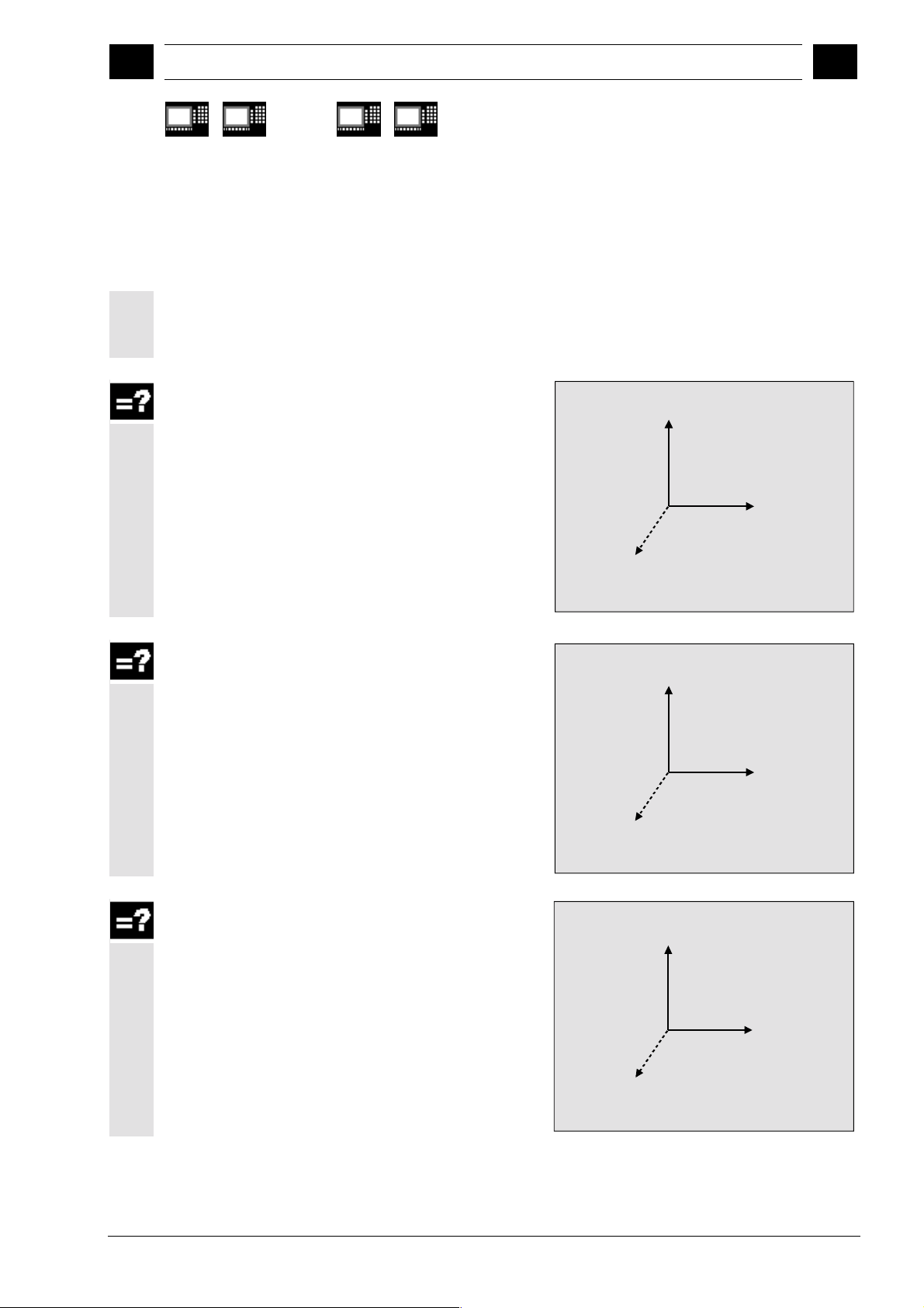
1.3 Plane definition
Tool radius compensation planes G17, G18 or G19 can
be selected. Lengths 1, 2 and 3 are assigned as follows
to the axes depending on the tool type used:
G17 plane
Tool type 100
Length 1 applies to Z
Length 2 applies to Y
Length 3 applies to X
840 D
NCU 572
NCU 573
810 D 840Di
Y
Ordinate
Abscissa X
Z
Applicate
G18 plane
Tool type 100
Length 1 applies to Y
Length 2 applies to X
Length 3 applies to Z
G19 plane
Tool type 100
Length 1 applies to X
Length 2 applies to Z
Length 3 applies to Y
X
Ordinate
Abscissa Z
Y
Applicate
Z
Ordinate
Abscissa Y
X
Applicate
Siemens AG, 2002. All rights reserved
SINUMERIK 840D/840Di/810D User's Guide Measuring Cycles (BNM) – 11.02 Edition 1-19
Page 20

Introduction 12.97
1
1.4 Suitable probes
1
840 D
NCU 571
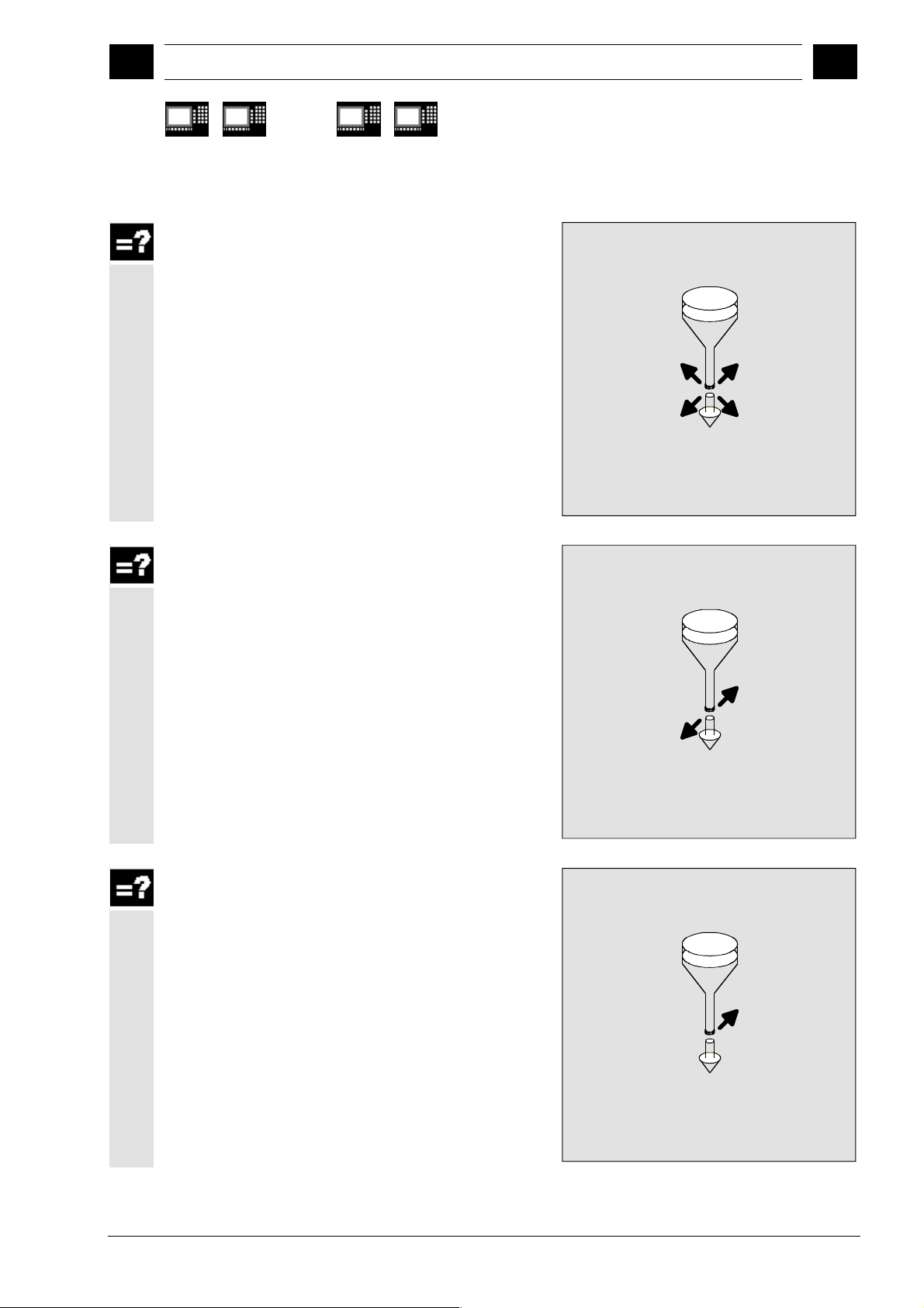
1.4 Suitable probes
Function
In order to measure tool and workpiece dimensions, a
touch-trigger probe is required that supplies a constant
signal (rather than a pulse) when deflected.
The probe must be capable of virtually bounce-free
switching. This is normally achieved by adjusting the
probe mechanically.
The probe type is defined in the measuring cycles in a
parameter.
Various types of probes made by different
manufacturers are available on the market. Probes are
classified in three groups according to the number of
directions in which they can be deflected.
Classification of probe types
Probe type Turning machines Milling mach. and mach. centers
Multidirectional
Bidirectional
Monodirectional
While a bidirectional probe can be used for turning
machines, with milling machines and machining centers
it is also possible to use a mono probe for workpiece
measuring.
The probe is defined in the measuring cycles in a
parameter.
840 D
NCU 572
NCU 573
Tool measurement Workpiece measurement Workpiece measurement
X X X
- X X
- - X
810 D 840Di
1-20 SINUMERIK 840D/840Di/810D User's Guide Measuring Cycles (BNM) – 11.02 Edition
Siemens AG, 2002. All rights reserved
Page 21
12.97 Introduction
1
1.4 Suitable probes
1
840 D
NCU 571
Multidirectional probe (3D)
With this type, measuring cycles for workpiece
measurement can be used without limitation.
Bidirectional probe
This probe type is used for workpiece measurement on
milling machines and machining centers.
This probe type is treated in the same way as a
monodirectional probe for workpiece measurement on
milling machines and machining centers.
840 D
NCU 572
NCU 573
810 D 840Di
Monodirectional probe
Siemens AG, 2002. All rights reserved
SINUMERIK 840D/840Di/810D User's Guide Measuring Cycles (BNM) – 11.02 Edition 1-21
This probe type can only be used for workpiece
measurement on milling machines and machining
centers with slight limitations; reference is made to this
in the cycles concerned.
In order to be able to use this type of probe on milling
machines and machining centers, it must be possible to
position the spindle with the NC function SPOS and to
transmit the switching signal of the probe through 360°
to the receiving station (at the machine column).
Page 22
Introduction 12.97
y
y
1
1.5 Workpiece probe, calibration tool in TO memor
1
840 D
NCU 571
The probe must be mechanically aligned in the spindle in
such a way that measurements can be taken in the following directions at the 0 degree position of the spindle.
X-Y plane G17 positive X direction
Z-X plane G18 positive Z direction
Y-Z plane G19 positive Y direction
The measurement will take longer when using a
1.5 Workpiece probe, calibration tool in TO memory
1.5.1 Workpiece probe in TO memory for milling machines and machining centers
monodirectional probe since the spindle must be
positioned in the cycle several times by means of SPOS.
Workpiece probe
On milling machines and machining centers, the probe
is classified as tool type 1x0 and must therefore be
entered as such in the TO memory.
In SW 4 and higher, tool type 710 (3D probe) can also
be used.
Entry in TO memory
840 D
NCU 572
NCU 573
810 D 840Di
P1 710 Tool type
P3 L1 Geometr
P6 r Geometry
P21 L1 Tool base dimension
L1
L1
_CBIT[14]=1
_CBIT[14]=0
r
1-22 SINUMERIK 840D/840Di/810D User's Guide Measuring Cycles (BNM) – 11.02 Edition
Siemens AG, 2002. All rights reserved
Page 23
12.97 Introduction
y
11.02
1
1.5 Workpiece probe, calibration tool in TO memor
1
840 D
NCU 571
1.5.2 Workpiece probe, calibration tool in TO memory on turning machines
840 D
NCU 572
NCU 573
810 D 840Di
On turning machines, the probes are treated as tool
type 500 with the permissible tool edge positions 5 to 8
and must therefore be entered like this in the TO
memory. Measuring cycle SW 6.2 and higher also
allows you to enter probe type 580 with tool edge
positions 5 to 8. Due to their spatial positions, the
probes are divided into the following types:
Workpiece probe SL 5
Entry in TO memory
P1 500 Tool type
P2 5 Tool edge position
P3 L1 Geometry
F
P4 L2 Geometry
P6 r Geometry
P12 L1 Wear
P13 L2 Wear
L2
P15 r Wear
P21 L1 Tool base dimension
P22 L2 Tool base dimension
r
L1
Workpiece probe SL 6 (8)
(data in brackets is in front of turning center)
Entry in TO memory
L2
r
P1 500 Tool type
P2 6 (8) Tool edge position
P3 L1 Geometry
P4 L2 Geometry
P6 r Geometry
L1
F
P12 L1 Wear
P13 L2 Wear
P15 r Wear
P21 L1 Tool base dimension
P22 L2 Tool base dimension
Siemens AG, 2002. All rights reserved
SINUMERIK 840D/840Di/810D User's Guide Measuring Cycles (BNM) – 11.02 Edition 1-23
Page 24
Introduction 12.97
y
1
1.5 Workpiece probe, calibration tool in TO memor
1
840 D
NCU 571
Workpiece probe SL 7
Entry in TO memory
840 D
NCU 572
NCU 573
810 D 840Di
P1 500 Tool type
P2 7 Tool edge position
P3 L1 Geometry
L1
F
r
P4 L2 Geometry
P6 r Geometry
P12 L1 Wear
L2
P13 L2 Wear
P15 r Wear
P21 L1 Tool base dimension
P22 L2 Tool base dimension
Workpiece probe SL 8 (6)
(data in brackets is in front of turning center)
Entry in TO memory
P1 500 Tool type
P2 8 (6) Tool edge position
P3 L1 Geometry
F
P4 L2 Geometry
P6 r Geometry
L1
P12 L1 Wear
P13 L2 Wear
P15 r Wear
P21 L1 Tool base dimension
P22 L2 Tool base dimension
r
L2
Calibration tool
On turning machines, the calibration tool is classified as
a tool with tool edge position 3 and must therefore be
entered as such in the TO memory.
Entry in TO memory
P1 500 Tool type
P2 3 Tool edge position
L1
r
F
P3 L1 Geometry
P4 L2 Geometry
P6 r Geometry
L2
P12 L1 Wear
P13 L2 Wear
P15 r Wear
P21 L1 Tool base dimension
P22 L2 Tool base dimension
Siemens AG, 2002. All rights reserved
1-24 SINUMERIK 840D/840Di/810D User's Guide Measuring Cycles (BNM) – 11.02 Edition
Page 25
12.97 Introduction
1
1.6 Measuring principle
1
840 D
NCU 571
1.6 Measuring principle
840 D
NCU 572
NCU 573
810 D 840Di
Two inputs for the connection of touch trigger probes
are provided on the I/O device interface of the
SINUMERIK 840D and the FM-NC control systems.
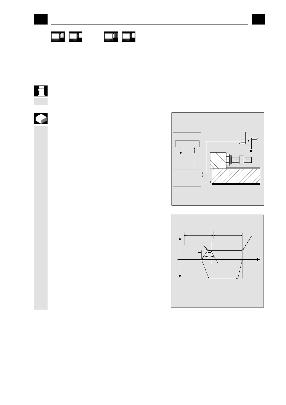
Function
Evaluation of the measuring probe signal
If a measuring point is to be approached, a traverse
command is transmitted to the position control loop and
the probe is moved towards the measuring point. A
point behind the expected measuring point is defined as
setpoint position. As soon as the probe makes contact,
the actual axis value at the time the switching position is
reached is measured and the drive is stopped. The
remaining "distance-to-go" is deleted.
NC
Meas. cycle
Delete
distanceto-go
Act. val. acquis.
Position control
Actual
value
"On-the-fly" measurement
The principle of "on-the-fly" measurement is
implemented in the control. The advantage of this
method is that the probe signal is processed directly in
the NC.
Set position
Meas. dist. a
V
Delete
dist.-to-go
-V
S
=Traversing path by signal processing
1
=Following error
S
2
1) Actual value loaded with probe signal
Meas. dist. a
Act. position
S
2
S
1
Probe switching
point
1)
G0
Start position
= End position
G0
Siemens AG, 2002. All rights reserved
SINUMERIK 840D/840Di/810D User's Guide Measuring Cycles (BNM) – 11.02 Edition 1-25
Page 26

Introduction 12.97
1
1.6 Measuring principle
1
840 D
NCU 571
Start position/setpoint position
In the measuring procedure used, a position is specified
as setpoint value for the cycle at which the signal of the
touch-trigger probe is expected.
Since it is unlikely that the probe will respond at
precisely this point, the start position is approached by
the control in rapid traverse mode or at a defined
positioning velocity. The set position is then approached
at the feedrate specified in the parameter for
measurement speed. The switching signal is then
anticipated over a distance of a maximum length of 2a
from the start position.
Load actual value/delete distance-to-go
At the instant the switching signal is output by the
probe, the current position is stored internally "on-thefly" as the actual value followed by execution of the
"Delete distance-to-go" function.
Measuring path a/measuring speed
The path increment a is normally 1 mm, but can be
increased with a parameter when measuring cycles are
called.
The approach speed automatically increases from
150 mm/min to 300 mm/min if the value for a is defined
as greater than 1.
The maximum approach speed (measurement speed)
is thus dependent upon
• the permissible deflection path of the probe used
• the delay until "delete distance to go" is executed
• the deceleration behavior of the axis.
and
840 D
NCU 572
NCU 573
810 D 840Di
1-26 SINUMERIK 840D/840Di/810D User's Guide Measuring Cycles (BNM) – 11.02 Edition
Siemens AG, 2002. All rights reserved
Page 27
12.97 Introduction
11.02
1
1.6 Measuring principle
1
840 D
NCU 571
Calculation of the deceleration path
840 D
NCU 572
NCU 573
810 D 840Di
Since an optimal measurement speed can be set for
measuring cycles via a parameter, it must be ensured
that safe deceleration can take place within the
deflection path of the probe.
The required deceleration path can be calculated as
follows:
2
sb = v t +
s
b
Deceleration path in m
v
·
s
∆
1
2a
+ ∆s
∆
s
2
v Approach speed in m/s
t Delay in s
b Deceleration in m/s
2
s Following error in m
Measuring accuracy
The repeat accuracy of the 840D and FM-NC controls
for "on-the-fly measurement" is ±1 µm.
The measuring accuracy which can be obtained is thus
dependent on the following factors:
• Repeat accuracy of the machine
• Repeat accuracy of the probe
• Resolution of the measuring system
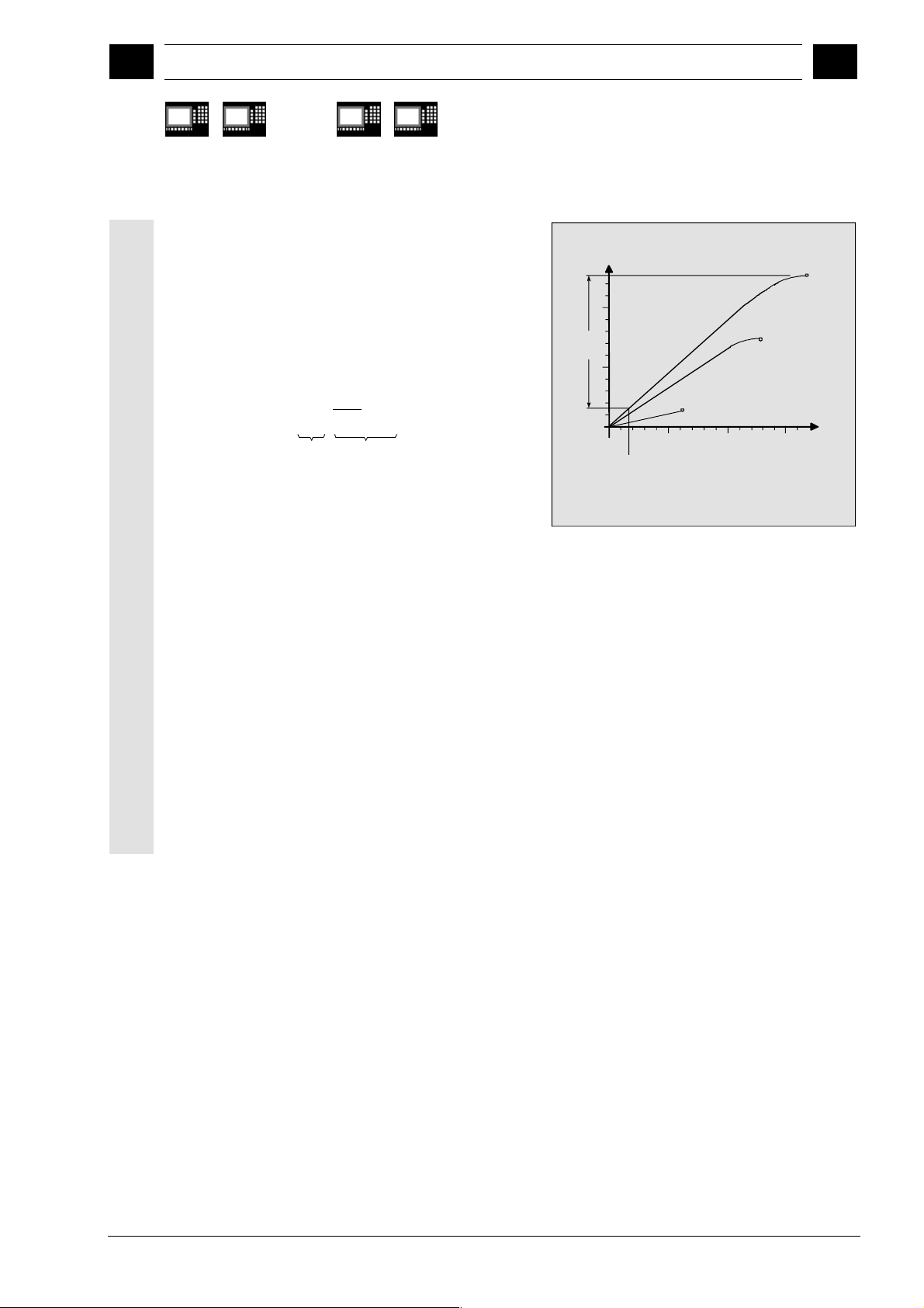
Example: Path-time diagram
s [mm]
Deceleration
2
b = 1m/s
10
Ds
2
(11 mm)
Ds
1
(1.66 mm)
The deflection of the probe up to zero spee d of the axis is
approximately 12.6 mm with an approach speed of 6 m/min
and a delay of 1 m/s
Kv-Factor
1m/min
=
K
v
5
min
Zero speed
0
1 m/min
10
(16 ms) Delay until distance-to-go is deleted
2
!
6 m/min
Approach speed v
4 m/min
10 10
Axis
zero speed
Zero speed
t [ms]
Siemens AG, 2002. All rights reserved
SINUMERIK 840D/840Di/810D User's Guide Measuring Cycles (BNM) – 11.02 Edition 1-27
Page 28

Introduction 12.97
1
1.7 Measuring strategy and compensation value calculation for tools
08.99
1
840 D
NCU 571
1.7 Measuring strategy and compensation value calculation for tools with automatic tool
840 D
NCU 572
NCU 573
810 D 840Di
offset
The actual workpiece dimensions must be measured
exactly in order to be able to determine and
compensate the actual dimensional deviations on the
workpiece.
Function
When taking measurements on the machine, the actual
dimensions are derived from the path measuring
systems of the position-controlled feed axes. For each
dimensional deviation determined from the set and
actual workpiece dimensions there are many causes
which essentially can be classified in 3 categories:
• Dimensional deviations with causes that are
n o t subject to a particular trend,
scatter of the feedforward axes or differences in
measurement between the internal measurement
(measuring probe) and the external measuring
device (micrometer, measuring equipment, etc.).
In this case, it is possible to apply so-called
empirical values, which are stored in separate
memories. The set/actual difference determined is
automatically compensated by the empirical value.
• Dimensional deviations with causes that a r e
subject to a particular trend
thermal expansion of the leadscrew.
These deviations are compensated by specifying
fixed threshold values.
• Accidental dimensional deviations, e.g. due to
temperature fluctuations, coolant or slightly soiled
measuring points.
, e.g. tool wear or
e.g. positioning
1-28 SINUMERIK 840D/840Di/810D User's Guide Measuring Cycles (BNM) – 11.02 Edition
Siemens AG, 2002. All rights reserved
Page 29

12.97 Introduction
1
1.7 Measuring strategy and compensation value calculation for tools
1
840 D
NCU 571
840 D
NCU 572
NCU 573
810 D 840Di
Assuming the ideal case, only those dimensional
deviations which are subject to a trend can be taken
into account for compensation value calculation. Since,
however, it is hardly ever known to what extent and in
which direction accidental dimensional deviations
influence the measurement result, a strategy (floating
average value generation) is needed which derives a
compensation value from the actual/set difference
measured.
Mean value calculation
Mean value calculation in combination with a higherorder measurement weighting has proved a suitable
means to do this.
The formula of the mean value generation chosen is:
Mv D
−
Mv Mv
=−
new old
old i
k
Mv
Mv
Mean value new = amount of compensation
new
Mean value prior to last measurement
old
k Weighting factor for average value calculation
D
Actual/set difference measured
i
(minus empirical value, if any)
The mean value calculation takes account of the trend
of the dimensional deviations of a machining series,
weighting factor k from which the mean value is
where
derived is selectable.
A new measurement result affected by accidental
dimensional deviations only influences the new tool
offset to some extent, depending on the weighting
factor.
Siemens AG, 2002. All rights reserved
SINUMERIK 840D/840Di/810D User's Guide Measuring Cycles (BNM) – 11.02 Edition 1-29
Page 30
Introduction 12.97
1
1.7 Measuring strategy and compensation value calculation for tools
08.99
1
840 D
NCU 571
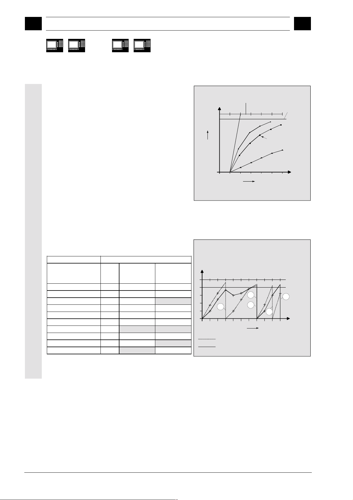
Computational characteristic of the mean value
840 D
NCU 572
NCU 573
810 D 840Di
with different weightings k (effects)
• The greater the value of k, the slower the formula
will respond when major deviations occur in
computation or counter compensation. At the same
time, however, accidental scatter will be reduced as
k increases.
• The lower the value of k, the faster the formula will
react when major deviations occur in computation or
counter compensation. However, the effect of
accidental variations will be that much greater.
• The mean value Mv is calculated starting at 0 over
the number of workpieces i, until the calculated
average value exceeds the range of "zero
compensation". From this limit on, the calculated
average value is applied for compensation.
Example of mean value generation
Lower limit = 40 µm
D
[µm]
Mean value
i
k=3
[µm]
Mean value
k=2
[µm]
1st measurement 30 10 15
2nd measurement 50 23.3 32.5
3rd measurement 60 35.5 46.2
4th measurement 20 30.3 10
5th measurement 40 32.6 25
6th measurement 50 38.4 37.5
7th measurement 50 42.3
43.75
8th measurement 30 10 15
9th measurement 70 30 42.5
10th measurement 70 43.3
35
Set/actual difference
D
i
Mean
value
calculated
Setpoint
1234 560
Characteristic of mean values
with two different weighting factors k
D
i
50
40
30
20
10
3
12345678910
k=2
k=3
Lower limit = "Zero offset"
k=1
k=2
k=3
Number of averaging operations
(workpieces)
1
4
Number of averaging operations
(workpieces)
Mean value
calculated
k=10
Set/actual difference
Zero compensation
2
5
1-30 SINUMERIK 840D/840Di/810D User's Guide Measuring Cycles (BNM) – 11.02 Edition
Siemens AG, 2002. All rights reserved
Page 31

12.97 Introduction
08.99
1
1.8 Parameters for checking the dim. deviation and compensation
1
840 D
NCU 571
1.8 Parameters for checking the dim. deviation and compensation
Explanation
For constant deviations not subject to a trend the
dimensional deviation measured can be compensated
by an empirical value for certain measurement variants.
For other compensations resulting from dimensional
deviations, symmetrical tolerance bands are assigned
to the set dimension which result in different responses.
Empirical value _EVNUM
The empirical values are used to suppress dimensional
deviations
The empirical values are stored in the GUD field
_EV empirical value.
_EVNUM specifies the number of the empirical value
memory. The actual/set difference determined by the
measuring cycle is corrected by this value
further correction measures are taken.
This is the case
• for workpiece measurement with automatic tool
• for tool measurement
• for single-point measurement with automatic
The tolerance bands (range of permissible dimensional
tolerance) and the responses derived from them have
been specified as follows:
840 D
NCU 572
NCU 573
that are not subject to a trend.
offset
ZO compensation
810 D 840Di
before any
Siemens AG, 2002. All rights reserved
SINUMERIK 840D/840Di/810D User's Guide Measuring Cycles (BNM) – 11.02 Edition 1-31
Page 32

Introduction 12.97
1
1.8 Parameters for checking the dim. deviation and compensation
05.98
1
840 D
NCU 571
•
840 D
NCU 572
NCU 573
810 D 840Di
For workpiece measurement with automatic
tool offset
_TSA
_TDIF
_TLL, _TUL
_TMV
_TZL
Safe area
Dimensional difference check
Workpiece tolerance
2/3 workpiece tolerance
Zero compensation (lower limit)
Setpoint
Alarm: "Safe area overrun"
Alarm: "Permissible dimensional difference overrrun"
Compensation of current
deviation
Alarm: "Oversize", "Undersize"
Compensation of current
deviation
Averaging (_EVNUM, _K) and
compensation by mean value
Averaging is stored
The workpiece set dimension is placed in the center
of the permissible ± tolerance limit applied.
For tool measurement
•
_TSA
_TDIF
_TZL
Safe area
Dimensional difference check
Zero compensation (lower limit)
Setpoint = Tool data
Alarm: "Safe area overrun"
Alarm: "Permissible dimensional difference overrun"
Tool memory is
compensated
Tool memory
unchanged
1-32 SINUMERIK 840D/840Di/810D User's Guide Measuring Cycles (BNM) – 11.02 Edition
Siemens AG, 2002. All rights reserved
Page 33

12.97 Introduction
05.98
1
1.8 Parameters for checking the dim. deviation and compensation
1
840 D
NCU 571
•
840 D
NCU 572
NCU 573
810 D 840Di
For workpiece measurement with zero offset
_TSA
Safe area
Setpoint
For workpiece probe calibration
•
_TSA
Safe area
Alarm: "Safe area overrun"
Compensation of
ZO memory
Alarm: "Safe area overrun"
_TZL
Zero compensation (lower limit)
Setpoint =_WP[]-data
For tool probe calibration
•
_TSA
_TZL
Safe area
Zero compensation (lower limit)
Setpoint=_TP[]-data
_WP[] data is compensated
_WP[] data
unchanged
Alarm: "Safe area overrun"
_TP[] data is compensated
_TP[] data
unchanged
Siemens AG, 2002. All rights reserved
SINUMERIK 840D/840Di/810D User's Guide Measuring Cycles (BNM) – 11.02 Edition 1-33
Page 34

Introduction 12.97
1
1.8 Parameters for checking the dim. deviation and compensation
08.99
1
840 D
NCU 571
Safe area _TSA
The safe area is active for all measurement variants
and does not affect the offset value; it is used for
diagnosis.
If this value is reached,
• a defect in the probe,
• an incorrect setpoint position or
• an illegal deviation from the setpoint position
may be the cause.
AUTOMATIC operation is interrupted and the program
cannot continue. An alarm text appears to warn the
user.
Dimensional difference control _TDIF
_TDIF is active only for workpiece measurement with
automatic tool offset and for tool measurement.
This limit has no effect on generation of the
compensation value either. When it is reached, the tool
is probably worn and needs to be replaced.
840 D
NCU 572
NCU 573
810 D 840Di
An alarm text is displayed to warn the operator and the
This tolerance limit is generally used by the PLC for tool
program can be continued by means of an NC start.
management purposes (twin tools, wear monitoring).
Tolerance of the workpiece _TLL, _TUL
Both parameters are active only for tool measurement
with automatic tool offset.
When measuring a dimensional deviation ranging
between "2
difference control", this is regarded 100% as tool
compensation. The previous average value is erased.
It is therefore possible to effect fast counteraction if
major dimensional deviations occur.
/3 tolerance of workpiece" and "Dimensional
1-34 SINUMERIK 840D/840Di/810D User's Guide Measuring Cycles (BNM) – 11.02 Edition
Siemens AG, 2002. All rights reserved
Page 35

12.97 Introduction
08.99
1
1.8 Parameters for checking the dim. deviation and compensation
1
840 D
NCU 571
840 D
NCU 572
NCU 573
810 D 840Di
AUTOMATIC operation is interrupted when the tolerance
limit of the workpiece is exceeded. "Oversize" or
"undersize" is displayed to the operator depending on the
tolerance zone position. Machining can be continued by
means of NC start.
2/3 workpiece tolerance _TMV
_TMV is active only for workpiece measurement with
automatic tool offset.
Within the range of "Lower limit" and "2
/3 workpiece
tolerance" the mean value is calculated according to the
formula described in Section "Measuring strategy".
Mv
• If Mv
is compared with the zero compensation range:
new
is greater than this range, compensation is
new
corrected by Mv
and the associated mean value
new
memory is cleared.
• If Mv
is less than this range, no compensation is
new
carried out to prevent excessively abrupt
compensations from being made.
Mean value_EVNUM
_EVNUM is active only for workpiece measurement with
automatic tool offset.
When calculating the mean value in a series of
machining operations, the mean value determined by the
measurement at the same measurement location on the
previous workpiece can be taken into account
(_CHBIT[4]=1).
The mean values are stored in the GUD field
values
. _EVNUM also specifies the number of the mean
value memory in this GUD field.
Weighting factor for mean value calculation _K
_K is active only workpiece measurement with automatic
tool offset. The weighting factor k can be applied to allow
different weighting to be given to an individual
measurement.
A new measurement result thus has only a limited effect
on the new tool offset as a function of _K.
_MV mean
Siemens AG, 2002. All rights reserved
SINUMERIK 840D/840Di/810D User's Guide Measuring Cycles (BNM) – 11.02 Edition 1-35
Page 36

Introduction 12.97
1
1.8 Parameters for checking the dim. deviation and compensation
1
840 D
NCU 571
Bottom limit (zero compensation area) _TZL
_TZL active for
• Workpiece measurement with automatic tool offset
• Tool measurement and calibration for milling tools
This tolerance range corresponds to the amount of
maximum accidental dimensional deviations. It has to
be determined for each machine.
No tool compensation is made within these limits.
However, the average value of this measuring point is
updated and re-stored with the actual/set difference
measured for workpiece measurement with automatic
tool offset, compensated by an empirical value if
necessary.
840 D
NCU 572
NCU 573
and tool probes
810 D 840Di
1-36 SINUMERIK 840D/840Di/810D User's Guide Measuring Cycles (BNM) – 11.02 Edition
Siemens AG, 2002. All rights reserved
Page 37

12.97 Introduction
05.98
1
1.9 Effect of empirical value, mean value and tolerance parameters
1
840 D
NCU 571
1.9 Effect of empirical value, mean value and tolerance parameters
840 D
NCU 572
NCU 573
810 D 840Di
The following flowchart shows the effect of empirical
value, mean value and tolerance parameters by way of
a workpiece measurement with automatic tool offset.
Measuring cycle
Measure
Calculate act/set difference
Difference
minus
empirical value
No
Difference >
safe area _TSA
Yes
No
Compensation strategy
Calculate mean value considering
weighting factor _K
Mean value >
lower limit _TZL
Store mean value
(only for _CHBIT[4]=1)
No
Difference >
workpiece tol.
_TUL/_TLL
Difference >
2/3 workpiece
tol. _TMV
Smoothed
YesNo
compensation
Compensation
by mean value
Delete
mean value
Difference >
dimensional diff.
control _TDIF
Yes
Display:
Oversize
or
undersize
100 % compens.
YesNo
Delete
mean value
Compensation
by difference
Yes
Display:
Permiss. Dimensional difference
exceeded
Repeat
measurement
No
Alarm 61303
Alarm:
Safe area
exceeded
Display:
Safe area
exceeded
No
Yes
Yes
End
Siemens AG, 2002. All rights reserved
SINUMERIK 840D/840Di/810D User's Guide Measuring Cycles (BNM) – 11.02 Edition 1-37
Page 38

Introduction 12.97
1
1.10 Reference points on the machine and workpiece
1
840 D
NCU 571
840 D
NCU 572
NCU 573
810 D 840Di
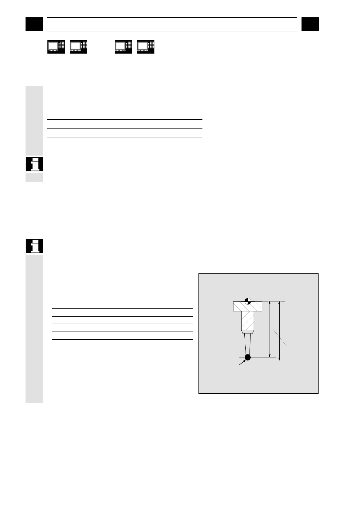
1.10 Reference points on the machine and workpiece
Function
The actual axis values of different actual value
systems must be measured depending on the
measuring process applied. While, for example, the
machine actual value can be used to advantage to
calculate the tool length, the workpiece zero is
important for measuring workpiece dimensions and
calculating the tool wear compensation. The
machine actual value is the dimension between the
machine zero and the tool reference point.
M = Machine zero
M' = Machine zero offset by DRF
C = Control zero resulting from PRESET offset
W = Workpiece zero
F = Tool reference point
Y
Spindle
chuck
MM'C W
Workpiece
X
PF
F
Y
PF
X
1-38 SINUMERIK 840D/840Di/810D User's Guide Measuring Cycles (BNM) – 11.02 Edition
Siemens AG, 2002. All rights reserved
Page 39
12.97 Introduction
1
1.11 Measurement variants for milling machines & machining centers
1
840 D
NCU 571
1.11 Measurement variants for milling machines & machining centers
840 D
NCU 572
NCU 573
810 D 840Di
The measurement variants which can be implemented
with measuring cycles for milling machines and
machining centers are illustrated in diagrams below.
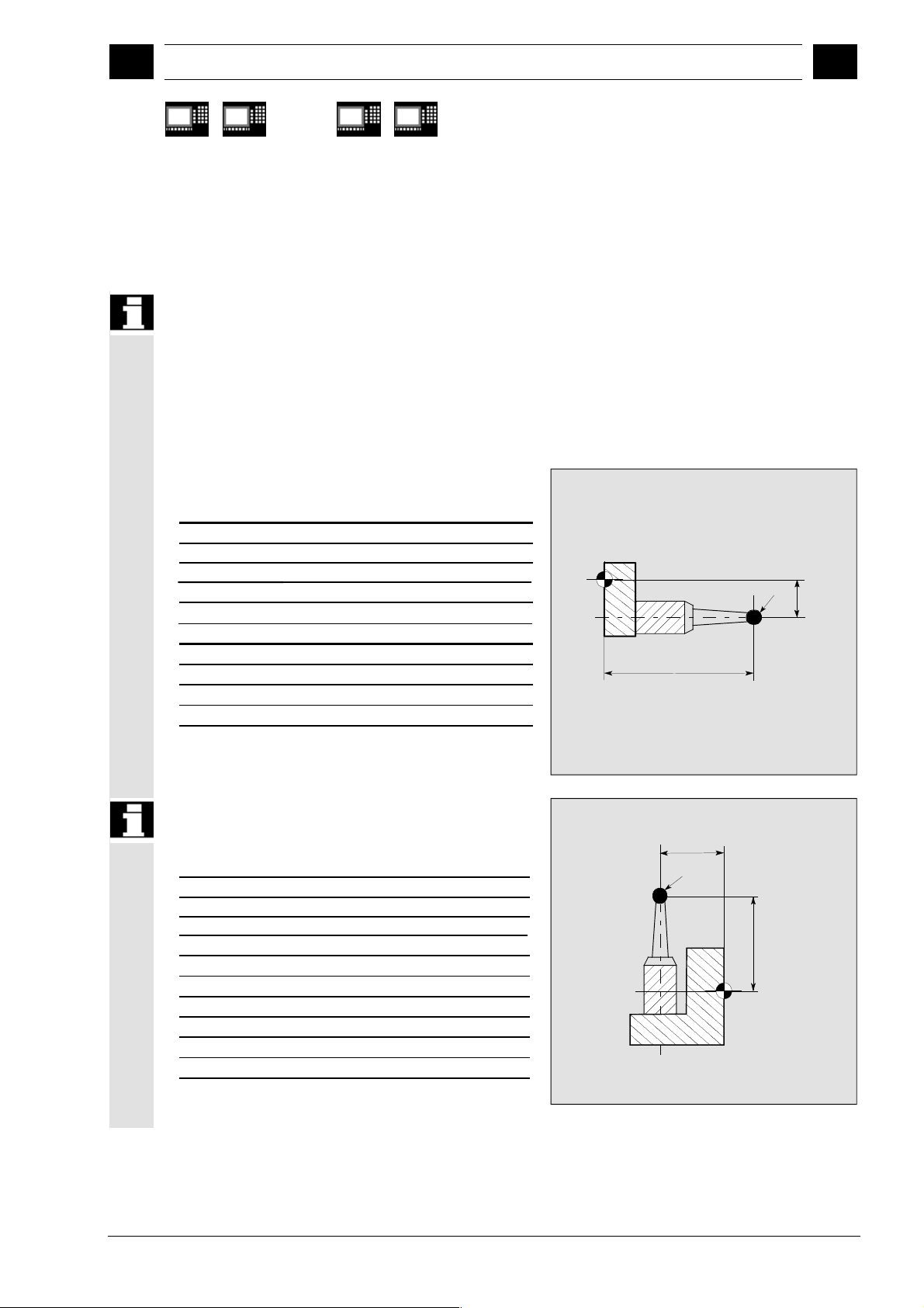
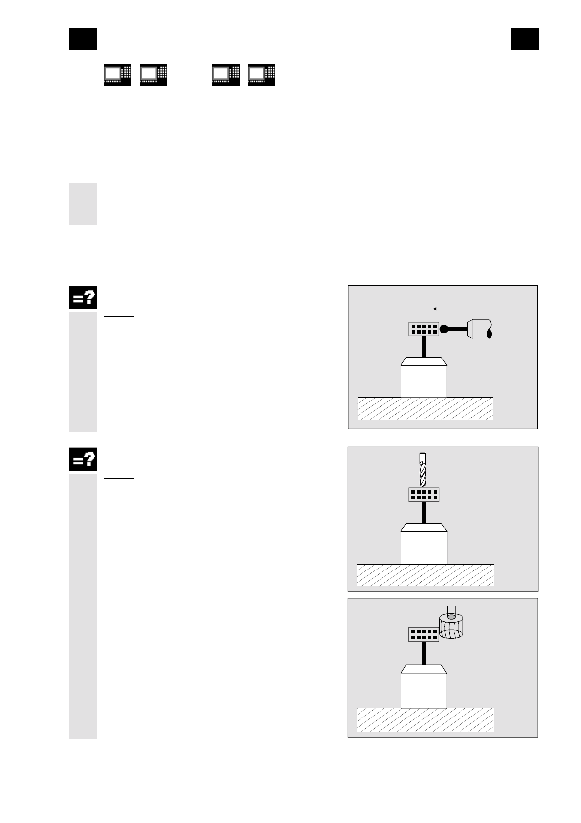
1.11.1 Workpiece measurement for milling machines
Tool probe calibration
Result:
Probe switching point with reference to machine zero
Calibration tool
Measuring the tool
Result:
Tool length
Length
Drill
Tool radius
Radius
Mill
Siemens AG, 2002. All rights reserved
SINUMERIK 840D/840Di/810D User's Guide Measuring Cycles (BNM) – 11.02 Edition 1-39
Page 40

Introduction 12.97
1
1.11 Measurement variants for milling machines & machining centers
1
840 D
NCU 571
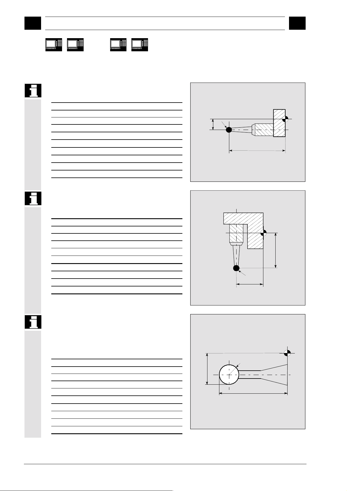
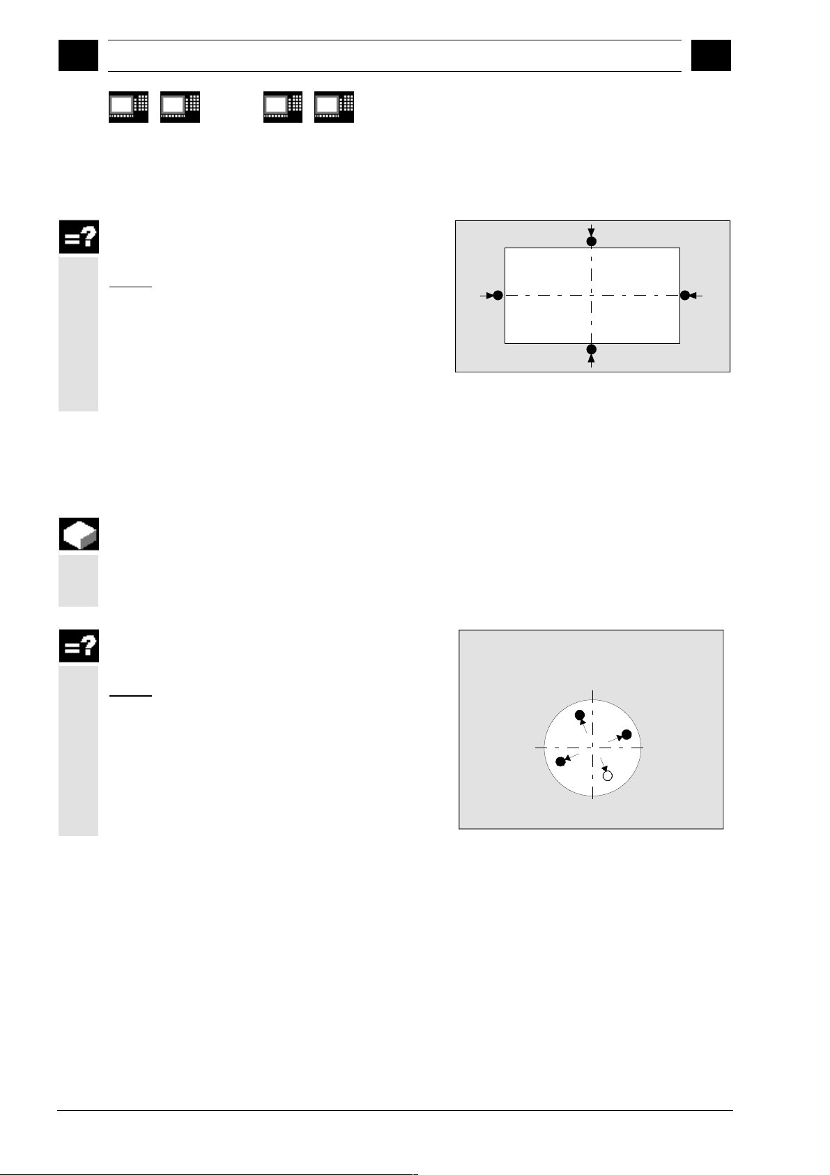
1.11.2 Measurement variants for fast measurement at a single point
Function
CYCLE978 makes it easy to take a measurement at
one point of a surface.
The measuring point is approached paraxially.
Depending on the measurement variant, the result may
influence the selected tool offset or zero offset.
Workpiece measurement, blank measurement
Result:
Position, deviation,
Zero offset
840 D
NCU 572
NCU 573
810 D 840Di
W
Workpiece measurement, single-point
1.11.3 Measurement variants for workpiece measurement paraxial
measurement
Result:
Actual dimension, deviation,
tool offset
Function
The following measurement variants are provided for
the paraxial measurement of a hole, shaft, groove or
web. They are executed by the cycle CYCLE977.
1-40 SINUMERIK 840D/840Di/810D User's Guide Measuring Cycles (BNM) – 11.02 Edition
Siemens AG, 2002. All rights reserved
Page 41

12.97 Introduction
1
1.11 Measurement variants for milling machines & machining centers
1
840 D
NCU 571
Workpiece measurement, measuring the hole
Result:
Actual dimension (diameter),
deviation, center point,
tool offset,
zero offset
Workpiece measurement, measuring the shaft
Result:
Actual dimension (diameter),
deviation, center point,
tool offset,
zero offset
Workpiece measurement, measuring the
groove
840 D
NCU 572
NCU 573
810 D 840Di
Result:
Actual dimension (groove width),
deviation, groove center,
tool offset,
zero offset
Workpiece measurement, measuring the web
Result:
Actual dimension (web width),
deviation, web center,
tool offset,
zero offset
Workpiece measurement, measuring the
inside rectangle
Result:
Actual value rectangle length and width,
actual dimension rectangle center,
deviation rectangle length and width,
deviation rectangle center,
tool offset,
zero offset
Siemens AG, 2002. All rights reserved
SINUMERIK 840D/840Di/810D User's Guide Measuring Cycles (BNM) – 11.02 Edition 1-41
Page 42
Introduction 12.97
1
1.11 Measurement variants for milling machines & machining centers
1
840 D
NCU 571
Workpiece measurement, measuring the
1.11.4 Measurement variants for workpiece measurement at random angles
outside rectangle
Result:
Actual value rectangle length and width,
actual dimension rectangle center,
deviation rectangle length and width,
deviation rectangle center,
tool offset,
zero offset
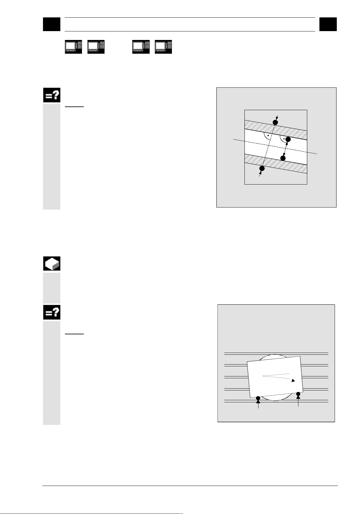
Function
840 D
NCU 572
NCU 573
810 D 840Di
The following measurement variants are provided for
the measurement of a bore, shaft, groove or web at
random angles. They are executed by CYCLE979.
Triple-point (quadruple-point) measurement at
random angles
Result:
Actual dimension (diameter),
deviation, center point,
tool offset,
zero offset
Hole, shaft, circle segment
1-42 SINUMERIK 840D/840Di/810D User's Guide Measuring Cycles (BNM) – 11.02 Edition
Siemens AG, 2002. All rights reserved
Page 43
12.97 Introduction
1
1.11 Measurement variants for milling machines & machining centers
1
840 D
NCU 571
Two-point measurement at random angles
Result:
Actual dimension (groove width, web width),
deviation, groove center, web center,
zero offset
840 D
NCU 572
NCU 573
810 D 840Di
Groove, web
1.11.5 Measuring a surface at a random angle
Function
The zero offset can be compensated after
measurement of a surface at a random angle by means
of CYCLE998.
Workpiece measurement, angular
measurement
Result:
Actual dimension (angle),
deviation,
zero offset
Angle measurement
Siemens AG, 2002. All rights reserved
SINUMERIK 840D/840Di/810D User's Guide Measuring Cycles (BNM) – 11.02 Edition 1-43
Page 44

Introduction 12.97
1
1.12 Measurement variants for lathes
1
840 D
NCU 571
1.12 Measurement variants for lathes
1.12.1 Tool measurement for lathes
Tool probe calibration
Result:
Probe switching point with reference to machine zero
840 D
NCU 572
NCU 573
810 D 840Di
Calibration tool
Measuring the tool
Result:
Tool length (length1, length2)
1-44 SINUMERIK 840D/840Di/810D User's Guide Measuring Cycles (BNM) – 11.02 Edition
Siemens AG, 2002. All rights reserved
Page 45

12.97 Introduction
05.98
1
1.12 Measurement variants for lathes
1
840 D
NCU 571
1.12.2 Workpiece measurement for turning machines: Single-point measurement
840 D
NCU 572
NCU 573
810 D 840Di
Single-point measurement outside
Result:
Actual dimension (diameter, length),
deviation,
tool offset,
zero offset
Single-point measurement inside
Calibrate
Measure
Result:
Actual dimension (diameter, length),
deviation,
tool offset,
Calibrate
zero offset
Measure
Siemens AG, 2002. All rights reserved
SINUMERIK 840D/840Di/810D User's Guide Measuring Cycles (BNM) – 11.02 Edition 1-45
Page 46
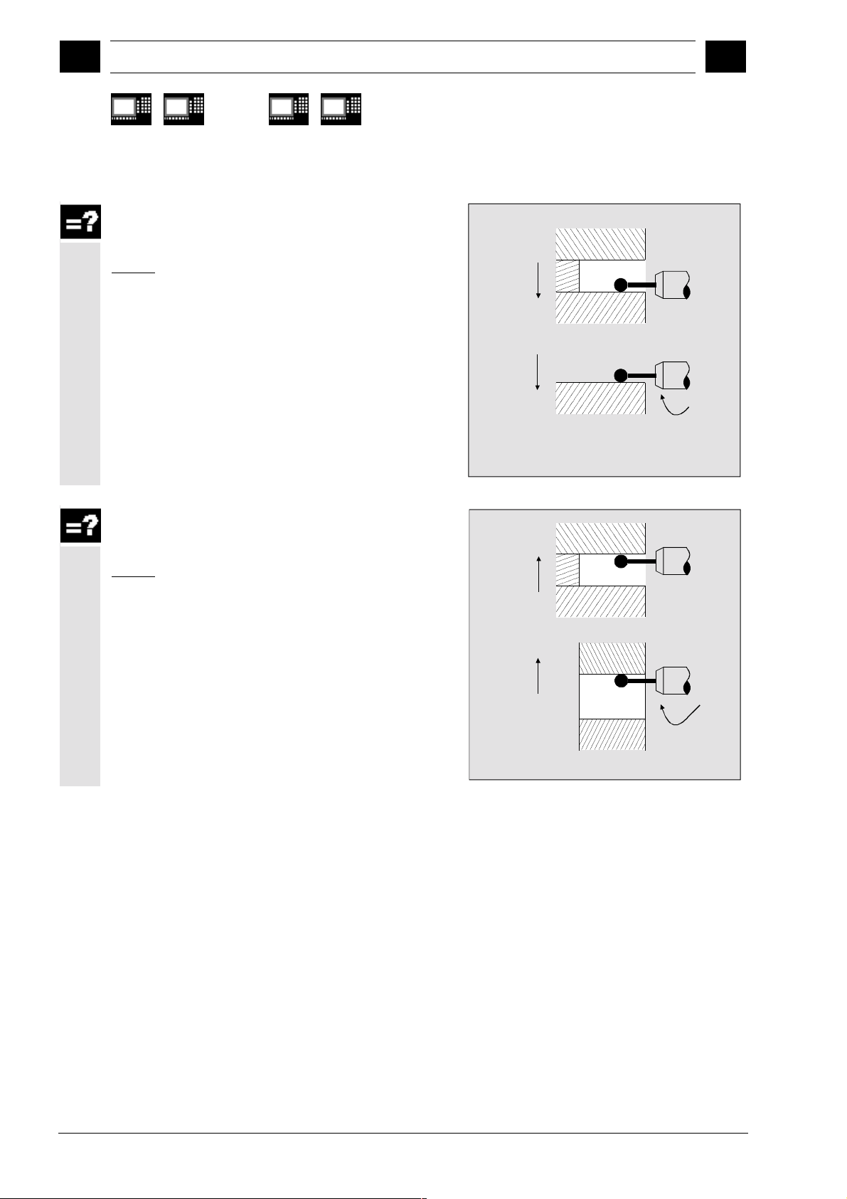
Introduction 12.97
1
1.12 Measurement variants for lathes
05.98
1
840 D
NCU 571
Single-point measurement outside with 180°°°°
reversal spindle
840 D
NCU 572
NCU 573
810 D 840Di
Result:
Actual dimension (diameter, length),
deviation,
Calibrate
tool offset
Measure
Single-point measurement inside with 180°°°°
reversal spindle
Result:
Actual dimension (diameter, length),
deviation,
tool offset
Calibrate
Measure
1-46 SINUMERIK 840D/840Di/810D User's Guide Measuring Cycles (BNM) – 11.02 Edition
Siemens AG, 2002. All rights reserved
Page 47
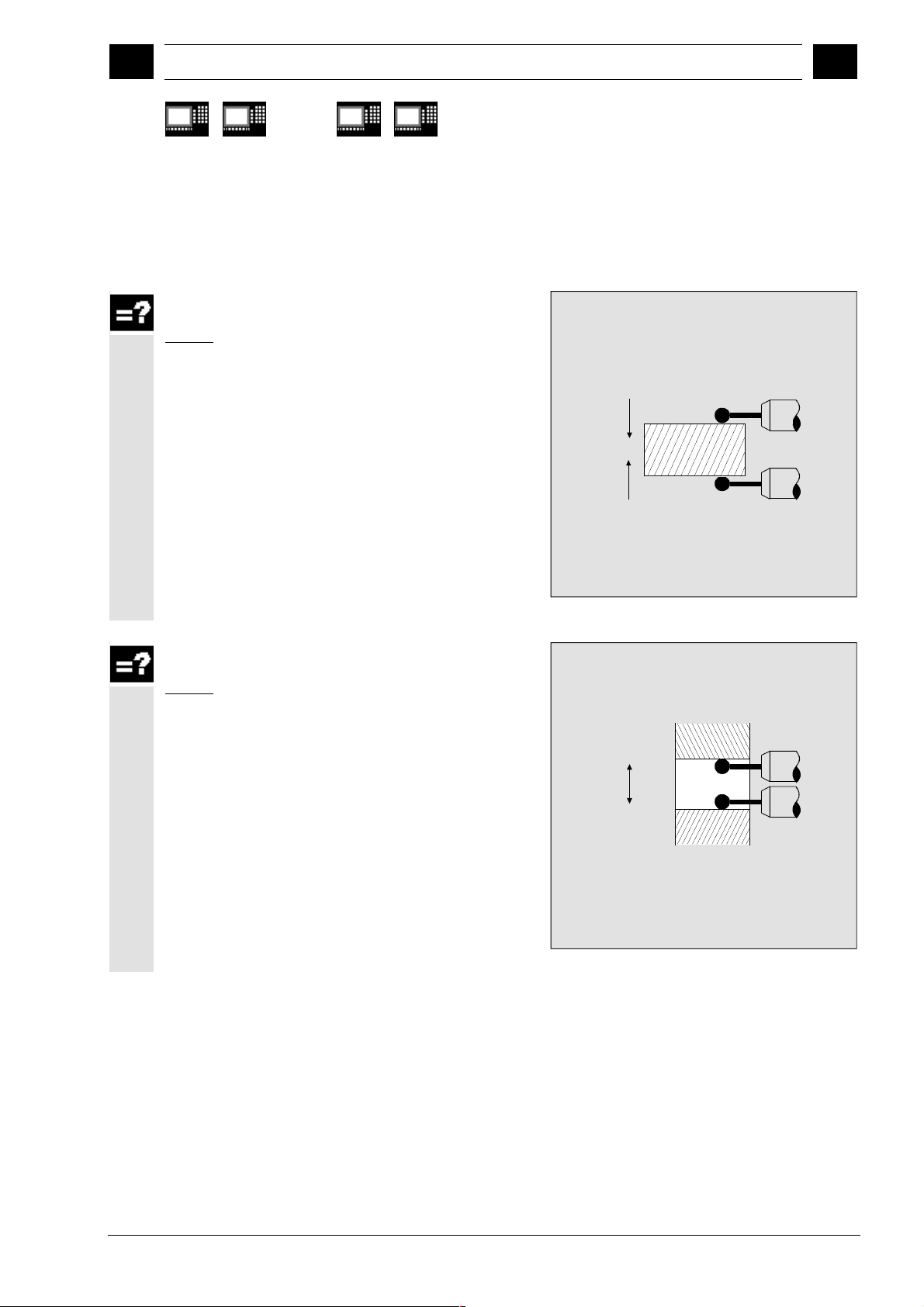
12.97 Introduction
05.98
1
1.12 Measurement variants for lathes
1
840 D
NCU 571
1.12.3 Workpiece measurement for turning machines: Two-point measurement
Two-point measurement on outside diameter
Result:
Actual dimension (diameter),
deviation,
tool offset
840 D
NCU 572
NCU 573
810 D 840Di
Two-point measurement on inside diameter
Result:
Actual dimension (diameter),
deviation,
tool offset
Siemens AG, 2002. All rights reserved
SINUMERIK 840D/840Di/810D User's Guide Measuring Cycles (BNM) – 11.02 Edition 1-47
Page 48

Introduction 12.97
1
1.13 Measuring cycles interface
1
840 D
NCU 571
1.13 Measuring cycles interface
The measuring cycles provide an interactive function for
defining input and output parameters.
Values can be assigned to the input parameters via a
help cycle in an input dialog.
The results of measurement can be displayed
automatically via another help cycle.
1.13.1 Displaying measuring result screens
Function
840 D
NCU 572
NCU 573
810 D 840Di
Depending on the configuration
Measuring results can be displayed automatically while
a measuring cycle is running.
Activation of this function depends on the configuration
of the measuring cycle interface in the MMC and the
settings in the measuring cycle data.
Observe the specifications of the machine
manufacturer.
• the measuring result displays are automatically
deselected at the end of a measuring cycle
• the measuring result displays must be
acknowledged with the NC Start key;
In this case, the measuring cycle outputs the message:
"Please acknowledge measuring result display with
NC Start"
.
1-48 SINUMERIK 840D/840Di/810D User's Guide Measuring Cycles (BNM) – 11.02 Edition
Siemens AG, 2002. All rights reserved
Page 49

12.97 Introduction
1
1.13 Measuring cycles interface
1
840 D
NCU 571
Explanation
The measuring cycles can display different measuring
result screens depending on the measurement variant:
• Tool probe calibration
• Tool measurement
• Workpiece probe calibration
• Workpiece measurement
The result displays contain the following data:
Calibrating the tool probe
− Measuring cycle and measurement variant
− Probe ball diameter and difference
− Trigger values of axis directions and differences
− Positional deviation during calibration on the plane
− Probe number
− Safe area
Tool measurement
− Measuring cycle and measurement variant
− Actual values and differences for tool offsets
− T number and D number
Calibrate tool probe
− Measuring cycle and measurement variant
− Trigger values of axis directions and differences
− Positional deviation during calibration on the plane
− Probe number
− Safe area and permissible dimensional difference
Workpiece measurement
− Measuring cycle and measurement variant
− Setpoints, actual values and their differences
− Upper and lower tolerance limits
− Offset value
− Probe number
− Safe area and permissible dimensional difference
− T number and D number or ZO memory for
840 D
NCU 572
NCU 573
automatic offset
810 D 840Di
Siemens AG, 2002. All rights reserved
SINUMERIK 840D/840Di/810D User's Guide Measuring Cycles (BNM) – 11.02 Edition 1-49
Page 50

Introduction 12.97
1
1.13 Measuring cycles interface
1
840 D
NCU 571
1.13.2 Setting parameters
Function
Values can be assigned to measuring cycle parameters
with CYCLE103.
Activation of this function depends on the configuration
of the measuring cycle interface in the MMC.
Observe the specifications of the machine
manufacturer.
Explanation
When CYCLE103 is selected and started, an input
dialog for setting parameters for the measuring cycles is
opened.
During the course of this dialog, a series of input screen
forms are opened one after the other on top of the
current display. Once the values have been entered
each display must be concluded by pressing the OK key
in the vertical softkey bar.
At the end of the dialog, the message
"Input dialog successfully completed"
is displayed in the dialog line of the control and the
display before dialog mode was activated is
reconstructed.
It is immediately possible to select and start the last
measuring cycle assigned parameters.
840 D
NCU 572
NCU 573
810 D 840Di
1-50 SINUMERIK 840D/840Di/810D User's Guide Measuring Cycles (BNM) – 11.02 Edition
Siemens AG, 2002. All rights reserved
Page 51

12.97 Introduction
1
1.13 Measuring cycles interface
1
840 D
NCU 571
Explanation
The sequence of the dialog for assigning parameters is
as follows:
• Selection of the measuring cycle to which
• Selection of the measurement variant;
• Assignment of parameters for the measurement
• Input and confirmation of generally applicable
The input values for selecting the measuring cycle and
the measurement variant are subjected to a plausibility
check and the input screen forms are repeated if
necessary.
840 D
NCU 572
NCU 573
parameters are to be assigned;
variant chosen, this could involve several input
screen forms depending on the measuring cycle;
measuring cycle data which do not usually change.
810 D 840Di
If the operating area is switched over during the course
of the input dialog, the dialog can be selected again at a
later stage with "Cycles" softkey in the extended menu.
n
Siemens AG, 2002. All rights reserved
SINUMERIK 840D/840Di/810D User's Guide Measuring Cycles (BNM) – 11.02 Edition 1-51
Page 52

Introduction 12.97
1
1.13 Measuring cycles interface
1
Notes
840 D
NCU 571
840 D
NCU 572
NCU 573
810 D 840Di
1-52 SINUMERIK 840D/840Di/810D User's Guide Measuring Cycles (BNM) – 11.02 Edition
Siemens AG, 2002. All rights reserved
Page 53

12.97 Description of Parameters
09.01
2
Description of Parameters
2.1. Parameter concept for measuring cycles........................................................................ 2-54
2.2 Parameter overview ........................................................................................................ 2-56
2.2.1 Input parameters ....................................................................................................... 2-56
2.2.2 Result parameters..................................................................................................... 2-57
2.3 Description of the most important defining parameters .................................................. 2-58
2.3.1 Measurement variant: _MVAR .................................................................................. 2-58
2.3.2 Number of measuring axis: _MA............................................................................... 2-61
2.3.3 Tool number and tool name: _TNUM and _TNAME ................................................. 2-62
2.3.4 Offset number _KNUM.............................................................................................. 2-63
2.3.5 Offset number _KNUM with flat D number structure ................................................ 2-65
2.3.6 Variable measuring speed: _VMS............................................................................. 2-66
2.3.7 Compensation angle position for monodirectional probe: _CORA ........................... 2-66
2.3.8 Tolerance parameters: _TZL, _TMV, _TUL, _TLL, _TDIF and _TSA ...................... 2-67
2.3.9 Multiplication factor for measurement path 2a: _FA ................................................. 2-68
2.3.10 Probe type/Probe number: _PRNUM........................................................................ 2-69
2.3.11 Empirical value/mean value: _EVNUM ..................................................................... 2-70
2.3.12 Multiple measurement at the same location: _NMSP ............................................... 2-71
2.3.13 Weighting factor k for averaging: _K......................................................................... 2-71
2
2.4. Description of output parameters .................................................................................... 2-72
2.4.1 Measuring cycle results in _OVR .............................................................................. 2-72
2.4.2 Measuring cycle results in _OVI................................................................................ 2-73
Siemens AG, 2002. All rights reserved
SINUMERIK 840D/840Di/810D User's Guide Measuring Cycles (BNM) – 11.02 Edition 2-53
Page 54

Description of Parameters 12.97
2
2.1. Parameter concept for measuring cycles
2
840 D
NCU 571
840 D
NCU 572
NCU 573
810 D 840Di
2.1. Parameter concept for measuring cycles
Function
As explained at the beginning, measuring cycles are
general subroutines designed to solve specific
measuring tasks. They can be adapted for this purpose
by means of so-called defining parameters.
They also return data such as measurement results.
They are stored in result parameters.
Furthermore, the measuring cycles also require
internal parameters for calculations.
Defining parameters
The defining parameters of the measuring cycles are
defined as Global User Data (abbreviated to GUDs).
They are stored in the nonvolatile storage area of the
control such that their setting values remain stored even
when the control is switched off and on.
These data are contained in the data definition blocks
• GUD5.DEF and
• GUD6.DEF
which are supplied together with the measuring cycles.
Further notes
Many of the defining parameters have preset values.
See Section 2.2
2-54 SINUMERIK 840D/840Di/810D User's Guide Measuring Cycles (BNM) – 11.02 Edition
Siemens AG, 2002. All rights reserved
Page 55

12.97 Description of Parameters
2
2.1. Parameter concept for measuring cycles
2
840 D
NCU 571
840 D
NCU 572
NCU 573
810 D 840Di
These blocks must be loaded into the control during
start-up. They must then be adapted by the machine
manufacturer according to the characteristics of the
relevant machine (see Part 2 Description of Functions,
from Chapter 8 onwards).
Values can be assigned to these GUDs in the program
or by means of keyboard inputs.
Result parameters
The results are also stored in specific GUDs.
Internal parameters
Local User Data (abbreviated to LUDs) are used in the
measuring cycles as internal arithmetic parameters.
These are set up in the cycle and thus exist only for the
duration of the run-time.
Siemens AG, 2002. All rights reserved
SINUMERIK 840D/840Di/810D User's Guide Measuring Cycles (BNM) – 11.02 Edition 2-55
Page 56

Description of Parameters 12.97
2
2.2 Parameter overview
840 D
NCU 571
840 D
NCU 572
NCU 573
2.2 Parameter overview
2.2.1 Input parameters
Explanation
810 D 840Di
12.98
2
The defining parameters of the measuring cycles can be
classified as follows:
• Mandatory parameters
• Additional parameters
Mandatory parameters are parameters that have to be
adapted to the measuring task at hand (for example,
setpoint axis, measuring axis, etc.) before each measuring
cycle call.
Additional parameters can generally be assigned once on a
machine. They are then valid for each measuring cycle
call until they are modified by programming or operation.
All parameters with dimensions (see overview below),
except for those marked 1), must be programmed in the
unit of measurement of the basic system. The parameters
marked 1) must be programmed in the unit of the active
system of units.
Mandatory parameters
Parameters Type Validity Default: Meaning
_SETVAL
_SETV[3]
_ID
_CPA
_CPO
_SZA
_SZO
_STA1
_INCA
_MVAR
_MA
_MD
_TNUM
_TNAME
1)
REAL CHAN - Setpoint
1)
1)
1)
1)
1)
1)
REAL CHAN - Measure setpoint values on rectangle
REAL CHAN - Incremental infeed depth/offset
REAL CHAN - Center point abscissa for measuring at angle
REAL CHAN - Center point ordinate for measuring at angle
REAL CHAN - Protection zone in abscissa
REAL CHAN - Protection zone in ordinate
REAL CHAN 0 Initial angle
REAL CHAN - Indexing angle
INT CHAN - Measurement variant
INT CHAN - Measuring axis
INT CHAN - Measuring direction
INT CHAN - T number
STRING[32] CHAN - Tool name (alternative to _TNUM in tool
management)
_KNUM
_RA
INT CHAN 0 Correction number (D No. or ZO No.)
INT CHAN - Number of rotary axis at angle measurement
2-56 SINUMERIK 840D/840Di/810D User's Guide Measuring Cycles (BNM) – 11.02 Edition
Siemens AG, 2002. All rights reserved
Page 57

12.97 Description of Parameters
12.98
2
2.2 Parameter overview
2
840 D
NCU 571
840 D
NCU 572
NCU 573
810 D 840Di
Auxiliary parameters
Parameters Type Validity Default Meaning
_VMS
_RF
_CORA
_TZL
_TMV
1)
_TUL
1)
_TLL
_TDIF
_TSA
_FA
_CM[8]
_PRNUM
_EVNUM
_CALNUM
_NMSP
REAL CHAN 0 Variable measuring velocity
REAL CHAN 1000 Feedrate at circular-path programming
REAL CHAN 0 Compensation angle for mono probe
REAL CHAN 0.001 Zero offset area
REAL CHAN 0.7 Mean value generation with compensation
REAL CHAN 1.0 Upper tolerance limit
REAL CHAN -1.0 Lower tolerance limit
REAL CHAN 1.2 Dimensions difference check
REAL CHAN 2 Safe area
REAL CHAN 2 Measuring path multiplication factor
REAL NCK 90, 2000, 1, 0,
0.005, 50, 4, 10
Monitoring parameters at tool measurement
with rotating spindle
INT CHAN 1 Probe number
INT CHAN 0 Empirical value memory number
INT CHAN 0 Calibration block number
INT CHAN 1 Number of measurements at the same
location
_K
INT CHAN 1 Weighting factor for mean value derivation
Parameters for logging only
Parameters Type Validity Meaning
_PROTNAME[2]
STRING[32] NCK [0]: Name of main program the log is from
[1]: Name of log file
_HEADLINE[6]
_PROTFORM[6]
_PROTSYM[2]
_PROTVAL[13]
STRING[80] NCK 6 strings for protocol headers
INT NCK Formatting for protocol
CHAR NCK Separator in the protocol
STRING[100] NCK [0, 1]: Protocol header line
[2-5]: Specification of the values to be logged
[6-12]: Internal
_DIGIT
INT NCK Number of decimal places
2.2.2 Result parameters
Parameters Type Validity Meaning
_OVR[32]
REAL CHAN Result parameters: Setpoint values, actual values,
differences, offset values
and others
_OVI[11]
Siemens AG, 2002. All rights reserved
SINUMERIK 840D/840Di/810D User's Guide Measuring Cycles (BNM) – 11.02 Edition 2-57
INT CHAN Result parameter, integer
Page 58
Description of Parameters 12.97
p
2
2.3 Descri
840 D
NCU 571
2.3 Description of the most important defining parameters
2.3.1 Measurement variant: _MVAR
Function
840 D
NCU 572
NCU 573
tion of the most important defining parameters
810 D 840Di
08.99
2
The measurement variant of the individual cycles is
defined in parameter _MVAR.
Parameters
Values of _MVAR
The parameter can assume certain positive integers for
each measuring cycle which are listed individually
below.
The setting of parameter _MVAR is subjected to a
plausibility check by the cycle. If it does not have a
defined value, the following alarm message is output:
"Measurement variant incorrectly defined".
The cycle must be interrupted by an NC RESET.
Measurement and calibration variants for
workpiece measurement on milling machines
Possible values of _MVAR
CYCLE976 0
CYCLE977 1 Measure hole
and 2
CYCLE979 3
CYCLE977
1...112101 Calibrate in random hole (plane)
8...10108 Calibrate workpiece probe in any hole (plane) with
4
101
102
103
104 ZO calculation on web
5 Measure rectangle inside
6 Measure rectangle outside
105 ZO calculation in rectangle inside
106 ZO calculation in rectangle outside
Calibration on any surface (applicate)
unknown position of the hole center
Measure shaft
Measure groove
Measure web
ZO calculation in hole
ZO calculation in shaft
ZO calculation in groove
Measurement variants
2-58 SINUMERIK 840D/840Di/810D User's Guide Measuring Cycles (BNM) – 11.02 Edition
Siemens AG, 2002. All rights reserved
Page 59
12.97 Description of Parameters
08.99
2
2.3 Description of the most important defining parameters
2
840 D
NCU 571
840 D
NCU 572
NCU 573
810 D 840Di
CYCLE977
1001 Measure hole with travel around a protection zone
1002 Measure shaft while accounting for a protection zone
1)
1003
1004
1)
Measure hole with contouring of a protection zone
Measure web by including for a protection zone
1005 Measure rectangle inside with protection zone
1006 Measure rectangle outside with protection zone
1101 ZO calculation hole with travel around a protection zone
1102 ZO calculation of shaft while accounting for a protection
zone
1103
1)
ZO calculation in groove with contouring of a protection
zone
CYCLE978
CYCLE998
1)
1104
ZO calculation at web by including a protection zone
1105 ZO calculation in rectangle inside with protection zone
1106 ZO calculation in rectangle outside with protection zone
0
100
1000
1100
105
1105
Measure surface
ZO calculation on surface
Measure surface with differential measurement
ZO calculation on surface with differential measurement
Angular measurement, ZO calculation
Angular measurement with differential measurement, ZO
calculation
Measurement and calibration variants for tool
measurement on milling machines
Possible values of _MVAR Measurement variants
CYCLE971 1
Measure tool with motionless spindle
(Length or radius)
2 Measure tool with rotating spindle
(Length or radius)
0 Calibration of the tool probe
10000 Incremental calibration of the tool probe
Further notes
1) Measuring cycles SW 4.5 and higher
Siemens AG, 2002. All rights reserved
SINUMERIK 840D/840Di/810D User's Guide Measuring Cycles (BNM) – 11.02 Edition 2-59
Page 60
Description of Parameters 12.97
p
2
2.3 Descri
tion of the most important defining parameters
2
840 D
NCU 571
840 D
NCU 572
NCU 573
810 D 840Di
Measurement and calibration variants for
workpiece measurement on lathes
Possible values of _MVAR Measurement variants
CYCLE973 0
CYCLE974
CYCLE994
13...12113 Calibration in reference groove (plane)
0
100
1000
1
Calibration on any surface (applicate)
Single-point measurement
Single-point measurement ZO calculation
Single-point measurement with reversal
Two-point measurement with protection zone (for inside
measurement only)
2
Two-point measurement with programmed protection
zone (for inside measurement without protection zone)
Measurement and calibration variants for tool
measurement on lathes
Possible values of _MVAR Measurement variants
CYCLE972 0
CYCLE982
1 Tool measurement
0
Tool probe calibration
Tool probe calibration
(measuring
cycle SW 5.3
and higher)
1 Measuring turning and milling tools
2 Automatic measurement
2-60 SINUMERIK 840D/840Di/810D User's Guide Measuring Cycles (BNM) – 11.02 Edition
Siemens AG, 2002. All rights reserved
Page 61
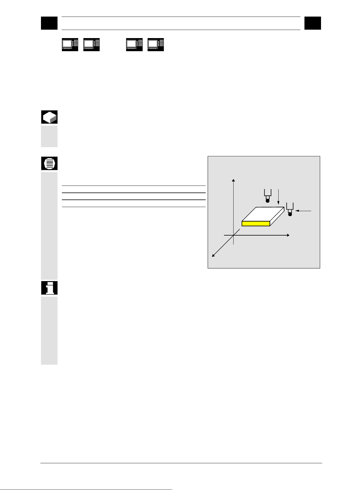
12.97 Description of Parameters
2
2.3 Description of the most important defining parameters
840 D
NCU 571
840 D
NCU 572
NCU 573
810 D 840Di
2.3.2 Number of measuring axis: _MA
Function
2
The axis number (1...3) for the measuring axis in the
coordinate system must be specified via _MA (not the
hardware axis number).
Parameters
Values of _MA
G17 plane
Measuring axis abscissa _MA = 1
Measuring axis ordinate _MA = 2
Measuring axis applicate _MA = 3
Z
_MA must be defined with offset axis /measuring axis
for certain measurement variants; in such cases, the
first two digits contain the code for the offset axis and
the second two digits the code for the measuring axis.
Example:
_MA = 102
Þ Offset axis: 1 (abscissa)
Þ Measuring axis: 2 (ordinate)
Axis definition in acc. to DIN 66217
Y
_MA=2
_MA=1
X
Siemens AG, 2002. All rights reserved
SINUMERIK 840D/840Di/810D User's Guide Measuring Cycles (BNM) – 11.02 Edition 2-61
Page 62

Description of Parameters 12.97
p
2
2.3 Descri
840 D
NCU 571
2.3.3 Tool number and tool name: _TNUM and _TNAME
Function
840 D
NCU 572
NCU 573
tion of the most important defining parameters
810 D 840Di
08.99
2
The tool to be offset is entered during workpiece
measurement in the parameters _TNUM and _TNAME.
The parameter _TNAME is only relevant if tool
management is active.
Parameters
The parameter _TNUM contains the tool number of the
tool to be automatically offset during workpiece
measurement.
If tool management is active, the name of the tool can
be entered in parameter _TNAME as an alternative.
Example:
• without tool management:
_TNUM = 12
_TNAME = " " Þ is not assigned;
• with tool management:
_TNUM = 0 _TNAME = "DRILL"
Þ the tool with the name
"DRILL" is offset
or
_TNUM = 13 _TNAME = " " or _TNAME="DRILL"
Þ the tool with the internal
T number 13 is offset
In SW 4 and higher with spare tools the one is offset
which was last used (was in the spindle).
However, the requirement is that only one tool in a group
is "active" at on time. Otherwise, the internal tool number
of the tool used must be determined and assigned to
_TNUM when machining via the system variable
$P_TOOLNO.
2-62 SINUMERIK 840D/840Di/810D User's Guide Measuring Cycles (BNM) – 11.02 Edition
Siemens AG, 2002. All rights reserved
Page 63

12.97 Description of Parameters
11.02
2
2.3 Description of the most important defining parameters
840 D
NCU 571
840 D
NCU 572
NCU 573
2.3.4 Offset number _KNUM
Parameters
The parameter _KNUM contains the tool offset memory number for
workpiece measurement or the specification of the zero offset to be
compensated for ZO calculation.
_KNUM setting values
_KNUM can accept integers with up to 6 digits, or 8 digits with flat D
number structures. These digits have the following significance:
1. Specification for tool offset:
Structure of tool offset parameter _KNUM
2
810 D 840Di
654321
D number
Currently not assigned, i. e. = 0
0/1...Length compensation
2...Radius compensation
Normal/inverted offset
0...Normal
1...Inverted
Offset acc. to 4th digit
1...Offset of L1
2...Offset of L2
3...Offset of L3
4...Radius compensation
In SW 5 and higher the last 3 digits are evaluated as a D
number for a value of this MD from 10...999
depending on MD 18102: MM_TYPE_OF_CUTTING_EDGE =
0 and MD 18105: MM_MAX_CUTTING_EDGE_NO. If the
value is ≥1000, _KNUM is evaluated as for a flat D number
structure.
Example:
_KNUM = 12003
Þ D3 is corrected,
Þ calculated as radius offset
Þ inverted correction
Siemens AG, 2002. All rights reserved
SINUMERIK 840D/840Di/810D User's Guide Measuring Cycles (BNM) – 11.02 Edition 2-63
Page 64

Description of Parameters 12.97
p
2
2.3 Descri
840 D
NCU 571
2. Specification for zero offset:
840 D
NCU 572
NCU 573
_KNUM=1 ... 99 Automatic inclusion of ZO in ZO G54 ... G57 and
G505...G599
In measuring cycle SW 4.4 and higher:
_KNUM=1000 automatic ZO in basic frame G500 (offset always in
the last channel-specific basic frame if there are more than one).
In measuring cycle SW 6.2 and higher:
- KNUM=1011...1026 automatic ZO in
1st to 16th basic frame (channel) ($P_CHBFR[0]...$P_CHBFR[15])
- KNUM=1051...1066 automatic ZO in
1st to 16th basic frame (global) ($P_NCBFR[0]...$P_NCBFR[15])
Note: The remaining active frame chain must be retained. With
NCU-global frames, correction for rotation is not possible.
- _KNUM=2000 automatic ZO in the system frame
(scratch system frame $P_SETFR)
- _KNUM=9999 automatic ZO in the active frame:
settable frame G54...G57, G505...G599, or G500 in the
last active basic frame according to $P_CHBFRMASK
(most significant bit).
Note: Only here does a changed frame become active in the
tion of the most important defining parameters
810 D 840Di
cycle immediately, otherwise it is activated by the user
writing G500, G54...G5xy.
11.02
2
The following must be set for start-up:
MD 28082: MM_SYSTEM_FRAME_MASK, Bit 0=1 and
Bit 5=1 (system frames for scratching and cycles)
With a _KNUM setting of 0, the automatic tool offset and ZO are
deactivated.
In measuring cycle SW 6.2 and higher, CYCLE115 is introduced for
the ZO. CYCLE114 is only responsible for the tool offset.
If a fine offset is active (MD 18600: MM_FRAME_FINE_TRANS), the
additive ZO will be implemented in it (all measuring cycles with ZO
except CYCLE961), otherwise it is implemented in the coarse offset.
ZO with CYCLE961 is always in the coarse offset and any fine offset
there may be is reset.
2-64 SINUMERIK 840D/840Di/810D User's Guide Measuring Cycles (BNM) – 11.02 Edition
Siemens AG, 2002. All rights reserved
Page 65

12.97 Description of Parameters
09.01
2
2.3 Description of the most important defining parameters
2
840 D
NCU 571
840 D
NCU 572
NCU 573
810 D
2.3.5 Offset number _KNUM with flat D number structure
Parameters
The flat D number functionality is implemented in SW 4
and higher. Which type of D number management is
valid is defined in MD 18102:
MM_TYPE_OF_CUTTING_EDGE.
References: /FB/, W1, "Tool offset"
MD 18102:
0: as previously (default setting)
1: flat D number direct programming
With activation of flat D numbers, a five-digit
D number is assumed in _KNUM.
876543
21
D number
0/1...Length compensation
2...Radius compensation
Normal / inverted offset
0...Normal
1...Inverted
Offset acc. to 6th digit
1...Offset of L1
2...Offset of L2
3...Offset of L3
4...Radius compensation
Siemens AG, 2002. All rights reserved
SINUMERIK 840D/840Di/810D User's Guide Measuring Cycles (BNM) – 11.02 Edition 2-65
Page 66

Description of Parameters 12.97
p
2
2.3 Descri
840 D
NCU 571
840 D
NCU 572
NCU 573
tion of the most important defining parameters
810 D 840Di
2.3.6 Variable measuring speed: _VMS
Parameters
The measuring speed can be freely selected by means
_VMS. It is specified in mm/min or inch/min
of
depending on the basic system.
The maximum measuring speed must be selected such
that safe deceleration within the probe deflecting path is
ensured.
12.98
2
When _VMS = 0, then the feedrate is preset as
standard to 150 mm
increased to 300 mm
(_FA > 1 ) is altered via _FA.
If the basic system is in inches, 5.9055 inch/min or
11.811 inch/min takes effect.
/min. This value is automatically
/min if the measuring path a
2.3.7 Compensation angle position for monodirectional probe: _CORA
Function
When using a monodirectional probe, it may be
necessary for machine-specific reasons (e.g.
horizontal
probe to be able to carry out the measurement.
/vertical millhead) to correct the position of the
Parameters
The incorrect position can be corrected by means of
parameter
to 90° or a multiple thereof. If the direction of rotation is
altered as a result of swiveling the milling head, then
_CORA must be preset to –360° (normally 0°).
_CORA. Generally speaking, _CORA is set
2-66 SINUMERIK 840D/840Di/810D User's Guide Measuring Cycles (BNM) – 11.02 Edition
Siemens AG, 2002. All rights reserved
Page 67

12.97 Description of Parameters
2
2.3 Description of the most important defining parameters
2
840 D
NCU 571
840 D
NCU 572
NCU 573
810 D 840Di
2.3.8 Tolerance parameters: _TZL, _TMV, _TUL, _TLL, _TDIF and _TSA
Some information about the tolerance parameters
applied in conjunction with measuring cycles is already
given in Section 1.8.
Parameters
These parameters contain the following variables:
_TZL
_TMV
_TUL/_TLL
_TDIF
_TSA
Zero offset
Average-value generation with compensation
Workpiece tolerance
Dimension difference check
Safe area
1) for workpiece measurement with automatic
tool offset only
2) also for tool measurement
1)2)
1)
1)
1)2)
Value range
All of these parameters are capable of assuming any
value. However, only values increasing from _TZL to
_TSA are meaningful. Parameters _TUL/_TLL are
specified in mm or inches depending on the active
dimension system. All other parameters are
programmed in the basic system.
Siemens AG, 2002. All rights reserved
SINUMERIK 840D/840Di/810D User's Guide Measuring Cycles (BNM) – 11.02 Edition 2-67
Page 68

Description of Parameters 12.97
p
2
2.3 Descri
tion of the most important defining parameters
840 D
NCU 571
840 D
NCU 572
NCU 573
810 D 840Di
2.3.9 Multiplication factor for measurement path 2a: _FA
Parameters
Path increment a is 1 mm irrespective of the dimension
system, but can be increased with parameter
the measuring cycles are called and defines the
distance from the expected position at which the probe
is triggered.
The maximum value for _FA is calculated as follows:
_FA
Axis traversing path
=
max
2
max
The measuring cycles automatically generate a
measurement path of 2
a · _FA, which is traversed at
_FA when
10.00
2
the measuring feedrate, i.e. at a distance of
a · _FA in
front of the specified setpoint position at which the
probe is actuated under ideal conditions, up to
a · _FA after the anticipated setpoint position.
If the probe is triggered during this measurement path
the movement is aborted with delete distance-to-go.
Example:_FA=5
à Irrespective of the system of units, a measurement
path of 10 mm is generated, starting at 5 mm before
and ending 5 mm after the specified setpoint
position.
2-68 SINUMERIK 840D/840Di/810D User's Guide Measuring Cycles (BNM) – 11.02 Edition
Siemens AG, 2002. All rights reserved
Page 69

12.97 Description of Parameters
08.99
2
2.3 Description of the most important defining parameters
2
840 D
NCU 571
840 D
NCU 572
NCU 573
810 D 840Di
2.3.10 Probe type/Probe number: _PRNUM
Function
The data relating to the workpiece probes are stored in
GUD field
the tool probes are stored in GUD field
probe
The data fields _WP and _TP are configured by the
machine manufacturer during start-up.
_PRNUM specifies the number of the selected data
field within these fields and the probe type.
_WP Workpiece probe, the data relating to
_TP Tool
.
Parameters
Values of _PRNUM
PRNUM can assume integers of three digits. In this
case, the first digit represents the probe type, i.e.
• 0 = Multidirectional probe
• 1 = Monodirectional probe.
The other two digits contain the code for the probe
number.
Digit Meaning
- - Probe number (two digits)
0 Multiprobe probe
1 Mono probe
3 2 1
Example of workpiece measurement:
_PRNUM = 102
Further notes
Þ Probe type: Monodirectional
Þ Data field number: 2
probe
Siemens AG, 2002. All rights reserved
SINUMERIK 840D/840Di/810D User's Guide Measuring Cycles (BNM) – 11.02 Edition 2-69
The associated field index in _WP = 1, i. e. the data of
the _WP[1,0...9] field are considered by the measuring
cycle in the calculation of the measuring results.
Page 70

Description of Parameters 12.97
p
2
2.3 Descri
840 D
NCU 571
2.3.11 Empirical value/mean value: _EVNUM
Function
840 D
NCU 572
NCU 573
tion of the most important defining parameters
810 D 840Di
12.98
2
The empirical values are used to suppress dimensional
deviations that are
The empirical and mean values themselves are stored
in GUD fields
values
_EVNUM specifies the number of the empirical value
memory. The number of the mean value memory is
defined at the same time via _EVNUM. The number of
empirical and mean values is specified in the GUD field
_EVMVNUM. The unit of measurement is mm in the
metric basic system and inch in the inch basic system,
irrespective of the active system of units.
Parameters
Values of _EVNUM
The following values can be set:
• = 0 Without empirical value, without mean value
• > 0 Empirical value memory number = mean
If _EVNUM is defined as < 9999, the first 4 digits of
_EVNUM are interpreted as the mean value memory
number and the second 4 digits as the empirical value
memory number.
Example:
_EVNUM = 90012
.
memory
value memory number
not subject to a trend.
_EV Empirical value and _MV Mean
Further notes
2-70 SINUMERIK 840D/840Di/810D User's Guide Measuring Cycles (BNM) – 11.02 Edition
The corresponding field index in field _EV = 11 and in
field _MV = 8.
Þ EV memory: 12
Þ MV memory: 9
Siemens AG, 2002. All rights reserved
Page 71

12.97 Description of Parameters
2
2.3 Description of the most important defining parameters
2
840 D
NCU 571
840 D
NCU 572
NCU 573
810 D 840Di
2.3.12 Multiple measurement at the same location: _NMSP
Parameters
Parameter _NMSP can be used to determine the
number of measurements at the same location.
The actual/setpoint value difference D is determined
arithmetically.
SS S
D
=
n...number of measurements
...
++
12
n
n
2.3.13 Weighting factor k for averaging: _K
Function
A detailed description is given in Section 1.7 "Measuring
The weighting factor k can be applied to allow different
weighting to be given to an individual measurement.
A new measurement result thus has only a limited effect
on the new tool offset as a function of _K.
strategy and compensation value definition".
Siemens AG, 2002. All rights reserved
SINUMERIK 840D/840Di/810D User's Guide Measuring Cycles (BNM) – 11.02 Edition 2-71
Page 72

p
Description of Parameters 12.97
2
2.4. Descri
840 D
NCU 571
2.4. Description of output parameters
Function
840 D
NCU 572
NCU 573
tion of output parameters
810 D 840Di
2
2.4.1 Measuring cycle results in _OVR
In the same way as their defining parameters, the
measuring cycle results are Global User Data of the
module GUD5.
In this case, the results are not stored as individual
data, but in two fields of the
INTEGER (_OVI) types.
Function
The field _OVR[32] contains the following values:
• Setpoints and actual values for abscissa, ordinate
and applicate
• Lower and upper tolerance limits for the three axes
• Setpoint/actual value differences in abscissa,
ordinate and applicate
• Safe area
• Dimensional difference
• Empirical value.
The results are described individually with the relevant
measuring cycles or measurement variants.
REAL (_OVR) and
2-72 SINUMERIK 840D/840Di/810D User's Guide Measuring Cycles (BNM) – 11.02 Edition
Siemens AG, 2002. All rights reserved
Page 73

12.97 Description of Parameters
05.98
2
2.4. Description of output parameters
2
840 D
NCU 571
2.4.2 Measuring cycle results in _OVI
Function
The field _OVI[10] contains the following values:
• D or ZO number
• Machining plane
• Measuring cycle number
• Measurement variants
• Weighting factor
• Probe number
• Mean value memory number
• Empirical value memory number
• Tool number
• Alarm number.
840 D
NCU 572
NCU 573
810 D 840Di
The results are described individually with the
measuring cycles.
n
Siemens AG, 2002. All rights reserved
SINUMERIK 840D/840Di/810D User's Guide Measuring Cycles (BNM) – 11.02 Edition 2-73
Page 74

2
p
Notes
Description of Parameters 12.97
2.4. Descri
840 D
NCU 571
840 D
NCU 572
NCU 573
tion of output parameters
810 D 840Di
2
2-74 SINUMERIK 840D/840Di/810D User's Guide Measuring Cycles (BNM) – 11.02 Edition
Siemens AG, 2002. All rights reserved
Page 75

12.97 Measuring Cycle Auxiliary Programs
3
Measuring Cycle Auxiliary Programs
3.1 Package structure of measuring cycles .......................................................................... 3-76
3.2 Measuring cycle subroutines........................................................................................... 3-77
3.2.1 CYCLE103: Parameter definition for measuring cycles........................................... 3-78
3.2.2 CYCLE116: Calculation of center point and radius of a circle ................................. 3-79
3.3 Measuring cycle user programs ...................................................................................... 3-81
3.3.1 CYCLE198: User program prior to calling measuring cycle..................................... 3-81
3.3.2 CYCLE199: User program at the end of a measuring cycle .................................... 3-82
3.4 Subpackages ..................................................................................................................3-83
3
Siemens AG, 2002. All rights reserved
SINUMERIK 840D/840Di/810D User's Guide Measuring Cycles (BNM) – 11.02 Edition 3-75
Page 76

Measuring Cycle Auxiliary Programs 12.97
3
3.1 Package structure of measuring cycles
3
840 D
NCU 571
840 D
NCU 572
NCU 573
FM-NC 810 D 840Di
3.1 Package structure of measuring cycles
The machine data configuration and the software
package version determine which programs can be
used. It is also possible to partially define these
programs in the global cycle data during start-up.
(Please refer to data supplied by the machine
manufacturer and Installation and Start-up Guide.)
Function
The measuring cycle package supplied consists of:
• Data blocks for defining the global measuring cycle
data,
• measuring cycles,
• measuring cycle subroutines and
• easy-to-use functions.
To ensure that the measuring cycles can be executed in
the control, the data blocks must have been loaded into
directory "Definitions" and the measuring cycles and
measuring cycle subroutines must be stored in the part
program memory.
Please note that the control always requires a Power
ON between loading and execution of the measuring
cycles!
3-76 SINUMERIK 840D/840Di/810D User's Guide Measuring Cycles (BNM) – 11.02 Edition
Siemens AG, 2002. All rights reserved
Page 77

12.97 Measuring Cycle Auxiliary Programs
11.02
3
3.2 Measuring cycle subroutines
3
840 D
NCU 571
840 D
NCU 572
NCU 573
FM-NC 810 D 840Di
3.2 Measuring cycle subroutines
Function
These measuring cycle subroutines are called directly
by the cycles. With the exception of CYCLE116, these
subroutines cannot be executed through a direct call.
Programming
Cycle
CYCLE100
CYCLE101
CYCLE102
CYCLE103
CYCLE104
CYCLE105
CYCLE106
CYCLE107
CYCLE108
CYCLE109
CYCLE110
CYCLE111
CYCLE112
CYCLE113
CYCLE114
CYCLE115
CYCLE116
Function As from
Activate logging X
Deactivate logging X
Measured result display
Parameter setting in interactive mode
Internal subroutine: measuring cycle interface
Internal subroutine: logging X
Internal subroutine: logging X
Output of measuring cycle messages
Output of measuring cycle alarms
Internal subroutine: data transfer X
Internal subroutine: plausibility checks
Internal subroutine: measuring functions
Internal subroutine: measuring functions
Internal subroutine: logging X
Internal subroutine: load ZO memory,
load WCS wear
Internal subroutine: Load WCS wear X
Internal subroutine: Load ZO memory X
Calculation of the center point and radius on a circle
SW 4
As from
SW 4.5
In SW 6.2
and higher
CYCLE117
CYCLE118
Siemens AG, 2002. All rights reserved
SINUMERIK 840D/840Di/810D User's Guide Measuring Cycles (BNM) – 11.02 Edition 3-77
Internal subroutine: measuring functions
Internal subroutine: logging X
Page 78

Measuring Cycle Auxiliary Programs 12.97
3
3.2 Measuring cycle subroutines
3
840 D
NCU 571
840 D
NCU 572
NCU 573
FM-NC 810 D 840Di
3.2.1 CYCLE103: Parameter definition for measuring cycles
Explanation
This auxiliary cycle controls an input dialog for assigning
parameters for the measuring cycles.
It can be either directly selected and started or written in
the program before the actual measuring cycle is called.
Several input screen forms are displayed one after the
other during the course of this dialog. After entering the
values, each display must be concluded with the OK
key.
The input values for selecting the measuring cycle and
the measurement variant are checked for plausibility.
As of measuring cycles SW 4.5, CYCLE103 is no
longer supported or developed further. Instead, use the
cycle support for measuring cycles to supply the
parameter data. Please refer to Chapter 7.2 for a
detailed description.
Programming
CYCLE103
Programming example
Calibrate tool probe
CALIBRATION_IN_X_Y
N10 G54 G17 G0 X100 Y80
N15 T9 D1 Z10
N20 CYCLE103
N25 CYCLE976
N50 M30
Position probe at the center of the hole and
select ZO
Select tool length compensation,
position probe in the hole
The operator can assign the parameters for
calibration cycle CYCLE976 in interactive
mode
Measuring cycle call for calibr. in X-Y plane
End of program
3-78 SINUMERIK 840D/840Di/810D User's Guide Measuring Cycles (BNM) – 11.02 Edition
Siemens AG, 2002. All rights reserved
Page 79
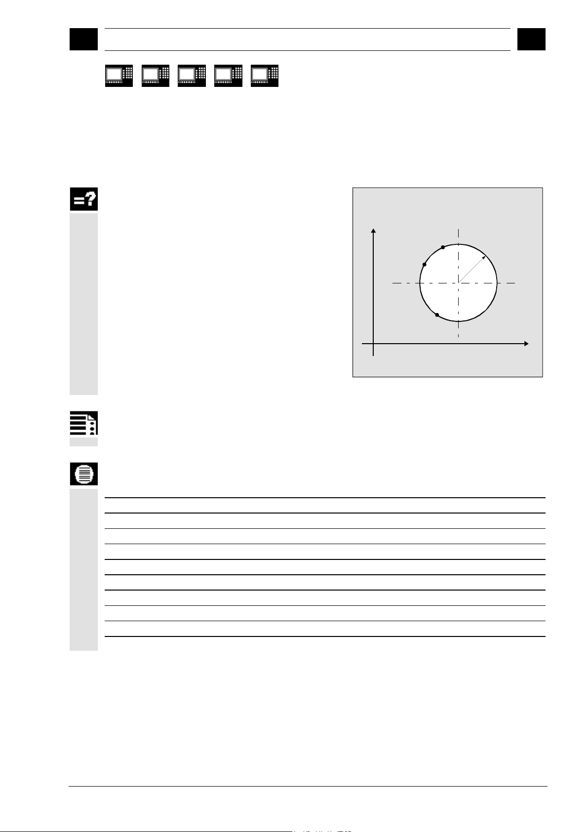
12.97 Measuring Cycle Auxiliary Programs
06.00
3
3.2 Measuring cycle subroutines
3
840 D
NCU 571
840 D
NCU 572
NCU 573
FM-NC 810 D 840Di
3.2.2 CYCLE116: Calculation of center point and radius of a circle
Explanation
This cycle calculates from three or four points
positioned on one plane the circle they inscribe with
center point and radius.
To allow this cycle to be used as universally as
possible, its data are transferred via a parameter list.
A field of REAL variables of length 13 must be
transferred as the parameter.
Calculation of circle data from 3 points
Y
P1
P2
Radius
CP
P3
X
Programming
CYCLE116 (_DATE, _ALM)
Parameters
Input data
_DATE [0]
_DATE [1]
_DATE [2]
_DATE [3]
_DATE [4]
_DATE [5]
_DATE [6]
_DATE [7]
_DATE [8]
Number of points for calculation (3 or 4)
Abscissa of first point
Ordinate of first point
Abscissa of second point
Ordinate of second point
Abscissa of third point
Ordinate of third point
Abscissa of fourth point
Ordinate of fourth point
Siemens AG, 2002. All rights reserved
SINUMERIK 840D/840Di/810D User's Guide Measuring Cycles (BNM) – 11.02 Edition 3-79
Page 80

Measuring Cycle Auxiliary Programs 12.97
3
3.2 Measuring cycle subroutines
3
840 D
NCU 571
Output data
The results of the calculation are stored in the last four
elements of the same field:
_DATE [9]
_DATE [10]
_DATE [11]
_DATE [12]
_ALM
This cycle is called as a subroutine by measuring cycle
CYCLE979.
Example:
Circle.MPF
DEF INT _ALM
DEF REAL _DATE[13]= (3,0,10,-10,0,0,-10,
0,0,0,0,0,0)
CYCLE116(_DATE, _ALM)
M0
STOPRE
M30
840 D
NCU 572
NCU 573
FM-NC 810 D 840Di
Abscissa of circle center point
Ordinate of circle center point
Circle radius
Status for calculation
0 Calculation in progress
1 Error occurred
Error number ( 61316 or 61317 possible)
; 3 points specified P1:0,10
P2: -10,0
P3: 0,-10
; Result _DATE[9]=0
_DATE[10]=0
_DATE[11]=10
_DATE[12]=0
_ALM=0
3-80 SINUMERIK 840D/840Di/810D User's Guide Measuring Cycles (BNM) – 11.02 Edition
Siemens AG, 2002. All rights reserved
Page 81

12.97 Measuring Cycle Auxiliary Programs
09.01
3
3.3 Measuring cycle user programs
3
840 D
NCU 571
840 D
NCU 572
NCU 573
FM-NC 810 D 840Di
3.3 Measuring cycle user programs
Function
These measuring cycle user programs are called
directly by the measuring cycles and can be used to
program necessary adaptations before or after a
measurement.
3.3.1 CYCLE198: User program prior to calling measuring cycle
Explanation
This cycle is called at the start of each measuring cycle.
It can be used to program necessary adaptations prior
to starting measurement (e. g. activate probe, position
spindle).
As delivered, this cycle contains only one CASE
instruction for a jump to a marker that corresponds to
the measuring cycle called, followed by command M17.
e. g.: _M977: prior to call CYCLE977
M17 End of cycle
The user can program the necessary machine
adaptations here.
Siemens AG, 2002. All rights reserved
SINUMERIK 840D/840Di/810D User's Guide Measuring Cycles (BNM) – 11.02 Edition 3-81
Page 82

Measuring Cycle Auxiliary Programs 12.97
3
3.3 Measuring cycle user programs
09.01
3
840 D
NCU 571
840 D
NCU 572
NCU 573
FM-NC 810 D 840Di
3.3.2 CYCLE199: User program at the end of a measuring cycle
Explanation
This cycle is called at the end of each measuring cycle.
It can be used to program necessary actions following
completion of a measurement (e. g. deactivate probe).
As delivered, this cycle (just like CYCLE198) contains
only one CASE instruction for a jump to a marker that
corresponds to the measuring cycle called, followed by
command M17.
e. g.: _M971: at the end of the CYCLE971
M17 End of cycle
The user can program the necessary machine
adaptations here.
3-82 SINUMERIK 840D/840Di/810D User's Guide Measuring Cycles (BNM) – 11.02 Edition
Siemens AG, 2002. All rights reserved
Page 83

12.97 Measuring Cycle Auxiliary Programs
09.01
3
3.4 Subpackages
3
840 D
NCU 571
840 D
NCU 572
NCU 573
3.4 Subpackages
Explanation
In many application cases not all the measuring cycles
are used on one machine, instead part packages are
used.
The following overview shows which part packages are
advisable and executable. This allows you to save
memory capacity.
Milling measuring cycles
Calibrate tool
probe +
measure tool
CYCLE971
CYCLE107
CYCLE108
CYCLE109
CYCLE110
CYCLE111
CYCLE198
CYCLE199
Turning measuring cycles
Measure tool +
calibrate tool probe
FM-NC 810 D 840Di
Basic package
Calibrate workpiece
probe + measure tool +
write ZO or TC
CYCLE961
CYCLE976
CYCLE977
CYCLE978
CYCLE979
CYCLE998
Basic package
Calibrate workpiece
probe + measure
workpiece + write ZO
or TC
CYCLE107
CYCLE108
CYCLE109
CYCLE110
CYCLE111
CYCLE112
CYCLE114
CYCLE116
CYCLE198
CYCLE199
Additional package
Measuring at milling machine in JOG mode
Semi-automatic
calibration of tool probe +
measure tool
E_MS_CAL
E_MS_CAN
E_MS_HOL
Additional package
Operator interface
Measurement result
display selection
Activation: _CHBIT[10]=1
CYCLE102
CYCLE104
Input dialog
Activation:
CYCLE103
CYCLE104
E_MS_PIN
E_MT_CAL
E_MT_LEN
E_MT_RAD
Call in user
NC program
Semi-automatic
calibration of tool probe,
calculation and setting of
reference points
CYC_JM
CYC_JMC
Additional package
Operator interface
Log in a file of the part
program memory
Precondition:
SW 4.3 in NCK
++
Activation: CYCLE100
CYCLE100
CYCLE101
CYCLE105
CYCLE106
CYCLE113
CYCLE118
CYCLE972
CYCLE982
CYCLE107
CYCLE108
CYCLE109
CYCLE110
CYCLE111
CYCLE198
CYCLE199
Siemens AG, 2002. All rights reserved
SINUMERIK 840D/840Di/810D User's Guide Measuring Cycles (BNM) – 11.02 Edition 3-83
CYCLE973
CYCLE974
CYCLE994
CYCLE107
CYCLE108
CYCLE109
CYCLE110
CYCLE111
CYCLE114
CYCLE117
CYCLE198
CYCLE199
Page 84

Measuring Cycle Auxiliary Programs 12.97
3
3.4 Subpackages
3
Notes
840 D
NCU 571
840 D
NCU 572
NCU 573
FM-NC 810 D 840Di
3-84 SINUMERIK 840D/840Di/810D User's Guide Measuring Cycles (BNM) – 11.02 Edition
Siemens AG, 2002. All rights reserved
Page 85

06.00 Measuring in JOG
4
Measuring in JOG
4.1 General preconditions ............................................................................................... 4-86
4.2 Workpiece measurement .......................................................................................... 4-89
4.2.1 Operation and function sequence of workpiece measurement ................................ 4-90
4.2.2 Measuring an edge ................................................................................................... 4-91
4.2.3 Measuring a corner ................................................................................................... 4-92
4.2.4 Measuring a hole....................................................................................................... 4-94
4.2.5 Measuring a spigot.................................................................................................... 4-95
4.2.6 Calibrating the measuring probe ............................................................................... 4-96
4.3 Tool measurement .................................................................................................... 4-99
4.3.1 Operation and function sequence of tool measurement ........................................... 4-99
4.3.2 Tool measurement .................................................................................................... 4-99
4.3.3 Calibrating the tool measuring probe ...................................................................... 4-101
4
Siemens AG, 2002. All rights reserved
SINUMERIK 840D/840Di/810D User's Guide Measuring Cycles (BNM) – 11.02 Edition 4-85
Page 86

Measuring in JOG 06.00
4
4.1 General preconditions
09.01
4
840 D
NCU 572
NCU 573
4.1 General preconditions
Certain preconditions must be fulfilled before
measuring in JOG can be used.
These conditions are described in greater detail in Part
2 Description of Functions (from Chapter 8 onwards).
The following checklist is useful in determining
whether all such preconditions are fulfilled:
Machine
• All machine axes are designed in accordance
with DIN 66217.
• A touch-trigger probe (3D) is provided for acquiring
workpiece dimensions, and a touch-trigger tool
probe for acquiring tool dimensions.
(see also Section 1.4 Suitable probe types)
• The reference points have been approached.
810D 840Di
Control
• 840D as of NCU 572 with SW 5.3 and higher,
810D SW 3.3 and higher
MMC103 SW 5.3 and higher
Machine data for running machine cycles:
• All machine data listed in Section 10.1 meet the
minimum requirements for running measuring
cycles.
Machine data for measuring in JOG
• Machine data
– MD 11602: ASUB_START_MASK
– MD 11604: ASUB_START_PRIO_LEVEL
– MD 20110: RESET_MODE_MASK
– MD 20112: START_MODE_MASK
are set as specified in the detailed function
description (see Subsection 10.3.1).
Notice: Interrupt number 8 is used to start the
ASUBs for measuring in JOG and must therefore
not be used by the user.
4-86 SINUMERIK 840D/840Di/810D User's Guide Measuring Cycles (BNM) – 11.02 Edition
Siemens AG, 2002. All rights reserved
Page 87

06.00 Measuring in JOG
4
Availability of measuring cycles
• The data blocks:
GUD5.DEF and
GUD6.DEF
in directory DEFINE on diskette 1 have been loaded
in the control (directory "Definitions" in the file
system) and
• the measuring cycles in directory CYCLES on
diskette 1 have been loaded into the standard cycle
directory of the control and then a power-on
executed.
Availability of JOG measuring files
• All files in directory JOG_MESS on diskette 2 have
been loaded into the control via "Data in" and a
power-on then executed.
Adaptation of data block GUD7.DEF:
Data block GUD7.DEF has been adapted to the
requirements of measuring in JOG as specified in the
detailed function description (see Subsection 10.3.1).
4.1 General preconditions
4
Function
MEASURING IN JOG comprises the following functions:
• Semi-automatic calculation of tool lengths and storage in tool offset
memory.
• Semi-automatic calculation and setting of reference points and storage
in zero offset memory.
The functions are operated with softkeys and input displays. The
measuring operation is canceled with RESET.
Notice
Make sure that you select the correct channel, as the function
MEASURING IN JOG operates channel dependently. Selecting the wrong
channel when the measuring operation is active could destroy the
measuring probe.
The measuring function is selected via the softkey bar in the JOG basic
display.
Siemens AG, 2002. All rights reserved
SINUMERIK 840D/840Di/810D User's Guide Measuring Cycles (BNM) – 11.02 Edition 4-87
Page 88

Measuring in JOG 06.00
4
4.1 General preconditions
4
840 D
NCU 572
NCU 573
810D 840Di
Measure
workpiece
For calculating and setting reference points.
Measure
tool
For measuring milling and drilling tools.
4-88 SINUMERIK 840D/840Di/810D User's Guide Measuring Cycles (BNM) – 11.02 Edition
Siemens AG, 2002. All rights reserved
Page 89

06.00 Measuring in JOG
09.01
4
4.2 Workpiece measurement
4
840 D
NCU 572
NCU 573
810D 840Di
4.2 Workpiece measurement
Function
With this function you can set reference points on
the workpiece using a workpiece probe on the
machine.
You call a measuring cycle to set up a workpiece that is
clamped on the table. This measuring cycle
automatically generates the measurement paths and
intermediate positions as a function of the specified
setpoints. While the measuring cycle is running, the
basic offset defined via GUD6 or a settable ZO, as well
as a further working plane G17...G19 set in GUD6 data
are effective. The GUD6 data also specifies which data
field is assigned to the measuring probe in the spindle
and the measuring probe type (multiprobe or
monoprobe) (the parameters for switching behavior
found by calibrating the measuring probe are also
stored in this data field).
All the measuring points required for the measurement
task are approached. Prepositioning can either be
performed manually or in a program.
When measurement is complete, the result (corner,
center point of hole/spigot, edge) is automatically
calculated in the measuring cycle according to the type
of measurement, and the reference point is set with
reference to the basic frame or a settable zero offset
according to the selection made by correcting the zero
offset memory in question. If "Off" is selected, no
correction is made.
Precondition
• The workpiece probe is located in the spindle and
has been calibrated.
Siemens AG, 2002. All rights reserved
SINUMERIK 840D/840Di/810D User's Guide Measuring Cycles (BNM) – 11.02 Edition 4-89
Page 90
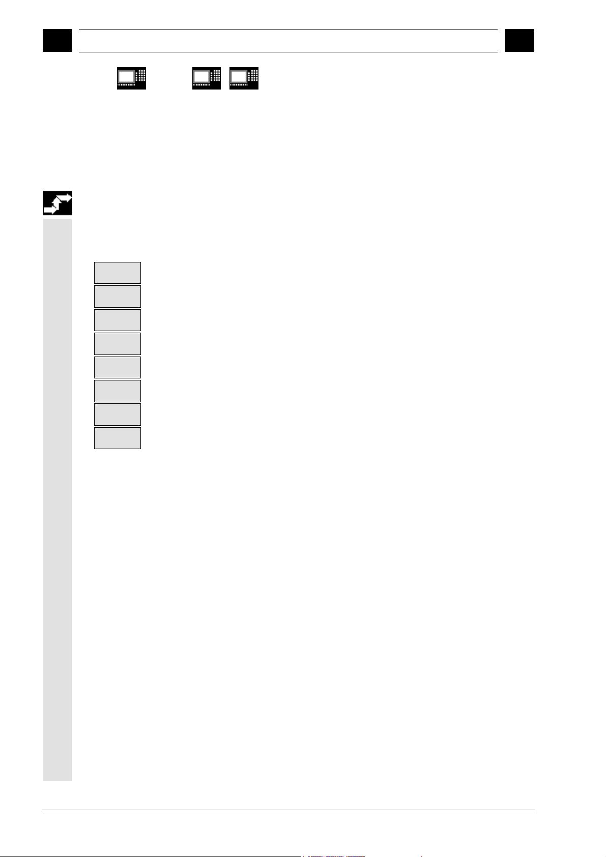
Measuring in JOG 06.00
4
4.2 Workpiece measurement
09.01
4
840 D
NCU 572
NCU 573
810D 840Di
4.2.1 Operation and function sequence of workpiece measurement
Procedure
1. The workpiece is clamped, the probe is positioned in
the spindle and calibrated.
2. When you press softkey "Measure workpiece", the
following softkey bar is displayed for selection:
Edge
>
Corner
>
Hole
>
Spigot
>
Calibrate
probe
<<
back
3.
• Select zero offset to which the defined setpoint position
refers and for which the offset is to apply:
– Basic frame
– Settable zero offset G54...
• Enter setpoints if necessary (e.g. approx. diameter of
hole/spigot).
• Select the setpoint position in the measuring axis (for
edge), the center point (for hole/spigot) or the corner point.
• Select axis and axis direction for edge/corner.
4. On "NC Start", the measuring operation is performed with
a measuring feedrate set in the measuring cycle data
(GUD6).
The measuring probe is triggered. When a corner or edge
is measured, the probe is automatically retracted in rapid
traverse to its starting position for the measuring point in
question. When a hole or spigot is measured, all four
points are automatically scanned one after the other.
The translation offset and also an offset for the rotation
around the infeed axis in relation to the corner defined for
the selected zero offset is determined on the basis of the
measuring results and the specified setpoint position.
When the basic frame is selected, the last channel-specific
basic frame is always taken if more than one is available.
4-90 SINUMERIK 840D/840Di/810D User's Guide Measuring Cycles (BNM) – 11.02 Edition
Siemens AG, 2002. All rights reserved
Page 91
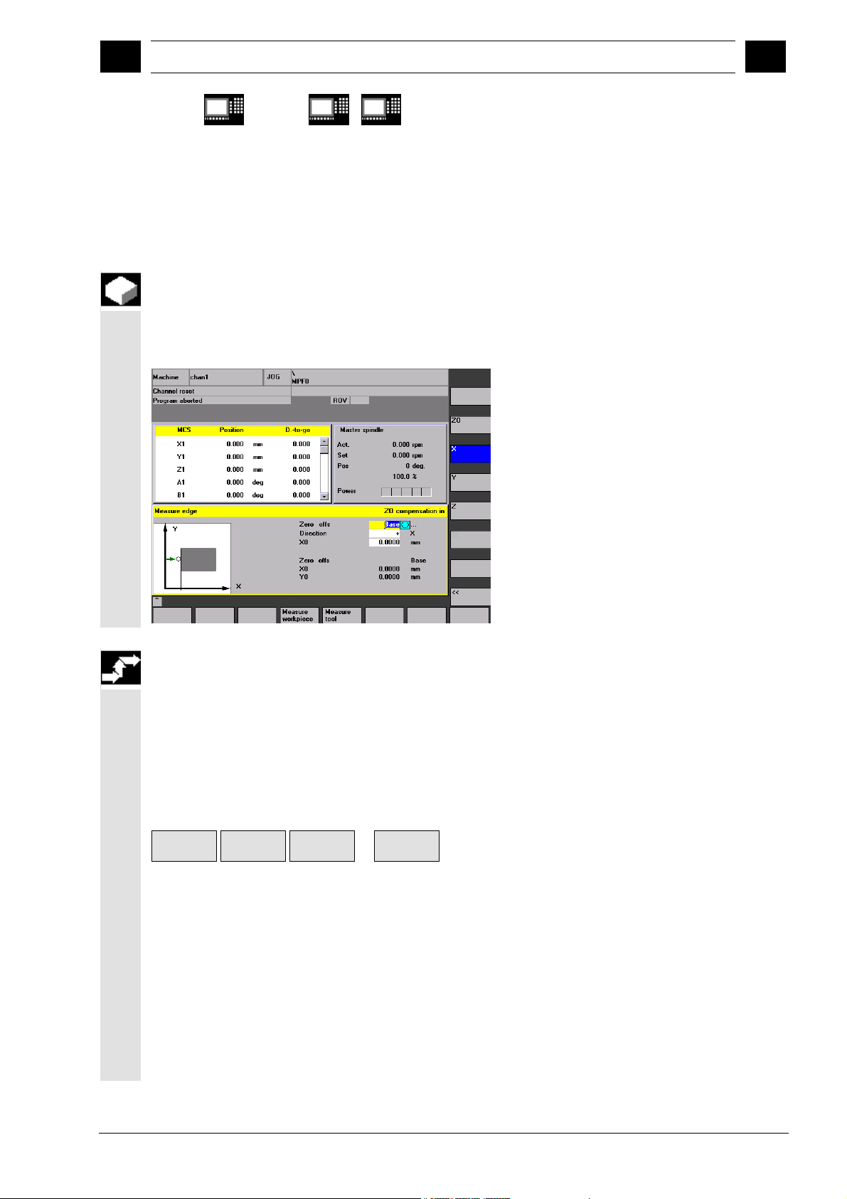
06.00 Measuring in JOG
11.02
4
4.2 Workpiece measurement
4
840 D
NCU 572
NCU 573
4.2.2 Measuring an edge
Function
If "Measure edge" is selected, a reference point can be
set in any axis of the working plane (G17...G19) defined
in a GUD6 data.
810D 840Di
Sequence of operations
Precondition
The measuring probe is located in the spindle and has been
calibrated.
Approach the workpiece
Position the probe in the required axis direction in front of
the workpiece, e.g. in the +X direction.
Select the function with softkey
Measure
workpiece
Enter details in input form
• Select the zero offset to which the specified setpoint
position refers and for which the offset is to apply:
– Basic frame
– or zero offset taken from the list of zero offsets
• Direction: Set the sampling direction of the selected axis
for which the reference point has been set, e.g. +X.
• Enter set position of the reference point (edge).
Set the feedrate override switch to the same value as for
calibration!
Edge
X
Z
...
Siemens AG, 2002. All rights reserved
SINUMERIK 840D/840Di/810D User's Guide Measuring Cycles (BNM) – 11.02 Edition 4-91
Page 92

Measuring in JOG 06.00
4
4.2 Workpiece measurement
11.02
4
840 D
NCU 572
NCU 573
On "NC Start", the measuring operation is automatically
performed with a measuring feedrate set via GUD data.
• The measuring probe is triggered.
• Automatic retraction to starting position in rapid traverse.
• The translation offset for the selected zero offset is
determined on the basis of the measuring results and the
specified setpoint position. On selection of the basic
frame the offset is always implemented in the last
channel-specific basic frame, if there are more than one.
The offset is implemented in the coarse offset and any
fine offset there may be is reset.
4.2.3 Measuring a corner
810D 840Di
Function
With the selection "Corner", the corner of a workpiece can
be measured as the reference point. The probe is positioned
at a selected corner of the workpiece.
Sequence of operations
Precondition
The measuring probe is located in the spindle and has been
calibrated.
Approach the workpiece
Position the probe at a selected corner of the workpiece.
4-92 SINUMERIK 840D/840Di/810D User's Guide Measuring Cycles (BNM) – 11.02 Edition
Siemens AG, 2002. All rights reserved
Page 93
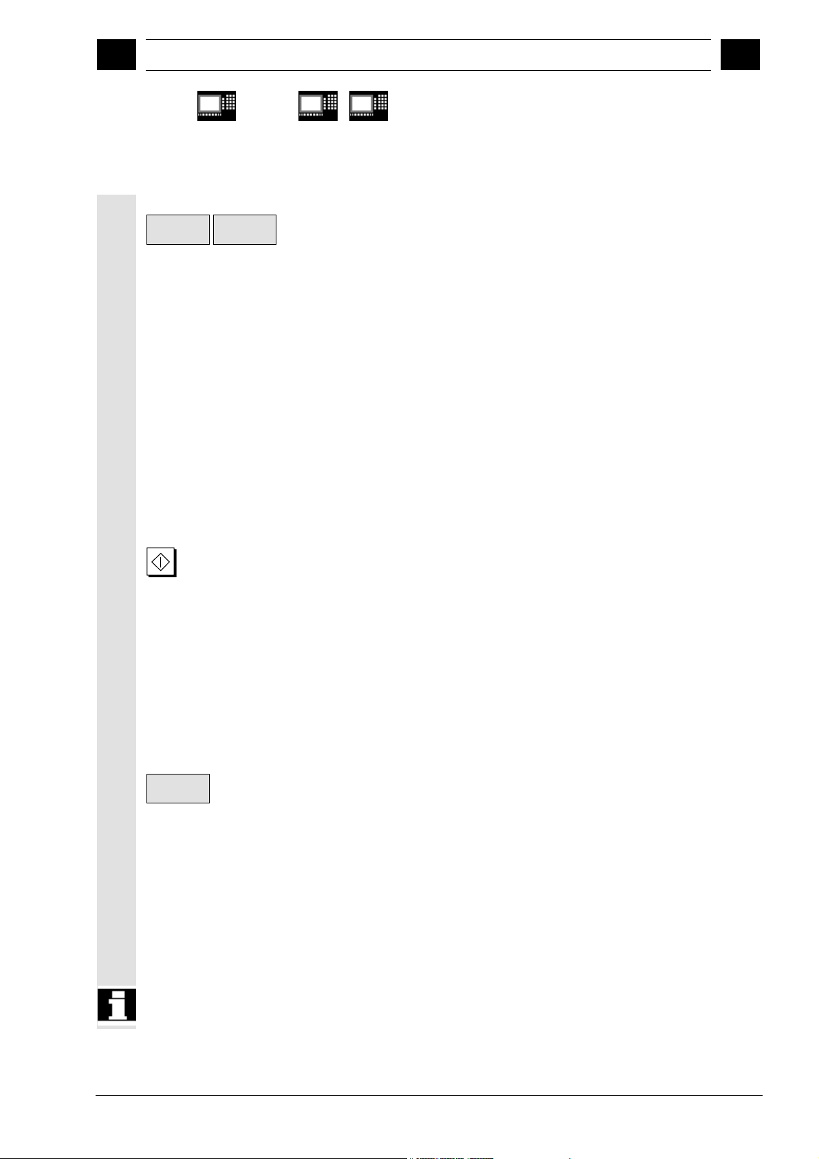
06.00 Measuring in JOG
11.02
4
4.2 Workpiece measurement
4
840 D
NCU 572
NCU 573
810D 840Di
Select the function with softkey
Measure
workpiece
Corner
Enter details in input form
• Select the zero offset to which the specified
setpoint position for the corner refers and for which
the offset is to apply:
– Basic frame
– or zero offset taken from the list of zero offsets
• Position: Set the corner to be used as the reference
point.
• Enter set position of the reference point (corner).
Approach sampling point
Position the probe at the first sampling point P1 of the
workpiece edge.
Set the feedrate override switch to the same value
as for calibration!
On "NC Start", the measuring operation is automatically
performed with a measuring feedrate set via GUD data.
• The measuring probe is triggered.
• Automatic retraction to starting position in rapid
traverse.
Store the position values of sampling point P1 by
pressing softkey "Save P1". Repeat the procedure
"approach sampling points" for sampling points P2...P4 in
the same way.
Calculate
corner
Press softkey "Calculate corner" to calculate the
translation offset and the rotational offset around the
infeed axis for the selected zero offset. On selection of
the basic frame the offset is always implemented in the
last channel-specific basic frame, if there are more than
one. The offset is implemented in the coarse offset and
any fine offset there may be is reset.
• The order in which sampling points P1...P4 are
approached must be maintained.
On a rectangular workpiece, three sampling points are
sufficient for the calculation.
Siemens AG, 2002. All rights reserved
SINUMERIK 840D/840Di/810D User's Guide Measuring Cycles (BNM) – 11.02 Edition 4-93
Page 94
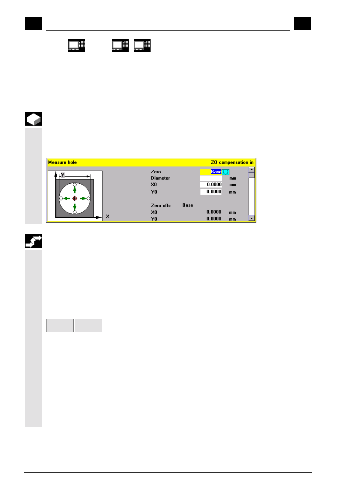
Measuring in JOG 06.00
4
4.2 Workpiece measurement
09.01
4
840 D
NCU 572
NCU 573
4.2.4 Measuring a hole
Function
With "Hole", you can set the center of a hole as the
reference point. The probe is approximately positioned
at the center of the hole and measuring depth.
810D 840Di
Sequence of operations
Precondition
The measuring probe is located in the spindle and has
been calibrated.
Approach the workpiece
Position the probe approximately in the center of the
hole.
Select the function with softkey
Measure
workpiece
Enter details in input form
• Select the zero offset to which the specified setpoint
position for the center of the hole refers and for
which the offset is to apply:
– Basic frame
– or zero offset taken from the list of zero offsets
• Diameter: Enter approximate diameter of the hole.
If no diameter is entered, sampling is started from
the starting point at measurement feedrate.
• Enter set position of the hole center.
Hole
4-94 SINUMERIK 840D/840Di/810D User's Guide Measuring Cycles (BNM) – 11.02 Edition
Siemens AG, 2002. All rights reserved
Page 95
06.00 Measuring in JOG
11.02
4
4.2 Workpiece measurement
4
840 D
NCU 572
NCU 573
Set the feedrate override switch to the same
value as for calibration!
Measurement is performed automatically as soon as
you press "NC Start". One after the other, the probe
samples four points on the inner surface of the hole.
Once the measurement is complete, the translation
offset is determined for the selected zero offset. On
selection of the basic frame the offset is always
implemented in the last channel-specific basic frame, if
there are more than one. The offset is implemented in
the coarse offset and any fine offset there may be is
reset.
810D 840Di
4.2.5 Measuring a spigot
Function
With "Spigot", you can set the center of a spigot
(shaft) as the reference point.
The probe is approximately positioned above the
center of the spigot.
Sequence of operations
Precondition
The measuring probe is located in the spindle and has been
calibrated.
Approach the workpiece
Position the probe approximately above the center of the
spigot.
Select the function with softkey
Measure
workpiece
Siemens AG, 2002. All rights reserved
SINUMERIK 840D/840Di/810D User's Guide Measuring Cycles (BNM) – 11.02 Edition 4-95
Spigot
Page 96

Measuring in JOG 06.00
4
4.2 Workpiece measurement
11.02
4
840 D
NCU 572
NCU 573
Enter details in input form
• Select the zero offset to which the specified setpoint
position for the center of the spigot refers and for which
the offset is to apply:
– Basic frame
– or zero offset taken from the list of zero offsets
• Diameter: Specify the approximate spigot diameter
(check diameter>0, safety clearance, include probe
offsets).
• Specify set position of the center of the spigot.
• Enter measurement infeed.
Set the feedrate override switch to the same value as for
calibration!
Measurement is performed automatically as soon as you
press "NC Start". One after the other, the probe samples
four points on the outside of the spigot.
810D 840Di
Once the measurement is complete, the translation offset is
determined for the selected zero offset. On selection of the
basic frame the offset is always implemented in the last
channel-specific basic frame, if there are more than one.
The offset is implemented in the coarse offset and any fine
offset there may be is reset.
4.2.6 Calibrating the measuring probe
Function
With milling machines and machining centers, the
probe is usually loaded into the spindle from a tool
magazine. This may result in errors when further
measurements are taken on account of probe clamping
tolerances in the spindle.
In addition, the trigger point must be precisely
determined in relation to the spindle center. This is
performed by the calibration cycle with which it is
possible to calibrate the measuring probe either in any
hole or on a surface.
The type of calibration is selected with softkeys
"Length" and "Radius".
4-96 SINUMERIK 840D/840Di/810D User's Guide Measuring Cycles (BNM) – 11.02 Edition
Siemens AG, 2002. All rights reserved
Page 97

06.00 Measuring in JOG
4
4.2 Workpiece measurement
4
840 D
NCU 572
NCU 573
810D 840Di
Calibrating the workpiece probe in any hole
(radius)
With this cycle, the probe can be calibrated in any
hole of a reference part, e.g. on a workpiece or in an
adjustment ring. The resulting trigger points are
automatically loaded in the corresponding data
storage area of the GUD6 block.
Sequence of operations
Precondition
The measuring probe is located in the spindle. The
precise radius of the probe ball must be entered in the
tool offset block.
An adjustment ring with a known radius, for
example, is used for calibration.
Approaching the reference part
The probe is approximately positioned at the center
of and at the calibration depth of the hole.
Select the function with softkey
Measure
workpiece
Enter details in input form
Enter diameter ∅ of the reference part (here:
adjustment ring).
Calibration is performed automatically as soon as you
press "NC Start". First, the precise position of the
center of the adjustment ring is calculated. Then, four
trigger points inside the adjustment ring are sampled
one after the other.
Calibrate
probe >
Radius
Siemens AG, 2002. All rights reserved
SINUMERIK 840D/840Di/810D User's Guide Measuring Cycles (BNM) – 11.02 Edition 4-97
Page 98

Measuring in JOG 06.00
4
4.2 Workpiece measurement
09.01
4
840 D
NCU 572
NCU 573
810D 840Di
Calibrating a workpiece probe on any
surface
With this measuring cycle you can calibrate the
probe on a random surface, e.g. on the workpiece,
to determine the length.
Sequence of operations
Precondition
The measuring probe is located in the spindle. The
precise radius of the probe ball must be entered in the
tool offset block.
Approach the workpiece
The probe must be positioned opposite the
calibration surface of the workpiece.
Select the function with softkey
Measure
workpiece
Enter details in input form
Known reference Z
the active zero offset set by GUD6 during
measurement.
Calibration is performed automatically as soon as
you press "NC Start". The measuring probe is
triggered.
The calculated length of the probe is written to the
tool offset data block.
Calibrate
probe >
Length
of the machine table relative to
0
4-98 SINUMERIK 840D/840Di/810D User's Guide Measuring Cycles (BNM) – 11.02 Edition
Siemens AG, 2002. All rights reserved
Page 99

06.00 Measuring in JOG
4
4.3 Tool measurement
4
840 D
NCU 572
NCU 573
4.3 Tool measurement
Function
Tools can be measured in the machine with this
function.
The tool lengths are automatically written to a tool
offset memory and are therefore immediately available
for workpiece machining directly after measurement.
General preconditions
• The reference points have been approached.
• The tool measuring probe is swung in or
inserted.
• The tool probe has been calibrated.
• The tool to be measured is located in the spindle.
• The tool geometry data (length and radius) have
been entered in the tool offset data block as
approximate values.
• The tool must be prepositioned in such a way that
collision-free approach to the tool measuring probe
is possible.
810D 840Di
4.3.1 Operation and function sequence of tool measurement
Procedure
1. The tool is replaced or inserted manually.
2. When you press softkey "Measure tool", the following
selection appears on the softkey bar:
Length
>
3. Enter the measurement type and enter the
values in the input form.
4. Position the tool near the tool measuring probe with
the JOG direction keys.
5. Start the measuring procedure with "NC-Start".
Diameter
>
Calibrate
probe
<<
back
Siemens AG, 2002. All rights reserved
SINUMERIK 840D/840Di/810D User's Guide Measuring Cycles (BNM) – 11.02 Edition 4-99
Page 100

Measuring in JOG 06.00
4
4.3 Tool measurement
4
840 D
NCU 572
NCU 573
4.3.2 Tool measurement
Function
In tool measurement with a tool measuring probe (table
probe system) either the radius or the length of a tool
can be measured.
Sequence of operations
Precondition
• The tool probe is calibrated.
• The tool geometry data (length and radius/diameter)
have been entered in the tool offset data block of the
tool list as approximate values.
• The tool to be measured is located in the spindle.
• The data of the tool measuring probe (active
width/diameter for length/radius measurement,
distance between tool lower edge and tool probe
upper edge, permissible axis directions) must be
entered in the relevant GUD7 data.
810D 840Di
Approaching the tool measurement probe
Position the tool near the measuring surface of the
tool probe.
Select whether the radius/diameter or the length of
the tool is to be measured.
Select the function with softkey
Measure
tool
Radius/diameter Length
Diameter
Length
or
4-100 SINUMERIK 840D/840Di/810D User's Guide Measuring Cycles (BNM) – 11.02 Edition
Siemens AG, 2002. All rights reserved
 Loading...