

Page 1

SINUMERIK SINUMERIK 828D Turning and Milling
SINUMERIK
SINUMERIK 828D Turning and Milling
Commissioning Manual
Preface
Scope of delivery and
requirements
Settings on the HMI
Commissioning the PLC
Commissioning the drive
Setting NCK machine data
Configuring cycles
Service Planner
Easy Extend
Tool management
Series start-up
References
List of abbreviations
1
2
3
4
5
6
7
8
9
10
A
B
Valid for:
NCU system software Version 2.6
HMI sl Version 2.6
09/2009
6FC5397-3DP20-0BA0
Page 2
Legal information
Legal information
Warning notice system
This manual contains notices you have to observe in order to ensure your personal safety, as well as to prevent
damage to property. The notices referring to your personal safety are highlighted in the manual by a safety alert
symbol, notices referring only to property damage have no safety alert symbol. These notices shown below are
graded according to the degree of danger.
DANGER
indicates that death or severe personal injury will result if proper precautions are not taken.
WARNING
indicates that death or severe personal injury may result if proper precautions are not taken.
CAUTION
with a safety alert symbol, indicates that minor personal injury can result if proper precautions are not taken.
CAUTION
without a safety alert symbol, indicates that property damage can result if proper precautions are not taken.
NOTICE
indicates that an unintended result or situation can occur if the corresponding information is not taken into
account.
If more than one degree of danger is present, the warning notice representing the highest degree of danger will
be used. A notice warning of injury to persons with a safety alert symbol may also include a warning relating to
property damage.
Qualified Personnel
The product/system described in this documentation may be operated only by personnel qualified for the specific
task in accordance with the relevant documentation for the specific task, in particular its warning notices and
safety instructions. Qualified personnel are those who, based on their training and experience, are capable of
identifying risks and avoiding potential hazards when working with these products/systems.
Proper use of Siemens products
Note the following:
WARNING
Siemens products may only be used for the applications described in the catalog and in the relevant technical
documentation. If products and components from other manufacturers are used, these must be recommended
or approved by Siemens. Proper transport, storage, installation, assembly, commissioning, operation and
maintenance are required to ensure that the products operate safely and without any problems. The permissible
ambient conditions must be adhered to. The information in the relevant documentation must be observed.
Trademarks
All names identified by ® are registered trademarks of the Siemens AG. The remaining trademarks in this
publication may be trademarks whose use by third parties for their own purposes could violate the rights of the
owner.
Disclaimer of Liability
We have reviewed the contents of this publication to ensure consistency with the hardware and software
described. Since variance cannot be precluded entirely, we cannot guarantee full consistency. However, the
information in this publication is reviewed regularly and any necessary corrections are included in subsequent
editions.
Siemens AG
Industry Sector
Postfach 48 48
90026 NÜRNBERG
GERMANY
Order number: 6FC5397-3DP20-0BA0
Ⓟ 10/2009
Copyright © Siemens AG 2009.
Technical data subject to change
Page 3

Preface
SINUMERIK documentation
The SINUMERIK documentation is organized in three parts:
● General documentation
● User documentation
● Manufacturer/service documentation
Information on the following topics is available at
http://www.siemens.com/motioncontrol/docu:
● Ordering documentation:
Here you can find an up-to-date overview of publications.
● Downloading documentation:
Links to more information for downloading files from Service & Support.
Target group
Benefits
● Researching documentation online
Information on DOConCD and direct access to the publications in DOConWEB.
● Compiling individual documentation on the basis of Siemens contents with the My
Documentation Manager (MDM), refer to http://www.siemens.com/mdm
My Documentation Manager provides you with a range of features for generating your
own machine documentation.
● Training and FAQs
Information on our range of training courses and FAQs (frequently asked questions) is
available via the page navigation.
This documentation is intended for commissioning personnel.
The plant or system is readily assembled and wired. For the following steps, e.g. configuring
the individual components, the Commissioning Manual contains all necessary information or
at least references.
The intended target group can use the Commissioning Manual to test and commission the
system or the plant correctly and safely.
Utilization phase: Setup and commissioning phase
Turning and Milling
Commissioning Manual, 09/2009, 6FC5397-3DP20-0BA0
3
Page 4

Preface
Standard version
This documentation only describes the functionality of the standard version. Extensions or
changes made by the machine manufacturer are documented by the machine manufacturer.
Other functions not described in this documentation might be executable in the control.
However, no claim can be made regarding the availability of these functions when the
equipment is first supplied or in the event of servicing.
Further, for the sake of simplicity, this documentation does not contain all detailed
information about all types of the product and cannot cover every conceivable case of
installation, operation or maintenance.
Structure of the documentation:
Target group Manual
User
Manufacturer
• SINUMERIK 828D/840D sl Operating Manual HMI sl Turning
• SINUMERIK 828D/840D sl Operating Manual HMI sl Milling
• SINUMERIK 828D/840D sl Programming Manual Fundamentals
• SINUMERIK 828D/840D sl Programming Manual Job Planning
• SINUMERIK 840D sl Programming Manual Measuring Cycles
• SINUMERIK 802D sl/828D/840D sl
Programming Manual, ISO Dialects Turning
Programming Manual, ISO Dialects Milling
• SINUMERIK 828D Diagnostics Manual
• SINUMERIK 828D Manual PPU
• SINUMERIK 828D Commissioning Manual Turning and Milling
• SINUMERIK 828D Service Manual Hardware and Software
• SINUMERIK 828D Parameter Manual
• SINUMERIK 828D/840D sl Function Manual Basic Functions
• SINUMERIK 828D/840D sl Function Manual Extended Functions
• SINUMERIK 840D sl Function Manual Tool Management
• SINUMERIK 802D sl/828D/840D sl Function Manual ISO Dialects
• SIMATIC NET System Manual GPRS/GSM Modem SINAUT MD720-3
• SIMATIC NET Operating Instructions Quad-Band GSM Antenna
SINAUT 794-4MR
Additional references:
Subject Manual
RCS Commander Online help
Programming Tool PLC828 Online help
Easy Screen SINUMERIK 840D sl Programming Manual Easy Screen
in: Commissioning Manual Base Software and HMI sl
Easy Message SINUMERIK 828D/840D sl Operating Manual HMI sl Turning
SINUMERIK 828D/840D sl Operating Manual HMI sl Milling
ePS Network Services ePS Network Services Function Manual and online help
Turning and Milling
4 Commissioning Manual, 09/2009, 6FC5397-3DP20-0BA0
Page 5
Preface
Subject Manual
Networking SINUMERIK 840D sl Manual
Operator Components and Networking
SAFETY (safe standstill) SINAMICS S120/SINUMERIK 840D sl Manual Machine
Configuration
Questions about this documentation
If you have any queries (suggestions, corrections) in relation to this documentation, please
send a fax or e-mail to the following address:
Fax +49 9131 98 2176
E-mail mailto:docu.motioncontrol@siemens.com
A fax form is available at the end of this document.
SINUMERIK Internet address
http://www.siemens.com/sinumerik
Technical Support
If you have any technical questions, please contact our hotline:
Europe/Africa
Phone +49 180 5050 222
Fax +49 180 5050 223
0.14 €/min from the German fixed-line network; cell phone charges may vary.
Internet http://www.siemens.com/automation/support-request
Americas
Phone +1 423 262 2522
Fax +1 423 262 2200
E-mail mailto:techsupport.sea@siemens.com
Asia/Pacific
Phone +86 1064 757575
Fax +86 1064 747474
E-mail mailto:support.asia.automation@siemens.com
Turning and Milling
Commissioning Manual, 09/2009, 6FC5397-3DP20-0BA0
5
Page 6

Preface
Note
National telephone numbers for technical support are provided under the following Internet
address:
http://www.siemens.com/automation/partner
EC Declaration of Conformity
The EC Declaration of Conformity for the EMC Directive can be found on the Internet at:
http://support.automation.siemens.com
under the Product Order No. 15257461, or at the relevant branch office of I DT MC Division
of Siemens AG.
CompactFlash cards for users
● The SINUMERIK CNC supports the file systems FAT16 and FAT32 for
CompactFlash cards. You may need to format the memory card if you want to use a
memory card from another device or if you want to ensure the compatibility of the
memory card with the SINUMERIK. However, formatting the memory card will
permanently delete all data on it.
● Do not remove the memory card while it is being accessed. This can lead to damage of
the memory card and the SINUMERIK as well as the data on the memory card.
● If you cannot use a memory card with the SINUMERIK, it is probably because the
memory card is not formatted for the control system (e.g. Ext3 Linux file system), the
memory card file system is faulty or it is the wrong type of memory card.
● Insert the memory card carefully with the correct orientation into the memory card slot
(take note of arrows, etc.). This way you avoid mechanical damage to the memory card or
the device.
● Only use memory cards that have been approved by Siemens for use with SINUMERIK.
Even though the SINUMERIK keeps to the general industry standards for memory cards,
it is possible that memory cards from some manufacturers will not function perfectly in
this device or are not completely compatible with it (you can obtain information on
compatibility from the memory card manufacturer or supplier).
● The CompactFlash card from SanDisk "CompactFlash® 5000 Industrial Grade" has been
approved for SINUMERIK (Order Number 6FC5313-5AG00-0AA0).
Turning and Milling
6 Commissioning Manual, 09/2009, 6FC5397-3DP20-0BA0
Page 7

Table of contents
Preface ...................................................................................................................................................... 3
1 Scope of delivery and requirements ........................................................................................................ 13
1.1 System overview ..........................................................................................................................13
1.2 Toolbox CD and other available tools ..........................................................................................14
1.3 This is the general sequence for commissioning.........................................................................15
1.4 Starting up the control..................................................................................................................16
1.5 Communication with the control...................................................................................................19
1.5.1 How to communicate with the control using the Programming Tool............................................19
1.5.2 Example: How to communicate with the control using the NCU Connection Wizard..................23
1.5.3 How to communicate with the control using the RCS Commander.............................................25
1.5.4 Communicating with the control via X130....................................................................................28
2 Settings on the HMI ................................................................................................................................. 31
2.1 Access levels ...............................................................................................................................31
2.2 How to set and change the password..........................................................................................33
2.3 Available system languages ........................................................................................................34
2.4 How to set the date and time .......................................................................................................35
2.5 Checking and entering licenses ...................................................................................................36
2.5.1 How to enter a license key...........................................................................................................37
2.5.2 How to determine the license requirement ..................................................................................38
2.6 Configuring user alarms...............................................................................................................40
2.6.1 Structure of user PLC alarms.......................................................................................................40
2.6.2 How to create user PLC alarms...................................................................................................42
2.6.3 Configuring the alarm log.............................................................................................................43
2.6.4 How to configure the log ..............................................................................................................44
2.6.5 Configuring user alarms with colors.............................................................................................46
2.6.6 How to configure colors for user alarms ......................................................................................47
2.7 Creating OEM-specific online help ..............................................................................................50
2.7.1 Structure and syntax of the configuration file...............................................................................50
2.7.2 Structure and syntax of the help book .........................................................................................52
2.7.3 Description of the syntax for the online help................................................................................53
2.7.4 Example: How to create an OEM-specific help ...........................................................................57
2.7.5 Example: How to create an online help for user PLC alarms......................................................60
3 Commissioning the PLC .......................................................................................................................... 63
3.1 Activating I/O modules .................................................................................................................64
4 Commissioning the drive ......................................................................................................................... 67
4.1 Configuring the drive....................................................................................................................67
4.1.1 Example of a drive configuration..................................................................................................67
4.1.2 Example: How to configure the drive ...........................................................................................69
4.1.3 Example: How to configure the infeed .........................................................................................76
4.1.4 Example: How to configure the external encoder........................................................................78
Turning and Milling
Commissioning Manual, 09/2009, 6FC5397-3DP20-0BA0
7
Page 8

Table of contents
4.1.5 Example: How to assign the axes............................................................................................... 83
4.1.6 Example: Setting machine data for an axis/spindle .................................................................... 88
4.1.7 Parameters for the axis/spindle test run ..................................................................................... 89
4.2 Terminal assignments ................................................................................................................. 91
4.2.1 Terminal assignment on X122 .................................................................................................... 91
4.2.2 Terminal assignment on X132 .................................................................................................... 92
4.2.3 Terminal assignment on X122 for a Numeric Control Extension................................................ 93
4.2.4 Example: Circuitry for a CU with line contactor........................................................................... 94
4.2.5 Connecting the probes................................................................................................................ 97
5 Setting NCK machine data..................................................................................................................... 101
5.1 Classification of machine data .................................................................................................. 101
5.2 Processing part programs from external CNC systems............................................................ 104
6 Configuring cycles ................................................................................................................................. 105
6.1 Settings for activating cycles..................................................................................................... 105
6.1.1 How to adapt the manufacturer cycles...................................................................................... 109
6.1.2 Standard cycle PROG_EVENT.SPF......................................................................................... 110
6.1.3 Setting the simulation and simultaneous recording (option)..................................................... 111
6.2 Drilling ....................................................................................................................................... 113
6.2.1 Technology cycles for drilling.................................................................................................... 113
6.2.2 ShopTurn: Drilling centered ...................................................................................................... 115
6.3 Milling ........................................................................................................................................ 116
6.3.1 Technology cycles for milling .................................................................................................... 116
6.3.2 Cylinder surface transformation (TRACYL) .............................................................................. 117
6.3.3 Example: Axis configuration for milling machines..................................................................... 118
6.3.4 ShopMill: Setting up cycles for milling....................................................................................... 121
6.4 Turning ...................................................................................................................................... 124
6.4.1 Technology cycles for turning ...........................................................................................
........ 124
6.4.2 Example: Residual material machining..................................................................................... 127
6.4.3 Example: Axis configuration for lathes...................................................................................... 129
6.4.4 Cylinder surface transformation (TRACYL) .............................................................................. 130
6.4.5 End face machining (TRANSMIT)............................................................................................. 133
6.4.6 Inclined axis (TRAANG) ............................................................................................................ 136
6.4.7 ShopTurn: Setting up cycles for turning.................................................................................... 139
6.4.8 ShopTurn: Counterspindle ........................................................................................................ 146
6.4.9 ShopTurn: Cylinder surface transformation (TRACYL) ............................................................ 150
6.4.10 ShopTurn: End face machining (TRANSMIT)........................................................................... 151
6.4.11 ShopTurn: Inclined axis (TRAANG) .......................................................................................... 152
6.5 Swivel ........................................................................................................................................ 153
6.5.1 Technology cycles for swiveling................................................................................................ 153
6.5.2 Setting the workpiece, tool and rotary table reference ............................................................. 156
6.5.3 ShopMill: Swivel plane and swivel tool ..................................................................................... 159
6.5.4 CYCLE800 checklist for the identification of the machine kinematics ...................................... 160
6.5.5 Commissioning of the kinematic chain (swivel data record)..................................................... 161
6.5.6 Example of the commissioning of swivel head 1 ...................................................................... 167
6.5.7 Example of the commissioning of swivel head 2 ...................................................................... 168
6.5.8 Example of the commissioning of a cardanic table................................................................... 170
6.5.9 Example of the commissioning of a swivel head/rotary table ................................................... 172
6.5.10 Example of the commissioning of a swivel table ...................................................................... 174
6.5.11 Manufacturer cycle CUST_800.SPF ......................................................................................... 176
Turning and Milling
8 Commissioning Manual, 09/2009, 6FC5397-3DP20-0BA0
Page 9

Table of contents
6.6 High Speed Settings (Advanced Surface) .................................................................................182
6.6.1 Configuring the High Speed Settings function (CYCLE832) .....................................................182
6.6.2 How to adapt the High Speed Settings function (CYCLE832)...................................................184
6.7 Measuring cycles and measurement functions..........................................................................186
6.7.1 General settings for measuring..................................................................................................186
6.7.2 Manufacturer cycle CUST_MEACYC.SPF ................................................................................189
6.7.3 Measuring in the JOG mode......................................................................................................189
6.7.4 JOG: Measure workpiece during milling ....................................................................................191
6.7.5 JOG: Measure tool during milling...............................................................................................193
6.7.6 JOG: Measure tool during turning..............................................................................................197
6.7.7 Measuring in the AUTOMATIC mode ........................................................................................198
6.7.8 AUTO: General settings for the workpiece measurement .........................................................200
6.7.9 AUTO: Measure workpiece during milling .................................................................................202
6.7.10 AUTO: Measure workpiece during turning.................................................................................204
6.7.11 AUTO: Measure tool during milling............................................................................................205
6.7.12 AUTO: Measure tool during turning (CYCLE982)......................................................................213
7 Service Planner ..................................................................................................................................... 215
7.1 PLC user program......................................................................................................................217
7.2 Interfaces in the PLC user program...........................................................................................218
7.3 Functions on the HMI.................................................................................................................223
8 Easy Extend .......................................................................................................................................... 231
8.1 Overview of functions.................................................................................................................231
8.2 Configuration in the PLC user program .....................................................................................233
8.3 Display on the user interface .....................................................................................................235
8.4 Creating language-dependent texts...........................................................................................236
8.5 Description of the script language..............................................................................................237
8.5.1 Special characters and operators ........................................................................................
......238
8.5.2 Structure of the XML script ........................................................................................................239
8.5.3 CONTROL_RESET....................................................................................................................241
8.5.4 DATA..........................................................................................................................................241
8.5.5 DATA_ACCESS.........................................................................................................................241
8.5.6 DATA_LIST ................................................................................................................................242
8.5.7 DRIVE_VERSION ......................................................................................................................243
8.5.8 FILE............................................................................................................................................244
8.5.9 FUNCTION.................................................................................................................................245
8.5.10 FUNCTION_BODY ....................................................................................................................246
8.5.11 INCLUDE ...................................................................................................................................248
8.5.12 LET.............................................................................................................................................248
8.5.13 MSGBOX ...................................................................................................................................250
8.5.14 OP ..............................................................................................................................................251
8.5.15 OPTION_MD..............................................................................................................................252
8.5.16 PASSWORD ..............................................................................................................................253
8.5.17 PLC_INTERFACE......................................................................................................................253
8.5.18 POWER_OFF.............................................................................................................................254
8.5.19 PRINT ........................................................................................................................................254
8.5.20 WAITING....................................................................................................................................255
8.5.21 ?up .............................................................................................................................................256
8.5.22 XML identifiers for the dialog .....................................................................................................256
8.5.23 BOX............................................................................................................................................258
8.5.24 CONTROL..................................................................................................................................258
Turning and Milling
Commissioning Manual, 09/2009, 6FC5397-3DP20-0BA0
9
Page 10

Table of contents
8.5.25 IMG............................................................................................................................................ 260
8.5.26 PROPERTY .............................................................................................................................. 261
8.5.27 REQUEST................................................................................................................................. 262
8.5.28 SOFTKEY_OK, SOFTKEY_CANCEL ....................................................................................... 262
8.5.29 TEXT ......................................................................................................................................... 263
8.5.30 UPDATE_CONTROLS.............................................................................................................. 263
8.5.31 Addressing the parameters....................................................................................................... 264
8.5.32 Addressing the drive objects..................................................................................................... 266
8.5.33 XML identifiers for statements................................................................................................... 268
8.6 String functions ......................................................................................................................... 271
8.6.1 string.cmp.................................................................................................................................. 271
8.6.2 string.icmp................................................................................................................................. 272
8.6.3 string.left.................................................................................................................................... 273
8.6.4 string.right.................................................................................................................................. 273
8.6.5 string.middle.............................................................................................................................. 274
8.6.6 string.length............................................................................................................................... 275
8.6.7 string.replace............................................................................................................................. 275
8.6.8 string.remove ............................................................................................................................ 276
8.6.9 string.delete............................................................................................................................... 277
8.6.10 string.insert................................................................................................................................ 277
8.6.11 string.find................................................................................................................................... 278
8.6.12 string.reversefind....................................................................................................................... 279
8.6.13 string.trimleft.............................................................................................................................. 280
8.6.14 string.trimright ........................................................................................................................... 280
8.7 Trigonometric functions............................................................................................................. 282
8.8 Examples................................................................................................................................... 284
8.8.1 Example with control elements ................................................................................................. 284
8.8.2 Example with parameters to support the commissioning ......................................................... 285
8.8.3 User example for a power unit ...........................................................................................
....... 288
9 Tool management.................................................................................................................................. 291
9.1 Fundamentals ........................................................................................................................... 291
9.1.1 Structure of the tool management............................................................................................. 292
9.1.2 Components of the tool management....................................................................................... 293
9.1.3 Loading and unloading tools manually...................................................................................... 296
9.2 PLC - NCK user interface.......................................................................................................... 297
9.2.1 Relocating, unloading, loading tool, positioning magazine....................................................... 298
9.2.2 Tool change .............................................................................................................................. 304
9.2.3 Transfer-step and acknowledgment-step tables....................................................................... 311
9.3 Machine data for the tool management .................................................................................... 313
9.4 PLC Program Blocks................................................................................................................. 320
9.4.1 Acknowledgment process ......................................................................................................... 320
9.4.2 Types of acknowledgment ........................................................................................................ 321
9.4.3 Acknowledgment states ............................................................................................................ 322
9.4.4 Configuring step tables ............................................................................................................. 327
9.4.5 Configuring acknowledgment steps .......................................................................................... 330
9.4.6 Adjust the PLC user program.................................................................................................... 331
9.4.7 Information on magazine location ............................................................................................. 332
9.4.8 PI service: TMMVTL.................................................................................................................. 335
9.5 Example: Loading/unloading..................................................................................................... 336
9.6 Example: Change manual tools ................................................................................................ 338
Turning and Milling
10 Commissioning Manual, 09/2009, 6FC5397-3DP20-0BA0
Page 11

Table of contents
9.7 Application example for turning machine...................................................................................342
9.7.1 Example: Turning machine with revolver magazine (MAG_CONF_MPF).................................342
9.7.2 Example: Acknowledgment steps (turning machine).................................................................347
9.7.3 Example: Tool change cycle for turning machine......................................................................348
9.7.4 Example: Tool change cycle for TCA command........................................................................350
9.7.5 Example: Turning machine with counterspindle ........................................................................351
9.7.6 Example: Test for empty buffer..................................................................................................351
9.7.7 Example: Transporting a tool from a buffer into the magazine..................................................352
9.7.8 Example: Repeat "Prepare tool change" order..........................................................................352
9.8 Application example for milling machine....................................................................................354
9.8.1 Example: Milling machine with chain magazine and dual gripper (MAG_CONF_MPF)............354
9.8.2 Flow chart: Tool change.............................................................................................................360
9.8.3 Example: Acknowledgment steps (milling machine)..................................................................369
9.8.4 Example: Tool change cycle for milling machine.......................................................................371
10 Series start-up ....................................................................................................................................... 373
10.1 Series start-up and archiving .....................................................................................................374
10.2 How to create and read in a series start-up archive ..................................................................376
10.3 Example: Data archiving "Easy Archive" (use case) .................................................................378
10.4 Parameterizing the V.24 interface..............................................................................................380
A References ............................................................................................................................................ 383
A.1 List of language codes used for file names ...............................................................................383
A.2 List of the alarm number ranges ................................................................................................384
A.3 List of the color codes ................................................................................................................385
A.4 Directory structure on the CompactFlash card ..........................................................................386
A.4.1 How to edit files in the file system..............................................................................................389
A.5 Definitions for license management...........................................................................................391
A.6 Rules for wiring with DRIVE-CLiQ .............................................................................................393
B List of abbreviations............................................................................................................................... 397
B.1 Abbreviations .............................................................................................................................397
B.2 Feedback on the documentation................................................................................................400
B.3 Overview of documentation .......................................................................................................402
Glossary ................................................................................................................................................ 403
Index........................................................................................................................
.............................. 409
Turning and Milling
Commissioning Manual, 09/2009, 6FC5397-3DP20-0BA0
11
Page 12

Table of contents
Turning and Milling
12 Commissioning Manual, 09/2009, 6FC5397-3DP20-0BA0
Page 13
Scope of delivery and requirements
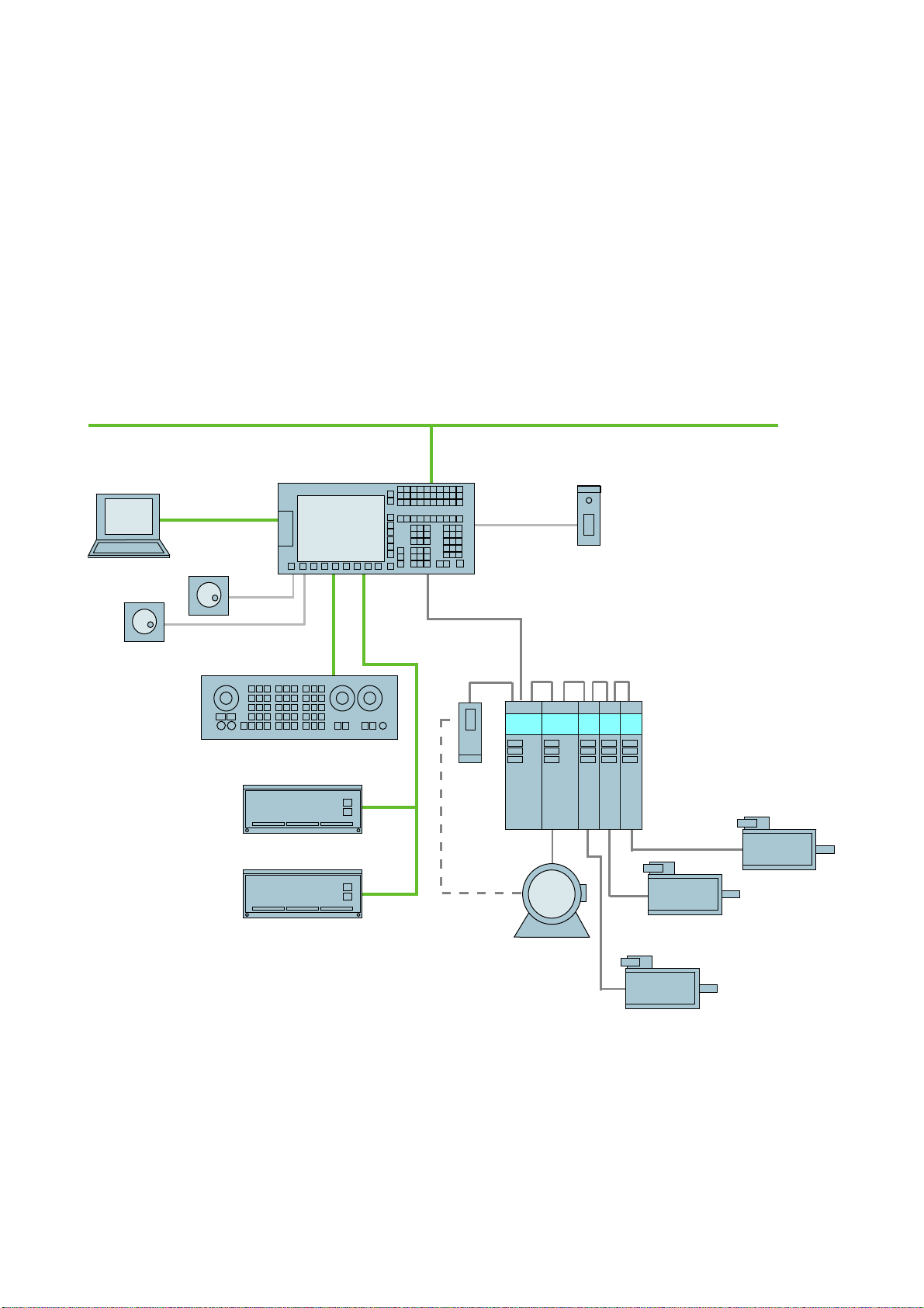
1.1 1.1 System overview
System design
The following configuration shows a typical example:
&RPSDQ\QHWZRUN,QGXVWULDO(WKHUQHW
6,180(5,.'
3HHUWRSHHU
3*3&
'5,9(&/L4
3/&,2LQWHUIDFHEDVHG
[KDQGZKHHOV
RQ352),1(7
1
6,1$870'
6,1$0,&66
0&331
33'31
33'$31
Figure 1-1 Configuration example
Turning and Milling
Commissioning Manual, 09/2009, 6FC5397-3DP20-0BA0
60&
6/0
600
,QGXFWLRQPRWRU
600
600
600
6\QFKURQRXV
PRWRU
6\QFKURQRXV
PRWRU
6\QFKURQRXV
PRWRU
13
Page 14

Scope of delivery and requirements
1.2 Toolbox CD and other available tools
1.2 1.2 Toolbox CD and other available tools
Toolbox CD
The Toolbox CD for SINUMERIK 828D has the following content:
● PLC Programming Tool for Integrated PLC
● Commissioning software for SINAMICS S120
● PLC Library (example)
PLC Programming Tool for Integrated PLC
The following tool is available for programming the PLC: PLC Programming Tool for
Integrated PLC. For the rest of this manual, this will be referred to using the abbreviation
"Programming Tool".
Commissioning software for SINAMICS S120
Until the SINAMICS S120 commissioning functionality is completely available via the user
interface, drive configuration and optimization is performed using the commissioning
software for SINAMICS S120. The PC is connected using the Ethernet interface on the front
of the SINUMERIK 828D.
Note
Ordering data
You can find the ordering data for the following tools in Catalog NC 61.
RCS Commander
The RCS Commander (Remote Control System) is a tool the commissioner can use to
exchange files between the PC and the control very easily, using drag and drop.
For data transmission, the PC is connected directly to the Ethernet interface on the front of
the control. For a point-to-point connection, time-consuming parameterization of the Ethernet
interface is not necessary. All settings are made automatically by the RCS Commander.
The RCS Commander can also access several NCUs sequentially via a company network.
STARTER drive/commissioning software
Drive commissioning for the SINUMERIK 828D can be performed using the STARTER drive
commissioning software. Simple commissioning procedures which are usually performed by
field service staff (such as activating direct measuring systems) can be executed directly via
the SINUMERIK 828D user interface. Advanced commissioning procedures which are
usually performed when the machine is being manufactured (such as drive optimization) can
be executed offline via the commissioning software used for SINAMICS S120.
Turning and Milling
14 Commissioning Manual, 09/2009, 6FC5397-3DP20-0BA0
Page 15

Scope of delivery and requirements
1.3 This is the general sequence for commissioning
1.3 1.3 This is the general sequence for commissioning
Requirements
The mechanical and electrical installation of the system must be completed.
● Check the system visually for:
– Correct mechanical installation with secure electrical connections
– Connection of the power supply
– Connection of shielding and grounding
● Switching on the control and startup in "Normal startup":
Startup of the control is finished when the main screen is shown on the HMI.
Sequence overview
Commissioning of the SINUMERIK 828D is carried out in the following steps:
1. Install the software from Toolbox CD onto PG/PC
See chapter "Scope of delivery and requirements"
2. Create communication connection with the control
See chapter "Communication with the control"
3. Addressing the I/O
See chapter "Addressing the I/O modules"
4. Set HMI
See chapter "Settings on the HMI"
5. PLC functions
See Function Manual Basic Functions (P4)
6. Commission drive and connect probes
See chapter "Configuring drive"
7. Setting NCK machine data
See chapter "Setting NCK machine data"
8. Configuring cycles
See chapter "Configuring cycles"
9. Define maintenance tasks and maintenance intervals
See chapter "Service Planner"
10. Extend machine with additional devices
See chapter "Easy Extend"
11. Tool management
See chapter "Tool management"
Turning and Milling
Commissioning Manual, 09/2009, 6FC5397-3DP20-0BA0
15
Page 16
Scope of delivery and requirements
1.4 Starting up the control
1.4 1.4 Starting up the control
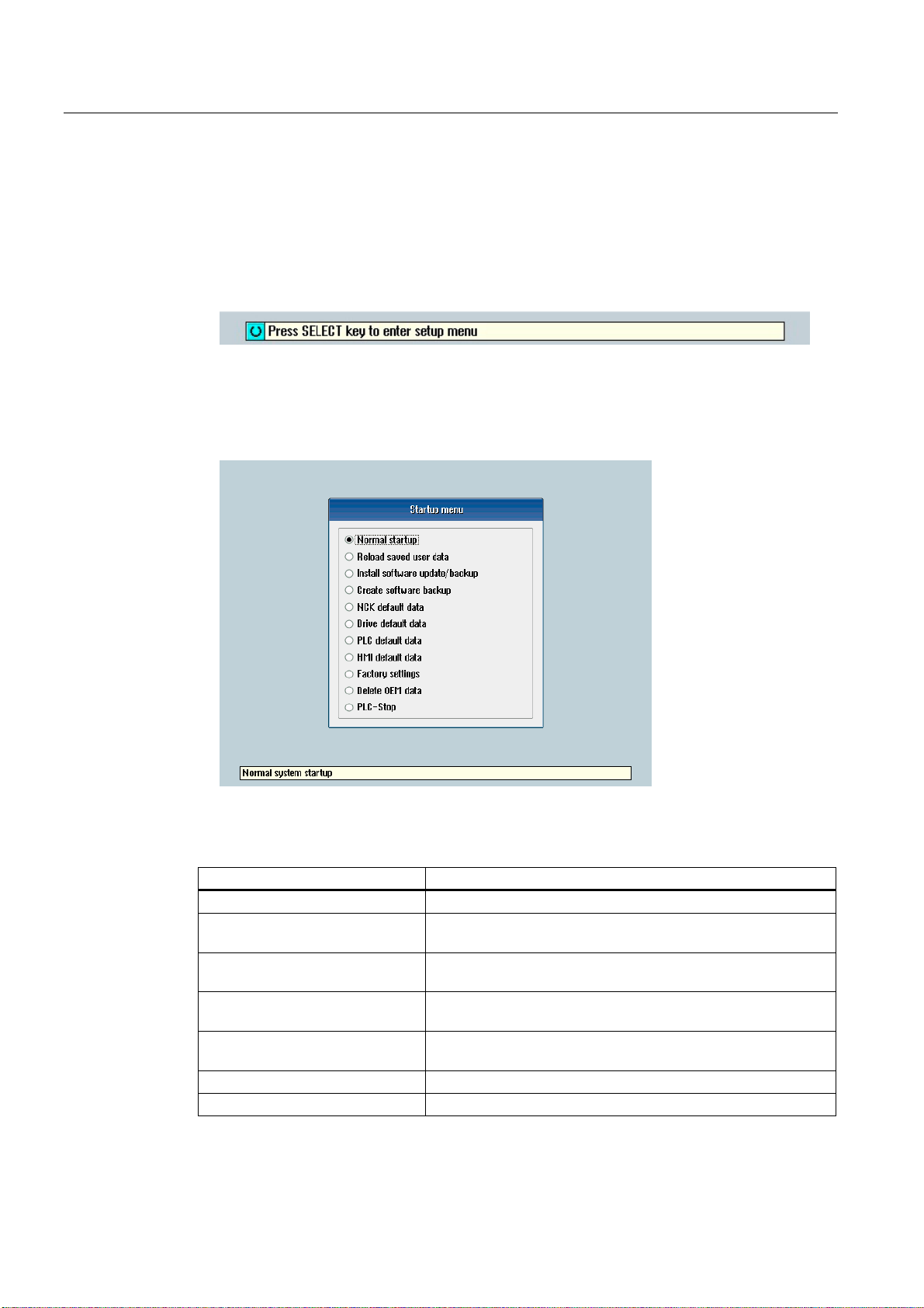
Control startup
Procedure:
1. Switch the control on. The following display then appears during startup:
2. Press the <SELECT> key within three seconds.
3. Then press the following keys in succession:
Menu reset key, HSK2 (horizontal SK2), VSK2 (vertical SK2)
4. The "Setup menu" is displayed, "Normal startup" is the default setting.
Operating modes for startup
Selection Function
Normal startup The system carries out a normal startup.
Reload saved user data The system loads the stored user data ("Save data" softkey)
from the system CompactFlash card.
Install software update/backup An update is installed on the system CompactFlash card from
the user CompactFlash card or USB FlashDrive.
Create software backup A backup of the system CompactFlash card is saved to the user
CompactFlash card or USB FlashDrive.
NCK default data The system loads the Siemens NCK data default settings and
deletes the retentive data on the PLC.
Drive default data The SINAMICS user data is deleted.
PLC default data PLC general reset and load default NOP PLC program.
Turning and Milling
16 Commissioning Manual, 09/2009, 6FC5397-3DP20-0BA0
Page 17

Scope of delivery and requirements
1.4 Starting up the control
Selection Function
HMI default data The HMI user data is deleted.
Factory settings Choice between two cases: No [case 1]/ Yes [case 2]
• Case 1:
The SINAMICS user data is deleted.
Siemens standard NCK data is loaded.
PLC general reset and load default NOP PLC program.
Save HMI user data.
• Case 2:
As case 1 and additionally:
Deletion of the data in the /oem and /addon directories.
Delete OEM data All the data under /oem and /addon is deleted: OEM archives;
OEM alarm texts; Easy Screen application.
PLC stop PLC is stopped.
NOTICE
Replacement of the system CompactFlash card between different PPUs
Because of the system-related dependency between the CompactFlash card and SRAM for
the data storage in the SINUMERIK 828D, the system CompactFlash card should be
considered as a permanently installed EEPROM and should not be replaced!
If this has to be performed for imperative reasons, the replacement of the system
CompactFlash card is detected during startup because of the stored serial number.
The reaction of the control is the loading of saved during startup (backup was performed
previously with "Save data" softkey). If no stored data is found, a startup is performed
automatically with the "NCK default data".
Turning and Milling
Commissioning Manual, 09/2009, 6FC5397-3DP20-0BA0
17
Page 18
Scope of delivery and requirements
1.4 Starting up the control
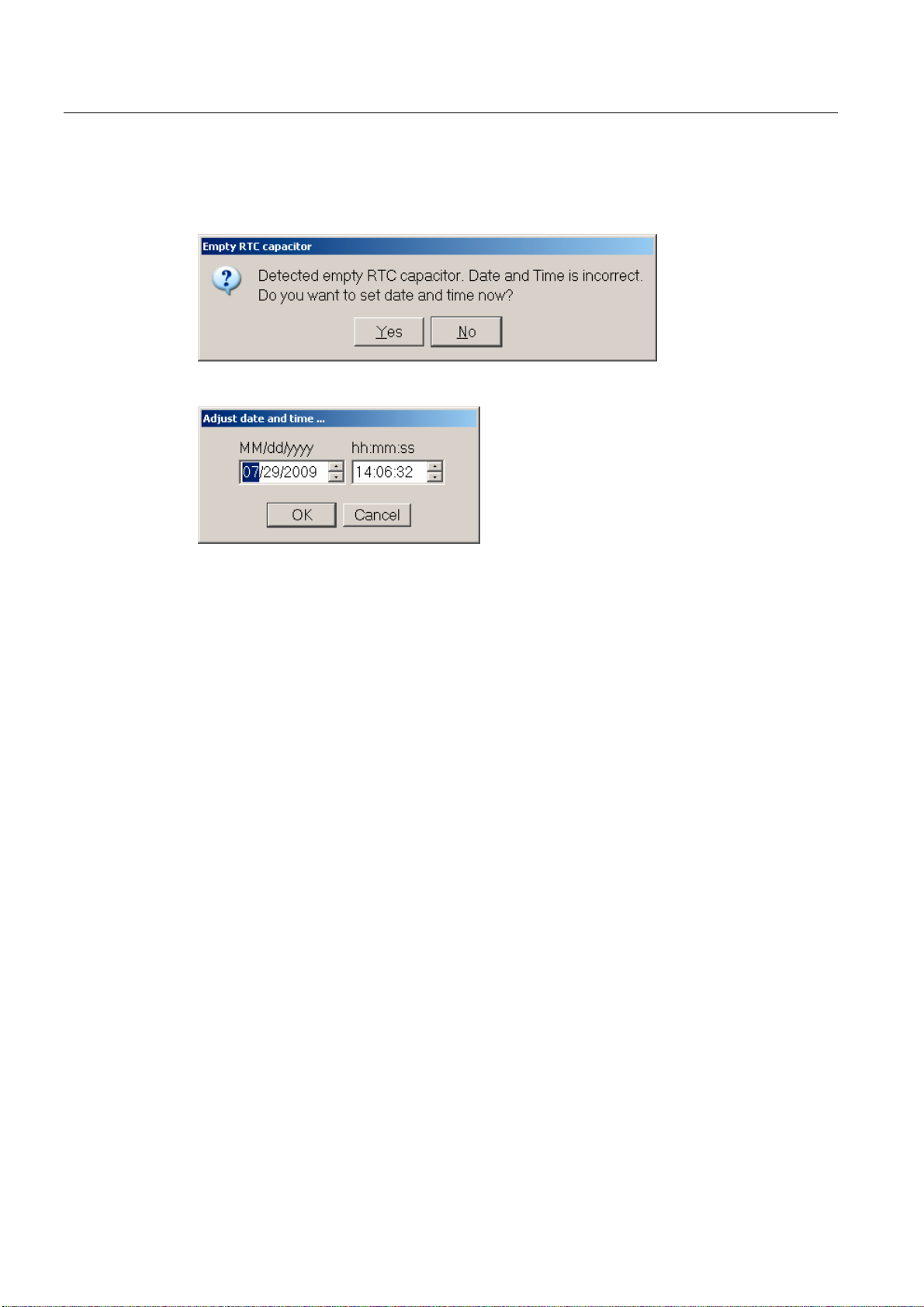
Empty RTC capacitor
If the RTC capacitor is discharged, the following message is issued during startup:
You can then reset the date and time:
The capacitor is then charged again when the control is switched on during startup.
Turning and Milling
18 Commissioning Manual, 09/2009, 6FC5397-3DP20-0BA0
Page 19

Scope of delivery and requirements
1.5 Communication with the control
1.5 1.5 Communication with the control
Creating the connection
An Ethernet cable is needed to connect the control and PG/PC. The following Ethernet
interfaces are available on the control:
● Connection via X127 (behind the flap on the front):
Cable type: Crossed Ethernet cable
At interface X127, the control is preset as a DHCP server, delivering the IP
address192.168.215.1 for a direct connection (peer-to-peer connection).
● Connection via X130 (at the back):
Cable type: Uncrossed Ethernet cable
The interface X130 is the connection to the company network. The IP address that the
PG/PC receives here as a DHCP client is determined by the DHCP server from the
company network or fixed IP address is entered manually.
1.5.1 How to communicate with the control using the Programming Tool
Setting up the communications interface in the Programming Tool
Proceed as follows to set up the network connection in the Programming Tool:
1. Start the Programming Tool.
2. In the navigation bar, click the "Communication" icon or select "View" → "Communication"
from the menu.
3. In the left column, under "Communications parameters" enter 192.168.215.1as the
IP address for X127.
4. Double click on the icon "TCP/IP" at the top right.
Turning and Milling
Commissioning Manual, 09/2009, 6FC5397-3DP20-0BA0
19
Page 20
Scope of delivery and requirements
1.5 Communication with the control
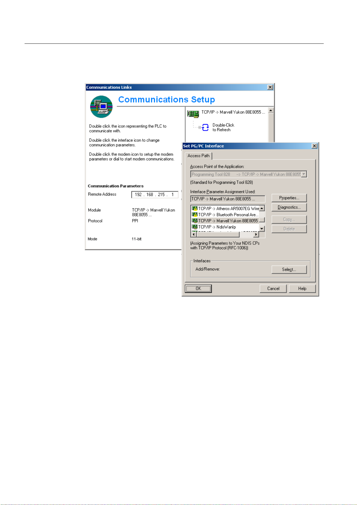
5. In the dialog "PG/PC interface" select the TCP/IP protocol of the PG/PC. Normally this is
the network card of the PC.
Figure 1-2 TCP/IP communications settings
6. Confirm with "OK".
Turning and Milling
20 Commissioning Manual, 09/2009, 6FC5397-3DP20-0BA0
Page 21
Scope of delivery and requirements
1.5 Communication with the control
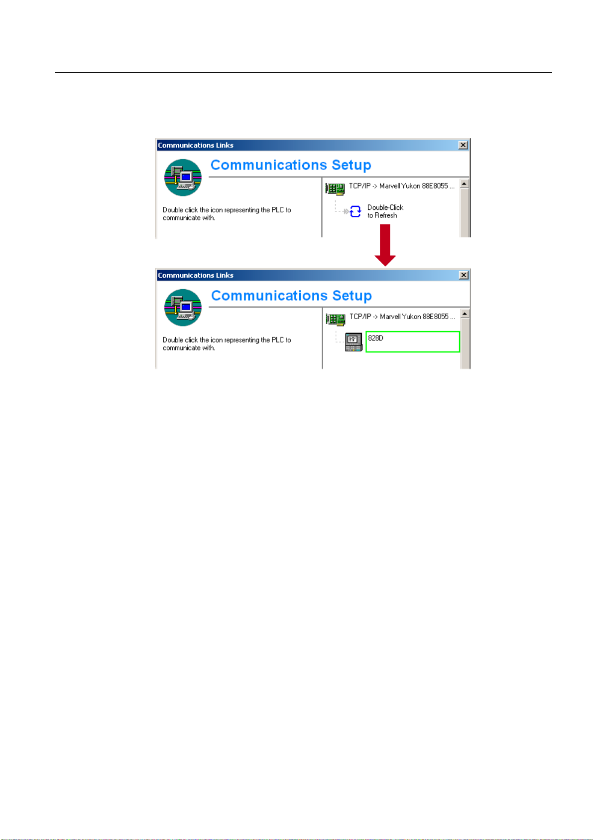
7. Connect by double clicking on the icon "Double click to update". If the connection is made
successfully, the icon will be displayed with a green border:
Figure 1-3 Online connection
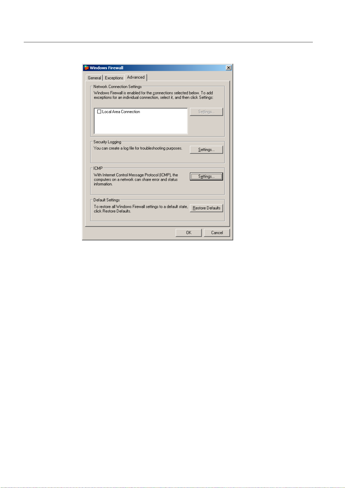
8. If the connection is unsuccessful, the following setting may have to be deactivated:
Select "Control Panel" → "Network Connections"→ "Local Area Connection" "Properties"→
"Advanced"→ "Windows Firewall" → "Settings"→ "Advanced": Deactivate the option "Local
Area Connection".
Turning and Milling
Commissioning Manual, 09/2009, 6FC5397-3DP20-0BA0
21
Page 22
Scope of delivery and requirements
1.5 Communication with the control
Figure 1-4 Deactivate option
Confirm with "OK" and repeat Step 7.
Turning and Milling
22 Commissioning Manual, 09/2009, 6FC5397-3DP20-0BA0
Page 23
Scope of delivery and requirements
1.5 Communication with the control
1.5.2 Example: How to communicate with the control using the NCU Connection Wizard
Requirements
The commissioning software for SINAMICS S120 is installed on the PG/PC. The "NCU
Connection Wizard" is part of this software.
The connection to the control has already been set up via the Programming Tool.
Create connection to control
Procedure for the PG/PC:
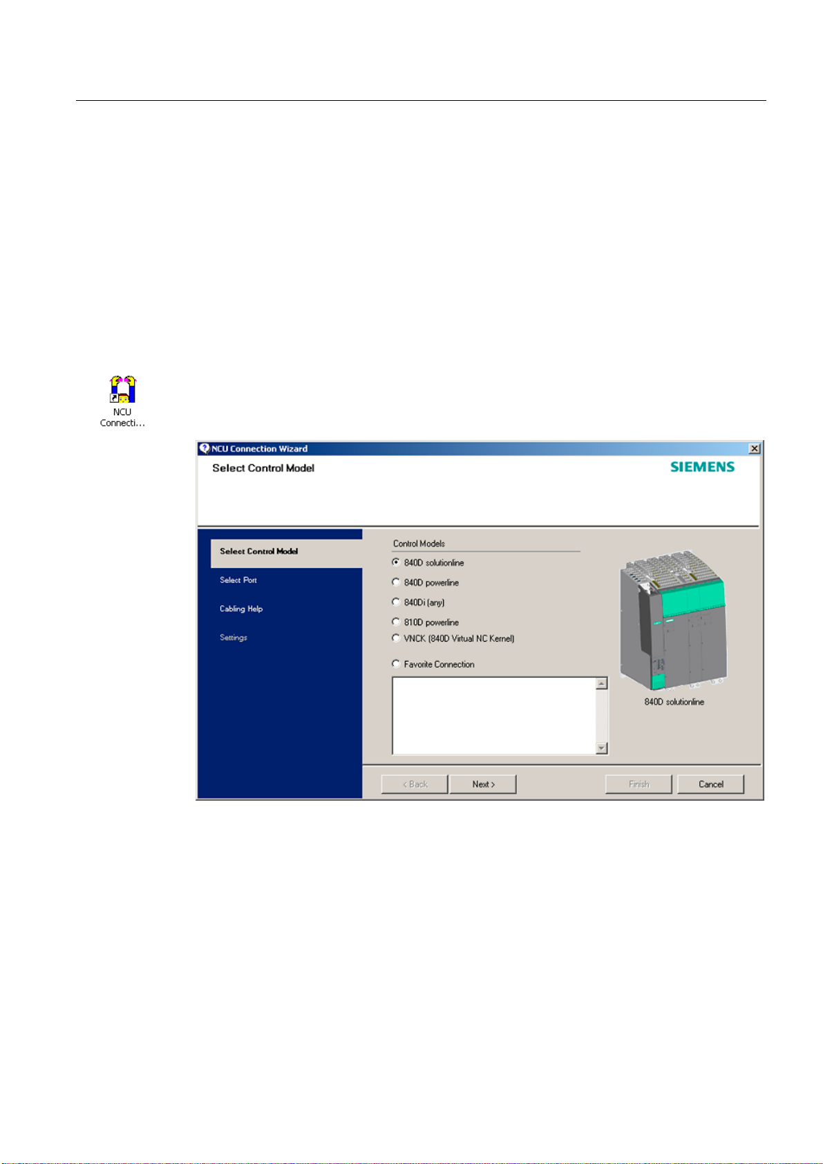
1. Start the "NCU Connection Wizard" via this link or via the Start menu.
2. In the "Select Control Model" dialog, select "840D solution line" for the NCU type
connection to the SINUMERIK 828D.
Figure 1-5 Select the NCU type
Turning and Milling
Commissioning Manual, 09/2009, 6FC5397-3DP20-0BA0
23
Page 24
Scope of delivery and requirements
1.5 Communication with the control
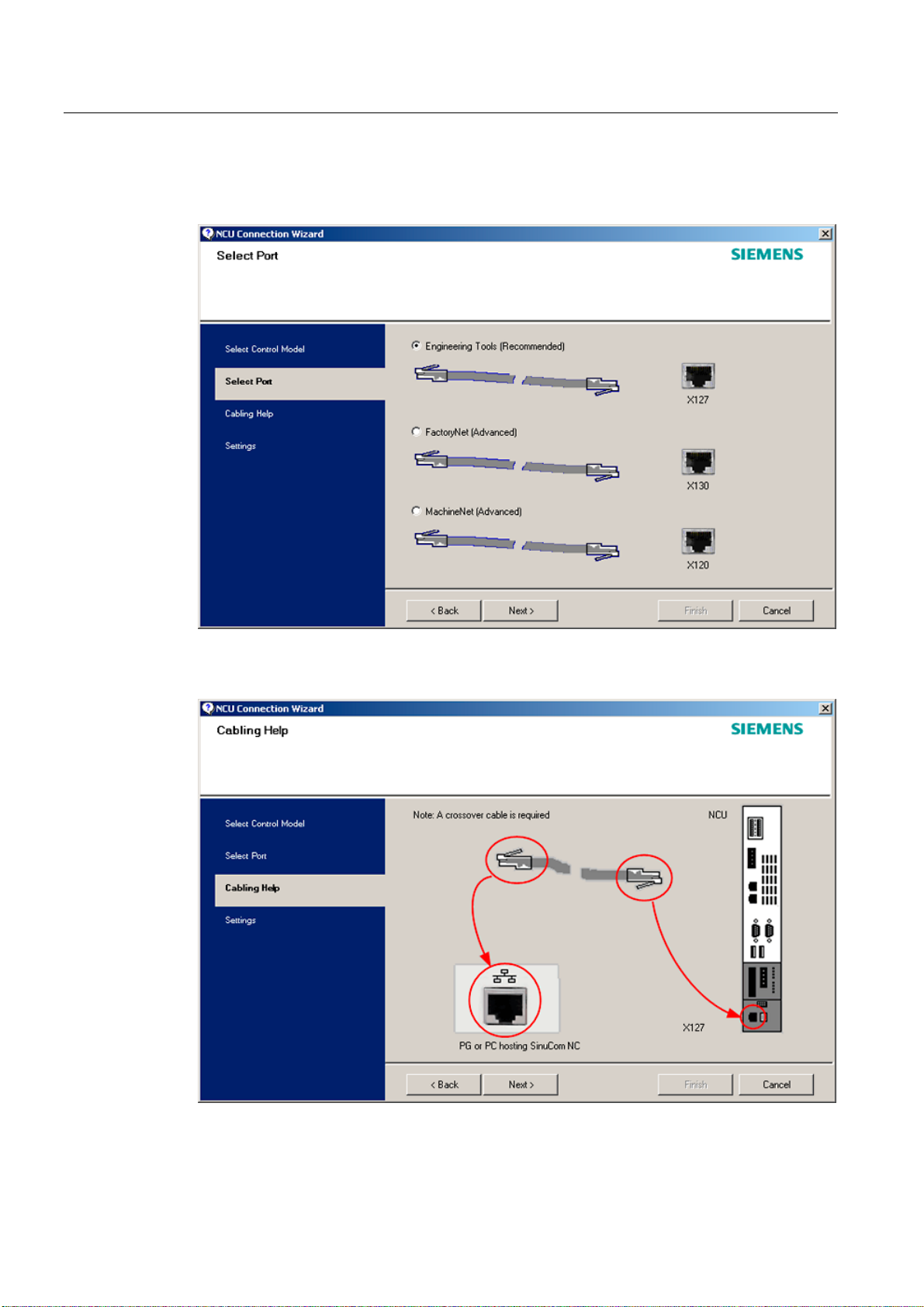
3. In the "Select Port" dialog, select the connection to the control that you have connected
via Ethernet.
Figure 1-6 Select connection
4. Confirm the cable connection for both devices in the"Cabling Help" dialog.
Figure 1-7 Cabling
Turning and Milling
24 Commissioning Manual, 09/2009, 6FC5397-3DP20-0BA0
Page 25

Scope of delivery and requirements
1.5 Communication with the control
5. Check the IP address and enter the name for these settings in the "Settings" dialog.
Figure 1-8 Network settings
1.5.3 How to communicate with the control using the RCS Commander
Connection options
The following options are available for the "RCS Commander" to create a connection with
the control:
● Direct connection (peer-to-peer)
● Network connection
The current status of the connection is shown at the bottom in the RCS Commander status
bar.
Meaning of the buttons:
Connect
Disconnect
Remote control
Turning and Milling
Commissioning Manual, 09/2009, 6FC5397-3DP20-0BA0
25
Page 26
Scope of delivery and requirements
1.5 Communication with the control
Direct connection
NOTICE
Generally only one connection is permitted, i.e. several simultaneous connections to
different controls are not supported: So data exchange between two NCUs using "RCS
Commander" is not possible.
To create a direct connection:
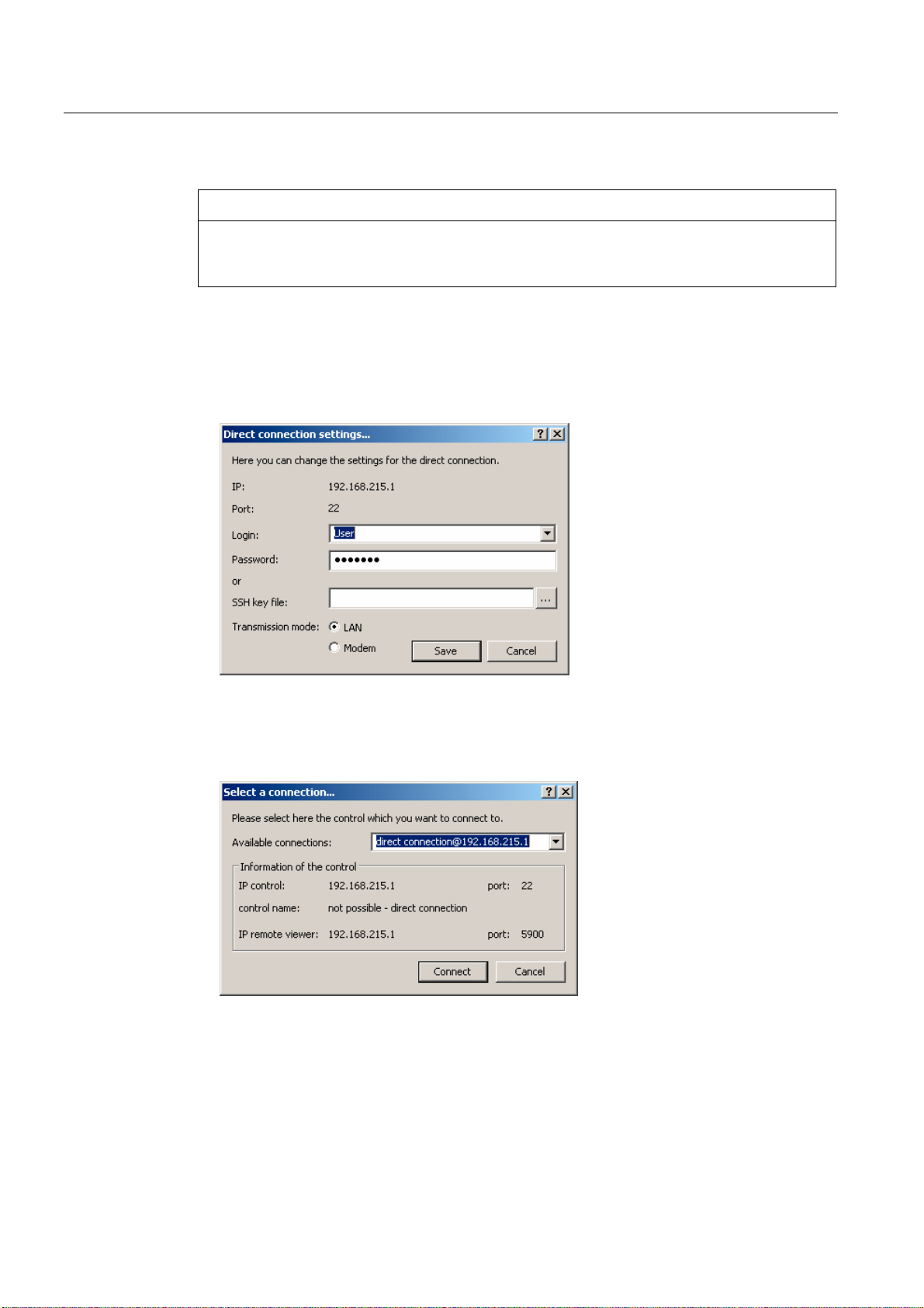
1. The login data is entered in the dialog "Settings" → "Connection" → "Direct connection":
Figure 1-9 Dialog: Login data for direct connection
2. In the menu, select "Connection" → "Connect" → "Direct connection" or click the "Connect"
button.
The following dialog box is displayed:
Figure 1-10 Dialog: Direct connection
3. The last selected direct connection is highlighted. Using the "Connect" button, a
connection to the IP address196.168.215.1 is created.
This dialog does not appear when the direct connection is selected using the menu.
Turning and Milling
26 Commissioning Manual, 09/2009, 6FC5397-3DP20-0BA0
Page 27

Scope of delivery and requirements
1.5 Communication with the control
Network connection
To create a network connection:
1. In the menu, select "Settings" → "Connection" → "Direct connection" or click the "Connect"
button.
Figure 1-11 Dialog: Network connection
2. In the menu, select "Connection" → "Connect" → "Network connection" or select – if
available – one of the previously selected connections.
3. Connection is made to the parameterized control.
Note
SSh key file
As an alternative to entering a password, the user may also use an SSh key for
authentication. Please refer to the Online Help for more information on this topic.
Turning and Milling
Commissioning Manual, 09/2009, 6FC5397-3DP20-0BA0
27
Page 28
Scope of delivery and requirements
1.5 Communication with the control
1.5.4 Communicating with the control via X130
Connection to the company network
The NCU is connected to the company network via the Ethernet interface X130.
The company network is used, for example, to access the network drives.
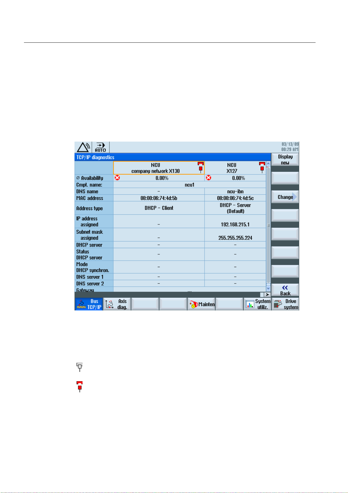
In the "Diagnostics" operating area select the "Bus TCP/IP " → "TCP/IP Diagnostics" →
"Details" softkey with the menu forward key in order to set the parameters for the
communication via X130.
Figure 1-12 Network settings
Connection properties
Company network X130
white Network cable inserted
red Network cable not inserted
Turning and Milling
28 Commissioning Manual, 09/2009, 6FC5397-3DP20-0BA0
Page 29

Scope of delivery and requirements
1.5 Communication with the control
Availability
The availability describes the percentage of faulty data compared to the entire data
volume. Problems in the company network (e.g. logical drives that cannot be reached,
double IP address, etc.) as well as settling time during power up can result in fluctuations in
availability:
green Greater than 95%
yellow 50 - 95 %
red Less than 50%
Note
All information that is not available is marked in the relevant table line with a hyphen "-".
Turning and Milling
Commissioning Manual, 09/2009, 6FC5397-3DP20-0BA0
29
Page 30

Scope of delivery and requirements
1.5 Communication with the control
Turning and Milling
30 Commissioning Manual, 09/2009, 6FC5397-3DP20-0BA0
Page 31

Settings on the HMI
2.1 2.1 Access levels
Access to functions and machine data
The user only has access to information corresponding to a particular access level and the
levels below it. The machine data is assigned different access levels.
The access concept controls access to functions and data areas. Access levels 0 to 7 are
available, where 0 represents the highest level and 7 the lowest level. Access levels 0 to 3
are locked using a password and 4 to 7 using the appropriate key-operated switch settings.
Access level Locked by Area Data class
0 --- System (reserved) System (S)
1 Password: SUNRISE Manufacturer Manufacturer (M)
2 Password: EVENING Servicing Individual (I)
3 Password: CUSTOMER User User (U)
4 Key-operated switch setting 3 Programmer, machine setter User (U)
5 Key-operated switch setting 2 Qualified operator User (U)
6 Key-operated switch setting 1 Trained operator User (U)
7 Key-operated switch setting 0 Semi-skilled operator User (U)
2
The password remains valid until it is reset with the "Delete Password" softkey.
The passwords can be changed after activation.
If, for example, the passwords are no longer known, reinitialization (power up with
"NCK default data") must be carried out. This resets all passwords to the default (see table).
POWER ON does not reset the password.
Note
PI LOGOUT
The password can also be deleted via the PLC.
Turning and Milling
Commissioning Manual, 09/2009, 6FC5397-3DP20-0BA0
31
Page 32

Settings on the HMI
2.1 Access levels
Key-operated switch
Access levels 4 to 7 require a corresponding key-operated switch setting on the machine
control panel. Three keys of different colors are provided for this purpose. Each of these
keys provides access only to certain areas.
Meaning of the key-operated switch settings:
Access level Switch setting Key color
4-7 0 to 3 red
5-7 0 to 2 green
6-7 0 and 1 black
7 0 = Key removal position No key inserted
The key-operated switch setting must always be edited from the PLC user program and
applied to the interface accordingly.
Turning and Milling
32 Commissioning Manual, 09/2009, 6FC5397-3DP20-0BA0
Page 33

Settings on the HMI
2.2 How to set and change the password
2.2 2.2 How to set and change the password
Set password
To change the access level, select the "Start-up" operating area:
1. Press the "Password" softkey.
2. Press the "Set password" softkey to open the following dialog:
Figure 2-1 Set password
Change password
3. Enter a password and confirm this with "OK" or with the <Input> key.
A valid password is acknowledged as set and the currently applicable access level is
displayed. Invalid passwords will be rejected.
4. You must delete the old password before activating a password for a lower access level
than the one activated.
The last valid password is deleted by pressing the "Delete password" softkey. Then the
current key-operated switch setting is valid.
To change the password:
1. Press the "Change password" softkey to open the following dialog:
Figure 2-2 Change password
2. Enter the new password in both fields and then confirm with the "OK" softkey. If both
passwords match, the new password becomes valid and is adopted by the system.
Turning and Milling
Commissioning Manual, 09/2009, 6FC5397-3DP20-0BA0
33
Page 34

Settings on the HMI
2.3 Available system languages
2.3 2.3 Available system languages
System languages
In the basic configuration, the SINUMERIK 828D is delivered with the following system
languages:
● German
● English
● French
● Italian
● Spanish
● Portuguese (Brazil)
● Chinese (simplified)
● Chinese (traditional)
● Korean
All system languages are installed in the SINUMERIK 828D as delivered, so that a change of
language can be carried out directly via the user interface, without having to download
system language data.
Note
Additional languages
No CNC option needs to be ordered for the installation of additional languages not included
in the scope of delivery.
The language files can be ordered on the DVD Additional Languages for SINUMERIK.
Turning and Milling
34 Commissioning Manual, 09/2009, 6FC5397-3DP20-0BA0
Page 35

Settings on the HMI
2.4 How to set the date and time
2.4 2.4 How to set the date and time
Requirement
Changes can only be made with the appropriate access authorization (as of "User" and
higher).
Setting the date and time
Procedure:
1. Select the "Start-up" operating area.
2. Press the "HMI" softkey.
3. Press the "Date/Time" softkey.
The "Date/Time" window opens.
4. Select the required formats for the date and time in the "Format" field.
5. Confirm the entry with the "OK" softkey.
The new date and time details are accepted and output on the first line in the "current"
fields.
Turning and Milling
Commissioning Manual, 09/2009, 6FC5397-3DP20-0BA0
35
Page 36

Settings on the HMI
2.5 Checking and entering licenses
2.5 2.5 Checking and entering licenses
Use
The use of the installed system software and the options activated on a SINUMERIK control
system require that the licenses purchased for this purpose are assigned to the hardware. In
the course of this assignment, a license key is generated from the license numbers of the
system software, the options, as well as the hardware serial number. Here, a license
database administered by Siemens is accessed via the Internet. Finally, the license
information including the license key is transferred to the hardware.
The license database can be accessed using the Web License Manager.
Web License Manager
By using the Web License Manager, you can assign licenses to hardware in a standard Web
browser. To conclude the assignment, the license key must be entered manually on the
control via the user interface.
The Internet address of the Web License Manager is:
See also
http://www.siemens.com/automation/license
Note
SINUMERIK software products
If a license key has not been activated or does not exist for a SINUMERIK software product,
alarm 8080 is output by the control.
Definitions for license management (Page 391)
Turning and Milling
36 Commissioning Manual, 09/2009, 6FC5397-3DP20-0BA0
Page 37

Settings on the HMI
2.5 Checking and entering licenses
2.5.1 How to enter a license key
Requirement
The appropriate licenses are required for the activated options. After licensing the options in
the Web License Manager, you receive a "license key" containing all options requiring a
license and which is only valid for your system CompactFlash card.
To set or reset options, "Manufacturer" access rights are required.
Entering the license key
Procedure:
1. Select the "Start-up" operating area.
2. Press the menu forward key.
3. Press the "Licenses" softkey.
The "Licensing" window opens and gives you the following options:
– Determine the license requirement ("All options" and "Missing licenses" softkeys)
– Softkey: "Exp. license requirement"
– Entry line: "Enter license key"
Figure 2-3 Entering the license key
Turning and Milling
Commissioning Manual, 09/2009, 6FC5397-3DP20-0BA0
37
Page 38

Settings on the HMI
2.5 Checking and entering licenses
2.5.2 How to determine the license requirement
Determining the license requirement
Procedure:
1. Press the "All options" softkey to list all the options that can be selected for this control.
2. Activate or deactivate the required options in the "Set" column:
– Mark the checkbox
– Enter the number of options
Options displayed in red are activated, however are not licensed or insufficiently
licensed.
- OR -
3. Press the "Missing licenses" softkey to display all options that are activated but not
licensed. In the "Set" column, you can deselect the options that you do not require.
Figure 2-4 Licensing (example)
Turning and Milling
38 Commissioning Manual, 09/2009, 6FC5397-3DP20-0BA0
Page 39

Settings on the HMI
2.5 Checking and entering licenses
4. To activate new selected options, press the "Reset (po)" softkey. A safety prompt
appears.
With HMI options, you will need to restart the HMI. Corresponding prompts will appear in
the dialog line.
5. Press the "OK" softkey to trigger a warm restart.
- OR -
6. Press the "Cancel" softkey to cancel the process.
Turning and Milling
Commissioning Manual, 09/2009, 6FC5397-3DP20-0BA0
39
Page 40

Settings on the HMI
$
2.6 Configuring user alarms
2.6 2.6 Configuring user alarms
Creating user PLC alarms
The PLC alarms in the area from 700 000 - 700 247 are configured by the machine
manufacturer. The access level "Manufacturer" is required with the appropriate password.
To enter the user PLC alarms via the user interface, select → "HMI"→ "Alarm texts" in the
"Start-up" operating area.
Then you receive the following selection:
Alarm texts for Name of the xml file
User cycle alarms oem_alarms_cycles
User PLC alarms oem_alarms_plc
User part program message texts oem_partprogram_messages
Loading user PLC alarms
The alarm text files are only loaded during startup.
● "Alarm" attribute: red, is shown in the "alarm list".
● "Message" attribute: black, is shown under "Messages".
Select <MENU SELECT>, then the menu forward key and press the "HMI restart" softkey to
load the alarm texts.
See also
You can find a detailed description of the alarms with system responses and deleting criteria
in: SINUMERIK 828D Diagnostics Manual
2.6.1 Structure of user PLC alarms
Structure of a user PLC alarm
The user PLC alarms have the following structure:
2LOSUHVVXUHWRRORZ
$[LV
DWUHVWSRVLWLRQG
ODUPQXPEHU
Figure 2-5 Alarm structure
Turning and Milling
40 Commissioning Manual, 09/2009, 6FC5397-3DP20-0BA0
9DULDEOH
$ODUPWH[W
Page 41

Settings on the HMI
2.6 Configuring user alarms
The table below shows the mode of operation of the PLC alarms:
1. The alarm is triggered with the appropriate number and output via the PLC signal.
2. If a variable has been configured to this alarm, the value of this variable is in the specified
data word of the PLC variable.
3. The NCK response when the alarm is triggered is defined in the MD14516[x] index (see
table below).
4. The alarm text can be freely selected and may be up to 255 characters long.
Alarm number PLC signal PLC variable Alarm response
(MD)
700 000 DB1600.DBX0.0 DB1600.DBW1000 14516[0] Alarm 1
700 001 DB1600.DBX0.1 DB1600.DBW1004 14516[1] Alarm 2
700 002 DB1600.DBX0.2 DB1600.DBW1008 14516[2] Alarm 3
700 003 DB1600.DBX0.3 DB1600.DBW1012 14516[3] Alarm 4
700 004 DB1600.DBX0.4 DB1600.DBW1016 14516[4] Alarm 5
700 005 DB1600.DBX0.5 DB1600.DBW1020 14516[5] Alarm 6
700 006 DB1600.DBX0.6 DB1600.DBW1024 14516[6] Alarm 7
Continuation:
700 247 DB1600.DBX30.7 DB1600.DBW1988 14516[247] Alarm 248
Alarm text
Defining the NCK response
The following NCK responses are possible:
MD14516[x] Meaning
Bit 0 NC start disabled
Bit 1 Read-in disable
Bit 2 Feed hold for all axes
Bit 3 EMERGENCY STOP
Bit 4 PLC in stop
Bit 5 Reserved
Bit 6 Definition for alarm or message
Bit 7 POWER ON
Bit 6=1: → alarm, Bit 6=0: → message
Turning and Milling
Commissioning Manual, 09/2009, 6FC5397-3DP20-0BA0
41
Page 42

Settings on the HMI
2.6 Configuring user alarms
Configuring alarm texts with variables
The following data types are permitted for variables in the alarm text:
Variable Meaning
%b Binary representation of a 32-bit value
%d Integer decimal number
%f 4 byte floating point number
%i Integer decimal number with sign
%o Integer octal number
%u Unsigned decimal number
%x Integer hexadecimal number
2.6.2 How to create user PLC alarms
Notes for processing
The following points should be observed when processing the files:
● The files should be edited externally on a PG/PC with a text editor (e.g. notepad) or with
● The created alarm text files are copied to the the following directory on the
● To enable the system to recognize the alarm text file, the file name must be written in
● The alarm text file is converted during system startup: A restart of the HMI is necessary to
Procedure
To edit a larger number of alarms, first create 2 or 3 alarms directly on the control. Then the
file oem_alarms_plc_xxx.ts is created and you have a "document template" with the correct
structure, which you can then extend with further alarms. The abbreviation "xxx" stands for
the language in which the file has been created.
1. Select the "Start-up" operating area.
2. Press the "HMI" softkey.
3. Press the "Alarm texts" softkey. The "Select file" window appears.
4. Select "oem_alarms_plc" to create user PLC alarm texts.
an XML editor. The structure must not be altered.
CompactFlash card: oem/sinumerik/hmi/lng
lower case letters.
activate the alarms.
5. Enter the alarm number in the "Number" field and the desired alarm text in the "Text"
field. The alarm numbers and their alarm texts do not have to be consecutive. If an alarm
is triggered without a configured text, only the alarm number is specified.
Turning and Milling
42 Commissioning Manual, 09/2009, 6FC5397-3DP20-0BA0
Page 43

Settings on the HMI
2.6 Configuring user alarms
Searching within the alarm texts
To search for a text or a series of characters:
1. Press the "Find >" softkey. The "Find" window opens; and a new menu is displayed on
the vertical softkey bar.
2. Enter the search term in the "Text" field.
3. Place the cursor in the "Direction" field and choose the search direction (forward,
backward) with the "SELECT" key.
4. Activate the "Case-sensitive" checkbox when a distinction is to be made between upper
and lower case in the entered text.
5. Press the "Find + replace" softkey. The "Find and replace" window appears.
6. Press the "OK" softkey to start the search.
7. Press the "Cancel" softkey to cancel the search.
Other navigation options are:
● Softkey "Go to start":
The cursor jumps to the first entry of the selected alarm text file
● Softkey "Go to end":
The cursor jumps to the last entry of the selected alarm text file.
See also
List of language codes used for file names (Page 383)
Example: How to create an online help for user PLC alarms (Page 60)
2.6.3 Configuring the alarm log
Logging
Configure the alarm log in the "Diagnostics" operating area.
All alarms and messages are logged in chronological order with their raised and cleared time
stamps. The exception are messages of the type "msg" from the NC part program. All alarms
and messages that are no longer active when the log is displayed are also retained
(historical alarm events).
The alarm log is organized as a ring buffer (default setting). The oldest entries are
overwritten with new events in the following cases:
● When the maximum size is exceeded (permissible range: 0 - 32000).
● When the events happened before the last time the system was switched on.
Turning and Milling
Commissioning Manual, 09/2009, 6FC5397-3DP20-0BA0
43
Page 44

Settings on the HMI
2.6 Configuring user alarms
Permanent backup
To save the alarm log permanently, the alarm log is written to the CompactFlash card.
NOTICE
Saving the alarm log
For permanent storage, the alarm log is written to the CompactFlash card which only allows
a limited number of write cycles.
• Therefore, ensure that the backup is only performed when there is a justifiable need!
• Make sure you undo the setting "on every event" if you no longer require storage of the
alarm log.
Default: The alarm log is not backed up.
See also
Filtering events: Set up a filter to limit the number of events in the alarm log. You can find
more details on this in:
● Commissioning Manual Basesoftware and HMI sl, chapter "Configuring alarms".
● List of the alarm number ranges (Page 384)
2.6.4 How to configure the log
Configuring the log
Procedure:
1. Select the "Diagnostics" operating area.
2. Press the "Alarm log" softkey.
3. Press the "Settings" softkey.
4. Enter the desired number in the "Number of entries" field to change the maximum number
5. Select the type of logging under "File write mode":
6. Press the "Save log" softkey to save the alarm log.
The settings become effective only after restarting the HMI.
of raised and cleared events.
Default is 500 events; permissible value range 0 - 32000.
– "Off" if the events are not to be written to a file.
– "On every event" if every event is to be written to a file.
– "Time controlled" if the file is to be overwritten after a particular time interval.
An additional "Time interval" input field appears in which you can specify the time in
seconds.
Turning and Milling
44 Commissioning Manual, 09/2009, 6FC5397-3DP20-0BA0
Page 45

Settings on the HMI
2.6 Configuring user alarms
Editing the configuration file
Procedure:
1. Copy the configuration file "oem_alarmprot_slaesvcconf.xml" from the
/siemens/sinumerik/hmi/template/cfg directory.
2. Insert the file into the directory /oem/sinumerik/hmi/cfg or
/user/sinumerik/hmi/cfg
3. Name the file "slaesvcconf.xml".
4. Open the user-specific file "slaesvcconf.xml" in the editor.
5. Enter the number of events to be output in the <Records type .../> identifier.
The default value is 500. The permissible number is in the range from 0 ... 32000.
OR:
The number of events to be output and the type of logging can also be entered directly via
the user interface:
1. Press the "Alarm log" → "Settings >" softkey in the "Diagnostics" operating area.
As soon as changes are made to the default settings, the "slaesvcconf.xml" file is
automatically created in the /user/sinumerik/hmi/cfg directory.
2. Enter the mode of the permanent storage in the <DiskCare type="int" value="-1"/>
identifier. The following values are possible:
-1: There is no saving of the alarm log (default setting).
0: Each alarm event triggers an immediate saving of the alarm log.
>0: Time for saving the log in seconds:
When there is a change, the log is saved every n > 0 seconds.
3. You adapt the filter for the entry type in the <Filter> identifier.
Here the following applies:
– An alarm event is only entered in the log when it satisfies the filter criteria.
– When several filters are defined, these should be linked using the logical operators
OR or AND.
The settings become effective only after restarting the HMI.
Note
Number of events
Each incoming or outgoing event of an alarm or message requires a separate entry, even
when they belong to the same alarm or message.
Acknowledgement events are also contained in the alarm log. They also require an entry
even when they are not recognizable in the alarm log.
Turning and Milling
Commissioning Manual, 09/2009, 6FC5397-3DP20-0BA0
45
Page 46

Settings on the HMI
2.6 Configuring user alarms
Examples
All alarms that fulfill the following conditions are logged:
● CLEARINFO ≠ 15, therefore without part program messages:
<CONFIGURATION>
<Protocol>
<Filters>
<Siemens_Filter_01 type="QString" value="CLEARINFO NOT 15" />
</Filters>
</Protocol>
</CONFIGURATION>
● "SEVERITY larger than 10" and "smaller than 500" :
<CONFIGURATION>
<Protocol>
<Filters>
<Filter_01 type="QString" value= "SEVERITY HIGHER 10
AND SEVERTY LOWER 500" />
</Filters>
</Protocol>
</CONFIGURATION>
2.6.5 Configuring user alarms with colors
Introduction
For the display of alarms and messages, user specific colors are configured in the alarm
Turning and Milling
46 Commissioning Manual, 09/2009, 6FC5397-3DP20-0BA0
attribute file, which are shown in the alarm or message line.
Note
The colors of the tabular overviews of alarms and messages in the "Diagnostics" operating
area are permanently set and cannot be changed.
Page 47

Settings on the HMI
2.6 Configuring user alarms
Copy the following files into the oem, user or addon branch:
● Alarm attribute file: /siemens/sinumerik/hmi/cfg/oem_slaedatabase.xml
To be able to add further colors for alarms and messages at a later point, use the alarm
attribute file already available or extend other alarm attribute files.
● Configuration file: /siemens/sinumerik/hmi/cfg/oem_slaesvcconf.xml
In the configuration file, notify the "Alarm&Event Service" of the new alarm attribute file.
Alarm colors
The following attributes for colors can be configured for each alarm number:
Identifier <Attribut AttrName= > Meaning
TEXTCOLOR Font color of the alarm/message text
TEXTBACKGROUNDCOLOR Background color of the alarm/message text
NUMBERCOLOR Font color of the alarm number
NUMBERBACKGROUNDCOLOR Background color of the alarm number
2.6.6 How to configure colors for user alarms
General procedure
The sequence includes the following steps:
● Create alarm attribute file
● Define alarm colors
● Create configuration file
● Trigger restart of the HMI
Create alarm attribute file
Procedure:
1. Copy the alarm attribute file "oem_slaedatabase.xml" as a template from the directory
siemens/sinumerik/hmi/template/cfg/
2. Paste the file into one of the following directories:
oem/sinumerik/hmi/cfg/oruser/sinumerik/hmi/cfg/
Turning and Milling
Commissioning Manual, 09/2009, 6FC5397-3DP20-0BA0
47
Page 48

Settings on the HMI
2.6 Configuring user alarms
3. Give the file a new name e.g. "alarm_slaedatabase.xml".
When assigning a name please note:
– Any name can be chosen but it must be written in lower case letters.
– The name must contain a period and file extension.
Example of the copied file: "alarm_slaedatabase.xml"
<?xml version="1.0" encoding="ISO-8859-1"?
<!DOCTYPE SlAeAlarmAttributs>
<SlAeAlarmAttributs Version="01.00.00.00">
<Types>
<Type>
<Category>
<CatDesc>Alarms of the Sinumerk 828 </CatDesc>
<Attributes>
<Attribute AttrName="TEXTCOLOR"
AttrDefault="5003" AttrDataType="10" >
<AttrDesc> Text color of the alarm used
when displayed at the header panel </AttrDesc>
</Attribute>
<Attribute AttrName="TEXTBACKGROUNDCOLOR"
AttrDefault="5004" AttrDataType="10"
<AttrDesc>Background color of the alarm used
when displayed at the header panel </AttrDesc>
</Attribute>
<Attribute AttrName="NUMBERCOLOR"
AttrDefault="5005" AttrDataType="10"
<AttrDesc>Text color of the alarm number used
when displayed at the header panel </AttrDesc>
</Attribute>
<Attribute AttrName="NUMBERBACKGROUNDCOLOR"
AttrDefault="5006" AttrDataType="10"
<AttrDesc>Background color of the alarm number used
when displayed at the header panel </AttrDesc>
</Attribute>
</Attributes>
</Category>
</Type>
</Types>
Turning and Milling
48 Commissioning Manual, 09/2009, 6FC5397-3DP20-0BA0
Page 49

Settings on the HMI
2.6 Configuring user alarms
Define alarm colors
Procedure:
1. Open the created alarm attribute file "alarm_slaedatabase.xml" in the editor.
2. Enter the attribute name of the alarm color type to be changed in the <Attribute
AttrName> identifier.
3. Define the alarm source in the identifier <Sources>:
SourceID="51" SourceURL="/PLC/PMC"
4. Delete the areas that are not being changed.
5. In the <Alarms> identifier, create a separate area for each individual alarm or for an alarm
number range.
6. Enter the alarm number in the <Alarm AlarmID= "..." > identifier, or enter the alarm
number range in the <Range FromAlarmID="..." ToAlarmID= "..."> identifier.
7. Enter the desired color values in the identifiers:
<TEXTCOLOR>
<TEXTBACKGROUNDCOLOR>
<NUMBERCOCLOR>
Note
To insert further alarm sources <Sources>, make sure that the alarm number is always
assigned to the correct alarm source.
You can find the SourceID and the SourceURL in the following table: List of the alarm
number ranges (Page 384)
<NUMBERBACKCOLOR>
Create configuration file
Procedure:
1. Copy the configuration file "oem_slaesvcconf.xml" from the
siemens/sinumerik/hmi/template/cfg directory.
2. Insert the file into directory oem/sinumerik/hmi/cfg or
user/sinumerik/hmi/cfg.
OR:
3. Press the "HMI" → "Alarm texts >" softkey in the "Start-up" operating area.
As soon as an entry is made, the "alarmtexteditor_db_oem_< … >.xml" file is
automatically created in the /oem/sinumerik/hmi/cfg directory.
OR:
4. Edit the "alarmtexteditor_db_oem_< … >.xml"file with an external editor.
5. Transfer the file to the /oem/sinumerik/hmi/cfg directory.
The settings become effective only after restarting the HMI.
Turning and Milling
Commissioning Manual, 09/2009, 6FC5397-3DP20-0BA0
49
Page 50

Settings on the HMI
2.7 Creating OEM-specific online help
2.7 2.7 Creating OEM-specific online help
Overview
In addition to the existing system online help, you also have the option of creating a
manufacturer-specific online help and adding this to the operator software.
This online help is generated in the HTML format, i.e. it comprises HTML documents that are
linked with one another. The subject being searched for is called in a separate window from
a contents or index directory. Similar to a document browser (e.g. Windows Explorer), a list
of possible selections is displayed in the left-hand half of the window and when you click the
required subject, the explanation is displayed in the right-hand half of the window.
Context-sensitive selection of online help pages is not possible.
General sequence:
1. Generating HTML files
2. Generating a help book
3. Integrating the online help in the operator software
4. Saving help files in the target system
2.7.1 Structure and syntax of the configuration file
Syntax description of the "slhlp.xml"
You require the configuration file "slhlp.xml" to integrate the help book in the existing online
help system of the user interface:
Tag Number Meaning
CONFIGURATION 1 Root element of the XML document: Indicates that this
involves a configuration file.
OnlineHelpFiles 1 Introduces the section of the help books.
<help_book> * Introduces the section of a help book.
EntriesFile
III-Technology
1
0,1
File name of the help book with the list of contents and subject
(keyword) entries.
Attributes:
value Name of the XML file
type Data type of the value (QString)
Specifies the technology for which the help book applies.
"All" applies for all technologies.
If the help book applies to several technologies, then the
technologies are listed separated by comma.
Possible values:
All, Universal, Milling, Turning, Grinding, Stroking, Punching
Attributes:
Turning and Milling
50 Commissioning Manual, 09/2009, 6FC5397-3DP20-0BA0
Page 51

Settings on the HMI
2.7 Creating OEM-specific online help
Tag Number Meaning
value Technology data
type Data type of the value (QString)
DisableSearch
0,1
DisableFullTextSearch
0,1
DisableIndex
0,1
DisableContent
DefaultLanguage
0,1
0,1
The following applies to the "Number" column: * means 0 or several
Disable the subject (keyword) search for the help book.
Attributes:
value true, false
type type, data type of the value (bool)
Disable the full text search for the help book.
Attributes:
value true, false
type type, data type of the value (bool)
Disable the subject index for the help book.
Attributes:
value true, false
type type, data type of the value (bool)
Disable the table of contents for the help book.
Attributes:
value true, false
type type, data type of the value (bool)
Abbreviation for the language that should be displayed if the
actual country language is available for the help book.
Attributes:
value chs, cht, deu, eng, esp, fra, ita, kor, ptb ...
type Data type of the value (QString)
Example of a "slhlp.xml" file
The help book "hmi_myhelp.xml" is configured in the following example; the subject index is
not activated:
<?xml version="1.0" encoding="UTF-8" standalone="yes"?>
<!DOCTYPE CONFIGURATION>
<CONFIGURATION>
<OnlineHelpFiles>
<hmi_myhelp>
<EntriesFile value="hmi_myhelp.xml" type="QString"/>
<DisableIndex value="true" type="bool"/>
</hmi_myhelp>
</OnlineHelpFiles>
</CONFIGURATION>
Turning and Milling
Commissioning Manual, 09/2009, 6FC5397-3DP20-0BA0
51
Page 52

Settings on the HMI
2.7 Creating OEM-specific online help
2.7.2 Structure and syntax of the help book
Syntax for the help book
The help book is an XML file in which the structure of the online help is defined. The name of
the file can be freely selected, e.g. "hmi_myhelp". In this file, you define:
● HTML documents
● Contents and subject index
Tag Number Meaning
HMI_SL_HELP 1 Root element of the XML document
BOOK
ENTRY
INDEX_ENTRY
The following applies to the "Number" column:
* means 0 or several
+ means 1 or several
+
*
*
Identifies a help book. The name can be freely selected.
Attributes:
ref Identifies the HTML document that is displayed as the
entry page for the help book.
titel Title of the help book that is displayed in the table of
contents.
helpdir Directory that contains the online help of the help book.
Chapter of the online help
Attributes:
ref Identifies the HTML document that is displayed as entry
page for the chapter.
titel Title of the chapter that is displayed in the table of
contents.
Subject (keyword) to be displayed
Attributes:
ref Identifies the HTML document that is jumped to for this
subject index entry.
titel Title of the subject that is displayed in the subject index.
Turning and Milling
52 Commissioning Manual, 09/2009, 6FC5397-3DP20-0BA0
Page 53

Settings on the HMI
2.7 Creating OEM-specific online help
Formatting the index
You have the following options to format the subject index:
● Single entry: <INDEX_ENTRY ...title="index"/>
● Two two-stage entry, whereby each title has a main and a subentry.
Separate the entries with a comma.
<INDEX_ENTRY ...title="mainIndex_1,subIndex_1 with mainIndex_1"/>
● Two-stage entry, whereby the first title is the main entry and the second title is the
subentry.
Separate the entries with a semicolon.
<INDEX_ENTRY ...title="mainIndex_2;subIndex_2
without mainIndex_1"/>
Figure 2-6 Example: Two-stage index
2.7.3 Description of the syntax for the online help
Rules for creating the HTML files
Generating help files in the HTML format. It is possible to save all information in a single
HTML file or to distribute the information over several HTML files.
The file names are assigned taking into account the following rules:
● References within HTML files should always be specified with relative paths. Only then
can it be ensured that the references function in precisely the same way on both the
development computer as well as on the target system.
● If jumps are to be made to certain points within an HTML file per link, then so-called
anchors must be defined for this purpose.
Example of an HTML anchor:
<a name="myAnchor">This is an anchor</a>
See also: Example: How to create an online help for user PLC alarms (Page 60)
● The contents of HTML documents must be saved with the UTF-8 coding. This guarantees
that the HTML documents are correctly displayed in all of the supported country
languages.
Turning and Milling
Commissioning Manual, 09/2009, 6FC5397-3DP20-0BA0
53
Page 54

Settings on the HMI
2.7 Creating OEM-specific online help
HTML tags
The following sub-set of the HTML functional scope is supported:
Tag Description Comment
a Anchor or link Supported attributes: href and name
address Address
b Bold
big Larger font
blockquote Indented paragraph
body Document body Supported attributes: bgcolor (#RRGGBB)
br Line break
center Centered paragraph
cite Inline citation Same effect as tag i
code Code Same effect as tag tt
dd Definition data
dfn Definition Same effect as tag i
div Document division The standard block attributes are supported
dl Definition list The standard block attributes are supported
dt Definition term The standard block attributes are supported
em Emphasized Same effect as tag i
font Font size, family, color Supported attributes: size, face, and color (#RRGGBB)
h1 Level 1 heading The standard block attributes are supported
h2 Level 2 heading The standard block attributes are supported
h3 Level 3 heading The standard block attributes are supported
h4 Level 4 heading The standard block attributes are supported
h5 Level 5 heading The standard block attributes are supported
h6 Level 6 heading The standard block attributes are supported
head Document header
hr Horizontal line Supported attributes: width (can be specified as absolute or
relative value)
html HTML document
i Italic
img Image Supported attributes: src, width, height
kbd User-entered text
meta Meta-information
li List item
nobr Non-breakable text
ol Ordered list The standard attributes for lists are supported
p Paragraph The standard block attributes are supported (default setting:
left-aligned)
pre Preformated text
s Strikethrough
samp Sample code Same effect as tag tt
Turning and Milling
54 Commissioning Manual, 09/2009, 6FC5397-3DP20-0BA0
Page 55

Settings on the HMI
2.7 Creating OEM-specific online help
Tag Description Comment
small Small font
span Grouped elements
strong Strong Same effect as tag b
sub Subscript
sup Superscript
table Table Supported attributes: border, bgcolor (#RRGGBB),
cellspacing, cellpadding, width (absolute or relative), height
tbody Table body No effect
td Table data cell The standard attributes for table cells are supported
tfoot Table footer No effect
th Table header cell The standard attributes for table cells are supported
thead Table header This is used to print tables that extend over several pages
title Document title
tr Table row Supported attributes: bgcolor (#RRGGBB)
tt Typewrite font
u Underlined
ul Unordered list The standard attributes for lists are supported
var Variable Same effect as tag tt
Block attributes
The following attributes are supported by the tags div, dl, dt, h1, h2, h3, h4, h5, h6, p:
● align (left, right, center, justify)
● dir (ltr, rtl)
Standard attributes for lists
The following attributes are supported by tags ol and ul:
● type (1, a, A, square, disc, circle)
Standard attributes for tables
The following attributes are supported by tags td and th:
● width (absolute, relative, no-value)
● bgcolor (#RRGGBB)
● colspan
● rowspan
● align (left, right, center, justify)
● valign (top, middle, bottom)
Turning and Milling
Commissioning Manual, 09/2009, 6FC5397-3DP20-0BA0
55
Page 56

Settings on the HMI
2.7 Creating OEM-specific online help
CSS properties
The following table includes the supported CSS functional scope:
Property Values Description
background-color <color> Background color for elements
background-image <uri> Background image for elements
color <color> Foreground color for text
text-indent <length>px Indent the first line of a paragraph in pixels
white-space normal | pre | nowrap | pre-
wrap
margin-top <length>px Width of the upper edge of the paragraph in
margin-bottom <length>px Width of the lower edge of the paragraph in
margin-left <length>px Length of the left hand edge of the paragraph in
margin-right <length>px Width of the righthand edge of the paragraph in
vertical-align baseline | sub | super |
middle | top | bottom
border-color <color> Border color for text tables
border-style none | dotted | dashed | dot-
dash | dot-dot-dash | solid |
double | groove | ridge |
inset | outset
background [ <'background-color'> ||
<'background-image'> ]
page-break-before [ auto | always ] Page break before a paragraph/table
page-break-after [ auto | always ] Page break after a paragraph/table
background-image <uri> Background image for elements
Defines how whitespace characters are handled
in HTML documents
pixels
pixels
pixels
pixels
Vertical alignment for text (in tables, only the
values middle, top and bottom are supported)
Border style for text tables
Short notation for background property
Supported CSS selectors
All CSS 2.1 selector classes are supported with the exception of so-called pseudo selector
classes such as :first-child, :visited and :hover.
Turning and Milling
56 Commissioning Manual, 09/2009, 6FC5397-3DP20-0BA0
Page 57

Settings on the HMI
2.7 Creating OEM-specific online help
2.7.4 Example: How to create an OEM-specific help
Requirements
Create the following files:
● Configuration file: "slhlp.xml"
<?xml version="1.0" encoding="UTF-8" standalone="yes"?>
<!DOCTYPE CONFIGURATION>
<CONFIGURATION>
<OnlineHelpFiles>
<hmi_myhelp>
<EntriesFile value="hmi_myhelp.xml" type="QString"/>
<DisableIndex value="false" type="bool"/>
</hmi_myhelp>
</OnlineHelpFiles>
</CONFIGURATION>
● Definition of the help book. "hmi_myhelp.xml"
<?xml version="1.0" encoding="UTF-8"?>
<HMI_SL_HELP language="en-US">
<BOOK ref="index.html" title="Easy Help" helpdir="hmi_myhelp">
<ENTRY ref="chapter_1.html" title="Chapter 1">
<INDEX_ENTRY ref="chapter_1.html" title="Keyword 1"/>
<INDEX_ENTRY ref="chapter_1.html" title="Keyword 2"/>
</ENTRY>
<ENTRY ref="chapter_2.html" title="Chapter 2">
<INDEX_ENTRY ref="chapter_2.html" title="Keyword 2"/>
</ENTRY>
<ENTRY ref="chapter_3.html" title="Chapter 3">
<INDEX_ENTRY ref="chapter_3.html" title="Keyword 3"/>
<ENTRY ref="chapter_31.html" title="Chapter 3.1">
<INDEX_ENTRY ref="chapter_31.html" title="test;Chapter 3.1"/>
</ENTRY
<ENTRY ref="chapter_32.html" title="Chapter 3.2">
<INDEX_ENTRY ref="chapter_32.html" title="test;Chapter 3.2"/>
</ENTRY
</ENTRY>
</BOOK>
</HMI_SL_HELP>
Turning and Milling
Commissioning Manual, 09/2009, 6FC5397-3DP20-0BA0
57
Page 58

Settings on the HMI
2.7 Creating OEM-specific online help
Saving help files in the target system
In the following example, the structure of a help book with the name "Easy Help" with table of
contents and subject index is described.
Procedure:
1. Copy the configuration file "slhlp.xml" to the following directory:
/oem/sinumerik/hmi/cfg
2. Create a directory for the desired language of the online help under the following path:
/oem/sinumerik/him/hlp
Use the specified language code from Chapter List of language codes used for file names
(Page 383).
Note
Notation
The directory names must be written in lower case.
For example, if you are integrating a help in English, create an "eng" directory.
3. Place the help book, e.g. "hmi_myhelp.xml" in the "eng" directory.
/oem/sinumerik/him/hlp/eng/hmi_myhelp.xml
4. Copy the help files to the following directory:
/oem/sinumerik/him/hlp/eng/hmi_myhelp/
The settings become effective only after restarting the HMI.
NOTICE
Updates or changes
For the display of the table of contents and index of a help book and for quicker processing
in the /siemens/sinumerik/sys_cache/hmi/hlp directory, the help files are stored in
binary format: slhlp_<Hilfebuch>_*_<lng>.hmi .
In the example: slhlp_hmi_myhelp_*_eng.hmi
These files must first be deleted so that the changes can take effect and be displayed in the
online help.
Turning and Milling
58 Commissioning Manual, 09/2009, 6FC5397-3DP20-0BA0
Page 59

Settings on the HMI
2.7 Creating OEM-specific online help
Result
The book consists of three chapters with sections:
Figure 2-7 Example: OEM online help
Entries in the subject index:
Figure 2-8 Example: Index
Turning and Milling
Commissioning Manual, 09/2009, 6FC5397-3DP20-0BA0
59
Page 60

Settings on the HMI
2.7 Creating OEM-specific online help
2.7.5 Example: How to create an online help for user PLC alarms
Overview
If a user PLC alarm is triggered, a context-sensitive online help can be created for the
respective alarm, e.g. with explanation and remedy. The online help texts for the user PLC
alarms are managed in the following file: "sinumerik_alarm_oem_plc_pmc.html"
Figure 2-9 Example: Online help of user PLC alarms
Structure of the help file
The following entries are permitted in the help file:
Entry Meaning
<a name="AlarmNo">AlarmNo</a> Hyperlink to the alarm number
<b> .....</b> Help text for the corresponding alarm
<td width="85%">......</td> Text that is displayed after the "Explanation" or "Remedy"
field.
Turning and Milling
60 Commissioning Manual, 09/2009, 6FC5397-3DP20-0BA0
Page 61

Settings on the HMI
2.7 Creating OEM-specific online help
Creating a help file
The file name is language-neutral and must be:
sinumerik_alarm_oem_plc_pmc.html
<?xml version="1.0" encoding="UTF-8" standalone="yes"?>
<!DOCTYPE html PUBLIC>
<html>
<head><title></title></head>
<body>
<table>
...
<tr>
<td width="15%">
<b><a name="700004">700004</a></b></td>
<td width="85%"><b>Help for user PLC alarm 700004 </b></td></tr>
<tr><td valign="top" width="15%"><b>Reaction: </b></td>
<td width="85%">Reaction for user PLC alarm 700004 </td></tr>
<tr><td valign="top" width="15%"><b>Remedy:</b></td>
<td width="85%">Restart control. </td>
</tr>
<br>
<tr>
<td width="15%">
<b><a name="700005">700005</a></b></td>
<td width="85%"><b>Help for user PLC alarm 700005 </b></td></tr>
<tr><td valign="top" width="15%"><b>Reaction: </b></td>
<td width="85%">Reaction for user PLC alarm 700005 </td></tr>
<tr><td valign="top" width="15%"><b>Remedy:</b></td>
<td width="85%">Clear alarm with Reset key. </td>
</tr>
<br>
...
</table>
<p></p>
</body>
</html>
Turning and Milling
Commissioning Manual, 09/2009, 6FC5397-3DP20-0BA0
61
Page 62

Settings on the HMI
2.7 Creating OEM-specific online help
Procedure:
1. Copy the file to one of the following directories:
/oem/sinumerik/hmi/hlp/<lng>/sinumerik_alarm_plc_pmc/
/user/sinumerik/hmi/hlp/<lng>/sinumerik_alarm_plc_pmc/
<lng> stands for the language code.
See also
2. Delete all files in the directory:
/siemens/sinumerik/sys_cache/hmi//hlp
The settings become effective only after restarting the HMI.
List of language codes used for file names (Page 383)
Turning and Milling
62 Commissioning Manual, 09/2009, 6FC5397-3DP20-0BA0
Page 63

Commissioning the PLC
Creating a PLC program
The PLC is commissioned with the Programming Tool. This is a Windows program and is
installed on a PC. A typical Windows easy-to-use online help is available.
If the Programming Tool is called without specifying an existing project, a new project is
implicitly created with the name "Project1". This project can be used immediately to create
the PLC user program and then saved under an arbitrary name and loaded to the control.
Existing projects can be opened in the usual Windows manner.
See also
A detailed description on the operation of the Programming Tool, the properties and the
programming of the PLC as well as further useful functions from the PLC can be found in:
Function Manual Basic Functions /PG/, Chapter PLC for SINUMERIK 828D (P4)
3
Turning and Milling
Commissioning Manual, 09/2009, 6FC5397-3DP20-0BA0
63
Page 64

Commissioning the PLC
3.1 Activating I/O modules
3.1 3.1 Activating I/O modules
General machine data
I/O modules, machine control panel and PN bus coupler are assigned fixed addresses for
the input and output image of the PLC: See table below.
The machine data contains two fields to deactivate the update of the input and output image
of the PLC:
Machine data Value range
12986[i] $MN_PLC_DEACT_IMAGE_LADDR_IN 0 ≤ i ≤ 7 Input addresses
12987[i] $MN_PLC_DEACT_IMAGE_LADDR_O
UT
The SINUMERIK 828D works with a fixed maximum configuration of the I/O modules. As
delivered, the data transfer to the input and output image of the PLC is deactivated for all I/O
modules.
Field with logical input addresses:
MD Logical input address Data transfer to the PLC deactivated
12986[0] 0 1st PP module inactive
12986[1] 9 2nd PP module inactive
12986[2] 18 3rd PP module inactive
12986[3] 27 4th PP module inactive
12986[4] 36 5th PP module inactive
12986[5] 96 PN bus coupler inactive
12986[6] 112 Machine control panel inactive
0 ≤ i ≤ 7 Output addresses
The field of output addresses is empty (default setting): MD12987[i] = -1
If an I/O module is to be activated, its address must not be entered in either MD12986[i] or in
MD12987[i]. Instead, the value -1 ("empty") must be entered.
Example
Two PP modules and the machine control panel are activated:
MD Logical input address Data transfer to the PLC deactivated
12986[0] -1 1st PP module active
12986[1] -1 2nd PP module active
12986[2] 18 3rd PP module inactive
12986[3] 27 4th PP module inactive
12986[4] 36 5th PP module inactive
12986[5] 96 PN bus coupler inactive
12986[6] -1 Machine control panel active
Turning and Milling
64 Commissioning Manual, 09/2009, 6FC5397-3DP20-0BA0
Page 65

Commissioning the PLC
3.1 Activating I/O modules
Note
The use of an input/output address of a deactivated module in the PLC user program does
not trigger an alarm. The PLC user program always works with the image memory. Whether
there is a connection to the physical input/outputs is configured via MD12986[i] and
MD12987[i].
Active modules are then monitored cyclically for failure.
SURJUDP
Figure 3-1 I/O switch
Activating fast onboard I/O for PLC
The PLC of the SINUMERIK 828D use four fast inputs and outputs respectively, which are
provided "onboard" via the X142 connector.
,QSXWV
,%
2XWSXWV
4%
31PRGXOH3/&XVHU
0'>L@
RU
0'>L@
Example: X142.1 corresponds to $A_IN[9]
These four inputs and four outputs are assigned to the NC of the SINUMERIK 828D as
standard and can be jointly assigned to the PLC by changing the following machine data:
Machine data I/O of the NC
assigned
10366[0] $MN_HW_ASSIGN_DIG_FASTIN 10101H 10001H
10368[0] $MN_HW_ASSIGN_DIG_FASTOUT 10101H 10001H
I/O of the PLC
assigned
Turning and Milling
Commissioning Manual, 09/2009, 6FC5397-3DP20-0BA0
65
Page 66

Commissioning the PLC
3.1 Activating I/O modules
IP addresses of the I/O modules
You can find the DIP switch setting for the IP address belonging to the appropriate I/O
module in the following table. The maximum configuration with five PN modules for
PPU 28x.1 and four PN modules for PPU 26x.1 including analog modules, bus coupler and
machine control panel with PLC I/O interface based on PROFINET are taken into account.
Example: setting for machine control panel
21
Figure 3-2 DIP switch
I/O module IP address Input addresses Output addresses
192.168.214. (active with MD12986[i] = -1)
1st PP module digital 9 0 … 8 0 … 5
2nd PP module digital 8 9 … 17 6 … 11
3rd PP module digital 7 18 … 26 12 … 17
4th PP module digital 6 27… 35 18 … 23
5th PP module digital 5 36 … 44 24 … 29
Unassigned 45 30 … 55
Reserved -- 46 … 47 -Reserved -- 48 … 49 -Reserved -- 50 … 51 -Reserved -- 52 … 53 -Reserved -- 54 … 55 -Reserved -- 64 … 71 64 … 71
Reserved -- 72 … 79 72 … 79
Reserved -- 80 ... 87 80 ... 87
Reserved 88 … 95 88 … 95
PN bus coupler 20 96 … 111 96 … 111
External machine control panel
Reserved
2))
64 112 … 125
126 ... 131
112 … 121
122 ... 123
Turning and Milling
66 Commissioning Manual, 09/2009, 6FC5397-3DP20-0BA0
Page 67

Commissioning the drive
4.1 4.1 Configuring the drive
4.1.1 Example of a drive configuration
Overview
The SINAMICS S120 commissioning software is available on the Toolbox CD, free of
charge.
Until the SINAMICS S120 commissioning functionality is completely available via the user
interface, drive commissioning is performed using the commissioning software for
SINAMICS S120. The PG/PC is connected via the Ethernet interface on the front of the
SINUMERIK 828D.
Configuring the drive
For the configuration of the drive, the illustration from chapter System overview (Page 13) is
chosen as an example. The DRIVE-CLiQ connections are connected as in the following
diagram:
4
338 6006006/0
;
;
;
'5,9(&/L4FRQQHFWLRQ
Figure 4-1 DRIVE-CLiQ connections
;
;
;
;
;
;
6SLQGOH
(QFRGHU
600 600
0RWRU
(QFRGHU
0RWRU
(QFRGHU
60&
;
0RWRU
(QFRGHU
Turning and Milling
Commissioning Manual, 09/2009, 6FC5397-3DP20-0BA0
67
Page 68

Commissioning the drive
4.1 Configuring the drive
The following applies to the configuration of 4 axes:
The sequence of the DRIVE-CLiQ connections corresponds to the sequence of the
SINAMICS drive object numbers (= default). Adjustments are only necessary if this setting
does not fit with the sequence in the drive system.
Index Axes SINAMICS drive object
Number Name
1 CU_I_3.3:1
2 SLM_3.3:2
4 MSP1 3 SERVO_3.3:3
1 MX1 4 SERVO_3.3:4
2 MY1 5 SERVO_3.3:5
3 MZ1 6 SERVO_3.3:6
See also
Rules for wiring with DRIVE-CLiQ (Page 393)
Sequence
The sequence is divided into the following steps:
● Create connection to control.
● Step 1: Configure the drive.
● Step 2: Configure the infeed.
● Step 3: Assign the encoders.
● Step 4: Assign the axes.
● Finally: Save the data.
These steps are described in more detail in the following sections.
Turning and Milling
68 Commissioning Manual, 09/2009, 6FC5397-3DP20-0BA0
Page 69

Commissioning the drive
4.1 Configuring the drive
4.1.2 Example: How to configure the drive
Initial state
Before you begin:
● Connect PG/PC with the control: See chapter Example: How to communicate with the
control using the NCU Connection Wizard (Page 23)
● Power up of the control is carried out with "Siemens default data".
● Display in "Start-up" operating area on the control:
Figure 4-2 Control after power up
Turning and Milling
Commissioning Manual, 09/2009, 6FC5397-3DP20-0BA0
69
Page 70

Commissioning the drive
4.1 Configuring the drive
Procedure
To configure the drive:
1. Start the commissioning software for SINAMICS S120.
2. Select the "Start-up" operating area.
3. If necessary, change the password to "Manufacturer" access level.
Display the commissioning software on PG/PC:
Figure 4-3 Start commissioning
Note
Updating firmware
When a drive is connected, the update of the firmware is started automatically.
Alternatively:
The firmware update can also be started via the following softkeys:
Turning and Milling
70 Commissioning Manual, 09/2009, 6FC5397-3DP20-0BA0
Page 71

Commissioning the drive
4.1 Configuring the drive
4. Start commissioning with the "Drive system" softkey (horizontal bar); the following dialog
appears:
Figure 4-4 Drive commissioning
5. To ensure the drive's firmware matches the software level on the control, press the "Load
firmware..." softkey (vertical bar): The current firmware on the control's
CompactFlash card is loaded to the drive.
Figure 4-5 Message on time needed
6. Confirm this message with "Yes".
– During loading, you will be informed of progress with a status display.
– While the firmware is loading, the "RDY" LED flashes alternately red - green on the
appropriate module. When the module is finished, this LED will show a steady green
light. The "DC LINK" LED will show a steady orange light.
Turning and Milling
Commissioning Manual, 09/2009, 6FC5397-3DP20-0BA0
71
Page 72

Commissioning the drive
4.1 Configuring the drive
7. When the firmware has finished loading successfully, confirm this message with "OK":
Figure 4-6 Firmware loaded
Note
The following selection depends on the configuration of the target system:
• Without NX expansion module: "Drive unit" softkey
• With NX expansion module: "Drive system" softkey
Turning and Milling
72 Commissioning Manual, 09/2009, 6FC5397-3DP20-0BA0
Page 73

Commissioning the drive
4.1 Configuring the drive
8. This example is a configuration without NX module. In this example, select the "Drive
unit" softkey (vertical bar).
Figure 4-7 Drive unit: Commissioning
9. Then you receive the message that the device configuration process may last several
minutes.
Figure 4-8 Drive unit: Configuration
Turning and Milling
Commissioning Manual, 09/2009, 6FC5397-3DP20-0BA0
73
Page 74

Commissioning the drive
4.1 Configuring the drive
10. Then you receive the following display:
Figure 4-9 NCK Power On Reset
11. Confirm with "Yes". The system carries out a warm restart. This operation can take
several minutes.
After the warm restart you receive the following selection:
Figure 4-10 Continue configuration
12. To continue commissioning, press the "Drive" softkey.
Turning and Milling
74 Commissioning Manual, 09/2009, 6FC5397-3DP20-0BA0
Page 75

Commissioning the drive
4.1 Configuring the drive
13. Carry out a POWER ON for the drive – as requested in the message: Switch off
completely and then on again. The following will be displayed:
Result
Figure 4-11 Drive data overview
14. Option: To identify the individual Motor Modules, select "Identify via LED": The "RDY"
LED flashes alternately red - orange.
Select the next module with the vertical softkeys "Drive +" and "Drive -".
Step 1 for commissioning of the drives is now complete.
Note
Alternative procedure
If, in the "Configuration" dialog (Fig. Continue configuration), you accidentally press "OK",
continue the configuration after POWER ON with the following selection:
• On the horizontal softkey bar select: "Drive system" → "Drive devices" → "Configuration".
Turning and Milling
Commissioning Manual, 09/2009, 6FC5397-3DP20-0BA0
75
Page 76

Commissioning the drive
4.1 Configuring the drive
4.1.3 Example: How to configure the infeed
Configuring the infeed
Note
If there are alarms that require acknowledgment after switching on, these must be
acknowledged first. Then commissioning can be continued.
Procedure:
1. In the "Overview" dialog, select the vertical softkey "Change", then the following query
appears:
Figure 4-12 Query for further action
2. Here, select the vertical softkey "Change" to continue configuration.
Turning and Milling
76 Commissioning Manual, 09/2009, 6FC5397-3DP20-0BA0
Page 77

Commissioning the drive
4.1 Configuring the drive
3. Then press the horizontal softkey "Infeed" for the following display:
Figure 4-13 Commissioning infeed
4. To configure the infeed, select the vertical softkey "Change".
5. In the following dialog "Configuration - Active Line Module" press "Continue >".
6. In the following dialog "Configuration - Further data" press "Continue >".
7. In the following dialog "Configuration - Terminal wiring" press "Continue >".
Turning and Milling
Commissioning Manual, 09/2009, 6FC5397-3DP20-0BA0
77
Page 78

Commissioning the drive
4.1 Configuring the drive
8. In the following dialog "Configuration - Summary" press "Finish".
The infeed has been configured.
9. Confirm the query if you want to save the data with "Yes".
This process may take several minutes.
Figure 4-14 Infeed: Non-volatile saving of the data
Result
Step 2 for commissioning of the drives is now complete.
4.1.4 Example: How to configure the external encoder
Connecting a direct measuring system
In addition, a direct measuring system is connected for the spindle (see chapter Example of
a drive configuration (Page 67)). The following section describes the configuration.
Turning and Milling
78 Commissioning Manual, 09/2009, 6FC5397-3DP20-0BA0
Page 79

Commissioning the drive
4.1 Configuring the drive
Procedure
To change the configuration of the drive:
1. You pressed the vertical softkey "Change".
Figure 4-15 Change drive
2. Confirm the query with the "Change" softkey.
The dialog "Configuration - Motor" is opened and the drive object 3 = Spindle is selected.
Press "Next >".
3. The next dialog tells you which motor is assigned to the drive.
Press "Next >".
Turning and Milling
Commissioning Manual, 09/2009, 6FC5397-3DP20-0BA0
79
Page 80

Commissioning the drive
4.1 Configuring the drive
4. The next dialog tells you about the motor assignment. Press "Next >".
Figure 4-16 Configuring the motor
5. This dialog tells you the exact data of the motor recognized.
Press "Next >".
6. The next dialog tells you about the configuration of the motor brake.
Press "Next >".
Turning and Milling
80 Commissioning Manual, 09/2009, 6FC5397-3DP20-0BA0
Page 81

Commissioning the drive
4.1 Configuring the drive
7. The next dialog tells you which encoder has already been assigned to this drive object
(= spindle):
Figure 4-17 Assigning the encoder
8. Activate the "Encoder 2" option.
9. Select the encoder "SM_19.Encoder_20" from the selection list.
10. Confirm with the <INPUT> key.
11. Press "Next >".
12. Confirm the query with "OK".
This may take several minutes.
13. While the data is being saved, you receive the following status display:
Figure 4-18 Encoder 2: Saving data
14. The next dialog tells you about the configuration of the control mode.
15. Press "Next >".
16. The next dialog tells you about the BICO connection.
Turning and Milling
Commissioning Manual, 09/2009, 6FC5397-3DP20-0BA0
81
Page 82

Commissioning the drive
4.1 Configuring the drive
17. Press "Next >".
18. At the end you receive a summary showing all the data.
19. If you press "Finish >" you receive the following information:
Figure 4-19 Confirm saving
20. Confirm the saving of the configuration data with "Yes".
Saving can take several minutes.
Result
Step 3 for commissioning of the drives is now complete.
Turning and Milling
82 Commissioning Manual, 09/2009, 6FC5397-3DP20-0BA0
Page 83

Commissioning the drive
4.1 Configuring the drive
4.1.5 Example: How to assign the axes
Assigning axes
After the final save of the Encoder 2 configuration data, the following overview is shown:
Figure 4-20 Drive data overview
Turning and Milling
Commissioning Manual, 09/2009, 6FC5397-3DP20-0BA0
83
Page 84

Commissioning the drive
4.1 Configuring the drive
1. To assign every logical drive a real axis, select the horizontal softkey "Assign axis".
The "Axis assignment" dialog is opened:
Figure 4-21 Assigning axis
Note
Both the following actions are each carried out twice so the softkeys "Change" and
"Accept" must be pressed repeatedly.
2. Press the "Change" softkey to assign an axis to DO number 2.
3. From the selection list choose "MSP1" and press the “Accept” softkey.
4. An NCK Power On Reset is needed to make the assignment effective in the system.
Turning and Milling
84 Commissioning Manual, 09/2009, 6FC5397-3DP20-0BA0
Page 85

Commissioning the drive
4.1 Configuring the drive
5. Press the "Cancel" softkey to assign the other axes first.
Figure 4-22 Assigning axis: Spindle
6. Select the next module with the vertical softkeys "Drive +" and "Drive -".
7. Assign all axes one after another:
Axis Drive
MSP1 SERVO_3.3:3
MX1 SERVO_3.3:4
MY1 SERVO_3.3:5
MZ1 SERVO_3.3:6
Turning and Milling
Commissioning Manual, 09/2009, 6FC5397-3DP20-0BA0
85
Page 86

Commissioning the drive
4.1 Configuring the drive
Accept settings
Finally, carry out the NCK Power On Reset and check the following settings:
Figure 4-23 Confirming Power On Reset
Confirm with "OK" and carry out a restart; not only for the drives and but also for the control.
The following assignment is shown on the PG/PC:
Figure 4-24 Assignment of all axes
Turning and Milling
86 Commissioning Manual, 09/2009, 6FC5397-3DP20-0BA0
Page 87

Commissioning the drive
4.1 Configuring the drive
After the restart, the following machine configuration is displayed on the control:
Result
Figure 4-25 Control: Configuration of all axes
Step 4 for commissioning of the drives is now complete.
Turning and Milling
Commissioning Manual, 09/2009, 6FC5397-3DP20-0BA0
87
Page 88

Commissioning the drive
4.1 Configuring the drive
Data backup
The configuration data is backed up after commissioning in the non-volatile memory with the
vertical softkey "Save data":
Figure 4-26 Data backup
4.1.6 Example: Setting machine data for an axis/spindle
Axis machine data
After the commissioning in the previous example, the following values are set for the axis
machine data:
Axis machine data X Y Z SP A
30130 $MA_GEAR_STEP_MAX_VELO 1 1 1 1 1
30230 $MA_ENC_INPUT_NR 1 1 1 2 1
30240 $MA_ENC_TYPE 1 1 1 1 4
31020 $MA_ENC_RESOL 2048 2048 2048 1024 512
34200 $MA_ENC_REFP_MODE 1 1 1 1 0
Turning and Milling
88 Commissioning Manual, 09/2009, 6FC5397-3DP20-0BA0
Page 89

Commissioning the drive
4.1 Configuring the drive
To operate the axes in the previous example in JOG mode after commissioning the drive,
enter the new values for the following machine data:
Spindle machine data Default setting New value
32000 $MA_MAX_AX_VELO 10000 3000
32010 $MA_JOG_VELO_RAPID 10000 100
32020 $MA_JOG_VELO 2000 50
35100 $MA_SPIND_VELO_LIMIT 10000 3000
35110[0] $MA_GEAR_STEP_MAX_VELO[0] 500 3000
35110[1] $MA_GEAR_STEP_MAX_VELO[1] 500 3000
35130[0] $MA_GEAR_STEP_MAX_VELO_LIMIT[0] 500 3150
35130[1] $MA_GEAR_STEP_MAX_VELO_LIMIT[1] 500 3150
36200[0] $MA_AX_VELO_LIMIT[0] 11500 3300
36200[1] $MA_AX_VELO_LIMIT[1] 11500 3300
Further information on the status of axes and spindle is available in the "Diagnostics"
operating area with the menu forward key:
● The "Axis diagnostics" softkey opens the "Service overview".
● The "Service axis" softkey opens the "Service Axis/Spindle" dialog.
4.1.7 Parameters for the axis/spindle test run
Relevant parameters and terminals
Infeed:
Parameter/terminal Meaning
p0840 ON/OFF1
p0844 1st OFF2
p0845 2nd OFF2
p0852 Enable operation
X21.3 (+24 V) and X21.4 (ground) EP terminals enable (pulse enable)
Drive:
Parameter/terminal Meaning
p0840 ON/OFF1
p0844 1st OFF2
p0845 2nd OFF2
p0848 1st OFF3
Turning and Milling
Commissioning Manual, 09/2009, 6FC5397-3DP20-0BA0
89
Page 90

Commissioning the drive
4.1 Configuring the drive
Parameter/terminal Meaning
p0849 2nd OFF3
p0852 Enable operation
X21.3 (+24 V) and X21.4 (ground) EP terminals enable (pulse enable)
p0864 Infeed enable
p1140 Ramp-function generator enable
p1141 Ramp-function generator start
p1142 Setpoint enable
The drive parameters are set at: "Start-up" operating area → "Drive units" softkey →
"Inputs/outputs"
Figure 4-27 Drive parameters
See also
Further references on the drive:
● SINAMICS S120 Commissioning Manual
● Booksize Power Units Manual
Turning and Milling
90 Commissioning Manual, 09/2009, 6FC5397-3DP20-0BA0
Page 91

Commissioning the drive
4.2 Terminal assignments
4.2 4.2 Terminal assignments
4.2.1 Terminal assignment on X122
Terminal assignment X122 of the Control Unit (PPU)
Pin no. Function Assignment BICO source/sink
1 Input1) ON/OFF1 infeed for:
Line Module with DRIVE-CLiQ connection
"Infeed ready signal" for:
Line Module without DRIVE-CLiQ connection
2 Input "OFF3 – quick stop" CU: r0722.1 Each drive
3 Input SH/SBC 1 - Group 1
SINAMICS Safety Integrated
(SH enable = p9601)
4 Input SH/SBC 1 - Group 2
SINAMICS Safety Integrated
(SH enable = p9601)
5 Ground for pins 1...4
6 +24 V
7 Output SH/SBC 1 - Group 1
SINAMICS Safety Integrated
8 Output SH/SBC 1 - Group 2
SINAMICS Safety Integrated
9 Ground for pins 7, 8, 10, 11
10 Input BERO 1 - zero mark substitute CU: r0722.10 Drive p0495 = 2
11 Input Probe 1: Distributed measurement
(MD13210=1)
12 Ground for pins 7, 8, 10, 11
1)
Low-high edge required
CU: r0722.0 Infeed p0840
SLM X21.1 Drive p0864
2nd OFF3, p0849
CU: r0722.2 p9620 (all drives in the
group)
CU: r0722.3 p9620 (all drives in the
group)
CU: p0738 p9774 bit 1
BICO from CU after
the first drive in the
group
CU: p0739 p9774 bit 1
BICO from CU after
the first drive in the
group
CU: p0680[0]=0 Every drive p0488
Index=encoders
1,2,3=3
Turning and Milling
Commissioning Manual, 09/2009, 6FC5397-3DP20-0BA0
91
Page 92

Commissioning the drive
4.2 Terminal assignments
4.2.2 Terminal assignment on X132
Terminal assignment X132 of the Control Unit (PPU)
Pin no. Function Assignment BICO source/sink
1 Input Digital input $A_IN[1] CU: r0722.4 CU: p2082[0]
2 Input Digital input $A_IN[2] CU: r0722.5 CU: p2082[1]
3 Input Digital input $A_IN[3] CU: r0722.6 CU: p2082[2]
Input Digital input $A_IN[4] CU: r0722.7 CU: p2082[3] 4
Input Line contactor feedback signal
(when configured in the HMI)
5 Ground for pins 1...4
6 +24 V
Output Infeed: in operation
(LM with DRIVE-CLiQ connection)
Output Digital output $A_OUT[4] CU: 2091.3
Output Infeed: Ready for switching on
(LM with DRIVE-CLiQ connection)
Output Digital output $A_OUT[3] CU: 2091.2
9 Ground for pins 7, 8, 10, 11
10
12 Ground for pins 7, 8, 10, 11
Output Digital output $A_OUT[2] CU: 2091.1 CU: p0744
Output Line contactor control
(when configured in the HMI)
Input BERO 2 - zero mark substitute CU: r0722.14 Drive p0495 = 5
Input 2nd OFF 2 CU: r0722.14 Drive p0845
Output Digital output $A_OUT[1] CU: 2091.0 CU: p0745 11
Input Probe 2: Distributed measurement
(MD13210=1)
CU: r0722.7 LM: p0860
LM: r0863.0 CU: p0742 7
LM: r0899.0 CU: p0743 8
LM: r0863.1 CU: p0744
CU: p0680[1]=0
CU: p0728 bit 15=0
Every drive p0489
Index=encoders
1,2,3=6
Turning and Milling
92 Commissioning Manual, 09/2009, 6FC5397-3DP20-0BA0
Page 93

Commissioning the drive
4.2 Terminal assignments
4.2.3 Terminal assignment on X122 for a Numeric Control Extension
Terminal assignment X122 on the NX
Pin no. Function Assignment BICO source/sink
1 Input "Infeed ready signal" NX: r0722.0 Drive p0864
2 Input "OFF3 – quick stop"
Function: Braking with a configurable OFF3
ramp (p1135, p1136, p1137); thereafter,
pulse suppression and switching on inhibited.
The drive comes to a controlled stop.
The braking response can be set separately
for each servo (behavior similar to that of
terminal 64).
3 Input SH/SBC 1 - Group 1
SINAMICS Safety Integrated
(SH enable = p9601)
4 Input SH/SBC 1 - Group 2
SINAMICS Safety Integrated
(SH enable = p9601)
5 Ground for pins 1...4
6 Ground for pins 7, 8, 10, 11
7 Output SH/SBC 1 - Group 1
SINAMICS Safety Integrated
8 Output SH/SBC 1 - Group 2
SINAMICS Safety Integrated
9 Ground for pins 7, 8, 10, 11
Input BERO 1 - zero mark substitute NX: r0722.10 Drive p0489 = 2 10
Input Probe 2: Distributed measurement NX: p0680[1]=0
11
12 Ground for pins 7, 8, 10, 11
Input BERO 2 - zero mark substitute NX: r0722.11 Drive p0488 = 3
Input Probe 1: Distributed measurement NX: p0680[0]=0
Input 2nd OFF 2 NX: r0722.11 Drive p0845
NX: r0722.1 Each drive
2nd OFF3, p0849
NX: r0722.2 p9620 (all drives in the
group)
NX: r0722.3 p9620 (all drives in the
group)
NX: p0738 p9774.1
BICO from CU after the 1st
drive in the group
NX: p0739 p9774.1
BICO from CU after the 1st
drive in the group
Every drive on NX: p0489
p0728 bit 10=0
p0728 bit 11=0
Index=encoders 1,2,3=2
Every drive on NX: p0488
Index=encoders 1,2,3=3
Note
The ON/OFF1 and OFF3 enables are only required on terminal X122 of the CU.
Turning and Milling
Commissioning Manual, 09/2009, 6FC5397-3DP20-0BA0
93
Page 94

Commissioning the drive
4.2 Terminal assignments
4.2.4 Example: Circuitry for a CU with line contactor
Example
The circuitry shown refers to the assignment of the terminals in the previous chapters.
3/&&8
6LJQDOVXSSOLHG5HDG\IRU
VZLWFKLQJRQ
U
2))
2))
2XWSXW
;
,QSXW
;
,QSXW
;
:LWKRXW3/&ORJLF
-XPSHU!!
(0(5*(1&<6723
6DIHW\UHOD\
RU
,QSXW
2XWSXW
2XWSXW
,QSXW
2XWSXW
RU
/LQHFRQWDFWRUFRQWURO
U
1RWH
%,&2LQWHUFRQQHFWLRQRI
OLQHFRQWDFWRUFRQWURO
DFFRUGLQJWRWHUPLQDO
GLDJUDPUHTXLUHG
/LQHFRQWDFWRUIHHGEDFNVLJQDO
6LJQDOVXSSOLHG2SHUDWLRQ
U
2XWSXW
;
/LQHFRQWDFWRU
,QSXW
;
2XWSXW
;
Figure 4-28 Circuitry for a Control Unit with line contactor
b9
(QDEOHVYLDWKH3/&XVHUSURJUDP
,QSXW
Turning and Milling
94 Commissioning Manual, 09/2009, 6FC5397-3DP20-0BA0
Page 95

Commissioning the drive
4.2 Terminal assignments
Smart Line Module connection
The connections for the digital in/outputs X122 and X132 are on the rear side of the control.
0DLQVZLWFK
/LQHILOWHU
/LQHUHDFWRU
/
/
/
3(
/
/
/
3(
0
;
'2
&8
'2
&8
/LQH
FRQWDFWRU
9
',
&8
'2
&8
',
',
&8
&8
0
'2
&8
;
;
6PDUW/LQH0RGXOH
'25HDG\
'2:DUQLQJ,W
(39
(30
/('V
9
','LVDEOH
',5HVHW
0
:9;8
5($'<
'&/,1.
H[W
9
0
0
'&3
'&1
① Early opening contact t > 10 ms, 24 VDC and ground must be applied for operation
② DI/DO controlled by the Control Unit
③ No additional load permitted downstream of line contactor
④ The current carrying capacity of the DO must be observed; an output interface must be used if
required.
⑤ DO high, feedback deactivated (a jumper can be inserted between X22 pin 1 and pin 2 for
permanent deactivation).
⑥ X22 pin 4 must be connected to ground (external 24 V).
⑦ Contacting via rear mounting panel or shielding buses in accordance with EMC installation
guideline
⑧ 5 kW and 10 kW line filters via shield connection
⑨ Signal output of the control, to avoid interference of the 24 VDC supply on the EP terminal.
⑩ Connect via BICO to parameter p0864 → X122.1
Figure 4-29 Example: SLM connection
Turning and Milling
Commissioning Manual, 09/2009, 6FC5397-3DP20-0BA0
8 :9
95
Page 96

Commissioning the drive
4.2 Terminal assignments
ON/OFF1 enable: Connection of Smart Line Module pin X21.1 → X122.1 SINUMERIK 828D
Connect further input and output signals to the PLC I/O:
● DI → PLC inputs
● DO → PLC outputs
See also
Additional information can be found in:
● SINUMERIK 828D Manual PPU
● SINAMICS S120 Manual Booksize Power Units
NOTICE
DSC operation
Parameterization of the combination STIFFNESS_CONTROL_ENABLE=1 and
ENC_FEEDBACK_POL= -(encoder inversion) is not permitted.
The encoder inversion must be performed in the drive parameter p0410 bit 1 of the
SINAMICS.
• DSC operation is preset for motor measuring systems.
• DSC operation must be explicitly activated for external measuring systems.
Requirement: Message frame ≥ 116
SINAMICS drive parameters:
p1192[0] encoder selection
p1193[0] encoder adaptation factor
Turning and Milling
96 Commissioning Manual, 09/2009, 6FC5397-3DP20-0BA0
Page 97

Commissioning the drive
4.2 Terminal assignments
4.2.5 Connecting the probes
Connecting the probes
The probes are connected to both the SINUMERIK 828D CU and the NX:
1st probe to terminal X 122 pin 11/X122 pin 11 of the NX
Machine data
2nd probe to terminal X 132 pin 11/X122 pin 10 of the NX
Note
A precondition for measuring with the SINUMERIK 828D is that the distributed (local)
measurement function has been parameterized.
Central measurement is not possible with SINUMERIK 828D.
The following machine data should be checked and adjusted if necessary:
● General machine data:
MD13200[0] $MN_MEAS_PROBE_LOW_ACTIVE = 0 or 1
MD13200[1] $MN_MEAS_PROBE_LOW_ACTIVE = 0 or 1
Value 0 = deflected state 24 V (default)
Value 1 = deflected state 0 V
MD13210 $MN_MEAS_TYPE = 1 distributed measurement
● Axis-specific machine data:
MD30244[0] $MA_ENC_MEAS_TYPE = 1 for all axes
MD30244[1] $MA_ENC_MEAS_TYPE = 1 for all axes
Note
The machine data MD13210 and MD30244 are preset to the value 1 and cannot be
changed! (Data class: SYSTEM)
Turning and Milling
Commissioning Manual, 09/2009, 6FC5397-3DP20-0BA0
97
Page 98

Commissioning the drive
4.2 Terminal assignments
● Control Unit parameters:
P0680[0] Central probe input terminal = 0
P0680[1] Central probe input terminal = 0
p0680[2] Central probe input terminal = 0
The first probe is connected to terminal X122 pin 11, the second probe to terminal X132
pin 11 of the SINUMERIK 828D and, if present, on the NX10 module to terminal X122
pin 10.
A precondition is the switichover of pin X132.11 from output to input.
Set CU input or output = set p0728 bit 15 to 0 (DI/DO X132.11)
● Drive parameters:
p0488[0] Probe 1 input terminal: Encoder 1 = 3 → connector X 122.11
p0488[1] Probe 1 input terminal: Encoder 2 = 3 → connector X 122.11
p0488[2] Probe 1 input terminal: Encoder 3 = 0 → not used
p0489[0] Probe 2 input terminal: Encoder 1 = 6 → connector X 132.11
p0489[1] Probe 2 input terminal: Encoder 2 = 6 → connector X 132.11
p0489[2] Probe 2 input terminal: Encoder 3 = 0 → not used
The second probe at terminal X122.10 must be parameterized for all axes that are
parameterized on the NX module:
p0489[0] Probe 2 input terminal: Encoder 1 = 6 → connector X 122.10
p0489[1] Probe 2 input terminal: Encoder 2 = 6 → connector X 122.10
p0489[2] Probe 2 input terminal: Encoder 3 = 0 → not used
Note
All drives must be parameterized.
Turning and Milling
98 Commissioning Manual, 09/2009, 6FC5397-3DP20-0BA0
Page 99

Commissioning the drive
4.2 Terminal assignments
Terminals
;;;;
6,180(5,.'
6<1&
)$8/7
09
Figure 4-30 Connecting the probes with NX module
;
9
0
0
;
0
0
1XPHULFDOH[WHQVLRQ1;
',
',
',
',
0
0
','2
','2
0
','2
','2
0
'5,9(&/L4VRFNHW
'5,9(&/L4VRFNHW
'5,9(&/L4VRFNHW
'5,9(&/L4VRFNHW
7KHSUREHVPXVWEHFRQQHFWHGWRWKH
FRQWURODQGWRWKH1;PRGXOH
3UREH3UREH
Probe status
DB2700 General signals from NCK [r]
NCK → PLC interface
Byte Bit 7 Bit 6 Bit 5 Bit 4 Bit 3 Bit 2 Bit 1 Bit 0
DBB0 EMER-
dimension
system
See also
Measuring cycles and measurement functions (Page 186)
Turning and Milling
Commissioning Manual, 09/2009, 6FC5397-3DP20-0BA0
GENCY
STOP active
Probe actuated DBB1 Inch
Probe 2 Probe 1
99
Page 100

Commissioning the drive
4.2 Terminal assignments
Turning and Milling
100 Commissioning Manual, 09/2009, 6FC5397-3DP20-0BA0
 Loading...