

Page 1

SINUMERIK
SINUMERIK 840D sl / 828D
Fundamentals
Programming Manual
Preface
Fundamental Geometrical
Principles
Fundamental Principles of
NC Programming
Creating an NC program
Tool change
Tool offsets
Spindle motion
Feed control
Geometry settings
Motion commands
Tool radius compensation
Path action
Coordinate transformations
(frames)
Auxiliary function outputs
Supplementary commands
Other information
Tables
Appendix
1
2
3
4
5
6
7
8
9
10
11
12
13
14
15
16
A
Valid for
Control
SINUMERIK 840D sl / 840DE sl
SINUMERIK 828D
Software Version
CNC software 4.5 SP2
03/2013
6FC5398-1BP40-3BA1
Page 2

Legal information
Warning notice system
This manual contains notices you have to observe in order to ensure your personal safety, as well as to prevent
damage to property. The notices referring to your personal safety are highlighted in the manual by a safety alert
symbol, notices referring only to property damage have no safety alert symbol. These notices shown below are
graded according to the degree of danger.
DANGER
indicates that death or severe personal injury will result if proper precautions are not taken.
WARNING
indicates that death or severe personal injury may result if proper precautions are not taken.
CAUTION
indicates that minor personal injury can result if proper precautions are not taken.
NOTICE
indicates that property damage can result if proper precautions are not taken.
If more than one degree of danger is present, the warning notice representing the highest degree of danger will
be used. A notice warning of injury to persons with a safety alert symbol may also include a warning relating to
property damage.
Qualified Personnel
The product/system described in this documentation may be operated only by personnel qualified for the specific
task in accordance with the relevant documentation, in particular its warning notices and safety instructions.
Qualified personnel are those who, based on their training and experience, are capable of identifying risks and
avoiding potential hazards when working with these products/systems.
Proper use of Siemens products
Note the following:
WARNING
Siemens products may only be used for the applications described in the catalog and in the relevant technical
documentation. If products and components from other manufacturers are used, these must be recommended
or approved by Siemens. Proper transport, storage, installation, assembly, commissioning, operation and
maintenance are required to ensure that the products operate safely and without any problems. The permissible
ambient conditions must be complied with. The information in the relevant documentation must be observed.
Trademarks
All names identified by ® are registered trademarks of Siemens AG. The remaining trademarks in this publication
may be trademarks whose use by third parties for their own purposes could violate the rights of the owner.
Disclaimer of Liability
We have reviewed the contents of this publication to ensure consistency with the hardware and software
described. Since variance cannot be precluded entirely, we cannot guarantee full consistency. However, the
information in this publication is reviewed regularly and any necessary corrections are included in subsequent
editions.
Siemens AG
Industry Sector
Postfach 48 48
90026 NÜRNBERG
GERMANY
Order number: 6FC5398-1BP40-3BA1
Ⓟ 04/2013 Technical data subject to change
Copyright © Siemens AG 1995 - 2013.
All rights reserved
Page 3

Preface
SINUMERIK documentation
The SINUMERIK documentation is organized in the following categories:
● General documentation
● User documentation
● Manufacturer/service documentation
Additional information
You can find information on the following topics at www.siemens.com/motioncontrol/docu:
● Ordering documentation/overview of documentation
● Additional links to download documents
● Using documentation online (find and search in manuals/information)
Please send any questions about the technical documentation (e.g. suggestions for
improvement, corrections) to the following address:
docu.motioncontrol@siemens.com
My Documentation Manager (MDM)
Under the following link you will find information to individually compile OEM-specific
machine documentation based on the Siemens content:
www.siemens.com/mdm
Training
For information about the range of training courses, refer under:
● www.siemens.com/sitrain
SITRAIN - Siemens training for products, systems and solutions in automation technology
● www.siemens.com/sinutrain
SinuTrain - training software for SINUMERIK
Fundamentals
Programming Manual, 03/2013, 6FC5398-1BP40-3BA1
3
Page 4

Preface
FAQs
You can find Frequently Asked Questions in the Service&Support pages under Product
Support. http://support.automation.siemens.com
SINUMERIK
You can find information on SINUMERIK under the following link:
www.siemens.com/sinumerik
Target group
This publication is intended for:
● Programmers
● Project engineers
Benefits
With the programming manual, the target group can develop, write, test, and debug
programs and software user interfaces.
Standard scope
This Programming Manual describes the functionality afforded by standard functions.
Extensions or changes made by the machine tool manufacturer are documented by the
machine tool manufacturer.
Other functions not described in this documentation might be executable in the control. This
does not, however, represent an obligation to supply such functions with a new control or
when servicing.
Further, for the sake of simplicity, this documentation does not contain all detailed
information about all types of the product and cannot cover every conceivable case of
installation, operation or maintenance.
Technical Support
You will find telephone numbers for other countries for technical support in the Internet under
http://www.siemens.com/automation/service&support
Fundamentals
4 Programming Manual, 03/2013, 6FC5398-1BP40-3BA1
Page 5

Preface
Information on structure and contents
"Fundamentals" and "Job planning" Programming Manual
The description of the NC programming is divided into two manuals:
1. Fundamentals
This "Fundamentals" Programming Manual is intended for use by skilled machine
operators with the appropriate expertise in drilling, milling and turning operations. Simple
programming examples are used to explain the commands and statements which are
also defined according to DIN 66025.
2. Job planning
The "Job planning" Programming Manual is intended for use by technicians with in-depth,
comprehensive programming knowledge. By virtue of a special programming language,
the SINUMERIK control enables the user to program complex workpiece programs (e.g.
for free-form surfaces, channel coordination, ...) and makes programming of complicated
operations easy for technologists.
Availability of the described NC language elements
All NC language elements described in the manual are available for the SINUMERIK
840D sl. The availability regarding SINUMERIK 828D can be found in table "Operations:
Availability for SINUMER
IK 828D (Page 455)".
Fundamentals
Programming Manual, 03/2013, 6FC5398-1BP40-3BA1
5
Page 6

Preface
Fundamentals
6 Programming Manual, 03/2013, 6FC5398-1BP40-3BA1
Page 7

Table of contents
Preface ...................................................................................................................................................... 3
1 Fundamen
1.1 Workpiece pos
1.1.1 Workpiece c
1.1.2 Cartesian c
1.1.3 Polar coordinates .......................................................................................................
1.1.4 Abso
1.1.5 Incr
1.2 Working planes
1.3 Zero points
1.4 Coordinate sys
1.4.1 Mach
1.4.2 Basi
1.4.3 Basi
1.4.4 Settable ze
1.4.5 Workpiece c
1.4.6 What is the relation
2 Fundamen
2.1 Name of an NC program.....................................................................................................
2.2 Struct
2.2.1 Blocks
2.2.2 Block
2.2.3 Value assi
2.2.4 Comments................................................................................................................
2.2.5 Skipping block
tal Geometrical Principles ....................................................................................................... 13
itions.....................................................................................................................13
oordinate systems....................................................................................................13
oordinates..................................................................................................................14
lute dimensions....................................................................................................................18
emental dimension.................................................................................................................20
............................................................................................................................21
and reference points .................................................................................................22
tems .....................................................................................................................24
ine coordinate system (MCS)..............................................................................................24
c coordinate system (BCS) ...................................................................................................27
c zero system (BZS) .............................................................................................................29
ro system (SZS).........................................................................................................30
oordinate system (WCS)..........................................................................................31
ship between the various coordinate systems?............................................31
tal Principles of NC Programming........................................................................................... 33
ure and contents of an NC program...................................................................................35
and block components .....................................................................................................35
rules....................................................................................................................................37
gnments.......................................................................................................................38
s ............................................................................................................................39
..................17
.........33
....................39
3 Creating
3.1 Basi
3.2 Available c
3.3 Program header ............................................................................................................
3.4 Program exa
3.4.1 Example 1: Firs
3.4.2 Example 2: NC program for turning
3.4.3 Example 3: NC program for milling
4 Tool chan
4.1 Tool change without tool m
4.1.1 Tool change with T c
4.1.2 Tool ch
4.2 Tool change with tool management (opti
Fundamentals
Programming Manual, 03/2013, 6FC5398-1BP40-3BA1
an NC program.......................................................................................................................... 43
c procedure ...........................................................................................................................43
haracters.....................................................................................................................44
mples.......................................................................................................................47
t programming steps ...........................................................................................47
.............................................................................................48
..............................................................................................50
ge............................................................................................................................................. 53
anagement........................................................................................53
ommand......................................................................................................53
ange with M6....................................................................................................................54
on)................................................................................56
...............45
7
Page 8

Table of contents
4.2.1 Tool change with T command with active tool management (option)......................................... 56
4.2.2 Tool change with M6 with active tool management (option)....................................................... 58
4.3 Behavio
5 Tool o
ffsets.............................................................................................................................................. 61
5.1 General information about the tool offsets
r with faulty T programming ........................................................................................... 60
.................................................................................. 61
5.2 Tool length compensation..................................................................................................
5.3 Tool radius
5.4 Tool compens
5.5 Tool types
5.5.1 General information about the tool types
5.5.2 Milling tools
5.5.3 Drills ..................................................................................................................
5.5.4 Grinding tools ..........................................................................................................
5.5.5 Turning tools
5.5.6 Specia
5.5.7 Chaining rule ...........................................................................................................
5.6 Tool offset call (D)
5.7 Change in the tool offset data
compensation........................................................................................................... 63
ation memory........................................................................................................ 64
.................................................................................................................................... 65
.................................................................................... 65
................................................................................................................................. 66
.......................... 68
.................... 69
............................................................................................................................... 70
l tools................................................................................................................................ 71
.................... 72
....................................................................................................................... 73
..................................................................................................... 75
5.8 Programmable tool offset (TOFFL, TOFF, TOFFR).................................................................... 76
6 S
pindle mot
6.1 Spindle speed (S), spi
ion......................................................................................................................................... 81
ndle direction of rotation (M3, M4, M5).................................................... 81
......... 62
6.2 Cutting rate (
6.3 Cons
6.4 Cons
6.5 Programmable sp
7 Feed cont
rol........................................................................................................................................... 101
tant cutting rate (G96/G961/G962, G97/G971/G972, G973, LIMS, SCC) ......................... 92
tant grinding wheel peripheral speed (GWPSON, GWPSOF)............................................ 97
SVC)....................................................................................................................... 85
indle speed limitation (G25, G26)................................................................... 99
7.1 Feedrate (G93, G94, G95, F, FGROUP, FL, FGREF)
7.2 Travers
7.3 Position-controlled spindle mode (SP
7.4 Positioning spindles
7.5 Feedrate for pos
7.6 Programmable feedrate ov
7.7 Programmable acc
e positioning axes (POS, POSA, POSP, FA, WAITP, WAITMC) ................................. 110
CON, SPCOF) ............................................................... 113
(SPOS, SPOSA, M19, M70, WAITS)....................................................... 115
itioning axes / spindles (FA, FPR, FPRAON, FPRAOF) ................................ 123
erride (OVR, OVRRAP, OVRA) ..................................................... 127
eleration override (ACC) (option)................................................................ 129
7.8 Feedrate with handwheel override (FD
7.9 Feedrate opti
7.10 S
everal feedrate values in one block (F, ST, SR, FMA, STA, SRA)......................................... 137
7.11 Non-modal
7.12 Tooth feedrat
mization for curved path sections (CFTCP, CFC, CFIN)..................................... 135
feedrate (FB) .......................................................................................................... 141
e (G95 FZ) ........................................................................................................... 142
.............................................................. 101
, FDA) .......................................................................... 131
Fundamentals
8 Programming Manual, 03/2013, 6FC5398-1BP40-3BA1
Page 9

Table of contents
8 Geometry settings.................................................................................................................................. 149
8.1 Settable zero offset (G54 to G57, G505 to G599, G53, G500, SUPA, G153)...........................149
8.2 Selection of the worki
8.3 Dimensions
8.3.1 Abso
8.3.2 Incr
lute dimensions (G90, AC).................................................................................................156
emental dimensions (G91, IC) .............................................................................................159
................................................................................................................................156
8.3.3 Absolute and incremental dimensi
8.3.4 Abso
8.3.5 Inch
8.3.6 Channel
lute dimensions for rotary axes (DC, ACP, ACN)..............................................................163
or metric dimensions (G70/G700, G71/G710) ...................................................................165
-specific diameter/radius programming (DIAMON, DIAM90, DIAMOF,
ng plane (G17/G18/G19).........................................................................153
ons for turning and milling (G90/G91) .................................162
DIAMCYCOF) ............................................................................................................................168
8.3.7
Axis-specific
diameter/radius programming (DIAMONA, DIAM90A, DIAMOFA,
DIACYCOFA, DIAMCHANA, DIAMCHAN, DAC, DIC, RAC, RIC)............................................170
8.4
9 Motion commands
Position of workpiec
................................................................................................................................. 177
9.1 General information about the travel commands
9.2 Trav
el commands with Cartesian coordinates (G0, G1, G2, G3, X..., Y..., Z...)........................179
9.3 Travel commands
9.3.1 Referenc
9.3.2 Trav
e point of the polar coordinates (G110, G111, G112).................................................180
el commands with polar coordinates (G0, G1, G2, G3, AP, RP)........................................182
e for turning................................................................................................175
.......................................................................177
with polar coordinates ..................................................................................180
9.4 Rapid traverse motion (G0, RTLION, RTLIOF) .........................................................................186
9.5 Linear interpolation (G1) .................................................................................................
...........190
9.6 Circular interpolation
9.6.1 Circular interpolation types
9.6.2 Circular
9.6.3 Circular
9.6.4 Circular
interpolation with center point and end point (G2/G3, X... Y... Z..., I... J... K...) ...........196
interpolation with radius and end point (G2/G3, X... Y... Z..., CR) ...............................199
interpolation with opening angle and center point (G2/G3, X... Y... Z.../ I... J...
..................................................................................................................192
(G2/G3, ...) .....................................................................................192
K..., AR)......................................................................................................................................201
9.6.5
Circular
9.6.6 Circular
interpolation with polar coordinates (G2/G3, AP, RP)..................................................203
interpolation with intermediate point and end point (CIP, X... Y... Z..., I1... J1...
K1...)...........................................................................................................................................205
9.6.7
Circular
9.7 Helica
9.8 Invo
9.9 Contour definitions .......................................................................................................
interpolation with tangential transition (CT, X... Y... Z...)..............................................208
l interpolation (G2/G3, TURN) .........................................................................................211
lute interpolation (INVCW, INVCCW)..................................................................................214
..............219
9.9.1 Contour definition programming.................................................................................................219
9.9.2 Contour definitions
9.9.3 Contour definitions
9.9.4 Contour definitions: Three s
9.9.5 Contour definitions: End point programming with angle
9.10 Thread cutting
: One straight line.........................................................................................220
: Two straight lines.......................................................................................221
traight lines ....................................................................................225
............................................................228
............................................................................................................................229
9.10.1 Thread cutting with constant lead (G33, SF) .............................................................................229
9.10.2 Programmed run-in and run-out path (DI
9.10.3 Thre
ad cutting with increasing or decreasing lead (G34, G35) .................................................237
TS, DITE):..................................................................235
Fundamentals
Programming Manual, 03/2013, 6FC5398-1BP40-3BA1
9
Page 10

Table of contents
9.10.4 Fast retraction during thread cutting (LFON, LFOF, DILF, ALF, LFTXT, LFWP, LFPOS,
POLF, POLFMASK, POLFMLIN).............................................................................................. 239
9.11 Tapping
9.11.1 Tapping without compensating chuck (G331, G332)
9.11.2 Tapping with compensating chuck (G63)
9.12 Chamfer, rounding (CHF, CHR, RND,
10 Tool r
adius compensation...................................................................................................................... 257
10.1 Tool radius
10.2 Appro
10.3 Compensa
..................................................................................................................................... 243
................................................................ 243
.................................................................................. 248
RNDM, FRC, FRCM)................................................... 250
compensation (G40, G41, G42, OFFN) ................................................................. 257
aching and leaving contour (NORM, KONT, KONTC, KONTT)...................................... 267
tion at the outside corners (G450, G451, DISC) ..................................................... 274
10.4 Smooth approach and retraction...........................................................................................
10.4.1 Appro
ach and retraction (G140 to G143, G147, G148, G247, G248, G347, G348, G340,
G341, DISR, DISCL, DISRP, FAD, PM, PR) ............................................................................ 278
Appro
10.4.2
10.5 Collisi
ach and retraction with extended retraction strategies (G460, G461, G462).................. 289
on detection (CDON, CDOF, CDOF2) ............................................................................ 293
10.6 2D tool compensation (CUT2D, CUT2DF)................................................................................ 296
10.7 Keep tool ra
10.8 Tools with a relevant cutting edge positi
11 Pa
th action............................................................................................................................................. 305
11.1 Exac
t stop (G60, G9, G601, G602, G603)................................................................................ 305
dius compensation constant (CUTCONON, CUTCONOF) ................................... 300
on............................................................................... 302
.... 278
11.2 Contin
12 Coordinat
12.1 Frames ...................................................................................................................
12.2 Frame instructions
12.3 Programmable ze
12.3.1 Zero offset (TRANS, ATRAN
12.3.2 Axial z
uous-path mode (G64, G641, G642, G643, G644, G645, ADIS, ADISPOS)................. 308
e transformations (frames) ..................................................................................................... 319
................... 319
..................................................................................................................... 321
ro offset......................................................................................................... 326
S)................................................................................................. 326
ero offset (G58, G59)...................................................................................................... 330
12.4 Programmable rotation (ROT, AROT, RPL) ............................................................................. 333
12.5 Programma
12.6 Programmable sc
ble frame rotations with solid angles (ROTS, AROTS, CROTS) ........................... 340
aling factor (SCALE, ASCALE)..................................................................... 342
12.7 Programmable mirroring (MIRROR, AMIRROR) ...................................................................... 345
12.8 Frame
generation according to tool orientation (TOFRAME, TOROT, PAROT):..................... 351
12.9 Deselect frame (G53, G153, SUPA, G500) .............................................................................. 354
12.10 Des
13 Auxiliary function outputs
13.1 M functions
14 Supplementary co
electing overlaid movements (DRFOF, CORROF) ............................................................ 355
....................................................................................................................... 359
................................................................................................................................ 362
mmands .................................................................................................................... 367
14.1 Output messages
Fundamentals
(MSG) .......................................................................................................... 367
10 Programming Manual, 03/2013, 6FC5398-1BP40-3BA1
Page 11

Table of contents
14.2 Writing string in OPI variable (WRTPR).....................................................................................369
14.3 Working area limitation ..............................................................................................................370
14.3.1 Wo
14.3.2 Working area limitation in WCS/SZS (WALCS0 ... WALCS10)
rking area limitation in BCS (G25/G26, WALIMON, WALIMOF)..........................................370
.................................................373
14.4 Reference point approach (G74) ...........................................................................................
14.5 Approaching a fix
14.6 Travel to fix
ed point (G75) ................................................................................................377
ed stop (FXS, FXST, FXSW) ..................................................................................381
14.7 Dwell time (G4) ..........................................................................................................
14.8 Internal preprocess
15 Other
information................................................................................................................................... 389
15.1 Axes
...........................................................................................................................................389
15.1.1 Main axes/Geometry
15.1.2 Special ax
15.1.3 Main spindle,
15.1.4 Mach
ine axes.............................................................................................................................392
es...............................................................................................................................391
ing stop........................................................................................................388
axes .........................................................................................................390
master spindle .....................................................................................................392
15.1.5 Channel axes ...........................................................................................................
15.1.6 Path axe
15.1.7 Posi
15.1.8 Synchroniz
15.1.9 Command axes
s ...................................................................................................................................393
tioning axes.........................................................................................................................393
ed axes.....................................................................................................................394
..........................................................................................................................394
15.1.10 PLC axes..............................................................................................................
15.1.11 Link
axes....................................................................................................................................395
15.1.12 Lead link axes ........................................................................................................
15.2 From travel
15.3 Path calculation
command to machine movement ...........................................................................399
..........................................................................................................................399
....376
................386
..................392
......................395
....................397
15.4 Addresse
s ..................................................................................................................................400
15.5 Identifier ...............................................................................................................
15.6 Constant
16 Tables......................................................
s...................................................................................................................................404
.............................................................................................. 407
16.1 Operations...............................................................................................................
16.2 Operations: Availability for SINUMERIK
16.3 Addresse
16.3.1 Address letters
16.3.2 Fixed address
16.3.3 Settable addresses
16.4 G Functions
s ..................................................................................................................................479
...........................................................................................................................479
es.........................................................................................................................480
....................................................................................................................484
................................................................................................................................490
828D ..........................................................................455
16.5 Predefined procedures....................................................................................................
16.6 Predefined procedures in synchroni
zed actions........................................................................535
16.7 Predefined functions .....................................................................................................
16.8 Currently set language in the HMI
Fundamentals
Programming Manual, 03/2013, 6FC5398-1BP40-3BA1
.............................................................................................550
......................402
...................407
...........511
.............536
11
Page 12

Table of contents
A Appendix................................................................................................................................................ 551
A.1 List of abbreviations .................................................................................................................. 551
A.2 Docu
Glos
Index
mentation overview........................................................................................................... 560
sary ................................................................................................................................................ 561
...................................................................................................................................................... 583
Fundamentals
12 Programming Manual, 03/2013, 6FC5398-1BP40-3BA1
Page 13
Fundamental Geometrical Principles
1.1 Workpiece positions
1.1.1 Workpiece coordinate systems
In order that the machine or the controller can work with the positions specified in the NC
program, these specifications have to be made in a reference system that can be transferred
to the directions of motion of the machine axes. A coordinate system with the axes X, Y and
Z is used for this purpose.
DIN 66217 stipulates that machine tools must use clockwise, right-angled (Cartesian)
coordinate systems.
<
= ;
r
1
=
; <
r
r
r:
;
<
Workpiece coordinate system for turning
The workpiece zero (W) is the origin of the workpiece coordinate system.
Sometimes it is advisable or even necessary to work with negative position specifications.
For this reason, positions that are to the left of the zero point are assigned a negative sign ("-").
=
<
Workpiece coordinate system for milling
:
=
r
r
;
Fundamentals
Programming Manual, 03/2013, 6FC5398-1BP40-3BA1
13
Page 14
Fundamental Geometrical Principles
1.1 Workpiece positions
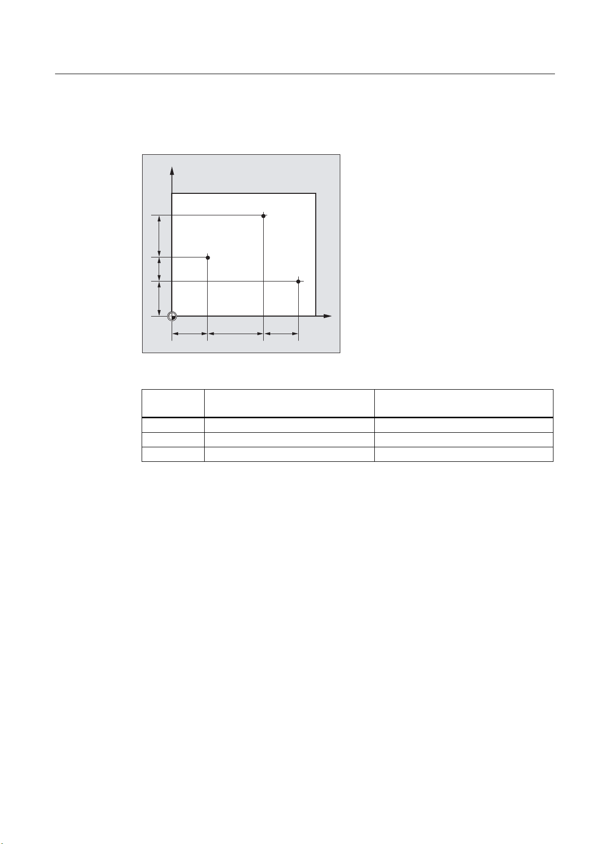
1.1.2 Cartesian coordinates
The axes in the coordinate system are assigned dimensions. In this way, it is possible to
clearly describe every point in the coordinate system and therefore every workpiece position
through the direction (X, Y and Z) and three numerical values The workpiece zero always
has the coordinates X0, Y0, and Z0.
Position specifications in the form of Cartesian coordinates
To simplify things, we will only consider one plane of the coordinate system in the following
example, the X/Y plane:
<
3
;
3
<
3
;
3
Points P1 to P4 have the following coordinates:
Position Coordinates
P1 X100 Y50
P2 X-50 Y100
P3 X-105 Y-115
P4 X70 Y-75
Fundamentals
14 Programming Manual, 03/2013, 6FC5398-1BP40-3BA1
Page 15
Fundamental Geometrical Principles
1.1 Workpiece positions
Example: Workpiece positions for turning
With lathes, one plane is sufficient to describe the contour:
;
3
3 3
3
=
Points P1 to P4 have the following coordinates:
Position Coordinates
P1 X25 Z-7.5
P2 X40 Z-15
P3 X40 Z-25
P4 X60 Z-35
Fundamentals
Programming Manual, 03/2013, 6FC5398-1BP40-3BA1
15
Page 16
Fundamental Geometrical Principles
1.1 Workpiece positions
Example: Workpiece positions for milling
For milling, the feed depth must also be described, i.e. the third coordinate (in this case Z)
must also be assigned a numerical value.
<
3
3
3
;
3
3
3
<
=
Points P1 to P3 have the following coordinates:
Position Coordinates
P1 X10 Y45 Z-5
P2 X30 Y60 Z-20
P3 X45 Y20 Z-15
Fundamentals
16 Programming Manual, 03/2013, 6FC5398-1BP40-3BA1
Page 17
Fundamental Geometrical Principles
1.1 Workpiece positions
1.1.3 Polar coordinates
Polar coordinates can be used instead of Cartesian coordinates to describe workpiece
positions. This is useful when a workpiece or part of a workpiece has been dimensioned with
radius and angle. The point from which the dimensioning starts is called the "pole".
Position specifications in the form of polar coordinates
Polar coordinates are made up of the polar radius and the polar angle.
The polar radius is the distance between the pole and the position.
The polar angle is the angle between the polar radius and the horizontal axis of the working
plane. Negative polar angles are in the clockwise direction, positive polar angles in the
counterclockwise direction.
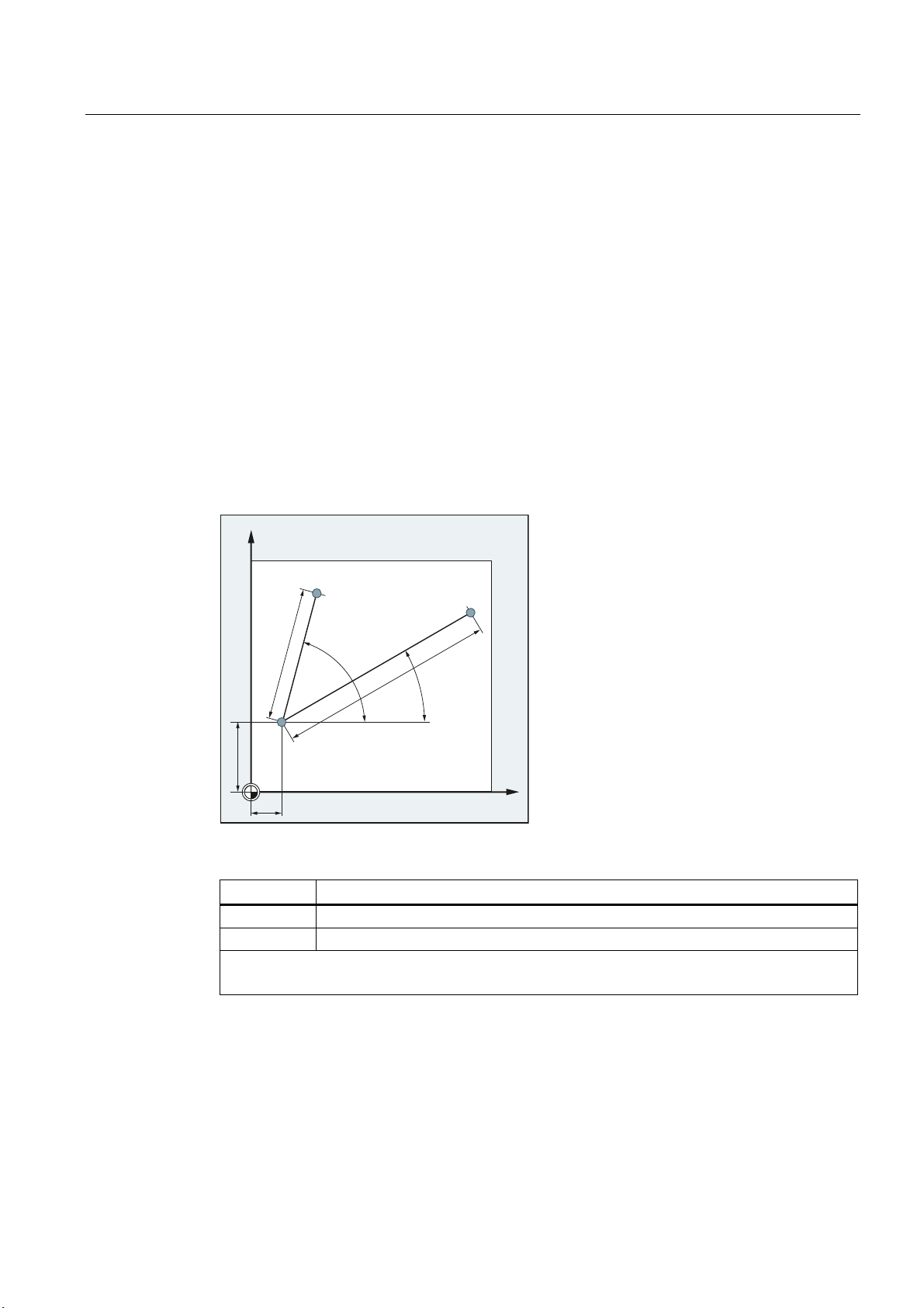
Example
<
3
3
r
3ROH
r
;
Points P1 and P2 can then be described – with reference to the pole – as follows:
Position Polar coordinates
P1 RP=100 AP=30
P2 RP=60 AP=75
RP: Polar radius
AP: Polar angle
Fundamentals
Programming Manual, 03/2013, 6FC5398-1BP40-3BA1
17
Page 18
Fundamental Geometrical Principles
1.1 Workpiece positions
1.1.4 Absolute dimensions
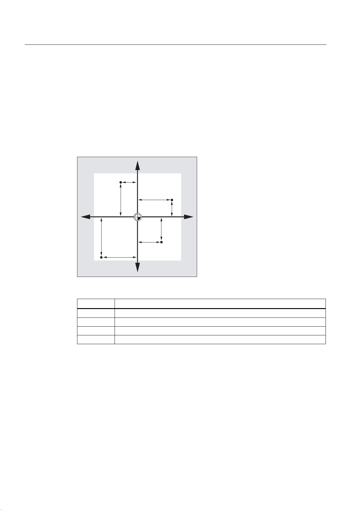
Position specifications in absolute dimensions
With absolute dimensions, all the position specifications refer to the currently valid zero
point.
Applied to tool movement this means:
the position, to which the tool is to travel.
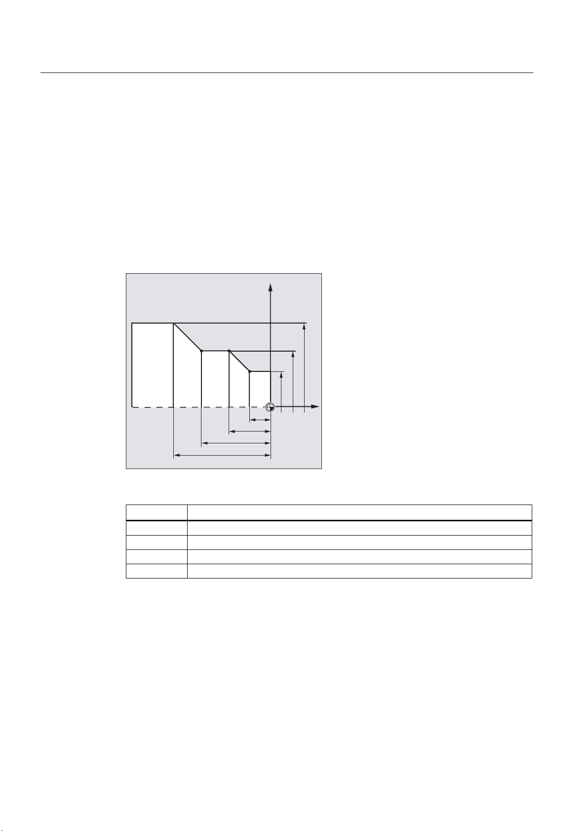
Example: Turning
;
3
3 3
3
=
In absolute dimensions, the following position specifications result for points P1 to P4:
Position Position specification in absolute dimensions
P1 X25 Z-7.5
P2 X40 Z-15
P3 X40 Z-25
P4 X60 Z-35
Fundamentals
18 Programming Manual, 03/2013, 6FC5398-1BP40-3BA1
Page 19
Fundamental Geometrical Principles
1.1 Workpiece positions
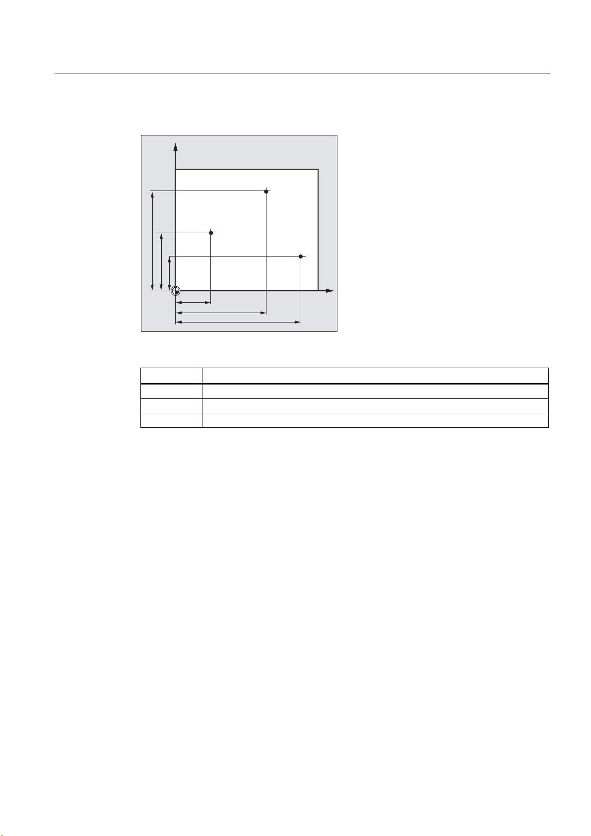
Example: Milling
<
3
3
3
In absolute dimensions, the following position specifications result for points P1 to P3:
;
Position Position specification in absolute dimensions
P1 X20 Y35
P2 X50 Y60
P3 X70 Y20
Fundamentals
Programming Manual, 03/2013, 6FC5398-1BP40-3BA1
19
Page 20
Fundamental Geometrical Principles
1.1 Workpiece positions
1.1.5 Incremental dimension
Position specifications in incremental dimensions
In production drawings, the dimensions often do not refer to a zero point, but to another
workpiece point. So that these dimensions do not have to be converted, they can be
specified in incremental dimensions. In this method of dimensional notation, a position
specification refers to the previous point.
Applied to tool movement this means:
The incremental dimensions describe the distance the tool is to travel.
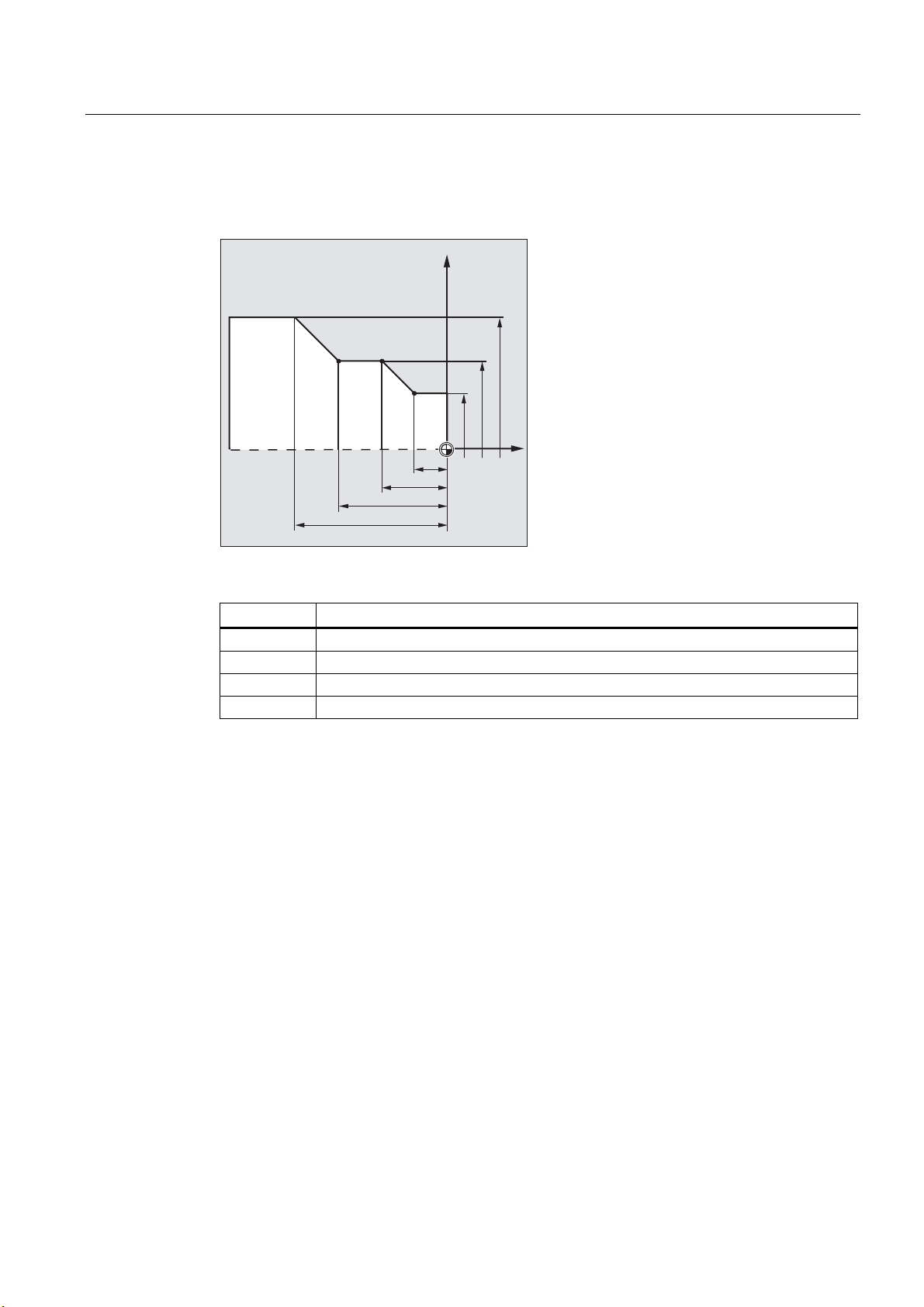
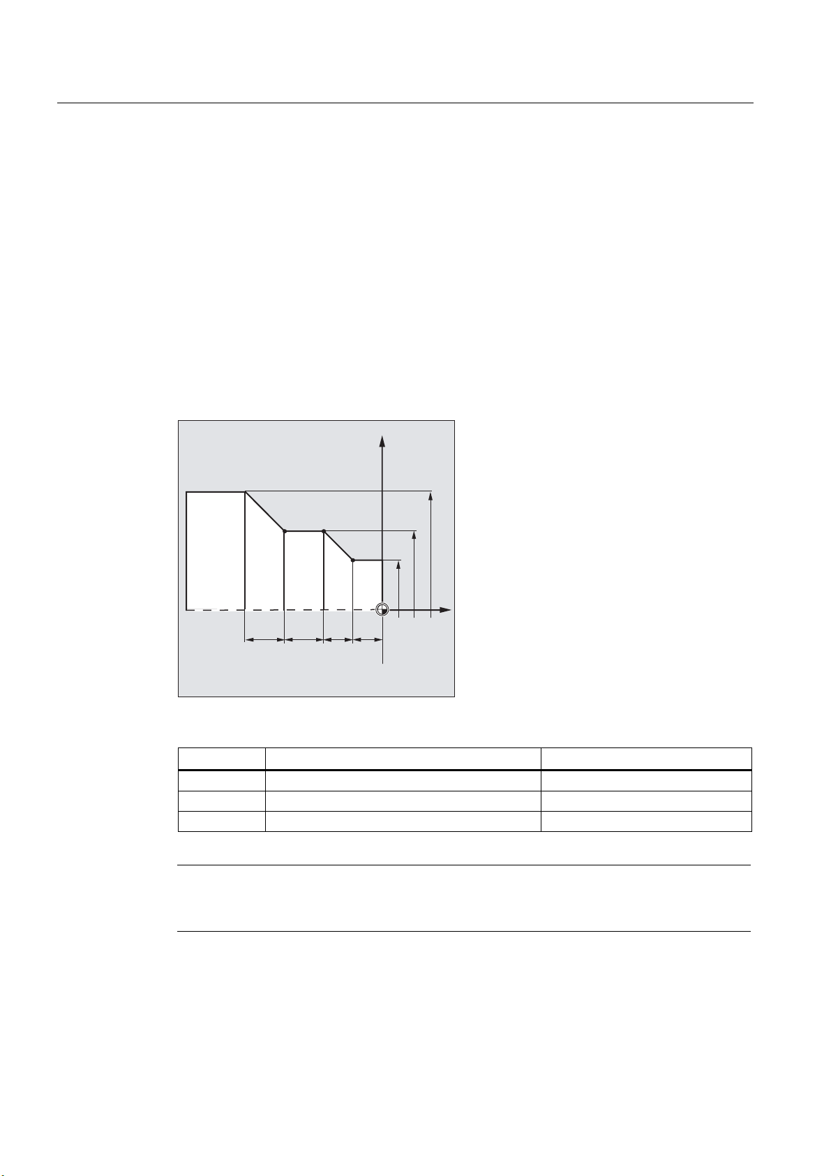
Example: Turning
;
3
3 3
3
=
In incremental dimensions, the following position specifications result for points P2 to P4:
Position Position specification in incremental dimensions The specification refers to:
P2 X15 Z-7.5 P1
P3 Z-10 P2
P4 X20 Z-10 P3
Note
With
DIAMOF or DIAM90 active, the set distance in incremental dimensions (G91) is
programmed as a radius dimension.
Fundamentals
20 Programming Manual, 03/2013, 6FC5398-1BP40-3BA1
Page 21
Fundamental Geometrical Principles
1.2 Working planes
Example: Milling
The position specifications for points P1 to P3 in incremental dimensions are:
<
3
3
In incremental dimensions, the following position specifications result for points P1 to P3:
Position Position specification in incremental
dimensions
P1 X20 Y35 Zero point
P2 X30 Y20 P1
P3 X20 Y -35 P2
1.2 Working planes
An NC program must contain information about the plane in which the work is to be
performed. Only then can the control unit calculate the correct tool offsets during the
execution of the NC program. The specification of the working plane is also relevant for
certain types of circular-path programming and polar coordinates.
3
;
The specification refers to:
Two coordinate axes define a working plane. The third coordinate axis is perpendicular to
this plane and determines the infeed direction of the tool (e.g. for 2D machining).
Fundamentals
Programming Manual, 03/2013, 6FC5398-1BP40-3BA1
21
Page 22
Fundamental Geometrical Principles
1.3 Zero points and reference points
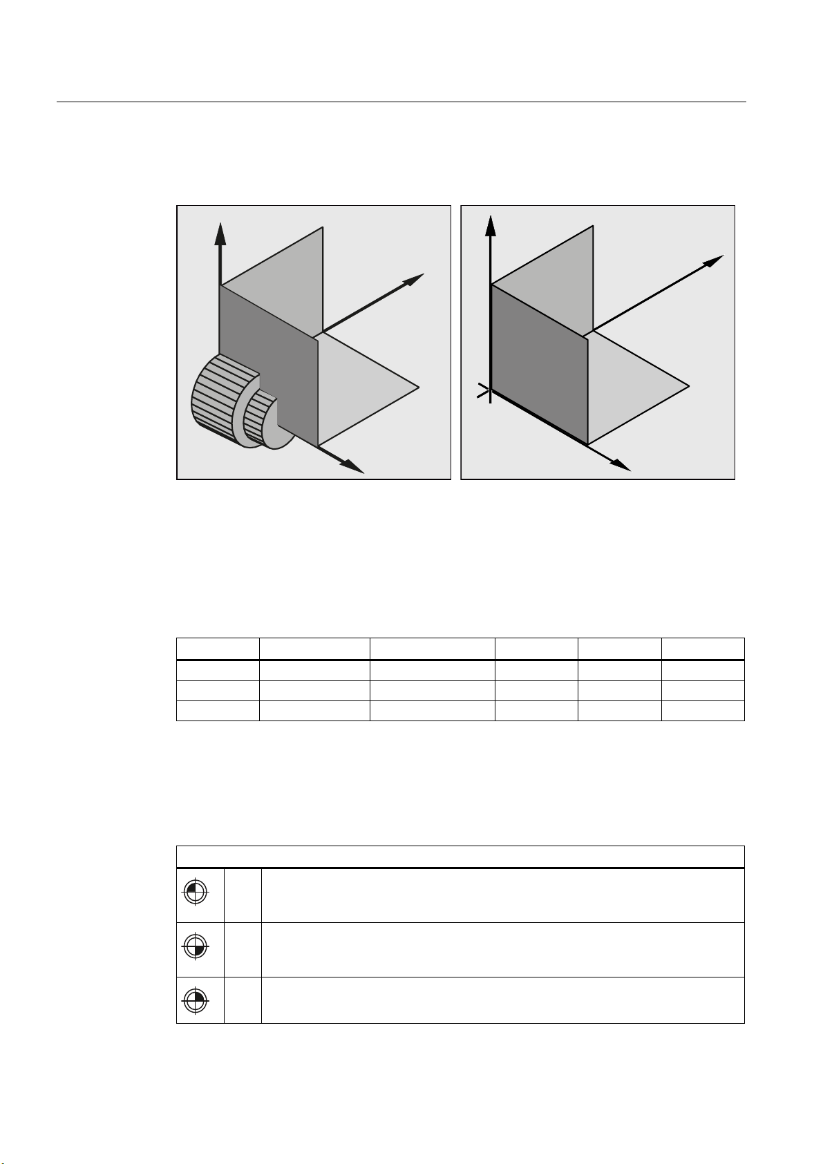
Working planes for turning/milling
<
*
*
Working planes for turning
Programming of the working planes
The working planes are defined in the NC program with the G commands G17, G18 and G19 as
follows:
*
=
=
;
*
Working planes for milling
<
*
*
;
G command Working plane Infeed direction Abscissa Ordinate Applicate
G17
G18
G19
X/Y Z X Y Z
Z/X Y Z X Y
Y/Z X Y Z X
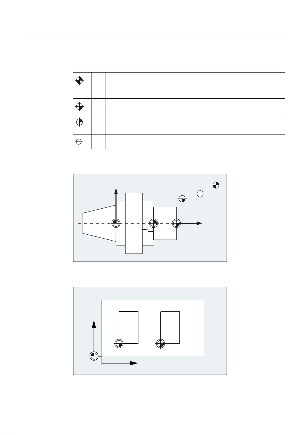
1.3 Zero points and reference points
Various zero points and reference points are defined on an NC machine:
Zero points
M Machine zero
The machine zero defines the machine coordinate system (MCS). All other reference
points refer to the machine zero.
W Workpiece zero = program zero
The workpiece zero defines the workpiece coordinate system in relation to the
machine zero.
A Blocking point
Can be the same as the workpiece zero (only for lathes).
Fundamentals
22 Programming Manual, 03/2013, 6FC5398-1BP40-3BA1
Page 23
Fundamental Geometrical Principles
1.3 Zero points and reference points
Reference points
R Reference point
Position defined by output cam and measuring system. The distance to the machine
zero M must be known so that the axis position at this point can be set exactly to this
value.
B Starting point
Can be defined by the program. The first machining tool starts here.
T Toolholder reference point
Is on the toolholder. By entering the tool lengths, the controller calculates the distance
between the tool tip and the toolholder reference point.
N Tool change point
Zero points and reference points for turning
Zero points for milling
;
%
:$0
1
=
5
<
0
Fundamentals
Programming Manual, 03/2013, 6FC5398-1BP40-3BA1
::
;
23
Page 24
Fundamental Geometrical Principles
1.4 Coordinate systems
1.4 Coordinate systems
A distinction is made between the following coordinate systems:
● Machine coordinate system (MCS) (Page 24) with the machine zero M
● Basic coordinate system (BCS) (Page 27)
● Basic zero system (BZS) (Page 29)
● Settable zero system (SZS) (Page 30)
● Workpiece coordinate system (WCS) (Page 31) with the workpiece zero W
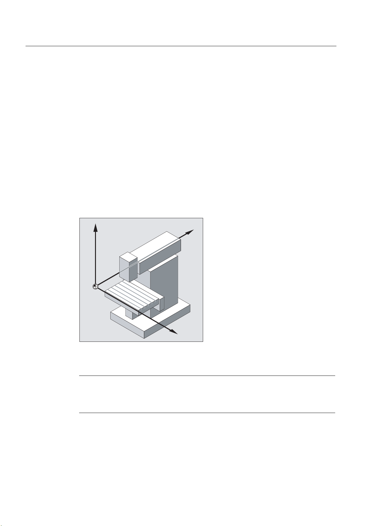
1.4.1 Machine coordinate system (MCS)
The machine coordinate system comprises all the physically existing machine axes.
Reference points and tool and pallet changing points (fixed machine points) are defined in
the machine coordinate system.
=P
0
<P
;P
If programming is performed directly in the machine coordinate system (possible with some
G functions), the physical axes of the machine respond directly. Any workpiece clamping that
is present is not taken into account.
Note
If there are various machine coordinate systems (e.g. 5-axis transformation), then an internal
transformation is used to map the machine kinematics on the coordinate system in which the
programming is performed.
Fundamentals
24 Programming Manual, 03/2013, 6FC5398-1BP40-3BA1
Page 25
Fundamental Geometrical Principles
1.4 Coordinate systems
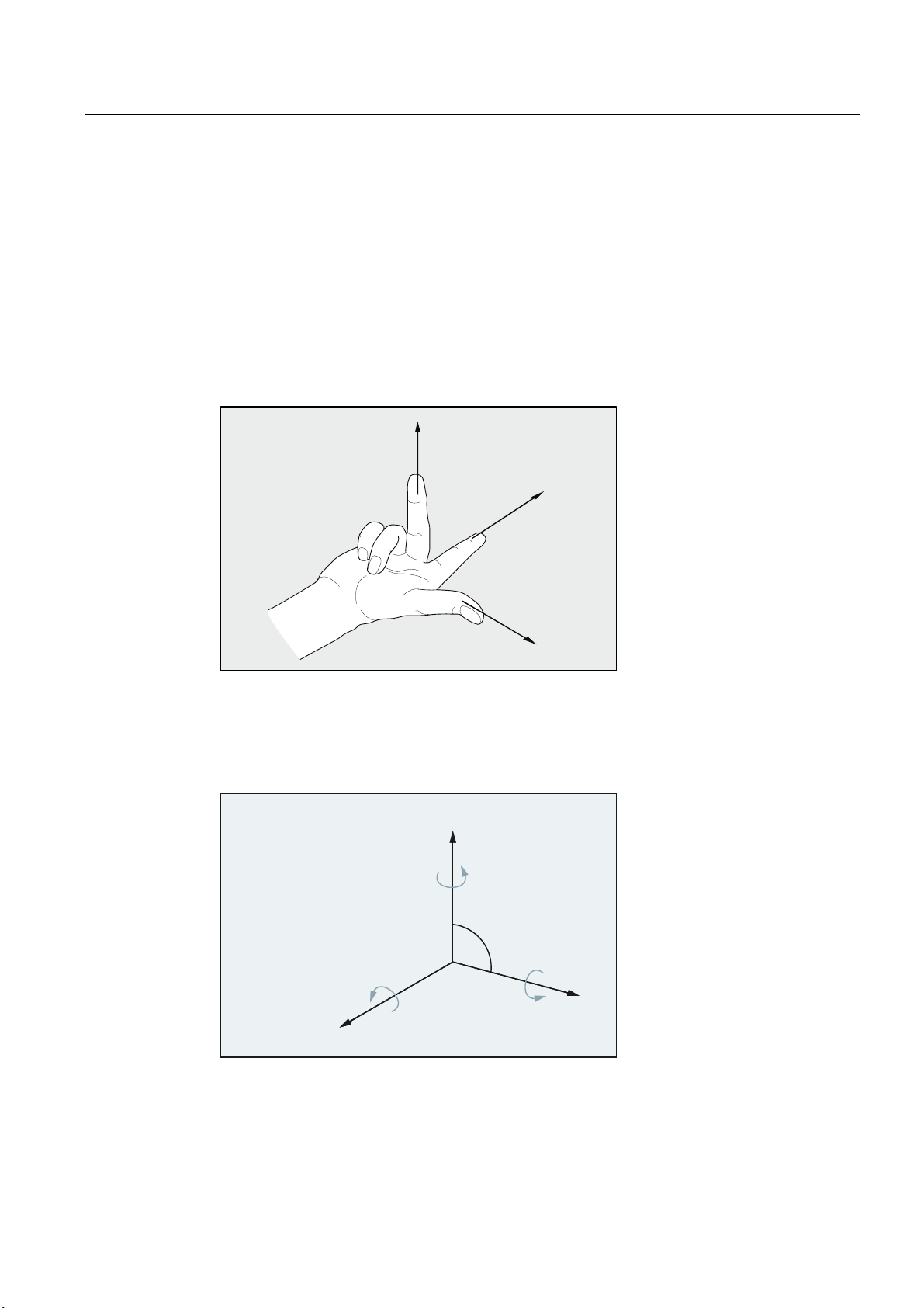
Three-finger rule
The orientation of the coordinate system relative to the machine depends on the machine
type. The axis directions follow the so-called "three-finger rule" of the right hand (according
to DIN 66217).
Seen from in front of the machine, the middle finger of the right hand points in the opposite
direction to the infeed of the main spindle. Therefore:
● the thumb points in the +X direction
● the index finger points in the +Y direction
● the middle finger points in the +Z direction
=
<
;
Figure 1-1 "Three-finger rule"
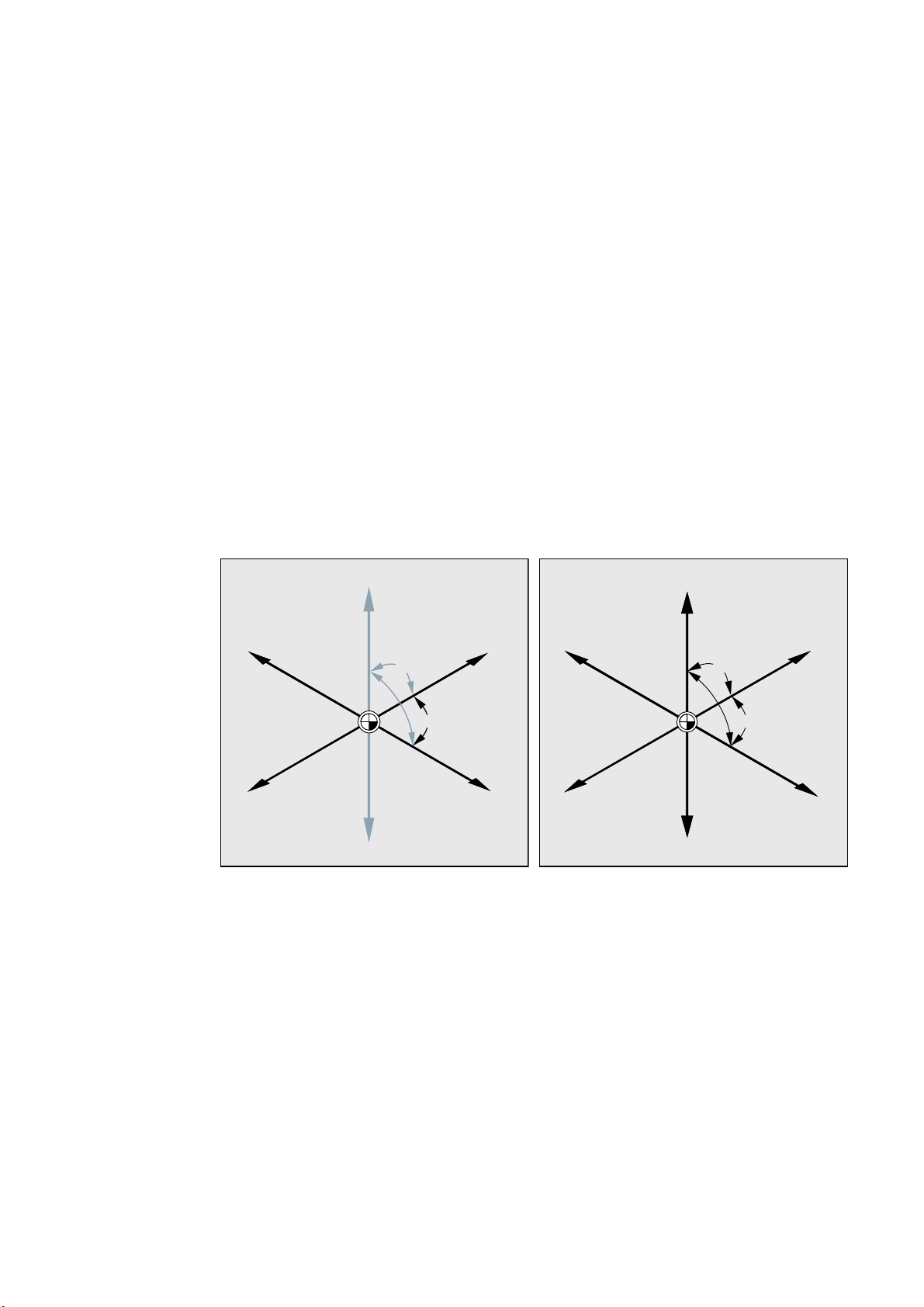
Rotary motions around the coordinate axes X, Y and Z are designated A, B and C. If the
rotary motion is in a clockwise direction when looking in the positive direction of the
coordinate axis, the direction of rotation is positive:
;<=
PXWXDOO\RUWKRJRQDO
D[HV
$%&
5RWDU\D[HV
URWDWLQJDURXQG;<=
&
<
%
r
;
$
=
Fundamentals
Programming Manual, 03/2013, 6FC5398-1BP40-3BA1
25
Page 26
Fundamental Geometrical Principles
1.4 Coordinate systems
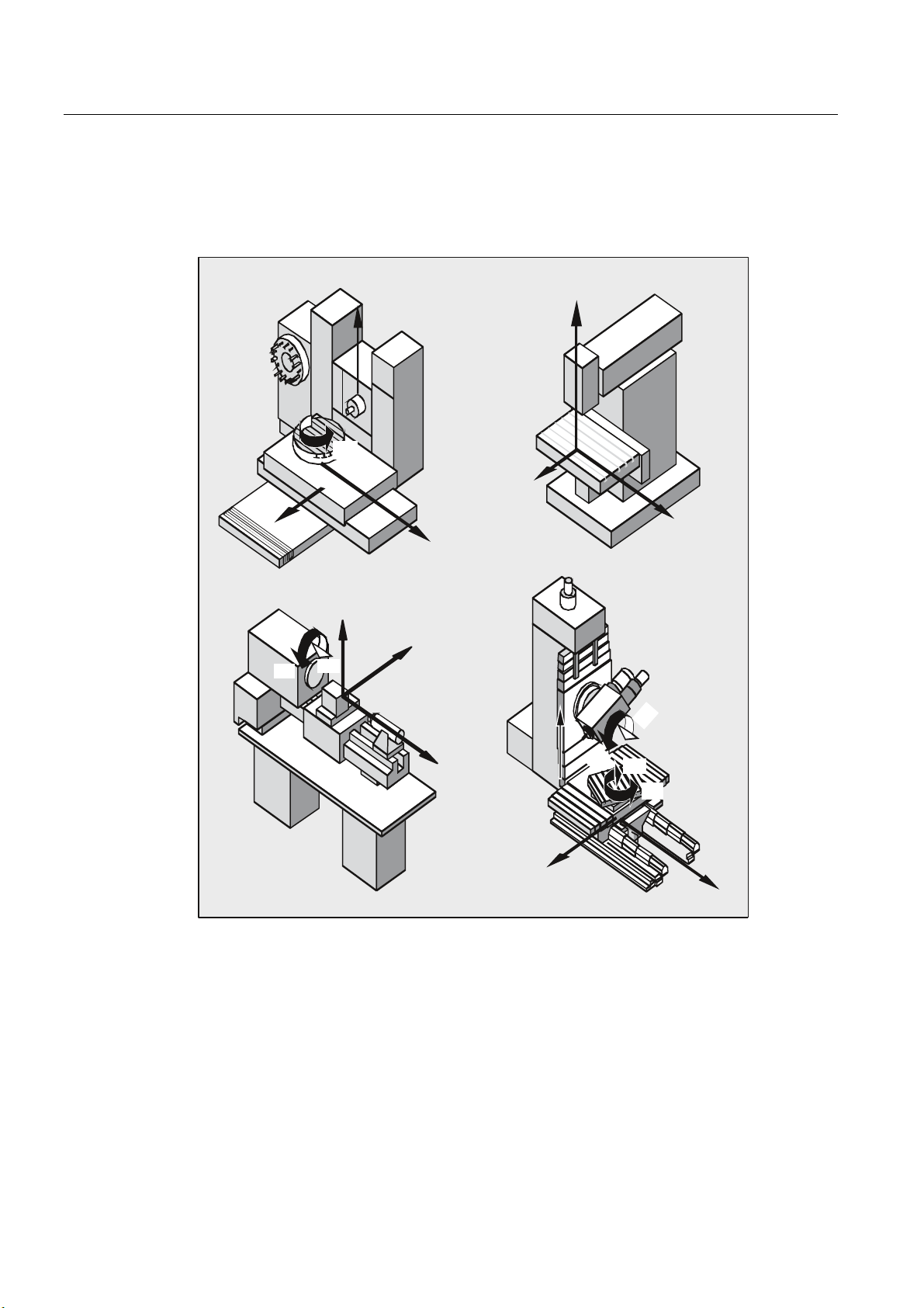
Position of the coordinate system in different machine types
The position of the coordinate system resulting from the "three-finger rule" can have a
different orientation for different machine types. Here are a few examples:
=
&
&
%
<
<
;
;
<
=
=
;
%
=
;
%
&
&
<
Fundamentals
26 Programming Manual, 03/2013, 6FC5398-1BP40-3BA1
Page 27
Fundamental Geometrical Principles
1.4 Coordinate systems
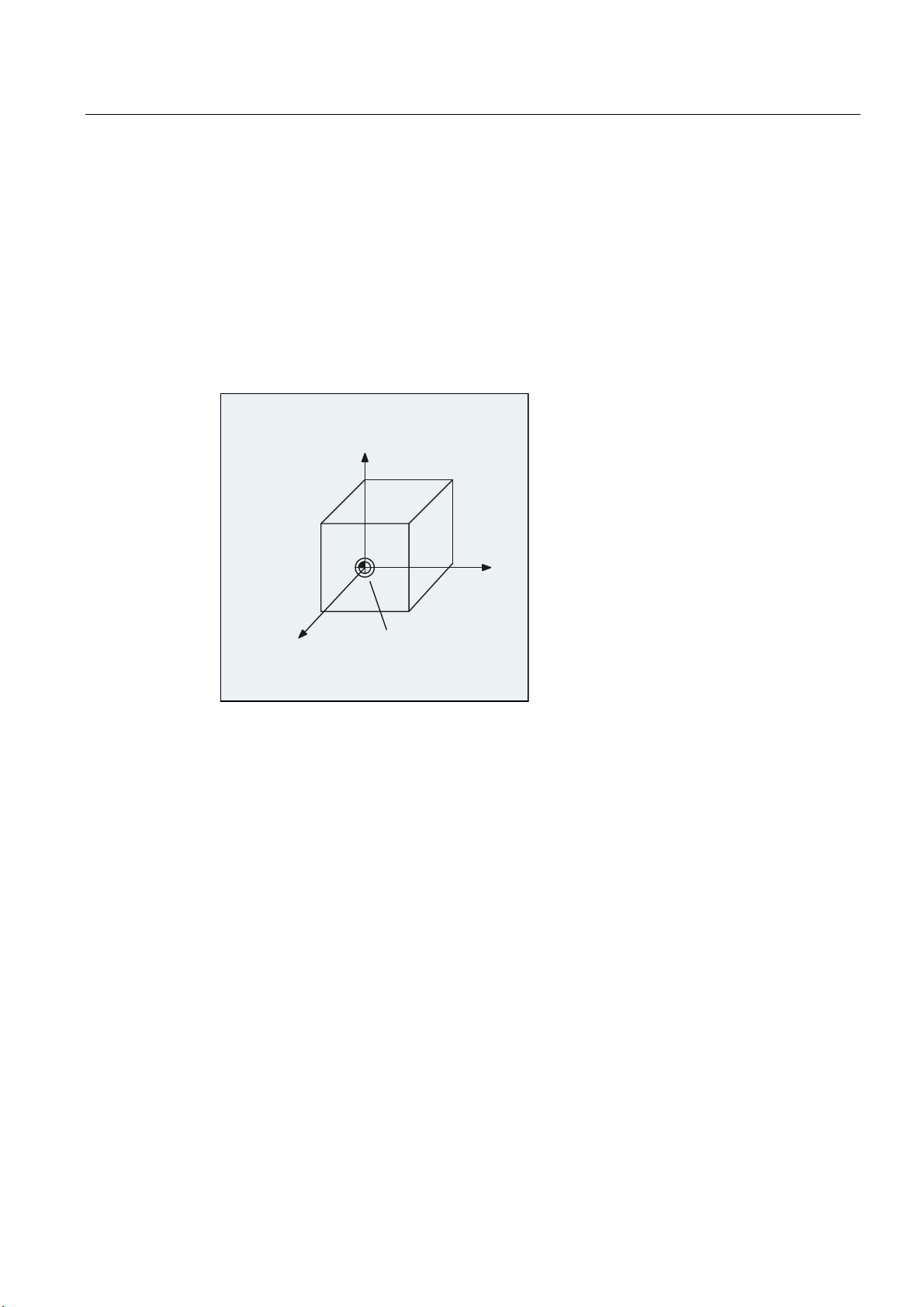
1.4.2 Basic coordinate system (BCS)
The basic coordinate system (BCS) consists of three mutually perpendicular axes (geometry
axes) as well as other special axes, which are not interrelated geometrically.
Machine tools without kinematic transformation
BCS and MCS always coincide when the BCS can be mapped onto the MCS without
kinematic transformation (e.g. 5-axis transformation, TRANSMIT/TRACYL/TRAANG).
On such machines, machine axes and geometry axes can have the same names.
<
0DFKLQH
FRRUGLQDWH
V\VWHP %&6
=
Figure 1-2 MCS = BCS without kinematic transformation
0DFKLQH]HURSRLQW
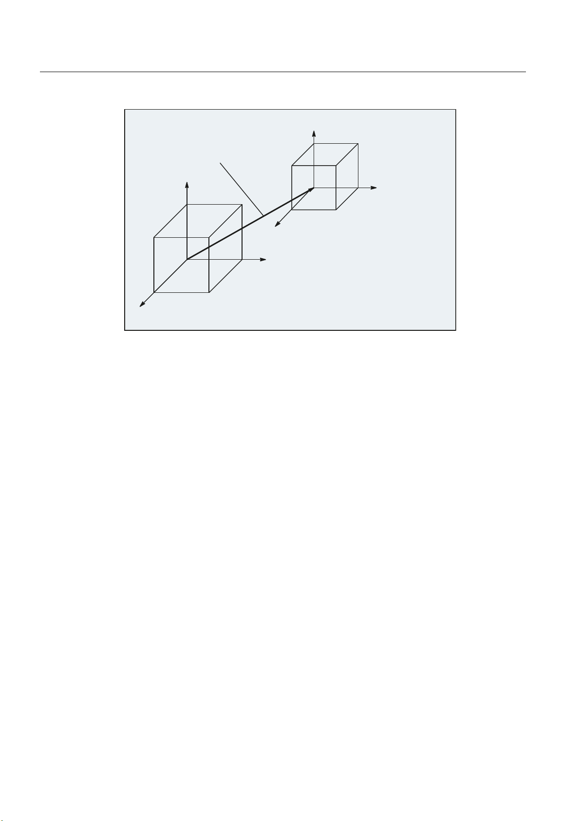
Machine tools with kinematic transformation
BCS and MCS do not coincide when the BCS is mapped onto the MCS with kinematic
transformation (e.g. 5-axis transformation, TRANSMIT/TRACYL/TRAANG).
On such machines the machine axes and geometry axes must have different names.
;
Fundamentals
Programming Manual, 03/2013, 6FC5398-1BP40-3BA1
27
Page 28
Fundamental Geometrical Principles
1.4 Coordinate systems
<
%&6
.LQHPDWLF
WUDQVIRUPDWLRQ
<
0&6
;
%&6
Figure 1-3 Kinematic transformation between the MCS and BCS
Machine kinematics
The workpiece is always programmed in a two or three dimensional, right-angled coordinate
system (WCS). However, such workpieces are being programmed ever more frequently on
machine tools with rotary axes or linear axes not perpendicular to one another. Kinematic
transformation is used to represent coordinates programmed in the workpiece coordinate
system (rectangular) in real machine movements.
References
Function Manual Expansion Functions; M1: Kinematic transformation
=
%&6
;
0&6
%DVLFFRRUGLQDWHV\VWHP%&6
0DFKLQHFRRUGLQDWHV\VWHP0&6
=
0&6
Function Manual, Special Functions; F2: Multi-axis transformations
Fundamentals
28 Programming Manual, 03/2013, 6FC5398-1BP40-3BA1
Page 29
Fundamental Geometrical Principles
1.4 Coordinate systems
1.4.3 Basic zero system (BZS)
The basic zero system (BZS) is the basic coordinate system with a basic offset.
<
%DVLFRIIVHW
<
;
%DVLF]HURV\VWHP%=6
=
;
%DVLFFRRUGLQDWHV\VWHP%&6
=
Basic offset
References
The basic offset describes the coordinate transformation between BCS and BZS. It can be
used, for example, to define the palette window zero.
The basic offset comprises:
● External zero offset
● DRF offset
● Overlaid movement
● Chained system frames
● Chained basic frames
Function Manual, Basic Functions; Axes, Coordinate Systems, Frames (K2)
Fundamentals
Programming Manual, 03/2013, 6FC5398-1BP40-3BA1
29
Page 30
Fundamental Geometrical Principles
1.4 Coordinate systems
1.4.4 Settable zero system (SZS)
Settable zero offset
The "settable zero system" (SZS) results from the basic zero system (BZS) through the
settable zero offset.
Settable zero offsets are activated in the NC program with the G commands
G505...G599 as follows:
<
**
<
;
=
;
%DVLF]HURV\VWHP%=6
=
6HWWDEOH
]HURV\VWHP6=6
G54...G57 and
If no programmable coordinate transformations (frames) are active, then the "settable zero
system" is the workpiece coordinate system (WCS).
Programmable coordinate transformations (frames)
Sometimes it is useful or necessary within an NC program, to move the originally selected
workpiece coordinate system (or the "settable zero system") to another position and, if
required, to rotate it, mirror it and/or scale it. This is performed using programmable
coordinate transformations (frames).
See Section: "Coordinate transformations (frames)"
Fundamentals
30 Programming Manual, 03/2013, 6FC5398-1BP40-3BA1
Note
Programmable coordinate transformations (frames) always refer to the "settable zero
system".
Page 31

Fundamental Geometrical Principles
1.4 Coordinate systems
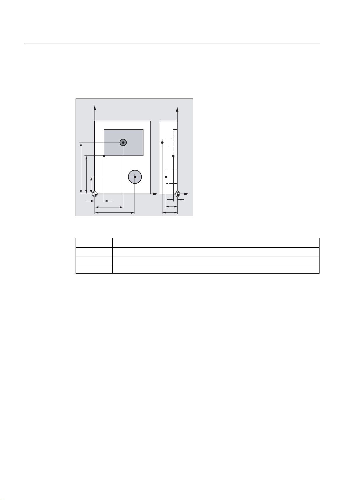
1.4.5 Workpiece coordinate system (WCS)
The geometry of a workpiece is described in the workpiece coordinate system (WCS). In
other words, the data in the NC program refers to the workpiece coordinate system.
The workpiece coordinate system is always a Cartesian coordinate system and assigned to
a specific workpiece.
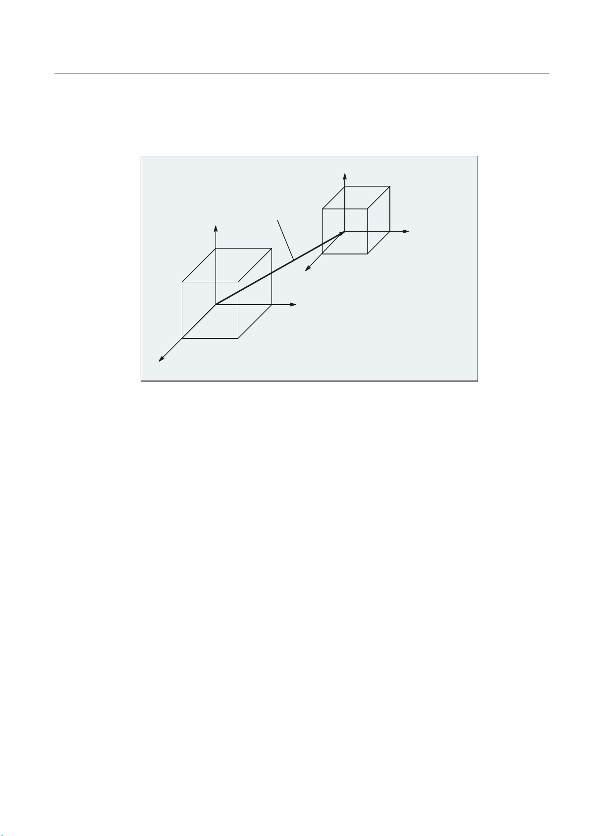
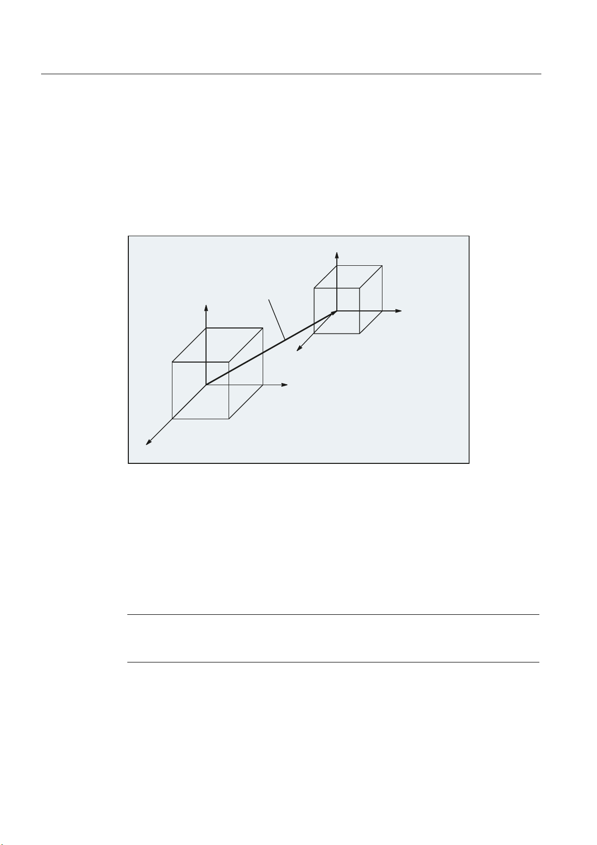
1.4.6 What is the relationship between the various coordinate systems?
The example in the following figure should help clarify the relationships between the various
coordinate systems:
3URJUDPPDEOH
FRRUGLQDWHWUDQVIRUPDWLRQ
]
6=6
]
]
\
:&6
[
\
[
]
\
:&6
[
\
:RUNSLHFH
[
3DOOHW
:RUNSLHFH
]
0&6
%&6
%DVLFRIIVHW
]
6HWWDEOHZRUNRIIVHW
%=6
6HWWDEOH
ZRUNRIIVHW
\
*
\
*
6=6
[
[
3URJUDPPDEOH
FRRUGLQDWHWUDQVIRUPDWLRQ
① A kinematic transformation is not active, i.e. the machine coordinate system and the basic
coordinate system coincide.
② The basic zero system (BZS) with the pallet zero result from the basic offset.
③ The "settable zero system" (SZS) for Workpiece 1 or Workpiece 2 is specified by the settable
zero offset G54 or G55.
④ The workpiece coordinate system (WCS) results from programmable coordinate
transformation.
Fundamentals
Programming Manual, 03/2013, 6FC5398-1BP40-3BA1
31
Page 32

Fundamental Geometrical Principles
1.4 Coordinate systems
Fundamentals
32 Programming Manual, 03/2013, 6FC5398-1BP40-3BA1
Page 33

Fundamental Principles of NC Programming
2.1 Name of an NC program
Rules for program names
Note
DIN 66025 is the guideline for NC programming.
Each NC program has a different name; the name can be chosen freely during program
creation, taking the following conditions into account:
● The name should not have more than 24 characters as only the first 24 characters of a
program name are displayed on the NC.
● Permissible characters are:
– Letters: A...Z, a...z
2
– Numbers: 0...9
– Underscores: _
● The first two characters should be:
– Two letters
Or
– An underscore and a letter
If this condition is satisfied, then an NC program can be called as subprogram from
another program just by specifying the program name. However, if the program name
starts with a number then the subprogram call is only possible via the
Examples:
● _MPF100
● SHAFT
● SHAFT_2
CALL statement.
Fundamentals
Programming Manual, 03/2013, 6FC5398-1BP40-3BA1
33
Page 34

Fundamental Principles of NC Programming
2.1 Name of an NC program
Note
To avoid complications with Windows applications, avoid using the following program
names:
CON, PRN, AUX, NUL
COM1, COM2, COM3, COM4, COM5, COM6, COM7, COM8, COM9
LPT1, LPT2, LPT3, LPT4, LPT5, LPT6, LPT7, LPT8, LPT9
For further restrictions on the program names, see "Identifier (Page 402)".
Files in punch tape format
Externally created program files that are read into the NC via the V.24 interface must be
present in punch tape format.
The following additional rules apply for the name of a file in punch tape format:
● The program name must begin with "%":
References
%<Name>
● The program name must have a 3-character identifier:
%<Name>_xxx
Examples:
● %_N_SHAFT123_MPF
● %Flange3_MPF
Note
The name of a file stored internally in the NC memory starts with "_N_".
For further information on transferring, creating and saving part programs, see the Operating
Manual.
Fundamentals
34 Programming Manual, 03/2013, 6FC5398-1BP40-3BA1
Page 35

Fundamental Principles of NC Programming
2.2 Structure and contents of an NC program
2.2 Structure and contents of an NC program
2.2.1 Blocks and block components
Blocks
An NC program consists of a sequence of NC blocks. Each block contains the data for the
execution of a step in the workpiece machining.
Block components
NC blocks consist of the following components:
● Commands (statements) according to DIN 66025
● Elements of the NC high-level language
Commands according to DIN 66025
The commands according to DIN 66025 consist of an address character and a digit or
sequence of digits representing an arithmetic value.
Address character (address)
The address character (generally a letter) defines the meaning of the command.
Examples:
Address character Meaning
G G function (preparatory function)
X Position data for the X axis
S Spindle speed
Digit sequence
The digit sequence is the value assigned to the address character. The sequence of digits
can contain a sign and decimal point. The sign always appears between the address letter
and the sequence of digits. Positive signs (+) and leading zeroes (0) do not have to be
specified.
$GGUHVV
*
$GGUHVV
'LJLWVHTXHQFH
'LJLWVHTXHQFH
; 6
$GGUHVV
'LJLWVHTXHQFH
%ORFN
Fundamentals
Programming Manual, 03/2013, 6FC5398-1BP40-3BA1
35
Page 36

Fundamental Principles of NC Programming
2.2 Structure and contents of an NC program
Elements of the NC high-level language
As the command set according to DIN 66025 is no longer adequate for the programming of
complex machining sequences in modern machine tools, it has been extended by the
elements of the NC high-level language.
These include, for example:
● Commands of the NC high-level language
In contrast to the commands according to DIN 66025, the commands of the NC high-level
language consist of several address letters, e.g.
–
OVR for speed override
–
SPOS for spindle positioning
● Identifiers (defined names) for:
– System variables
– User-defined variables
– Subprograms
– Keywords
– Jump markers
– Macros
Note
An identifier must be unique and cannot be used for different objects.
● Comparison operators
● Logic operators
● Arithmetic functions
● Check structures
References:
Programming Manual, Job Planning; Section: "Flexible NC programming"
Effectiveness of commands
Commands are either modal or non-modal:
● Modal
Modal commands retain their validity with the programmed value (in all following blocks)
until:
– A new value is programmed under the same command
– A command is programmed that revokes the effect of the previously valid command
● Non-modal
Non-modal commands only apply for the block in which they were programmed.
Fundamentals
36 Programming Manual, 03/2013, 6FC5398-1BP40-3BA1
Page 37

Fundamental Principles of NC Programming
2.2 Structure and contents of an NC program
End of program
The last block in the execution sequence contains a special word for the end of program: M2,
M17 or M30.
2.2.2 Block rules
Start of block
NC blocks can be identified at the start of the block by block numbers. These consist of the
character "N" and a positive integer, e.g.
N40 ...
The order of the block numbers is arbitrary, however, block numbers in rising order are
recommended.
Note
Block numbers must be unique within a program in order to achieve an unambiguous result
when searching.
End of block
Block length
A block ends with the character LF (LINE FEED = new line).
Note
The LF character does not have to be written. It is generated automatically by the line
change.
A block can contain a maximum of 512 characters (including the comment and end-of-block
character LF).
Note
Three blocks of up to 66 characters each are normally displayed in the current block display
on the screen. Comments are also displayed. Messages are displayed in a separate
message window.
Fundamentals
Programming Manual, 03/2013, 6FC5398-1BP40-3BA1
37
Page 38

Fundamental Principles of NC Programming
2.2 Structure and contents of an NC program
Order of the statements
In order to keep the block structure as clear as possible, the statements in a block should be
arranged in the following order:
N… G… X… Y… Z… F… S… T… D… M… H…
Address Meaning
N
G
X,Y,Z
F
S
T
D
M
H
Note
Address of block number
Preparatory function
Positional data
Feedrate
Spindle speed
Tool
Tool offset number
Additional function
Auxiliary function
Certain addresses can be used repeatedly within a block, e.g.
G…, M…, H…
2.2.3 Value assignments
Values can be assigned to the addresses. The following rules apply:
● An "=" sign must be inserted between the address and the value if:
– The address comprises more than one letter
– The value includes more than one constant.
The "="-sign can be omitted if the address is a single letter and the value consists of only
one constant.
● Signs are permitted.
● Separators are permitted after the address letter.
Examples:
X10
X1=10
X=10*(5+SIN(37.5))
Note
Value assignment (10) to address X, "=" not required
Value assignment (10) to address (X) with numeric extension (1),
"=" required
Value assignment by means of a numeric expression, "=" required
A numeric extension must always be followed by one of the special characters "=", "(", "[",
")", "]", ",", or an operator, in order to distinguish an address with numeric extension from an
address letter with a value.
Fundamentals
38 Programming Manual, 03/2013, 6FC5398-1BP40-3BA1
Page 39

Fundamental Principles of NC Programming
2.2 Structure and contents of an NC program
2.2.4 Comments
To make an NC program easier to understand, comments can be added to the NC blocks.
A comment is at the end of a block and is separated from the program section of the NC
block by a semicolon (";").
Example 1:
Program code Comments
N10 G1 F100 X10 Y20 ; Comment to explain the NC block
Example 2:
Program code Comment
N10 ; Company G&S, order no. 12A71
N20 ; Program written by H. Smith, Dept. TV 4 ;on November
21, 1994
N50 ; Section no. 12, housing for submersible pump type TP23A
Note
Comments are stored and appear in the current block display when the program is running.
2.2.5 Skipping blocks
NC blocks, which are not to be executed in every program pass (e.g. execute a trial program
run), can be skipped.
Programming
Blocks, which are to be skipped are marked with an oblique "/" in front of the block number.
Several consecutive blocks can also be skipped. The statements in the skipped blocks are
not executed; the program continues with the next block, which is not skipped.
Fundamentals
Programming Manual, 03/2013, 6FC5398-1BP40-3BA1
39
Page 40

Fundamental Principles of NC Programming
2.2 Structure and contents of an NC program
Example:
1
1
1
1
1
1
1
1
1
1
1
1
3URJUDPH[HFXWLRQ
Program code Comment
N10 ; Is executed
/N20 … ; Skipped
N30 … ; Is executed
/N40 … ; Skipped
N70 … ; Is executed
Skip levels
Blocks can be assigned to skip levels (max. 10), which can be activated via the user
interface.
Programming is performed by assigning a forward slash, followed by the number of the skip
level. Only one skip level can be specified for each block.
Example:
Program code Comment
/ ... ; Block is skipped (1st skip level)
/0 ... ; Block is skipped (1st skip level)
/1 N010... ; Block is skipped (2nd skip level)
/2 N020... ; Block is skipped (3rd skip level)
...
/7 N100... ; Block is skipped (8th skip level)
/8 N080... ; Block is skipped (9th skip level)
/9 N090... ; Block is skipped (10th skip level)
Fundamentals
40 Programming Manual, 03/2013, 6FC5398-1BP40-3BA1
Page 41

Fundamental Principles of NC Programming
2.2 Structure and contents of an NC program
Note
The number of skip levels that can be used depends on a display machine data item.
Note
System and user variables can also be used in conditional jumps in order to control program
execution.
Fundamentals
Programming Manual, 03/2013, 6FC5398-1BP40-3BA1
41
Page 42

Fundamental Principles of NC Programming
2.2 Structure and contents of an NC program
Fundamentals
42 Programming Manual, 03/2013, 6FC5398-1BP40-3BA1
Page 43

Creating an NC program
3.1 Basic procedure
The programming of the individual operation steps in the NC language generally represents
only a small proportion of the work in the development of an NC program.
Programming of the actual instructions should be preceded by the planning and preparation
of the operation steps. The more accurately you plan in advance how the NC program is to
be structured and organized, the faster and easier it will be to produce a complete program,
which is clear and free of errors. Clearly structured programs are especially advantageous
when changes have to be made later.
As every part is not identical, it does not make sense to create every program in the same
way. However, the following procedure has shown itself to be suitable in the most cases.
Procedure
1. Prepare the workpiece drawing
– Define the workpiece zero
– Draw the coordinate system
3
– Calculate any missing coordinates
2. Define the machining sequence
– Which tools are used when and for the machining of which contours?
– In which order will the individual elements of the workpiece be machined?
– Which individual elements are repeated (possibly also rotated) and should be stored in
a subroutine?
– Are there contour sections in other part programs or subroutines that could be used
for the current workpiece?
– Where are zero offsets, rotating, mirroring and scaling useful or necessary (frame
concept)?
Fundamentals
Programming Manual, 03/2013, 6FC5398-1BP40-3BA1
43
Page 44

Creating an NC program
3.2 Available characters
3. Create a machining plan
Define all machining operations step-by-step, e.g.
– Rapid traverse movements for positioning
– Tool change
– Define the machining plane
– Retraction for checking
– Switch spindle, coolant on/off
– Call up tool data
– Feed
– Path correction
– Approaching the contour
– Retraction from the contour
– etc.
4. Compile machining steps in the programming language
– Write each individual step as an NC block (or NC blocks).
5. Combine the individual steps into a program
3.2 Available characters
The following characters are available for writing NC programs:
● Upper-case characters:
A, B, C, D, E, F, G, H, I, J, K, L, M, N,(O),P, Q, R, S, T, U, V, W, X, Y, Z
● Lower-case characters:
a, b, c, d, e, f, g, h, i, j, k, l, m, n, o, p, q, r, s, t, u, v, w, x, y, z
● Numbers:
0, 1, 2, 3, 4, 5, 6, 7, 8, 9
● Special characters:
See the table below.
Special characters Meaning
% Program start character (used only for writing programs on an external PC)
( For bracketing parameters or expressions
) For bracketing parameters or expressions
[ For bracketing addresses or indexes
] For bracketing addresses or indexes
< Less than
Fundamentals
44 Programming Manual, 03/2013, 6FC5398-1BP40-3BA1
Page 45

Creating an NC program
3.3 Program header
Special characters Meaning
> Greater than
: Main block, end of label, chain operator
= Assignment, part of equation
/ Division, block suppression
* Multiplication
+ Addition
- Subtraction, minus sign
" Double quotation marks, identifier for character string
' Single quotation marks, identifier for special numerical values: hexadecimal,
binary
$ System variable identifiers
s_ Underscore, belonging to letters
? Reserved
! Reserved
. Decimal point
, Comma, parameter separator
; Comment start
& Format character, same effect as space character
LF End of block
Tab character Separator
Blank Separator (blank)
Note
Take care to differentiate between the letter "O" and the digit "0".
Note
No distinction is made between upper- and lower-case characters (exception: Tool call).
Note
Non-printable special characters are treated like blanks.
3.3 Program header
The NC blocks that are placed in front of the actual motion blocks for the machining of the
workpiece contour, are called the program header.
The program header contains information/statements regarding:
● Tool change
● Tool offsets
Fundamentals
Programming Manual, 03/2013, 6FC5398-1BP40-3BA1
45
Page 46

Creating an NC program
3.3 Program header
● Spindle motion
● Feed control
● Geometry settings (zero offset, selection of the working plane)
Program header for turning
The following example shows the typical structure of an NC program header for turning:
Program code Comment
N10 G0 G153 X200 Z500 T0 D0 ; Retract toolholder before tool turret is
rotated.
N20 T5 ; Swing in tool 5.
N30 D1 ; Activate cutting edge data record of the
tool.
N40 G96 S300 LIMS=3000 M4 M8 ; Constant cutting rate (Vc) = 300 m/min, speed
limitation = 3000 rpm, direction of rotation
counterclockwise, cooling on.
N50 DIAMON ; X axis will be programmed in diameter.
N60 G54 G18 G0 X82 Z0.2 ; Call zero offset and working plane, approach
starting position.
...
Program header for milling
The following example shows the typical structure of an NC program header for milling:
Program code Comment
N10 T="SF12" ; Alternative: T123
N20 M6 ; Trigger tool change
N30 D1 ; Activate cutting edge data record of the tool
N40 G54 G17 ; Zero offset and working plane
N50 G0 X0 Y0 Z2 S2000 M3 M8 ; Approach to the workpiece, spindle and
...
If tool orientation / coordinate transformation is being used, any transformations still active
should be deleted at the start of the program:
Program code Comment
N10 CYCLE800() ; Resetting of the swiveled plane
N20 TRAFOOF ; Resetting of TRAORI, TRANSMIT, TRACYL, ...
...
coolant on
Fundamentals
46 Programming Manual, 03/2013, 6FC5398-1BP40-3BA1
Page 47

Creating an NC program
3.4 Program examples
3.4 Program examples
3.4.1 Example 1: First programming steps
Program example 1 is to be used to perform and test the first programming steps on the NC.
Procedure
1. Create a new part program (name)
2. Edit the part program
3. Select the part program
4. Activate single block
5. Start the part program
References:
Operating Manual for the existing user interface
Note
In order that the program can run on the machine, the machine data must have been set
appropriately (→ machine manufacturer!).
Note
Alarms can occur during program verification. These alarms have to be reset first.
Program example 1
Program code Comment
N10 MSG("THIS IS MY NC PROGRAM") ; Message "THIS IS MY NC PROGRAM"
N20 F200 S900 T1 D2 M3 ;Feedrate, spindle, tool, tool offset,
N30 G0 X100 Y100 ; Approach position in rapid traverse
N40 G1 X150 ; Rectangle with feedrate, straight
N50 Y120 ; Straight line in Y
N60 X100 ; Straight line in X
N70 Y100 ; Straight line in Y
N80 G0 X0 Y0 ; Retraction in rapid traverse
N100 M30 ; End of block
displayed in the alarm line
spindle clockwise
line in X
Fundamentals
Programming Manual, 03/2013, 6FC5398-1BP40-3BA1
47
Page 48
Creating an NC program
3.4 Program examples
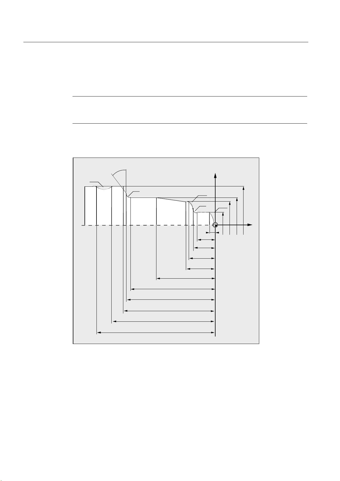
3.4.2 Example 2: NC program for turning
Program example 2 is intended for the machining of a workpiece on a lathe. It contains
radius programming and tool radius compensation.
Dimension drawing of the workpiece
Note
In order that the program can run on the machine, the machine data must have been set
appropriately (→ machine manufacturer!).
5
r
5
5
5
;
5
=
Figure 3-1 Top view
Fundamentals
48 Programming Manual, 03/2013, 6FC5398-1BP40-3BA1
Page 49

Creating an NC program
3.4 Program examples
Program example 2
Program code Comment
N5 G0 G53 X280 Z380 D0 ; Starting point
N10 TRANS X0 Z250 ; Zero offset
N15 LIMS=4000 ; Speed limitation (G96)
N20 G96 S250 M3 ; Select constant cutting rate
N25 G90 T1 D1 M8 ; Select tool selection and offset
N30 G0 G42 X-1.5 Z1 ; Set tool with tool radius compensation
N35 G1 X0 Z0 F0.25
N40 G3 X16 Z-4 I0 K-10 ; Turn radius 10
N45 G1 Z-12
N50 G2 X22 Z-15 CR=3 ; Turn radius 3
N55 G1 X24
N60 G3 X30 Z-18 I0 K-3 ; Turn radius 3
N65 G1 Z-20
N70 X35 Z-40
N75 Z-57
N80 G2 X41 Z-60 CR=3 ; Turn radius 3
N85 G1 X46
N90 X52 Z-63
N95 G0 G40 G97 X100 Z50 M9 ; Deselect tool radius compensation and approach
tool change location
N100 T2 D2 ; Call tool and select offset
N105 G96 S210 M3 ; Select constant cutting rate
N110 G0 G42 X50 Z-60 M8 ; Set tool with tool radius compensation
N115 G1 Z-70 F0.12 ; Turn diameter 50
N120 G2 X50 Z-80 I6.245 K-5 ; Turn radius 8
N125 G0 G40 X100 Z50 M9 ; Retract tool and deselect tool radius
compensation
N130 G0 G53 X280 Z380 D0 M5 ; Approach tool change location
N135 M30 ; End of program
Fundamentals
Programming Manual, 03/2013, 6FC5398-1BP40-3BA1
49
Page 50

Creating an NC program
3.4 Program examples
3.4.3 Example 3: NC program for milling
Program example 3 is intended for the machining of a workpiece on a vertical milling
machine. It contains surface and side milling as well as drilling.
Dimension drawing of the workpiece
Note
In order that the program can run on the machine, the machine data must have been set
appropriately (→ machine manufacturer!).
ෘ ෘ
Figure 3-2 Side view
[r
5
r
5
Figure 3-3 Top view
Fundamentals
50 Programming Manual, 03/2013, 6FC5398-1BP40-3BA1
Page 51

Creating an NC program
3.4 Program examples
Program example 3
Program code Comment
N10 T="PF60" ; Preselection of the tool with
name PF60.
N20 M6 ; Load the tool into the spindle.
N30 S2000 M3 M8 ; Speed, direction of rotation,
cooling on.
N40 G90 G64 G54 G17 G0 X-72 Y-72 ; Basic settings of the
geometry and approach
starting point.
N50 G0 Z2 ; Z axis at safety clearance.
N60 G450 CFTCP ; Behavior with active G41/G42.
N70 G1 Z-10 F3000 ; Milling tool at working depth
with feedrate = 3000 mm/min.
N80 G1 G41 X-40 ; Activation of the milling
tool radius compensation.
N90 G1 X-40 Y30 RND=10 F1200 ; Travel to the contour with
feedrate = 1200 mm/min.
N100 G1 X40 Y30 CHR=10
N110 G1 X40 Y-30
N120 G1 X-41 Y-30
N130 G1 G40 Y-72 F3000 ; Deselection of the milling
tool radius compensation.
N140 G0 Z200 M5 M9 ; Retraction of the milling
tool, spindle + cooling off.
N150 T="SF10" ; Preselection of the tool with
name SF10.
N160 M6 ; Load the tool into the
spindle.
N170 S2800 M3 M8 ; Speed, direction of rotation,
cooling on.
N180 G90 G64 G54 G17 G0 X0 Y0 ; Basic settings of the
geometry and approach
starting point.
N190 G0 Z2
N200 POCKET4(2,0,1,-5,15,0,0,0,0,0,800,1300,0,21,5,,,2,0.5) ; Call of the pocket milling
cycle.
N210 G0 Z200 M5 M9 ; Retraction of the milling
tool, spindle + cooling off.
N220 T="ZB6" ; Call center drill 6 mm.
N230 M6
N240 S5000 M3 M8
N250 G90 G60 G54 G17 X25 Y0 ; Exact stop G60 for exact
positioning.
N260 G0 Z2
Fundamentals
Programming Manual, 03/2013, 6FC5398-1BP40-3BA1
51
Page 52

Creating an NC program
3.4 Program examples
Program code Comment
N270 MCALL CYCLE82(2,0,1,-2.6,,0) ; Modal call of the drilling
cycle.
N280 POSITION: ; Jump mark for repetition.
N290 HOLES2(0,0,25,0,45,6) ; Position pattern for
drilling.
N300 ENDLABEL: ; End identifier for
repetition.
N310 MCALL ; Resetting of the modal call.
N320 G0 Z200 M5 M9
N330 T="SPB5" ; Call twist drill D 5 mm.
N340 M6
N350 S2600 M3 M8
N360 G90 G60 G54 G17 X25 Y0
N370 MCALL CYCLE82(2,0,1,-13.5,,0) ; Modal call of the drilling
cycle.
N380 REPEAT POSITION ; Repetition of the position
description from centering.
N390 MCALL ; Resetting of the drilling
cycle
N400 G0 Z200 M5 M9
N410 M30 ; End of program.
Fundamentals
52 Programming Manual, 03/2013, 6FC5398-1BP40-3BA1
Page 53

Tool change
Tool change method
In chain, rotary-plate and box magazines, a tool change normally takes place in two stages:
1. The tool is sought in the magazine with the T command.
2. The tool is then loaded into the spindle with the M command.
In circular magazines on turning machines, the T command carries out the entire tool
change, that is, locates and inserts the tool.
Conditions
Note
The tool change method is set via a machine data (→ machine manufacturer).
Together with the tool change:
● The tool offset values stored under a D number have to be activated.
4
● The appropriate working plane has to be programmed (basic setting: G18). This ensures
that the tool length compensation is assigned to the correct axis.
Tool management (option)
The programming of the tool change is performed differently for machines with active tool
management (option) than for machines without active tool management. The two options
are therefore described separately.
4.1 Tool change without tool management
4.1.1 Tool change with T command
Function
There is a direct tool change when the T command is programmed.
Application
For turning machines with circular magazine.
Fundamentals
Programming Manual, 03/2013, 6FC5398-1BP40-3BA1
53
Page 54

Tool change
4.1 Tool change without tool management
Syntax
Tool selection:
T<number>
T=<number>
T<n>=<number>
Tool deselection:
T0
T0=<number>
Meaning
T: Command for tool selection including tool change and activation of the tool
offset
<n>: Spindle number as address extension
Note:
The possibility of programming a spindle number as address extension
depends on the configuration of the machine;
→ see machine manufacturer's specifications.
<number>:
T0: Command for deselection of the active tool
Number of the tool
Range of values: 0 - 32000
Example
Program code Comment
N10 T1 D1 ; Loading of tool T1 and activation of the tool offset D1.
...
N70 T0 ; Deselect tool T1.
...
4.1.2 Tool change with M6
Function
The tool is selected when the T command is programmed. The tool only becomes active with
M6 (including tool offset).
Application
For milling machines with chain, rotary-plate or box magazines.
Fundamentals
54 Programming Manual, 03/2013, 6FC5398-1BP40-3BA1
Page 55

Tool change
4.1 Tool change without tool management
Syntax
Tool selection:
T<number>
T=<number>
T<n>=<number>
Tool change:
M6
Tool deselection:
T0
T0=<number>
Meaning
T: Command for the tool selection
<n>: Spindle number as address extension
Note:
The possibility of programming a spindle number as address extension
depends on the configuration of the machine;
→ see machine manufacturer's specifications.
<number>:
M6: M function for the tool change (according to DIN 66025)
T0: Command for deselection of the active tool
Number of the tool
Range of values: 0 - 32000
M6 activates the selected tool (T…) and the tool offset (D...).
Example
Program code Comment
N10 T1 M6 ; Loading of tool T1.
N20 D1 ; Selection of tool length compensation.
N30 G1 X10 ... ; Machining with T1.
...
N70 T5 ; Preselection of tool T5.
N80 ... ; Machining with T1.
...
N100 M6 ; Loading of tool T5.
N110 D1 G1 X10 ... ; Machining with tool T5.
...
Fundamentals
Programming Manual, 03/2013, 6FC5398-1BP40-3BA1
55
Page 56

Tool change
4.2 Tool change with tool management (option)
4.2 Tool change with tool management (option)
Tool management
The optional "Tool management" function ensures that at any given time the correct tool is in
the correct location and that the data assigned to the tool are up to date. It also allows fast
tool changes and avoids both scrap by monitoring the tool service life and machine
downtimes by using spare tools.
Tool name
On a machine tool with active tool management, the tools must be assigned a name and
number for clear identification (e.g. "Drill", "3").
The tool call can then be via the tool name, e.g.
T="Drill"
Note
The tool name may not contain any special characters.
4.2.1 Tool change with T command with active tool management (option)
Function
There is a direct tool change when the T command is programmed.
Application
For turning machines with circular magazine.
Syntax
Tool selection:
T=<location>
T=<name>
T<n>=<location>
T<n>=<name>
Tool deselection:
T0
Fundamentals
56 Programming Manual, 03/2013, 6FC5398-1BP40-3BA1
Page 57

Tool change
4.2 Tool change with tool management (option)
Significance
T=:
<n>: Spindle number as address extension
T0: Command for the tool deselection (magazine location not occupied)
Note
If the selected magazine location is not occupied in a tool magazine, the command acts as
for
T0. The selection of the next occupied magazine location can be used to position the
empty location.
Command for tool change and activation of the tool offset
The following specifications are possible:
<location>: Number of the magazine location
<name>: Name of tool
Note:
The correct notation (upper/lower case) must be observed when
programming a tool name.
Note:
The possibility of programming a spindle number as address extension depends
on the configuration of the machine; → see machine manufacturer's
specifications)
Example
A circular magazine has locations 1 to 20 with the following tool assignment:
Location Tool Tool group State
1 Drill, duplo no. = 1 T15 Blocked
2 Not occupied
3 Drill, duplo no. = 2 T10 Enabled
4 Drill, duplo no. = 3 T1 Active
5 ... 20 Not occupied
Fundamentals
Programming Manual, 03/2013, 6FC5398-1BP40-3BA1
57
Page 58

Tool change
4.2 Tool change with tool management (option)
The following tool call is programmed in the NC program:
N10 T=1
The call is processed as follows:
1. Magazine location 1 is considered and the tool identifier determined.
2. The tool management recognizes that this tool is blocked and therefore cannot be used.
3. A tool search for T="drill" is initiated in accordance with the search method set:
"Find the active tool; or else, select the one with the next highest duplo number."
4. The following usable tool is then found:
"Drill", duplo no. 3 (at magazine location 4)
This completes the tool selection process and the tool change is initiated.
Note
If the "Select the first available tool from the group" search method is employed, the
sequence must first be defined within the tool group being loaded. In this case group T10
is loaded, as T15 is blocked.
When the strategy "Take the first tool with "active" status from the group" is applied, T1 is
loaded.
4.2.2 Tool change with M6 with active tool management (option)
Function
The tool is selected when the T command is programmed. The tool only becomes active with
M6 (including tool offset).
Application
For milling machines with chain, rotary-plate or box magazines.
Syntax
Tool selection:
T=<location>
T=<name>
T<n>=<location>
T<n>=<name>
Tool change:
M6
Tool deselection:
T0
Fundamentals
58 Programming Manual, 03/2013, 6FC5398-1BP40-3BA1
Page 59

Tool change
4.2 Tool change with tool management (option)
Significance
T=:
<n>: Spindle number as address extension
M6: M function for the tool change (according to DIN 66025)
T0: Command for tool deselection (magazine location not occupied)
Note
Command for the tool selection
The following specifications are possible:
<location>: Number of the magazine location
<name>: Name of tool
Note:
The correct notation (upper/lower case) must be used when
programming a tool name.
Note:
The possibility of programming a spindle number as an address extension
depends on the configuration of the machine; → see machine manufacturer's
specifications.
M6 activates the selected tool (T…) and the tool offset (D...).
Example
If the selected magazine location is not occupied in a tool magazine, the command acts as
for
T0. The selection of the next occupied magazine location can be used to position the
empty location.
Program code Comment
N10 T=1 M6 ; Loading of the tool from magazine location 1.
N20 D1 ; Selection of tool length compensation.
N30 G1 X10 ... ; Machining with tool T=1.
...
N70 T="Drill" ; Preselection of the tool with name "Drill".
N80 ... ; Machining with tool T=1.
...
N100 M6 ; Loading of the drill.
N140 D1 G1 X10 ... ; Machining with drill.
...
Fundamentals
Programming Manual, 03/2013, 6FC5398-1BP40-3BA1
59
Page 60

Tool change
4.3 Behavior with faulty T programming
4.3 Behavior with faulty T programming
The behavior with faulty T programming depends on the configuration of the machine:
MD22562 TOOL_CHANGE_ERROR_MODE
Bit Value Meaning
0 Basic setting!
7
With the T programming, a check is made immediately as to whether the NCK
recognizes the T number. If not, an alarm is triggered.
1 The programmed T number will only be checked following D selection. If the NCK
does not recognize the tool number, an alarm is issued during D selection.
This response is desirable if, for example, tool programming is also intended to
achieve positioning and the tool data is not necessarily available (circular magazine).
Fundamentals
60 Programming Manual, 03/2013, 6FC5398-1BP40-3BA1
Page 61

Tool offsets
5.1 General information about the tool offsets
Workpiece dimensions are programmed directly (e.g. according to the production drawing).
Therefore, tool data such as milling tool diameter, cutting edge position of the turning tool
(counterclockwise/clockwise turning tool) and tool length does not have to be taken into
consideration when creating the program.
The control corrects the travel path
When machining a workpiece, the tool paths are controlled according to the tool geometry
such that the programmed contour can be machined using any tool.
In order that the control can calculate the tool paths, the tool data must be entered in the tool
compensation memory of the control. Only the required tool (
data record (
While the program is being processed, the control fetches the offset data it requires from the
tool compensation memory and corrects the tool path individually for different tools:
D...) are called via the NC program.
3URJUDPPHGFRQWRXU
5
T...) and the required offset
Fundamentals
Programming Manual, 03/2013, 6FC5398-1BP40-3BA1
&RUUHFWHGWRROSDWK
61
Page 62

Tool offsets
5.2 Tool length compensation
5.2 Tool length compensation
The tool length compensation compensates for the differences in length between the tools
used.
The tool length is the distance between the toolholder reference point and the tool tip:
F
F
F
F
This length is measured and entered in the tool compensation memory of the control
together with definable wear values. From this data, the control calculates the traversing
movements in the infeed direction.
Note
The offset value for the tool length is dependent upon the spatial orientation of the tool.
Fundamentals
62 Programming Manual, 03/2013, 6FC5398-1BP40-3BA1
Page 63

Tool offsets
5.3 Tool radius compensation
5.3 Tool radius compensation
The contour and tool path are not identical. The milling tool or cutting edge center must
travel along a path that is equidistant from the contour. To do this, the control requires data
about the tool form (radius) from the tool compensation memory.
Depending on the radius and the machining direction, the programmed tool center point path
is offset during the program processing in such a way that the tool edge travels exactly along
the programmed contour:
(TXLGLVWDQW
(TXLGLVWDQW
References
Note
Tool radius compensation is applied according to the default CUT2D or CUT2DF (see "2D
tool compensation (CUT2D, CUT2DF) (Page 296)").
The various options for the tool radius compensation are described in detail in Section "Tool
radius compensations".
Fundamentals
Programming Manual, 03/2013, 6FC5398-1BP40-3BA1
63
Page 64

Tool offsets
5.4 Tool compensation memory
5.4 Tool compensation memory
The following data must be available in the tool compensation memory of the controller for
each tool edge:
● Tool type
● Cutting edge position
● Tool geometry variables (length, radius)
This data is entered as tool parameters (max. 25). Which parameters are required for a tool
depends on the tool type. Any tool parameters that are not required must be set to "zero"
(corresponds to the default setting of the system).
Note
Values that have been entered once in the compensation memory are included in the
processing at each tool call.
Tool type
The tool type (drill, milling or turning tool) determines which geometry data is necessary and
how this is taken into account.
Cutting edge position
The cutting edge position describes the position of the tool tip P in relation to the cutting
edge center point S.
The cutting edge position is required together with the cutting edge radius for the calculation
of the tool radius compensation for turning tools (tool type 5xx).
3 WRROWLS
5 UDGLXV
6 FXWWLQJHGJH
FHQWHUSRLQW
)
/
5
6
3
/
Fundamentals
64 Programming Manual, 03/2013, 6FC5398-1BP40-3BA1
Page 65
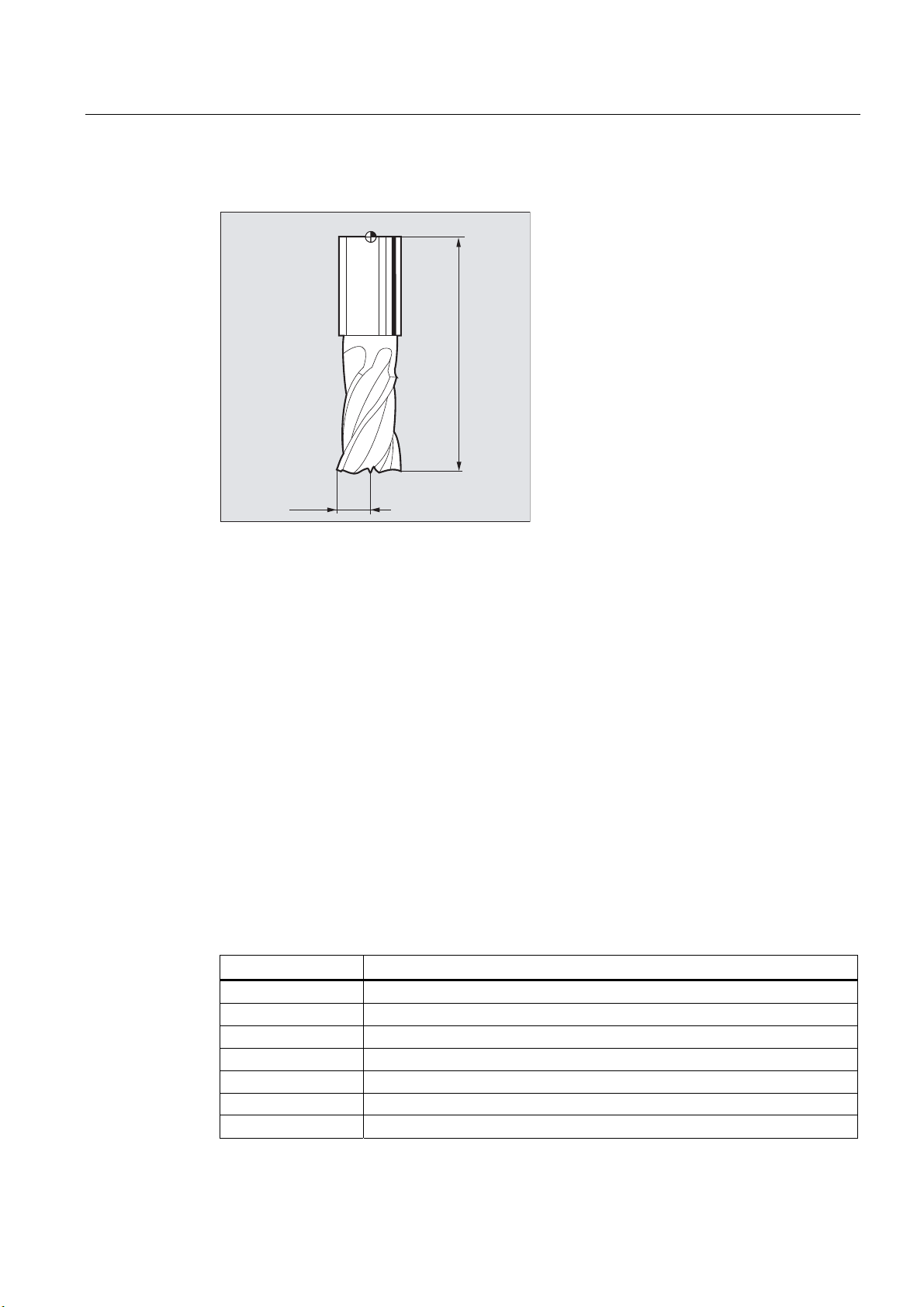
Tool offsets
5.5 Tool types
Tool geometry variables (length, radius)
)
/HQJWK
5DGLXV
The tool geometry variables consist of several components (geometry, wear). The controller
computes the components to a certain dimension (e.g. overall length 1, total radius). The
respective overall dimension becomes effective when the compensation memory is
activated.
How these values are calculated in the axes is determined by the tool type and the current
plane (
G17/G18/G19).
References
Function Manual, Basic Functions; Tool Offsets (W1); Section "Tool edge"
5.5 Tool types
5.5.1 General information about the tool types
Tools are divided into tool types. Each tool type is assigned a 3-digit number. The first digit
assigns the tool type to one of the following groups depending on the technology used:
Tool type Tool group
1xy Milling tools (Page 66)
2xy Drills (Page 68)
3xy Reserved
4xy Grinding tools (Page 69)
5xy Turning tools (Page 70)
6xy Reserved
7xy Special tools (Page 71) such as a slotting saw
Fundamentals
Programming Manual, 03/2013, 6FC5398-1BP40-3BA1
65
Page 66

Tool offsets
5.5 Tool types
5.5.2 Milling tools
The following tool types are available in the "Milling tools" group:
100 Milling tool according to CLDATA (Cutter Location Data)
110 Ballhead cutter (cylindrical die milling tool)
111 Ballhead cutter (tapered die milling tool)
120 End mill (without corner rounding)
121 End mill (with corner rounding)
130 Angle head cutter (without corner rounding)
131 Angle head cutter (with corner rounding)
140 Facing tool
145 Thread cutter
150 Side mill
151 Saw
155 Bevel cutter (without corner rounding)
156 Bevel cutter (with corner rounding)
157 Tapered die milling tool
160 Drill and thread milling cutter
Tool parameters
The following figures provide an overview of which tool parameters (DP...) for milling tools
are entered in the compensation memory:
(QWULHVLQ
WRROSDUDPHWHUV
'3
'3
'3
'3
:HDUYDOXHV
DVUHTXLUHG
6HWUHPDLQLQJ
YDOXHVWR
$IL[HGDVVLJQPHQWLVSRVVLEOHIRU***
HJOHQJWK ;OHQJWK =OHQJWK <VHH)%:7RROFRPSHQV
[\
*HRPHWU\OHQJWK
*HRPHWU\UDGLXV
$GDSWHUOHQJWK
))
/HQJWK
/HQJWK7RWDO
)5HIHUHQFHSRLQWDGDSWHUZLWKWRRO
LQVHUWHG WRROKROGHUUHIHUHQFHSRLQW
(IIHFW
/HQJWKLQ=
*
5DGLXVLQ;<
/HQJWKLQ<
*
5DGLXVLQ=;
/HQJWKLQ;
*
5DGLXVLQ<=
/HQJWK$GDSWHU
)v7RROKROGHU
UHIHUHQFHSRLQW
Fundamentals
66 Programming Manual, 03/2013, 6FC5398-1BP40-3BA1
Page 67

Tool offsets
5.5 Tool types
(QWULHVLQ
WRROSDUDPHWHUV
'3
[\
*HRPHWU\OHQJWK
'3
*HRPHWU\UDGLXV
'3
%DVHOHQJWK
'3
'3
%DVHOHQJWK
'3
%DVHOHQJWK
:HDUYDOXHVDFFWR
UHTXLUHPHQWV
6HWUHPDLQLQJ
YDOXHVWR
7RROEDVH
GLPHQVLRQ
OHQJWK
(IIHFW
*
/HQJWKLQ=
/HQJWKLQ<
/HQJWKLQ;
5DGLXV75&LQ;<
*
/HQJWKLQ<
/HQJWKLQ;
/HQJWKLQ=
5DGLXV75&LQ=;
*
/HQJWKLQ;
/HQJWKLQ=
/HQJWKLQ<
5DGLXV75&LQ<=
)
7RROEDVH
)
GLPHQVLRQ
OHQJWK
)v7RROKROGHUUHIHUHQFHSRLQW
)7RROKROGHUUHIHUHQFHSRLQW
5DGLXV
;
=
<
7RROEDVH
=
<
;
GLPHQVLRQ
OHQJWK
<
;
=
$IL[HGDVVLJQPHQWLVSRVVLEOHIRU***
HJOHQJWK ;OHQJWK <OHQJWK =VHH)%:7RROFRPSHQVDWLRQ
Note
Brief description of the tool parameters can be found on the user interface.
For further information, see:
References:
Function Manual, Basic Functions; Tool Offset (W1)
Fundamentals
Programming Manual, 03/2013, 6FC5398-1BP40-3BA1
67
Page 68

Tool offsets
5.5 Tool types
5.5.3 Drills
The following tool types are available in the "Drills" group:
200 Twist drill
205 Drill
210 Boring bar
220 Center drill
230 Countersink
231 Counterbore
240 Tap regular thread
241 Tap fine thread
242 Tap Whitworth thread
250 Reamer
Tool parameters
The following figure provides an overview of which tool parameters (DP...) for drills are
entered in the compensation memory:
(QWULHVLQ
WRROSDUDPHWHUV
'3
'3
:HDUYDOXHV
DVUHTXLUHG
6HWUHPDLQLQJ
YDOXHVWR
Note
[\
/HQJWK
(IIHFW
*
*
*
/HQJWK
/HQJWKLQ=
/HQJWKLQ<
/HQJWKLQ;
)
)7RROKROGHU
UHIHUHQFHSRLQW
Brief description of the tool parameters can be found on the user interface.
For further information, see:
References:
Function Manual, Basic Functions; Tool Offset (W1)
Fundamentals
68 Programming Manual, 03/2013, 6FC5398-1BP40-3BA1
Page 69

Tool offsets
5.5 Tool types
5.5.4 Grinding tools
The following tool types are available in the "Grinding tools" group:
400 Surface grinding wheel
401 Surface grinding wheel with monitoring
402 Surface grinding wheel without monitoring without base dimension (TOOLMAN)
403 Surface grinding wheel with monitoring without base dimension for grinding wheel
peripheral speed GWPS
410 Facing wheel
411 Facing wheel (TOOLMAN) with monitoring
412 Facing wheel (TOOLMAN) without monitoring
413 Facing wheel with monitoring without base dimension for grinding wheel peripheral
speed GWPS
490 Dresser
Tool parameters
The following figure provides an overview of which tool parameters (DP...) for grinding tools
are entered in the compensation memory:
(QWULHVLQWKHWRRO
SDUDPHWHUV
'3
'3
'3
'3
'3
7RROQRVHSRVLWLRQ
:HDUYDOXHV
FRUUHVSRQGWRWKH
UHTXLUHPHQW
2WKHUYDOXHVVKRXOG
EHVHWWR
(IIHFW
*
*
*
Note
3RVLWLRQ
/HQJWK
/HQJWK
5DGLXV
/HQJWKLQ<
/HQJWKLQ;
5DGLXVLQ;<
/HQJWKLQ;
/HQJWKLQ=
5DGLXVLQ=;
/HQJWKLQ=
/HQJWKLQ<
5DGLXVLQ<=
6SLQGOHQXPEHU
73*
&KDLQLQJUXOH
73*
0LQLPXPZKHHOUDGLXV
73*
0LQZKHHOZLGWK
73*
$FWXDOZKHHOZLGWK
73*
0D[LPXPVSHHG
73*
73*
0D[SHULSKHUDOVSHHG
$QJOHRIWKHLQFOLQHGZKHHO
73*
3DUDPHWHU1RIRUUDGLXVFDOFXODWLRQ
73*
)7RROFDUULHUUHIHUHQFHSRLQW
)
5DGLXV
)
*HRPHWU\
/HQJWK
%DVLV
%DVLVOHQJWK
/HQJWK
*HRPHWU\
/HQJWK
Brief description of the tool parameters can be found on the user interface.
For further information, see:
References:
Function Manual, Basic Functions; Tool Offset (W1)
Fundamentals
Programming Manual, 03/2013, 6FC5398-1BP40-3BA1
69
Page 70
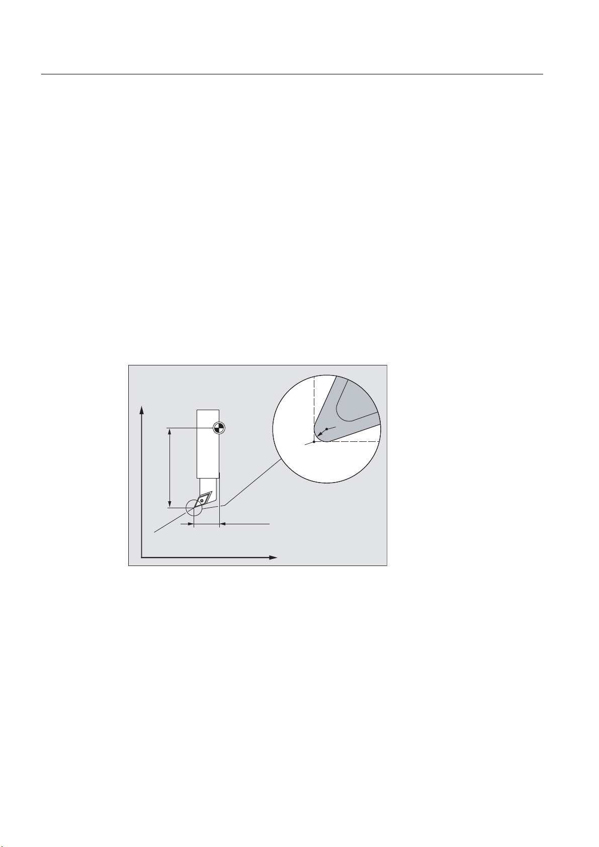
Tool offsets
5.5 Tool types
5.5.5 Turning tools
The following tool types are available in the "Turning tools" group:
500 Roughing tool
510 Finishing tool
520 Plunge cutter
530 Parting tool
540 Threading tool
550 Button tool / forming tool (TOOLMAN)
560 Rotary drill (ECOCUT)
580 Probe with cutting edge position parameters
Tool parameters
The following figures provide an overview of which tool parameters (DP...) for turning tools
are entered in the compensation memory:
7XUQLQJWRRO
HJ*=;SODQH
)7RROKROGHUUHIHUHQFHSRLQW
;
/HQJWK;
7RROWLS3
WRROHGJH 'Q
)
3
5UDGLXVRIWRROQRVH
WRROUDGLXV
6SRVLWLRQRIWRROQRVHFHQWHU
/HQJWK=
=
6
5
Fundamentals
70 Programming Manual, 03/2013, 6FC5398-1BP40-3BA1
Page 71

Tool offsets
5.5 Tool types
7KHWRROSDUDPHWHU'3VSHFLILHVWKHOHQJWKRIWKHWRROQRVH
3RVLWLRQYDOXHWRSRVVLEOH
7RROQRVHSRVLWLRQ'3
;
3
=
;
(QWULHVLQ
WRROSDUDPHWHUV
'3
[\
'3
/HQJWK
'3
/HQJWK
'3
'3
5DGLXV
Note
1RWH
3DUDPHWHUVOHQJWKOHQJWKUHIHUWRWKH
SRLQWZLWKWRROQRVHSRVLWLRQEXWWR6
6 3ZLWK
:HDUYDOXHV
DVUHTXLUHG
6HWUHPDLQLQJ
YDOXHVWR
3 6
=
(IIHFW
/HQJWKLQ<
*
/HQJWKLQ;
/HQJWKLQ;
*
/HQJWKLQ=
/HQJWKLQ=
*
/HQJWKLQ<
Brief description of the tool parameters can be found on the user interface.
For further information, see:
References:
Function Manual, Basic Functions; Tool Offset (W1)
5.5.6 Special tools
The following tool types are available in the "Special tools" group:
700 Slotting saw
710 3D probe
711 Edge probe
730 Stop
Fundamentals
Programming Manual, 03/2013, 6FC5398-1BP40-3BA1
71
Page 72

Tool offsets
5.5 Tool types
Tool parameters
The following figure provides an overview of which tool parameters (DP...) for "Slotting saw"
tool type are entered in the compensation memory:
(QWULHVLQ
WRROSDUDPHWHUV
'3%DVHOHQJWK
'3%DVHOHQJWK
'3*HRPHWU\GLDPHWHU
'3*HRPHWU\]HURZLGWK
'3*HRPHWU\RYHUVKRRW
:HDUYDOXHV
DVUHTXLUHG
6HWUHPDLQLQJ
YDOXHVWR
7RROEDVHGLPHQVLRQ
(IIHFW
*+DOIGLDPHWHU/LQ;3ODQHVHOHFWLRQ
([FHVVGLPLQ/<VWQGD[LV;<
6DZEODGHLQ5;<
*+DOIGLDPHWHU/LQ<3ODQHVHOHFWLRQ
([FHVVGLPLQ/;VWQGD[LV;=
6DZEODGHLQ5=;
*+DOIGLDPHWHU/LQ=3ODQHVHOHFWLRQ
([FHVVGLPLQ/=VWQGD[LV<=
6DZEODGHLQ5<=
6ORWZLGWKE
/HQJWK
([FHVVGLP
N
'LDPHWHUG
/HQJWK
7RROEDVHGLPHQVLRQ
Note
Brief description of the tool parameters can be found on the user interface.
For further information, see:
References:
Function Manual, Basic Functions; Tool Offset (W1)
5.5.7 Chaining rule
The geometry tool length compensations, wear and base dimension can be chained for both
the left and the right tool nose radius compensation, i.e. if the tool length compensations are
changed for the left cutting edge, then the values are also automatically entered for the right
cutting edge and vice versa.
References
Function Manual, Extended Functions; Grinding (W4)
Fundamentals
72 Programming Manual, 03/2013, 6FC5398-1BP40-3BA1
Page 73

Tool offsets
5.6 Tool offset call (D)
5.6 Tool offset call (D)
Function
Cutting edges 1 to 8 (with active TOOLMAN 12) of a tool can be assigned different tool offset
data records (e.g. different offset values for the left and right cutting edge of a grooving tool).
Activation of the offset data (including the data for the tool length compensation) of a special
cutting edge is performed by calling the D number. When
tool have no effect.
D0 is programmed, offsets for the
Syntax
Meaning
A tool radius compensation must also be activated via
Note
G41/G42.
Tool length offsets take immediate effect when the D number is programmed. If no D number
is programmed, the default setting defined via the machine data is active for a tool change
(→ see machine manufacturer's specifications).
Activation of a tool offset data record:
D<number>
Activate the tool radius compensation:
G41 ...
G42 ...
Deactivation of the tool offsets:
D0
G40
D: Command for the activation of an offset data record for the active tool
The tool length compensation is applied with the first programmed traverse
of the associated length compensation axis.
Notice:
A tool length compensation can also take effect without D programming,
when the automatic activation of a tool edge has been configured for the tool
change (→ see machine manufacturer's specifications).
<number>:
The tool offset data record to be activated is specified via the <number>
parameter.
The type of D programming depends on the configuration of the machine
(see paragraph "Type of D programming").
Range of values: 0 - 32000
D0: Command for the deactivation of the offset data record for the active tool
Fundamentals
Programming Manual, 03/2013, 6FC5398-1BP40-3BA1
73
Page 74

Tool offsets
5.6 Tool offset call (D)
G41
: Command for the activation of the tool radius compensation with machining
direction left of the contour
G42: Command for the activation of the tool radius compensation with machining
direction right of the contour
G40: Command for the deactivation of the tool radius compensation
Note
The tool radius compensation is described in detail in the section "Tool radius compensation"
section.
Type of D programming
The type of D programming is defined via machine data.
This can be done as follows:
● D number = cutting edge number
Examples
D numbers ranging from 1 to max. 12 are available for every tool T<number> or
T="Name" (with TOOLMAN). These D numbers are assigned directly to the tool cutting
edges. A compensation data record ($TC_DPx[t,d]) belongs to each D number (= cutting
edge number).
● Free selection of D numbers
The D numbers can be freely assigned to the cutting edge numbers of a tool. The upper
limit for the D numbers that can be used is limited by a machine data.
● Absolute D number without reference to the T number
Independence between D number and T number can be selected in systems without tool
management. The reference of T number, cutting edge and offset by the D number is
defined by the user. The range of D numbers is between 1 and 32000.
References:
Function Manual, Basic Functions; Tool Offset (W1),
Function Manual, Tool Management, Section: "Variants of D-number assignments"
Example 1: Tool change with T command (turning)
Program code Comment
N10 T1 D1 ; Load tool T1 and activate tool offset data record D1 of T1.
N11 G0 X... Z... ; The tool length compensations are applied.
N50 T4 D2 ; Load tool T4 and activate tool offset data record D2 of T4.
...
N70 G0 Z... D1 ; Activate other cutting edge D1 for tool T4.
Fundamentals
74 Programming Manual, 03/2013, 6FC5398-1BP40-3BA1
Page 75

Tool offsets
5.7 Change in the tool offset data
Example 2: Different offset values for the left and right cutting edge of a grooving tool
N10 T2
N20 G0
N30 G1
X35 Z-20
D1 X10
N40...
-20
D6 Z-5
-5
5.7 Change in the tool offset data
Effectiveness
X
10
Z
A change in the tool offset data takes effect the next time the T or D number is programmed.
Set tool offset data to be active immediately
The following machine data can be used to specify that entered tool offset data takes effect
immediately:
MD9440 $MM_ACTIVATE_SEL_USER
WARNING
Risk of collision
If MD9440 is set, tool offsets resulting from changes in tool offset data during the part
program stop, are applied when the part program is continued.
Fundamentals
Programming Manual, 03/2013, 6FC5398-1BP40-3BA1
75
Page 76

Tool offsets
5.8 Programmable tool offset (TOFFL, TOFF, TOFFR)
5.8 Programmable tool offset (TOFFL, TOFF, TOFFR)
Function
The user can use the commands TOFFL/TOFF and TOFFR to modify the effective tool length or
the effective tool radius in the NC program, without changing the tool offset data stored in the
compensation memory.
These programmed offsets are deleted again at the end of the program.
Tool length offset
Depending on the type of programming, programmed tool length offsets are assigned either
to the tool length components L1, L2 and L3 (
to the geometry axes (
change (
G17/G18/G19 ↔ G17/G18/G19):
TOFF). The programmed offsets are treated accordingly for a plane
● If the offset values are assigned to the tool length components, the directions in which the
programmed offsets apply, are replaced accordingly.
● If the offset values are assigned to the geometry axes, a plane change does not effect the
assignment in relation to the coordinate axes.
TOFFL) stored in the compensation memory or
Syntax
Tool radius offset
The command
TOFFR is available for the programming of a tool radius offset.
Tool length offset:
TOFFL=<value>
TOFFL[1]=<value>
TOFFL[2]=<value>
TOFFL[3]=<value>
TOFF[<geometry axis>]=<value>
Tool radius offset:
TOFFR=<value>
Fundamentals
76 Programming Manual, 03/2013, 6FC5398-1BP40-3BA1
Page 77

Tool offsets
5.8 Programmable tool offset (TOFFL, TOFF, TOFFR)
Meaning
TOFFL: Command for the compensation of the effective tool length
TOFFL can be programmed with or without index:
Without index:
The programmed offset value is applied in the same direction
as the tool length component L1 stored in the compensation
memory.
With index:
The programmed offset value is applied in the same direction
as the tool length component L1, L2 or L3 stored in the offset
memory.
The commands
Note:
How these tool length offset values are calculated in the axes is
determined by the tool type and the current working plane
G17/G18/G19).
(
TOFF: Command for the compensation of the tool length in the
component parallel to the specified geometry axis
TOFF is applied in the direction of the tool length component, which
is effective with non-rotated tool (orientable toolholder or
orientation transformation) parallel to the
specified in the index.
Note:
A frame does not influence the assignment of the programmed
values to the tool length components, i.e. the workpiece
coordinate system (WCS) is not used for the assignment of the
tool length components to the geometry axes, but the tool in the
basic tool position.
<geometry axis>: Identifier of the geometry axis
TOFFR: Command for the compensation of the effective tool radius
TOFFR changes the effective tool radius with active tool radius
compensation by the programmed offset value.
<value>:
Offset value for the tool length or radius
Type: REAL
Note
TOFFL=
TOFFL[1]=, TOFFL[2]= or TOFFL[3]=
TOFFL and TOFFL[1] have an identical effect.
<geometry axis>
The
TOFFR command has almost the same effect as the OFFN command (see "Tool radius
compensation (Page 257)"). There is only a difference with active periph
transformation (TRACYL) and active slot side compensation. In this case, the tool radius is
affected by
OFFN and TOFFR can be effective simultaneously. They then generally have an additive effect
OFFN with a negative sign, but by TOFFR with a positive sign.
(except for slot side compensation).
Fundamentals
Programming Manual, 03/2013, 6FC5398-1BP40-3BA1
eral curve
77
Page 78

Tool offsets
5.8 Programmable tool offset (TOFFL, TOFF, TOFFR)
Further syntax rules
● The tool length can be changed simultaneously in all three components. However,
commands of the
TOFFL/TOFFL[1..3] group and commands of the TOFF[<geometry axis>]
may not be used simultaneously in one block.
TOFFL and TOFFL[1] may also not be written simultaneously in one block.
● If all three tool length components are not programmed in a block, the components not
programmed remain unchanged. In this way, it is possible to build up offsets for several
components block-by-block. However, this only applies as long as the tool components
have been modified either only with
type from
TOFFL to TOFF or vice versa deletes any previously programmed tool length
TOFFL or only with TOFF. Changing the programming
offsets (see example 3).
Supplementary conditions
● Evaluation of setting data
The following setting data is evaluated when assigning the programmed offset values to
the tool length components:
Examples
SD42940 $SC_TOOL_LENGTH_CONST (change of tool length components on change
of planes).
SD42950 $SC_TOOL_LENGTH_TYPE (assignment of the tool length compensation
independent of tool type)
If this setting data has valid values not equal to 0, then these take preference over the
contents of G code group 6 (plane selection
G17 - G19) or the tool type ($TC_DP1[<T no.>,
<D no.>]) contained in the tool data, i.e. this setting data influences the evaluation of the
offsets in the same way as the tool length components L1 to L3.
● Tool change
All offset values are retained during a tool change (cutting edge change), e.g. they are
also effective for the new tool (new cutting edge).
Example 1: Positive tool length offset
The active tool is a drill with length L1 = 100 mm.
The active plane is
G17, i.e. the drill points in the Z direction.
The effective drill length is to be increased by 1 mm. The following variants are available for
the programming of this tool length offset:
TOFFL=1
or
TOFFL[1]=1
or
TOFF[Z]=1
Fundamentals
78 Programming Manual, 03/2013, 6FC5398-1BP40-3BA1
Page 79

Tool offsets
5.8 Programmable tool offset (TOFFL, TOFF, TOFFR)
Example 2: Negative tool length offset
The active tool is a drill with length L1 = 100 mm.
The active plane is
G18, i.e. the drill points in the Y direction.
The effective drill length is to be decreased by 1 mm. The following variants are available for
the programming of this tool length offset:
TOFFL=-1
or
TOFFL[1]=-1
or
TOFF[Y]=1
Example 3: Changing the programming type from TOFFL to TOFF
The active tool is a milling tool. The active plane is
Program code Comment
N10 TOFFL[1]=3 TOFFL[3]=5 ; Effective offsets: L1=3, L2=0, L3=5
N20 TOFFL[2]=4 ; Effective offsets: L1=3, L2=4, L3=5
N30 TOFF[Z]=1.3 ; Effective offsets: L1=0, L2=0, L3=1.3
G17.
Example 4: Plane change
Program code Comment
N10 $TC_DP1[1,1]=120
N20 $TC_DP3[1,1]= 100 ; Tool change L1=100 mm.
N30 T1 D1 G17
N40 TOFF[Z]=1.0 ; Offset in Z direction (corresponds to L1 for G17).
N50 G0 X0 Y0 Z0 ; Machine axis position X0 Y0 Z101.
N60 G18 G0 X0 Y0 Z0. ; Machine axis position X0 Y100 Z1.
N70 G17
N80 TOFFL=1.0 ; Offset in L1 direction (corresponds to Z for G17).
N90 G0 X0 Y0 Z0 ; Machine axis position X0 Y0 Z101.
N100 G18 G0 X0 Y0 Z0 ; Machine axis position X0 Y101 Z0.
In this example, the offset of 1 mm in the Z axis is retained when changing to G18 in block
N60; the effective tool length in the Y axis is the unchanged tool length of 100 mm.
However, in block
N100, the offset is effective in the Y axis when changing to G18 as it was
assigned to tool length L1 in the programming and this length component is effective in the Y
axis with
Fundamentals
Programming Manual, 03/2013, 6FC5398-1BP40-3BA1
G18.
79
Page 80

Tool offsets
5.8 Programmable tool offset (TOFFL, TOFF, TOFFR)
Further information
Applications
The "Programmable tool offset" function is especially interesting for ball mills and milling
tools with corner radii as these are often calculated in the CAM system to the ball center
instead of the ball tip. However, generally the tool tip is measured when measuring the tool
and stored as tool length in the compensation memory.
System variables for reading the current offset values
The currently effective offsets can be read with the following system variables:
System variables Meaning
$P_TOFFL [<n>] with 0 ≤ n ≤ 3 Reads the current offset value of TOFFL (for
n = 0) or TOFFL[1...3] (for n = 1, 2, 3) in the
preprocessing context.
$P_TOFF [<geometry axis>] Reads the current offset value of
TOFF[<geometry axis>] in the preprocessing
context.
$P_TOFFR Reads the current offset value of TOFFR in the
preprocessing context.
$AC_TOFFL[<n>] with 0 ≤ n ≤ 3 Reads the current offset value of TOFFL (for
n = 0) or TOFFL[1...3] (for n = 1, 2, 3) in the
main run context (synchronized actions).
$AC_TOFF[<geometry axis>] Reads the current offset value of
TOFF[<geometry axis>] in the main run
context (synchronized actions).
$AC_TOFFR Reads the current offset value of TOFFR in the
main run context (synchronized actions).
Note
The system variables $AC_TOFFL, $AC_TOFF and AC_TOFFR trigger an automatic
preprocessing stop when reading from the preprocessing context (NC program).
Fundamentals
80 Programming Manual, 03/2013, 6FC5398-1BP40-3BA1
Page 81

Spindle motion
6.1 Spindle speed (S), spindle direction of rotation (M3, M4, M5)
Function
The spindle speed and direction of rotation values set the spindle in rotary motion and
provide the conditions for chip removal.
;; ;
6
Syntax
=
Figure 6-1 Spindle motion during turning
Other spindles may be available in addition to the main spindle (e.g. the counterspindle or an
actuated tool on turning machines). As a rule, the main spindle is declared the master
spindle in the machine data. This assignment can be changed using an NC command.
S... / S<n>=...
M3 / M<n>=3
M4 / M<n>=4
M5 / M<n>=5
SETMS(<n>)
...
SETMS
Fundamentals
Programming Manual, 03/2013, 6FC5398-1BP40-3BA1
81
Page 82

Spindle motion
6
6.1 Spindle speed (S), spindle direction of rotation (M3, M4, M5)
Meaning
S…: Spindle speed in rpm for the master spindle
S<n>=... : Spindle speed in rpm for spindle <n>
Note:
The speed specified with
M3: Direction of spindle rotation clockwise for master spindle
M<n>=3: Spindle direction of rotation clockwise for spindle <n>
M4: Direction of spindle rotation counter-clockwise for master spindle
M<n>=4: Spindle direction of rotation counter-clockwise for spindle <n>
M5: Spindle stop for master spindle
M<n>=5: Spindle stop for spindle <n>
SETMS(<n>): Set spindle <n> as master spindle
SETMS: If SETMS is programmed without a spindle name, the configured master
spindle is used instead.
Note
S0=… applies to the master spindle.
Example
Up to three S-values can be programmed per NC block, e.g.:
S... S2=... S3=...
Note
SETMS must be in a separate block.
S1 is the master spindle, S2 is the second spindle. The part is to be machined from two
sides. To do this, it is necessary to divide the operations into steps. After the cut-off point,
the synchronizing device (S2) takes over machining of the workpiece after the cut off. To do
this, this spindle S2 is defined as the master spindle to which G95 then applies.
6
6
Fundamentals
82 Programming Manual, 03/2013, 6FC5398-1BP40-3BA1
Page 83

Spindle motion
6.1 Spindle speed (S), spindle direction of rotation (M3, M4, M5)
Program code Comment
N10 S300 M3 ; Speed and direction of rotation for drive spindle =
preset master spindle
... ; Machining of the right-hand workpiece side
N100 SETMS(2) ; S2 is now the master spindle
N110 S400 G95 F… ; Speed for new master spindle
... ; Machining of the left-hand workpiece side
N160 SETMS ; Switching back to master spindle S1
Further information
Interpretation of the S-value for the master spindle
If function G331 or G332 is active in G function group 1 (modally valid motion commands),
the programmed S-value will always be interpreted as the speed in rpm. Otherwise, the
interpretation of the S-value will depend upon G function group 15 (feedrate type): If G96,
G961 or G962 is active, the S-value is interpreted as a constant cutting rate in m/min;
otherwise, it is interpreted as a speed in rpm.
Changing from G96/G961/G962 to G331/G332 sets the value of the constant cutting rate to
zero; changing from G331/G332 to a function within the G function group other than
G331/G332 sets the speed value to zero. The corresponding S-values have to be
reprogrammed if required.
Preset M commands M3, M4, M5
In a block with axis commands, functions M3, M4, M5 are activated before the axis
movements commence (basic setting on the control).
Example:
Program code Comment
N10 G1 F500 X70 Y20 S270 M3 ; The spindle ramps up to 270 rpm, then the
movements are executed in X and Y.
N100 G0 Z150 M5 ; Spindle stop before the retraction movement
in Z.
Note
Machine data can be used to set when axis movements should be executed; either once the
spindle has powered up to the setpoint speed, or immediately after the programmed
switching operations have been traversed.
Fundamentals
Programming Manual, 03/2013, 6FC5398-1BP40-3BA1
83
Page 84

Spindle motion
6.1 Spindle speed (S), spindle direction of rotation (M3, M4, M5)
Working with multiple spindles
5 spindles (master spindle plus 4 additional spindles) can be available in one channel at the
same time.
One of the spindles is defined in machine data as the master spindle. Special functions such
as thread cutting, tapping, revolutional feedrate, and dwell time apply to this spindle. For the
remaining spindles (e.g. a second spindle and an actuated tool) the numbers corresponding
to the speed and the direction of rotation/spindle stop must be specified.
Example:
Program code Comment
N10 S300 M3 S2=780 M2=4 ; Master spindle: 300 rpm, CW rotation
2nd spindle: 780 rpm, CCW rotation
Programmable switchover of master spindle
The
SETMS(<n>) command can be used in the NC program to define any spindle as the
master spindle.
SETMS must be in a separate block.
Example:
Program code Comment
N10 SETMS (2) ; Spindle 2 is now the master spindle.
Note
The speed specified with
S..., along with the functions programmed with M3, M4, M5, now
apply to the newly declared master spindle.
If SETMS is programmed without a spindle name, the master spindle programmed in the
machine data is used instead.
Fundamentals
84 Programming Manual, 03/2013, 6FC5398-1BP40-3BA1
Page 85

Spindle motion
6.2 Cutting rate (SVC)
6.2 Cutting rate (SVC)
Function
As an alternative to the spindle speed, the tool cutting rate, which is more commonly used in
practice, can be programmed for milling operations.
7RROUDGLXV
6SHHG
&XWWLQJUDWH
The controller uses the radius of the active tool to calculate the effective spindle speed from
the programmed tool cutting rate:
S = (SVC * 1000) / (R
with:
S: Spindle speed in rpm
* 2π)
T
SVC: Cutting rate in m/min or ft/min
: Radius of the active tool in mm
R
T
The tool type ($TC_DP1) of the active tool is not taken into account.
The programmed cutting rate is independent of the path feedrate
The direction of rotation and the spindle start are programmed using
and the spindle stop using
M5.
F and G function group 15.
M3 and M4 respectively
A change to the tool radius data in the offset memory will be applied the next time a tool
offset is selected or the next time the active offset data is updated.
Changing the tool or selecting/deselecting a tool offset data record generates a recalculation
of the effective spindle speed.
Requirements
The programming of the cutting speed requires:
● The geometric ratios of a rotating tool (milling cutter or drilling tool)
● An active tool offset data record
Fundamentals
Programming Manual, 03/2013, 6FC5398-1BP40-3BA1
85
Page 86

Spindle motion
6.2 Cutting rate (SVC)
Syntax
SVC[<n>]=<value>
Note
Meaning
In the block with
SVC, the tool radius must be known; in other words, a corresponding tool
including a tool offset data record must be active or selected in the block. There is no fixed
sequence for
SVC:
SVC and T/D selection during programming in the same block.
Cutting rate
[<n>]: Number of spindle
This address extension specifies which spindle the programmed
cutting rate is to be applied for. In the absence of an address
extension, the rate is always applied to the master spindle.
Note:
A separate cutting rate can be preset for each spindle.
Note:
Programming
SVC without an address extension requires that the
master spindle has the active tool. If the master spindle changes,
the user will need to select a tool accordingly.
Unit: m/min or ft/min (dependent upon G700/G710)
Note
Changing between SVC and S
Changing between
SVC and S programming is possible at will, even while the spindle is
turning. In each case, the value that is not active is deleted.
Note
Maximum tool speed
System variable $TC_TP_MAX_VELO[<tool number>] can be used to preset a maximum
tool speed (spindle speed).
If no speed limit has been defined, there will be no monitoring.
Fundamentals
86 Programming Manual, 03/2013, 6FC5398-1BP40-3BA1
Page 87

Spindle motion
6.2 Cutting rate (SVC)
Examples
Note
SVC programming is not possible if the following are active:
G96/G961/G962
GWPS
SPOS/SPOSA/M19
M70
Conversely, programming one of these commands will lead to the deselection of
SVC.
Note
The tool paths of "standard tools" generated, e.g. using CAD systems which already take the
tool radius into account and only contain the deviation from the standard tool in the tool nose
radius are not supported in conjunction with
SVC programming.
The following shall apply to all examples: Toolholder = spindle (for standard milling)
Example 1: Milling cutter 6 mm radius
Program code Comment
N10 G0 X10 T1 D1 ; Selection of milling cutter with, e.g.
$TC_DP6[1,1] = 6 (tool radius = 6 mm)
N20 SVC=100 M3 ; Cutting rate = 100 m/min
⇒ Resulting spindle speed:
S = (100 m/min * 1000) / (6.0 mm * 2 * 3.14) =
2653.93 rpm
N30 G1 X50 G95 FZ=0.03 ; SVC and tooth feedrate
...
Example 2: Tool selection and SVC in the same block
Program code Comment
N10 G0 X20
N20 T1 D1 SVC=100 ; Tool and offset data record selection together with
N30 X30 M3 ; Spindle start with CW direction of rotation,
N40 G1 X20 F0.3 G95 ; SVC and revolutional feedrate
Fundamentals
Programming Manual, 03/2013, 6FC5398-1BP40-3BA1
SVC in block (no specific sequence)
cutting rate 100 m/min
87
Page 88

Spindle motion
6.2 Cutting rate (SVC)
Example 3: Defining cutting rates for two spindles
Program code Comment
N10 SVC[3]=100 M6 T1 D1
N20 SVC[5]=200 ; The tool radius of the active tool offset is the
same for both spindles. The effective speed is
different for spindle 3 and spindle 5.
Example 4:
Assumptions:
Master or tool change is determined by the toolholder.
MD20124 $MC_TOOL_MANAGEMENT_TOOLHOLDER > 1
In the event of a tool change the old tool offset is retained. A tool offset for the new tool is
only activated when
D is programmed:
MD20270 $MC_CUTTING_EDGE_DEFAULT = - 2
Program code Comment
N10 $TC_MPP1[9998,1]=2 ; Magazine location is toolholder
N11 $TC_MPP5[9998,1]=1 ; Magazine location is toolholder 1
N12 $TC_MPP_SP[9998,1]=3 ; Toolholder 1 is assigned to spindle 3
N20 $TC_MPP1[9998,2]=2 ; Magazine location is toolholder
N21 $TC_MPP5[9998,2]=4 ; Magazine location is toolholder 4
N22 $TC_MPP_SP[9998,2]=6 ; Toolholder 4 is assigned to spindle 6
N30 $TC_TP2[2]="WZ2"
N31 $TC_DP6[2,1]=5.0 ; Radius = 5.0 mm of T2, offset D1
N40 $TC_TP2[8]="WZ8"
N41 $TC_DP6[8,1]=9.0 ; Radius = 9.0 mm of T8, offset D1
N42 $TC_DP6[8,4]=7.0 ; Radius = 7.0 mm of T8, offset D4
...
N100 SETMTH(1) ; Set master toolholder number
N110 T="WZ2" M6 D1 ; Tool T2 is loaded and offset D1 is activated.
N120 G1 G94 F1000 M3=3 SVC=100 ; S3 = (100 m/min * 1,000) / (5.0 mm * 2 * 3.14) =
3184.71 rpm
N130 SETMTH(4) ; Set master toolholder number
N140 T="WZ8" ; Corresponds to T8="WZ8"
N150 M6 ; Corresponds to M4=6
Tool "WZ8" is in the master toolholder, but because
MD20270=–2, the old tool offset remains active.
N160 SVC=50 ; S3 = (50 m/min * 1,000) / (5.0 mm * 2 * 3.14) = 1592.36 rpm
Fundamentals
88 Programming Manual, 03/2013, 6FC5398-1BP40-3BA1
Page 89

Spindle motion
6.2 Cutting rate (SVC)
Program code Comment
The offset applied to toolholder 1 is still active and
toolholder 1 is assigned to spindle 3.
N170 D4
N180 SVC=300 ; S6 = (300 m/min * 1,000) / (7.0 mm * 2 * 3.14) =
Offset D4 of the new tool "WZ8" becomes active (in
toolholder 4).
6824.39 rpm
Spindle 6 is assigned to toolholder 4.
Example 5:
Assumptions:
Spindles are toolholders at the same time:
MD20124 $MC_TOOL_MANAGEMENT_TOOLHOLDER = 0
In the event of a tool change tool offset data record D4 is selected automatically.
MD20270 $MC_CUTTING_EDGE_DEFAULT = 4
Program code Comment
N10 $TC_MPP1[9998,1]=2 ; Magazine location is toolholder
N11 $TC_MPP5[9998,1]=1 ; Magazine location is toolholder 1 = spindle 1
N20 $TC_MPP1[9998,2]=2 ; Magazine location is toolholder
N21 $TC_MPP5[9998,2]=3 ; Magazine location is toolholder 3 = spindle 3
N30 $TC_TP2[2]="WZ2"
N31 $TC_DP6[2,1]=5.0 ; Radius = 5.0 mm of T2, offset D1
N40 $TC_TP2[8]="WZ8"
N41 $TC_DP6[8,1]=9.0 ; Radius = 9.0 mm of T8, offset D1
N42 $TC_DP6[8,4]=7.0 ; Radius = 7.0 mm of T8, offset D4
...
N100 SETMS(1) ; Spindle 1 = master spindle
N110 T="WZ2" M6 D1 ; Tool T2 is loaded and offset D1 is activated.
N120 G1 G94 F1000 M3 SVC=100 ; S1 = (100 m/min * 1,000) / (5.0 mm * 2 * 3.14) =
3184.71 rpm
N200 SETMS(3) ; Spindle 3 = master spindle
N210 M4 SVC=150 ; S3 = (150 m/min * 1,000) / (5.0 mm * 2 * 3.14) =
4777.07 rpm
Refers to tool offset D1 of T="WZ2", S1 continues to turn
at previous speed.
N220 T="WZ8" ; Corresponds to T8="WZ8"
N230 M4 SVC=200 ; S3 = (200 m/min * 1,000) / (5.0 mm * 2 * 3.14) =
6369.43 rpm
Refers to tool offset D1 of T="WZ2".
N240 M6 ; Corresponds to M3=6
Fundamentals
Programming Manual, 03/2013, 6FC5398-1BP40-3BA1
89
Page 90

Spindle motion
6.2 Cutting rate (SVC)
Program code Comment
Tool "WZ8" is in the master spindle, tool offset D4 of the
new tool becomes active.
N250 SVC=50 ; S3 = (50 m/min * 1,000) / (7.0 mm * 2 * 3.14) = 1137.40 rpm
Offset D4 on master spindle is active.
N260 D1 ; Offset D1 of new tool "WZ8" active.
N270 SVC[1]=300 ; S1 = (300 m/min * 1,000) / (9.0 mm * 2 * 3.14) =
5307.86 rpm
S3 = (50 m/min * 1,000) / (9.0 mm * 2 * 3.14) = 884.64 rpm
...
Further information
Tool radius
The following tool offset data (associated with the active tool) affect the tool radius when:
● $TC_DP6 (radius - geometry)
● $TC_DP15 (radius - wear)
● $TC_SCPx6 (offset for $TC_DP6)
● $TC_ECPx6 (offset for $TC_DP6)
The following are not taken into account:
● Online radius compensation
● Allowance on the programmed contour (
OFFN)
Tool radius compensation (G41/G42)
Although tool radius compensation (
G41/G42) and SVC both refer to the tool radius, with regard
to function, they are not linked and are independent of one another.
Tapping without compensating chuck (G331, G332)
SVC programming is also possible in conjunction with G331 or G332.
Synchronized actions
SVC cannot be programmed from synchronized actions.
Fundamentals
90 Programming Manual, 03/2013, 6FC5398-1BP40-3BA1
Page 91

Spindle motion
6.2 Cutting rate (SVC)
Reading the cutting rate and the spindle speed programming variant
The cutting rate of a spindle and the speed programming variant (spindle speed
SVC) can be read using system variables:
rate
● With preprocessing stop in the part program via system variables:
$AC_SVC[<n>] Cutting rate applied when the current main run record for
spindle number <n> was preprocessed.
$AC_S_TYPE[<n>]
Spindle speed programming variant applied when the
current main run record for spindle number <n> was
preprocessed.
Value: Significance:
1 Spindle speed S in rpm
2 Cutting rate SVC in m/min or ft/min
● Without preprocessing stop in the part program via system variables:
$P_SVC[<n>] Programmed cutting rate for spindle <n>
$P_S_TYPE[<n>]
Programmed spindle speed programming variant for
spindle <n>
Value: Significance:
1 Spindle speed S in rpm
2 Cutting rate SVC in m/min or ft/min
S or cutting
Fundamentals
Programming Manual, 03/2013, 6FC5398-1BP40-3BA1
91
Page 92

Spindle motion
6.3 Constant cutting rate (G96/G961/G962, G97/G971/G972, G973, LIMS, SCC)
6.3 Constant cutting rate (G96/G961/G962, G97/G971/G972, G973,
LIMS, SCC)
Function
When the "Constant cutting rate" function is active, the spindle speed is modified as a
function of the respective workpiece diameter so that the cutting rate S in m/min or ft/min
remains constant at the tool edge.
6SLQGOHVSHHG
UHGXFHG
&XWWLQJUDWH
FRQVWDQW
Syntax
6SLQGOHVSHHG
LQFUHDVHG
This results in the following advantages:
● Uniformity and consequently improved surface quality of turned parts
● Machining with less wear on tools
Activating/deactivating constant cutting rate for the master spindle:
G96/G961/G962 S...
...
G97/G971/G972/G973
Speed limitation for the master spindle:
LIMS=<value>
LIMS[<spindle>]=<value>
Other reference axis for G96/G961/G962:
SCC[<axis>]
Note
SCC[<axis>] can be programmed together with G96/G961/G962 or in isolation.
Fundamentals
92 Programming Manual, 03/2013, 6FC5398-1BP40-3BA1
Page 93

Spindle motion
6.3 Constant cutting rate (G96/G961/G962, G97/G971/G972, G973, LIMS, SCC)
Meaning
G96: Constant cutting rate with feedrate type G95: ON
G95 is activated automatically with G96. If G95 has not been activated
previously, a new feedrate value
called.
G961: Constant cutting rate with feedrate type G94: ON
G962:
Constant cutting rate with feedrate type G94 or G95: ON
Note:
See "Feedrate (G93, G94, G95, F, FGROUP, FL, FGREF) (Page 101)" for
information about G94 and G95.
S... :
In conjunction with
G96, G961 or G962, S... is not interpreted as a spindle speed
but as a cutting rate. The cutting rate is always applied to the master spindle.
Unit: m/min (for G71/G710) or ft/min (for G70/G700)
Range of values: 0.1 m/min to 9999 9999.9 m/min
G97: Deactivate constant cutting rate with feedrate type G95
G97 (or G971), S... is again interpreted as a spindle speed in rpm. In the
After
absence of a new spindle speed being specified, the last speed set with
G961) is retained.
(or
G971: Deactivate constant cutting rate with feedrate type G94
G972: Deactivate constant cutting rate with feedrate type G94 or G95
G973: Deactivate constant cutting rate without activating spindle speed limitation
LIMS:
Speed limitation for the master spindle (only applied if G96/G961/G97 active)
On machines with selectable master spindles, limitations of differing values
can be programmed for up to four spindles within one block.
<spindle>: Number of spindle
<value>: Spindle speed upper limit in rpm
SCC: If any of the G96/G961/G962 functions are active, SCC[<axis>] can be used to
assign any geometry axis as a reference axis.
Note
F... will have to be specified when G96 is
G96
When
G96/G961/G962 is selected for the first time, a constant cutting rate S... must be
entered; when
Note
G96/G961/G962 is selected again, the entry is optional.
The speed limitation programmed with
G26 or defined in the setting data.
with
Fundamentals
Programming Manual, 03/2013, 6FC5398-1BP40-3BA1
Note
The reference axis for
time when
G96/G961/G962 functions are active.
the
SCC[<axis>] is programmed. SCC[<axis>] can also be programmed when any of
G96/G961/G962 must be a geometry axis assigned to the channel at the
LIMS must not exceed the speed limit programmed
93
Page 94

Spindle motion
6.3 Constant cutting rate (G96/G961/G962, G97/G971/G972, G973, LIMS, SCC)
Examples
Example 1: Activating the constant cutting rate with speed limitation
Program code Comment
N10 SETMS (3)
N20 G96 S100 LIMS=2500 ; Constant cutting rate = 100 m/min,
max. speed 2,500 rpm
...
N60 G96 G90 X0 Z10 F8 S100 LIMS=444 ; Max. speed = 444 rpm
Example 2: Defining speed limitation for 4 spindles
Speed limitations are defined for spindle 1 (master spindle) and spindles 2, 3, and 4:
Program code
N10 LIMS=300 LIMS[2]=450 LIMS[3]=800 LIMS[4]=1500
...
Example 3: Y-axis assignment for face cutting with X axis
Program code Comment
N10 G18 LIMS=3000 T1 D1 ; Speed limitation to 3.000 rpm
N20 G0 X100 Z200
N30 Z100
N40 G96 S20 M3 ; Constant cutting rate = 20 m/min, is dependent upon
X axis.
N50 G0 X80
N60 G1 F1.2 X34 ; Face cutting in X at 1.2 mm/revolution.
N70 G0 G94 X100
N80 Z80
N100 T2 D1
N110 G96 S40 SCC[Y] ; Y axis is assigned to G96 and G96 is activated (can
be achieved in a single block). Constant cutting
rate = 40 m/min, is dependent upon X axis.
...
Fundamentals
94 Programming Manual, 03/2013, 6FC5398-1BP40-3BA1
Page 95

Spindle motion
6.3 Constant cutting rate (G96/G961/G962, G97/G971/G972, G973, LIMS, SCC)
Program code Comment
N140 Y30
N150 G01 F1.2 Y=27 ; Grooving in Y, feedrate F = 1.2 mm/revolution.
N160 G97 ; Constant cutting rate off.
N170 G0 Y100
Further information
Calculation of the spindle speed
The ENS position of the face axis (radius) is the basis for calculating the spindle speed from
the programmed cutting rate.
Note
Frames between WCS and SZS (e.g. programmable frames such as SCALE, TRANS or
ROT) are taken into account in the calculation of the spindle speed and can bring about a
change in speed (for example, if there is a change in the effective diameter in the case of
SCALE).
Speed limitation LIMS
If a workpiece that varies greatly in diameter needs to be machined, it is advisable to specify
a speed limit for the spindle with
high speeds with small diameters.
LIMS is not applied when G971is selected. On loading the block into the main run, all
LIMS (maximum spindle speed). This prevents excessively
LIMS is only applied when G96, G961, and G97 are active.
programmed values are transferred into the setting data.
Note
The speed limits changed with
LIMS in the part program are taken into the setting data and
therefore remain saved after the end of program.
However, if the speed limits changed with
LIMS are no longer to apply after the end of
program, the following definition must be inserted in the GUD block of the machine
manufacturer:
REDEF $SA_SPIND_MAX_VELO_LIMS PRLOC
Deactivating the constant cutting rate (G97/G971/G973)
After
G97/G971, the control interprets an S value as a spindle speed in rpm again. If you do
not specify a new spindle speed, the last speed set with
The
G96/G961 function can also be deactivated with G94 or G95. In this case, the last speed
programmed
S... is used for subsequent machining operations.
G96/G961 is retained.
G97 can be programmed without G96 beforehand. The function then has the same effect as
G95; LIMS can also be programmed.
Fundamentals
Programming Manual, 03/2013, 6FC5398-1BP40-3BA1
95
Page 96

Spindle motion
6.3 Constant cutting rate (G96/G961/G962, G97/G971/G972, G973, LIMS, SCC)
Using G973, the constant cutting rate can be deactivated without activating a spindle speed
limitation.
Note
The transverse axis must be defined in machine data.
Rapid traverse G0
With rapid traverse
G0, there is no change in speed.
Exception:
If the contour is approached in rapid traverse and the next NC block contains a
path command, the speed is adjusted in the
G0 approach block for the next path command.
G1/G2/G3/etc.
Other reference axis for G96/G961/G962
If any of the G96/G961/G962 functions are active,
SCC[<axis>] can be used to assign any
geometry axis as a reference axis. If the reference axis changes, which will in turn affect the
TCP (tool center point) reference position for the constant cutting rate, the resulting spindle
speed will be reached via the set braking or acceleration ramp.
Axis replacement of the assigned channel axis
The reference axis property for G96/G961/G962 is always assigned to a geometry axis. In
the event of an axis exchange involving the assigned channel axis, the reference axis
property for G96/G961/G962 is retained in the old channel.
A geometry axis exchange will not affect how the geometry axis is assigned to the constant
cutting rate. If the TCP reference position for G96/G961/G962 is affected by a geometry axis
exchange, the spindle will reach the new speed via a ramp.
If no new channel axis is assigned as a result of a geometry axis exchange (e.g.
the spindle speed will be frozen in accordance with
G97.
GEOAX(0,X)),
Examples for geometry axis exchange with assignments of the reference axis:
Program code Comment
N05 G95 F0.1
N10 GEOAX(1, X1) ;Channel axis X1 becomes the first geometry axis.
N20 SCC[X] ;First geometry axis (X) becomes the reference axis
;for G96/G961/G962.
N30 GEOAX(1, X2) ;Channel axis X2 becomes the first geometry axis.
N40 G96 M3 S20 ;Reference axis for G96 is channel axis X2.
Fundamentals
96 Programming Manual, 03/2013, 6FC5398-1BP40-3BA1
Page 97

Spindle motion
6.4 Constant grinding wheel peripheral speed (GWPSON, GWPSOF)
Program code Comment
N05 G95 F0.1
N10 GEOAX(1, X1) ;Channel axis X1 becomes the first geometry axis.
N20 SCC[X1] ;X1 and implicitly the first geometry axis (X) becomes
;the reference axis for G96/G961/G962.
N30 GEOAX(1, X2) ;Channel axis X2 becomes the first geometry axis.
N40 G96 M3 S20 ;Reference axis for G96 is X2 or X, no alarm.
Program code Comment
N05 G95 F0.1
N10 GEOAX(1, X2) ;Channel axis X2 becomes the first geometry axis.
N20 SCC[X1] ;X1 is not a geometry axis, alarm.
Program code Comment
N05 G0 Z50
N10 X35 Y30
N15 SCC[X] ;Reference axis for G96/G961/G962 is X.
N20 G96 M3 S20 ;Constant cutting rate ON at 10 mm/min.
N25 G1 F1.5 X20 ;Face cutting in X at 1.5 mm/revolution.
N30 G0 Z51
N35 SCC[Y] ;Reference axis for G96 is Y,
;reduction of spindle speed (Y30).
N40 G1 F1.2 Y25 ;Face cutting in Y at 1.2 mm/revolution.
References:
Function Manual, Basic Functions; Transverse Axes (P1) and Feedrates (V1)
6.4 Constant grinding wheel peripheral speed (GWPSON, GWPSOF)
Function
The "Constant grinding wheel peripheral speed (GWPS)" function is used to set the grinding
wheel speed so that, taking account of the current radius, the grinding wheel peripheral
speed remains constant.
Syntax
GWPSON(<t no.>)
GWPSOF(<t no.>)
S.../S<n>=...
Fundamentals
Programming Manual, 03/2013, 6FC5398-1BP40-3BA1
97
Page 98

Spindle motion
6.4 Constant grinding wheel peripheral speed (GWPSON, GWPSOF)
Meaning
GWPSON: Select constant grinding wheel peripheral speed
GWPSOF: Deselect constant grinding wheel peripheral speed
<t no.>: It is only necessary to specify the T number if the tool with this T number
is not active
S…: Peripheral speed in m/s or ft/s for the master spindle
S<n>=…: Peripheral speed in m/s or ft/s for spindle <n>
Note:
The peripheral speed specified with
Note
A grinding wheel peripheral speed can only be programmed for grinding tools (types 400 to
499).
S0=… applies to the master spindle.
Example
A constant grinding wheel peripheral speed is to be used for grinding tools T1 and T5.
T1 is the active tool.
Program code Comment
N20 T1 D1 ; Select T1 and D1.
N25 S1=1000 M1=3 ; 1000 rpm for spindle 1.
N30 S2=1500 M2=3 ; 1500 rpm for spindle 2.
…
N40 GWPSON ; Selection of GWPS for active tool.
N45 S1=60 ; Set GWPS to 60 m/s for active tool.
…
N50 GWPSON(5) ; GWPS selection for tool 5 (spindle 2).
N55 S2=40 ; Set GWPS to 40 m/s for spindle 2.
…
N60 GWPSOF ; Deactivate GWPS for active tool.
N65 GWPSOF(5) ; Deactivate GWPS for tool 5 (spindle 2).
Fundamentals
98 Programming Manual, 03/2013, 6FC5398-1BP40-3BA1
Page 99

Spindle motion
6.5 Programmable spindle speed limitation (G25, G26)
Further information
Tool-specific parameters
In order to activate the function "Constant peripheral speed", the tool-specific grinding data
$TC_TPG1, $TC_TPG8 and $TC_TPG9 must be set accordingly. When the GWPS function
is active, even online offset values (= wear parameters; cf. "Grinding-specific tool monitoring
in the part program TMON, TMOF" or PUTFTOC, PUTFTOCF) must be taken into account
when changing speed.
Select GWPS: GWPSON, programming GWPS
After selecting the GWPS with GWPSON, each subsequent S value for this spindle is
interpreted as a grinding wheel peripheral speed.
Selection of grinding wheel peripheral speed with GWPSON does not cause the automatic
activation of tool length compensation or tool monitoring.
The GWPS can be active for several spindles on a channel with different tool numbers.
If GWPS is to be selected for a new tool on a spindle where GWPS is already active, the
active GWPS must first be deselected with GWPSOF.
Deactivate GWPS: GWPSOF
When GWPS is deselected with GWPSOF, the last speed to be calculated remains valid as
the setpoint.
GWPS programming is reset at the end of the part program or on RESET.
Query active GWPS: $P_GWPS[<spindle no.>]
This system variable can be used to query from the part program whether the GWPS is
active for a specific spindle.
TRUE: GWPS is active.
FALSE: GWPS is inactive.
6.5 Programmable spindle speed limitation (G25, G26)
Function
The minimum and maximum spindle speeds defined in the machine and setting data can be
modified by means of a part program command.
Programmed spindle speed limitations are possible for all spindles of the channel.
Syntax
G25 S… S1=… S2=…
G26 S… S1=… S2=…
Fundamentals
Programming Manual, 03/2013, 6FC5398-1BP40-3BA1
99
Page 100

Spindle motion
6.5 Programmable spindle speed limitation (G25, G26)
Meaning
G25: Lower spindle speed limit
G26: Upper spindle speed limit
S... S1=… S2=… :
Note
Minimum or maximum spindle speed(s)
Note:
A maximum of three spindle speed limits can be programmed for
each block.
Range of values: 0.1 to 9999 9999.9 rpm
Example
A spindle speed limitation programmed with
G25 or G26 overwrites the speed limits in the
setting data and, therefore, remains stored even after the end of the program.
However, if the speed limits changed with
G25/G26 are no longer to apply after the end of
program, the following definitions must be inserted in the GUD block of the machine
manufacturer:
REDEF $SA_SPIND_MIN_VELO_G25 PRLOC
REDEF $SA_SPIND_MAX_VELO_G26 PRLOC
Program code Comment
N10 G26 S1400 S2=350 S3=600 ;Upper speed limit for
;master spindle, spindle 2 and spindle 3.
Fundamentals
100 Programming Manual, 03/2013, 6FC5398-1BP40-3BA1
 Loading...