

Page 1

SINUMERIK SINUMERIK 802D sl Surface grinding
SINUMERIK
SINUMERIK 802D sl Surface grinding
Programming and Operating Manual
Valid for controller Software version
SINUMERIK 802D sl G/N 1.4
Preface
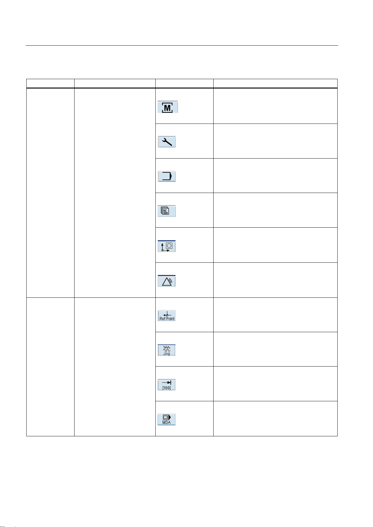
Description
Software user interface
Turning on, reference point
approach
Setup
Manual mode
Automatic mode
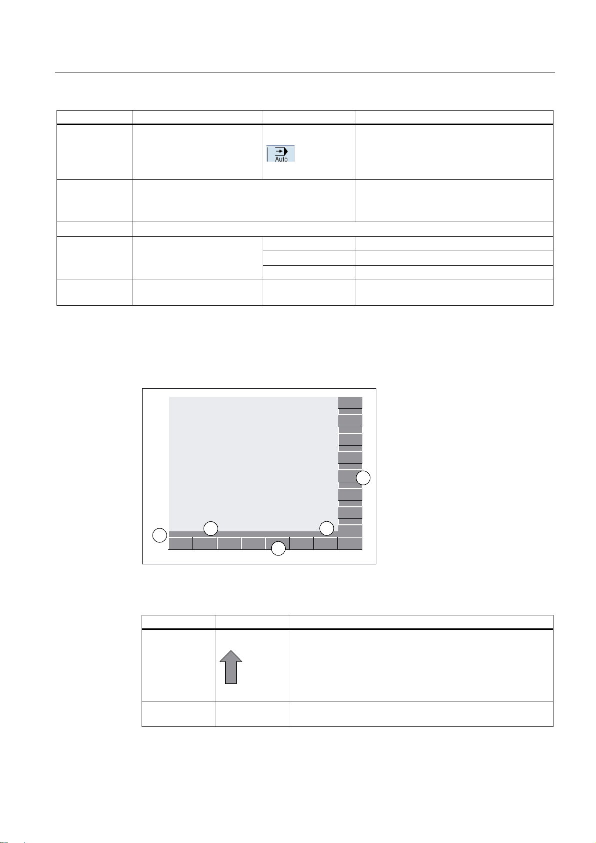
Part programming
System
Cycles
Programming
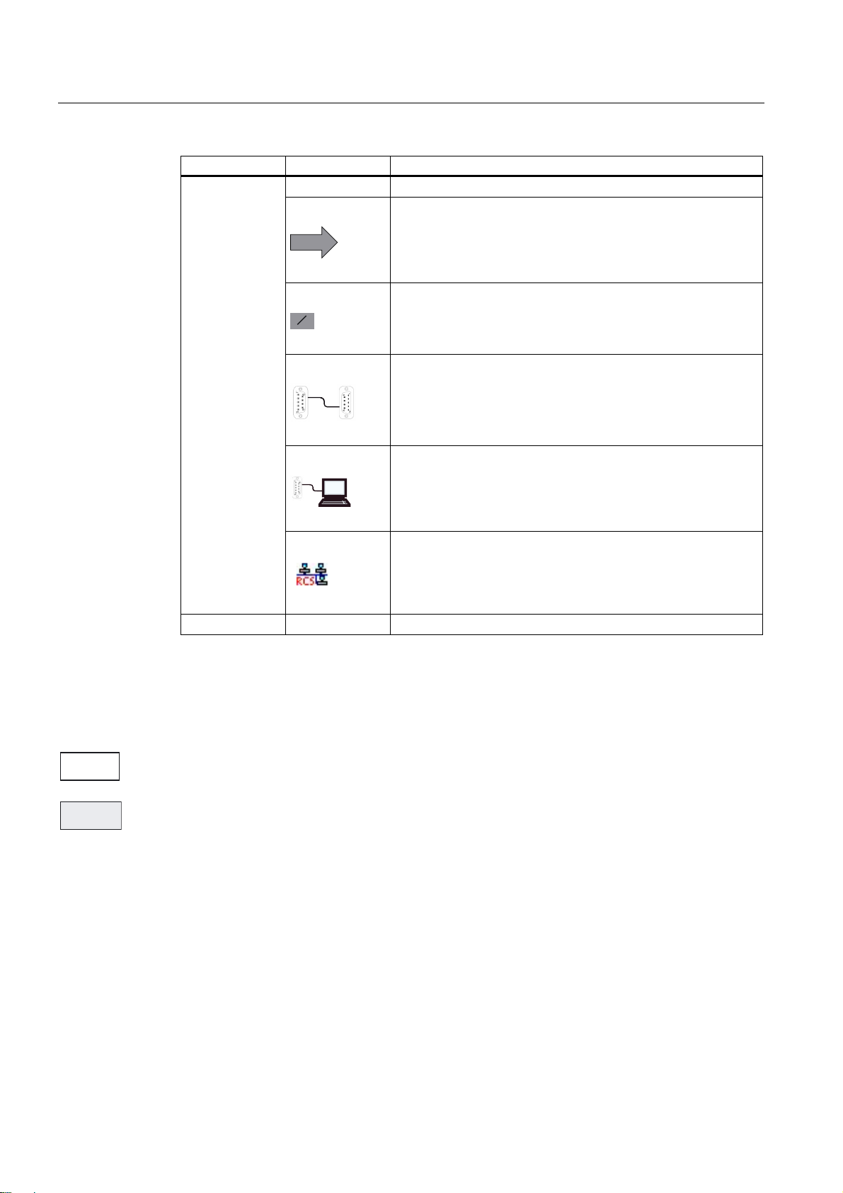
Network operation
Data Backup
PLC diagnostics
Appendix
1
2
3
4
5
6
7
8
9
10
11
12
13
A
07/2009
6FC5398-5CP10-1BA0
Page 2
Legal information
Legal information
Warning notice system
This manual contains notices you have to observe in order to ensure your personal safety, as well as to prevent
damage to property. The notices referring to your personal safety are highlighted in the manual by a safety alert
symbol, notices referring only to property damage have no safety alert symbol. These notices shown below are
graded according to the degree of danger.
DANGER
indicates that death or severe personal injury will result if proper precautions are not taken.
WARNING
indicates that death or severe personal injury may result if proper precautions are not taken.
CAUTION
with a safety alert symbol, indicates that minor personal injury can result if proper precautions are not taken.
CAUTION
without a safety alert symbol, indicates that property damage can result if proper precautions are not taken.
NOTICE
indicates that an unintended result or situation can occur if the corresponding information is not taken into
account.
If more than one degree of danger is present, the warning notice representing the highest degree of danger will
be used. A notice warning of injury to persons with a safety alert symbol may also include a warning relating to
property damage.
Qualified Personnel
The product/system described in this documentation may be operated only by personnel qualified for the specific
task in accordance with the relevant documentation for the specific task, in particular its warning notices and
safety instructions. Qualified personnel are those who, based on their training and experience, are capable of
identifying risks and avoiding potential hazards when working with these products/systems.
Proper use of Siemens products
Note the following:
WARNING
Siemens products may only be used for the applications described in the catalog and in the relevant technical
documentation. If products and components from other manufacturers are used, these must be recommended
or approved by Siemens. Proper transport, storage, installation, assembly, commissioning, operation and
maintenance are required to ensure that the products operate safely and without any problems. The permissible
ambient conditions must be adhered to. The information in the relevant documentation must be observed.
Trademarks
All names identified by ® are registered trademarks of the Siemens AG. The remaining trademarks in this
publication may be trademarks whose use by third parties for their own purposes could violate the rights of the
owner.
Disclaimer of Liability
We have reviewed the contents of this publication to ensure consistency with the hardware and software
described. Since variance cannot be precluded entirely, we cannot guarantee full consistency. However, the
information in this publication is reviewed regularly and any necessary corrections are included in subsequent
editions.
Siemens AG
Industry Sector
Postfach 48 48
90026 NÜRNBERG
GERMANY
Ordernumber: 6FC5398-5CP10-1BA0
Ⓟ 08/2009
Copyright © Siemens AG 2009.
Technical data subject to change
Page 3

Preface
Structure of the documentation
The SINUMERIK documentation is organized in 3 parts:
● General documentation
● User documentation
● Manufacturer/service documentation
Information on the following topics is available at
http://www.siemens.com/motioncontrol/docu:
● Ordering documentation
Here you can find an up-to-date overview of publications.
● Downloading documentation
Links to more information for downloading files from Service & Support.
Target group
Benefits
● Researching documentation online
Information on DOConCD and direct access to the publications in DOConWEB.
● Compiling individual documentation on the basis of Siemens contents with the My
Documentation Manager (MDM), refer to http://www.siemens.com/mdm
My Documentation Manager provides you with a range of features for generating your
own machine documentation.
● Training and FAQs
Information on the range of training courses and FAQs (frequently asked questions) are
available via the page navigation.
This publication is intended for programmers, planning engineers, machine operators and
system operators.
With the Programming and Operating Manual, the target group can develop, write, test and
debug programs and software user interfaces.
In addition, it enables the target group to operate the hardware and software of a machine.
Surface grinding
Programming and Operating Manual, 07/2009, 6FC5398-5CP10-1BA0
3
Page 4
Preface
Standard scope
This documentation only describes the functionality of the standard version. Extensions or
changes made by the machine tool manufacturer are documented by the machine tool
manufacturer.
Other functions not described in this documentation might be executable in the control. This
does not, however, represent an obligation to supply such functions with a new control or
when servicing.
For the sake of simplicity, this documentation does not contain all detailed information about
all types of the product and cannot cover every conceivable case of installation, operation, or
maintenance.
Technical support
If you have any technical questions, please contact our hotline:
Europe / Africa
Phone +49 180 5050 222
Fax +49 180 5050 223
€ 0.14/min. from German landlines, mobile phone prices may differ.
Internet http://www.siemens.com/automation/support-request
America
Phone +1 423 262 2522
Fax +1 423 262 2200
E-mail mailto:techsupport.sea@siemens.com
Asia/Pacific
Phone +86 1064 757575
Fax +86 1064 747474
E-mail mailto:support.asia.automation@siemens.com
Note
Country telephone numbers for technical support are provided under the following Internet
address:
http://www.automation.siemens.com/partner
Surface grinding
4 Programming and Operating Manual, 07/2009, 6FC5398-5CP10-1BA0
Page 5

Preface
Questions regarding documentation
If you have any queries (suggestions, corrections) in relation to this documentation, please
fax or e-mail us:
Fax +49 9131 98 2176
E-mail mailto:docu.motioncontrol@siemens.com
A fax form is available in the appendix of this document.
SINUMERIK Internet address
http://www.siemens.com/sinumerik
EC Declaration of Conformity
The EC Declaration of Conformity for the EMC Directive can be found/obtained
● on the internet:
http://support.automation.siemens.com
under the product/order No. 15263595
● at the relevant regional office of the I DT MC Business Unit of Siemens AG.
Surface grinding
Programming and Operating Manual, 07/2009, 6FC5398-5CP10-1BA0
5
Page 6

Preface
Surface grinding
6 Programming and Operating Manual, 07/2009, 6FC5398-5CP10-1BA0
Page 7

Table of contents
Preface ......................................................................................................................................................
1 Description...............................................................................................................................................
1.1 Control and display elements.......................................................................................................
1.2 Error and status displays .............................................................................................................
1.3 Key definition of the full CNC keyboard (vertical format).............................................................
1.4 Key definition of the machine control panel .................................................................................
1.5 Coordinate systems .....................................................................................................................
2 Software user interface............................................................................................................................
2.1 Screen layout ...............................................................................................................................
2.2 Operating areas ...........................................................................................................................
2.3 The help system...........................................................................................................................
3 Turning on, reference point approach......................................................................................................
4 Setup.......................................................................................................................................................
4.1 Entering tools and tool offsets......................................................................................................
4.2 Create new tool............................................................................................................................
4.3 Register dresser...........................................................................................................................
4.4 Sense workpiece..........................................................................................................................
3
13
13
14
15
17
19
23
23
27
29
31
33
33
35
44
46
4.5 Shaping/dressing .........................................................................................................................
4.6 Manual grinding ...........................................................................................................................
4.7 Program setting data....................................................................................................................
4.8 Arithmetic parameter R ................................................................................................................
4.9 User data......................................................................................................................................
5 Manual mode...........................................................................................................................................
5.1 Manual mode ...............................................................................................................................
5.2 JOG mode - "Position" operating area.........................................................................................
5.2.1 JOG mode....................................................................................................................................
5.2.2 Assigning handwheels .................................................................................................................
5.3 MDA mode (manual input) "Position" operating area .................................................................
5.3.1 Teach In .......................................................................................................................................
6 Automatic mode.......................................................................................................................................
6.1 Automatic mode ...........................................................................................................................
6.2 Machining offset...........................................................................................................................
6.3 Selection and start of a part program ..........................................................................................
Surface grinding
Programming and Operating Manual, 07/2009, 6FC5398-5CP10-1BA0
48
50
54
58
59
61
61
62
62
65
66
69
73
73
78
79
7
Page 8

Table of contents
6.4 Block search................................................................................................................................ 81
6.5 Simultaneous recording ..............................................................................................................
6.6 Stop / cancel a part program.......................................................................................................
6.7 Reapproach after cancellation ....................................................................................................
6.8 Repositioning after interruption ...................................................................................................
6.9 Execute from external .................................................................................................................
7 Part programming....................................................................................................................................
7.1 Part programming overview ........................................................................................................
7.2 Enter new program......................................................................................................................
7.3 Editing the part program..............................................................................................................
8 System...................................................................................................................................................
8.1 "System" operating area ...........................................................................................................
8.2 SYSTEM - "Start-up" softkeys...................................................................................................
8.3 SYSTEM - "Machine data" softkeys..........................................................................................
8.4 SYSTEM - "Service display" .....................................................................................................
8.4.1 Action log...................................................................................................................................
8.4.2 Servo trace................................................................................................................................
8.4.3 Version/HMI details...................................................................................................................
8.4.4 Service MSG .............................................................................................................................
8.5 SYSTEM - "PLC" softkeys ........................................................................................................
84
87
88
89
90
93
93
97
98
101
101
106
107
114
116
117
121
125
131
8.6 SYSTEM - "Start-up files" softkeys ...........................................................................................
8.7 Alarm display.............................................................................................................................
9 Cycles....................................................................................................................................................
9.1 Overview of cycles ....................................................................................................................
9.2 Cycle requirements ...................................................................................................................
9.3 Programming cycles..................................................................................................................
9.3.1 Call and return conditions .........................................................................................................
9.3.2 Error messages and error handling ..........................................................................................
9.3.2.1 General information...................................................................................................................
9.3.2.2 Error handling within cycles ......................................................................................................
9.3.3 Cycle call and parameter list.....................................................................................................
9.4 Zyklenunterstützung im Programmeditor ..................................................................................
9.5 Z positioning with grinding wheel - CYCLE406.........................................................................
9.6 Safety position - CYCLE407 .....................................................................................................
9.7 3-stage plunge cut oscillation (roughing, finishing and fine-finishing) - CYCLE408 .................
9.8 3-stage surface grinding (roughing, finishing and fine-finishing) - CYCLE409 .........................
9.9 Dressing and profiling - CYCLE416 ..........................................................................................
9.10 Oscillating plunge cutting - CYCLE426.....................................................................................
9.11 Surface grinding with continuous infeed - CYCLE427..............................................................
139
144
147
147
149
150
150
151
151
151
152
156
158
160
161
165
168
170
173
Surface grinding
8 Programming and Operating Manual, 07/2009, 6FC5398-5CP10-1BA0
Page 9

Table of contents
9.12 Surface grinding with intermittent infeed - CYCLE428 ..............................................................176
9.13 Profile grinding - CYCLE429......................................................................................................
9.14 Dressing with profile roller - CYCLE430 ....................................................................................
9.15 Selection of the grinding wheel peripheral speed - CYCLE446.................................................
10 Programming.........................................................................................................................................
10.1 Fundamental principles of NC programming .............................................................................
10.1.1 Program names .........................................................................................................................
10.1.2 Program structure ......................................................................................................................
10.1.3 Word structure and address.......................................................................................................
10.1.4 Block format ...............................................................................................................................
10.1.5 Fonts ..........................................................................................................................................
10.1.6 List of instructions ......................................................................................................................
10.2 Positional data ...........................................................................................................................
10.2.1 Programming dimensions ..........................................................................................................
10.2.2 Plane selection: G17 to G19......................................................................................................
10.2.3 Absolute/incremental dimensioning: G90, G91, AC, IC.............................................................
10.2.4 Dimensions in metric units and inches: G71, G70, G710, G700...............................................
10.2.5 Polar coordinates, pole definition: G110, G111, G112 ..............................................................
10.2.6 Programmable work offset: TRANS, ATRANS ..........................................................................
10.2.7 Programmable rotation: ROT, AROT.........................................................................................
10.2.8 Programmable scaling factor: SCALE, ASCALE .......................................................................
10.2.9 Programmable mirroring: MIRROR, AMIRROR ........................................................................
10.2.10 Workpiece clamping - settable work offset: G54 to G59, G500, G53, G153.............................
10.2.11 Programmable working area limitation: G25, G26, WALIMON, WALIMOF ..............................
179
182
184
185
185
185
185
186
187
189
190
201
201
202
203
205
206
208
209
211
212
214
216
10.3 Axis movements.........................................................................................................................
10.3.1 Linear interpolation with rapid traverse: G0 ...............................................................................
10.3.2 Linear interpolation with feedrate: G1........................................................................................
10.3.3 Circular interpolation: G2, G3 ....................................................................................................
10.3.4 Circular interpolation via intermediate point: CIP.......................................................................
10.3.5 Circle with tangential transition: CT ...........................................................................................
10.3.6 Fixed point approach: G75.........................................................................................................
10.3.7 Reference point approach: G74.................................................................................................
10.3.8 Measuring with touch-trigger probe: MEAS, MEAW..................................................................
10.3.9 Feedrate F..................................................................................................................................
10.3.10 Exact stop / continuous-path control mode: G9, G60, G64 .......................................................
10.3.11 Acceleration pattern: BRISK, SOFT...........................................................................................
10.3.12 Percentage acceleration override: ACC ....................................................................................
10.3.13 Fourth axis .................................................................................................................................
10.3.14 Dwell time: G4............................................................................................................................
10.3.15 Travel to fixed stop.....................................................................................................................
10.4 Spindle movement .....................................................................................................................
10.4.1 Spindle speed S, directions of rotation ......................................................................................
10.4.2 Spindle speed limitation: G25, G26 ...........................................................................................
10.4.3 Spindle positioning: SPOS.........................................................................................................
10.4.4 Gear stages................................................................................................................................
10.4.5 2. Spindle ...................................................................................................................................
10.5 Special functions ........................................................................................................................
10.5.1 Constant cutting rate: G96, G97 ................................................................................................
10.5.2 Rounding, chamfer.....................................................................................................................
10.5.3 Contour definition programming.................................................................................................
218
218
220
222
228
229
230
231
232
234
235
238
239
240
241
242
245
245
246
247
248
248
250
250
252
255
Surface grinding
Programming and Operating Manual, 07/2009, 6FC5398-5CP10-1BA0
9
Page 10

Table of contents
10.6 Tool and tool offset.................................................................................................................... 257
10.6.1 General Information ..................................................................................................................
10.6.2 Tool T ........................................................................................................................................
10.6.3 Tool offset number D.................................................................................................................
10.6.4 Selecting the tool radius compensation: G41, G42 ..................................................................
10.6.5 Corner behavior: G450, G451...................................................................................................
10.6.6 Tool radius compensation OFF: G40........................................................................................
10.6.7 Special cases of the tool radius compensation.........................................................................
10.6.8 Example of tool radius compensation .......................................................................................
257
258
259
261
264
265
266
267
10.7 Miscellaneous function M..........................................................................................................
10.8 H function ..................................................................................................................................
10.9 Arithmetic parameters (R variables), LUD and PLC variables..................................................
10.9.1 Arithmetic parameter R .............................................................................................................
10.9.2 Local User Data (LUD)..............................................................................................................
10.9.3 Reading and writing PLC variables...........................................................................................
10.10 Program jumps..........................................................................................................................
10.10.1 Jump destination for program jumps.........................................................................................
10.10.2 Unconditional program jumps ...................................................................................................
10.10.3 Conditional program jumps .......................................................................................................
10.10.4 Program example for jumps......................................................................................................
10.11 Subroutine technique ................................................................................................................
10.11.1 General information...................................................................................................................
10.11.2 Calling machining cycles...........................................................................................................
10.12 Timers and workpiece counters ................................................................................................
10.12.1 Runtime timer............................................................................................................................
10.12.2 Workpiece counter ....................................................................................................................
10.13 Multiple feedrate values in one block........................................................................................
10.14 Oscillation..................................................................................................................................
11 Network operation..................................................................................................................................
11.1 Network operation prerequisites ...............................................................................................
268
270
271
271
274
276
277
277
278
279
281
283
283
286
287
287
289
291
293
297
297
11.2 RCS802 tool..............................................................................................................................
11.3 Network operation .....................................................................................................................
11.3.1 Configuring the network connection..........................................................................................
11.3.2 User management.....................................................................................................................
11.3.3 User log in - RCS log in.............................................................................................................
11.3.4 Working on the basis of a network connection .........................................................................
11.3.5 Sharing directories ....................................................................................................................
11.3.6 Connecting / disconnecting network drives...............................................................................
12 Data Backup..........................................................................................................................................
12.1 Data transfer via RS232 interface .............................................................................................
12.2 Creating / reading in / reading out a start-up archive................................................................
12.3 Reading in / reading out PLC projects ......................................................................................
12.4 Copying and pasting files ..........................................................................................................
13 PLC diagnostics.....................................................................................................................................
13.1 Screen layout ............................................................................................................................
Surface grinding
298
303
304
306
307
308
309
310
313
313
315
318
319
321
322
10 Programming and Operating Manual, 07/2009, 6FC5398-5CP10-1BA0
Page 11

Table of contents
13.2 Operating options.......................................................................................................................323
A Appendix................................................................................................................................................
A.1 User data....................................................................................................................................
A.2 Parameter tables of the tool data...............................................................................................
A.3 Miscellaneous ............................................................................................................................
A.3.1 Pocket calculator........................................................................................................................
A.3.2 Editing Asian characters ............................................................................................................
A.4 Feedback on the documentation................................................................................................
A.5 Overview ....................................................................................................................................
Glossary ................................................................................................................................................
335
335
338
343
343
345
349
351
353
Index...................................................................................................................................................... 355
Surface grinding
Programming and Operating Manual, 07/2009, 6FC5398-5CP10-1BA0
11
Page 12

Table of contents
Surface grinding
12 Programming and Operating Manual, 07/2009, 6FC5398-5CP10-1BA0
Page 13
Description
1.1 Control and display elements
Operator control elements
The defined functions are called up via the horizontal and vertical softkeys. For a description,
please refer to this manual:
1
9HUWLFDOVRIWNH\V
Figure 1-1 CNC operator panel
+RUL]RQWDOVRIWNH\V
Surface grinding
Programming and Operating Manual, 07/2009, 6FC5398-5CP10-1BA0
13
Page 14
Description
1.2 Error and status displays
1.2 Error and status displays
LED displays on the CNC operator panel (PCU)
The following LEDs are installed on the CNC operator panel.
(55 5'< 1& &)
The individual LEDs and their functions are described in the table below.
Table 1- 1 Status and error displays
LED Significance
ERR (red) Serious error, remedy through power OFF/ON
RDY (green) Ready for operation
NC (yellow) Signoflife monitoring
CF (yellow) Reading from/writing to CF card
References
You can find information on error description in the SINUMERIK 802D sl Diagnostics Manual
Surface grinding
14 Programming and Operating Manual, 07/2009, 6FC5398-5CP10-1BA0
Page 15
Description
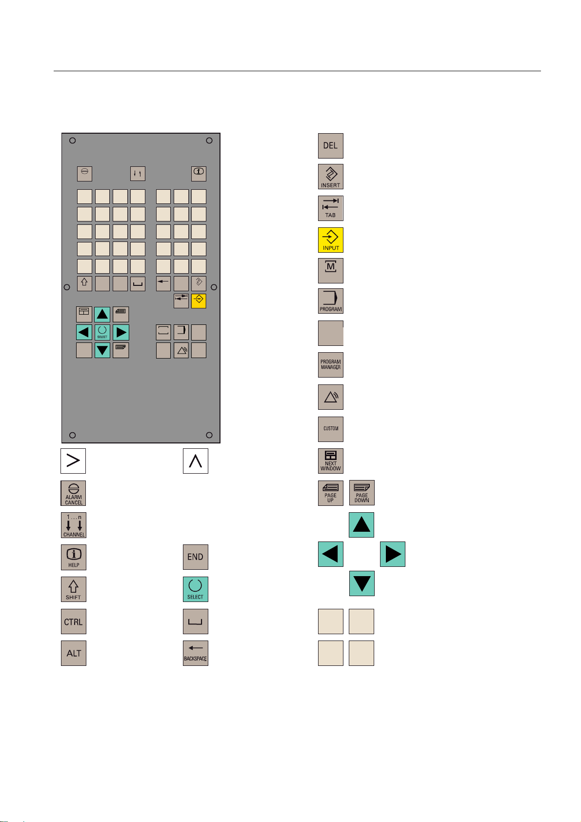
1.3 Key definition of the full CNC keyboard (vertical format)
1.3 Key definition of the full CNC keyboard (vertical format)
'HOHWHNH\
$/$50
&$1&(/
2
8
;
0
>
)
6+,)7
1(;7
:,1'2:
(1'
Q
&+$11(/
1
9
<
$
,
-
6
'
675*
?
(
*
:
=
ಱ
.
7
_
+
$/7
3$*(
83
3$*(
'2:1
3
4
&
@
5
/
"
%
%$&.63$&(
0
326,7,21
3URJUDP
0DQDJHU
#
'(/
7$%
352*5$0
6<67(0
$/$50
+(/3
!
,16(57
,1387
2))6(7
3$5$0
&86720
,QVHUWNH\
7DEXODWRU
(17(5,QSXWNH\
326,7,21RSHUDWLQJDUHDNH\3RVLWLRQ
326,7,21
RSHUDWLQJDUHD
352*5$0RSHUDWLQJDUHDNH\
3URJUDPRSHUDWLQJDUHD
2))6(7
3$5$0
2))6(73$5$0RSHUDWLQJDUHDNH\
3DUDPHWHURSHUDWLQJDUHD
352*5$00$1$*(5RSHUDWLQJDUHDNH\
3URJUDP0DQDJHURSHUDWLQJDUHD
6<67(0
$/$50
6<67(0$/$50RSHUDWLQJDUHDNH\
6\VWHP$ODUPRSHUDWLQJDUHD
&86720RSHUDWLQJDUHD
8VHURSHUDWLQJDUHD
(7&NH\
$FNQRZOHGJHDODUPNH\
1RIXQFWLRQ
,QIRNH\
6KLIWNH\
&RQWURONH\
$/7NH\
5HFDOONH\
6HOHFWLRQNH\WRJJOHNH\
6SDFH
'HOHWHNH\EDFNVSDFH
QRWDVVLJQHG
6FUROONH\V
&XUVRUNH\V
$
:
=
-
$OSKDQXPHULFNH\V
'RXEOHDVVLJQPHQWDWWKH6KLIWOHYHO
1XPHULFNH\V
'RXEOHDVVLJQPHQWDWWKH6KLIWOHYHO
Surface grinding
Programming and Operating Manual, 07/2009, 6FC5398-5CP10-1BA0
15
Page 16
Description
1.3 Key definition of the full CNC keyboard (vertical format)
Hot keys
In the part program editor and in the input fields of the HMI, the following functions can be
carried out with certain key combinations on the full CNC keyboard:
Keystroke combination Function
<CTRL> and <C> Copy selected text
<CTRL> and <B> Select text
<CTRL> and <X> Cut selected text
<CTRL> and <V> Paste copied text
<ALT> and <L> Changeover to small letters
<ALT> and <H> or <HELP> key Call help system
<ALT> and <S> Switch-in and switch-out the Editor for Asian
characters
Surface grinding
16 Programming and Operating Manual, 07/2009, 6FC5398-5CP10-1BA0
Page 17
Description
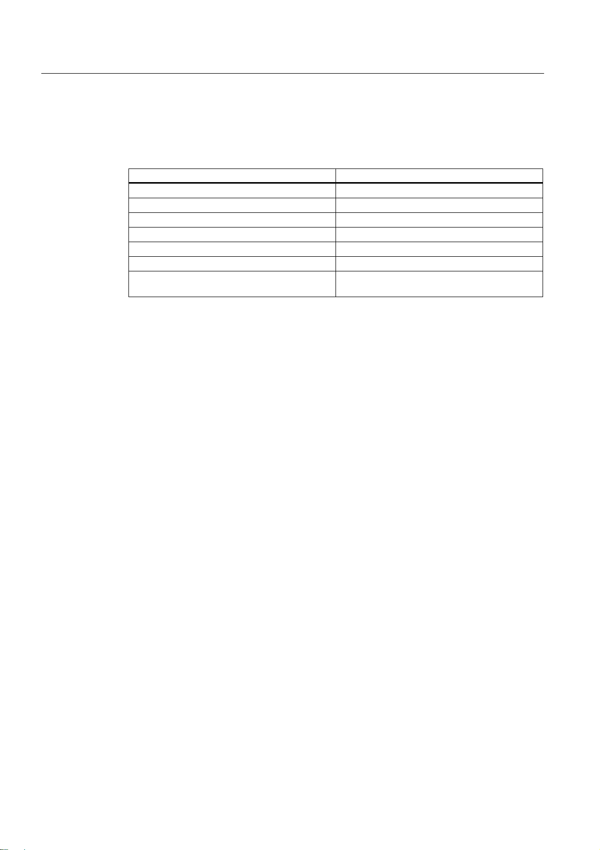
1.4 Key definition of the machine control panel
1.4 Key definition of the machine control panel
8VHUGHILQHGNH\ZLWK/('
8VHUGHILQHGNH\ZLWKRXW/('
,1&5(0(17
,QFUHPHQW
-2*
5()(5(1&(32,17
5HIHUHQFHSRLQW
$8720$7,&
6,1*/(%/2&.
6LQJOHEORFN
0$18$/'$7$
0DQXDOLQSXW
63,1'/(67$57&&:
&RXQWHUFORFNZLVH
;
<
=
=
<
;
63,1'/(6723
63,1'/(67$57&:
&ORFNZLVH
5$3,'75$9(56(29(5/$<
5(6(7
;
&<&/(6723
1&6723
<
&<&/(67$57
1&67$57
=
(0(5*(1&<6723
6SLQGOH6SHHG2YHUULGH
6SLQGOHRYHUULGH
;
<
=
5DSLGWUDYHUVHRYHUULGH
;D[LV
<D[LV
=D[LV
)HHGUDWHRYHUULGH
)HHGUDWHFRQWURO
Surface grinding
Programming and Operating Manual, 07/2009, 6FC5398-5CP10-1BA0
17
Page 18

Description
1.4 Key definition of the machine control panel
Note
This documentation assumes an 802D standard machine control panel (MCP). Should you
use a different MCP, the operation may be other than described herein.
Surface grinding
18 Programming and Operating Manual, 07/2009, 6FC5398-5CP10-1BA0
Page 19
Description
1.5 Coordinate systems
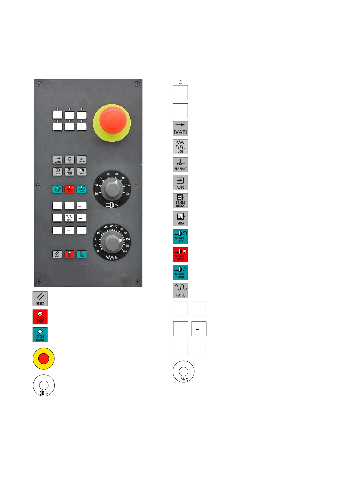
1.5 Coordinate systems
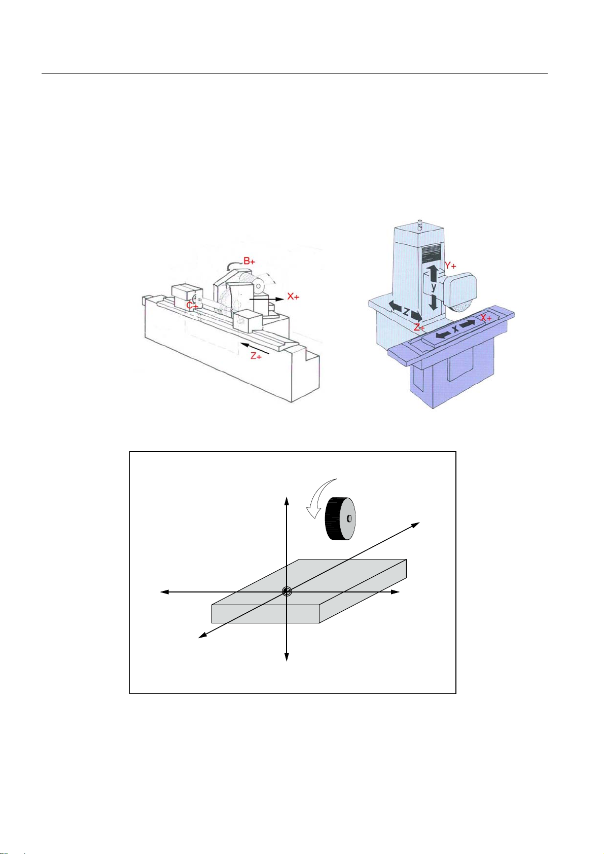
As a rule, a coordinate system is formed from three mutually perpendicular coordinate axes.
The positive directions of the coordinate axes are defined using the so-called "3-finger rule"
of the right hand. The coordinate system is related to the workpiece and programming takes
place independently of whether the tool or the workpiece is being traversed. When
programming, it is always assumed that the tool traverses relative to the coordinate system
of the workpiece, which is intended to be stationary.
=
<
<
90°
90°
90°
;
=
;
Figure 1-2 Determination of the axis directions to one another; coordinate system for programming
Surface grinding
Programming and Operating Manual, 07/2009, 6FC5398-5CP10-1BA0
19
Page 20
Description
1.5 Coordinate systems
Machine coordinate system (MCS)
The orientation of the coordinate system relative to the machine depends on the respective
machine type. It can be rotated in different positions.
The directions of the axes follow the "3-finger rule" of the right hand. Seen from in front of the
machine, the middle finger of the right hand points in the opposite direction to the infeed of
the main spindle.
Figure 1-3 MCS for grinding (cylindrical grinding machine, surface grinding machine)
<
;
=
;
<
=
Figure 1-4 Machine coordinate system
Surface grinding
20 Programming and Operating Manual, 07/2009, 6FC5398-5CP10-1BA0
Page 21
Description
1.5 Coordinate systems
The origin of this coordinate system is the machine zero.
This point is only a reference point which is defined by the machine manufacturer. It does not
have to be approachable.
The traversing range of the machine axes can be in the negative range.
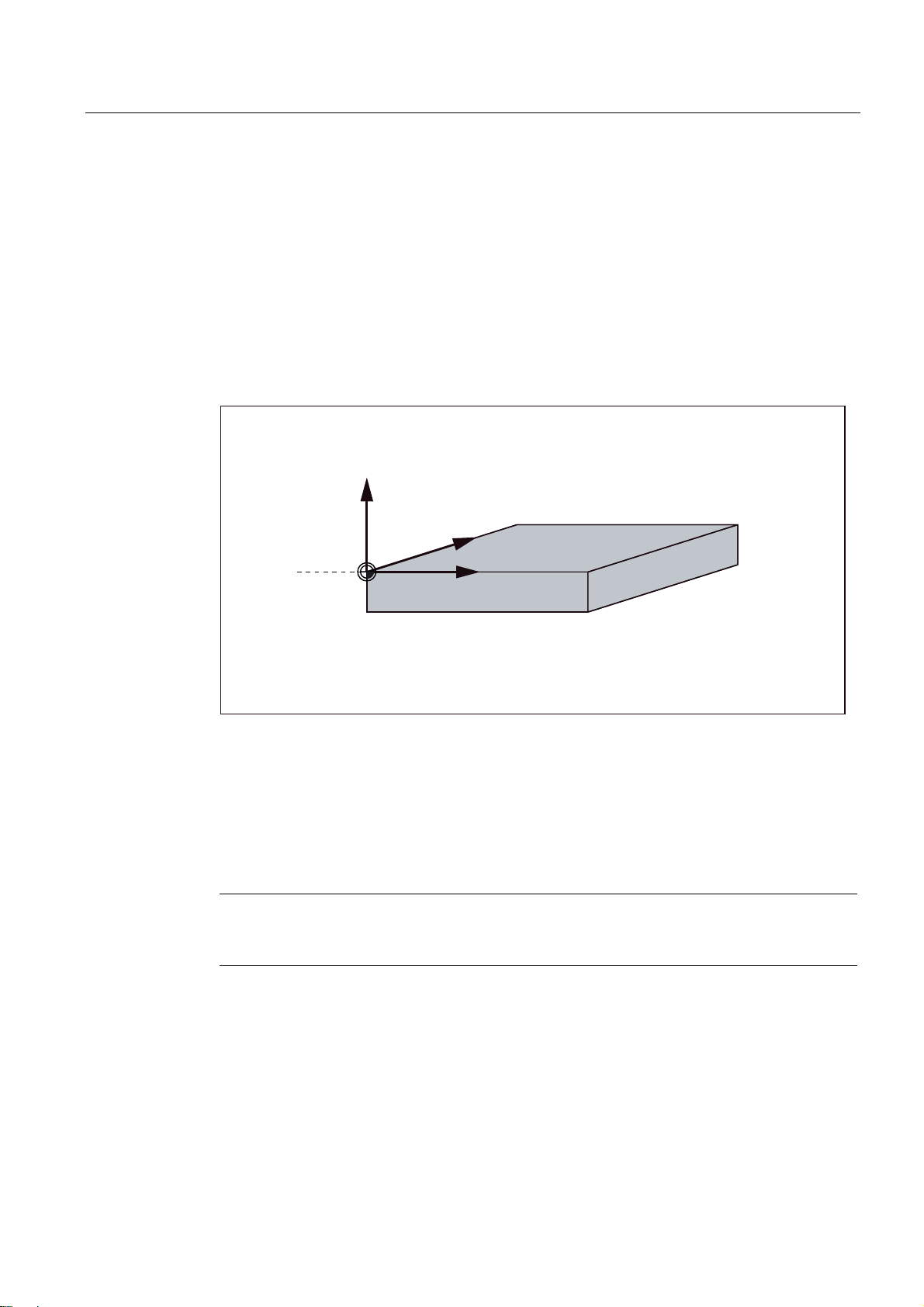
Workpiece coordinate system (WCS)
To describe the geometry of a workpiece in the workpiece program, a right-handed, rightangled coordinate system is also used.
The workpiece zero can be freely selected by the programmer in the Y axis. In the Z axis, it
lies in the turning center.
<
;
Figure 1-5 Workpiece Coordinate System
Relative coordinate system (REL)
In addition to the machine and workpiece coordinate systems, the control system provides a
relative coordinate system. This coordinate system is used for setting reference points that
can be freely selected and have no influence on the active workpiece coordinate system. All
axis movements are displayed relative to these reference points.
Note
The actual value in the associated coordinate system can be activated and displayed in the
"Position" operating area using the "MKS/WKS REL" vertical softkey.
:
: ZRUNSLHFH]HUR
=
Surface grinding
Programming and Operating Manual, 07/2009, 6FC5398-5CP10-1BA0
21
Page 22
Description
1.5 Coordinate systems
Clamping the workpiece
For machining, the workpiece is clamped on the machine. The workpiece must be aligned
such that the axes of the workpiece coordinate system run in parallel with those of the
machine. Any resulting offset of the machine zero with reference to the workpiece zero is
determined along the Y axis and entered in a data area intended for the settable work offset.
In the NC program, this offset is activated during program execution, e.g. using a
programmed G54.
<
PDFKLQH
<
ZRUNSLHFH
:
HJ*
0
Figure 1-6 Workpiece on the machine
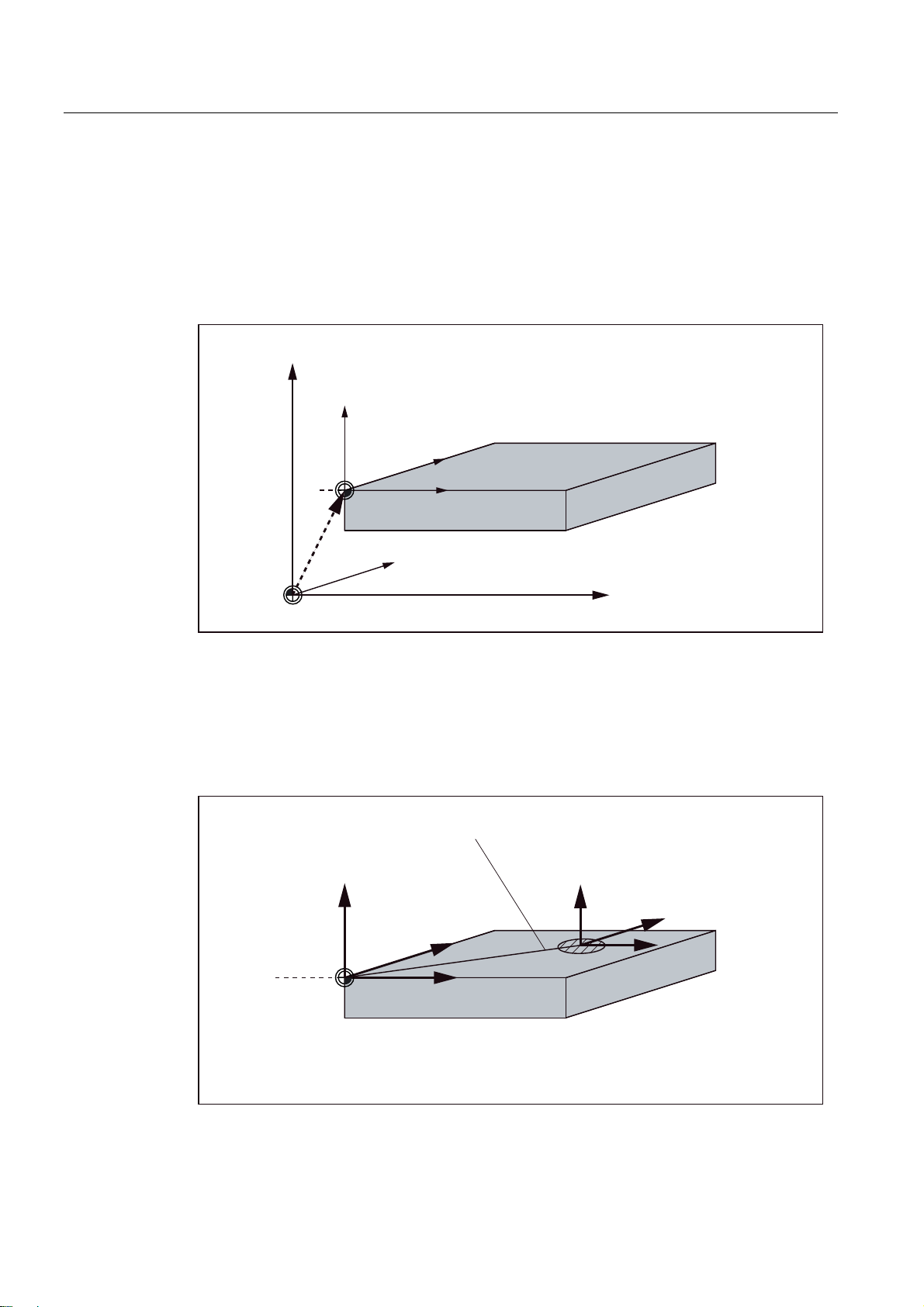
Current workpiece coordinate system
The programmed work offset TRANS can be used to generate an offset with reference to the
workpiece coordinate system. resulting in the current workpiece coordinate system (see
Section "Programmable work offset: TRANS").
;
PDFKLQH
: ZRUNSLHFH]HUR
0 PDFKLQH]HUR
;
=
=
PDFKLQH
3URJUDPPDEOHRIIVHW
<
;
:
: ZRUNSLHFH]HUR
75$16
=
<
&XUUHQW
;
=
Figure 1-7 Coordinates on the workpiece; current workpiece coordinate system
Surface grinding
22 Programming and Operating Manual, 07/2009, 6FC5398-5CP10-1BA0
Page 23
Software user interface
2.1 Screen layout
6WDWXVDUHD
$SSOLFDWLRQDUHD
7LS
DQGVRIWNH\DUHD
Figure 2-1 Screen layout
2
Status area
The screen is divided into the following main areas:
● Status area
● Application area
● Note and softkey area
Figure 2-2 Status area
Surface grinding
Programming and Operating Manual, 07/2009, 6FC5398-5CP10-1BA0
23
Page 24
Software user interface
2.1 Screen layout
Table 2- 1 Explanation of the screen controls in the status area
Numbering Display Icon Significance
① Active operating area
Position (operating area key <POSITION>)
System (operating area key <SYSTEM>)
Program (operating area key <PROGRAM>)
Program Manager (operating area key
<PROGRAM MANAGER>)
Parameter (operating area key <OFFSET
PARAM>)
Alarm (operating area key <ALARM>)
② Active mode
Approaching a reference point
JOG
JOG INC; 1 INC, 10 INC, 100 INC, 1000 INC,
VAR INC
(incremental evaluation in the JOG mode)
MDA
Surface grinding
24 Programming and Operating Manual, 07/2009, 6FC5398-5CP10-1BA0
Page 25
Software user interface
2.1 Screen layout
Numbering Display Icon Significance
AUTOMATIC
③ Alarm and message line In addition, the following is displayed:
1. Alarm number with alarm text, or
2. Message text
④ Selected part program (main program)
⑤ Program state
⑥ Program control in automatic
mode
RESET Program canceled / default state
RUN Program is running
STOP Program stopped
Note and softkey area
Figure 2-3 Note and softkey area
Table 2- 2 Explanation of the screen controls in the note and softkey area
Screen item Display Significance
①
RECALL symbol
Pressing the <RECALL> key lets you return to the higher menu
level.
② Information line
Displays notes and information for the operator and fault states
Surface grinding
Programming and Operating Manual, 07/2009, 6FC5398-5CP10-1BA0
25
Page 26
Software user interface
2.1 Screen layout
Screen item Display Significance
③
HMI status information
ETC is possible (pressing this key displays the horizontal
softkey bar providing further functions.)
ಯ/ಯ
Mixed notation active (uppercase/lowercase letters)
RS232 connection active
Connection to commissioning and diagnostic tools (e.g.
Programming Tool 802) active
RCS network connection active
④ Softkey bar vertical and horizontal
Display of the softkeys in the document
To make the softkeys easier to locate, the horizontal and vertical softkeys are displayed in
different basic colors.
Horizontal softkey
Vertical softkey
Surface grinding
26 Programming and Operating Manual, 07/2009, 6FC5398-5CP10-1BA0
Page 27
Software user interface
2.2 Operating areas
2.2 Operating areas
The functions of the control system can be carried out in the following operating areas:
2))6(7
3$5$0
6<67(0
$/$50
6<67(0
$/$50
POSITION
OFFSET PARAM Entering the compensation values and setting
PROGRAM
PROGRAM
MANAGER
SYSTEM
ALARM
CUSTOM
Machine operation
data
Creation of part programs
Part program directory
Diagnostics, commissioning
Alarm and message lists
Users can call their own application
To change to another operating area, press the relevant key on the CNC full keyboard (hard
key).
Surface grinding
Programming and Operating Manual, 07/2009, 6FC5398-5CP10-1BA0
27
Page 28

Software user interface
2.2 Operating areas
Protection levels
The SINUMERIK 802D sl provides a concept of protection levels for enabling data areas.
The control system is delivered with default passwords for the protection levels 1 to 3.
Protection level 1 Experts password
Protection level 2 Manufacturer password
Protection level 3 User password
These control the various access rigths.
In the menus listed below the input and modification of data depends on the protection level
set:
● Tool offsets
● Work offsets
● Setting data
● RS232 settings
● Program creation / program correction
Surface grinding
28 Programming and Operating Manual, 07/2009, 6FC5398-5CP10-1BA0
Page 29
Software user interface
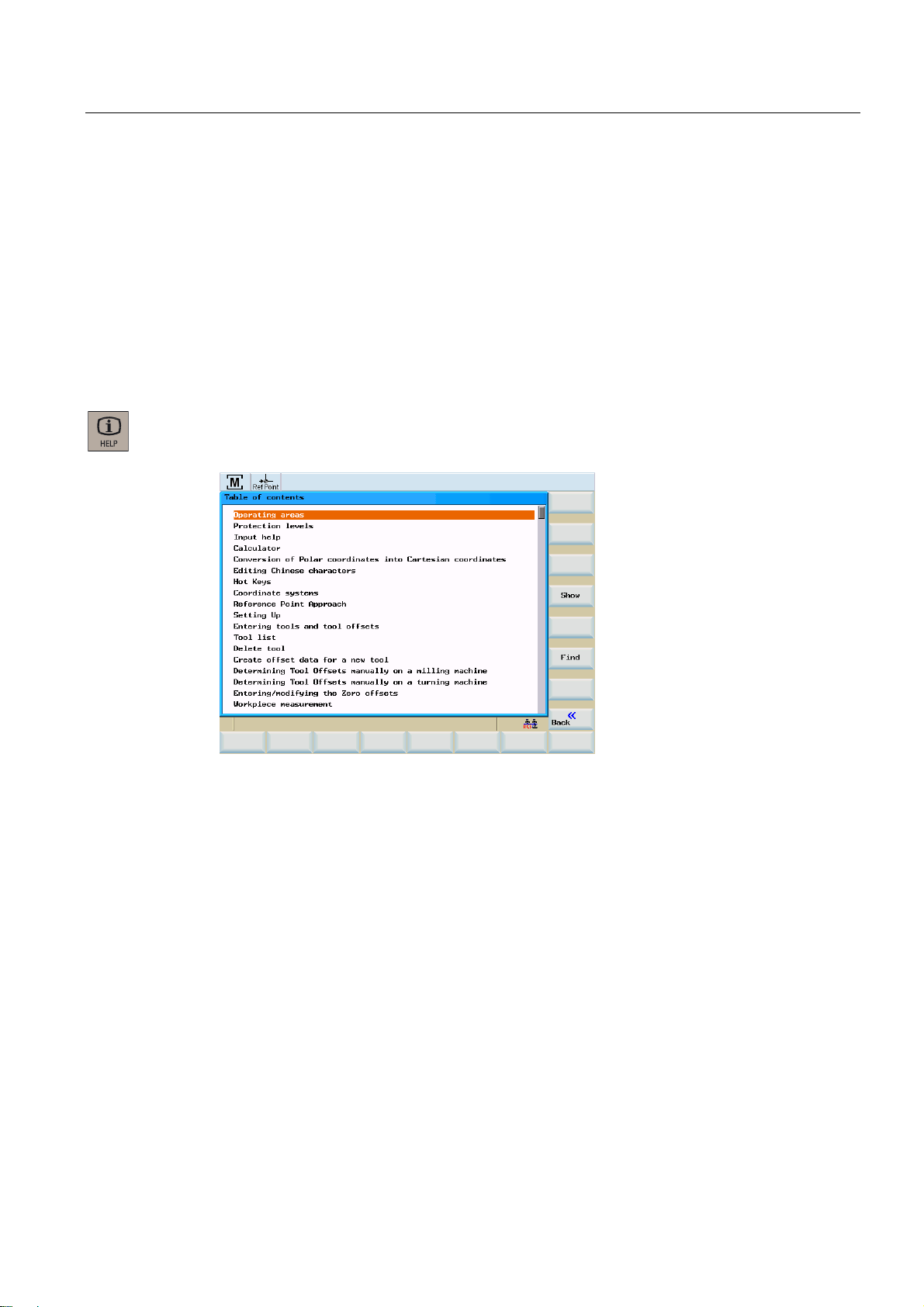
2.3 The help system
2.3 The help system
Comprehensive online help is stored in the control system. Some help topics are:
● Product brief of all important operating functions
● Overview and product brief of the NC commands
● Explanation of the drive parameters
● Explanation of the drive alarms
Operating sequence
You can call the help system from any operating area either by pressing the Info key or by
using the key combination <ALT+H>.
Figure 2-4 Help system: Table of contents
Surface grinding
Programming and Operating Manual, 07/2009, 6FC5398-5CP10-1BA0
29
Page 30
Software user interface
2.3 The help system
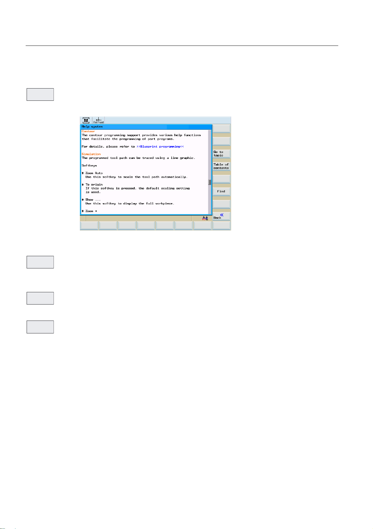
Softkeys
6KRZ
This function opens the selected topic.
Figure 2-5 Help system: Description of the topic
*RWR
7RSLF
Use this function to select cross references. A cross reference is marked by the characters
">>....<<". This softkey is only displayed if a cross reference is displayed in the application
area.
%DFNWR
7RSLF
If you select a cross-reference, the "Back to topic" softkey will also be displayed. Select this
function to go back to the previous screen.
)LQG
Use this function to search for a term in the table of contents. Type the term you are looking
for and start the search process.
Help in the "Program editor" area
The help system offers an explanation for each NC operation. To display the infotext directly,
position the cursor after the appropriate operation and press the Info key. The NC instruction
must be written using uppercase letters.
Surface grinding
30 Programming and Operating Manual, 07/2009, 6FC5398-5CP10-1BA0
Page 31

Turning on, reference point approach
Operating sequence
Note
When you turn on the SINUMERIK 802D sl and the machine, please also observe the
machine documentation, since turning on and reference point approach are machinedependent functions.
First, switch on the power supply for the CNC and the machine.
After the control system has booted, you are in the "Position" operating area, in the
"Reference point approach" mode.
The "Reference point" window is active.
3
Figure 3-1 Reference-point approach start screen
The "Reference point" window displays whether the axes are referenced.
$[LVPXVWEHUHIHUHQFHG
$[LVLVUHIHUHQFHGV\QFKURQL]HG
Surface grinding
Programming and Operating Manual, 07/2009, 6FC5398-5CP10-1BA0
31
Page 32

Turning on, reference point approach
;
<
=
Press the arrow keys.
If you select the wrong approach direction, no motion is carried out.
One after the other, move each axis to the reference point.
You can exit the function by selecting another operating mode (MDA, AUTOMATIC or JOG).
To access the functions described below, you need to select "Jog" mode.
Surface grinding
32 Programming and Operating Manual, 07/2009, 6FC5398-5CP10-1BA0
Page 33

Setup
4.1 Entering tools and tool offsets
Functionality
The "OFFSET PARAM" operating area allows you to store the parameters required for
machine operation.
Operating sequences
2))6(7
3$5$0
7RROOLVW
This function opens the "Tool offset data" window which contains a list of the tools created.
Use the cursor keys and the <Page Up>/<Page Down> keys to navigate in this list.
4
Figure 4-1 Tool list
To input the offsets, position the cursor bar on the tool to be changed and press the <Tool
data> softkey.
Surface grinding
Programming and Operating Manual, 07/2009, 6FC5398-5CP10-1BA0
33
Page 34

Setup
4.1 Entering tools and tool offsets
Softkeys
'HOHWH
GUDP
7RRO
'HOHWH
7RRO
GDWD
1RPLQDO
GLPHQVLRQ
PRQLWRULQJ
*HRPHWU\
GDWD
7HFKQR
ORJ\GDWD
VW
GUHVVHU
([WHQGHG
Clearing the calculated dresser data.
Use this softkey to delete the tool.
Opens a lower-level menu bar offering all functions required to create and display further
tolol data.
This function is used to enter - guided by the menu - the nomiinal dimensions and monitoring
data of the grinding wheel.
This function is used the enter the wheel geometry for the wheel type selected.
This function is used the enter the dressing technology for dressing the wheel type selected.
This function is used to enter/verify the dresser data of the first dresser.
For dressers 2 and 3, it is selected through the respective softkeys.
This function is used to enter/verify all tool data (D1 through D9).
7RRO
FRS\LQJ
)LQG
/DWHVW
7RRO
5SDUD
PHWHUV
6HWWLQJ
GDWD
8VHUGDWD
Use this function to copy an already existing tool.
Use this function to search for a tool by its number.
Use this softkey to create tool compensation data for a new tool.
This function is used to list and, if necessary, modify any R parameters that exist in the
control system.
Input of the setting data.
This function is used to list and, if necessary, modify any user grinding data that exists in the
controller.
Surface grinding
34 Programming and Operating Manual, 07/2009, 6FC5398-5CP10-1BA0
Page 35

Setup
4.2 Create new tool
4.2 Create new tool
Functionality
The tool offsets consist of various data describing the geometry, the wear and the tool type.
Each tool contains a defined number of parameters, depending on the tool type. Tools are
identified by a number (T number).
Operating sequences (general)
2))6(7
3$5$0
7RRO
OLVW
Press the <OFFSET PARAM> key.
This function opens the "Tool list" window which contains a list of the tools created. Use the
cursor keys and the <Page Up>/<Page Down> keys to navigate in this list.
Figure 4-2 Tool list
7RRO
GDWD
Surface grinding
Programming and Operating Manual, 07/2009, 6FC5398-5CP10-1BA0
The offsets are entered by placing the cursor bar on the tool to be modified and pressing the
<Tool data> softkey.
35
Page 36

Setup
4.2 Create new tool
Operating sequences (new tool)
/DWHVW
7RRO
This function opens an input screen in which the tool number, tool type, and grinding wheel
shape are to be entered or selected.
2.
Figure 4-3 New tool
Confirm your input using <OK>.
Figure 4-4 New tool inserted
A data record loaded with zero will be included in the tool list. This data block consists of 9
cutting edges (D fields). The first 6 cutting edges have a cutting edge type and are used as
cutting edge geometry points.
The tool is assigned to a grinding spindle by an entry in the "S No" field. For values ≤0, an
externally controlled grinding spindle is used, for values >0, the grinding spindles of the
control system are known.
Surface grinding
36 Programming and Operating Manual, 07/2009, 6FC5398-5CP10-1BA0
Page 37

Setup
4.2 Create new tool
Note:
Cylindrical grinding begins with S2.
Flat grinding begins with S1.
The conversion is done internally, for an entered value of 1.
For standard wheels (vertical and inclined), the D numbers are assigned a fixed meaning
(refer to the "Offset values" figure below). Based on the geometry data, this allocation is
always set by default for setting up and dressing.
For wheel having a free contour, the user is always responsible for the cutting edges. Only
when a wheel is newly created or for deleted wear values, the cutting edge values are set by
default once, depending on the dressing angle. The default setting is made for angle = 0, as
in the case of a simple vertical wheel, i.e. the odd cutting edges (D1, D3, D5) are on the lefthand side and the even cutting edges (D2, D4, D6) on the right-hand side, taking into
account the entire wheel width.
The default setting for inclined wheels is arranged so that always all reference points are
identical. There is no distinction between left-hand and right-hand sides. The user has the
option of redefining the cutting edges in a dressing subroutine. For this, the NC syntax must
be followed. Any changes will be accepted only after the first complete dressing stroke and
not while shaping. Reference points are compensated as it is done for standard wheels.
Diameter and width monitoring will also be active only after both diameter and wear are
included in the particular D number. Thus the user can modify additional reference point in
the free contour. However, the left-hand and right-hand cutting edges regime must be
maintained since the compensations are always taken into account (left-hand side negative,
right-hand side positive) as they are for standard wheels.
Surface grinding
Programming and Operating Manual, 07/2009, 6FC5398-5CP10-1BA0
37
Page 38

Setup
6WUDLJKWZKHHO
,QFOLQHGZKHHO
4.2 Create new tool
,QFOLQHGZKHHO
$QJOH
/HQJWK;
:LGWK
5DGLXV
' ' '
'
'
'
/HQJWK=
'
'
/HQJWK=
5DGLXV
'
'
:LGWK
' '
$QJOH
/HQJWK;
6WUDLJKWZKHHO
;
*
:LGWK
=
5DGLXV
'
'
'
'
'
'
/HQJWK=
'UHVVHU
'
'
'
Figure 4-5 Corrective values
Cutting edges 7-9 are the three available dressing tools have a fixed allocation to the
standard contour cutting edge.
Table 4- 1 Allocation of dressers
D field Dresser Assignment
D7 Dresser 1 Left-hand front cutting edge
D8 Dresser 2 Right-hand rear cutting edge
D9 Dresser 3 Optional for wheel diameter
Surface grinding
38 Programming and Operating Manual, 07/2009, 6FC5398-5CP10-1BA0
Page 39

Setup
4.2 Create new tool
7RRO
GDWD
In the next step, the tool data are to be entered.
● Nominal dimensions for monitoring
● Geometry data
● Technological data
● Data for the dressers
Nominal dimensions and monitoring
1RPLQDO
GLPHQVLRQ
PRQLWRULQJ
This function opens in input screen into which grinding wheel nominal dimensions and
monitoring data are entered.
Figure 4-6 Grinding wheel nominal dimensions and monitoring data
Surface grinding
Programming and Operating Manual, 07/2009, 6FC5398-5CP10-1BA0
39
Page 40

Setup
4.2 Create new tool
Geometry data
*HRPHWU\
GDWD
This function is used the enter the wheel geometry for the wheel type selected.
Figure 4-7 Geometry example data for a vertical wheel with back-slope
The following wheel types are available:
● Vertical wheel without back-slopes (type 1)
● Vertical wheel with back-slopes (type 2)
● Left-hand side inclined wheel (type 3)
● Right-hand side inclined wheel (type 4)
● Free contour (type 0)
The input screen is self-explaining.
Note
A red dot shown in the diagrammatic sketch indicates the geometry value just being entered.
Surface grinding
40 Programming and Operating Manual, 07/2009, 6FC5398-5CP10-1BA0
Page 41

Setup
4.2 Create new tool
Technological data
7HFKQR
ORJ\GDWD
By means of the technological data, the wheel type dependent dressing technology is
defined.
Dresser
VW
GUHVVHU
Figure 4-8 Technology example data for a vertical wheel with back-slope
Use the "1st dresser", "2nd dresser" or "3rd dresser" softkeys to access the dialog box for
entering or verifying the dresser data.
Figure 4-9 Fixed dresser
Surface grinding
Programming and Operating Manual, 07/2009, 6FC5398-5CP10-1BA0
41
Page 42

Setup
4.2 Create new tool
Use the "Type" toggle field to select the dresser type:
Fixed dresser: Tile/Diamond
Form roll 1 to 3
Diamond roll 1 to 3
Enter the parameters depending on the selection made.
Figure 4-10 Form roll
Figure 4-11 Diamond roll
Surface grinding
42 Programming and Operating Manual, 07/2009, 6FC5398-5CP10-1BA0
Page 43

Setup
4.2 Create new tool
Parameter tables
([WHQGHG
The function opens a summary of all cutting edge parameters.
Note: This function is available only with a password set (Customer).
Tool offset data
Figure 4-12 The following table contains all cutting edge data.
See Chapter "Parameter tables of tool offset data" in the annex.
Surface grinding
Programming and Operating Manual, 07/2009, 6FC5398-5CP10-1BA0
43
Page 44

Setup
4.3 Register dresser
4.3 Register dresser
Functionality
This function is used to determine the dresser positions in the machine for dressers that are
used by means of the geometry axes. The axis values are determinded in machine
coordinates by the HMI and transmitted to the cycle.
Operation
The dresser is sensed in JOG mode.
6HQVH
GUHVVHU
The input screen is opened.
Figure 4-13 Register dresser
Use the "Dresser no.:" toggle field to select the dresser whose position you wish to register
(e.g. "1"). The order is irrelevant.
Each axis can be registered independently of the others.
The steps required are shown in a text line.
The axis line to be processed is indicated by an arrow.
Note
For swiveling wheels, the wheel must already be set to its dressing angle.
Surface grinding
44 Programming and Operating Manual, 07/2009, 6FC5398-5CP10-1BA0
Page 45

Setup
4.3 Register dresser
&DOFXODWH
SRVLWLRQ
%DFN
Following scratching of the selected axis, select "Calculate position" to read the axis actual
value and calculate it with the active tool.
The green check mark at the end of the line indicates this action.
For standard grinding wheels, the D number of the wheel is automatically selected in
accordance with the choice of dresser for dressers 1 and 2.
For the 3rd dresser, select the D number or approach the edge of the active wheel as it is
not automatically recognized.
Exit the "Register dresser" function.
Surface grinding
Programming and Operating Manual, 07/2009, 6FC5398-5CP10-1BA0
45
Page 46

Setup
4.4 Sense workpiece
4.4 Sense workpiece
Functionality
This function is used to detect the workpiece position in the machine with respect to the
particular axis. The HMI transmits both axis name and setpoint to the cycle.
Operation
The workpiece is sensed in JOG mode by scratching the respective axes.
6HQVH
ZRUNSLHFH
The input screen is opened.
Figure 4-14 Sense workpiece
Use the "Axis name" toggle field to select the desired axis and enter the workpiece setpoint
measured in the input field.
&DOFXODWH
SRVLWLRQ
Press the <Calculate position> softkey to calculate the setpoint.
Note
This procedure must be done for each axis separately.
%DFN
Surface grinding
Exit the "Register workpiece" function.
46 Programming and Operating Manual, 07/2009, 6FC5398-5CP10-1BA0
Page 47

Setup
4.4 Sense workpiece
Special features in connection with manual grinding
If you have interrupted manual grinding (Page 50) with the PLC key "Handwheel" during
manual grinding, then the last position of the infeed axis can be calculated following
"Measure workpiece" > "Calculate position".
Above the HMI, the following text appears:
"Accept setting value from manual grinding - continue with NC start".
Figure 4-15 Measure workpiece after manual grinding
Measuring is possible only for the infeed axis from manual grinding and only once directly
after manual grinding. If "Measure workpiece" is aborted or another axis is set as the last
infeed axis, then every axis with any axis positions must be calibrated again.
Surface grinding
Programming and Operating Manual, 07/2009, 6FC5398-5CP10-1BA0
47
Page 48

Setup
4.5 Shaping/dressing
4.5 Shaping/dressing
Functionality
This function is used to shape a "raw" grinding wheel without generating an NC program.
The procedure always refers to the currently active tool.
Operation
Shaping is done in JOG mode.
6KDSLQJ
The input screen is opened.
Figure 4-16 Shaping
The required shaper values that are machined in dressing strokes are entered using the
input fields
For a new wheel (no wear), the shaper allowance is suggested by the control system. The
number of dressing strokes can be freely selected.
6WDUW
SURI
When you press the <Start prof.> softkey, the following prompt will appear:
Figure 4-17 Prompt
Surface grinding
48 Programming and Operating Manual, 07/2009, 6FC5398-5CP10-1BA0
Page 49

Setup
4.5 Shaping/dressing
How profiling is executed
In the cycle, the shaper allowance is machined first and then all dressing strokes are
executed. The current state is shown in the fields.
The procedure can be aborted at any time.
6WDUW
SURI
To restart it, press the <Start prof.> softkey. Values can be modified.
%DFN
Exit the "Profiling" function.
Surface grinding
Programming and Operating Manual, 07/2009, 6FC5398-5CP10-1BA0
49
Page 50

Setup
4.6 Manual grinding
4.6 Manual grinding
Functionality
This function is for grinding (precision grinding) with the handwheel. This function does not
require a workpiece program.
Operation
Manual grinding is done in "Jog" mode.
0DQXDO
JULQG
The input screen is opened.
Entry of parameters into the input screen for manual grinding (see figure below):
● T or D number
● Select oscillating motion via toggle field.
The following oscillating motions are possible:
– No function
– Infeed Y axis no oscillation
– Infeed Z axis no oscillation
– Infeed Y axis oscillation X axis
– Infeed Z axis oscillation X axis
– Infeed Y axis oscillation X/Z axis
● Peripheral speed of tool (m/s)
● Workpiece speed (rpm)
Surface grinding
50 Programming and Operating Manual, 07/2009, 6FC5398-5CP10-1BA0
Page 51

Setup
4.6 Manual grinding
Manual grinding, no oscillation
The figure below shows an input screen with parameters for manual grinding without
oscillation:
Figure 4-18 Manual grinding without oscillation
6WDUW
JULQG
%DFN
This function starts manual grinding with the handwheel. A prompt appears.
Figure 4-19 Prompt
Execution of manual grinding with handwheel (without oscillation).
Exit manual grinding.
Surface grinding
Programming and Operating Manual, 07/2009, 6FC5398-5CP10-1BA0
51
Page 52

Setup
4.6 Manual grinding
Manual grinding, oscillation
The figure below shows an input screen with parameters for manual grinding with oscillation:
Figure 4-20 Manual grinding with oscillation
2VFLOODWLRQ
GDWD
If you have selected oscillation, then you should use this function to enter the oscillation data
(see figure below):
Figure 4-21 Manual grinding with oscillation data in X and Z
The following oscillation data is possible:
● Position 1 (start)/2 (end):
– Use the numeric keypad to enter position 1/2 in the relevant input field.
– Use traversing key <X> or <Z> on the machine control panel to approach position 1/2
and use vertical softkey "Position 1"/"Position 2" to transfer the position to the input
field (teach in).
● Dwell time at reversal point position 1 (in seconds if there is a tool spindle present;
otherwise, in revolutions)
● Feedrate X (mm/min)
Surface grinding
52 Programming and Operating Manual, 07/2009, 6FC5398-5CP10-1BA0
Page 53

Setup
4.6 Manual grinding
● Feedrate Z (mm/stroke)
● Dwell time at reversal point position 2 (in seconds if there is a tool spindle present;
otherwise, in revolutions)
This function starts manual grinding with the handwheel. The following prompt is displayed:
"The selected program starts a traversing motion of the axes! Do you wish to continue with
machining?"
Execution of manual grinding with handwheel (oscillation)
Exiting manual grinding
Exit manual grinding.
Special features in connection with "Measure workpiece"
In order to be able to intervene in the grinding process during manual grinding, the PLC keys
for "Interruption" and "Dressing" are active during manual grinding.
The PLC key "Handwheel" ends manual grinding on the starting position of the infeed axis.
By aborting manual grinding with PLC key "Handwheel", the last position of the infeed axis is
saved. This saved position of the infeed axis will be calculated with a following "
workpiece (Page
46)".
Measure
Measuring is possible only for the infeed axis from manual grinding and only once directly
after manual grinding. If "Measure workpiece" is aborted or another axis is set as the last
infeed axis, then every axis with any axis positions can be calibrated again.
Surface grinding
Programming and Operating Manual, 07/2009, 6FC5398-5CP10-1BA0
53
Page 54

Setup
4.7 Program setting data
4.7 Program setting data
Functionality
The setting data are used to define the settings for the operating states. These can be
changed as necessary.
Operating sequence
2))6(7
3$5$0
6HWWLQJ
GDWD
These can be found in the <OFFSET PARAM> operating area.
Press the "Setting data" softkey. The start screen "Setting data" is opened. Other softkey
functions are available here with which you can set various control system options.
Figure 4-22 Setting data start screen
● JOG feedrate
Feedrate value in JOG mode
If the feedrate value is zero, the control system will use the value stored in the machine
data.
● Spindle
Spindle speed
● Minimum / maximum
A limitation of the spindle speed in the "Max." (G26) / "Min." (G25) fields can only be
performed within the limit values defined in the machine data.
● Limitation using G96
Programmable upper speed limitation (LIMS) at constant cutting rate (G96).
Surface grinding
54 Programming and Operating Manual, 07/2009, 6FC5398-5CP10-1BA0
Page 55

Setup
4.7 Program setting data
● Dry run feed (DRY)
The feedrate which can be entered here will be used instead of the programmed feedrate
in the AUTOMATIC mode if the "Dry run feed" function is selected.
● Starting angle for thread (SF)
For thread cutting, a start position for the spindle is displayed as the start angle. A
multiple thread can be cut by changing the angle when the thread cutting operation is
repeated.
Place the cursor bar on the input field to be modified and enter the value.
Either press the <Input> key or move the cursor to confirm.
Softkeys
/LPLW
ZRUNLQJDUHD
The working area limitation is active with geometry and additional axes. If you want to use a
working area limitation, its values can be entered in this dialog box. Selecting the "Set active"
softkey enables/disables the values for the axis highlighted by the cursor.
Figure 4-23 Working area limitation
Surface grinding
Programming and Operating Manual, 07/2009, 6FC5398-5CP10-1BA0
55
Page 56

Setup
4.7 Program setting data
7LPHV
0XOWLSOLHU
Times Counters
Figure 4-24 Times, Counters
Meaning:
● Total parts: Total number of workpieces produced (total actual)
● Parts requested: Number of workpieces required (workpiece setpoint)
● Number of parts: This counter registers the number of all workpieces produced since the
starting time.
Note
The counter functionality is set using the following channel-specific machine data:
• MD27880 $MC_PART_COUNTER, the workpiece counter is activated
• MD27882 $MC_PART_COUNTER_MCODE[0-2], workpiece counting with user
defined M command
● Total runtime: Total runtime of NC programs in AUTOMATIC mode
In the AUTOMATIC mode, the runtimes of all programs between NC START and end of
program / RESET are summed up. The timer is zeroed with each power-up of the control
system.
● Program runtime Active tool operating times
The runtime between NC Start and End of program / Reset is measured in the selected
NC program. The timer is reset with the start of a new NC program.
● Feedrate runtime
The runtime of the path axes is measured in all NC programs between NC START and
end of program / RESET without rapid traverse active and with the tool active. The
measurement is interrupted when a dwell time is active.
The timer is automatically reset to zero in the case of a "Control power-up with default
values".
Surface grinding
56 Programming and Operating Manual, 07/2009, 6FC5398-5CP10-1BA0
Page 57

Setup
4.7 Program setting data
0LVF
Use this function to display all setting data for the control system in the form of a list. The
setting data are divided up into general, axis-specific and channel-specific data.
They can be selected using the following softkey functions:
● "General"
● "Axis-spec."
● "Channel-spec."
Figure 4-25 General setting data
Surface grinding
Programming and Operating Manual, 07/2009, 6FC5398-5CP10-1BA0
57
Page 58

Setup
4.8 Arithmetic parameter R
4.8 Arithmetic parameter R
Functionality
In the "R parameters" start screen, any R parameters that exist within the control system are
listed. These global parameters can be set or queried by the programmer of the part
program for any purpose in the program and can be changed as required.
Operating sequence
2))6(7
3$5$0
5SDUD
PHWHUV
These can be found in the <OFFSET PARAM> operating area.
Press the <R variable> softkey. The "R variables" start screen appears.
Figure 4-26 "R parameters" start screen
Place the cursor bar on the input field to be modified and enter the values.
Either press the <Input> key or move the cursor to confirm the entry.
)LQG
Surface grinding
Searching for R variables
58 Programming and Operating Manual, 07/2009, 6FC5398-5CP10-1BA0
Page 59

Setup
4.9 User data
4.9 User data
Functionality
The user data is internally processed in the cycles. This data can be changed as necessary.
Operating sequences
2))6(7
3$5$0
8VHUGDWD
These can be found in the <OFFSET PARAM> operating area.
Press the <User data> softkey. This will open the "User data" start screen for the cycles.
)LQG
&RQWLQXH
ILQG
See also
Figure 4-27 User data
Place the cursor bar on the input field to be modified and enter the values.
Either press the <Input> key or move the cursor to confirm the entry.
Use this function to search for the user data.
User data (Page 335)
Surface grinding
Programming and Operating Manual, 07/2009, 6FC5398-5CP10-1BA0
59
Page 60

Setup
4.9 User data
Surface grinding
60 Programming and Operating Manual, 07/2009, 6FC5398-5CP10-1BA0
Page 61

Manual mode
5.1 Manual mode
Manual mode is supported by the JOG and MDA operating modes.
0DQXDO
JULQG
6WDUW
JULQGLQJ
%DFN
Figure 5-1 JOG menu tree, "Position" operating area
5HJLVWHU
GUHVVHU
3UHSURI
ZKHHO
;
<
=
&DOFXODWH
SRVLWLRQ
%DFN
5HJLVWHU
ZRUNSLHFH
&DOFXODWH
SRVLWLRQ
%DFN
3URI
LOLQJ
6WDUW
SURI
%DFN
6HWW
LQJV
6ZLWFK
PP!LQFK
%DFN
5
7HDFK,Q
7HFKQROR
GDWD
5DSLG
WUDYHUVH
/LQHDU
&LUFXODU
(QG
EORFN
([LW
7HDFK,Q
Figure 5-2 MDA menu tree, "Position" operating area
6HWW
LQJV
6ZLWFK
PP!LQFK
%DFN
Surface grinding
Programming and Operating Manual, 07/2009, 6FC5398-5CP10-1BA0
61
Page 62

Manual mode
5.2 JOG mode - "Position" operating area
5.2 JOG mode - "Position" operating area
5.2.1 JOG mode
Operating sequences
Use the <JOG> key on the machine control panel to select the Jog mode.
;
<
=
To traverse the axes, press the appropriate key for the X, Y, or Z axis.
The axes will traverse continuously at the velocity stored in the setting data until the key is
released. If the value of the setting data is zero, the value stored in the machine data is
used.
If necessary ,set the velocity using the override switch.
If you press the <Rapid traverse override> key at the same time, the selected axis will be
traversed at rapid traverse speed while both keys are being held down.
In the "Increment" mode, you can traverse by adjustable increments using the same
operating sequence. The set number of increments is displayed in the status area. To
deselect, press <JOG> again.
Surface grinding
62 Programming and Operating Manual, 07/2009, 6FC5398-5CP10-1BA0
Page 63

Manual mode
5.2 JOG mode - "Position" operating area
The JOG start screen displays the position, feedrate and spindle values, as well as the
current tool.
Figure 5-3 JOG mode start screen
Parameter
Table 5- 1 Description of the parameters in the JOG start screen
Parameter Explanation
MCS
X
Y
Z
+ X
+ Y
- Z
Position
mm
Repos.
offset
G function Displays important G functions
Spindle S
r.p.m.
Feed F
mm/min
Tool Displays the currently active tool with the current edge number
Displays the axes existing in the machine coordinate system (MCS) or in the workpiece
coordinate system (WCS)
If you traverse an axis in the positive (+) or negative () direction, a plus or minus sign
will appear in the relevant field.
If the axis is already in the required position, no sign is displayed.
These fields display the current position of the axes in the MCS or WCS.
If the axes are traversed in the "Program interrupted" condition in the
distance traversed by each axis is displayed referred to the interruption point.
Displays the actual value and the setpoint of the spindle speed.
Displays the path feedrate actual value and setpoint.
Jog
mode, the
Surface grinding
Programming and Operating Manual, 07/2009, 6FC5398-5CP10-1BA0
63
Page 64

Manual mode
5.2 JOG mode - "Position" operating area
Softkeys
Note
If a second spindle is integrated into the system, the workspindle will be displayed using a
smaller font. The window will always display the data of only one spindle.
The control system displays the spindle data according to the following aspects:
The master spindle (large display) is displayed:
- Idle,
- at spindle start
- with both spindles active
The workspindle (small display) is displayed:
- when starting the workspindle
The power bar applies to the spindle currently active. With both master spindle and
workspindle active, the master spindle performance bar is displayed.
Note
The vertical softkeys are explained in the the section titled
MDA mode (Page 66).
0DQXDO
JULQG
6HQVH
GUHVVHU
6HQVH
ZRUNSLHFH
6KDSLQJ
6HWWLQJV
6ZLWFK
PP!LQFK
This function is for grinding (precision grinding) with the handwheel. This function does not
require a workpiece program.
This function is used to determine the dresser positions in the machine for dressers that are
used by means of the geometry axes.
This function is used to detect the workpiece position in the machine with respect to the
particular axis.
This function is used to shape a "raw" grinding wheel without generating an NC program.
Note
The parameters within the "Settings" function do not affect grinding.
Use this softkey to switch between the metric and the inch dimension systems
Surface grinding
64 Programming and Operating Manual, 07/2009, 6FC5398-5CP10-1BA0
Page 65

Manual mode
5.2 JOG mode - "Position" operating area
5.2.2 Assigning handwheels
Operating sequence
Select the "JOG" operating mode.
+DQGZKHHO
Press the <Handwheel> softkey. The "Handwheel" window appears on the screen.
After the window has been opened, all axis identifiers are displayed in the "Axis" column,
which simultaneously appear in the softkey bar.
Select the desired handwheel using the cursor. Following this, assign or deselect as
appropriate by pressing the relevant axis softkey for the desired axis.
The ☑ symbol appears in the window.
Figure 5-4 Handwheel menu screen
0&6
Use the <MCS> softkey to select the axes from the machine or workpiece coordinate system
for hand wheel assignment.
The current setting is displayed in the window.
Surface grinding
Programming and Operating Manual, 07/2009, 6FC5398-5CP10-1BA0
65
Page 66

Manual mode
5.3 MDA mode (manual input) "Position" operating area
5.3 MDA mode (manual input) "Position" operating area
Functionality
In the MDA mode, you can create or execute a part program.
The Manual mode is subject to the same safety interlocks as the fully automatic mode.
Furthermore, the same prerequisites are required as in the fully automatic mode.
Operating sequences
Use the machine control panel to select "MDA" mode.
CAUTION
Figure 5-5 MDA mode start screen
Enter one or several blocks using the keyboard.
By pressing <NC START> machining is started. During machining, editing of the blocks is no
longer possible.
After machining, the contents are preserved so that the machining can be repeated by
pressing <NC START> once more.
Surface grinding
66 Programming and Operating Manual, 07/2009, 6FC5398-5CP10-1BA0
Page 67

Manual mode
5.3 MDA mode (manual input) "Position" operating area
Parameter
Table 5- 2 Description of the parameters in the MDA working window
Parameter Explanation
MCS
X
Z
+X
-Z
Position
mm
Distance-togo
G function Displays important G functions
Spindle S
r.p.m.
Feedrate F Displays the path feedrate actual value and setpoint in mm/min or mm/rev.
Tool Displays the currently active tool with the current edge number (T..., D...).
Editing
window
Displays the existing axes in the MCS or WCS
If you traverse an axis in the positive (+) or negative () direction, a plus or minus sign
will appear in the relevant field.
If the axis is already in the required position, no sign is displayed.
These fields display the current position of the axes in the MCS or WCS.
This field displays the distance to go of the axes in the MCS or WCS.
Displays the actual value and the setpoint of the spindle speed.
In the "Stop" or "Reset" program state, an editing window serves to input a part
program block.
Softkeys
*
IXQFWLRQ
Note
If a second spindle is integrated into the system, the workspindle will be displayed using a
smaller font. The window will always display the data of only one spindle.
The control system displays the spindle data according to the following aspects:
The master spindle is displayed:
- Idle,
- at spindle start
- with both spindles active
The workspindle is displayed:
- when starting the workspindle
The power bar applies to the spindle currently active.
The horizontal softkeys are explained in the section titled "JOG mode - 'Position' operating
area" (Page
62).
The G function window displays G functions whereby each G function is assigned to a group
and has a fixed position in the window.
Surface grinding
Programming and Operating Manual, 07/2009, 6FC5398-5CP10-1BA0
67
Page 68

Manual mode
5.3 MDA mode (manual input) "Position" operating area
Use the <PageUp> or <PageDown> keys to display additional G functions. Selecting the
softkey repeatedly will close the window.
$X[LOLDU\
IXQFWLRQ
This window displays the auxiliary and M functions currently active. Selecting the softkey
repeatedly will close the window.
$OO*
IXQFWLRQV
All the G functions are displayed.
$[LV
IHHGUDWH
Use this softkey to display the "Axis feedrate" window.
Pressing the softkey repeatedly will close the window.
'HOHWH
0'$SURJU
Use this function to delete blocks from the program window.
6DYH
0'$SURJ
Enter a name in the input field for saving the MDA program in the program directory.
Alternatively, you may select an existing program from the list.
Use the Tab key to toggle between the input field and program list.
Figure 5-6 Saving an MDA program
0.6:.6
5(/
The actual values for the MDA mode are displayed depending on the selected coordinate
system. Use this softkey to switch between the two coordinate systems.
See also
JOG mode (Page 62)
Surface grinding
68 Programming and Operating Manual, 07/2009, 6FC5398-5CP10-1BA0
Page 69

Manual mode
5.3 MDA mode (manual input) "Position" operating area
5.3.1 Teach In
Functionality
You can use the "Teach In" function to create and change simple traversing blocks. You can
transfer axis position values directly into a newly generated or changed part program record.
The axis positions are reached by traversing with the axis direction keys and transferred into
the part program.
Operating sequence
In the <POSITION> operating area, use the machine control panel to select <MDA> mode.
7HDFK,Q
Press the <Teach In> softkey.
In the "Teach In" submode, assume the following start screen:
Figure 5-7 Teach In start screen
Surface grinding
Programming and Operating Manual, 07/2009, 6FC5398-5CP10-1BA0
69
Page 70

Manual mode
5.3 MDA mode (manual input) "Position" operating area
General sequence
1. Use the arrow keys to select the program block that you want to edit or that is to have the
new traversing block inserted in front of it.
2. Select the appropriate softkey.
7HFKQRO
GDWD
– "Technological data"
,QVHUW
WUDQVIHU
&KDQJH
WUDQVIHU
%DFN
Figure 5-8 Technological data
Enter the appropriate technological data (e.g. feedrate: 1000).
Click "Insert transfer" to add a new part program block. The new part program block
will be added in front of the block selected with the cursor.
Click "Change transfer" to change the selected part program block.
Use "<<Back" to return to the "Teach In" start screen.
Surface grinding
70 Programming and Operating Manual, 07/2009, 6FC5398-5CP10-1BA0
Page 71

Manual mode
5.3 MDA mode (manual input) "Position" operating area
5DSLG
WUDYHUVH
/LQHDU
– "Rapid feed"
Figure 5-9 Rapid traverse
You traverse the axes and teach-in a rapid traverse block with the approached
positions.
– "Linear"
Figure 5-10 Linear
You traverse the axes and teach in a linear block with the approached positions.
Surface grinding
Programming and Operating Manual, 07/2009, 6FC5398-5CP10-1BA0
71
Page 72

Manual mode
5.3 MDA mode (manual input) "Position" operating area
&LUFXODU
– "Circular"
Figure 5-11 Circular
You teach in an intermediate point and an end point for a circle.
Operation in the "Rapid traverse", "Linear", and "Circular" dialogs
;
<
,QVHUW
WUDQVIHU
&KDQJH
WUDQVIHU
%DFN
([LW
7HDFK,Q
1. Use the axis keys to traverse the axes to the required position that you want to
add/change in the part program.
2. Click "Insert transfer" to add a new part program block. The new part program block will
be added in front of the block selected with the cursor.
3. Click "Change transfer" to change the selected part program block.
Use "<<Back" to return to the "Teach In" start screen.
Use "Exit Teach In" (see "Start screen") to leave the "Teach In" submode.
Surface grinding
72 Programming and Operating Manual, 07/2009, 6FC5398-5CP10-1BA0
Page 73

Automatic mode
6.1 Automatic mode
Menu tree
0DFKLQLQJ
RIIVHW
3URJUDP
&RQWURO
3URJUDP
7HVW
7ULDOUXQ
)HHGUDWH
&RQGLWLRQDO
6WRS
6NLS
SLQJ
6LQJOH
EORFNILQH
529
HIIHFWLYH
6HW
6HDUFK
8S
&RQWRXU
8S
(QGSRLQW
1RQH
&DOF
,QWHU
UXSW
6HDUFKLQJ
5H
JULQGLQJ
6LPXOW
UHFRUGLQJ
=RRP
$XWR
=RRP
=RRP
6KRZ
'LVSOD\
DUHDV
'HOHWLQJ
DVFUHHQ
&XUVRU
3URJUDP
&RPSHQVDWLRQ
6
Preconditions
%DFN
%DFN
%DFN
%DFN
%DFN
Figure 6-1 Automatic menu tree
The machine is set up for the AUTOMATIC mode according to the specifications of the
machine manufacturer.
Surface grinding
Programming and Operating Manual, 07/2009, 6FC5398-5CP10-1BA0
73
Page 74

Automatic mode
6.1 Automatic mode
Operating sequence
Select Automatic mode by pressing the <Automatic> key on the machine control panel.
The Automatic start screen appears, displaying the position, feedrate, spindle, and tool
values, as well as the currently active block.
Parameter
Figure 6-2 Automatic start screen
Table 6- 1 Description of the parameters in the working window
Parameter Explanation
MCS
X
Z
+ X
- Z
Position
mm
Distance-togo
G function Displays important G functions
Spindle S
r.p.m.
Feed F
mm/min or
mm/rev
Displays the existing axes in the MCS or WCS
If you traverse an axis in the positive (+) or negative () direction, a plus or minus sign
will appear in the relevant field.
If the axis is already in the required position, no sign is displayed.
These fields display the current position of the axes in the MCS or WCS.
These fields display the current position of the axes in the MCS or WCS.
Displays the actual value and the setpoint of the spindle speed.
Displays the path feedrate actual value and setpoint.
Surface grinding
74 Programming and Operating Manual, 07/2009, 6FC5398-5CP10-1BA0
Page 75

Automatic mode
6.1 Automatic mode
Parameter Explanation
Tool Displays the currently active tool with the current edge number (T..., D...).
Current
block
The block display displays seven subsequent blocks of the currently active part
program. The display of one block is limited to the width of the window. If several
blocks are to be executed in quick succession, you are recommended to switch to the
"Program progress" window. To switch back to the seven-block display, use the
<Program sequence> softkey.
Softkeys
*
IXQFWLRQ
Note
If a second spindle is integrated into the system, the workspindle will be displayed using a
smaller font. The window will always display the data of only one spindle.
The control system displays the spindle data according to the following aspects:
The master spindle is displayed:
- Idle,
- at spindle start
- with both spindles active
The workspindle is displayed:
- when starting the workspindle
The power bar applies to the spindle currently active. With both master spindle and
workspindle active, the master spindle performance bar is displayed.
Opens the G functions window to display all G functions currently active.
The G functions window displays all the G functions that are currently active, with each G
function assigned to a group and having a fixed position in the window.
Figure 6-3 G Functions
Surface grinding
Programming and Operating Manual, 07/2009, 6FC5398-5CP10-1BA0
75
Page 76

Automatic mode
6.1 Automatic mode
Use the <PageUp> or <PageDown> keys to display additional G functions.
$X[LOLDU\
IXQFWLRQ
This window displays the auxiliary and M functions currently active.
Selecting the softkey repeatedly will close the window.
$OO*
IXQFWLRQV
All the G functions are displayed.
$[LV
IHHGUDWH
Use this softkey to display the "Axis feedrate" window.
Pressing the softkey repeatedly will close the window.
3URJUDP
VHTXHQFH
Use this softkey to switch from the seven-block to the three-block display.
0.6:.6
5(/
Switches the axis value display between the machine, workpiece and relative coordinate
systems.
0DFKLQLQJ
RIIVHW
Use this softkey to display the "Machining offset" window.
Fine offsets can be entered in Y and Z, globally for each seat or individually for a specific
seat.
%DFN
3URJUDP
FRQWURO
From then on, these offsets will always be used for the grinding work (seat).
Use this softkey to close the screen. Your offsets are saved.
The program control softkeys are displayed (e.g. "Skip block", "Program test").
● "Program test":
If "Program test" is selected, the output of setpoints to axes and spindles is disabled. The
set point display "simulates" the traverse movements.
● "Dry run feedrate":
If you select this softkey, all traversing motions will be performed with the feedrate
setpoint specified via the "Dry run feed" setting data. The dry run feedrate function
replaces the programmed travel commands.
● "Conditional stop":
When this function is active, processing of the program is stopped at every block in which
miscellaneous function M01 is programmed.
● "Skipping":
Program blocks, the block number of which is preceded by a slash, are skipped during
program execution (e.g. "/N100").
Surface grinding
76 Programming and Operating Manual, 07/2009, 6FC5398-5CP10-1BA0
Page 77

Automatic mode
6.1 Automatic mode
● "Single block, fine":
If this function is active, the part program blocks are executed as follows: Each block is
decoded separately, and a stop is performed at each block; an exception are only the
thread blocks without dry run feedrate. In such blocks, a stop is only performed at the end
of the current thread block. "Single block, fine" can only be selected in the RESET status.
● "ROV effective":
The feedrate override switch will also act on the rapid traverse override.
%DFN
Use this softkey to close the screen.
%ORFN
VHDUFK
Use the block search function to go to the desired program location.
7R
FRQWRXU
Forward block search with calculation
During the block search, the same calculations are carried out as during normal program
operation, but the axes do not move.
7R
HQGSRLQW
Forward block search with calculation to the block end point
During the block search, the same calculations are carried out as during normal program
operation, but the axes do not move.
:LWKRXW
FDOFXODW
,QWHUU
SRLQW
)LQG
5H
JULQG
6LPXOWDQHRXV
UHFRUGLQJ
&RUUHFW
SURJUDP
Block search without calculation
During the block search, no calculation is carried out.
The cursor is placed on the main program block of the interrupt point.
The "Find" softkey provides the functions "Find line", "Find text" etc.
Use this softkey to display the "Regrinding" window.
Enter the offset values for regrinding. When you select <OK>, the parameters will be
inserted in the program after the selected block.
It is possible to simultaneously record when the part program is being executed (see Chapter
"
Simultaneous recording (Page 84)").
Use this softkey to correct a fault program passage. Any changes will be stored immediately.
Surface grinding
Programming and Operating Manual, 07/2009, 6FC5398-5CP10-1BA0
77
Page 78

Automatic mode
6.2 Machining offset
6.2 Machining offset
Functionality
Fine offsets can be entered in Y and Z, globally for each seat or individually for a specific
seat.
From then on, these offsets will always be used for the grinding work (seat).
Operating sequence
0DFKLQLQJ
RIIVHW
The "Automatic" start screen will display a window for the machining offsets.
Figure 6-4 Machining offsets
Surface grinding
78 Programming and Operating Manual, 07/2009, 6FC5398-5CP10-1BA0
Page 79

Automatic mode
6.3 Selection and start of a part program
6.3 Selection and start of a part program
Functionality
Before starting the program, make sure that both the control system and the machine are set
up. Observe the relevant safety notes of the machine manufacturer.
Operating sequence
Select Automatic mode by pressing the <Automatic> key on the machine control panel.
The Program Manager is opened. Use the <NC directory> (default selection) or <Customer
CF card> softkeys to enter the appropriate directories.
Figure 6-5 "Program Manager" start screen
Place the cursor bar on the desired program.
([H
FXWH
Surface grinding
Programming and Operating Manual, 07/2009, 6FC5398-5CP10-1BA0
Use the <Execute> softkey to select the program to be executed (see also "External
execution"). The name of the selected program will appear in the "Program name" screen
line.
79
Page 80

Automatic mode
6.3 Selection and start of a part program
3URJUDP
FRQWURO
If desired, here you can specify how you want the program to be executed.
Figure 6-6 Program control
Press <NC START> to start executing the part program.
Surface grinding
80 Programming and Operating Manual, 07/2009, 6FC5398-5CP10-1BA0
Page 81

Automatic mode
6.4 Block search
6.4 Block search
Operating sequence
Prerequisite:The desired program has already been selected, and the control system is in
the RESET state.
%ORFN
VHDUFK
The block search function provides advance of the program to the required block in the part
program. The search target is set by positioning the cursor bar directly on the required part
program block in the part program.
7R
FRQWRXU
7R
HQGSRLQW
:LWKRXW
FDOFXODW
,QWHUU
SRLQW
Figure 6-7 Block search
Block search to block start
Block search to block end
Block search without calculation
The interruption location is loaded.
Surface grinding
Programming and Operating Manual, 07/2009, 6FC5398-5CP10-1BA0
81
Page 82

Automatic mode
6.4 Block search
)LQG
Search result
Use this softkey to perform the block search by entering a term you are looking for.
Figure 6-8 Entering the searched term
You can use the toggle field to define the starting position for the search.
The required part program block is displayed in the "Current block" window.
Note
For "Execute externally", no block search is possible.
Surface grinding
82 Programming and Operating Manual, 07/2009, 6FC5398-5CP10-1BA0
Page 83

Automatic mode
6.4 Block search
Regrinding
"Regrinding" enables you to remachine the "seat" of a workpiece that has already been
machined, either with or without an offset, but always with the same technological values.
5H
JULQG
Use this softkey to display the "Regrinding" window.
Figure 6-9 Regrinding
Enter the offset values for regrinding.
Choose between the following options in the toggle field:
● Do not correct any axis
● Correct tool
● Machining offsets
When you select <OK>, the parameters will be inserted in the program after the selected
block.
The block search starts.
Surface grinding
Programming and Operating Manual, 07/2009, 6FC5398-5CP10-1BA0
83
Page 84

Automatic mode
6.5 Simultaneous recording
6.5 Simultaneous recording
Operating sequence
You have selected a part program to be executed and have pressed <NC START>.
6LPXOWDQHRXV
UHFRUGLQJ
Execution of the part program is simultaneously recorded on the HMI using the
"Simultaneous recording" function.
Figure 6-10 "Simultaneous recording" start screen
You can influence how the simultaneous recording function is displayed on the HMI using
the following vertical softkeys:
● "Zoom Auto"
● "Zoom +"
● "Zoom -"
● "Show ..."
– "All G17 blocks"
– "All G18 blocks"
– "All G19 blocks"
● "Display areas"
See the following page for a description.
Surface grinding
84 Programming and Operating Manual, 07/2009, 6FC5398-5CP10-1BA0
Page 85

Automatic mode
6.5 Simultaneous recording
● "Delete window"
● "Cursor"
– "Set cursor"
– "Cursor fine", "Cursor coarse", "Cursor very coarse"
When the cursor keys are pressed, the cross hair moves in small, average or large
steps.
%DFN
Exit the "Simultaneous recording" function.
"Display areas"
'LVSOD\
DUHD
:LQGRZ
PLQPD[
Using the "Display areas" function, you have the possibility of saving a previously selected
area from the simulation display.
The menu for the display area can be selected using the "Window min/max" function.
Figure 6-11 Display area "Window min"
Surface grinding
Programming and Operating Manual, 07/2009, 6FC5398-5CP10-1BA0
85
Page 86

Automatic mode
6.5 Simultaneous recording
Figure 6-12 Display area "Window max"
Operating sequence to set and save the display area
1. You have selected an area in the simulation view.
'LVSOD\
DUHD
2. Press the "Display areas" function.
:LQGRZ
PLQPD[
3. Press the "Window min/max" so that a maximum display can be see according to the
screen "Display areas "Window max".
4. In the "Comment field", you can assign a name to the area.
5. Complete the entry with <Input>.
6DYHDUHD
6. Press "Save area".
Activating or deleting an area
'LVSOD\
DUHD
$FWLYDWH
DUHD
'HOHWH
DUHD
You have selected a display area.
Using the cursor keys, select the area that you wish to either activate or delete.
Press "Activate area" or "Delete area".
Surface grinding
86 Programming and Operating Manual, 07/2009, 6FC5398-5CP10-1BA0
Page 87

Automatic mode
6.6 Stop / cancel a part program
6.6 Stop / cancel a part program
Operating sequence
With <NC STOP> the execution of a part program is interrupted.
The interrupted machining can be continued with <NC START>.
Use <RESET> to abort the program currently running.
By pressing <NC START> once again, the aborted program is restarted and executed from
the beginning.
Surface grinding
Programming and Operating Manual, 07/2009, 6FC5398-5CP10-1BA0
87
Page 88

Automatic mode
6.7 Reapproach after cancellation
6.7 Reapproach after cancellation
After a program cancellation (RESET), you can retract the tool from the contour in manual
mode (JOG).
Operating sequence
Select mode <AUTOMATIC> mode.
%ORFN
VHDUFK
,QWHUU
SRLQW
7R
FRQWRXU
Opening the "Block search" window for loading the interruption point.
The interruption point is loaded.
The block search to the interruption point will start. An adjustment to the start position of the
interrupted block will be carried out.
Press <NC START> to continue machining.
Surface grinding
88 Programming and Operating Manual, 07/2009, 6FC5398-5CP10-1BA0
Page 89

Automatic mode
6.8 Repositioning after interruption
6.8 Repositioning after interruption
After interrupting the program (<NC STOP>), you can retract the tool from the contour in
manual mode (JOG). The control saves the coordinates of the point of interruption. The
distances traversed are displayed.
Operating sequence
Select <AUTOMATIC> mode.
CAUTION
When reapproaching the interruption point, all axes will traverse at the same time. Make
sure that the traversing area is not obstructed.
Press <NC START> to continue machining.
Surface grinding
Programming and Operating Manual, 07/2009, 6FC5398-5CP10-1BA0
89
Page 90

Automatic mode
6.9 Execute from external
6.9 Execute from external
Functionality
In <AUTOMATIC> mode > <PROGRAM MANAGER> operating area, the following
interfaces are available for external execution of programs:
&XVWRPHU
&)FDUG
5&6
FRQQHFW
0DQXIDF
WXUHUGULYH
86%
GULYH
Customer CompactFlash card
RCS connection for external execution via network (only for SINUMERIK 802D sl pro)
Manufacturer's drive
USB FlashDrive
Start in the following start screen of the Program Manager:
Figure 6-13 The "Program Manager" start screen
Use vertical softkey "Ext. execution" to transmit the selected external program to the control
system; to execute this program, press <NC START>.
While the contents of the buffer memory are being processed, the blocks are reloaded
automatically.
Surface grinding
90 Programming and Operating Manual, 07/2009, 6FC5398-5CP10-1BA0
Page 91

Automatic mode
6.9 Execute from external
Operating sequence, execution from customer CompactFlash Card or USB FlashDrive
Requirement: The control system is in the "Reset" state.
Select the <AUTOMATIC> mode key .
Press the <PROGRAM MANAGER> key on the machine control panel.
&XVWRPHU
&)FDUG
86%
GULYH
([W
H[HFXWLRQ
Press the "Customer CF card" or "USB drive".
You can thus access the directories of the "Customer CF Card / USB FlashDrive".
Place the cursor bar on the desired program.
Press "Ext. execution".
The program is transferred into the buffer memory and selected and displayed in the
program selection automatically.
Press the <NC START> key.
Machining starts. The program is reloaded continuously.
At the end of the program or in case of <RESET>, the program is automatically removed
from the control system.
Note
For "Execute externally", no block search is possible.
Requirements for external execution via network
● The control system and the external programming device/PC are connected via Ethernet.
● The RCS tool is installed on the programming device/PC.
The following conditions are required on the the devices:
1. Control: (see "User Management")
– Create an authorization for using the network using the following dialog:
Operating area <SYSTEM> > "Service Display" > "Service Control" > "Service
Network" > "Authorization" > "Create"
2. Control: (see "User log in - RCS log in")
– Log in for the RCS connection using the following dialog:
Operating area <SYSTEM> > vertical softkey "RCS log in" > "Log in"
3. Programming device/PC:
– Start the RCS tool.
Surface grinding
Programming and Operating Manual, 07/2009, 6FC5398-5CP10-1BA0
91
Page 92

Automatic mode
6.9 Execute from external
4. Programming device/PC:
– Activate the drive/directory for network operation.
5. Programming device/PC:
– Establish an Ethernet connection to the control.
6. Control: (see "Connecting / disconnecting a network drive")
– Connect to the directory activated on the programming device/PC using the following
dialog:
Operating area <SYSTEM> > "Service Display" > "Service Control" > "Service
Network" > > "Connect" > "RCS Network" (Select a free drive of the control > Enter
the server name and and activated directory of the programming device/PC, for
example: "\\123.456.789.0\External Program")
Operating sequences for external execution via network
Select the <AUTOMATIC> mode key .
5&6
FRQQHFW
([W
H[HFXWLRQ
Press the <PROGRAM MANAGER> key on the machine control panel.
Press "RCS connect."".
You go to the directories of the PG/PC.
Place the cursor bar on the desired program.
Press "Ext. execution".
The program is transferred into the buffer memory and selected and displayed in the
program selection automatically.
Press the <NC START> key.
Machining starts. The program is reloaded continuously.
At the end of the program or in case of <RESET>, the program is automatically removed
from the control system.
Note
The program can only be executed. Program correction is not possible at the control.
Surface grinding
92 Programming and Operating Manual, 07/2009, 6FC5398-5CP10-1BA0
Page 93

Part programming
7.1 Part programming overview
Menu tree
2QO\6,180(
5,.'VOSUR
1&
GLUHFWRU\
([HFXWH
1HZ
2SHQ
6HOHFWDOO
&RS\
&XVWRPHU
&)FDUG
([HFXWLRQ
IURPH[WHUQDO
1HZ
GLUHFWRU\
2SHQ
6HOHFWDOO
&RS\
5&6
FRQQHFWLRQ
([HFXWLRQ
IURPH[WHUQDO
1HZ
GLUHFWRU\
2SHQ 2SHQ
6HOHFWDOO
&RS\
56
6HQG
5HFHLYH
0DQX
GULYH
([HFXWLRQ
IURPH[WHUQDO
1HZ
GLUHFWRU\
6HOHFWDOO
&RS\
86%GULYH
([HFXWLRQ
IURPH[WHUQDO
1HZ
GLUHFWRU\
2SHQ
6HOHFWDOO
&RS\
7
Functionality
3DVWH
'HOHWH
1H[W
3DVWH
'HOHWH
1H[W
3DVWH
'HOHWH
1H[W
(UURU
ORJ
1H[W
3DVWH
'HOHWH
1H[W
3DVWH
'HOHWH
1H[W
Figure 7-1 "Program Manager" menu tree
The PROGRAM MANAGER operating area is the management area for workpiece programs
in the control system. In this area, programs can be created, opened for modification,
selected for execution, copied, and inserted.
Surface grinding
Programming and Operating Manual, 07/2009, 6FC5398-5CP10-1BA0
93
Page 94

Part programming
7.1 Part programming overview
Operating sequence
Press the <PROGRAM MANAGER> key to open the program directory.
Softkeys
1&
GLUHFWRULHV
([H
FXWH
1HZ
2SHQ
0DUN
DOO
Figure 7-2 The "Program Manager" start screen
Use the cursor keys to navigate in the program directory. To find program names quickly,
simply type the initial letter of the program name. The control system will automatically
position the cursor on a program with matching characters.
Use this softkey to display the directories of the NC.
Use this softkey to select the program on which the cursor is placed for execution. The
control system will switch to the position display. Use <NC START> to start this program.
Use the "New" softkey to create a new program.
Use the "Open" softkey to open the file highlighted by the cursor for processing.
Use this softkey to select all files for the subsequent operations. The selection can be
canceled by pressing the softkey once more.
Surface grinding
94 Programming and Operating Manual, 07/2009, 6FC5398-5CP10-1BA0
Page 95

Part programming
7.1 Part programming overview
&RS\
3DVWH
'HOHWH
0RUH
5HQDPLQJ
Note
Selecting individual files:
Position the cursor on the corresponding file and press the <Select> key. The selected line
will change its color. If you press the <Select> key once more, the selection is canceled.
This function will enter one or several files in a list of files (called 'clipboard') to be copied.
This function will paste files or directories from the clipboard to the current directory.
When selecting the "Delete" softkey, the file selected by the cursor is deleted after a
confirmation warning. If several files have been selected, all these files will be deleted after a
confirmation warning.
Use the "OK" softkey to execute the deletion request and "Abort" to discard.
Use this softkey to branch to further functions.
A window opens where you can rename the program you have selected beforehand using
the cursor.
3UHYLHZ
ZLQGRZ
)LQG
(QDEOHV
6SOLW
ZLQGRZ
3URSHU
WLHV
(UURU
ORJ
&XVWRPHU
&)FDUG
([W
H[HFXWLRQ
After you have entered the new name, either press "OK" to confirm or "Abort" to cancel.
This function opens a window displaying the first seven lines of a file if the cursor has been
positioned on the program name for a certain time.
A window opens up where you can enter a file name you are looking for.
After you have entered the name, either press "OK" to confirm or "Abort" to cancel.
A selected directory can be released for network operation.
The function splits the window on the HMI. You can use the <Tab> key to switch over
between windows.
The function gives information on the properties of the memory of the selected directory and
of the selected file.
The function gives information in a logfile on the executed functions (e.g. copying a file) as
well as on wrongly executed functions of the PROGRAM MANAGER. The logfile will be
deleted after cold restart of the control.
Selecting this softkey provides the functions required to read out / read in files via the
customer CompactFlash card and the function "Program execution from external". When the
function is selected, the directories of the customer CompactFlash card are displayed.
Use this softkey to select the program on which the cursor is placed for execution. If the CF
card is selected, the program is executed by the NC as an external program. This program
Surface grinding
Programming and Operating Manual, 07/2009, 6FC5398-5CP10-1BA0
95
Page 96

Part programming
7.1 Part programming overview
must not contain any program calls of part programs which are not stored in the directory of
the NC.
5&6
FRQQHFW
This softkey is needed in connection with the work in the network. Additional information is
provided in Chapter, network operation (only for SINUMERIK 802D sl pro).
56
The functions required for reading out/reading in files are provided via the RS232 interface.
6HQG
Use this function to transmit files from the clipboard to a PC connected to the RS232.
5HFHLYH
Load files via the RS232 interface.
For the settings of the interface, please refer to the "System" operating area. The part
programs must be transmitted using the text format.
(UURU
ORJ
Error log
0DQXIDF
WXUHUGULYH
86%
GULYH
Selecting this softkey provides the functions required to read out / read in files via the
manufacturer drive and the function "Program execution from external". When the function is
selected, the directories of the manufacturer's drive are displayed.
Selecting this softkey provides the functions required to read out / read in files via USB
FlashDrive and the function "Program execution from external". When the function is
selected, the directories of the USB FlashDrive are displayed.
Surface grinding
96 Programming and Operating Manual, 07/2009, 6FC5398-5CP10-1BA0
Page 97

Part programming
;
7.2 Enter new program
7.2 Enter new program
Operating sequences
You have selected the PROGRAM MANAGER operating area.
1&
GLUHFWRULHV
1HZ
Use the "NC directory" softkeys to select the storage location for the new program.
Press "New". You have the choice of the following options:
1HZ
GLUHFWRU\
1HZ
ILOH
$ERUW
Figure 7-3 New program
After presssing the softkey "New directory" a dialog window will open up for setting up a new
file.
Enter a name and confirm with "OK."
After presssing the softkey "New file" a dialog window will open up for setting up a new
program file. in which you can enter the names of the new main programs and subprograms.
The .MPF extension for main programs is entered automatically. The .SPF extension for
subprograms must be entered along with the program name.
Conclude your entry with "OK". The new part program file will be created, and the editor
window is opened automatically.
Use "Cancel" to cancel the creation of the program. the window is closed.
Surface grinding
Programming and Operating Manual, 07/2009, 6FC5398-5CP10-1BA0
97
Page 98

Part programming
7.3 Editing the part program
7.3 Editing the part program
Functionality
A part program can only be edited if it is currently not being executed.
Any modifications to the part program are stored immediately.
Menu tree
Figure 7-4 Program editor start screen
0DFKLQLQJ
([H
FXWH
0DUNEORFN
&RS\
EORFN
3DVWH
EORFN
'HOHWH
EORFN
)LQG
5HQXPEHU
*ULQGLQJ
F\FOHV
*:36WRRO
6DIHW\
KHLJKW
=SRV
ZLWKZKHHO
'UHVVLQJ
*ULQGLQJ
5HFRP
SLOH
6HHVHFWLRQWLWOHG&\FOHV
Figure 7-5 "Program" menu tree
Surface grinding
98 Programming and Operating Manual, 07/2009, 6FC5398-5CP10-1BA0
Page 99

Part programming
7.3 Editing the part program
Operating sequence
In the PROGRAM MANAGER operating area, select the program to be edited.
2SHQ
Press the <Open> softkey. The selected program will open.
Softkeys
0DFKLQLQJ
([W
H[HFXWLRQ
0DUN
EORFN
&RS\
EORFN
,QVHUW
EORFN
Use this softkey to edit a file.
Use this softkey to execute the selected file.
Use this softkey to select a text segment up to the current cursor position (alternatively:
<CTRL+B>)
Use this softkey to copy a selected block to the clipboard (alternatively: <CTRL+C>)
Use this softkey to paste a text from the clipboard at the current cursor position (alternatively:
<CTRL+V>)
'HOHWH
EORFN
)LQG
5HQXPEHU
*ULQGLQJ
F\FOHV
5HFRPS
Use this softkey to delete a selected text (alternatively: <XTRL+X>)
Use the <Find> softkey to search for a string in the program file displayed.
Type the term you are looking for in the input line and use the <OK> softkey to start the
search. Use <Abort> to close the dialog box without starting the search process.
Use this softkey to replace the block numbers from the current cursor position up to the
program end.
See section titled
"Cycles" (Page 156)
For recompilation, position the cursor on the cycle calling line in the program. This function
decodes the cycle name and prepares the screenform with the relevant parameters. If there
are any parameters beyond the range of validity, the function will automatically use the
default values. After closing the screenform, the original parameter block is replaced by the
corrected block.
Note
Only automatically generated blocks can be recompiled.
Surface grinding
Programming and Operating Manual, 07/2009, 6FC5398-5CP10-1BA0
99
Page 100

Part programming
7.3 Editing the part program
Surface grinding
100 Programming and Operating Manual, 07/2009, 6FC5398-5CP10-1BA0
 Loading...