

Page 1

Diagnostics Guide 12/2004 Edition
sinumerik
SINUMERIK 802D sl
Turning, Milling
Page 2

Page 3

SINUMERIK 802D sl
Diagnostics Guide Turning, Milling
Alarms
Glossary /
Abbreviations
Appendix
Sinamics Alarms
1
2
3
Valid for
Control Software version
SINUMERIK 802D sl as of version 1
12/2004 Edition
Page 4

SINUMERIK® Documentation
Printing history
Brief details of this edition and previous editions are listed below.
The status of each edition is indicated by the code in the "Remarks" column.
Status code in the "Remarks" column:
A .... New documentation
B .... Unrevised reprint with new Order No.
C .... Revised edition with new status.
If factual changes have been made on the page since the last edition, this is indicated by a new
edition coding in the header on that page.
Edition Order No. Remarks
12.04 6FC5398-2CP10-0BA0
A
Checked Siemens quality for Software and Training
according to DIN ISO 9001, Reg. No. 2160-01
This document was created using WinWord V 8
and Designer V 6.0.
The reproduction, transmission or use of this document or its contents is not
permitted without express written authority. Offenders will be liable for damages.
All rights, including rights created by patent grant or registration or a utility model or
design, are reserved.
© Siemens AG, 2004. All rights reserved
Order No. 6FC5398-2CP10-0BA0
Printed in Germany
Other functions not described in this documentation might be executable in the
control. This does not, however, represent an obligation to supply such functions
with a new control or when servicing.
We have checked the contents of this manual for agreement with the hardware
and software described. Since deviations cannot be precluded entirely, we cannot
guarantee full agreement. However, the data in this manual is reviewed regularly
and any necessary corrections will be included in subsequent editions.
Suggestions for improvement are welcomed.
Technical data subject to change
Siemens Aktiengesellschaft.
Page 5
12.04
Preface
This manual is intended as a work of reference. It allows the operator at
the machine tool:
- To correctly assess special situations when operating the machine.
- To ascertain the reaction of the system to the special situation.
- To utilize the possibilities for continued operation following the
special situation.
- To follow references to other documentation containing further
details.
Scope
This manual describes the alarms from the NC kernel (NC) area,
PROFIBUS, the cycles and PLC.
Further alarms from the area HMI (Human Machine Interface) can
occur. These alarms are displayed on the operator panel in the form of
self-explanatory text. They do not constitute part of this Diagnostics
Guide.
For special situations in conjunction with the integrated PLC, please
refer to the SIMATIC S7-200 documentation.
Sorting
Safety
NC alarms
The alarms are sorted in ascending numerical order in the Diagnostics
Guide. There are gaps in the sequence.
Danger
Please check the situation in the plant on the basis of the description
of the active alarm(s). Eliminate the causes for the occurrence of the
alarms and acknowledge in the manner indicated. Failure to observe
this warning will place your machine, workpiece, stored settings and
possibly even your own safety at risk.
Table 1_1 Number ranges from alarm numbers
000 000 - 009 999 General alarms
010 000 - 019 999 Channel alarms
020 000 - 029 999 Axis/spindle alarms
030 000 - 099 999 Functional alarms
060 000 - 064 999 SIEMENS cycle alarms
065 000 - 069 999 User cycle alarms
© Siemens AG, 2004. All rights reserved 6FC5398-2CP10-0BA0
SINUMERIK 802D sl (DG)
v
Page 6
12.04
HMI alarms/
messages
PLC alarms/
messages
Table 1_2 Number ranges from alarm numbers, continued
100 000 - 100 999 Basic system HMI0
101 000 - 101 999 Diagnostics
102 000 - 102 999 Services
103 000 - 103 999 Machine
104 000 - 104 999 Parameters
105 000 - 105 999 Programming
106 000 - 106 999 Reserve
107 000 - 107 999 OEM
110 000 - 110 999 Reserved
120 000 - 120 999 Reserved
Table 1_3 Number ranges from alarm numbers, continued
400 000 - 499 999 General alarms
700 000 - 799 999 User area
6FC5398-2CP10-0BA0 © Siemens AG, 2004. All rights reserved
vi SINUMERIK 802D sl (DG)
Page 7

12.04
Contents
Alarms ....................................................................................................................................... 1-9
1.1 Overview of NC alarms ........................................................................................... 1-10
PROFIBUS alarms ................................................................................................ 1-226
1.2
1.3
Cycle alarms .........................................................................................................1-234
1.4 ISO alarms ............................................................................................................1-245
1.5 PLC alarms ........................................................................................................... 1-249
1.6 List of actions ........................................................................................................ 1-252
Glossary / Abbreviations ..................................................................................................... 2-261
2.1 Abbreviations ..................................................................................................... 2-261
2.2 Glossary ................................................................................................................ 2-265
Appendix: Sinamics Alarms................................................................................................3-267
© Siemens AG, 2004. All rights reserved 6FC5398-2CP10-0BA0
SINUMERIK 802D sl (DG)
vii
Page 8

12.04
6FC5398-2CP10-0BA0 © Siemens AG, 2004. All rights reserved
viii SINUMERIK 802D sl (DG)
Page 9

12.04 1 Alarms
Alarms
1
Alarms with alarm number 1xxx are system errors that represent
internal error states. The internal error number provides the developer
with important information on the cause and location of the error.
These system error alarms are not described in detail. Should these
still occur with controls delivered, please note the alarm number, the
alarm text and the internal system error number and contact the
Hotline Germany
SIEMENS AG, A&D MC
Phone: 0180 525 80 08
Fax: 0180 525 80 09
Hotline China
Siemens Numerical Control Ltd.
Development & Engineering Division
Phone: (025) 2 18 18 88 (Ext. 305)
Fax: (025) 2 18 16 66
© Siemens AG, 2004. All rights reserved 6FC5398-2CP10-0BA0
SINUMERIK 802D sl (DG) 1-9
Page 10

1 Alarms 12.04
1.1 Overview of NC alarms
2000
Explanation
Reactions
Remedy
Program continuation
2001
Explanation
Reactions
Remedy
Program continuation
PLC sign-of-life monitoring
The PLC must give a sign of life within the specified period. An alarm is issued
if this does not happen.
NC Start disable.
NC not ready.
NC Stop on alarm.
Alarm display.
Interface signals are set.
This alarm also occurs after a PLC Stop.
(PLC Stop with programming tool,
PLC Stop from commissioning switch,
PLC Stop from alarm)
If none of these cases apply, contact the hotline stated at the beginning of the
document and state the number of the operating system error.
Switch the control OFF - ON.
PLC has not started up
The PLC must give at least one sign of life within the specified period after
Power On.
NC Start disable.
NC not ready
NC Stop on alarm
Alarm display
Interface signals are set
Contact the hotline stated at the beginning of the document.
Switch the control OFF - ON.
2130
Explanation
Reactions
Remedy
Program continuation
6FC5398-2CP10-0BA0 © Siemens AG, 2004. All rights reserved
1-10 SINUMERIK 802D sl (DG)
5 V/24 V encoder or 15 V D/A converter undervoltage
A failure has occurred in the power supply to the encoder (5V/24V) or D/A
converter (+/-15 V).
NC not ready.
NC start inhibit in this channel.
NC Stop on alarm.
NC switches to follow-on mode.
Alarm display.
Interface signals are set.
Re-reference axes in this channel.
Please inform the authorized personnel/service department. Check the encoder
and cable for short-circuits (the fault must not recur when you remove the
cable). Check the voltage supply.
Switch the control OFF - ON.
Page 11

12.04 1 Alarms
2900
Explanation
Reactions
Remedy
Program continuation
3000
Explanation
Reactions
Remedy
Program continuation
Reboot is carried out with a delay
This alarm indicates a delayed reboot.
The alarm occurs only when the reboot is carried out by the HMI and the
MD 10088 REBOOT_DELAY_TIME is set higher than zero.
The alarm can be suppressed with SUPPRESS_ALARM_MASK BIT 20.
NC switches to follow-up mode.
NC not ready.
Channel not ready.
NC start inhibit in this channel.
Interface signals are set.
Alarm display.
NC Stop on alarm.
The alarm reaction delay is canceled.
All channel-specific alarm reactions delayed on alarm, alarm display.
See MD 10088 REBOOT_DELAY_TIME and
MD 11410 SUPPRESS_ALARM_MASK
Switch the control OFF - ON.
Emergency stop
The EMERGENCY STOP request is present at the NC/PLC interface
(V 26000000.1).
NC Start disable.
NC is not ready.
NC Stop on alarm.
Alarm display.
Interface signals are set.
Check that an EMERGENCY STOP cam was not approached and that no
EMERGENCY STOP button was pressed. Check PLC user program.
Corrected the cause of EMERGENCY STOP and acknowledge it via the
NC/PLC interface (V 26000000.2).
Clear with the RESET key. Restart part program.
4000
Explanation
Reactions
Remedy
© Siemens AG, 2004. All rights reserved 6FC5398-2CP10-0BA0
SINUMERIK 802D sl (DG) 1-11
Channel %1 machine data %2 contains a gap in the axis assignment
%1 = channel number
%2 = string: MD identifier
The assignment of a machine axis to a channel by the machine data 20070
AXCONF_MACHAX_USED must be contiguous. At system power-up (Power
On) gaps are detected and displayed as an alarm.
Alarm display.
Interface signals are set.
NC not ready.
NC Start disable.
NC Stop on alarm.
Please inform the authorized personnel/service department.
Configure MD 20070 AXCONF_MACHAX_USED for the axis assignment in the
channel without gaps; i.e. with increasing channel indices, a machine axis must
be assigned until a zero is entered for the first time (no machine axis).
Page 12
1 Alarms 12.04
All MD with higher indices must then contain a zero (0).
The order of the machine axis numbers is not relevant.
Program continuation
4002
Explanation
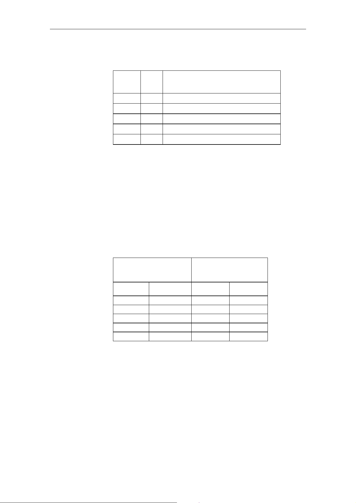
Channel
axis
index
1.
Channel
Machine axis number
0 1 AXCONF_MACHAX_USED [CH1, AX1] = 1
1 2 AXCONF_MACHAX_USED [CH1, AX2] = 2
2 3 AXCONF_MACHAX_USED [CH1, AX3] = 3
3 4 AXCONF_MACHAX_USED [CH1, AX4] = 4
4 5 AXCONF_MACHAX_USED [CH1, AX5] = 5
Assignment of channel axes to machine axes
Switch the control OFF - ON.
Channel %1 machine data %2[%3] contains an axis that is not defined in
the channel
%1 = channel number
%2 = string: MD identifier
%3 = index: MD array index
Only axes that have been activated in the channel via MD 20070
AXCONF_MACHAX_USED [kx]=m may be declared by means of MD 20050
AXCONF_GEOAX_ASSIGN_TAB [gx]=k.
gx ... geometry axis index: k ... channel axis number
kx ... channel axis index m ... machine axis No.
MD 20050
AXCONF_GEOAX_ASSIGN_TAB
(contains channel axis No. k) (contains machine axis No. m)
MD 20070
AXCONF_MACHAX_USED
Reactions
Geometry axis
index
1. Channel Channel axis
index
1. Channel
0 1 0 1
1 2 1 2
2 3 2 3
3 4
4 5
Assignment of geometry axes to channel axes
Alarm display.
Interface signals are set.
NC not ready.
NC Start disable.
NC Stop on alarm.
6FC5398-2CP10-0BA0 © Siemens AG, 2004. All rights reserved
1-12 SINUMERIK 802D sl (DG)
Page 13

12.04 1 Alarms
Remedy
Program continuation
4004
Explanation
Reactions
Remedy
Program continuation
Please inform the authorized personnel/service department.
Check and correct MD 20050 AXCONF_GEOAX_ASSIGN TAB and
MD 20070 AXCONF_MACHAX_USED.
MD array MD 20070 AXCONF_MACHAX_USED, in which the channel-specific
machine axis number to be controlled by this channel is entered. These
resulting ”Channel axes” are given a name by MD 20080
AXCONF_CHANAX_NAME_TAB and assigned to a geometry axis by MD
20050 AXCONF_GEOAX_ASSIGN_TAB by entering the corresponding
channel axis in this MD array for each geometry axis.
Switch the control OFF - ON.
Channel %1 machine data %2 axis %3 defined repeatedly as geometry
axis
%1 = channel number
%2 = string: MD identifier
%3 = axis index
An axis may only be defined once as a geometry axis.
Alarm display.
Interface signals are set.
NC not ready.
NC Start disable.
NC Stop on alarm.
Correct MD 20050 AXCONF_GEOAX_ASSIGN_TAB
Switch the control OFF - ON.
4010
Explanation
Reactions
Remedy
Program continuation
Machine data %1[%2] contains invalid identifier
%1 = string: MD identifier
%2 = index: MD array index
When defining names for machine axes, one of the following syntax rules for
the identifier to be entered has been violated:
1. The identifier must be an NC address letter (A, B, C, I, J, K, U, V, W, X, Y,
Z), possibly with a numerical extension.
2. The identifier must begin with 2 arbitrary capital letters but not with $
(reserved).
3. The identifier must not be a vocabulary word of the NC language (e.g.
SPOS).
Alarm display.
Interface signals are set.
NC not ready.
NC Start disable.
NC Stop on alarm.
Please inform the authorized personnel/service department.
Enter the identifier for user-defined names with correct syntax in the displayed
MD.
Machine axes: MD 10000 AXCONF_MACHAX_NAME_TAB
Switch the control OFF - ON.
© Siemens AG, 2004. All rights reserved 6FC5398-2CP10-0BA0
SINUMERIK 802D sl (DG) 1-13
Page 14

1 Alarms 12.04
4011
Explanation
Reactions
Remedy
Program continuation
Channel %1 Machine data %2[%3] contains invalid identifier
%1 = channel number
%2 = string: MD identifier
%3 = index: MD array index
When defining names in the channel-specific tables for geometry axes and
channel axes, one of the following syntax rules for the identifier to be entered
has been violated:
1. The identifier must be an NC address letter (A, B, C, I, J, K, U, V, W, X, Y,
Z), possibly with a numerical extension.
2. The identifier must begin with 2 arbitrary capital letters but not with $
(reserved for system variable).
3. The identifier must not be a vocabulary word of the NC language (e.g.
SPOS).
Alarm display.
Interface signals are set.
NC not ready.
NC Start disable.
NC Stop on alarm.
Please inform the authorized personnel/service department.
Enter the identifier for user-defined names with correct syntax in the displayed
MD
Geometry axes: MD 20060 AXCONF_GEOAX_ASSIGN_TAB
Channel axes: MD 10000 AXCONF_MACHAX_NAME_TAB
Switch the control OFF - ON.
4012
Explanation
Reactions
Remedy
Program continuation
4020
Explanation
Reactions
Machine data %1[%2] contains invalid identifier
%1 = string: MD identifier
%2 = index: MD array
The selected identifier is invalid. The following are valid identifiers:
• AX1 - AXn: Machine axis identifiers
Alarm display.
Interface signals are set.
NC not ready.
Channel not ready.
NC start inhibit in this channel.
NC stop for alarm.
Use the correct identifier.
Switch the control OFF - ON.
Identifier %1 used several times in machine data %2
%1 = string: Identifier
%2 = string: MD identifier
To determine the name in the channel-specific tables (arrays) for machine
axes an identifier already existing in the control has been used.
Alarm display.
Interface signals are set.
NC not ready.
NC Start disable.
NC Stop on alarm.
6FC5398-2CP10-0BA0 © Siemens AG, 2004. All rights reserved
1-14 SINUMERIK 802D sl (DG)
Page 15

12.04 1 Alarms
Remedy
Program continuation
4021
Explanation
Reactions
Remedy
Program continuation
4030
Explanation
Reactions
Remedy
Program continuation
Please inform the authorized personnel/service department.
Select for the identifier to be entered a character string that is not yet used in
the system (max. 32 characters).
Cancel alarm in all channels of this mode group by pressing RESET.
Channel %1 identifier %2 used several times in machine data %3
%1 = channel number
%2 = string: identifier
%3 = string: MD identifier
To determine the name in the channel-specific tables for geometry axes and
channel axes an identifier already existing in the control has been used.
Alarm display.
Interface signals are set.
NC not ready.
NC Start disable.
NC Stop on alarm.
Please inform the authorized personnel/service department.
Select for the identifier to be entered a character string that is not yet used in
the system (max. 32 characters).
Switch the control OFF - ON.
Channel %1 axis identifier missing in machine data %2[%3]
%1 = channel number
%2 = string: MD identifier
%3 = index: MD array index
An axis identifier is expected for the displayed MD in accordance
with the axis configuration in the AXCONF_MACHAX_USED
and MD 20050 AXCONF_GEOAX_ASSIGN_TAB.
Alarm display.
Interface signals are set.
NC not ready.
NC Start disable.
NC Stop on alarm.
Please inform the authorized personnel/service department.
Check axis configuration and enter the missing identifier into the MD or, should
the axis not exist, specify for this channel axis the machine axis 0 in MD 20070
AXCONF_MACHAX_USED. If this concerns a geometry axis that is not to be
used (this applies only for 2-axis machining, e.g. on lathes), then channel axis 0
must be entered additionally in MD 20050 AXCONF_GEOAX_ASSIGN_TAB
for the relevant geometry axis.
Switch the control OFF - ON.
© Siemens AG, 2004. All rights reserved 6FC5398-2CP10-0BA0
SINUMERIK 802D sl (DG) 1-15
Page 16

1 Alarms 12.04
4032
Explanation
Reactions
Remedy
Program continuation
4040
Explanation
Reactions
Remedy
Program continuation
Channel %1 wrong identifier for facing axis in %2
%1 = channel number
%2 = string: MD identifier
According to the axis configuration in MD 20150 GCODE_RESET_VALUES or
MD 20100 DIAMETER_AX_DEF, a facing axis identifier is expected at the
specified location.
Alarm display
Interface signals are set
NC Stop on alarm
NC not ready
NC start disable
Please inform the authorized personnel/service department.
Add the correct identifier.
Switch the control OFF - ON.
Channel %1 axis identifier %2 not consistent with machine data %3
%1 = channel number
%2 = string: axis identifier
%3 = string: MD identifier
The use of the specified axis identifier in the displayed MD is not consistent the
channel's axis configuration stated in the MD 20070
AXCONF_MACHAX_USED and MD 20050 AXCONF_GEOAX_ASSIGN_TAB.
Alarm display.
Interface signals are set.
NC not ready.
NC Start disable.
NC Stop on alarm.
Please inform the authorized personnel/service department.
Check and correct the identifier used in the MD 10000 AXCONF_
MACHAX_NAME_TAB, MD 20080 AXCONF_CHANAX_NAME_TAB and/or
MD 20050 AXCONF_GEOAX_NAME_TAB.
Switch the control OFF - ON.
4045
Explanation
Reactions
Remedy
Program continuation
6FC5398-2CP10-0BA0 © Siemens AG, 2004. All rights reserved
1-16 SINUMERIK 802D sl (DG)
Channel %1 conflict between machine data %2 and machine data %3
%1 = channel number
%2 = string: MD identifier
%3 = string: MD identifier
Using the specified machine data %1 leads to a conflict with machine data %2.
NC not ready.
NC start inhibit in this channel.
Interface signals are set.
Alarm display.
NC Stop on alarm
Correct the specified machine data.
Switch the control OFF - ON.
Page 17

12.04 1 Alarms
4050
Explanation
Reactions
Remedy
Program continuation
NC code identifier %1 cannot be reconfigured to %2
%1 = String: Old identifier
%2 = String: New identifier
Renaming of an NC code was not possible for one of the following reasons:
• The old identifier does not exist
• The new identifier is within another type range.
NC codes/vocabulary words can be reconfigured per machine data as long as
you stay within the type range.
Type 1: "true" G codes: G02, G17, G33, G64, ...
Type 2: named G codes: CIP, TRANS, ...
Type 3: addresses which can be set: X, Y, I, J, K, MEAS
Alarm display.
Interface signals are set.
NC not ready.
NC Start disable.
NC Stop on alarm.
Please inform the authorized personnel/service department.
Correct MD 10712 NC_USER_CODE_CONF_NAME_TAB (protection level 1).
The list must be built up as follows:
Even address: Identifier to be modified
Following odd address: New identifier
E.g.: NC_USER_CODE_CONF_NAME_TAB[10] = "ROT"
NC_USER_CODE_CONF_NAME_TAB [11] = " "
deletes the function ROT from the control
Switch the control OFF - ON.
4060
Explanation
Reaction
Remedy
Program continuation
4062
Explanation
Reaction
Remedy
Program continuation
Standard machine data loaded
Startup with defaults values by means of:
• Operation (e.g. commissioning switch)
• MD 11200 INIT_MD
• Loss of remanent data
• Startup operation with backup data, without saving current data
Alarm display
After automatically loading the standard MDs, the individual MDs must be
entered/loaded in the relevant system.
Clear the alarm with the cancel key. Load specific machine data again.
Backup data loaded
The user data saved in the flash memory are loaded to the SRAM.
Alarm display
Load specific machine data again.
Clear the alarm with the RESET key.
© Siemens AG, 2004. All rights reserved 6FC5398-2CP10-0BA0
SINUMERIK 802D sl (DG) 1-17
Page 18

1 Alarms 12.04
4065
Explanation
Reactions
Remedy
Program continuation
4070
Explanation
Reaction
Remedy
Program continuation
Buffered memory was restored from backup copy (potential loss of data!)
A possible inconsistency was detected in the buffered memory during power-up.
The buffered memory was initialized with the last backup copy. Changes in the
buffered memory, which have been made since the last backup copy update,
have been lost. The reason for this procedure is that the backup time is
exceeded. Make sure that the required operating time of the control
corresponds to the specifications in your Installation & Start-Up Guide.
The current backup copy of the buffered memory has been created by the last
internal data backup carried out via the "Save data" softkey on the HMI.
Alarm display
Interface signals are set
NC Start disable
Restart the control.
Scaling machine data modified
The control uses internal physical units (mm, degrees, s, for paths, velocities,
acceleration, etc.). During programming or data storage, some of these values
are input and output using different units (rev./min, m/s2, etc.).
The conversion is carried out using scaling factors which can be entered
(system-specific MD array 10230 SCALING_FACTORS USER_DEF[n] (n ...
Index number 0 - 10) when the relevant masking bit is set to "1".
If the masking bit is set to "0" then scaling takes place with the internal standard
factors.
The following machine data influence the scaling of other MDs:
MD 10220 SCALING_USER_DEF_MASK
MD 10230 SCALING_FACTORS_USER_DEF
MD 10240 SCALING_SYSTEM_IS_METRIC
MD 10250 SCALING_VALUE_INCH
MD 30300 IS_ROT_AX
After these data are changed, the NC must be restarted. Only then will the input
of dependent data be performed correctly.
Alarm display.
Please inform the authorized personnel/service department.
If the alarm has been displayed after downloading an MD file which is
consistent within itself, then the download operation must be repeated with a
new NC power-up. (The file contains scaling-dependent machine data in front of
the scaling factors).
Clear the alarm with the cancel key. No further operator action required.
6FC5398-2CP10-0BA0 © Siemens AG, 2004. All rights reserved
1-18 SINUMERIK 802D sl (DG)
Page 19

12.04 1 Alarms
4071
Explanation
Reaction
Remedy
Program continuation
4075
Explanation
Reaction
Remedy
Program continuation
Check the position of the absolute encoder
A machine data that affects the position of an absolute encoder has been
changed. Please check the position values.
Alarm display.
Please inform the authorized personnel/service department.
Clear the alarm with the Cancel key or with NC START.
Machine data %1 (and maybe others) not altered due to missing access
authorization %2
%1 = string: MD identifier
%2 = write-protection level of MD
On executing a TOA file, an attempt has been made to write an item of data
with a higher protection level than the access authorization currently set in the
control.
The item of data affected was not written.
This alarm is set only when access violation is detected for the first time.
Alarm display.
Set the required access level per password entry or delete the machine data
concerned from the MD file.
Clear the alarm with the cancel key. No further operator action required.
4076
Explanation
Reaction
Remedy
Program continuation
%1 Machine data could not be altered with access authorization %2
%1 = number of MD
%2 = access authorization set
On executing a TOA file, an attempt has been made to write data with a higher
protection level than the access authorization currently set in the control.
The data affected was not written.
This alarm is issued when acknowledging Alarm 4075. It can be cleared only
with Power On.
Alarm display.
Set the required access level by means of keyswitch or password entry or
delete the machine data concerned from the MD file program.
Switch the control OFF - ON.
© Siemens AG, 2004. All rights reserved 6FC5398-2CP10-0BA0
SINUMERIK 802D sl (DG) 1-19
Page 20

1 Alarms 12.04
4077
Explanation
Reaction
Remedy
Program continuation
New value %1 of MD %2 not set. Requested %3 bytes too much %4
memory.
%1 = New value of machine data
%2 = Machine data number
%3 = Number of bytes to many requested
%4 = Type of memory
An attempt was made to enter a new value in the specified memory
configuration machine data.
The change is not made, since it would result in the user memory being
deleted. This is because the memory requested exceeded the available
capacity.
The third parameter specifies the number of bytes by which the maximum user
memory was exceeded.
The fourth parameter specifies the type of memory whose limit was exceeded.
"D" stands for dynamic or non-buffered user memory (this is where the LUD
variables are stored and the interpolation buffer size is entered, for example).
The capacity of this memory type is defined by the current memory expansion
and the value in MD18210 MM_USER_MEM_DYNAMIC.
"S" stands for static or buffered user memory (typically the part programs but
also compensation data, R parameters and tool data). The capacity of this
memory type is defined by the current memory expansion and the value in
MD 18230 MM_USER_MEM_BUFFERED.
Alarm display.
If the modification was unintentional, simply continue.
The alarm has no negative effects.
The remedy depends on the access authorization and the current memory
expansion of the NC.
The intended change is mot possible -> try again with a lower value. Observe
how the value of the byte number changes.
Buy more memory? This option depends on the particular model used.
The NC user memory setting may be smaller than possible. The MDs (see
above) can be altered using the relevant access authorization.
Clear the alarm with the cancel key. No further operator action required.
4090
Explanation
Reactions
Remedy
Program continuation
6FC5398-2CP10-0BA0 © Siemens AG, 2004. All rights reserved
1-20 SINUMERIK 802D sl (DG)
Too many faults during power up
More than <n> errors occurred during control power-up.
Alarm display.
NC Start disable.
Set the machine data correctly.
Page 21

12.04 1 Alarms
4110
Explanation
Reaction
Remedy
Program continuation
4111
Explanation
Reaction
Remedy
Program continuation
Factor IPO cycle increased to %1 ms
%1 = String (new IPO cycle)
The IPO cycle divisor was set to a value which was not an integral multiple of
the position control cycle divisor.
The divisor (MD 10070 IPO_SYSCLOCK_TIME_RATIO) was increased.
IPO_SYSCLOCK_TIME_RATIO has been modified on systems with
PROFIBUS DP because of the modified DP cycle in the SDB (MD 10050
SYSCLOCK_CYCLE_TIME).
Alarm display.
Machine data 10070 IPO_SYSCLOCK_TIME_RATIO has been modified.
Clear the alarm with the RESET key. Restart part program.
Increase PLC cycle to %1 ms
The PLC cycle divisor was set to a value which was not an integral multiple of
the IPO cycle divisor.
The divisor (MD 10 074 PLC_IPO_TIME_RATIO) has been increased.
Alarm display.
Adapt machine data.
Switch the control OFF - ON.
4112
Explanation
Reaction
Remedy
Program continuation
4113
Explanation
Reaction
Remedy
Program continuation
Servo cycle changed to %1 ms
%1 = String (new servo cycle)
MD 10060 POSCTRL_SYSCLOCK_TIME_RATIO has been modified because
of the modified DP cycle in SDB1000 (10050 SYSCLOCK_CYCLE_TIME).
Alarm display.
Machine data 10060 POSCTRL_SYSCLOCK_TIME_RATIO RATIO has been
modified.
Clear the alarm with the RESET key. Restart part program.
Sysclock cycle changed to %1 ms
%1 = String (new PLC cycle)
MD 10050 SYSCLOCK_CYCLE_TIME has been modified because of the
modified DP cycle in the SDB.
Alarm display.
Machine data 10050 SYSCLOCK_CYCLE_TIME has been modified.
Clear the alarm with the RESET key. Restart part program.
© Siemens AG, 2004. All rights reserved 6FC5398-2CP10-0BA0
SINUMERIK 802D sl (DG) 1-21
Page 22

1 Alarms 12.04
4114
Explanation
Reaction
Remedy
Program continuation
4150
Explanation
Reactions
Remedy
Program continuation
Error in DP cycle of the SDB
%1 = String (new PLC cycle)
The DP cycle in the SDB contains an error and cannot be set.
The default value of MD 10050 SYSCLOCK_CYCLE_TIME is set.
Alarm display.
Correct the SDB.
Switch the control OFF - ON.
Channel %1 invalid M function subprogram call configured
%1 = Channel number
In MD MD 10715 M_NO_FCT_CYCLE, an M function that is occupied by the
system has been specified for the configuration of the subprogram call and
cannot be replaced by a subprogram call (M0 to M5, M17, M19, M30, M40 to
M45, M70). When external language is active, M96 to M99 are also blocked
Alarm display.
NC Start disable.
Interface signals are set.
NC not ready.
NC Stop on alarm.
Configure an M function which is not used by the system (M0 to M5, M17, M19,
M30, M40 to M45 and M70) in MD 10715 M_NO_FCT_CYCLE.
4152
Explanation
Reactions
Remedy
Program continuation
Illegal configuration of the "Block display with absolute values" function
The "Block display with absolute values" function has been illegally
parameterized:
- An illegal block length has been set with MD 28400 MM_ABSBLOCK:
While ramping up, the machine data will be checked for the following value
range:
0, 1, 128 to 512
- An invalid display range has been set with MD 28402
MM_ABSBLOCK_BUFFER_CONF[]. While ramping up, the machine data will
be checked for the following upper and lower limits:
0 <= $MC_MM_ABSBLOCK_BUFFER_CONF[0] <= 8
0 <= $MC_MM_ABSBLOCK_BUFFER_CONF[1] <= (MD 28060
MM_IPO_BUFFER_SIZE + MD 28070 MM_NUM_BLOCKS_IN_PREP).
Alarm 4152 is issued if the limits are violated.
Alarm display.
Interface signals are set.
Channel not ready.
NC Stop on alarm.
NC Start disable.
Configure block length/display range within the permissible limits.
Switch the control OFF - ON.
6FC5398-2CP10-0BA0 © Siemens AG, 2004. All rights reserved
1-22 SINUMERIK 802D sl (DG)
Page 23

12.04 1 Alarms
4160
Explanation
Reactions
Remedy
Program continuation
4181
Explanation
Reactions
Remedy
Program continuation
Channel %1 invalid M function number for spindle switchover configured
%1=Channel number
An M function was specified in MD 20094 SPIND_RIGID_TAPPING_M_NR to
configure the M function number for spindle switchover to axis mode. The M
function number is assigned by the system and cannot be used for the
switchover (M1 to M5,M17, M30, M40 to M45).
Alarm display.
Interface signals are set.
NC not ready.
NC Start disable.
NC Stop on alarm.
Configure an M function which is not used by the system (M1 to M5, M17, M30,
M40 to M45) in MD 20094 SPIND_RIGID_TAPPING_M_NR.
Channel %1 invalid assignment of an M auxiliary function number
%1 = channel number
In machine data 22254 AUXFU_ASSOC_M0_VALUE or 22256
AUXFU_ASSOC_M1_VALUE, a number has been specified for the
configuration of a new predefined M function which is occupied by the system,
and cannot be used for an assignment. (M0 to M5, M17, M30, M40 to M45).
Alarm display.
Interface signals are set.
Channel not ready.
NC Start disable in this channel.
NC Stop on alarm.
Configure an M function in machine data 22254 AUXFU_ASSOC_M0_VALUE
or 22256 AUXFU_ASSOC_M1_VALUE which is not occupied by the system
(M1 to M5, M17, M30, M40 to M45).
Switch the control OFF - ON.
4182
Explanation
Reactions
Channel %1 invalid M auxiliary function number in %2%3, MD reset
%1 = channel number
%2 = machine data identifier
%3 = if necessary, MD index
In the specified machine data, a number has been specified for the
configuration of an M function which is occupied by the system, and cannot be
used for an assignment.
(M0 to M5, M17, M30, M40 to M45 and also M98, M99 with applied ISO
dialect).
The value set by the user has been reset to the default value by the system.
Alarm display.
Interface signals are set.
Channel not ready.
NC Start disable in this channel.
NC Stop on alarm.
© Siemens AG, 2004. All rights reserved 6FC5398-2CP10-0BA0
SINUMERIK 802D sl (DG) 1-23
Page 24

1 Alarms 12.04
Remedy
Program continuation
4183
Explanation
Reactions
Remedy
Program continuation
Configure an M function in the specified machine data which is not occupied by
the system (M0 to M5, M17, M30, M40 to M45 and also M98, M99 with applied
ISO dialect).
Clear the alarm with the RESET key. Restart part program.
Channel %1 M auxiliary function number %2 used several times
(%3 and %4)
%1 = channel number.
%2 = M auxiliary function number.
%3 = machine data identifier.
%4 = machine data identifier.
In the specified machine data, a number has been used several times for the
configuration of an M function.
Alarm display.
Interface signals are set.
Channel not ready.
NC Start disable in this channel.
NC Stop on alarm.
Check the specified machine data and create a unique assignment of M
auxiliary function numbers.
Switch the control OFF - ON.
4184
Explanation
Reactions
Remedy
Program continuation
4185
Explanation
Channel %1 illegally predefined auxiliary function in %2%3, MD reset
%1 = channel number
%2 = machine data identifier
%3 = if necessary, MD index
In the specified machine data, a predefined auxiliary function has been illegally
configured.
The value set by the user has been reset to the default value by the system.
Channel not ready.
NC start inhibit in this channel.
Interface signals are set.
Alarm display.
NC Stop on alarm.
Configure a valid value in the specified machine data.
Clear the alarm with the RESET key. Restart part program.
Channel %1 illegal auxiliary function configured %2 %3 %4
%1 = channel number.
%2 = type of auxiliary function.
%3 = extension.
%4 = auxiliary function value.
An auxiliary function has been illegally configured.
Predefined auxiliary functions cannot be reconfigured by user-defined auxiliary
functions.
6FC5398-2CP10-0BA0 © Siemens AG, 2004. All rights reserved
1-24 SINUMERIK 802D sl (DG)
Page 25

12.04 1 Alarms
Reactions
Remedy
Program continuation
4200
Explanation
Reactions
Remedy
Program continuation
Channel not ready
NC start inhibit in this channel
Interface signals are set
Alarm display
NC stop for alarm
Reconfigure the auxiliary function.
Clear the alarm with the RESET key. Restart part program.
Channel %1 geometry axis %2 must not be declared a rotary axis
%1 = channel number
%2 = axis name
The geometry axes represent a Cartesian coordinate system and therefore the
declaration of a geometry axis as rotary axis leads to a definition conflict.
NC not ready.
NC Stop on alarm.
Alarm display.
Interface signals are set.
Please inform the authorized personnel/service department.
Remove rotary axis declaration for this machine axis.
For this purpose, the geometry axis index for the displayed geometry axis must
be determined by means of the machine data array 20060
AXCONF_GEOAX_NAME_TAB. The channel axis number is stored with the
same index in the MD array 20050 AXCONF_GEOAX_ASSIGN_TAB. The
channel axis number minus 1 provides the channel axis index under which the
machine axis number is found in the MD array 20070
AXCONF_MACHAX_USED.
Switch the control OFF - ON.
4210
Explanation
Reactions
Remedy
Program continuation
Channel %1 spindle %2 declaration as rotary axis missing
%1 = channel number
%2 = axis name, spindle number
If a machine axis is to be operated as a spindle, this machine axis must be
declared as a rotary axis.
NC not ready.
NC Stop on alarm.
Alarm display.
Interface signals are set.
Please inform the authorized personnel/service department.
Set rotary axis declaration for this machine axis in the axis-specific MD 30300
IS_ROT_AX.
Switch the control OFF - ON.
© Siemens AG, 2004. All rights reserved 6FC5398-2CP10-0BA0
SINUMERIK 802D sl (DG) 1-25
Page 26

1 Alarms 12.04
4215
Explanation
Reactions
Remedy
Program continuation
4220
Explanation
Reactions
Remedy
Program continuation
Channel %1 spindle %2 declaration as modulo axis missing
%1 = channel number
%2 = axis name, spindle number
The spindle functionality requires a modulo axis (positions in [deg]).
NC not ready.
NC Stop on alarm.
Alarm display.
Interface signals are set.
Please inform the authorized personnel/service department.
Set MD 30310 ROT_IS_MODULO.
Switch the control OFF - ON.
Channel %1 spindle %2 declared repeatedly
%1 = channel number
%2 = axis name, spindle number
The spindle number exists more than once in the channel.
Alarm display.
Interface signals are set.
NC not ready.
NC Start disable.
NC Stop on alarm.
Please inform the authorized personnel/service department.
The spindle number is stored in the axis-specific MD array 35000
SPIND_ASSIGN_TO_MACHAX. The channel to which this machine axis/
spindle is assigned is listed in the machine axis index. (The machine axis
number is given in the MD array 20070 AXCONF_MACHAX_USED).
Switch the control OFF - ON.
4225
Explanation
Reactions
Remedy
Program continuation
Channel %1 axis %2 declaration as rotary axis missing
%1 = channel number
%2 = axis name, axis number
The modulo functionality requires a rotary axis (positions in [deg]).
NC not ready.
NC Stop on alarm.
Alarm display.
Interface signals are set.
Please inform the authorized personnel/service department.
Set MD 30300 IS_ROT_AX.
Switch the control OFF - ON.
6FC5398-2CP10-0BA0 © Siemens AG, 2004. All rights reserved
1-26 SINUMERIK 802D sl (DG)
Page 27

12.04 1 Alarms
4230
Explanation
Reaction
Remedy
Program continuation
4240
Explanation
Reactions
Remedy
Program continuation
Channel %1 data alteration from external not possible in current channel
state
%1 = channel number
It is not allowed to enter this data while the part program is being executed (e.g.
setting data for spindle speed limitation or for dry run feedrate).
Alarm display.
The data to be entered must be altered before starting the part program.
Clear the alarm with the cancel key. No further operator action required.
Runtime overflow for IPO cycle or position controller cycle, IP %1
%1 = Program position
The settings for the interpolation and position control cycle were modified
before the last power-up such that too little computing time is now available for
the requisite cyclic task.
The alarm occurs immediately after power-up if too little runtime is available
even when the axes are stationary and the NC program has not started.
However, task overflow can occur only when computation-intensive NC
functions are called during program execution.
NC not ready.
NC Start disable.
NC Stop on alarm.
The NC switches to follow-on mode.
Alarm display.
Interface signals are set.
Please inform the authorized personnel/service department.
Take greater care when optimizing the clock times NC MD 10050
SYSCLOCK_CYCLE_TIME,
MD 10060 POSCTRL_SYSCLOCK_TIME_RATIO and/or
MD 10070 IPO_SYSCLOCK_TIME_RATIO.
The test should be performed with an NC program that represents the highest
load on the control. For safety, a margin of 15 to 25% should be added to the
times determined in this way.
Switch the control OFF - ON.
4260
Explanation
Reactions
Remedy
Program continuation
© Siemens AG, 2004. All rights reserved 6FC5398-2CP10-0BA0
SINUMERIK 802D sl (DG) 1-27
Machine data %1 illegal
%1 = String: MD identifier
The selected cam pair was not activated by MD 10450
SW_CAM_ASSIGN_TAB or more than one cam pair has been selected.
Alarm display.
Interface signals are set.
NC start inhibit in this channel.
NC stop on alarm.
Activate the cam pair or select only one cam pair.
Switch the control OFF - ON.
Page 28

1 Alarms 12.04
4270
Explanation
Reactions
Remedy
Program continuation
Machine data %1 assigns not activated NCK input/output byte %2
%1 = string: MD identifier
%2 = index
The specified machine data assigns a digital input/output byte or an analog
input/output signal the processing of which has not been activated to an NC
function.
Alarm display.
Interface signals are set.
NC not ready.
Channel not ready.
NC start inhibit in this channel.
NC stop on alarm.
Please inform the authorized personnel/service department. Correct machine
data.
Active required inputs/outputs via MD:
• MD 10350 FASTIO_DIG_NUM_INPUTS
• MD 10360 FASTIO_DIG_NUM_OUTPUTS
• MD 10300 FASTIO_ANA_NUM_INPUTS
• MD 10310 FASTIO_ANA_NUM_OUTPUTS
Activation of fast inputs/outputs does not require the corresponding hardware
configuration to be available at the control. All functions using fast
inputs/outputs can also be made use of by the PLC specification/modification
defined in the VDI interface, if the response time requirements are reduced
accordingly.
Activated inputs/outputs increase the computation time requirement of the
interpolation cycle because the PLC manipulation signals are handled cyclically.
Note: Deactivate any inputs/outputs not in use.
Switch the control OFF - ON.
4275
Explanation
Reactions
Remedy
Program continuation
Machine data %1 and %2 both assign the same NCK output byte no. %3
several times
%1 = string: MD identifier
%2 = string: MD identifier
%3 = No. of output
The specified machine data assign two NC functions to the same digital/analog
output.
Alarm display.
Interface signals are set.
NC not ready.
Channel not ready.
NC Start disable in this channel.
NC Stop on alarm.
Please inform the authorized personnel/service department. Correct machine
data.
Switch the control OFF - ON.
6FC5398-2CP10-0BA0 © Siemens AG, 2004. All rights reserved
1-28 SINUMERIK 802D sl (DG)
Page 29

12.04 1 Alarms
4300
Explanation
Reactions
Remedy
Program continuation
4310
Explanation
Reactions
Remedy
Program continuation
Declaration in MD %1 is not allowed for geometry axis/spindle %2
%1 = string: MD identifier
%2 = axis name, spindle number
Geometry axes and spindles cannot be operated as concurrent positioning
axes.
NC not ready.
NC stop on alarm.
NC start inhibit in this channel.
Alarm display.
Interface signals are set.
Please inform the authorized personnel/service department. Reset MD 30450
IS_CONCURRENT_POS_AX for the axis concerned.
Switch the control OFF - ON.
Declaration in MD %1 index %2 is not allowed
%1 = string: MD identifier
%2 = index in MD array
The MD values must be written in the array in ascending order.
NC not ready.
NC Stop on alarm.
NC start inhibit.
Alarm display.
Interface signals are set.
Correct the MD
Clear the alarm with the RESET key. Restart part program.
4320
Explanation
Reactions
Remedy
Program continuation
Axis %1 function %2 %3 and %4 not allowed
%1 = string: Axis identifier
%2 = string: MD identifier
%3 = string: Bit
%4 = string: MD identifier
The functions declared by the machine data specified cannot be activated at the
same time for one axis.
Channel not ready.
NC start inhibit in this channel.
Interface signals are set.
Alarm display.
NC Stop on alarm.
Deactivate one of the functions.
Switch the control OFF - ON.
© Siemens AG, 2004. All rights reserved 6FC5398-2CP10-0BA0
SINUMERIK 802D sl (DG) 1-29
Page 30

1 Alarms 12.04
4340
Explanation
Reactions
Remedy
Program continuation
4343
Explanation
Reactions
Remedy
Program continuation
Channel %1 invalid transformation type in transformation no. %2
%1 = channel number
%2 = transformation number
An invalid, i.e. undefined, number was entered in one of the machine data
24100 TRAFO_TYPE_1.
This alarm occurs only if a certain type of transformation is not possible in the
specified control type.
Alarm display
Interface signals are set
NC Stop on alarm
Channel not ready
NC start disable
Valid transformation type entered
Switch the control OFF - ON.
Channel %1 attempt made to change the machine data of an active
transformation
%1 = channel number
An attempt was made to change the machine data of an active transformation
in or to activate the machine data with RESET or NEWCONFIG.
Alarm display.
Interface signals are set.
NC Stop on alarm at end of block.
Interpreter stop.
Set valid machine data
Clear the alarm with the RESET key. Restart part program.
4346
Explanation
Reactions
Remedy
Program continuation
Channel %1 invalid geoaxis assignment in machine data %2[%3]
%1 = channel number
%2 = name of machine data
%2 = transformation number
Machine data TRAFO_GEOAX_ASSIGN_TAB_1/2 contains an invalid entry.
The following causes for the error are possible:
- The entry references a channel axis that does not exist.
- The entry is zero (no axis) but the transformation needs the relevant axis as
a channel axis.
Alarm display.
Interface signals are set.
Correction block with reorganization.
NC Stop on alarm at end of block.
Correct the entry in TRAFO_GEOAX_ASSIGN_TAB_1/2 or
TRAFO_AXES_IN_1/2.
Clear the alarm with the RESET key. Restart part program.
6FC5398-2CP10-0BA0 © Siemens AG, 2004. All rights reserved
1-30 SINUMERIK 802D sl (DG)
Page 31

12.04 1 Alarms
4347
Explanation
Reactions
Remedy
Program continuation
4350
Explanation
Reactions
Remedy
Program continuation
Channel %1 invalid channel axis assignment in machine data %2[%3]
%1 = channel number
%2 = name of the machine data
%3 = transformation number
Machine data TRAFO_AXIS_IN_1/2 contains an invalid entry.
The following causes for the error are possible:
- The entry references a channel axis which does not exist.
- The entry is zero (no axis) but the transformation needs the relevant axis as a
channel axis.
Alarm display.
Interface signals are set.
Correction block with reorganization.
NC Stop on alarm at end of block.
Correct the entry in TRAFO_AXES_IN_1/2.
Clear the alarm with the RESET key. Restart part program.
Channel %1 axis identifier %2 machine data %3 not consistent with
machine data %4
%1 = channel number
%2 = string: Axis identifier
%3 = string: MD identifier
%4 = string: MD identifier
MD 32410 JOG_AND_POS_JERK_ENABLE (jerk limitation) and MD 35240
ACCEL_TYPE_DRIVE (acceleration reduction) have been defined as the initial
setting for an axis.
However, the two functions cannot be activated at the same time for one axis.
Alarm display.
Interface signals are set.
Channel not ready.
NC start inhibit in this channel.
NC stop on alarm.
Please inform the authorized personnel/service department. Resetting of 32410
JOG_AND_POS_JERK_ENABLE or MD 35240 ACCEL_TYPE_DRIVE.
Switch the control OFF - ON.
4400
Explanation
Reaction
Remedy
Program continuation
© Siemens AG, 2004. All rights reserved 6FC5398-2CP10-0BA0
SINUMERIK 802D sl (DG) 1-31
MD alteration will cause reorganization of buffered memory (loss of data!)
An MD has been altered that configures the buffered memory. If the NC powers
up with the altered data, this will lead to reorganization of the buffered memory
and thus to the loss of all buffered user data (part programs, tool data, GUD,
leadscrew error compensation, ...).
Alarm display.
If the control includes user data that has not yet been saved, then a data
backup must be performed before the next NC power-up. By manually resetting
the altered MD to the value it had before the last power-up, reorganization of
the memory can be avoided.
Clear the alarm with the cancel key. No further operator action required.
Page 32

1 Alarms 12.04
4402
Explanation
Reaction
Remedy
Program continuation
4502
Explanation
Reaction
Program continuation
%1 causes the machine data to be reset
%1 = machine data
If this machine data is set, the current values of the machine data are
overwritten with the pre-set values on next power up. Under certain
circumstances, this can result in loss of data (also in the backed-up memory).
Alarm display.
Please inform the authorized personnel/service department. If the control
includes user data that has not yet been saved, then a data backup must be
performed before the next NCK power-up. By manually resetting the altered MD
to the value it had before the last power-up, reorganization of the memory can
be avoided.
Clear the alarm with the cancel key. No further operator action required.
Channel %1 Anachronism: %2(%3) -> %4
%1 = channel number
%2 = string: MD identifier
%3 = string: MD identifier
%4 = string: MD identifier
Previously, in MD 20110 RESET_MODE_MASK Bit4 and Bit5, the reset
behavior of the 6th or 8th G group was determined. This setting is now made in
MD 20152 GCODE_RESET_MODE.
In order to ensure compatible handling of "old" data backups, the "old" values
are taken from MD 20110 RESET_MODE_MASK and entered in MD 20152
GCODE_RESET_MODE.
Alarm display.
Clear the alarm with the cancel key. No further operator action required.
5000
Explanation
Reaction
Remedy
Program continuation
Unable to execute communication request
The communication request (data exchange between NC and HMI,
for example: load an NC part program) cannot be executed due lack of
memory. Cause: too many parallel communication requests
Alarm display.
No remedy possible – the operation that produced to alarm must be repeated.
Clear the alarm display with Cancel.
Clear the alarm with the cancel key. No further operator action required.
6FC5398-2CP10-0BA0 © Siemens AG, 2004. All rights reserved
1-32 SINUMERIK 802D sl (DG)
Page 33

12.04 1 Alarms
6000
Explanation
Reactions
Remedy
Program continuation
6010
Explanation
Memory reorganized using standard machine data
The memory management was not able to allocate the NC user memory with
the values in the machine data. Because the total memory is available as
dynamic or static memory for the NC user (e.g. for: the number of tool offsets,
the number of directories and files, etc.) and is therefore not sufficient.
Alarm display.
Interface signals are set.
NC Start disable.
NC Stop on alarm.
Redefine the NC memory structure!
A specific MD for NC user memory allocation cannot be given as the cause of
the alarm. Therefore, the MD initiating the alarm must be determined on the
basis of the default values in the machine data by changing the user-specific
memory structure step by step.
Usually, not just one MD has been chosen too large and therefore it is
advisable to reduce the memory area by a certain proportion in several MDs.
Clear the alarm with the RESET key. Restart part program.
Channel %1 data block %2 not or not completely created, error code %3
%1 = channel number
%2 = string (module name)
%3 = internal error ID
Data management has detected an error in power-up. The specified data block
may not have been created. The error number specifies the type of error. If the
error number >100000, then there is a fatal system error. Otherwise, the user
memory area was made too small. In this case the (user) error codes have the
following meaning:
Error number Explanation
1 No memory space available
2 Maximum number of possible symbols exceeded
3 Index 1 lies outside valid range of values
4 Name in channel already exists
5 Name in NC already exists
If the alarm occurs after cycle programs, macro definitions or definitions for
global user data (GUD) have been introduced, the machine data for the NC
user memory configuration have been incorrectly configured. In all other cases,
modifications to machine data that are already correct produce errors in the
user memory configuration.
The following block names (2nd parameter) are known in the NC (all system
and user data blocks; in general, only problems in the user data blocks can be
remedied by user intervention)
© Siemens AG, 2004. All rights reserved 6FC5398-2CP10-0BA0
SINUMERIK 802D sl (DG) 1-33
Page 34

1 Alarms 12.04
_N_NC_OPT - System-internal: Option data, NC global
_N_NC_SEA - System-internal: Setting data, NC global
_N_NC_TEA - System-internal: Machine data, NC global
_N_NC_CEA - System-internal: 'cross error compensation'
_N_NC_PRO - System-internal: Protection zones, NC global
_N_NC_GD1 - User: 1st GUD block defined by
_SGUD_DEF, NC global
_N_NC_GD2 - User: 2nd GUD block defined by
_N_MGUD_DEF, NC global
_N_NC_GD3 - User: 3rd GUD block defined by
_N_UGUD_DEF, NC global
_N_NC_GD4 - User: 4th GUD block defined by
_N_GUD4_DEF, NC global
_N_NC_GD5 - User: 5th GUD block defined by
_N_GUD5_DEF, NC global
_N_NC_GD6 - User: 6th GUD block defined by
_N_GUD6_DEF, NC global
_N_NC_GD7 - User: 7th GUD block defined by
_N_GUD7_DEF, NC global
_N_NC_GD8 - User: 8th GUD block defined by
_N_GUD8_DEF, NC global
_N_NC_GD9 - User: 9th GUD block defined by
_N_GUD9_DEF, NC global
_N_NC_MAC - User: Macro definitions
_N_NC_FUN - User: Cycle programs
_N_CHc_OPT - System-internal: Option data, channel-specific
_N_CHc_SEA - System-internal: Setting data, channel-specific
_N_CHc_SEA - System-internal: Machine data, channel-specific
_N_CHc_PRO - System-internal: Protection zones, channel-specific
_N_CHc_UFR - System-internal: Frames, channel-specific
_N_CHc_RPA - System-internal: Arithmetic parameters, channel-specific
_N_CHc_GD1 - User: 1st GUD block defined by
_N_SGUD_DEF, channel-specific
_N_CHc_GD2 - User: 2nd GUD block defined by
_N_MGUD_DEF, channel-specific
_N_CHc_GD3 - User: 3rd GUD block defined by
_N_UGUD_DEF, channel-specific
_N_CHc_GD4 - User: 4th GUD block defined by
_N_GUD4_DEF, channel-specific
_N_CHc_GD5 - User: 5th GUD block defined by
_N_GUD5_DEF, channel-specific
_N_CHc_GD6 - User: 6th GUD block defined by
_N_GUD6_DEF, channel-specific
_N_CHc_GD7 - User: 7th GUD block defined by
_N_GUD7_DEF, channel-specific
_N_CHc_GD8 - User: 8th GUD block defined by
_N_GUD8_DEF, channel-specific
_N_CHc_GD9 - User: 9th GUD block defined by
_N_GUD9_DEF, channel-specific
_N_AXa_OPT - System-internal: option data, axial
_N_AXa_SEA - System-internal: setting data, axial
_N_AXa_TEA - System-internal: machine data, axial
_N_AXa_EEC - System-internal: leadscrew error compensation data, axial
_N_AXa_QEC - System-internal: quadrant error compensation data, axial
6FC5398-2CP10-0BA0 © Siemens AG, 2004. All rights reserved
1-34 SINUMERIK 802D sl (DG)
Page 35

12.04 1 Alarms
_N_TOt_TOC - System-internal: tool holder data, TOA-specific
_N_TOt_TOA - System-internal: tool data, TOA-specific
_N_TOt_TMA - System-internal: magazine data, TOA-specific
c = Channel number
a = Machine axis number
t = TOA unit number
Reactions
Remedy
There are further internal system data blocks with identifier.
Alarm display.
Interface signals are set.
NC not ready.
NC Start disable.
NC Stop on alarm.
Correct the machine data or undo the change.
Please inform the authorized personnel/service department.
• There are two determining machine data for cycle programs:
MD 18170 MM_NUM_MAX_FUNC_NAMES = max. number of all
Cycle programs
Error number = 2 shows that this value is too small
MD 18180 MM_NUM_MAX_FUNC_PARAM = max. number of all
parameters defined in the cycle programs
Error number = 2 shows that this value is too small
(If this MD is modified, the memory backup is retained)
Program continuation
6020
Explanation
Reaction
• The following applies to macro definitions:
MD 18160 MM_NUM_USER_MACROS = max. number of all
Macro definitions
Error number = 2 shows that this value is too small
(If this MD is modified, the memory backup is retained)
• The following applies to GUD variables:
MD 18118 MM_NUM_GUD_MODULES = max. number of all
GUD data blocks per area (NC/channel)
(if GD1, GD2, GD3, GD9 are defined, the value must be 9
MD 4 MM_NUM_ GUD_NAMES_NCK = max. number of all
global GUD variables
Error number = 2 shows that this value is too small
MD 18130 MM_NUM_GUD_NAMES_CHAN = max. number of all
Channel-specific GUD variables in the channel
Error number = 2 shows that this value is too small
MD 18150 MM_GUD_VALUES_MEM = max. memory values
all GUD variables together
Error number = 1 shows that this value is too small
Switch the control OFF - ON.
Clear the alarm with the RESET key. Restart part program.
Machine data have been altered - now memory is reorganized
Machine data have been changed that define the NC user memory allocation.
Data management has restructured the memory in accordance with the altered
machine data.
Alarm display.
© Siemens AG, 2004. All rights reserved 6FC5398-2CP10-0BA0
SINUMERIK 802D sl (DG) 1-35
Page 36

1 Alarms 12.04
Remedy
Program continuation
6030
Explanation
Reaction
Remedy
Program continuation
6035
Explanation
Reaction
Remedy
Program continuation
No remedial action is required. Any user data that are required must be input
again.
Clear the alarm with the RESET key. Restart part program.
Limit of user memory has been adapted
Data management checks during power-up the actually available physical user
memory (DRAM, DPRAM and SRAM) with the values in the system-specific
machine data 18210
MM_USER_MEM_DYNAMIC, MD 18220 MM_USER_MEM_DPR and
MD 18230 MM_USERMEM_BUFFERED.
Alarm display.
No remedial action is required. The new maximum permissible value can be
read from the reduced machine data.
Clear the alarm with the RESET key. Restart part program.
Instead of %1 KB the system has only %2 KB of free user memory of type
"%3"
%1 = free memory defined for the control model in KB
%2 = actual maximum amount of free memory in KB
%3 = type of memory, "D" = non-buffered, "S" = buffered
The alarm can only occur after a 'cold start' (=NCK start-up with standard
machine data). The alarm is only a notice. There is no interference with any
NCK functions. It shows that the NCK has less free user memory available than
specified by Siemens for this control variant. The value of the actually available
free user memory can also be taken from the machine data 18050
INFO_FREE_MEM_DYNAMIC, 18060 INFO_FREE_MEMS_STATIC.
Siemens supplies NCK with default settings that, depending on the model, have
certain (free) memory space available for the specific settings of the actual
applications. The original factory setting of NCK systems is thus that the alarm
does not occur with a cold start.
Alarm display.
The cause of this message may be that the NCK is running on hardware that is
not intended for this NCK version (i.e. it has insufficient memory).
If the application runs properly with the remaining free user memory (i.e. can be
started up without any errors), the message can simply be ignored.
Clear the alarm with the RESET key.
6410
Explanation
6FC5398-2CP10-0BA0 © Siemens AG, 2004. All rights reserved
1-36 SINUMERIK 802D sl (DG)
TO unit %1 tool "%2" / duplo no. %3 has reached prewarning limit with
D = %4
%1 = TO unit
%2 = Tool identifier (name)
%3 = Duplo number
%4 = D number
Page 37

12.04 1 Alarms
Tool monitoring:
This message informs that the specified D offset has reached its prewarning
limit for a time- or quantity-monitored tool.
If possible, the D number is displayed; if not, value 0 is assigned to the 4th
parameter.
The actual type of tool monitoring is a tool property (see $TC TP9).
If replacement tools are not being used,
the duplo number specified has no meaning.
The alarm is triggered through the MMC or PLC (=OPI interface). The channel
context is not defined. The TO unit is specified for this reason.
Reactions
Remedy
Program continuation
Alarm display.
Interface signals are set.
For information only. The user must decide what to do.
Clear the alarm with the cancel key. No further operator action required.
6411
Explanation
Reactions
Remedy
Program continuation
Channel %1 tool "%2" / duplo no. %3 has reached prewarning limit with
D = %4
%1 = TO unit
%2 = Tool identifier (name).
%3 = Duplo number
%4 = D number
Tool monitoring:
This message informs that the specified D offset has reached its prewarning
limit for a time- or quantity-monitored tool.
If possible, the D number is displayed; if not, value 0 is assigned to the 4th
parameter.
The actual type of tool monitoring is a tool property (see $TC TP9).
If replacement tools are not being used,
the duplo number specified has no meaning.
The alarm originates during NC program execution.
Alarm display.
Interface signals are set.
For information only. The user must decide what to do.
Clear the alarm with the cancel key. No further operator action required.
© Siemens AG, 2004. All rights reserved 6FC5398-2CP10-0BA0
SINUMERIK 802D sl (DG) 1-37
Page 38

1 Alarms 12.04
6412
Explanation
Reactions
Remedy
Program continuation
6413
Explanation
Reactions
Remedy
Program continuation
TO unit %1 tool "%2" / duplo no. %3 has reached monitoring limit with
D = %4
%1 = TO unit
%2 = Tool identifier (name)
%3 = Duplo number
%4 = D number
Tool monitoring:
This message informs that the specified D offset has reached its monitoring
limit for a time- or quantity-monitored tool.
If possible, the D number is displayed; if not, value 0 is assigned to the 4th
parameter.
The actual type of tool monitoring is a tool property (see $TC TP9).
If replacement tools are not being used, the duplo number specified has no
meaning.
The alarm is triggered through the MMC or PLC (=OPI interface). The channel
context is not defined. The TO unit is specified for this reason.
Alarm display.
Interface signals are set.
For information only. The user must decide what to do.
Clear the alarm with the cancel key. No further operator action required.
Channel %1 tool %2 / duplo no. %3 has reached monitoring limit with
D = %4
%1 = TO unit
%2 = Tool identifier (name)
%3 = Duplo number
%4 = D number
Tool monitoring:
This message informs that the specified D offset has reached its monitoring
limit for a time- or quantity-monitored tool.
If possible, the D number is displayed; if not, value 0 is assigned to the 4th
parameter.
The actual type of tool monitoring is a tool property (see $TC TP9).
If replacement tools are not being used, the duplo number specified has no
meaning.
The alarm originates during NC program execution.
Alarm display.
Interface signals are set.
For information only. The user must decide what to do.
Clear the alarm with the cancel key. No further operator action required.
6FC5398-2CP10-0BA0 © Siemens AG, 2004. All rights reserved
1-38 SINUMERIK 802D sl (DG)
Page 39

12.04 1 Alarms
6430
Explanation
Reactions
Remedy
Program continuation
Workpiece counter: Table of monitored cutting edges overflowed
No further entry of cutting edges possible in the workpiece counter table.
As many cutting edges can be noted for the workpiece counter as are possible
in total in the NCK.
This means that if for each tool each cutting edge is used precisely once for a
workpiece then the limit is reached.
If several workpieces are made on several tool holders/spindles simultaneously,
it is possible to note MD18100 MM_NUM_CUTTING_EDGES_IN_TOA cutting
edges for the workpiece counter for all of the workpieces.
If this alarm occurs, it means that cutting edges used subsequently are no
longer quantity monitored until the table has been emptied again, e.g. by means
of the NC language command SETPIECE or by the relevant job from MMC,
PLC (PI service).
Alarm display.
Interface signals are set.
NC Start disable.
- Have you forgotten to decrement the workpiece counter?
Then program SETPIECE in the part program or in the PLC program, insert
the command correctly.
- If the part program or the PLC is correct, then more memory should be set for
the tool cutting edges via machine data 18100
MM_NUM_CUTTING_EDGES_IN_TOA (only people with proper access
rights can do this!).
Clear the alarm with the cancel key. No further operator action required.
6431
Explanation
Reactions
Remedy
Program continuation
Function not allowed. Tool management/monitoring is not active
Occurs when a data management function is called which is not available
because ToolMan is deactivated. For example, the language commands GETT,
SETPIECE, GETSELT, NEWT, DELT.
Alarm display.
Interface signals are set.
Interpreter stop.
NC Start disable.
• Please inform the authorized personnel/service department.
• Make sure of how the NC is supposed to be configured! Is tool management
or tool monitoring needed but not activated?
• Are you using a part program that is meant for a numerical control with tool
management/tool monitoring? And now this part program is started on the
numerical control without tool management/tool monitoring This does not
work. Either run the part program on the appropriate NC control or edit the
part program.
• Activate tool management/tool monitoring by setting the appropriate
machine data.
See MD 18080 MM_TOOL_MANAGEMENT_MASK,
MD 20310 TOOL_MANAGEMENT_MASK.
• Check that the necessary option is set.
Clear the alarm with the cancel key. No further operator action required.
© Siemens AG, 2004. All rights reserved 6FC5398-2CP10-0BA0
SINUMERIK 802D sl (DG) 1-39
Page 40

1 Alarms 12.04
6432
Explanation
Reactions
Remedy
Program continuation
6500
Explanation
Reaction
Remedy
Program continuation
6510
Explanation
Reaction
Remedy
Program continuation
Function cannot executed. No tool assigned to spindle. Channel %1
%1=Channel number
If an attempt is made to perform an operation in the part program that requires
a tool to be assigned to the tool holder/spindle. This can be the quantity
monitoring function, for example.
Alarm display.
Interface signals are set.
• Select another function, another spindle/spindle, position tool on
spindle/spindle.
Clear the alarm with the Cancel key or with NC START
NC memory full
Too many part programs have been unloaded. The task cannot be executed.
During first start-up the files in the NC file system (part of the NC memory) may
be affected, for example initialization files, NC programs, etc.
Alarm display.
Delete or empty files (e.g. part programs).
Clear the alarm with the cancel key. No further operator action required.
Too many part programs in the NC memory
The number of files in the NC file system (part of the NC memory) has reached
the maximum number possible.
Alarm display.
Delete or empty files (e.g. part programs).
Clear the alarm with the cancel key. No further operator action required.
6530
Explanation
Reaction
Remedy
Program continuation
6540
Explanation
Reaction
Remedy
Program continuation
Too many files in directory
The number of files in one directory of the NC has reached the maximum limit.
Alarm display.
Delete or empty files (e.g. part programs) in the subdirectory affected.
Clear the alarm with the cancel key. No further operator action required.
Too many directories in the NC memory
The number of directories in the NC file system (part of the NC memory) has
reached the maximum number possible.
Alarm display.
Delete or empty directories (e.g. workpiece) that are not required.
Clear the alarm with the cancel key. No further operator action required.
6FC5398-2CP10-0BA0 © Siemens AG, 2004. All rights reserved
1-40 SINUMERIK 802D sl (DG)
Page 41

12.04 1 Alarms
6550
Explanation
Reaction
Remedy
Program continuation
6560
Explanation
Reaction
Remedy
Program continuation
6570
Explanation
Reaction
Remedy
Program continuation
Too many subdirectories
The number of subdirectories in a directory of the NC has reached the
maximum limit.
Alarm display.
Please inform the authorized personnel/service department.
Delete or empty subdirectories in the respective directory, or
Clear the alarm with the cancel key. No further operator action required.
Data format not allowed
Illegal data have been entered in an NC file, e.g. binary data loaded as an
ASCII file.
Alarm display.
Mark the file as binary data (e. g. extension: .BIN).
Clear the alarm with the cancel key. No further operator action required.
NC memory full
The NC card file system of the NC is full. The task cannot be executed. Too
many system files were created in the DRAM.
Alarm display.
Start fewer "Execute from external" processes.
6580
Explanation
Reaction
Remedy
Program continuation
6600
Explanation
Reaction
Remedy
Program continuation
6610
Explanation
Reaction
Remedy
Program continuation
NC memory full
The NC card file system of the NCK is full. The task cannot be executed. To
many files have been loaded
Alarm display.
Delete or empty files (e.g. part programs).
Clear the alarm with the Cancel key or with NC START.
NC card memory is full
The NC card file system of the NC is full. No more data can be stored on the
NC card.
Alarm display.
Delete the data on the PCMCIA card.
Clear the alarm with the cancel key. No further operator action required.
Too many files open on NC card
Too many files accessed simultaneously on the NC card
Alarm display.
Repeat the action later.
Clear the alarm with the cancel key. No further operator action required.
© Siemens AG, 2004. All rights reserved 6FC5398-2CP10-0BA0
SINUMERIK 802D sl (DG) 1-41
Page 42

1 Alarms 12.04
6620
Explanation
Reaction
Remedy
Program continuation
6630
Explanation
Reaction
Remedy
Program continuation
6640
Explanation
Reaction
Remedy
Program continuation
NC card has incorrect format
The NC card cannot be accessed because the format is incorrect.
Alarm display.
Replace the NC card.
Clear the alarm with the cancel key. No further operator action required.
NC card hardware is defective
The NC card cannot be accessed because the card is defective.
Alarm display.
Replace the PCMCIA card.
Clear the alarm with the cancel key. No further operator action required.
NC card is not inserted
The NC card cannot be accessed because the card is not plugged in.
Alarm display.
Plug in the NC card.
Clear the alarm with the cancel key. No further operator action required.
6650
Explanation
Reaction
Remedy
Program continuation
6660
Explanation
Reaction
Remedy
Program continuation
6670
Explanation
Reaction
Remedy
Program continuation
Write protection of NC card is active
The NC card cannot be accessed because the write protection is active.
Alarm display.
Deactivate the write protection.
Clear the alarm with the cancel key. No further operator action required.
'Flash File System' option is not set
The NC card cannot be accessed because the option is not enabled.
Alarm display.
Buy option.
Clear the alarm with the cancel key. No further operator action required.
NC card read active
The alarm is active while the contents of the NC card are being read out. The
FFS cannot be accessed during this period.
Alarm display.
Wait until the read-out procedure is terminated
Alarm display disappears with alarm cause. No further operator action required.
6FC5398-2CP10-0BA0 © Siemens AG, 2004. All rights reserved
1-42 SINUMERIK 802D sl (DG)
Page 43

12.04 1 Alarms
6671
Explanation
Reaction
Remedy
Program continuation
6693
Explanation
Reactions
Remedy
Program continuation
NC card write active
The alarm is active while the contents of the NC card are being written.
The Flash File System cannot be accessed during this period.
If a Power Off occurs while the alarm is present, the contents of the NC will be
destroyed!
Alarm display.
Wait until the write procedure is terminated.
Alarm display disappears with alarm cause. No further operator action required.
File %1 lost
%1 = file name
Due to a power failure, a file change could not be terminated properly. The file
is lost.
Alarm display.
Interface signals are set.
NC not ready.
NC Start disable.
Import the file again.
Power-down the control and power-up again.
6698
Explanation
Reaction
Remedy
Program continuation
7500
Explanation
Unknown NC card (%1/%2). Write not possible
The NC card cannot be accessed because a valid write algorithm is not
available for the flash memory.
Alarm display.
Use a compatible NC card or enter the new manufacturer code/device code in
MD 11700 PERMISSIVE_FLASH_TAB after consultation with SIEMENS.
Clear the alarm with the cancel key. No further operator action required.
Block %1 invalid protection level for command %2 (current protection
level: %3 prog.: %4)
%1 = block number
%2 = programmed command
%3 = current protection level of command
%4 = programmed protection level of command
During assignment of a protection level to a part program command using the
REDEF command,
• an non-permitted part program command was programmed
• a protection level was programmed with a logically smaller number
(higher value) that the protection level that currently applies to this
command.
© Siemens AG, 2004. All rights reserved 6FC5398-2CP10-0BA0
SINUMERIK 802D sl (DG) 1-43
Page 44

1 Alarms 12.04
• the relevant definition file does not possess sufficient write protection. The
write protection for the file must be at least as high as the highest protection
Reaction
Remedy
Program continuation
level that is assigned to part program command in his definition file.
Alarm display.
Correct the definition files /_N_DEF_DIR/_N_MACCESS_DEF or
/_N_DEF_DIR/_N_UACCESS_DEF. The language commands that are
permissible for the relevant system configuration are given in the Siemens
Programming Guide or in the Manufacturer's documentation.
Clear the alarm with the RESET key. Restart part program.
8000
Explanation
Reactions
Remedy
Program continuation
8010
Explanation
Reactions
Remedy
Program continuation
Channel %1 option 'user interrupt programs' not set
%1 = channel number
The signals of NCK inputs are required in order to activate the interrupt routines
and rapid lift from contour. This function is not included.
Alarm display.
Interface signals are set.
Interpreter stop.
NC start inhibit in this channel.
Do not use fast interrupt inputs!
Clear the alarm with the RESET key. Restart part program.
Option 'activation of more than %1 axes' not set
%1 = number of axes
More machine axes have been defined through MD 20070
AXCONF_MACHAX_USED than are allowed in the system.
Alarm display.
Interface signals are set.
NC Start disable in this channel.
NC stop on alarm.
NC not ready.
Please inform the authorized personnel/service department. The sum of all
axes that have been configured through the channel-specific MD 20070
AXCONF_MACHAX_USED, must not exceed the maximum number of axes.
Switch the control OFF - ON.
8030
Explanation
6FC5398-2CP10-0BA0 © Siemens AG, 2004. All rights reserved
1-44 SINUMERIK 802D sl (DG)
Channel %1 block %2 option 'interpolation of more than 4 axes' not set
%1 = channel number
%2 = block number, label
The option for the number of interpolating axes does not correspond to the
number of axes programmed in the interpolation group.
Page 45

12.04 1 Alarms
Reactions
Remedy
Program continuation
8037
Explanation
Reactions
Remedy
Program continuation
8040
Explanation
Reaction
Remedy
Program continuation
Alarm display.
Interface signals are set.
NC start inhibit in this channel.
Interpreter stop.
Only so many axes can be programmed in the part program as correspond to
the configuration of the control.
Clear the alarm with the RESET key. Restart part program.
Option 'APC activation' not set
The function 'Advanced Positioning Control' (APC) was activated in the control
although the relevant option has been set.
Alarm display.
Interface signals are set.
NC Start disable.
NC Stop on alarm.
NC not ready.
Deactivate the function 'Advanced Positioning Control' (APC) in the drive.
Switch the control OFF - ON.
MD %1 reset, corresponding option is not set
%1 = String: MD identifier
A machine data has been set that is locked via an option.
Alarm display
Please inform the authorized personnel/service department.
For retrofitting the option, please refer to your machine manufacturer or to a
sales representative of SIEMENS AG, A&D MC.
Clear the alarm with the cancel key. No further operator action required.
8041
Explanation
Reactions
Program continuation
8044
Explanation
Axis %1: MD %2 reset, corresponding option not sufficient
%1 = axis number
%2 = string: MD identifier
All of the axes selected in the machine data of the assigned option are used.
The functions that belong to the option have been selected for too many axes in
the specified axial machine data.
Alarm display.
Interface signals are set.
NC Start disable.
NC Stop on alarm.
NC not ready.
Under certain circumstances switchable channel-wide via MD.
Switch the control OFF - ON.
Option for IPO cycle time %1 ms not set
%1 = illegal IPO cycle
The option for activation of an IPO cycle time of %1 ms has not been set.
© Siemens AG, 2004. All rights reserved 6FC5398-2CP10-0BA0
SINUMERIK 802D sl (DG) 1-45
Page 46

1 Alarms 12.04
Option - Permiss. IPO cycle time:
• Option-free >= 8 ms
• 1st step >= 6 ms
• 2nd step >= 4 ms
• 3rd step >= 2 ms
• 4th step < 2 ms
Reactions
Remedy
Program continuation
Alarm display.
Interface signals are set.
NC start inhibit in this channel.
Interpreter stop.
• Buy option
• Increase IPO cycle time (e.g. via MD IPO_SYSCLOCK_TIME_RATIO)
Switch the control OFF - ON.
8080
Explanation
Reactions
Remedy
Program continuation
8081
Explanation
Reaction
Remedy
Program continuation
8082
Explanation
Reactions
%1 options are activated without setting the license key
%1 = Number of non-licensed options
Options were activated but no license key set to prove that they were
purchased.
Alarm display.
Interface signals are set.
NC start inhibit in this channel.
Generate license key via Internet and enter.
Take back option.
Clear the alarm with the Cancel key or with NC START.
%1 options are activated that are not licensed by the license key
%1 = Number of non-licensed options
Options were activated, that are not licensed by the license key entered.
Alarm display.
Generate license key via Internet and enter.
Clear the alarm with the Cancel key or with NC START.
The license key was entered three times, Power On required before next
try
The license can be entered three times max (correctly or incorrectly).
Alarm display.
Interface signals are set.
NC start inhibit in this channel.
6FC5398-2CP10-0BA0 © Siemens AG, 2004. All rights reserved
1-46 SINUMERIK 802D sl (DG)
Page 47

12.04 1 Alarms
Remedy
Program continuation
8100
Explanation
Reactions
Remedy
Program continuation
Execute NCK Power On and enter the license key (correctly).
Take back option.
Clear the alarm with the Cancel key or with NC START.
Channel %1 block %2: Function not available
%1 = channel number
%2 = block number, label
Impossible due to embargo regulations:
• 1. Synchronized actions: Writing of feed, override and axial offsets ($AA_VC,
$AC_VC, $AA_OVR, $AA_VC and $AA_OFF) from synchronous actions as
well as Continuous Dressing can be programmed only once in a block.
• 2. Extended measurement: 'Cyclic measurement' (MEAC) and 'Measurement
from synchronous action' is not possible.
• 3. Axis interpolation: The number of axes interpolating with one another must
not exceed 4 (this also includes synchronous coupling of axes via synchronous
actions
Alarm display.
Interface signals are set.
NC stop on alarm.
Interpreter stop.
NC start inhibit in this channel.
Modify part program.
Clear the alarm with the RESET key. Restart part program.
10203
Explanation
Reaction
Remedy
Program continuation
Channel %1 NC start without reference point
%1 = channel number
NC start has been activated in the MDA or AUTOMATIC mode and at least one
axis that needs to be referenced has not reached its reference point.
Alarm display.
The start of referencing can be enabled channel-specific or axis-specific.
1. Channel-specific reference point approach: The rising edge of the
interface signal "activate referencing" (V 32000001.0) starts an automatic
sequence which starts the axes of the channel in the same sequence as
specified in the axis-specific MD 34 110 REFP_CYCLE_NR (axis
sequence channel-specific referencing).
-1: The axis does not participate in channel-specific referencing but
must be referenced for the NC Start.
0: The axis does not participate in channel-specific referencing but
does not have to be referenced for the NC Start.
1-4: Starting sequence for the channel-specific referencing
(simultaneous start with same number).
2. Axis-specific referencing: Press direction button that corresponds to the
direction of approach in the axis-specific MD 34 010
REFP_CAM_DIR_IS_MINUS (approach reference point in minus
direction).
Cancel the alarm with NC START and continue machining.
© Siemens AG, 2004. All rights reserved 6FC5398-2CP10-0BA0
SINUMERIK 802D sl (DG) 1-47
Page 48

1 Alarms 12.04
10208
Explanation
Reactions
Remedy
Program continuation
10225
Explanation
Reaction
Remedy
Program continuation
10299
Explanation
Reaction
Remedy
Program continuation
Channel %1 continue program with NC start
%1 = channel number
After block search with calculation, the control is in the desired state.
The program can now be started with NC Start or the state can be changed for
the time being with overstore/jog.
Alarm display.
NC Stop on alarm.
Press NC Start
Cancel the alarm with NC START and continue machining.
Channel %1: Command % 2 rejected
%1 = channel number
%2 = string (event name)
The channel contains a command that cannot be executed.
Alarm display.
Press RESET
Clear the alarm with the cancel key. No further operator action required.
Channel %1 Auto-Repos function is not enabled
%1 = channel number
The Auto-Repos function (operating mode) was selected in the channel but is
not implemented.
Alarm display.
This message is purely informational.
Clear the alarm with the cancel key. No further operator action required.
10600
Explanation
Reaction
Remedy
Program continuation
Channel %1 block %2 auxiliary function during thread cutting active
%1 = channel number
%2 = block number, label
An auxiliary function output is programmed in a thread cutting block.
Alarm display.
Consequential errors can occur if the machining path of the thread block is too
short and further blocks (thread blocks) follow in which no machining stop may
occur.
Possible remedies:
• Program a longer path and/or a lower traversing rate.
• Output auxiliary function in another block (program section).
Clear the alarm with the Cancel key or with NC START.
6FC5398-2CP10-0BA0 © Siemens AG, 2004. All rights reserved
1-48 SINUMERIK 802D sl (DG)
Page 49

12.04 1 Alarms
10601
Explanation
Reactions
Remedy
Program continuation
Channel %1 block %2 zero velocity at block end point during thread
cutting
%1 = channel number
%2 = block number, label
This alarm occurs only when several blocks with G33 follow in succession. The
block end velocity in the specified block is zero although a further velocity block
follows. Possible causes could be:
• G09
• Auxiliary function after motion
• Auxiliary function output before the motion of the following block
Alarm display.
Interface signals are set.
Interpreter stop.
NC start disable.
Modify the NC part program by removing any programmed "Stop at end of
block" G09.
Modify general MD 11110 AUXFU_GROUP_SPEC [n] for selecting the output
time of an auxiliary function group by changing "Auxiliary function output
before/after the movement" to "Auxiliary function output during the movement".
Bit 5 = 1: Auxiliary function output before the motion
Bit 6 = 1: Auxiliary function output during the motion
Bit 7 = 1: Auxiliary function output after the motion
Clear the alarm with the RESET key. Restart part program.
10604
Explanation
Reactions
Remedy
Program continuation
10605
Explanation
Reactions
Channel %1 block %2 thread lead increase too high
%1 = channel number
%2 = block number, label
The thread lead increase cause axis overload.
A spindle override of 100% is assumed during verification.
Alarm display.
Interface signals are set.
Correction block with reorganization.
NC start disable.
Reduce the spindle speed, thread lead increase or path length in the part
program.
Cancel the alarm with NC START and continue the program.
Channel %1 block %2 thread lead decrease too high
%1 = channel number
%2 = block number, label
The thread lead decrease is causing an axis standstill in the thread block.
Alarm display.
Interface signals are set.
Correction block with reorganization.
NC start disable.
© Siemens AG, 2004. All rights reserved 6FC5398-2CP10-0BA0
SINUMERIK 802D sl (DG) 1-49
Page 50

1 Alarms 12.04
Remedy
Program continuation
10607
Explanation
Reactions
Remedy
Program continuation
10610
Explanation
Reactions
Remedy
Program continuation
Reduce the thread lead decrease or path length in the part program.
Cancel the alarm with NC START and continue the program.
Channel %1 block %2 thread with frame not executable
%1 = channel number
%2 = block number, label
The current frame is corrupting the reference between the thread length and the
thread lead.
Alarm display.
Interface signals are set.
NC Stop on alarm at end of block.
NC Start disable.
Perform thread cutting with G33, G34, G35 without frame
Use G63 or G331/G332.
Clear the alarm by means of the RESET key and restart the part program.
Channel %1 axis %2 not stopped
%1 = channel number
%2 = block number, label
An axis/spindle has been positioned over several NC blocks using the
POSA/SPOSA instruction. The programmed target position had not yet been
reached ("exact stop fine" window) when the axis/spindle was reprogrammed.
Example:
N100 POSA[U]=100
:
N125 X... Y... U... ; e.g.: U axis still travels from N100!
NC start inhibit in this channel.
NC stop for alarm.
Alarm display.
Interface signals are set.
Check and correct the part program (analyze whether motion beyond block
boundaries is appropriate here). Prevent block change by means of the
vocabulary word WAITP until the positioning axes have also reached their
target position.
Example:
N100 POSA[U]=100
:
N125 WAITP[U]
N130 X... Y... U...
Clear the alarm with the RESET key. Restart part program.
6FC5398-2CP10-0BA0 © Siemens AG, 2004. All rights reserved
1-50 SINUMERIK 802D sl (DG)
Page 51

12.04 1 Alarms
10620
Explanation
Reactions
Remedy
Program continuation
10621
Explanation
Reaction
Remedy
Program continuation
Channel %1 block %3 axis %2 at software limit switch %4
%1 = channel number
%2 = axis name, spindle number
%3 = block number, label
%4 = string
During the traversing motion, the system detected that the software limit switch
would be crossed in the direction indicated. Unable to detect overstepping of
the traversing area because a motion overlay was made by the handwheel.
Alarm display.
Interface signals are set.
NC Start disable.
The following remedies apply, depending on the cause:
1. Handwheel override Cancel the motion overlay and avoid this or keep it
smaller when the program is repeated.
2. Check the transformation of the preset/programmed zero offsets (current
frame). If the values are correct, the tool holder (fixture) must be moved in
order to avoid triggering the same alarm when the program is repeated,
which would again cause the program to be aborted.
Clear the alarm with the RESET key. Restart part program.
Channel %1 axis %2 rests on software limit switch %3
%1 = channel number
%2 = axis name, spindle number
%3 = string
The specified axis is already stationary at the displayed software limit.
Alarm display.
The machine data:
MD 36110 POS_LIMIT_PLUS/MD 36130 POS_LIMIT_PLUS2 and MD 36100
POS_LIMIT_MINUS/MD 36120 POS_LIMIT_MINUS2 must be checked for the
software limit switches.
Check the axis-specific interface signals: "2. Check whether 2nd software limit
switch is selected with 2
software limit switch "Minus" (V 380x1000.2).
Alarm display disappears with alarm cause. No further operator action required.
nd
software limit switch "Plus" (V 380x1000.3) and 2nd
10630
Explanation
© Siemens AG, 2004. All rights reserved 6FC5398-2CP10-0BA0
SINUMERIK 802D sl (DG) 1-51
Channel %1 block %2 axis %3 at working area limit %4
%1 = channel number
%2 = block number, label
%3 = axis, spindle number
%4 = string (+ or -)
The specified axis violates the working area limitation. This is recognized only in
the main run either because the minimum axis values could not be measured
before the transformation or because there is a motion overlay.
Page 52

1 Alarms 12.04
Reactions
Remedy
Program continuation
10631
Explanation
Reaction
Remedy
Program continuation
10720
Explanation
Reactions
Remedy
Program continuation
Alarm display.
Interface signals are set.
NC Stop on alarm at end of block.
NC Start disable.
Program a different motion or do not perform a motion overlay.
Clear the alarm with the RESET key. Restart part program.
Channel %1 axis %2 rests at working area limit %3
%1 = channel number
%2 = axis, spindle
%3 = string (+ or -)
The specified axis reaches the positive working area limitation in JOG mode.
Alarm display.
Setting data:
Check SD 43420 WORKAREA_LIMIT_PLUS and
SD 43430 WORKAREA_LIMIT_MINUS for work area limitation.
Alarm display disappears with alarm cause. No further operator action required.
Channel %1 block %3 axis %2 software limit switch %4
%1 = channel number
%2 = axis name, spindle number
%3 = block number, label
%4 = string (+ or -)
For the axis, the programmed path violates the currently valid software limit
switch. (The 2nd software limit switch is selected with interface signal "2
software limit switch Plus/Minus" in V 380x1000.2 and 0.3). The alarm is
activated when preparing the part program block.
Alarm display.
Interface signals are set.
NC Start disable.
Check the position of the axis as specified in the part program.
Check MD 36110 POS_LIMIT_MINUS/MD 36130 POS_LIMIT_MINUS2 and
MD 36100 POS_LIMIT_PLUS/MD 36120 POS_LIMIT_PLUS2 for the software
limit switches.
Check the axis-specific interface signals: "2. Check whether 2nd software limit
switch is selected with software limit switch "Plus/Minus" (V 380x1000.2 and .3).
Check currently active zero offsets via the current frame.
Clear the alarm with the RESET key. Restart part program.
nd
6FC5398-2CP10-0BA0 © Siemens AG, 2004. All rights reserved
1-52 SINUMERIK 802D sl (DG)
Page 53

12.04 1 Alarms
10721
Explanation
Reactions
Remedy
Program continuation
10730
Explanation
Reactions
Remedy
Program continuation
Channel %1 block %3 axis %2 software limit switch %4
%1 = channel number
%2 = axis name, spindle number
%3 = block number, label
%4 = string (+ or -)
The planned motion violates the software limit switch for the axis. The alarm is
activated during the preparation of approach or rest blocks at REPOS.
Local alarm reaction.
Interface signals are set.
Alarm display.
Check in the NC program and current positions. Check whether 2nd software
limit switch is selected with axis-specific interface signal "2
switch Plus/Minus” (V 380x1000.2 and .3).
Check currently active zero offsets via the current frame.
Check the machine data for the software limit switch (36100
POS_LIMIT_MINUS / 36120 POS_LIMIT_MINUS2 or 36110
POS_LIMIT_PLUS / 36130 POS_LIMIT_PLUS2).
Interrupt the NC program via NC reset.
Clear the alarm with the RESET key. Restart part program.
Channel %1 block %3 axis %2 working area limitation %4
%1 = channel number
%2 = axis name, spindle number
%3 = block number, label
%4 = string (+ or -)
This alarm is generated if it is determined during block preparation that the
programmed path of the axis will result in exceeding the working area limitation.
Alarm display.
Interface signals are set.
Correction block with reorganization.
NC Start disable.
a) Check the NC program for correct position data.
b) Check zero offsets (current frame)
c) Correct work area limitation with G25 or
d) Correct work area limitation via setting data or
e) Deactivate working area limitation via SD 43410
WORKAREA_MINUS_ENABLE=FALSE
Cancel the alarm with NC START and continue the program.
nd
software limit
© Siemens AG, 2004. All rights reserved 6FC5398-2CP10-0BA0
SINUMERIK 802D sl (DG) 1-53
Page 54

1 Alarms 12.04
10731
Explanation
Reactions
Remedy
Program continuation
10740
Explanation
Reactions
Remedy
Program continuation
Channel %1 block %3 axis %2 working area limitation %4
%1 = channel number
%2 = axis name, spindle number
%3 = block number, label
%4 = string (+ or -)
For the axis, the planned motion violates the working area limit. The alarm is
activated during the preparation of approach or rest blocks at REPOS.
Local alarm reaction
Interface signals are set
Alarm display
Abort part program with reset.
Clear the alarm with the RESET key. Restart part program.
Channel %1 block %2 too many empty blocks in SAR programming
%1 = channel number
%2 = block number, label
No more than 5 blocks may be programmed between the SAR block and the
block which defines the approach or retraction tangent.
Alarm display.
Interface signals are set.
Correction block with reorganization.
NC Start disable.
NC Stop on alarm at end of block.
Modify part program.
Cancel the alarm with NC START and continue the program.
10741
Explanation
Reactions
Remedy
Program continuation
Channel %1 block %2 direction reversal with SAR infeed motion
%1 = channel number
%2 = block number, label
A safety distance which has been programmed is located perpendicular to the
machining plane and not between the start and end point of the SAR contour.
Alarm display.
Interface signals are set.
Correction block with reorganization.
NC Start disable.
NC Stop on alarm at end of block.
Modify part program.
Cancel the alarm with NC START and continue the program.
6FC5398-2CP10-0BA0 © Siemens AG, 2004. All rights reserved
1-54 SINUMERIK 802D sl (DG)
Page 55

12.04 1 Alarms
10742
Explanation
Reactions
Remedy
Program continuation
10743
Explanation
Reactions
Remedy
Program continuation
Channel %1 block %2 SAR distance invalid or not programmed
%1 = channel number
%2 = block number, label
Possible causes:
In a SAR block, the parameter DISR has not been specified or its value is less
than or equal to 0.
During approach or retraction with circle and active tool radius, the radius of the
internally generated SAR contour is negative. The internally generated SAR
contour is a circle with a radius which, when offset with the current offset radius
(sum of tool radius and offset value OFFN), yields the tool center point path with
the programmed radius DISR.
Alarm display.
Interface signals are set.
Correction block with reorganization.
NC Start disable.
NC Stop on alarm at end of block.
Modify part program
Cancel the alarm with NC START and continue the program.
Channel %1 block %2 SAR programmed several times
%1 = channel number
%2 = block number, label
An attempt has been made to activate a SAR motion before a previously
activated SAR motion was terminated.
Alarm display.
Interface signals are set.
Correction block with reorganization.
NC Start disable.
NC Stop on alarm at end of block.
Modify part program.
Cancel the alarm with NC START and continue the program.
10744
Explanation
Reactions
Remedy
Program continuation
© Siemens AG, 2004. All rights reserved 6FC5398-2CP10-0BA0
SINUMERIK 802D sl (DG) 1-55
Channel %1 block %2 no valid SAR direction defined
%1 = channel number
%2 = block number, label
The tangent direction for smooth approach or retraction is not defined.
Possible causes:
In the program, no further block with travel information follows the approach
block.
Before a retraction block, no block with travel information has been
programmed in a program.
The tangent to be used for SAR motion is vertical to the current machining
plane.
Alarm display.
Interface signals are set.
Correction block with reorganization.
NC Start disable.
NC Stop on alarm at end of block.
Modify part program.
Cancel the alarm with NC START and continue the program.
Page 56

1 Alarms 12.04
10745
Explanation
Reactions
Remedy
Program continuation
10746
Explanation
Reactions
Remedy
Program continuation
Channel %1 block %2 SAR end position not clear
%1 = channel number
%2 = block number, label
In the SAR block and in the following block, the position has been programmed
perpendicular to the machining direction. In the SAR block, no position has
been indicated in the machining plane.
Alarm display.
Interface signals are set.
Correction block with reorganization.
NC Start disable.
NC Stop on alarm at end of block.
Modify part program.
Either remove the position data for the infeed axis from the SAR block or the
following block, or program a position in the machining plane in the SAR block
as well.
Cancel the alarm with NC START and continue the program.
Channel %1 block %2 block search stop for SAR
%1 = channel number
%2 = block number, label
A block search stop has been inserted between a SAR approach block and the
following block defining the tangent direction or between a SAR approach block
and the following block defining the end position.
Alarm display.
Interface signals are set.
Correction block with reorganization.
NC Start disable.
NC Stop on alarm at end of block.
Modify part program.
Cancel the alarm with NC START and continue the program.
10747
Explanation
Reactions
Remedy
Program continuation
Channel %1 block %2 retraction direction not defined for SAR
%1 = channel number
%2 = block number, label
In a SAR retraction block with quarter circle or semi-circle (G248 or G348), the
end point in the machining plane was not programmed, and either G143 or
G140 without tool radius compensation is active.
Alarm display.
Interface signals are set.
Correction block with reorganization.
NC Start disable.
NC Stop on alarm at end of block.
Modify part program.
The following modifications are possible:
• Indicate end point in the machining plane in the SAR block.
• Activate tool radius compensation (effective for G140 only, not for G143).
• State retraction side explicitly with G141 or G142.
• Perform retraction with a straight line instead of a circle.
Cancel the alarm with NC START and continue the program.
6FC5398-2CP10-0BA0 © Siemens AG, 2004. All rights reserved
1-56 SINUMERIK 802D sl (DG)
Page 57

12.04 1 Alarms
10748
Explanation
Reactions
Remedy
Program continuation
10750
Explanation
Reactions
Remedy
Program continuation
Channel %1 block %2 illegal retraction plane for SAR
%1 = channel number
%2 = block number, label
By means of DISRP a position of the retraction plane has been programmed
which is not situated between the safety distance (DISCL) and the starting point
(during approach) and/or end point (during retraction) of the SAR movement.
Compensation block with reorganization.
Local alarm reaction.
Interface signals are set.
Alarm display.
NC Stop on alarm at end of block.
Modify part program
Clear the alarm with NC START or the RESET key and continue the program.
Channel %1 block %2 tool radius compensation activated without tool
number
%1 = channel number
%2 = block number, label
A tool T... must be selected so that the control can make allowance for the
associated compensation values.
A correction data block (D1) containing the correction values (parameter P1 P25) is automatically assigned to each tool (T number). Up to 9 correction data
blocks can be assigned to a tool by specifying the required data block with the
D number (D1 - D9).
The tool radius compensation (TRC) is allowed for if function G41 or G42 is
programmed. The correction values are contained in parameter P6 (geometry
value) and P15 (wear value) of the active correction data block Dx.
Alarm display.
Interface signals are set.
Compensation block with reorganization.
NC Start disable.
NC Stop on alarm.
Before calling the TRC with G41/G42, program a tool number under the
address T...
Clear the alarm with the RESET key. Restart part program.
10751
Explanation
Reactions
© Siemens AG, 2004. All rights reserved 6FC5398-2CP10-0BA0
SINUMERIK 802D sl (DG) 1-57
Channel %1 block %2 danger of collision due to tool radius compensation
%1 = channel number
%2 = block number, label
The "Bottleneck detection" (calculation of intersection for the following
compensated traversing blocks) has not been able to calculate a point of
intersection for the reviewed number of traversing blocks. So it may be that one
of the equidistant paths violates the workpiece contour.
Alarm display.
Interface signals are set.
Compensation block with reorganization.
NC Start disable.
NC Stop on alarm.
Page 58

1 Alarms 12.04
Remedy
Program continuation
10752
Explanation
Reactions
Remedy
Check the part program and modify the programming if possible such that
inside corners with smaller paths than the correction value are avoided.
(Outside corners are not critical, since the equidistants are extended or added
to always obtain an intersection point).
Clear the alarm with the RESET key. Restart part program.
Channel %1 block %2 overflow of local block buffer with tool radius
compensation
%1 = channel number
%2 = block number, label
The tool radius compensation must buffer a varying number of intermediate
blocks, in order to calculate the equidistant tool path for each NC block. The
size of the buffer cannot be determined by simple means. It depends on the
number of blocks without traversing information in the compensation plane and
the number of contour elements added.
The size of the buffer is fixed by the system and cannot be changed via the
MDs.
Alarm display.
Interface signals are set.
Compensation block with reorganization.
NC Start disable.
NC Stop on alarm.
Reduce the size of the buffer that has been assigned by modifying the NC
program. By avoiding:
Program continuation
10753
Explanation
Reactions
Remedy
Program continuation
• Blocks without traversing information in the compensation plane.
• Blocks with contour elements having a variable curvature (e.g. ellipses) and
with curvature radii that are smaller than the compensation radius. (such
blocks are divided up into several subblocks).
Clear the alarm with the RESET key. Restart part program.
Channel %1 block %2 selection of the tool radius compensation only
possible in linear block
%1 = channel number
%2 = block number, label
Selection of tool radius compensation with G41/G42 may only be performed in
blocks where the G function G00 (rapid traverse) or G01 (feed) is active.
In the block with G41/G42, at least one axis in the plane G17 to G19 must be
written. It is always advisable to write both axes because, as a rule, both axes
are traversed when selecting the compensation.
Alarm display.
Interface signals are set.
Compensation block with reorganization.
NC Start disable.
NC Stop on alarm.
Correct the NC program and put the compensation selection in a block with
linear interpolation.
Clear the alarm with the RESET key. Restart part program.
6FC5398-2CP10-0BA0 © Siemens AG, 2004. All rights reserved
1-58 SINUMERIK 802D sl (DG)
Page 59

12.04 1 Alarms
10754
Explanation
Reactions
Remedy
Program continuation
10755
Explanation
Reactions
Remedy
Channel %1 block %2 deselection of the tool radius compensation only
possible in linear block
%1 = channel number
%2 = block number, label
Deselection of tool radius compensation with G40 can only be performed in
blocks where the G function G00 (rapid traverse) or G01 (feed) is active.
In the block with G40, at least one axis in the plane G17 to G19 must be written.
It is always advisable to write both axes because, as a rule, both axes are
traversed when deselecting the compensation.
Alarm display.
Interface signals are set.
Compensation block with reorganization.
NC Start disable.
NC Stop on alarm.
Correct the NC program and put the compensation selection in a block with
linear interpolation.
Clear the alarm with the RESET key. Restart part program.
Channel %1 block %2 selection of the tool radius compensation via KONT
not possible at the current starting point
%1 = channel number
%2 = block number, label
When activating the cutter radius compensation with KONT the starting point of
the approach block is within the compensation circle and therefore already
violates the contour.
If the cutter radius compensation is selected with G41/G42, the approach
behavior (NORM or KONT) determines the compensation movement if the
present actual position is behind the contour. With KONT, a circle is drawn with
the cutter radius around the programmed initial point (= end point of the
approach block). The tangent that passes through the current actual position
and does not violate the contour is the approach movement.
If the start point is within the compensation circle around the target point, no
tangent passes through this point.
Alarm display.
Interface signals are set.
Compensation block with reorganization.
NC Start disable.
NC Stop on alarm.
Place selection of the CRC such that the starting point of the approach
movements comes to rest outside of the correction circle around the target
point (programmed traversing movements compensation radius). The following
options are available:
• Select in the previous block
• Add intermediate block
• Select approach behavior NORM
Program continuation
© Siemens AG, 2004. All rights reserved 6FC5398-2CP10-0BA0
SINUMERIK 802D sl (DG) 1-59
Clear the alarm with the RESET key. Restart part program.
Page 60

1 Alarms 12.04
10756
Explanation
Reactions
Remedy
Program continuation
Channel %1 block %2 deselection of the tool radius compensation via
KONT not possible at the programmed end point
%1 = channel number
%2 = block number, label
On deselection of the cutter radius compensation, the programmed end point is
within the compensation circle. If this point were in fact to be approached
without compensation, there would be a contour violation.
If the cutter radius compensation is deselected via G40, the approach behavior
(NORM or KONT) determines the compensation movement if the programmed
end point is behind the contour. With KONT, a circle is drawn with the cutter
radius about the last point at which the compensation is still active. The tangent
passing through the programmed end position and not violating the contour is
the retraction movement.
If the start point is within the compensation circle around the target point, no
tangent passes through this point.
Alarm display.
Interface signals are set.
Compensation block with reorganization.
NC Start disable.
NC Stop on alarm.
Place deselection of the CRC such that the programmed end point comes to
rest outside the compensation circle around the last active compensation point.
The following options are available:
• Deselection in the next block
• Add intermediate block
• Select retraction behavior NORM
Clear the alarm with the RESET key. Restart part program.
10757
Explanation
Reactions
Remedy
Program continuation
Channel %1 block %2 changing the compensation plane while tool radius
compensation is active not possible
%1 = channel number
%2 = block number, label
In order to change the compensation plane (G17, G18 or G19) it is first
necessary to deselect the cutter radius compensation with G40.
Local alarm reaction
Alarm display
Interface signals are set
Compensation block with reorganization
NC Stop on alarm at end block end
Insert an intermediate block in the part program using the correction
deselection. After the plane change, the cutter radius compensation is to be
selected in an approach block with linear interpolation.
Clear the alarm with NC START or the RESET key and continue the program.
6FC5398-2CP10-0BA0 © Siemens AG, 2004. All rights reserved
1-60 SINUMERIK 802D sl (DG)
Page 61

12.04 1 Alarms
10758
Explanation
Reactions
Remedy
Program continuation
10760
Explanation
Reactions
Remedy
Program continuation
Channel %1 block %2 curvature radius with variable compensation value
too small
%1 = channel number
%2 = block number, label
The current cutter radius compensation (the cutter used) is too large for the
programmed path radius.
In a block with variable tool radius compensation, a compensation must be
possible either anywhere or nowhere on the contour with the smallest and the
largest compensation value from the programmed range. There must be no
point on the contour in which the curvature radius is within the variable
compensation range.
If the compensation value varies its sign within a block, both sides of the
contour are checked, otherwise only the compensation side.
Alarm display.
Interface signals are set.
Correction block with reorganization.
NC Start disable.
NC Stop on alarm at end of block.
Use smaller cutters or allow for a part of the cutter radius at the time of contour
programming.
Cancel the alarm with NC Start and continue program.
Channel %1 block %2 helical axis is not parallel to tool orientation
%1 = channel number
%2 = block number, label
With active tool radius compensation a helix is only permissible if the helix axis
is parallel to the tool, i.e. the circle plane and the compensation plane must be
identical.
Local alarm reaction.
Alarm display.
Interface signals are set.
Compensation block with reorganization.
NC Stop on alarm at end block end.
Orient helix axis perpendicular to the machining plane.
Clear the alarm with NC START or the RESET key and continue the program.
10761
Explanation
© Siemens AG, 2004. All rights reserved 6FC5398-2CP10-0BA0
SINUMERIK 802D sl (DG) 1-61
Channel %1 block %2 tool radius compensation for ellipse with more than
one revolution not possible
%1 = channel number
%2 = block number, label
When machining the inside of an ellipse, in parts of the ellipse the curvature
radii are greater than or smaller than the cutter radius compensation.
In ellipses, in this case the block would be split up into 4 subblocks with
curvature radii that are greater than and less than the compensation radius.
Over several revolutions, there would be a tremendous increase in the amount
of calculation required by the unlimited number of resulting subblocks, and
therefore this situation is rejected by the error message.
If compensation is possible everywhere or nowhere on the ellipse, then ellipses
are also permissible that cover more than one full revolution.
Page 62

1 Alarms 12.04
Reactions
Remedy
Program continuation
10762
Explanation
Reactions
Remedy
Program continuation
Local alarm reaction.
Alarm display.
Interface signals are set.
Compensation block with reorganization.
NC Stop on alarm at end block end.
Use cutter with smaller radius or program motion block on blocks with no more
than one revolution.
Clear the alarm with NC START or the RESET key and continue the program.
Channel %1 block %2 too many empty blocks between two traversing
blocks with active tool radius compensation
%1 = channel number
%2 = block number, label
The maximum number of empty blocks is limited.
Alarm display.
Interface signals are set.
Compensation block with reorganization.
NC Start disable.
NC Stop on alarm.
1. Modify part program:
2. Check whether SBL2 has been selected. With SBL2, a block is generated
from each part program line which can lead to exceeding the maximum
permissible number of empty blocks between two traversing blocks.
Clear the alarm with the RESET key. Restart part program.
10763
Explanation
Reaction
Remedy
Program continuation
10764
Explanation
Channel %1 block %2 path component of the block in the compensation
plane becomes zero
%1 = channel number
%2 = block number, label
Due to the collision monitoring with active tool radius compensation, the path
component of the block in the compensation plane becomes zero. If the original
block contains no motion information perpendicular to the compensation plane,
it means that this block is excluded.
Alarm display.
• The behavior is correct at narrow locations that cannot be machined with
the active tool.
• Modify part program.
• Use tool with smaller radius if necessary.
Clear the alarm with the cancel key. No further operator action required.
Channel %1 block %2 discontinuous path with active tool radius
compensation
%1 = channel number
%2 = block number, label
This alarm occurs when, with active tool radius compensation, the starting point
used for calculating the compensation is not identical to the end point of the
preceding block.
6FC5398-2CP10-0BA0 © Siemens AG, 2004. All rights reserved
1-62 SINUMERIK 802D sl (DG)
Page 63

12.04 1 Alarms
Reactions
Remedy
Program continuation
10765
Explanation
Reactions
Remedy
Program continuation
Alarm display.
Interface signals are set.
Compensation block with reorganization.
NC Start disable.
NC Stop on alarm.
Modify part program.
Clear the alarm with the RESET key. Restart part program.
Channel %1 block %2 3D tool radius compensation not possible
%1 = channel number
%2 = block number, label
This alarm occurs when an attempt is made to activate the 3D tool radius
compensation even though the option required for this is not fitted in the control.
Local alarm reaction.
Alarm display.
Interface signals are set.
Compensation block with reorganization.
NC Stop on alarm at end of block.
The option cannot be activated by altering machine data because the
necessary code is not physically available.
Clear the alarm with NC START or the RESET key and continue the program.
10776
Explanation
Reactions
Remedy
Program continuation
10777
Explanation
Reactions
Channel %1 block%2 axis %3 must be geometry axis if tool radius
compensation is active
%1 = channel number
%2 = block number, label
%3 = axis name
This alarm occurs when an axis that is required for tool radius compensation is
not a geometry axis.
Alarm display.
Interface signals are set.
Correction block with reorganization.
NC Start disable.
NC Stop on alarm at end of block.
Modify part program.
Cancel the alarm with NC START and continue the program.
Channel %1 block %2 tool radius compensation: Too many blocks with
suppression of compensation
%1 = channel number
%2 = block number, label
The maximum permissible number of blocks with active suppression of
compensation for tool radius compensation is limited.
Alarm display.
Interface signals are set.
Compensation block with reorganization.
NC Start disable.
NC Stop on alarm at end of block.
© Siemens AG, 2004. All rights reserved 6FC5398-2CP10-0BA0
SINUMERIK 802D sl (DG) 1-63
Page 64

1 Alarms 12.04
Remedy
Program continuation
10778
Explanation
Reaction
Remedy
Program continuation
10780
Explanation
Reactions
Remedy
• Modify part program.
• Check whether SBL2 has been selected. With SBL2, a block is generated
from each part program line which can lead to exceeding the maximum
permissible number of empty blocks between two traversing blocks.
Cancel the alarm with NC START and continue machining.
Channel %1 block %2 preprocessing stop with active tool radius
compensation
%1 = channel number
%2 = block number, label
If a preprocessing stop is detected with active tool radius compensation (either
programmed by the user or generated internally), then this warning is issued
because in this situation machine movements which were not intended by the
user can occur (termination of radius compensation and new approach). To
continue machining, activate the CANCEL key and perform a restart.
Alarm display.
• Continue machining with CANCEL and Start.
• Modify part program.
Clear the alarm with the RESET key. Restart part program.
Channel %1 block %2 preprocessing stop with active tool radius
compensation
%1 = channel number
%2 = block number, label
If a preprocessing stop is detected with active tool radius compensation (either
programmed by the user or generated internally), then this warning is issued
because in this situation machine movements which were not intended by the
user can occur (termination of radius compensation and new approach).
To continue machining, activate the CANCEL key and perform a restart.
Alarm display.
NC Stop on alarm at end of block.
• Continue machining with CANCEL and Start.
• Modify part program.
Program continuation
10784
Explanation
6FC5398-2CP10-0BA0 © Siemens AG, 2004. All rights reserved
1-64 SINUMERIK 802D sl (DG)
Clear the alarm with the cancel key. No further operator action required.
Channel %1 block %2 illegal for tool for tool compensation with limiting
surfaces
%1 = channel number
%2 = block number, label
When activating the tool radius compensation with constraint surface, an illegal
tool type is active.
Only cutting tools of the tool types 1 to 399 are admitted with the following
exceptions:
• 111 ball end milling cutter
• 155 Bevel cutter
• 156 Bevel cutter
• 157 Bevel cutter
Page 65

12.04 1 Alarms
Reactions
Remedy
Program continuation
10790
Explanation
Reactions
Remedy
Program continuation
Local alarm reaction.
Alarm display.
Interface signals are set.
Compensation block with reorganization.
NC Stop on alarm at end of block.
Use a different tool.
Clear the alarm with NC START or the RESET key and continue the program.
Channel %1 block %2 plane change during linear programming with
angles
%1 = channel number
%2 = block number, label
The active plane was changed between the first and second subblock when
programming two straight lines with angle parameters.
Alarm display.
Interface signals are set.
NC Stop on alarm.
Under certain circumstances with channel-wide switchover via MD
The NC switches to follow-up mode
Modify part program
Cancel the alarm with NC START and continue the program.
10791
Explanation
Reactions
Remedy
Program continuation
10792
Explanation
Reactions
Remedy
Program continuation
Channel %1 block %2 invalid angle during linear programming
%1 = channel number
%2 = block number, label
No intermediate point was found when programming a contour consisting of two
straight lines and an angle specification.
Alarm display.
Interface signals are set.
NC Stop on alarm.
Under certain circumstances with channel-wide switchover via MD.
The NC switches to follow-up mode.
Modify part program.
Cancel the alarm with NC START and continue the program.
Channel %1 block %2 illegal interpolation type during linear programming
with angles
%1 = channel number
%2 = block number, label
Only spline or linear interpolation is permitted for programming two straight lines
with angle specification. Circular or polynomial interpolation is not allowed.
Alarm display.
Interface signals are set.
NC Stop on alarm.
Under certain circumstances with channel-wide switchover via MD.
The NC switches to follow-up mode.
Modify part program.
Cancel the alarm with NC START and continue the program.
© Siemens AG, 2004. All rights reserved 6FC5398-2CP10-0BA0
SINUMERIK 802D sl (DG) 1-65
Page 66

1 Alarms 12.04
10793
Explanation
Reactions
Remedy
Program continuation
10794
Explanation
Reactions
Remedy
Program continuation
Channel %1 block %2 second block missing during linear programming
with angles
%1 = channel number
%2 = block number, label
The second block is missing during programming of two straight lines with angle
specification. This situation only occurs if the first subblock is also the last block
of a program, or if the first subblock is followed by a block with a preprocessor
stop.
Alarm display.
Interface signals are set.
NC Stop on alarm.
Under certain circumstances with channel-wide switchover via MD.
The NC switches to follow-up mode.
Modify part program.
Cancel the alarm with NC START and continue the program.
Channel %1 block %2 angle specification missing in second block during
linear interpolation with angles
%1 = channel number
%2 = block number, label
The angle is missing from the second block during programming of two straight
lines with angle specification.
This error can only occur if an angle was programmed in the preceding block,
but no axis of the active plane was programmed in that block.
The cause of the error may therefore also have been the intention to program a
single straight line with an angle in the previous block. In this case, exactly one
axis of the active plane must be programmed.
Alarm display.
Interface signals are set.
NC Stop on alarm.
Under certain circumstances with channel-wide switchover via MD.
The NC switches to follow-up mode.
Modify part program.
Cancel the alarm with NC START and continue the program.
10795
Explanation
Reactions
6FC5398-2CP10-0BA0 © Siemens AG, 2004. All rights reserved
1-66 SINUMERIK 802D sl (DG)
Channel %1 block %2 end point specification during angle programming
contradictory
%1 = channel number
%2 = block number, label
During programming of a straight line, both positions of the active plane and an
angle were specified (the position of the end point is over-specified), or the
position of the programmed coordinate cannot be reached with the specified
angle. If a contour consisting of two straight lines is to be programmed with
angles, it is possible to specify the two axis positions of the plane and an angle
in the second block. The error can also occur if, due to a programming error,
the preceding block cannot be interpreted as the first subblock of such a
contour. A block is interpreted as the first block of a two-block contour if an
angle, but not an axis of the active plane, was programmed, and if the block is
not already the second block of a contour.
Alarm display.
Interface signals are set.
NC Stop on alarm.
Under certain circumstances with channel-wide switchover via MD.
The NC switches to follow-up mode.
Page 67

12.04 1 Alarms
Remedy
Program continuation
10800
Explanation
Reactions
Remedy
Program continuation
Modify part program.
Cancel the alarm with NC START and continue the program.
Channel %1 block %3 axis %2 is not a geometry axis
%1 = channel number
%2 = axis name, label
%3 = block number, label
With an active transformation or a frame with a rotation component the
geometry axes are needed for block preparation. If a geometry axis has
previously been traversed as positioning axis, it retains its status of "positioning
axis" until it is again programmed as a geometry axis.
Because of the POSA motion beyond block boundaries, it is not possible to
identify in the preprocessing run whether the axis has already reached its target
position when the block is executed. This is, however, an unconditional
requirement for calculating the ROT component of the frame or of the
transformation.
If geometry axes are used as positioning axes, then:
1. No rotation may be specified in the current overall frame.
2. No transformation may be selected.
Alarm display.
Interface signals are set.
Local alarm reaction.
Compensation block with reorganization.
After selecting transformation or frame, reprogram the geometry axis now
operating as positioning axis (e.g. with WAITP) in order to revert the status to
"geometry axis".
Clear the alarm with NC START or the RESET key and continue the program.
10810
Explanation
Reactions
Remedy
Program continuation
Channel %1 block %2 master spindle not defined
%1 = channel number
%2 = block number, label
The function "Revolutional feedrate" (with G95 or G96), or "Rigid tapping" (with
G331/G332) has been programmed, although no master spindle is defined from
which the speed could be derived.
For the definition the MD 20090 SPIND_DEF_MASTER_SPIND is available for
the default or the vocabulary word SETMS in the part program, thus allowing
each spindle of the channel to be redefined as master spindle.
Alarm display.
Interface signals are set.
Correction block with reorganization.
NC Start disable.
Pre-set master spindle with MD 20090 SPIND_DEF_MASTER_SPIND[n]=m (n
... channel index, m ... spindle No.) or define with an identifier in the NC part
program before a G function that requires a master spindle is programmed.
The machine axis to drive the spindle must have a spindle number assigned in
MD 35000 SPIND_ASSIGN_TO_MACHAX[n]=m (n ... machine axis index,
m ... spindle No.). Furthermore, it must be assigned to a channel (channel index
1 or 2) via MD 20070 AXCONF_MACHAX_USED[n]=m (n ... channel axis
index, m ... machine axis index).
Cancel the alarm with NC START and continue the program.
© Siemens AG, 2004. All rights reserved 6FC5398-2CP10-0BA0
SINUMERIK 802D sl (DG) 1-67
Page 68

1 Alarms 12.04
10820
Explanation
Reactions
Remedy
Program continuation
10860
Explanation
Reactions
Remedy
Program continuation
Channel %1 rotary axis/spindle %2 not defined
%1 = channel number
%2 = axis name, spindle number
Revolutional feed has been programmed for contouring and synchronous axes
or for an axis/spindle. However, the rotary axis/spindle from which the feed is to
be deduced is not available.
Alarm display.
Interface signals are set.
Correction block with reorganization.
NC Start disable.
Correct part program or set the SD 43300
ASSIGN_FEED_PER_REV_SOURCE correctly.
Cancel the alarm with NC START and continue the program.
Channel %1 block %2 feedrate not programmed
%1 = channel number
%2 = block number, label
In the displayed block, an interpolation type other than G00 (rapid traverse) is
active. The F value has not been programmed.
Alarm display.
Interface signals are set.
Correction block with reorganization.
NC Start disable.
Program feedrate in accordance with the interpolation type.
• G93: The feedrate is specified as a time-reciprocal value under address F
in [1/min].
• G94 and G97: The feedrate is programmed under address F in [mm/min]
or [m/min].
• G95: The feedrate is programmed as revolutional feedrate under address
F in [mm/revolution].
• G96: The feedrate is programmed as cutting rate under address S in
[m/min]. It is derived from the current spindle speed.
Clear the alarm with the RESET key. Restart part program.
10861
Explanation
Reactions
Remedy
Program continuation
6FC5398-2CP10-0BA0 © Siemens AG, 2004. All rights reserved
1-68 SINUMERIK 802D sl (DG)
Channel %1 block %3 velocity of positioning axis %2 is zero
%1 = channel number
%2 = axis
%3 = block number, label
No axis velocity has been programmed and the positioning velocity set in the
machine data is zero.
Alarm display.
Interface signals are set.
Local alarm reaction.
Compensation block with reorganization.
Please inform the authorized personnel/service department. Enter a different
velocity in machine data 32060 MA_POS_AX_VELO.
Clear the alarm with NC START or the RESET key and continue the program.
Page 69

12.04 1 Alarms
10862
Explanation
Reactions
Remedy
Program continuation
10870
Explanation
Channel %1 block %2 master spindle also used as path axis
%1 = channel number
%2 = block number, label
A contour has been programmed that also includes the master spindle as
contouring axis.
However, the velocity of the contour is derived from the rotational speed of the
master spindle (e.g. G95).
Alarm display.
Interface signals are set.
Correction block with reorganization.
NC Start disable.
Change the program so it cannot reference itself.
Cancel the alarm with NC START and continue the program.
Channel %1 block %2 facing axis not defined
%1 = channel number
%2 = block number, label
When constant cutting speed is activated via the G96 function, the spindle
speed is controlled through the position of the facing axis such that the cutting
speed programmed under S [mm/min] is applied at the tool tip.
In MD 20100 DIAMETER_AX_DEF[n,m]=x (n ... channel index, m ... spindle
index, x ... axis name), the name of the face axis [String] can be specified for
each of the 5 spindles and it is used for speed calculation.
Reactions
Remedy
Program continuation
10880
Explanation
Reactions
Remedy
Program continuation
⋅
[]
S [1/min] =
Alarm display.
Interface signals are set.
Correction block with reorganization.
NC Start disable.
Enter the name of the facing axis in MD 20100 DIAMETER_AX_DEF for the
spindles used.
Clear the alarm with the RESET key. Restart part program.
Channel %1 block %2 too many empty blocks between two traversing
blocks when inserting chamfers or radii
%1 = channel number
%2 = block number, label
Between 2 blocks containing the contour elements and to be joined with a
chamfer or a radius (CHF, RND), too many dummy blocks have been
programmed without contour information.
Alarm display.
Interface signals are set.
Correction block with reorganization.
NC Start disable.
Modify the part program so that the maximum permissible number of empty
blocks is not exceeded.
Clear the alarm with the RESET key. Restart part program.
G96
axis Face
1000m/minS
π
⋅
mmD
[]
© Siemens AG, 2004. All rights reserved 6FC5398-2CP10-0BA0
SINUMERIK 802D sl (DG) 1-69
Page 70

1 Alarms 12.04
10881
Explanation
Reactions
Remedy
Program continuation
10882
Explanation
Reactions
Remedy
Program continuation
Channel %1 block %2 overflow of local block buffer when inserting
chamfers or radii
%1 = channel number
%2 = block number, label
Between 2 blocks containing the contour elements and to be joined with a
chamfer or a radius (CHF, RND), so many dummy blocks have been
programmed without contour information that the internal buffer is too small.
Alarm display.
Interface signals are set.
Correction block with reorganization.
NC Start disable.
Modify the part program so that number of empty blocks is reduced.
Cancel the alarm with NC START and continue the program.
Channel %1 block %2 activation of chamfers or radii (non-modal) without
traversing movement in the block
%1 = channel number
%2 = block number, label
No chamfer or radius has been inserted between 2 linear or circle contours
(edge breaking) because:
• There is no straight line or circle contour in the plane.
• There is a movement outside of the plane.
• A plane change has taken place.
• The maximum permissible number of empty blocks with traversing
information (dummy blocks) has been exceeded.
Alarm display.
Interface signals are set.
Correction block with reorganization.
NC Start disable.
Correct the part program according to the error described above.
Clear the alarm with the RESET key. Restart part program.
10883
Explanation
Reactions
Remedy
Program continuation
6FC5398-2CP10-0BA0 © Siemens AG, 2004. All rights reserved
1-70 SINUMERIK 802D sl (DG)
Channel %1 block %2 chamfer or fillet has to be reduced
%1 = channel number
%2 = block number, label
This alarm is output, if at least one of the relevant blocks when inserting
chamfers or radii is so short, that the contour element to be inserted must be
reduced against its originally programmed value. The alarm occurs only if bit 4
is set in the machine data MD 11411 ENABLE_ALARM_MASK. Otherwise, the
chamfer or radius is adapted without an alarm being output.
Alarm display.
Interface signals are set.
NC Stop on alarm at end of block.
Modify NC program of continue program without modifications after CANCEL
and Start or with Start alone.
Clear the alarm with the Delete key. No further operator action required.
Page 71

12.04 1 Alarms
10900
Explanation
Reactions
Remedy
Program continuation
10910
Explanation
Reaction
Remedy
Program continuation
Channel %1 block %2 no S value programmed for constant cutting speed
%1 = channel number
%2 = block number, label
If G96 is active, the constant cutting speed under address S is missing.
Alarm display.
Interface signals are set.
Correction block with reorganization.
NC Start disable.
Program constant cutting speed under S in [m/min] or deselect the function
G96. For example, with G97 the previous feed is retained but the spindle
continues to rotate at the current speed.
Cancel the alarm with NC START and continue the program.
Channel %1 block %2 excessive velocity of one path axis
%1 = channel number
%2 = block number, label
With active transformation, an excessive increase in velocity occurs in one or
several axes, e.g. because the path passes close by the pole.
Alarm display.
Divide the NC block into several blocks (e.g. 3) so that the path section with the
excess is as small as possible and therefore of short duration. The other blocks
are then traversed at the programmed velocity.
Clear the alarm with the cancel key. No further operator action required.
10911
Explanation
Reactions
Remedy
Program continuation
10912
Explanation
Reaction
Channel %1 block %2 transformation does not allow to traverse the pole
%1 = channel number
%2 = block number, label
The given curve passes through the pole of the transformation.
Alarm display.
Interface signals are set.
NC Start disable.
Modify part program.
Clear the alarm with the RESET key. Restart part program.
Channel %1 block %2 preprocessing and main run might not be
synchronized
%1 = channel number
%2 = block number, label
The specified curve cannot be pre-calculated reliably. The reason for this is
either that the axes involved in the transformation are traversed as positioning
axes or that a transformation pole is circumnavigated too frequently by the
curve.
The velocity check is performed starting from this block in the main run. It is
more conservative than with anticipated calculation. The LookAhead function is
deactivated. If it is not possible to take over the velocity check into the main run,
part program processing is aborted.
Alarm display.
© Siemens AG, 2004. All rights reserved 6FC5398-2CP10-0BA0
SINUMERIK 802D sl (DG) 1-71
Page 72

1 Alarms 12.04
Remedy
Program continuation
10913
Explanation
Reactions
Remedy
Program continuation
No action is usually necessary. The velocity control operates more effectively,
however, if the part program is modified.
• If a transformation pole is circumnavigated several times by the curve, it helps
to split up the block into smaller parts.
• If a positioning axis is the cause, you should check whether the axis can be
traversed as a path axis. The LookAhead function remains deactivated until
preprocessing can be based on defined conditions again (e.g. as a result of
change from JOG->AUTO, tool or tool edge change).
Clear the alarm with the Cancel key or with NC START.
Channel %1 block %2 negative feed profile is ignored
%1 = channel number
%2 = block number, label
The given feed profile is in part negative. However, negative path feed is not
allowed. The feed profile is ignored. The specified feed block end value is taken
when traversing over the entire block.
Local alarm reaction.
Alarm display.
No action is usually necessary. The alarm message indicates an error in the
programming, however, and this should be corrected.
Clear the alarm with the Cancel key or with NC START.
10914
Explanation
Reactions
Remedy
Program continuation
Movement not possible while transformation active - in channel %1, block
%2
%1 = channel number
%2 = block number, label
The machine kinematics does not allow the specified motion. Transformationdependent causes could be:
TRANSMIT:
A (circular) area exists around the pole, where positioning is not possible. The
area is caused by the fact that the tool reference point cannot be traversed as
far as into the pole.
The area is defined by:
- The machine data ($MC_TRANSMIT_BASE_TOOL..)
- The active tool length compensation (see $TC_DP..).
- Incorporation of the tool length compensation depends on the selected
working plane (see G17,..).
- The machine stops before the faulty block.
Alarm display.
Interface signals are set.
NC Start disable.
Modify the part program.
Modify an incorrectly specified tool length compensation.
Clear the alarm with the Reset key. Restart part program.
6FC5398-2CP10-0BA0 © Siemens AG, 2004. All rights reserved
1-72 SINUMERIK 802D sl (DG)
Page 73

12.04 1 Alarms
10930
Explanation
Reactions
Remedy
Program continuation
10931
Explanation
Channel %1 block %2 interpolation type not allowed in stock removal
contour
%1 = channel number
%2 = block number, label
The contour of the stock removal cycle (CYCLE 95) contains different path
commands than: G00, G01, G02, G03, CIP or CT. The contour program may
only contain contour elements that derive from these path conditions (i.e. no
thread blocks, no spline blocks, etc.).
Alarm display.
Interface signals are set.
NC Start disable.
Only program path elements that consist of straight lines or circles as a stock
removal contour.
Clear the alarm with the RESET key. Restart part program.
Channel %1 block %2 incorrect stock removal contour
%1 = channel number
%2 = block number, label
The contour of the stock removal cycle (CYCLE 95) contains different path
commands than:
• Full circle
• Overlapping contour elements
Reactions
Remedy
Program continuation
10932
Explanation
Reactions
Remedy
Program continuation
• Wrong start position
Alarm display.
Interface signals are set.
NC Start disable.
The above errors must be corrected in the program for the stock removal
contour.
Clear the alarm with the RESET key. Restart part program.
Channel %1 block %2 preparation of contour has been restarted
%1 = channel number
%2 = block number, label
The stock removal cycle CYCLE 95 was interrupted during a preparatory phase
of the stock removal contour.
Alarm display.
Interface signals are set.
NC Start disable.
No interruptions are permitted during contour preparation in the stock removal
cycle CYCLE 95.
Clear the alarm with the RESET key. Restart part program.
© Siemens AG, 2004. All rights reserved 6FC5398-2CP10-0BA0
SINUMERIK 802D sl (DG) 1-73
Page 74

1 Alarms 12.04
10933
Explanation
Reactions
Remedy
Program continuation
10934
Explanation
Reactions
Remedy
Program continuation
Channel %1 block %2 contour program does not contain enough contour
blocks
%1 = channel number
%2 = block number, label
The program in which the stock removal contour is programmed contains fewer
than 3 blocks with motions in both axes in the machining plane. The cutting
cycle (CYCLE 95) has been aborted.
Alarm display.
Interface signals are set.
NC Start disable.
Increase the size of the program with the stock removal contour to include at
least 3 NC blocks with movements in both axes of the current machining plane.
Clear the alarm with the RESET key. Restart part program.
Channel %1 block %2 array for contour segmentation is set too small
%1 = channel number
%2 = block number, label
The program in which the stock removal contour is programmed contains too
many blocks with motions in both axes in the machining plane (CYCLE 95).
Alarm display.
Interface signals are set.
NC Start disable.
The number of blocks in the contour program must be reduced. You should
check the distribution of the contour over several programs.
Clear the alarm with the RESET key. Restart part program.
10962
Explanation
Reactions
Remedy
12000
Explanation
Channel %1 block %2 function %3 not possible with path correction
%1 = channel number
%2 = block number, label
%3 = function name
With this software release, the specified function can not yet be used together
with tool radius compensation. Please modify the part program or obtain a
higher software version.
Local alarm reaction.
Alarm display.
Interface signals are set.
Compensation block with reorganization.
NC Stop on alarm at end of block.
Modify part program.
Channel %1 block %2 address %3 programmed repeatedly
%1 = channel number
%2 = block number, label
%3 = source string of address
Most addresses (address types) may only be programmed once in an NC
block, so that the block information remains unambiguous (e.g. X... T... F... etc.
- Exception: G and M functions).
6FC5398-2CP10-0BA0 © Siemens AG, 2004. All rights reserved
1-74 SINUMERIK 802D sl (DG)
Page 75

12.04 1 Alarms
Reactions
Remedy
Program continuation
12010
Explanation
Reactions
Remedy
Program continuation
Alarm display.
Interface signals are set.
Correction block.
Press the NC Stop key and select the function "Correction block" with the
softkey PROGRAM CORRECTION. The correction pointer positions on the
incorrect block.
• Remove from the NC program addresses that occur more than once
(except for those where multiple value assignments are allowed).
• Check whether the address (e.g. the axis name) is specified via a user-
defined variable (this may not be easy to see if allocation of the axis name
to the variable is performed in the program through computational
operations only).
Cancel the alarm with NC START and continue machining.
Channel %1 block %2 address %3 address type programmed too often
%1 = channel number
%2 = block number, label
%3 = source string of address
For each address type, it is defined internally how often it may occur in an NC
block (for instance, all axes together form one address type for which a block
limit also applies).
Alarm display.
Interface signals are set.
Correction block.
Press the NC Stop key and select the function "Correction block" with the
softkey PROGRAM CORRECTION. The correction pointer positions on the
incorrect block.
The program information must be split up over several blocks (but make sure
that the functions are of the non-modal type!).
Cancel the alarm with NC START and continue machining.
12020
Explanation
Reactions
Remedy
Program continuation
Channel %1 block %2 illegal address modification
%1 = channel number
%2 = block number, label
Valid address types are ‚IC‘, ‚AC‘, ‚DC‘, ‚ACN‘, ‚ACP‘. Not each of these
address modifications can be used for each address type. The Programming
Guide specifies which of these can be used for the various address types. If this
address modification is applied to address types that are not allowed, then the
alarm is generated, e.g.:
N10 G02 X50 Y60 I=DC(20) J30 F100
; Interpolation parameters with DC.
Alarm display.
Interface signals are set.
Correction block.
Press the NC Stop key and select the function "Correction block" with the
softkey PROGRAM CORRECT. The correction pointer positions on the
incorrect block.
Apply non-modal address modifications only for permissible addresses, in
accordance with the Programming Guide.
Cancel the alarm with NC START and continue machining.
© Siemens AG, 2004. All rights reserved 6FC5398-2CP10-0BA0
SINUMERIK 802D sl (DG) 1-75
Page 76

1 Alarms 12.04
12040
Explanation
Reactions
Remedy
Program continuation
Channel %1 block %2 expression %3 is not of data type 'AXIS'
%1 = Channel number
%2 = Block number, label
%3 = Source string in the block
Some vocabulary words require that the data in their parameters be written in
variables of the type "AXIS". For example, in the vocabulary word POS the axis
identifier must be specified in the parenthesized expression, and it must be
defined as a variable of the AXIS type. With the following vocabulary words only
parameters of the AXIS type are possible:
AX[..], FA[..], FD[..], FL[..], IP[..], OVRA[..], PO[..], POS[..], POSA[..]
Example:
N5 DEF INT ZUSTELL=Z1 incorrect, this does not specify an axis identifier but
the number “26 161”
N5 DEF AXIS ZUSTELL=Z1 correct
:
N10 POS[ZUSTELL]=120 FA[ZUSTELL]=1000
Alarm display
Interface signals are set
Correction block
Key: Press the NC Stop key and select the function "Correction block" with the
softkey PROGRAM CORRECT. The correction pointer positions on the
incorrect block.
Correct the part program in accordance with the instructions given in the
Programming Guide.
Clear the alarm with NC START or the RESET key and continue the program.
12050
Explanation
Reactions
Remedy
Program continuation
12060
Explanation
Channel %1 block %2 DIN address %3 not configured
%1 = Channel number
%2 = Block number, label
%3 = NC address in the source text block
The name of the NC address (e.g. X, U, X1) is not defined in the control.
Alarm display
Interface signals are set
Correction block.
Study the Programming Guide and the machine data with respect to the
addresses actually configured and their significance and correct the NC block
accordingly.
Use NC START to clear the alarm and continue the machining.
Channel %1 block %2 same G group programmed repeatedly
%1 = Channel number
%2 = Block number, label
The G functions that can be used in the part program are divided into groups
that are syntax defining or non-syntax defining. Only one G function may
be programmed from each G group. The functions within a group are mutually
preclusive.
The alarm refers only to the non-syntax defining G functions. If several G
functions from these groups are called in one NC block, the last of these in a
group is active in each case (the previous ones are ignored).
6FC5398-2CP10-0BA0 © Siemens AG, 2004. All rights reserved
1-76 SINUMERIK 802D sl (DG)
Page 77

12.04 1 Alarms
G FUNCTIONS:
Syntax defining G functions Non-syntax defining G functions
1st to 4th G group 5th to nth G group
Assignment of the G groups
Reactions
Remedy
Program continuation
Alarm display
Interface signals are set
Correction block.
Press the NC Stop key and select the function "Correction block" with the
softkey PROGRAM CORRECT. The correction pointer positions on the
incorrect block.
No remedy is required: You should, however, check whether the G function last
programmed really is the one required.
Use NC START to clear the alarm and continue the machining.
12070
Explanation
Reactions
Remedy
Program continuation
12080
Explanation
Reactions
Remedy
Channel %1 block %2 too many syntax-defining G functions
%1 = Channel number
%2 = Block number, label
Syntax defining G functions determine the structure of the part program block
and the addresses contained in it. Only one syntax defining G function may be
programmed in each NC block. The G functions in the 1st to 4th G group are
syntax defining.
Alarm display.
Interface signals are set.
Correction block.
Press the NC Stop key and select the function "Correction block" with the
softkey PROGRAM CORRECT. The correction pointer positions on the
incorrect block.
Analyze NC block and distribute the G functions over several NC blocks.
Use NC START to clear the alarm and continue the machining.
Channel %1 block %2 syntax error in text %3
%1 = Channel number
%2 = Block number, label
%3 = Source text area
At the text position shown, the grammar in the block is incorrect. Because there
are too many possible error possibilities, the precise error case cannot be
given.
Example 1:
N10 IF GOTOF ... ; The jump condition is missing!
Example 2:
N10 R-50 =12 ; Incorrect arithmetic parameter number
Alarm display
Interface signals are set
Correction block.
Press the NC Stop key and select the function "Correction block" with the
softkey PROGRAM CORRECT. The correction pointer positions on the
incorrect block.
Analyze the block and correct it in accordance with the syntax rules given in the
Programming Guide.
© Siemens AG, 2004. All rights reserved 6FC5398-2CP10-0BA0
SINUMERIK 802D sl (DG) 1-77
Page 78

1 Alarms 12.04
Program continuation
12090
Explanation
Reactions
Remedy
Program continuation
12100
Explanation
Reactions
Remedy
Program continuation
Use NC START to clear the alarm and continue the machining.
Channel %1 block %2 unexpected parameter %3
%1 = Channel number
%2 = Block number, label
%3 = Invalid parameter in the text
The programmed function has been predefined; no parameters are allowed in
its call. The first unexpected parameter is displayed.
Alarm display
Interface signals are set
Correction block.
Press the NC Stop key and select the function "Correction block" with the
softkey PROGRAM CORRECT. The correction pointer positions on the
incorrect block.
Program function without parameter transfer.
Use NC START to clear the alarm and continue the machining.
Channel %1 block %2 number of passes %3 not permissible
%1 = Channel number
%2 = Block number, label
%3 = Number of passes
The subroutines called with MCALL are modal, i.e. after each block with
positional information a routine run is automatically performed once. For this
reason, programming of the number of passes under address P is not allowed.
The modal call is effective until another MCALL is programmed, either with a
new subroutine name or without (delete function).
Alarm display
Interface signals are set
Correction block.
Press the NC Stop key and select the function "Correction block" with the
softkey PROGRAM CORRECT. The correction pointer positions on the
incorrect block.
Program the subroutine call MCALL without number of passes.
Use NC START to clear the alarm and continue the machining.
12110
Explanation
Reactions
Remedy
6FC5398-2CP10-0BA0 © Siemens AG, 2004. All rights reserved
1-78 SINUMERIK 802D sl (DG)
Channel %1 block %2 block syntax cannot be interpreted
%1 = Channel number
%2 = Block number, label
The addresses programmed in the block are not permitted with the valid syntaxdetermining G function.
Example:
G1 I10 X20 Y30 F1000;
No interpolation parameter may be programmed in the linear block.
Alarm display
Interface signals are set
Correction block.
Press the NC Stop key and select the function "Correction block" with the
softkey PROGRAM CORRECT. The correction pointer positions on the
incorrect block.
Page 79

12.04 1 Alarms
Check the block structure and correct in accordance with the programming
requirements.
Program continuation
Use NC START to clear the alarm and continue the machining.
12120
Explanation
Reactions
Remedy
Program continuation
12140
Explanation
Reactions
Remedy
Program continuation
Channel %1 block %2 G function not separately programmed
%1 = Channel number
%2 = Block number, label
The G function programmed in this block must be alone in the block. No
general addresses or synchronous actions may occur in the same block. These
G functions are:
G25, G26 Working area, spindle speed limitation
G110, G111, G112 Pole programming with polar coordinates
Example:
G4 F1000 M100: no M function allowed in the G4 block.
Alarm display
Interface signals are set
Correction block.
Program G function by itself in the block.
Use NC START to clear the alarm and continue the machining.
Channel %1 block %2 functionality %3 not implemented
%1 = Channel number
%2 = Block number, label
%3 = Software construction in the source text
In the full configuration of the control functions are possible that are not yet
implemented in the current version.
Alarm display
Interface signals are set
Correction block.
Press the NC Stop key and select the function "Correction block" with the
softkey PROGRAM CORRECT. The correction pointer positions on the
incorrect block.
The displayed function must be removed from the program.
Use NC START to clear the alarm and continue the machining.
12150
Explanation
Reactions
Remedy
Program continuation
© Siemens AG, 2004. All rights reserved 6FC5398-2CP10-0BA0
SINUMERIK 802D sl (DG) 1-79
Channel %1 block %2 operation %3 not compatible with data type
%1 = Channel number
%2 = Block number, label
%3 = String (violating operator)
The data types are not compatible with the required operation (within an
arithmetic expression or in a value assignment).
Alarm display
Interface signals are set
Correction block.
Press the NC Stop key and select the function "Correction block" with the
softkey PROGRAM CORRECT. The correction pointer positions on the
incorrect block.
Change the definition of the used variables so that the required operations can
be performed.
Use NC START to clear the alarm and continue the machining.
Page 80

1 Alarms 12.04
12160
Explanation
Reactions
Remedy
Program continuation
12170
Explanation
Reactions
Remedy
Program continuation
Channel %1 block %2 range of values exceeded
%1 = Channel number
%2 = Block number, label
The programmed constant or the variable exceeds the value range that has
previously been established by the definition of data type.
Alarm display
Interface signals are set
Correction block.
Press the NC Stop key and select the function "Correction block" with the
softkey PROGRAM CORRECT. The correction pointer positions on the
incorrect block.
Correct value of the constant or adapt data type. If the value for an integer
constant is too great, it can be specified as real constant by adding a decimal
point.
Example:
R1 = 9 876 543 210 change to: R1 = 9 876 543 210.
Use NC START to clear the alarm and continue the machining.
Channel %1 block %2 identifier %3 defined repeatedly
%1 = Channel number
%2 = Block number, label
%3 = Symbol in the block
The symbol shown in the error message has already been defined in the active
part program.
Note that user-defined identifiers may occur more than once if the multiple
definition occurs in other (sub)programs, i.e. local variables may be redefined
with the same name if the program has been exited (subprograms) or has
already been concluded.
This applies both to user-defined symbols (labels, variables) and to machine
data (axes, DIN addresses and G functions).
Alarm display
Interface signals are set
Correction block.
The symbol already known to data management is displayed. This symbol must
be looked for in the definition part of the current program using the program
editor. The 1st or 2nd symbol must be given a different name.
Use NC START to clear the alarm and continue the machining.
12180
Explanation
Reactions
6FC5398-2CP10-0BA0 © Siemens AG, 2004. All rights reserved
1-80 SINUMERIK 802D sl (DG)
Channel %1 block %2 illegal chaining of operators %3
%1 = Channel number
%2 = Block number, label
%3 = Chained operators
Operator chaining means the writing in sequence of binary and unary operators
without using any form of parentheses.
Example:
N10 R1=R2-(-R3) ; Correct notation
N10 R1=R2--R3 ; Error!
Alarm display
Interface signals are set
Correction block.
Page 81

12.04 1 Alarms
Remedy
Program continuation
12190
Explanation
Reactions
Remedy
Program continuation
12200
Explanation
Formulate the expression correctly and unambiguously making use of
parentheses. This improves clarity and readability of the program.
Use NC START to clear the alarm and continue the machining.
Channel %1 block %2 variable of type ARRAY has too many dimensions
%1 = Channel number
%2 = Block number, label
Array with variables of type STRING may be no more than 1-dimensional, and
with all other variables no more than 2-dimensional.
Alarm display
Interface signals are set
Correction block.
Press the NC Stop key and select the function "Correction block" with the
softkey PROGRAM CORRECT. The correction pointer positions on the
incorrect block. Correct the definition of the array, for multi-dimensional arrays,
possibly define a second 2-dimensional array and operate with the same array
index.
Clear the alarm with NC START or the RESET key and continue the program.
Channel %1 block %2 symbol %3 cannot be created
%1 = Channel number
%2 = Block number, label
%3 = Symbol in the source block
The symbol to be created with the DEF instruction cannot be created because:
Reactions
Remedy
Program continuation
12210
Explanation:
Reactions
• it has already been defined (e.g. as variable or function)
• the internal memory location is no longer sufficient (e.g. with large arrays)
Alarm display
Interface signals are set
Correction block.
Perform the following tests:
• Check with the text editor whether the name to be allocated in the active
program cycle (main program and called subprograms) has already been
used.
• Estimate the memory requirements for the symbols already defined and
reduce these if necessary by using fewer global and more local variables.
Use NC START to clear the alarm and continue the machining.
Channel %1 block %2 string %3 too long
%1 = Channel number
%2 = Block number, label
In the definition of a variable of type STRING, it has been attempted to initialize
more than 100 characters. In an allocation, it has been found that the string
does not fit in the given variable.
Alarm display
Interface signals are set
Correction block.
© Siemens AG, 2004. All rights reserved 6FC5398-2CP10-0BA0
SINUMERIK 802D sl (DG) 1-81
Page 82

1 Alarms 12.04
Remedy
Program continuation
12220
Explanation
Reactions
Remedy
Program continuation
Press the NC Stop key and select the function "Correction block" with the
softkey PROGRAM CORRECT. The correction pointer positions on the
incorrect block. Select shorter string or divide up the character string into 2
strings. Define a larger string variable.
Clear the alarm with NC START or the RESET key and continue the program.
Channel %1 block %2 binary constant %3 in string too long
%1 = Channel number
%2 = Block number, label
%3 = Binary constant
When initializing or allocating the value of a variable of type STRING more than
8 bits have been found as binary constant. DEF STRING[8] OTTO =
"ABC'H55''B000011111'DEF"
Alarm display
Interface signals are set
Correction block.
Press the NC Stop key and select the function "Correction block" with the
softkey PROGRAM CORRECT. The correction pointer positions on the
incorrect block. In the window for the alarm message, the first characters of the
binary constant are always displayed although the surplus bit might not be
located until further on. Therefore, the complete binary constant must always be
checked for an incorrect value.
Clear the alarm with NC START or the RESET key and continue the program.
12230
Explanation
Reactions
Remedy
Program continuation
12260
Explanation
Channel %1 block %2 hexadecimal constant %3 in string too long
%1 = Channel number
%2 = Block number, label
%3 = Hexadecimal constant
A string can also contain bytes that do not correspond to a character that can
be entered or one that is available on a keyboard with a minimized number of
keys. These characters can be input as binary or hexadecimal constants. They
may occupy up to 1 byte each only - therefore be < 256, e.g.
N10 DEF STRING[2] OTTO=" 'HCA' 'HFE' "
Alarm display
Interface signals are set
Correction block.
Press the NC Stop key and select the function "Correction block" with the
softkey PROGRAM CORRECT. The correction pointer positions on the
incorrect block. In the window for the alarm message, the first characters of the
binary constant are always displayed although the surplus bit might not be
located until further on. Therefore, the complete hexadecimal constant must
always be checked for an incorrect value.
Clear the alarm with NC START or the RESET key and continue the program.
Channel %1 block %2 too many initialization values specified %3
%1 = Channel number
%2 = Block number, label
%3 = Source string
In the initialization of an array (array definition and value assignments to
individual array elements) there are more initialization values than array
elements.
Example:
N10 DEF INT OTTO[2,3]=(..., ..., {more than 6 values})
6FC5398-2CP10-0BA0 © Siemens AG, 2004. All rights reserved
1-82 SINUMERIK 802D sl (DG)
Page 83

12.04 1 Alarms
Reactions
Remedy
Program continuation
12261
Explanation
Reactions
Remedy
Program continuation
Alarm display
Interface signals are set
Correction block.
Press the NC Stop key and select the function "Correction block" with the
softkey PROGRAM CORRECT. The correction pointer positions on the
incorrect block.
Check the NC program to establish whether:
1. During array definition the number of array elements (n,m) was indicated
correctly (DEF INT FIELDNAME[n,m] e.g. an array with 2 lines and 3
columns: n=2, m=3).
2. During initialization the value assignments have been made correctly
(values of the individual field elements separated by comma, decimal
point for variables of the type REAL).
Use NC START to clear the alarm and continue the machining.
Channel %1 block %2 initialization of %3 not allowed
%1 = Channel number
%2 = Block number, label
%3 = Source string
Frame type variables cannot be initialized in the definition. DEF FRAME
LOCFRAME = CTRANS(X,200).
Equally, no default values can be programmed for axes in the program run
when initializing fields by SET.
Alarm display
Interface signals are set
Correction block.
Perform initialization in separate block in the execution part of the program:
DEF FRAME LOCFRAME LOCFRAME = CTRANS(X,200)
When using for axis variables:
Replace DEF AXIS AXIS_VAR [10] AXIS_VAR [5] = SET (X, , Y) by:
DEF AXIS AXIS_VAR [10] AXIS_VAR [5] = X AXIS_VAR [7] = Y
Use NC START to clear the alarm and continue the machining.
Clear the START alarm and continue the machining.
12270
Explanation
Reactions
Remedy
Program continuation
© Siemens AG, 2004. All rights reserved 6FC5398-2CP10-0BA0
SINUMERIK 802D sl (DG) 1-83
Channel %1 block %2 macro identifier %3 already defined
%1 = Channel number
%2 = Block number, label
%3 = Source string macro name
The name of the macro to be selected by the instruction DEFINE is already
defined in the control as: macro name, vocabulary word, variable, configured
identifier.
Alarm display
Interface signals are set
Correction block.
Press the NC Stop key and select the function "Correction block" with the
softkey PROGRAM CORRECT. The correction pointer positions on the
incorrect block. Select DEFINE instruction with another macro name.
Clear the alarm with NC START or the RESET key and continue the program.
Page 84

1 Alarms 12.04
12280
Explanation
Reactions
Remedy
Program continuation
12290
Explanation
Reactions
Remedy
Program continuation
Channel %1 block %2 maximum macro length %3 exceeded
%1 = Channel number
%2 = Block number, label
%3 = Source string
The string of instructions on the right side of the macro is limited to 256
characters. If an attempt is made to define a longer character string under one
macro (possible only through RS-232 input of NC blocks, because
communication between operator panel and NCK is limited to a block length of
242 characters), an alarm is displayed.
Alarm display
Interface signals are set
Correction block.
Press the NC Stop key and select the function "Correction block" with the
softkey PROGRAM CORRECT. The correction pointer positions on the
incorrect block. Divide the functions defined under the macro into 2 macros.
Clear the alarm with NC START or the RESET key and continue the program.
Channel %1 block %2 arithmetic variable % 3 not defined
%1 = Channel number
%2 = Block number, label
%3 = Source string arithmetic variable
Only the R parameters are predefined as arithmetic variables. All other
arithmetic variables must be defined with the DEF instruction before being
used. The number of arithmetic parameters is defined via machine data. The
names must be unique and may not even appear in the control (exception: local
variable).
Alarm display
Interface signals are set
Correction block.
Press the NC Stop key and select the function "Correction block" with the
softkey PROGRAM CORRECT. The correction pointer positions on the
incorrect block.
Define the required variable in the definition part of the program (possibly in the
calling program if it is to be a global variable).
Use NC START to clear the alarm and continue the machining.
12300
Explanation
6FC5398-2CP10-0BA0 © Siemens AG, 2004. All rights reserved
1-84 SINUMERIK 802D sl (DG)
Channel %1 block %2 call-by-reference parameter missing on subroutine
call %3
%1 = Channel number
%2 = Block number, label
%3 = Source string
In the subroutine definition, a formal REF parameter (call-by-reference
parameter) has been specified with no actual parameter assigned to it.
The assignment takes place in the subroutine call on the basis of the position of
the variable name and not on the basis of the name!
Example:
Subroutine: (2 call-by-value parameters X and Y,
1 call-by-reference parameter Z)
Page 85

12.04 1 Alarms
PROC XYZ (INT X, INT Y, VAR INT Z)
:
M17
ENDPROC
Main program:
N10 DEF INT X
N11 DEF INT Y
N11 DEF INT Z
:
N50 XYZ (X, Y) ;REF parameter Z missing
or
N50 XYZ (X, Z) ; REF parameter Y missing!
Reactions
Remedy
Program continuation
Alarm display
Interface signals are set
Correction block.
Press the NC Stop key and select the function "Correction block" with the
softkey PROGRAM CORRECT. The correction pointer positions on the
incorrect block.
Assign a variable to all REF parameters (call-by-reference parameters) of the
subroutine when calling. No variable must be assigned to "normal" formal
parameters (call-by-value parameters), as these are defaulted with 0.
Use NC START to clear the alarm and continue the machining.
12310
Explanation
Reactions
Remedy
Program continuation
Channel %1 block %2 axis parameter missing on procedure call %3
%1 = Channel number
%2 = Block number, label
%3 = Source string
When calling the subroutine, an AXIS parameter is missing which, according to
the EXTERN declaration, should be present. With the EXTERN instruction,
user-defined subroutines (procedures) are made "known" that have a
parameter transfer. Procedures with passed parameters do not require any
EXTERN declaration.
Example:
Subroutine XYZ (with the formal parameters):
PROC XYZ (INT X, VAR INT Y, AXIS A, AXIS B)
EXTERN instruction (with variable types):
EXTERN XYZ (INT, VAR INT, AXIS, AXIS)
Subroutine call (with the actual parameters):
N10 XYZ (, Y1, R_TABLE)
Variable X initialized with the value 0
Variable Y is assigned the value of variable Y1 and returns the result after the
subroutine pass back to the calling program
Variable A is supplied with the axis in R_TISCH
Variable B omitted!
Alarm display
Interface signals are set
Correction block.
Press the NC Stop key and select the function "Correction block" with the
softkey PROGRAM CORRECT. The correction pointer positions on the
incorrect block. Program the missing AXIS parameter in the call.
Clear the alarm with NC START or the RESET key and continue the program.
© Siemens AG, 2004. All rights reserved 6FC5398-2CP10-0BA0
SINUMERIK 802D sl (DG) 1-85
Page 86

1 Alarms 12.04
12320
Explanation
Reactions
Remedy
Program continuation
12330
Explanation
Channel %1 block %2 parameter %3 is no variable
%1 = Channel number
%2 = Block number, label
%3 = Source string
A constant or the result of a mathematical expression has been assigned to a
REF parameter instead of a variable at the time of the subroutine call, even
though only variable identifiers are allowed.
Examples:
N10 XYZ (NAME_1, 10, OTTO) or
N10 XYZ (NAME_1, 5 + ANNA, OTTO)
Alarm display
Interface signals are set
Correction block.
Press the NC Stop key and select the function "Correction block" with the
softkey PROGRAM CORRECT. The correction pointer positions on the
incorrect block.
Remove the constant or the mathematical expression from the NC block.
Use NC START to clear the alarm and continue the machining.
Channel %1 block %2 type of parameter %3 incorrect
%1 = Channel number
%2 = Block number, label
%3 = Source string
When calling a procedure (a subroutine) it is found that the type of the actual
parameter cannot be converted into the type of the formal parameter. There are
two possible cases:
• Call-by-reference parameter: Actual parameter and formal parameter
must be of precisely the same type, e.g. STRING, STRING.
• Call-by-value parameter: The actual parameter and the formal parameter
could in principle be different if a conversion would always be possible. In
the present case, however, the types are generally not compatible, e.g.
STRING → REAL.
to
REAL INT BOOL CHAR STRING AXIS FRAME
from
1)
1)
yes*
if value 0
- - -
- - -
REAL
INT
yes yes* yes
yes yes yes
...255
BOOL
CHAR
STRING
yes yes yes yes
1)
yes yes yes
- -
2)
yes
If only 1
yes yes
- - -
- -
yes
- -
character
AXIS
FRAME
- - - - -
- - -
- - -
yes
-
yes
Table Type conversion
1)
Value <> 0 is equivalent to TRUE; value == 0 is equivalent to FALSE.
2)
String length 0 => FALSE, otherwise TRUE
*) At type conversion from REAL to INT fractional values that are >= 0.5 are
rounded up, others are rounded down.
6FC5398-2CP10-0BA0 © Siemens AG, 2004. All rights reserved
1-86 SINUMERIK 802D sl (DG)
Page 87

12.04 1 Alarms
Reactions
Remedy
Program continuation
12340
Explanation
Reactions
Remedy
Program continuation
Alarm display
Interface signals are set
Correction block.
Press the NC Stop key and select the function "Correction block" with the
softkey PROGRAM CORRECT. The correction pointer positions on the
incorrect block.
Check the transfer parameters of the subroutine call and according to the use,
define as call-by-value or call-by-reference parameters.
Use NC START to clear the alarm and continue the machining.
Channel %1 block %2 number of parameters too high %3
%1 = Channel number
%2 = Block number, label
%3 = Source string
When calling a function or a procedure (predefined or user-defined) more
parameters were transferred than defined.
Predefined functions and procedures:
The number of parameters has been set permanently in the NC.
User-defined functions and procedures:
The number of parameters is established by type and name in the definition.
Alarm display
Interface signals are set
Correction block.
Press the NC Stop key and select the function "Correction block" with the
softkey PROGRAM CORRECT. The correction pointer positions on the
incorrect block.
Check whether the correct procedure/function has been called. Program the
number of parameters in accordance with the procedure/function.
Use NC START to clear the alarm and continue the machining.
12350
Explanation:
Reactions
Remedy
Program continuation
Channel %1 block %2 parameter %3 no longer possible
%1 = Channel number
%2 = Block number, label
%3 = Source string
An attempt has been made to transfer actual parameters although axis
parameters located before them have not been assigned. For procedure or
function calls, assignment of parameters that are no longer required can be
omitted, if subsequently no further parameters are to be transferred. Example:
N10 FGROUP(X, Y, Z, A, B) ; max. 8 axes possible The following call-by-value
parameters would then be initialized with zero because the space-dependent
assignment has been lost on account of the omitted axis parameters. Axes that
can be omitted and following parameters do not occur in the predefined
procedures and functions.
Alarm display
Interface signals are set
Correction block.
Press the NC Stop key and select the function "Correction block" with the
softkey PROGRAM CORRECT. The correction pointer positions on the
incorrect block. In predefined procedures and functions either remove the
following parameters or transfer any preceding axis parameters. In user-defined
procedures and functions, parameter transfer must be programmed in
accordance with the instructions given in the machine manufacturer's
programming guide.
Clear the alarm with NC START or the RESET key and continue the program.
© Siemens AG, 2004. All rights reserved 6FC5398-2CP10-0BA0
SINUMERIK 802D sl (DG) 1-87
Page 88

1 Alarms 12.04
12360
Explanation
Reactions
Remedy
Program continuation
12370
Explanation
Reactions
Remedy
Program continuation
Channel %1 block %2 dimension of parameter %3 incorrect
%1 = Channel number
%2 = Block number, label
%3 = Source string
Check the following possible errors:
1. The current parameter is an array, but the formal parameter is a variable
2. The current parameter is a variable, but the formal parameter is an array
3. The current and formal parameters are arrays, but not with the dimensions
to be defined.
Alarm display
Interface signals are set
Correction block.
Press the NC Stop key and select the function "Correction block" with the
softkey PROGRAM CORRECT. The correction pointer positions on the
incorrect block.
Correct the NC part program in accordance with the cause of error as listed
above.
Use NC START to clear the alarm and continue the machining.
Channel %1 block %2 range of values %3 not permissible
%1 = Channel number
%2 = Block number, label
%3 = Source string
A variable has been initialized with a value range outside an initialization block.
The definition of program-global variables is allowed only in special initialization
blocks. These variables can be initialized with a value range.
Alarm display
Interface signals are set
Correction block.
Press the NC Stop key and select the function "Correction block" with the
softkey PROGRAM CORRECT. The correction pointer positions on the
incorrect block. Remove the value range specification (begins with the
vocabulary word OF) or define the variable as a global variable in the
initialization block and initialize it with a value range.
Clear the alarm with NC START or the RESET key and continue the program.
12380
Explanation
Reactions
6FC5398-2CP10-0BA0 © Siemens AG, 2004. All rights reserved
1-88 SINUMERIK 802D sl (DG)
Channel %1 block %2 maximum memory capacity reached
%1 = Channel number
%2 = Block number, label
The data definitions in this block cannot be processed because the maximum
available memory for creating the data has been filled, or because the data
block cannot accommodate any further data.
The alarm can also occur if several subroutine calls are executed in sequence
and no block with an effect on the machine is generated (motion, dwell, M
function).
Alarm display
Interface signals are set
Correction block.
Page 89

12.04 1 Alarms
Remedy
Program continuation
12390
Explanation
Reactions
Remedy
Program continuation
Please inform the authorized personnel/service department.
Reduce the number of variables, reduce the size of arrays, or increase the
capacity of the data management system.
Use NC START to clear the alarm and continue the machining.
Channel %1 block %2 initialization value %3 cannot be converted
%1 = Channel number
%2 = Block number, label
%3 = Source string
During initialization, a value has been assigned to a variable that does not
correspond to the type of the variable, nor can it be converted to the data type
of the variable.
Summary of the type conversions:
to
REAL INT BOOL CHAR STRING
from
1)
REAL
INT
BOOL
CHAR
STRING
1)
Value <> 0 is equivalent to TRUE; value == 0 is equivalent to FALSE.
2)
String length 0 => FALSE, otherwise TRUE
3)
If only one character.
no yes
yes no yes
yes yes no yes
yes yes yes
- -
yes
yes yes
2)
yes
yes
2)
-
-
-
no yes
3)
no
It is not possible to convert from type AXIS and FRAME nor into type AXIS and
FRAME.
Alarm display
Interface signals are set
Correction block.
Press the NC Stop key and select the function "Correction block" with the
softkey PROGRAM CORRECT. The correction pointer positions on the
incorrect block. Define variable type such that the initialization value can be
assigned, or select the initialization value appropriate for the variable definition.
Clear the alarm with NC START or the RESET key and continue the program.
12400
Explanation
Channel %1 block %2 field %3 element does not exist
%1 = Channel number
%2 = Block number, label
%3 = Source string
The following causes are possible:
- Invalid index list; an axis index is missing
- Array index does not match the definition of the variable
- An attempt has been made, different to the standard access, to access a
variable for the array initialization using SET or REP.
Access to a single character or omitted indices are not possible.
A nonexistent element was addressed on initializing this array.
Reactions
Alarm display
Interface signals are set
Correction block.
Remedy
Press the NC Stop key and select the function "Correction block" with the
softkey PROGRAM CORRECT. The correction pointer positions on the
incorrect block.
© Siemens AG, 2004. All rights reserved 6FC5398-2CP10-0BA0
SINUMERIK 802D sl (DG) 1-89
Page 90

1 Alarms 12.04
• Array initialization: Check the array index of the addressed element. The
1st array element is given the index [0,0], the 2nd array element [0,1] etc.
The right array index (column index) is incremented first.
In the 2nd row, the 4th element is also addressed with the index [1,3] (the
indices start at zero).
• Array definition: Check the array size. The 1st number indicates the
number of elements in the 1st dimension (number of rows), the 2nd
number indicates the number of elements in the 2nd dimension (number of
columns).
An array with 2 rows and 3 columns must be defined by specifying [2,3].
Program continuation
Use NC START to clear the alarm and continue the machining.
12410
Explanation
Reactions
Remedy
Program continuation
12420
Explanation
Reactions
Remedy
Program continuation
Channel %1 block %2 incorrect index type for %3
%1 = Channel number
%2 = Block number, label
%3 = Source string
In assigning a value to an element of an array variable, the array index was
specified in a way that is not allowed.
Only the following are allowed as array index (in square brackets):
• Axis identifier, provided the array variable was defined as data type
FRAME.
• Integer values for all other data types.
Alarm display
Interface signals are set
Correction block.
Press the NC Stop key and select the function "Correction block" with the
softkey PROGRAM CORRECT. The correction pointer positions on the
incorrect block.
Correct indices of the array element with respect to variable definition or define
the array variable differently.
Use NC START to clear the alarm and continue the machining.
Channel %1 block %2 identifier %3 too long
%1 = Channel number
%2 = Block number, label
The symbol to be defined or the specified jump target has a name which is
longer than the 32 characters allowed.
Alarm display
Interface signals are set
Correction block.
Press the NC Stop key and select the function "Correction block" with the
softkey PROGRAM CORRECT. The correction pointer positions on the
incorrect block.
The symbol to be created or the target of program jumps (label) must conform
to the system specifications, that means the name must begin with 2 letters (but
the 1st sign must not be "§") and may be up to a maximum of 32 characters.
Use NC START to clear the alarm and continue the machining.
6FC5398-2CP10-0BA0 © Siemens AG, 2004. All rights reserved
1-90 SINUMERIK 802D sl (DG)
Page 91

12.04 1 Alarms
12430
Explanation
Reactions
Remedy
Program continuation
12440
Explanation
Reactions
Remedy
Program continuation
Channel %1 block %2 specified index is invalid
%1 = Channel number
%2 = Block number, label
In specifying an array index (in the array definition) an index was used that is
outside the permissible range.
Alarm display
Interface signals are set
Correction block.
Press the NC Stop key and select the function "Correction block" with the
softkey PROGRAM CORRECT. The correction pointer positions on the
incorrect block.
Specify array index within the permissible range.
Value range per array dimension: 1 - 32 767.
Use NC START to clear the alarm and continue the machining.
Channel %1 block %2 maximum number of formal arguments exceeded
%1 = Channel number
%2 = Block number, label
In the definition of a procedure (a subroutine) or in an EXTERN instruction,
more than 127 formal parameters have been specified.
Example:
PROC ABC (FORMPARA1, FORMPARA2, ...
... FORMPARA127, FORMPARA128, ...)
EXTERN ABC (FORMPARA1, FORMPARA2, ...
... FORMPARA127, FORMPARA128, ...)
Alarm display
Interface signals are set
Correction block.
Press the NC Stop key and select the function "Correction block" with the
softkey PROGRAM CORRECT. The correction pointer positions on the
incorrect block.
Check whether all parameters need to be specified. If so, the formal parameters
can be reduced by using global variables or R parameters, or by grouping
together parameters of the same type to form an array and transfer them in this
form.
Use NC START to clear the alarm and continue the machining.
12450
Explanation
Reactions
© Siemens AG, 2004. All rights reserved 6FC5398-2CP10-0BA0
SINUMERIK 802D sl (DG) 1-91
Channel %1 block %2 label defined twice
%1 = Channel number
%2 = Block number, label
The label of this block already exists.
If the NC program is compiled off-line, the complete program will be compiled
block for block. During this procedure all multiple labels are recognized; this is
not always the case with on-line compilation. (Only the actual program run is
compiled here, i.e. program branches that are not passed through in this run
are disregarded and could therefore contain programming errors).
Alarm display
Interface signals are set
Correction block.
Page 92

1 Alarms 12.04
Remedy
Program continuation
12460
Explanation
Reactions
Remedy
Program continuation
Press the NC Stop key and select the function "Correction block" with the
softkey PROGRAM CORRECT. The correction pointer is positioned on the
block where the displayed label occurs for the second time.
Use the editor to search the part program where this label occurs for the first
time, and change one of the names.
Use NC START to clear the alarm and continue the machining.
Channel %1 block %2 maximum number of symbols exceeded with %3
%1 = Channel number
%2 = Block number, label
%3 = Source string
The max. number of variable definitions, cycle programs and/or cycle
parameters that the controller's data management system is able to handle has
been exceeded.
If this alarm occurs in conjunction with alarm 15175 (cycles were loaded again),
not enough memory is available. This situation can be remedied by modifying
the machine data.
If this alarm occurs in conjunction with alarm 15180 (initial.ini download failed),
then this alarm shows the name of the block causing the error.
(For a list of names and their meaning -> please refer to alarm 6010)
Alarm display
Interface signals are set
Correction block.
Please inform the authorized personnel/service department.
Reduce the symbols in the block (possibly by using the array technique or by
using R parameters), or adapt the machine data (if you have access rights).
GUD data blocks can only cause errors as part of the 'initial.ini download'
process.
Cycle program definitions will be reloaded for each Power On/NC-RESET.
Thus, the modules can cause errors only in conjunction with this action.
See also the explanations for alarm 6010.
Use NC START to clear the alarm and continue the machining.
12470
Explanation
Reactions
Remedy
Program continuation
Channel %1 block %2 G function %3 is unknown
%1 = Channel number
%2 = Block number, label
%3 = Source string
In the displayed block, a non-defined G function has been programmed.
Alarm display
Interface signals are set
Correction block.
Press the NC Stop key and select the function "Correction block" with the
softkey PROGRAM CORRECT. The correction pointer positions on the
incorrect block.
You should decide on the basis of the machine manufacturer's programming
guide whether or not the displayed G function exists or is available, or whether
a standard G function has been reconfigured.
Remove G function from the part program or program function call in
accordance with the machine manufacturer's programming guide.
Use NC START to clear the alarm and continue the machining.
6FC5398-2CP10-0BA0 © Siemens AG, 2004. All rights reserved
1-92 SINUMERIK 802D sl (DG)
Page 93

12.04 1 Alarms
12475
Explanation
Reactions
Remedy
Program continuation
12480
Explanation
Reactions
Remedy
Program continuation
Channel %1 block %2 invalid G function number %3 programmed
%1 = Channel number.
%2 = Block number, label.
%3 = G code number.
A non-allowed G function number (parameter 3) has been programmed for a G
group with indirect G code programming.
Only the G function numbers indicated in the Programming Guide
"Fundamentals", Section 12.3 "List of G functions/Path conditions" are allowed.
Alarm display
Interface signals are set
Correction block with reorganization.
Modify part program.
Use NC START to clear the alarm and continue the machining.
Channel %1 block %2 subroutine %3 already defined
%1 = Channel number
%2 = Block number, label
%3 = Source string
The name used in the PROC or EXTERN instruction has already been defined
in another call description (e.g. for cycles).
Example:
EXTERN CYCLE85 (VAR TYP1, VAR TYP2, ...)
Alarm display
Interface signals are set
Correction block.
Press the NC Stop key and select the function "Correction block" with the
softkey PROGRAM CORRECT. The correction pointer positions on the
incorrect block.
A program name must be selected that has not yet been used as identifier.
(Theoretically, the parameter declaration of the EXTERN instruction could also
be adapted to the existing subroutine in order to avoid the alarm output.
However, it would have been defined identically twice).
Use NC START to clear the alarm and continue the machining.
12490
Explanation
Reactions
Remedy
Program continuation
© Siemens AG, 2004. All rights reserved 6FC5398-2CP10-0BA0
SINUMERIK 802D sl (DG) 1-93
Channel %1 block %2 access permission level %3 is not valid
%1 = Channel number
%2 = Block number, label
%3 = Source string
The required access authorization has not been set. The required protection
level lies outside the permitted value range.
Alarm display
Interface signals are set
Correction block.
Press the NC Stop key and select the function "Correction block" with the
softkey PROGRAM CORRECT. The correction pointer positions on the
incorrect block.
• Using the operator panel, set the current protection level to at least the
same level as that of the variable with the highest level
• Program protection level within the permissible value range
• Only program new protection levels that are lower than the old values
Use NC START to clear the alarm and continue the machining.
Page 94

1 Alarms 12.04
12500
Explanation
Reactions
Remedy
Program continuation
Channel %1 block %2 in this module %3 is not possible
%1 = Channel number
%2 = Block number, label
%3 = Source string
The displayed vocabulary word may not be used in this type of block and at this
location (all files in the NC are designated as blocks).
Block types:
Program block
Contains a main program or subroutine
Data Block
Contains macro or variable definitions and possibly an M, H or E function
Initialization block
Contains only selected language elements for the data initialization
Alarm display
Interface signals are set
Correction block.
Press the NC Stop key and select the function "Correction block" with the
softkey PROGRAM CORRECT. The correction pointer positions on the
incorrect block.
Remove the displayed language elements (vocabulary word) with its
parameters from this block and insert in the block provided for this purpose.
Use NC START to clear the alarm and continue the machining.
12510
Explanation
Reactions
Remedy
Program continuation
12520
Explanation
Channel %1 block %2 too many machine data %3
%1 = Channel number
%2 = Block number, label
%3 = Source symbol
In the part program, in the machine data file (..._TEA) and in the initialization file
(..._INI), no more than 2 machine data may be used per block.
Example:
N ...
N 100 $MN_OVR_FACTOR_FEEDRATE [10] = 15,
$MN_OVR_FACTOR_FEEDRATE [11] = 20
N ...
Alarm display
Interface signals are set
Correction block.
Press the NC Stop key and select the function "Correction block" with the
softkey PROGRAM CORRECT. The correction pointer positions on the
incorrect block.
Divide up the part program block into several blocks.
If necessary, use the local variable for storing intermediate results.
Clear the alarm with NC START or the RESET key and continue the program.
Channel %1 block %2 too many tool parameters %3
%1 = Channel number
%2 = Block number, label
%3 = Source symbol
6FC5398-2CP10-0BA0 © Siemens AG, 2004. All rights reserved
1-94 SINUMERIK 802D sl (DG)
Page 95

12.04 1 Alarms
In the part program, in the tool offset file (..._TOA) and in the initialization file
(..._INI), no more than 5 tool offset parameters may be used per block.
Example:
N ...
N 100 $TC_DP1 [5,1] = 130, $TC_DP3 [5,1] = 150.123,
$TC_DP4 [5,1] = 223.4, $TC_DP5 [5,1] = 200.12,
$TC_DP6 [5,1] = 55.02
N ...
Reactions
Remedy
Program continuation
Alarm display
Interface signals are set
Correction block.
Press the NC Stop key and select the function "Correction block" with the
softkey PROGRAM CORRECT. The correction pointer positions on the
incorrect block.
• Divide up the part program block into several blocks.
• If necessary, use the local variable for storing intermediate results.
Use NC START to clear the alarm and continue the machining.
12530
Explanation
Reactions
Remedy
Program continuation
12540
Explanation
Reactions
Remedy
Program continuation
Channel %1 block %2 invalid index for %3
%1 = Channel number
%2 = Block number, label
%3 = Source string
In macro definitions, an attempt was made to define a G function with more
than 3 decades or an M function with more than 2 decades as identifier of the
macro.
Example
DEFINE G4444 AS G01 G91 G1234
DEFINE M333 AS M03 M50 M99
M17
Alarm display
Interface signals are set
Correction block.
Key: Press the NC Stop key and select the function "Correction block" with the
softkey PROGRAM CORRECT. The correction pointer positions on the
incorrect block. Modify the macro definition in accordance with the
Programming Guide.
Clear the alarm with NC START or the RESET key and continue the program.
Channel %1 block %2 Block is too long or too complex
%1 = Channel number
%2 = Block number, label
The maximum internal block length after translator processing must not exceed
200 characters.
Alarm display
Interface signals are set
Correction block.
Press the NC Stop key and select the function "Correction block" with the
softkey PROGRAM CORRECT. The correction pointer positions on the
incorrect block.
Divide up the program block into several subblocks.
Use NC START to clear the alarm and continue the machining.
© Siemens AG, 2004. All rights reserved 6FC5398-2CP10-0BA0
SINUMERIK 802D sl (DG) 1-95
Page 96

1 Alarms 12.04
12550
Explanation
Reactions
Remedy
Program continuation
12552
Explanation
Reactions
Remedy
Channel %1 block %2 name %3 not defined or option not installed
%1 = Channel number
%2 = Block number, label
%3 = Source symbol
The identifier displayed has not been defined before being used.
Alarm display
Interface signals are set
Correction block.
Press the NC Stop key and select the function "Correction block" with the
softkey PROGRAM CORRECT. The correction pointer positions on the
incorrect block.
- Correct the used name (typing error)
- Check the definition of variables and subroutines
- Check the options.
Use NC START to clear the alarm and continue the machining.
Channel %1 block %2 tool/magazine OEM parameter not defined. Option
not set. Option not set.
%1 = Channel number
%2 = Block number, label
The programmed $TC_... Cx system variable is not known in the control.
Correction block with reorganization
Interface signals are set
Alarm display.
Correct the name used (writing error)
• $TC_DPCx, $TC_TPCx, $TC_MOPCx, $TC_MAPCx, $TC_MPPCx,
$TC_DPCSx, $TC_TPCSx, $TC_MOPCSx, $TC_MAPCSx,
$TC_MPPCSx; with x=1,...10
Program continuation
12553
Explanation:
Reactions
Remedy
Program continuation
• These are the OEM parameters of the tools and magazines, the
corresponding machine data value is set to < 10, or the option 'TM OEM
parameters' has not been set.
Clear the alarm with NC START or the RESET key and continue the program.
Channel %1 block %2 identifier %3 is not active
%1 = Channel number
%2 = Block number, label
%3 = Source symbol
The NC function that belongs to this language command is not active. Although
the name of the language command is known, the use of this language
command in any program is rejected with this alarm.
Alarm display
Interface signals are set
Correction block.
Press the NC Stop key and select the function "Correction block" with the
softkey PROGRAM CORRECT. The correction pointer positions on the
incorrect block.
• Correct the name used (typing error)
• Activate the NC function.
Clear the alarm with NC START or the RESET key and continue the program.
6FC5398-2CP10-0BA0 © Siemens AG, 2004. All rights reserved
1-96 SINUMERIK 802D sl (DG)
Page 97

12.04 1 Alarms
12555
Explanation
Reactions
Remedy
Program continuation
12556
Explanation
Reactions
Remedy
Program continuation
Program continuation
Channel %1 block %2 function not available (identifier %3)
%1 = Channel number
%2 = Block number, label
%3 = Detailed identification
The identifier is not defined for this system.
Alarm display
Interface signals are set
Correction block.
Press the NC Stop key and select the function "Correction block" with the
softkey PROGRAM CORRECT. The correction pointer positions on the
incorrect block.
- Correct the name used (typing error)
- For low-level functions, use a more advanced software system
- Check definitions of variables, subroutines and macros
- Declare subroutine with EXTERN, load subroutine to SPF-Dir
- Check interface definition of subroutine
Clear the alarm with NC START or the RESET key and continue the program.
Channel %1 block %2 identifier %3 is already known
%1 = Channel number
%2 = Block number, label
%3 = Source symbol
The name of the symbol to be created belongs to the scope of the NC language
and thus already known. Although the NC function is not active, this name can
no longer be used for GUDs, macros and PROC definitions.
Alarm display
Interface signals are set
Correction block.
Press the NC Stop key and select the function "Correction block" with the
softkey PROGRAM CORRECT. The correction pointer positions on the
incorrect block.
Correct the name used (typing error).
Clear the alarm with NC START or the RESET key and continue the program.
Switch the control OFF - ON.
12560
Explanation
Reactions
© Siemens AG, 2004. All rights reserved 6FC5398-2CP10-0BA0
SINUMERIK 802D sl (DG) 1-97
Channel %1 block %2 programmed value %3 exceeds allowed limits
%1 = Channel number
%2 = Block number, label
%3 = Source string
In a value assignment, the permissible value range of the data type has been
exceeded.
Alarm display
Interface signals are set
Correction block.
Page 98

1 Alarms 12.04
Remedy
Program continuation
12590
Explanation
Reactions
Remedy
Program continuation
12600
Explanation
Reactions
Remedy
Program continuation
Press the NC Stop key and select the function "Correction block" with the
softkey PROGRAM CORRECT. The correction pointer positions on the
incorrect block.
Assign value within the value range of the various data types, or if necessary
use another type in order to increase the size of the value range.
Use NC START to clear the alarm and continue the machining.
Channel %1 block %2 global user data cannot be created
%1 = Channel number
%2 = Block number, label
The number of global user data blocks are defined in the machine data.
In the directory _N_DEF_DIR there is a file with definitions for global user data
the block number of which is greater than the number of blocks given in the MD.
Alarm display
Interface signals are set
Correction block.
Please inform the authorized personnel/service department.
Use NC START to clear the alarm and continue the machining.
Channel %1 block %2 invalid line checksum
%1 = Channel number
%2 = Block number
On processing an INI file or when executing a TEA file, an invalid line checksum
has been detected.
Alarm display
Interface signals are set
Interpreter stop
NC Start inhibited.
Correct INI file or correct MD and create new INI file (via "upload").
Switch the control OFF - ON.
12610
Explanation
Reactions
Remedy
Program continuation
6FC5398-2CP10-0BA0 © Siemens AG, 2004. All rights reserved
1-98 SINUMERIK 802D sl (DG)
Channel %1 block %2 accessing single character with call-by-reference
parameter not possible %3
%1 = Channel number
%2 = Block number, label
%3 = Source string
An attempt has been made to use a single character access for a call-byreference parameter.
Alarm display
Interface signals are set
Correction block.
Temporarily store single characters in user-defined CHAR variable and transfer
this.
Clear the alarm with NC START or the RESET key and continue the program.
Page 99

12.04 1 Alarms
12620
Explanation
Reactions
Remedy
Program continuation
12630
Explanation
Reactions
Remedy
Program continuation
Channel %1 block %2 accessing this variable as single character not
possible
%1 = Channel number
%2 = Block number, label
%3 = Source string
The variable is not a user-defined variable. The single character access is only
allowed for user-defined variables (LUD/GUD).
Alarm display
Interface signals are set
Correction block.
Temporarily store variable in user-defined STRING, process this and put back
into storage.
Clear the alarm with NC START or the RESET key and continue the program.
Channel %1 block %2 skip ID/label in control structure not allowed
%1 = Channel number
%2 = Block number
Blocks with control structures (FOR, ENDIF, etc.) cannot be concealed and
must not contain any labels.
Alarm display
Interface signals are set
Correction block.
Modify part program:
Reproduce skip ID via an IF query. Write the label alone in the block before the
control structure block.
Use NC START to clear the alarm and continue the machining.
12640
Explanation
Reactions
Remedy
Program continuation
12641
Explanation
Channel %1 block %2 invalid nesting of control structures
%1 = Channel number
%2 = Block number
Error in program run: Opened control structures (IF-ELSE-ENDIF, LOOPENDLOOP etc.) are not terminated or there is no beginning of loop for the
programmed end of loop.
Example:
LOOP ENDIF ENDLOOP
Alarm display
Interface signals are set
Interpreter stop
NC Start inhibited.
Correct part program in such a way that all opened control structures are also
terminated.
Clear the alarm with the RESET key. Restart part program.
Channel %1 block %2 maximum nesting depth of control structures
exceeded
%1 = Channel number
%2 = Block number
Max. nesting depth control structures (IF-ELSE-ENDIF, LOOP-ENDLOOP etc.)
exceeded. At the present time, the max. nesting depth is 8.
© Siemens AG, 2004. All rights reserved 6FC5398-2CP10-0BA0
SINUMERIK 802D sl (DG) 1-99
Page 100

1 Alarms 12.04
Reactions
Remedy
Program continuation
12661
Explanation
Reactions
Remedy
Program continuation
12700
Explanation
Reactions
Remedy
Program continuation
Alarm display
Interface signals are set
Interpreter stop
NC Start inhibited.
Correct part program. If necessary, move parts to a subroutine.
Clear the alarm with the RESET key. Restart part program.
Channel %1 block %2 technology cycle %3: no further subprogram call
possible
%1 = Channel number
%2 = Block number
%3 = Name of the technology cycle call
In a technology cycle it is not possible to call a subroutine or another technology
cycle.
Alarm display
Interface signals are set
Correction block.
Change part program.
Clear the alarm with the RESET key.
Channel %1 block %2 contour definition programming not allowed as
modal sub-program is active
%1 = Channel number
%2 = Block number, label
In the external language mode, a block is programmed with contour definition
and a modal cycle is active at the same time. Because of unclear address
assignment (e.g. R = radius for contour definition or return plane for drilling
cycle) contour definition programming must not be used when a modal cycle is
active.
Alarm display
Interface signals are set
Correction block.
Change part program
Clear the alarm with the cancel key.
12701
Explanation
Reactions
Remedy
Program continuation
6FC5398-2CP10-0BA0 © Siemens AG, 2004. All rights reserved
1-100 SINUMERIK 802D sl (DG)
Channel %1 block %2 illegal interpolation type for contour definition
active
%1 = Channel number
%2 = Block number, label
In one contour definition block, G01 is not active as interpolation function. In
one contour definition block, the linear interpolation always has to be selected
with G01. G00, G02, G03, G33 etc. are not permitted.
Alarm display
Interface signals are set
Correction block.
Change part program. Program linear interpolation G01.
Use NC START to clear the alarm and continue the machining.
 Loading...