

Page 1

Introduction 1
Turnin g On,
SINUMERIK 802D sl
Operation and Programming Turning
Reference Point Approach
Setting Up 3
Manually Controlled Mode 4
Automatic Mode 5
Part Programming 6
System 7
Programming 8
2
Valid for
Control system Software version
SINUMERIK 802D sl 1.2
Cycles 9
10/2006 Edition
Page 2

A
Safety information
This manual contains information that must be observed to ensure your personal safety and to prevent
property damage. Notices referring to your personal safety are highlighted in the manual by a safety alert
symbol; notices referring to property damage only have no safety alert symbol, and, depending on the
degree of hazard, represented as shown below:
Danger
!
indicates that death or serious injury will result if proper precautions are not taken.
Warning
!
indicates that death or serious injury may result if proper precautions are not taken.
Caution
!
means that there can be slight physical injury if the corresponding safety measures are not followed.
Caution
without a safety alert symbol, indicates that property damage can result if proper precautions are not taken.
Notice
indicates that an undesirable event or state may arise if the relevant note is not observed.
If multiple levels of hazards can occur, the warning is always displayed with the highest possible level. If a
warning with a warning triangle is to indicate physical injury, the same warning may also contain information
about damage to property.
Qualified personnel
Start--up and operation of the device/equipment/system in question must only be performed using this
documentation. Only qualified personnel should be allowed to commission and operate the device/system.
Qualified personnel as referred to in the safety guidelines in this documentation are those who are
authorized to start up, earth and label units, systems and circuits in accordance with the relevant safety
standards.
Proper use
Please note the following:
Warning
!
The unit may be used only for the applications described in the catalog or the technical description, and only
in combination with equipment, components and devices supplied by other -manufacturers where
recommended or permitted by Siemens. This product can only function correctly and safely if it is
transported, stored, set up, and installed correctly, and operated and maintained as recommended.
Trademarks
All designations with the trademark symbol ® are registered trademarks of Siemens AG. Other
designations in this documentation may be trademarks whose use by third parties for their own purposes
may infringe the rights of the owner.
Disclaimer of liability
We have checked that the contents of this document correspond to the hardware and software described.
However, as deviations cannot be totally excluded, we are unable to guarantee complete consistency. The
information given in this publication is reviewed at regular intervals and any corrections that might be
necessary are made in the subsequent editions.
Siemens AG
Automation and Drives
P.O. Box 4848
90437 NUREMBERG
GERMANY
Copyright (E) Siemens
6FC5398--1CP10-- 2BA0
Siemens AG 2006
Subject to change without prior notice.
G 2006.
Page 3

Foreword
SINUMERIK documentation
The SINUMERIK documentation is organized in 3 parts:
S General documentation
S User documentation
S Manufacturer/service documentation
An overview of publications, which is updated monthly and also provides information about
the language versions available, can be found on the Internet at:
Target group
Standard scope
http://www
Select the menu items ”Support” ’ ”Technical Documentation” ’ ”Overview of Publications”.
The Internet version of DOConCD (DOConWEB) is available at:
http://www
Information about training courses and FAQs (Frequently Asked Questions) can be found at
the following website:
http://www.siemens.com/motioncontrol
This document is designed for machine tool manufacturers. The present documentation provides all information required by the manufacturer to start up the SINUMERIK 802D sl CNC.
The present Operating Instructions describe the functionality of the standard scope. Additions or
revisions made by the machine manufacturer are documented by the machine manufacturer.
Other functions not described in this documentation might be executable in the control. However, no claim can be made regarding the availability of these functions when the equipment
is first supplied or in the event of servicing.
.siemens.com/motioncontrol
.automation.siemens.com/doconweb
and there under the menu item ”Support”.
SINUMERIK 802D sl Operation and Programming Turning (BP--D), 10/2006 Edition
6FC5 398--1CP10--2BA0
iii
Page 4

Foreword
Technical Support
If you have any technical questions, please contact our hotline:
Note
Country--specific telephone numbers for technical support are provided under the following
Internet address: http://www
Europe/Africa Asia/Australia America
Phone +49 180 5050 222 +86 1064 719 990 +1 423 262 2522
Fax +49 180 5050 223 +86 1064 747 474 +1 423 262 2289
Internet http://www.siemens.com/automation/support--request
E--Mail mailto:adsupport@siemens.com
.siemens.com/automation/service&support
Questions about the manual
Please send any queries about the documentation (suggestions or corrections) to the following fax number or e--mail address:
Fax form: See the reply form at the end of the document.
Internet address
http://www.siemens.com/sinumerik
EC Declaration of Conformity
The EC Declaration of Conformity for the EMC Directive can be found/obtained:
on the Internet: http://www
under the Product/Order No. 15257461
or from the relevant branch office of the A&D MC Division of Siemens AG.
Fax: +49 9131 98 63315
E--mail:
mailto:docu.motioncontrol@siemens.com
.ad.siemens.de/csinfo
iv
SINUMERIK 802D sl Operation and Programming Turning (BP--D), 10/2006 Edition
6FC5 398--1CP10--2BA0
Page 5

Contents
1 Introduction 1-11..................................................................
1.1 Screen layout 1-11................................................................
1.2 Operating areas 1-15..............................................................
1.3 Accessibility options 1-16...........................................................
1.3.1 Calculator 1-16....................................................................
1.3.2 Aligning contour elements 1-18......................................................
1.3.3 Editing Chinese characters 1-22.....................................................
1.3.4 Hotkeys 1-22.....................................................................
1.3.5 Copying and pasting files 1-23.......................................................
1.4 The help system 1-23..............................................................
1.5 Network operation (optional) 1-25....................................................
1.5.1 Configuring the network connection 1-25..............................................
1.5.2 User management 1-28............................................................
1.5.3 User log--in -- RCS log-in 1-29.......................................................
1.5.4 Working with a network connection 1-30..............................................
1.5.5 Sharing directories 1-30............................................................
1.5.6 Connecting/disconnecting network drives 1-31.........................................
1.6 RCS tool 1-34.....................................................................
1.7 Coordinate systems 1-35...........................................................
Contents
2 Turning On and Reference Point Approach 2-39.....................................
3 Setting Up 3-41...................................................................
3.1 Entering tools and tool offsets 3-41...................................................
3.1.1 Create new tool 3-43...............................................................
3.1.2 Determining the tool offsets (manually) 3-44...........................................
3.1.3 Determining tool compensations using a probe 3-47....................................
3.1.4 Determining the tool offsets using optical measuring instruments 3-48.....................
3.1.5 Probe settings 3-48................................................................
3.2 Entering/modifying a work offset 3-51.................................................
3.2.1 Determining the work offset 3-52.....................................................
3.3 Programming setting data -- ”Parameter” operating area 3-53............................
3.4 R parameters -- ”Offset/Parameter” operating area 3-56.................................
4 Manually Controlled Mode 4-57....................................................
4.1 Jog mode -- ”Position” operating area 4-58............................................
4.1.1 Assigning handwheels 4-61.........................................................
4.2 MDA mode (manual input) -- ”Machine” operating area 4-62..............................
4.2.1 Face turning 4-65..................................................................
5 Automatic Mode 5-69..............................................................
5.1 Selecting/starting a part program -- ”Machine” operating area 5-73........................
5.2 Block search -- ”Machine” operating area 5-75.........................................
5.3 Stopping/canceling a part program 5-76..............................................
5.4 Reapproach after cancellation 5-77..................................................
5.5 Repositioning after interruption 5-77..................................................
5.6 Execution from external 5-78........................................................
SINUMERIK 802D sl Operation and Programming Turning (BP-- D), 10/2006 Edition
6FC5 398--1CP10--2BA0
v
Page 6

Contents
6 Part Programming 6-79............................................................
6.1 Entering a new program -- ”Program” operating area 6-82...............................
6.2 Editing part program -- ”Program” operating area 6-83...................................
6.3 Contour definition programming 6-85.................................................
6.4 Simulation 6-104...................................................................
6.5 Data transfer via the RS232 interface 6-105............................................
7 System 7-107......................................................................
7.1 System softkeys (start--up) 7-110.....................................................
7.2 System softkeys (MD) 7-111.........................................................
7.3 System -- softkeys (Service display) 7-116.............................................
7.4 System softkeys (PLC) 7-125.........................................................
7.5 System softkeys (start--up files) 7-127.................................................
7.6 Creating/reading in/reading out a start--up archive 7-131.................................
7.7 Reading in/reading out PLC projects 7-134.............................................
7.8 PLC diagnosis represented as a ladder diagram 7-135...................................
7.8.1 Screen layout 7-135................................................................
7.8.2 Operating options 7-136.............................................................
7.9 Alarm display 7-146.................................................................
8 Programming 8-147................................................................
8.1 Fundamental principles of NC programming 8-147.......................................
8.1.1 Program names 8-147...............................................................
8.1.2 Program structure 8-147.............................................................
8.1.3 Word structure and address 8-148....................................................
8.1.4 Block structure 8-149................................................................
8.1.5 Character set 8-150.................................................................
8.1.6 List of instructions 8-152.............................................................
8.2 Positional data 8-165................................................................
8.2.1 Programming dimensions 8-165......................................................
8.2.2 Absolute/incremental dimensioning: G90, G91, AC, IC 8-167..............................
8.2.3 Dimensions in metric units and inches: G71, G70, G710, G700 8-168......................
8.2.4 Radius/diameter dimensional notation: DIAMOF, DIAMON 8-169..........................
8.2.5 Programmable work offset: TRANS, ATRANS 8-170.....................................
8.2.6 Programmable scaling factor: SCALE, ASCALE 8-172...................................
8.2.7 Workpiece clamping -- settable work offset:: G54 to G59, G500, G53, G153 8-173............
8.2.8 Programmable working area limitation: G25, G26, WALIMON, WALIMOF 8-174..............
8.3 Axis movements 8-177..............................................................
8.3.1 Linear interpolation with rapid traverse: G0 8-177........................................
8.3.2 Linear interpolation with feedrate: G1 8-178............................................
8.3.3 Circular interpolation: G2, G3 8-179...................................................
8.3.4 Circular interpolation via intermediate point: CIP 8-183...................................
8.3.5 Circle with tangential transition: CT 8-183..............................................
8.3.6 Thread cutting with constant lead: G33 8-184...........................................
8.3.7 Programmable run--in and run--out path for G33: DITS, DITE 8-187........................
8.3.8 Thread cutting with variable lead: G34, G35 8-188.......................................
8.3.9 Thread interpolation: G331, G332 8-189...............................................
8.3.10 Fixed point approach: G75 8-191.....................................................
8.3.11 Reference point approach: G74 8-191.................................................
8.3.12 Measuring with touch--trigger probe: MEAS, MEAW 8-192................................
8.3.13 Feedrate F 8-193...................................................................
8.3.14 Exact stop/continuous--path mode: G9, G60, G64 8-194..................................
8.3.15 Acceleration pattern: BRISK, SOFT 8-196..............................................
vi
SINUMERIK 802D sl Operation and Programming Turning (BP-- D), 10/2006 Edition
6FC5 398--1CP10--2BA0
Page 7

8.3.16 Percentage acceleration override: ACC 8-197..........................................
8.3.17 Traversing with feedforward control: FFWON, FFWOF 8-198..............................
8.3.18 3rd and 4th axis 8-199...............................................................
8.3.19 Dwell time: G4 8-200................................................................
8.3.20 Travel to fixed stop 8-200............................................................
8.4 Spindle movements 8-204...........................................................
8.4.1 Spindle speed S, directions of rotation 8-204...........................................
8.4.2 Spindle speed limitation: G25, G26 8-204..............................................
8.4.3 Spindle positioning: SPOS 8-205.....................................................
8.4.4 Gear stages 8-206..................................................................
8.4.5 2nd spindle 8-206..................................................................
8.5 Special turning functions 8-208.......................................................
8.5.1 Constant cutting rate: G96, G97 8-208.................................................
8.5.2 Rounding, chamfer 8-210............................................................
8.5.3 Contour definition programming 8-213.................................................
8.6 Tool and tool compensation 8-215.....................................................
8.6.1 Tool T 8-215.......................................................................
8.6.2 Tool compensation number D 8-216...................................................
8.6.3 Selecting the tool radius compensation: G41, G42 8-220.................................
8.6.4 Corner behavior: G450, G451 8-222...................................................
8.6.5 Tool radius compensation OFF: G40 8-223.............................................
8.6.6 Special cases of the tool radius compensation 8-224....................................
8.6.7 Example of tool radius compensation 8-225............................................
8.6.8 Use of milling cutters 8-226..........................................................
8.6.9 Special handling of tool compensation 8-228...........................................
8.7 Miscellaneous function M 8-229......................................................
8.8 H function 8-230....................................................................
8.9 Arithmetic parameters R, LUD and PLC variables 8-231..................................
8.9.1 Arithmetic parameter R 8-231........................................................
8.9.2 Local User Data (LUD) 8-233.........................................................
8.9.3 Reading and writing PLC variables 8-234..............................................
8.10 Program jumps 8-235...............................................................
8.10.1 Jump destination for program jumps 8-235.............................................
8.10.2 Unconditional program jumps 8-235...................................................
8.10.3 Conditional program jumps 8-236.....................................................
8.10.4 Program example for jumps 8-238....................................................
8.11 Subroutine technique 8-239..........................................................
8.11.1 General 8-239......................................................................
8.11.2 Calling machining cycles 8-241.......................................................
8.12 Timers and workpiece counters 8-242.................................................
8.12.1 Runtime timer 8-242................................................................
8.12.2 Workpiece counter 8-243............................................................
8.13 Language commands for tool monitoring 8-245.........................................
8.13.1 Tool monitoring overview 8-245.......................................................
8.13.2 Tool life monitoring
8.13.3 Workpiece count monitoring 8-247....................................................
8.14 Milling on turning machines 8-250.....................................................
8.14.1 Milling of the front face -- TRANSMIT 8-250.............................................
8.14.2 Milling of the peripheral surface -- TRACYL 8-252.......................................
Contents
8-246............................................................
SINUMERIK 802D sl Operation and Programming Turning (BP-- D), 10/2006 Edition
6FC5 398--1CP10--2BA0
vii
Page 8

Contents
9 Cycles 9-259.......................................................................
9.1 Overview of cycles 9-259............................................................
9.2 Programming cycles 9-260...........................................................
9.3 Graphical cycle support in the program editor 9-262.....................................
9.4 Drilling cycles 9-264.................................................................
9.4.1 General 9-264......................................................................
9.4.2 Requirements 9-265................................................................
9.4.3 Drilling, centering – CYCLE81 9-268..................................................
9.4.4 Drilling, counterboring – CYCLE82 9-271...............................................
9.4.5 Deep--hole drilling – CYCLE83 9-273..................................................
9.4.6 Rigid tapping – CYCLE84 9-277......................................................
9.4.7 Tapping with compensating chuck – CYCLE840 9-280...................................
9.4.8 Reaming1 (boring 1) – CYCLE85 9-286................................................
9.4.9 Boring (boring 2) – CYCLE86 9-289...................................................
9.4.10 Boring with Stop 1 (boring 3) – CYCLE87 9-293.........................................
9.4.11 Drilling with Stop 2 (boring 4) – CYCLE88 9-295.........................................
9.4.12 Reaming 2 (boring 5) – CYCLE89 9-297...............................................
9.4.13 Row of holes – HOLES1 9-299.......................................................
9.4.14 Circle of holes – HOLES2 9-304......................................................
9.5 Turning cycles 9-308................................................................
9.5.1 Requirements 9-308................................................................
9.5.2 Groove – CYCLE93 9-310...........................................................
9.5.3 Undercut (forms E and F to DIN) – CYCLE94 9-319.....................................
9.5.4 Cutting with relief cut – CYCLE95 9-325...............................................
9.5.5 Thread undercut – CYCLE96 9-338...................................................
9.5.6 Thread cutting – CYCLE97 9-343.....................................................
9.5.7 Chaining of threads – CYCLE98 9-350.................................................
9.6 Error messages and error handling 9-357..............................................
9.6.1 General notes 9-357................................................................
9.6.2 Error handling in the cycles 9-357.....................................................
9.6.3 Overview of cycle alarms 9-357.......................................................
9.6.4 Messages in the cycles 9-359........................................................
viii
SINUMERIK 802D sl Operation and Programming Turning (BP-- D), 10/2006 Edition
6FC5 398--1CP10--2BA0
Page 9
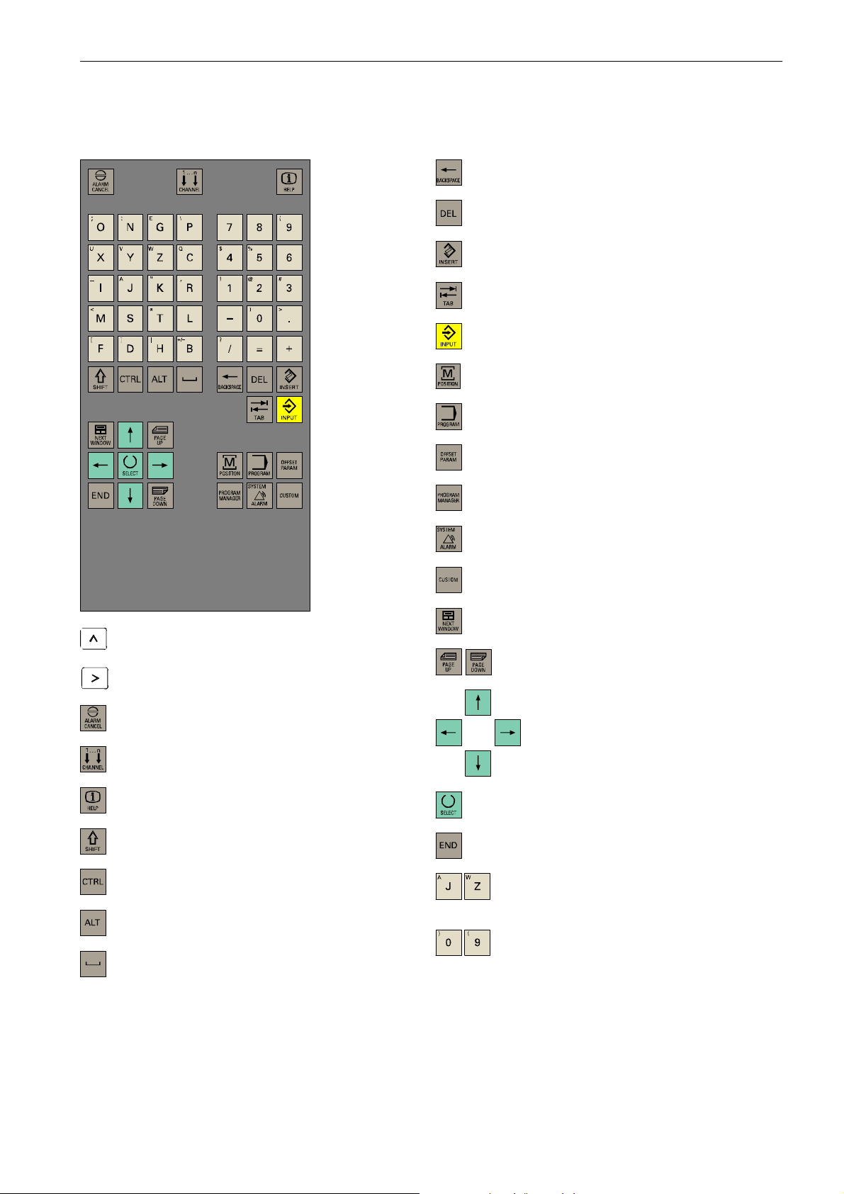
Key definition of the full CNC keyboard (vertical format)
Key definition of the full CNC keyboard (vertical format)
Delete key (Backspace)
&
Delete key
Insert key
Tabulator
ENTER/Input key
”Position” operating area key
”Program” operating area key
”Parameter” operating area
”Program Manager” operating area key
”Alarm/System” operating area
Recall key
ETC key
”Acknowledge alarm” key
without function
Info key
Shift key
Control key
Alt key
SPACE
not assigned
PageUp/PageDown keys
Cursor keys
Selection key/toggle key
Alphanumeric keys
Double assignment on the Shift level
Numeric keys
Double assignment on the Shift level
SINUMERIK 802D sl Operation and Programming Turning (BP-- D), 10/2006 Edition
6FC5 398--1CP10--2BA0
ix
Page 10
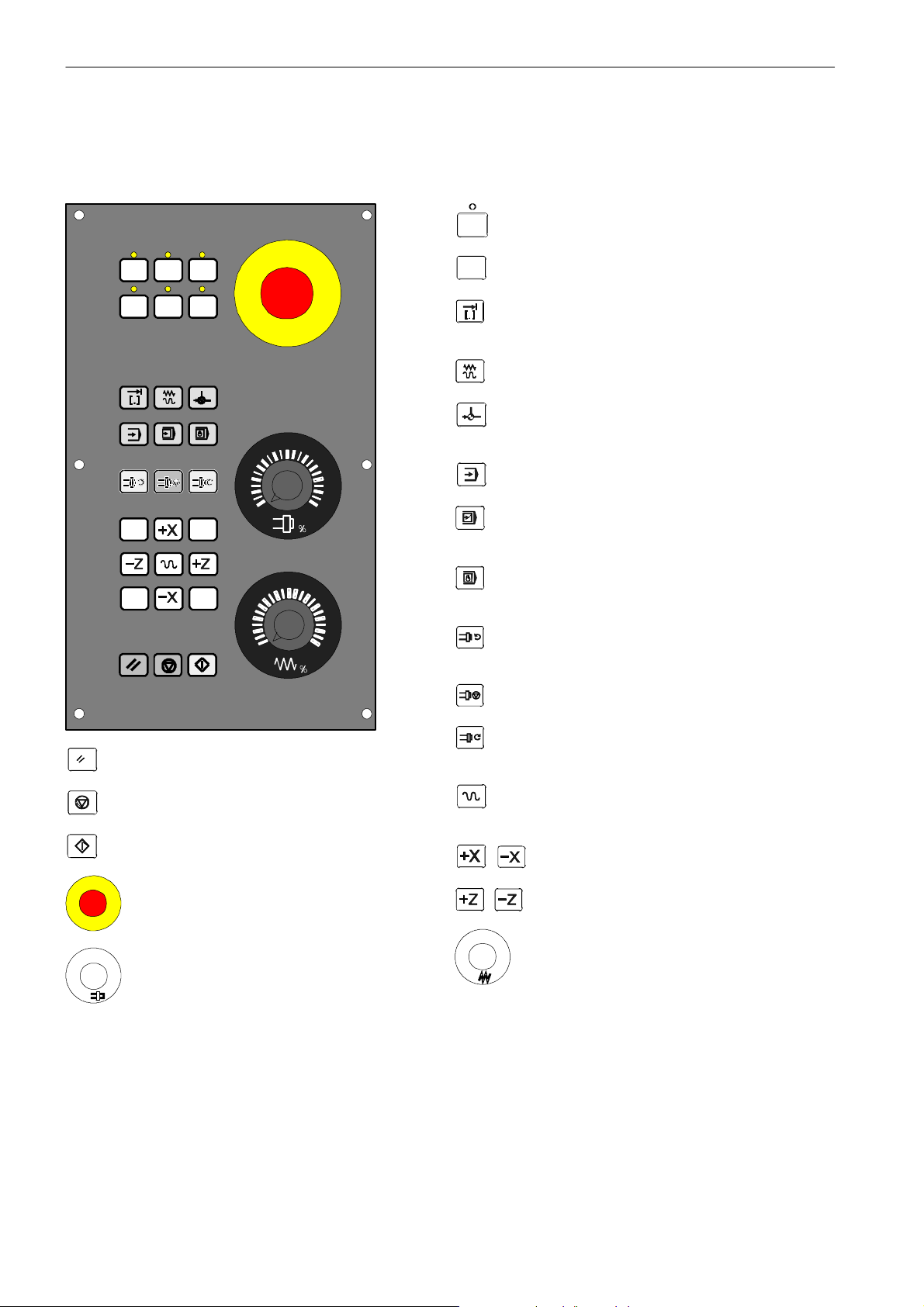
Key definition of the machine control panel
Key definition of the machine control panel
User--defined key with LED
User--defined key without LED
INCREMENT
Increment
JOG
REFERENCE POINT
80
70
60
90
100
110
120
Reference point
AUTOMATIC
SINGLE BLOCK
Single block
60
70
40
20
10
6
2
0
80
90
100
110
120
MANUAL DATA
Manual input
SPINDLE START LEFT
Counterclockwise
SPINDLE STOP
SPINDLE START RIGHT
RESET
NC STOP
NC START
Clockwise
RAPID TRAVERSE OVERLAY
Rapid traverse override
X axis
Z axis
EMERGENCY STOP
%
%
Spindle override
Feedrate override
Feedrate control
x
SINUMERIK 802D sl Operation and Programming Turning (BP-- D), 10/2006 Edition
6FC5 398--1CP10--2BA0
Page 11
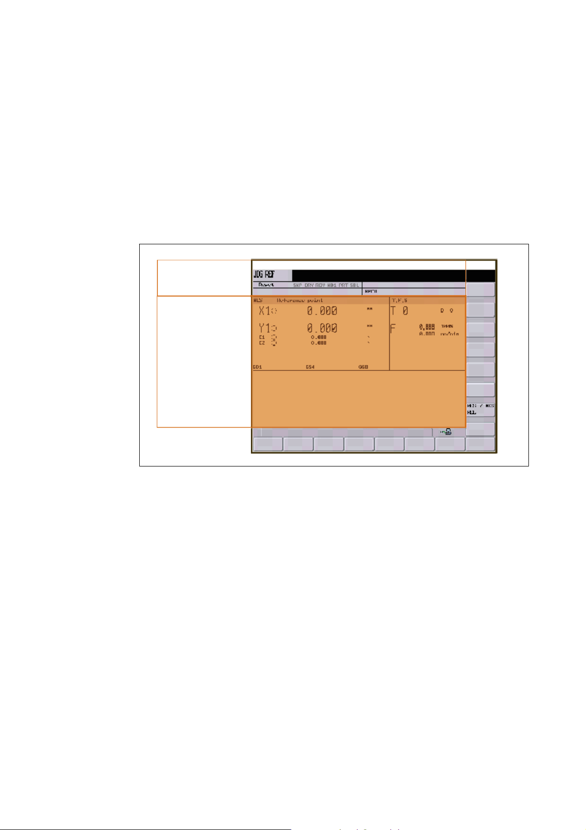
Introduction
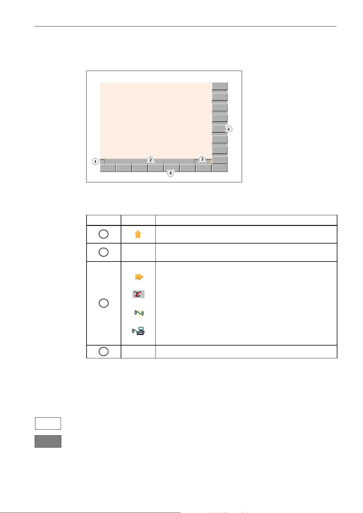
1.1 Screen layout
Status area
Application area
1
Tip
and softkey area
Fig. 1-1 Screen layout
The screen is divided into the following main areas:
S Status area
S Application area
S Tip and softkey area
SINUMERIK 802D sl Operation and Programming Turning (BP-- D), 10/2006 Edition
6FC5 398--1CP10--2BA0
1-11
Page 12
Introduction
MDA
y
Syste
m
A
1.Alarmnumberwithalarmtex
t,o
r
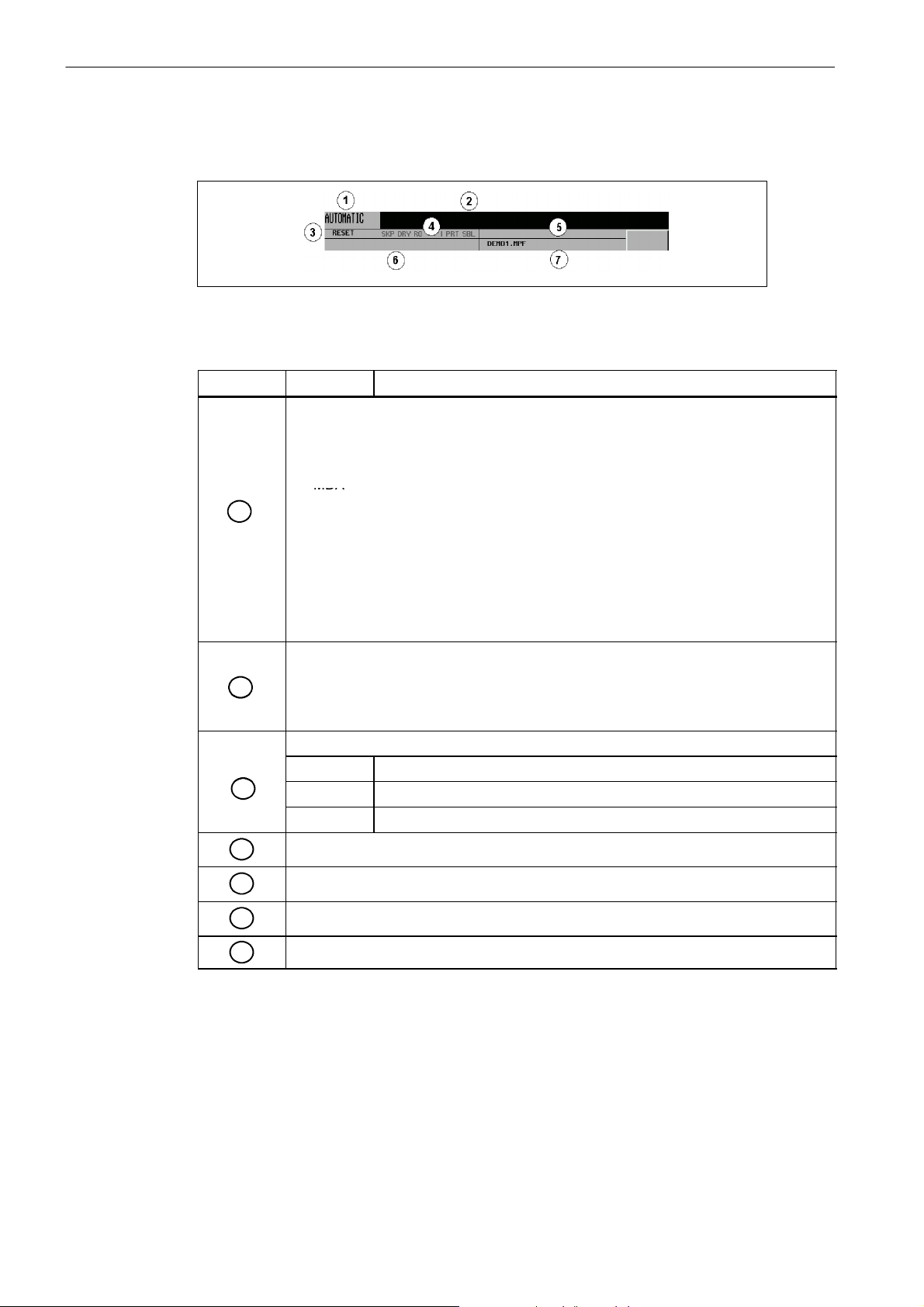
1.1 Screen layout
Status area
Fig. 1-2 Status area
Table 1-1 Explanation of the screen controls in the status area
Screen item
1
2
3
4
Display Meaning
Active operating area, active mode
Position
JOG: 1 INC, 10 INC, 100 INC, 1000 INC, VAR INC (evaluation by increments in the
JOG mode)
MDA
AUTOMATIC
Offset
Program
Program Manager
S
stem
Interrupt
Marked as an ”external language” using G291
Alarm and message line
In addition, the following is displayed:
1.
larm number with alarm text,or
2. Message Text
Program status
RESET Program canceled/default status
RUN Program running
STOP Program stopped
Program controls in Automatic mode
5
6
7
1-12
Reserved
NC messages
Selected part program (main program)
SINUMERIK 802D sl Operation and Programming Turning (BP-- D), 10/2006 Edition
6FC5 398--1CP10--2BA0
Page 13
Tip and softkey area
Fig. 1-3 Tip and softkey area
Introduction
1.1 Screen layout
Table 1-2 Explanation of the screen controls in the tip and softkey area
Screen item
1
2
3
4
Display Meaning
Recall symbol
Pressing the Recall key lets you return to the next higher menu level.
Tip line
Displays tips for the operator
MMC status information
ETC is possible (Pressing this key displays the horizontal softkey bar
providing further functions.)
Mixed notation active (uppercase/lowercase letters)
Data transfer running
Connection to the PLC programming tool active
Vertical and horizontal softkey bar
Representation of the softkeys in the document
To make the softkeys easier to locate, the horizontal and vertical softkeys are represented
with different primary colors.
Horizontal softkey
Vertical softkey
SINUMERIK 802D sl Operation and Programming Turning (BP-- D), 10/2006 Edition
6FC5 398--1CP10--2BA0
1-13
Page 14

Introduction
1.1 Screen layout
Standard softkeys
Use this softkey to quit the screen form.
Use this softkey to cancel the input; the window is closed.
Selecting this softkey will complete your input and start the calculation.
Selecting this softkey will complete your input and accept the values you have entered.
This function is used to switch the screen form from diameter programming to radius programming.
1-14
SINUMERIK 802D sl Operation and Programming Turning (BP-- D), 10/2006 Edition
6FC5 398--1CP10--2BA0
Page 15
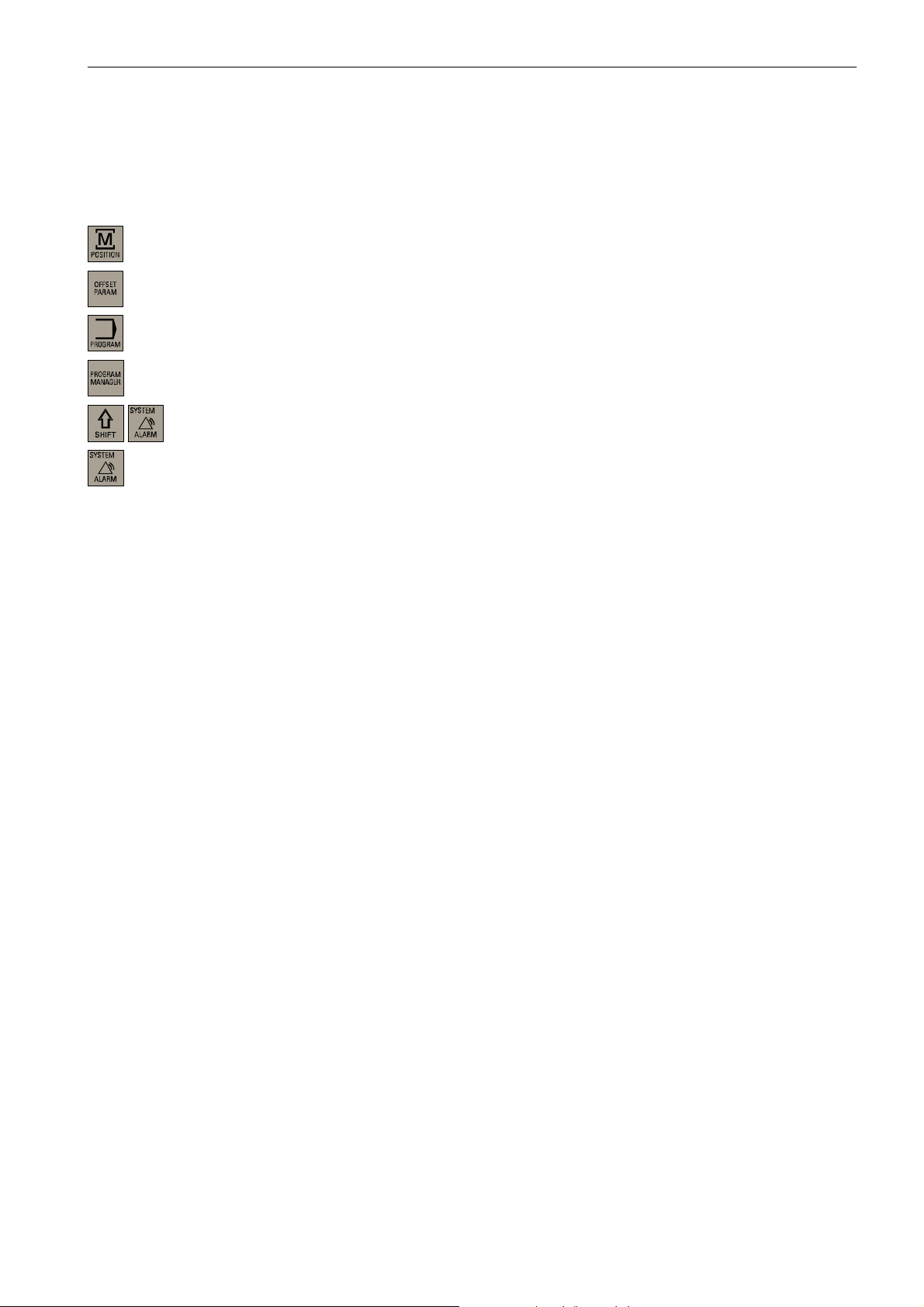
1.2 Operating areas
The functions of the control system can be carried out in the following operating areas:
Position Machine operation
Offset/Parameters Input of offset values and setting data
Program Creation of part programs
Program Manager Part program directory
System Diagnosis, start--up
Alarm Alarm and message lists
Introduction
1.2 Operating areas
Protection levels
To switch the operating area, use the relevant key (hard key).
The SINUMERIK 802D sl provides a concept of protection levels for enabling data areas.
The control system is delivered with default passwords for the protection levels 1 to 3.
Protection level 1 Expert password
Protection level 2 Manufacturer password
Protection level 3 User password
These control the individual access authorizations.
In the menus listed below the input and modification of data depends on the protection level set:
S Tool offsets
S Work offsets
S Setting data
S RS232 settings
S Program creation/program editing
SINUMERIK 802D sl Operation and Programming Turning (BP-- D), 10/2006 Edition
6FC5 398--1CP10--2BA0
1-15
Page 16
Introduction
1.3 Accessibility options
1.3 Accessibility options
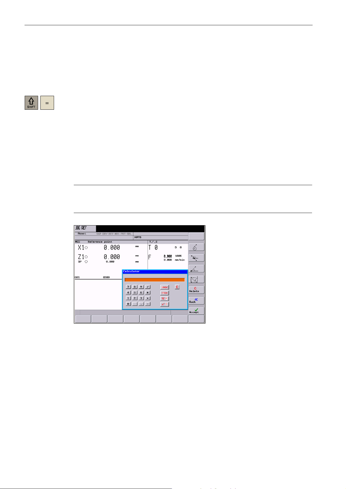
1.3.1 Calculator
The calculator function can be activated from any operating area using ”SHIFT” and ”=”.
To calculate terms, the four basic arithmetic operations can be used, as well as the functions
”sine”, ”cosine”, ”squaring” and ”square root”. A bracket function is provided to calculate
nested terms. The bracket depth is unlimited.
If the input field is already occupied by a value, the function will accept this value into the
input line of the calculator.
When you press the Input key, the result is calculated and displayed in the calculator.
Selecting the Accept softkey enters the result in the input field at the current cursor position
of the part program editor and closes the calculator automatically.
Note
If an input field is in editing mode, it is possible to restore the original status using the
”Toggle” key.
Fig. 1-4 Pocket calculator
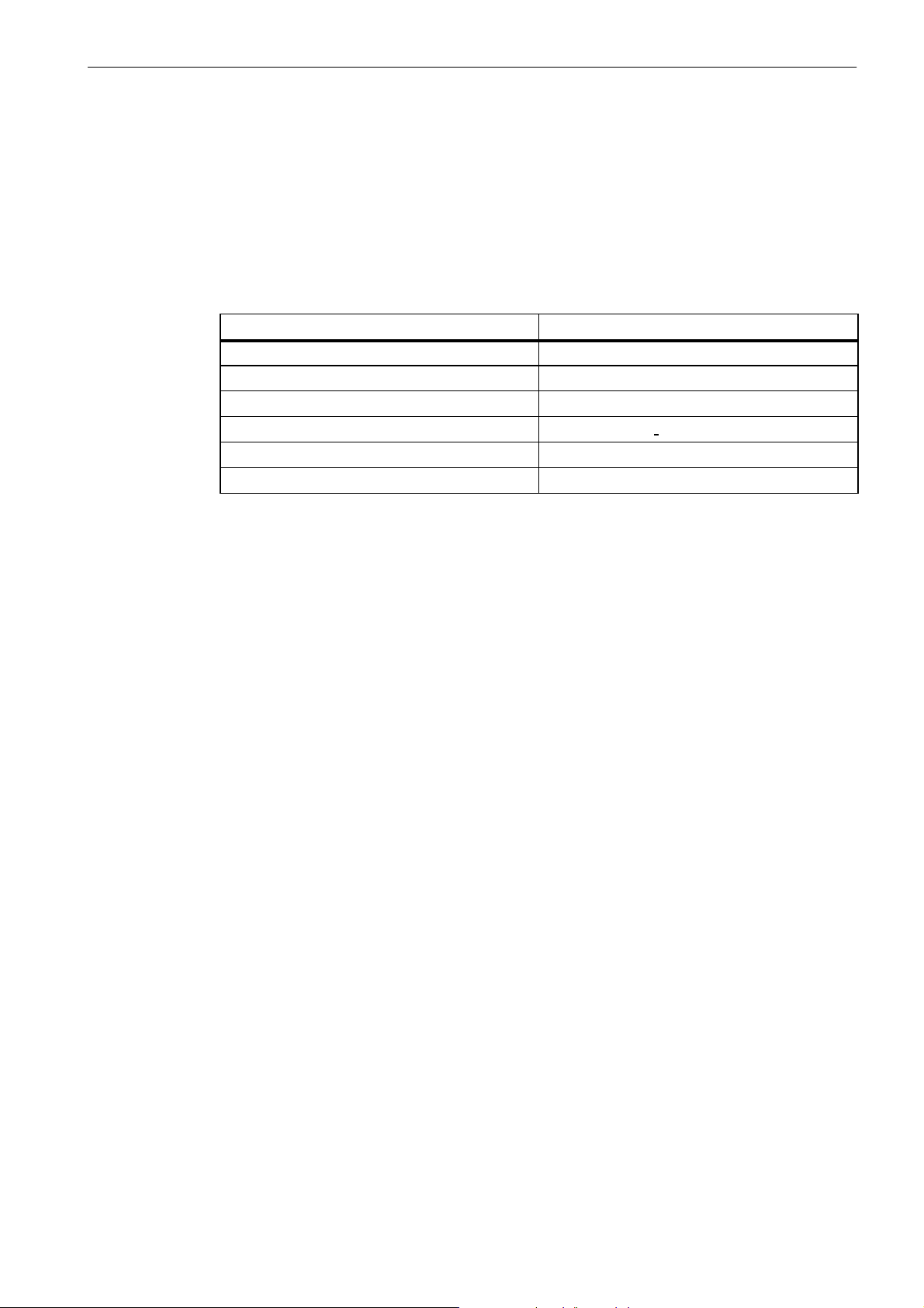
Characters permitted for input
1-16
+, --, *, / Fundamental operations of arithmetic
S Sine function
The X value (in degrees) in front of the input cursor is replaced by the sin(X) value.
O Cosine function
The X value (in degrees) in front of the input cursor is replaced by the cos(X) value.
SINUMERIK 802D sl Operation and Programming Turning (BP-- D), 10/2006 Edition
6FC5 398--1CP10--2BA0
Page 17
Introduction
1.3 Accessibility options
Q Square function
The X value in front of the input cursor is replaced by the X
R Square root function
The X value in front of the input cursor is replaced by the √X value.
( ) Bracket function (X+Y)*Z
Calculation examples
100 + (67*3) 100+67*3 --> 301
sin(45_) 45 S --> 0.707107
cos(45_) 45 S --> 0.707107
2
4
√4 4R -->2
(34+3*2)*10 (34+3*2)*10 --> 400
To calculate auxiliary points on a contour, the calculator offers the following functions:
S Calculating the tangential transition between a circle sector and a straight line
S Moving a point in the plane
2
value.
Task Input --> Result
4Q -- > 1 6
S Converting polar coordinates to Cartesian coordinates
S Adding the second end point of a straight line/straight line contour section given from an
angular relation
SINUMERIK 802D sl Operation and Programming Turning (BP-- D), 10/2006 Edition
6FC5 398--1CP10--2BA0
1-17
Page 18
Introduction
1.3 Accessibility options
1.3.2 Aligning contour elements
When you open the calculator, softkeys for editing contour elements appear. You enter the
values for the contour element in the respective input screens. Press ”Accept” to perform the
calculation.
Softkeys
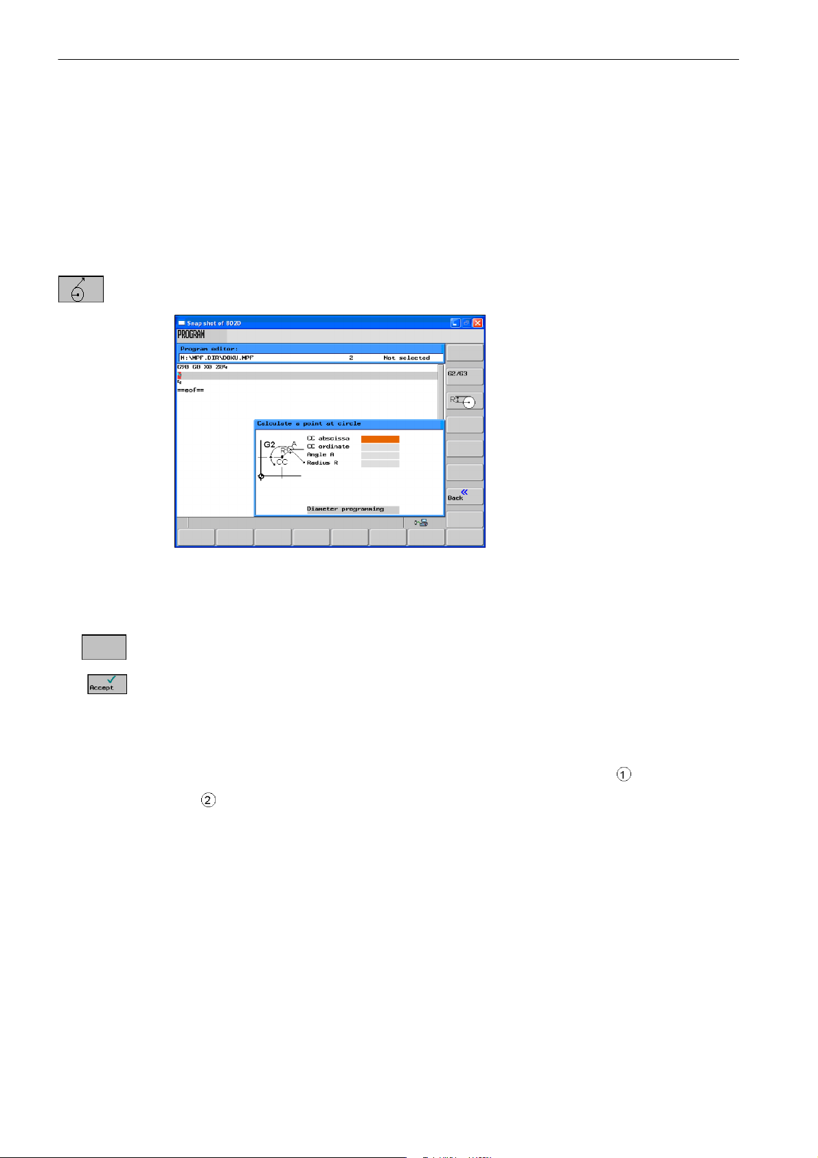
This function is used to calculate a point on a circle. The point results from the angle of the
tangent created, as well as from the radius and the direction of rotation of the circle.
G2/G3
Fig. 1-5
Enter the circle center, the angle of the tangent and the circle radius.
Use the G2/G3 softkey to define the direction of rotation of the circle.
Use this softkey to calculate the abscissa and ordinate values. The abscissa is the first axis,
and the ordinate is the second axis of the plane. The abscissa value is copied into the input
field from which the calculator function has been called, and the value of the ordinate is copied into the next following input field. If the function has been called from the part program
editor, the coordinates are saved with the axis names of the selected basic plane.
Example: Calculating the point of intersection between the circle sector
line
in plane G18.
and the straight
Given: Radius: 10
Circle center: Z 147 X 103
Connection angle of the straight line: --45
°
1-18
SINUMERIK 802D sl Operation and Programming Turning (BP-- D), 10/2006 Edition
6FC5 398--1CP10--2BA0
Page 19
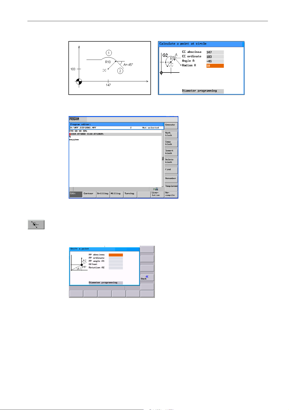
X
XZ
Result: Z = 154.071
X = 110.071
Introduction
1.3 Accessibility options
Z
Fig. 1-6
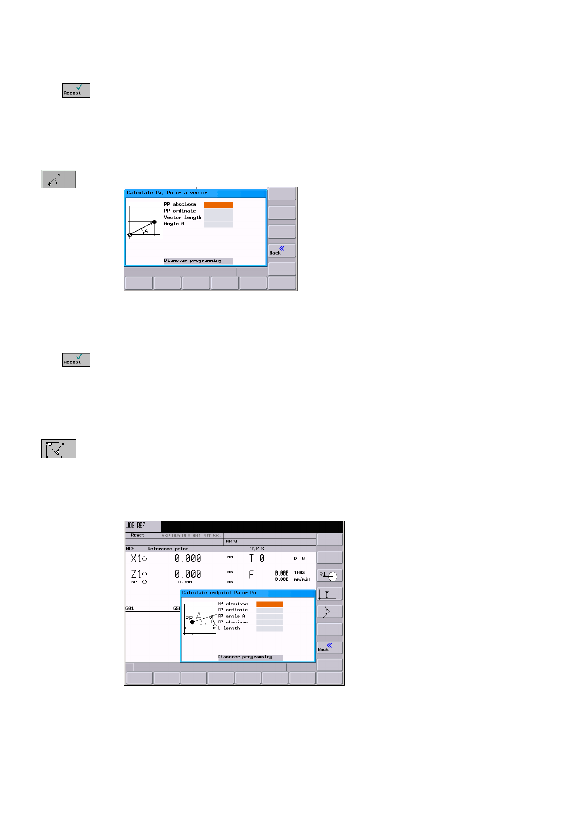
This function calculates the Cartesian coordinates of a point in the plane, which is to be connected to a point in the plane (PP) on a straight line. For calculation, the distance between
the points and the slope angle (A2) of the new straight line to be created with reference to
the slope (A1) of the given straight line must be known.
Fig. 1-7
Enter the following coordinates or angles:
S the coordinates of the given point (PP)
S the slope angle of the straight line (A1)
S the distance of the new point with reference to PP
S the slope angle of the connecting straight line (A2) with reference to A1
SINUMERIK 802D sl Operation and Programming Turning (BP-- D), 10/2006 Edition
6FC5 398--1CP10--2BA0
1-19
Page 20
Introduction
1.3 Accessibility options
Use this softkey to calculate the Cartesian coordinates which are subsequently copied into
two input fields following one after another. The abscissa value is copied into the input field
from which the calculator function has been called, and the value of the ordinate is copied
into the next following input field.
If the function has been called from the part program editor, the coordinates are saved with
the axis names of the selected basic plane.
This function converts the given polar coordinates into Cartesian coordinates.
Fig. 1-8
Enter the reference point, the vector length and the slope angle.
Use this softkey to calculate the Cartesian coordinates which are subsequently copied into
two input fields following one after another. The abscissa value is copied into the input field
from which the calculator function has been called, and the value of the ordinate is copied
into the next following input field.
If the function has been called from the part program editor, the coordinates are saved with
the axis names of the selected basic plane.
Use this function to calculate the missing end point of the straight line/straight line contour
section whereby the second straight line stands vertically on the first straight line.
The following values of the straight line are known:
Straight line 1: Starting point and slope angle
Straight line 2: Length and one end point in the Cartesian coordinate system
1-20
Fig. 1-9
SINUMERIK 802D sl Operation and Programming Turning (BP-- D), 10/2006 Edition
6FC5 398--1CP10--2BA0
Page 21
Introduction
1.3 Accessibility options
This function is used to select the given coordinate of the end point.
The ordinate value or the abscissa value is given.
The second straight line is rotated in the CW direction or in the CCW direction by 90 degrees
relative to the first straight line.
The missing end point is calculated. The abscissa value is copied into the input field from
which the calculator function has been called, and the value of the ordinate is copied into the
next following input field.
If the function has been called from the part program editor, the coordinates are saved with
the axis names of the selected basic plane.
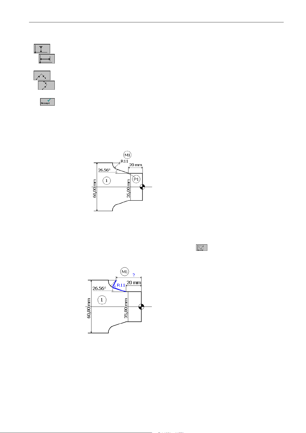
Example
Fig. 1-10
Add the drawing above by the value of the center circle in order to be able to calculate the
intersection point between the circle sector of the straight line. The missing center point
coordinate is calculated using the calculator function
, as the radius in the tangential
transition stands vertically on the straight line.
Fig. 1-11
Calculating M1 in section 1:
The radius stands at an angle of 90° turned CW on the straight--line defined by the angle.
SINUMERIK 802D sl Operation and Programming Turning (BP-- D), 10/2006 Edition
6FC5 398--1CP10--2BA0
1-21
Page 22
Introduction
1.3 Accessibility options
Use the softkey to select the appropriate direction of rotation. Use the softkey
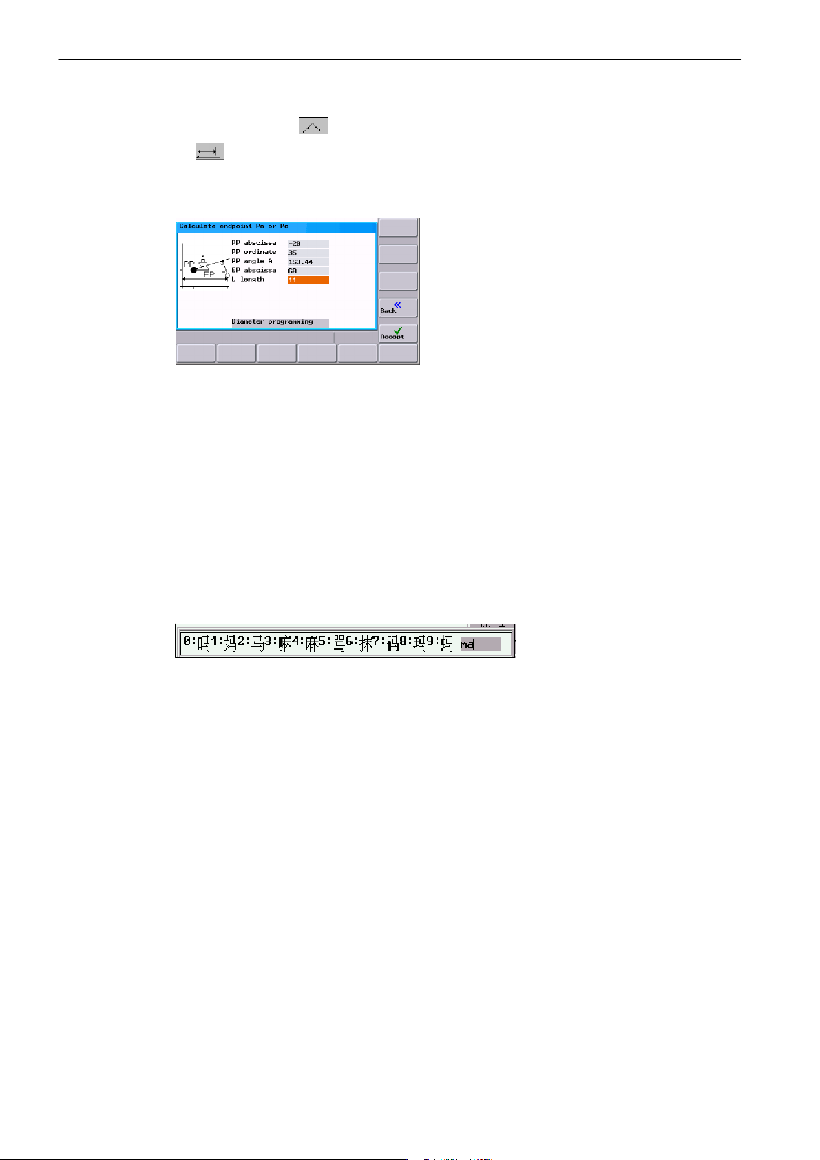
Enter the coordinates of the pole, the slope angle of the straight line, the ordinate angle
of the end point and the circle radius as the length.
Fig. 1-12
Result: X = 60
to define the given end point.
Z = --44.601
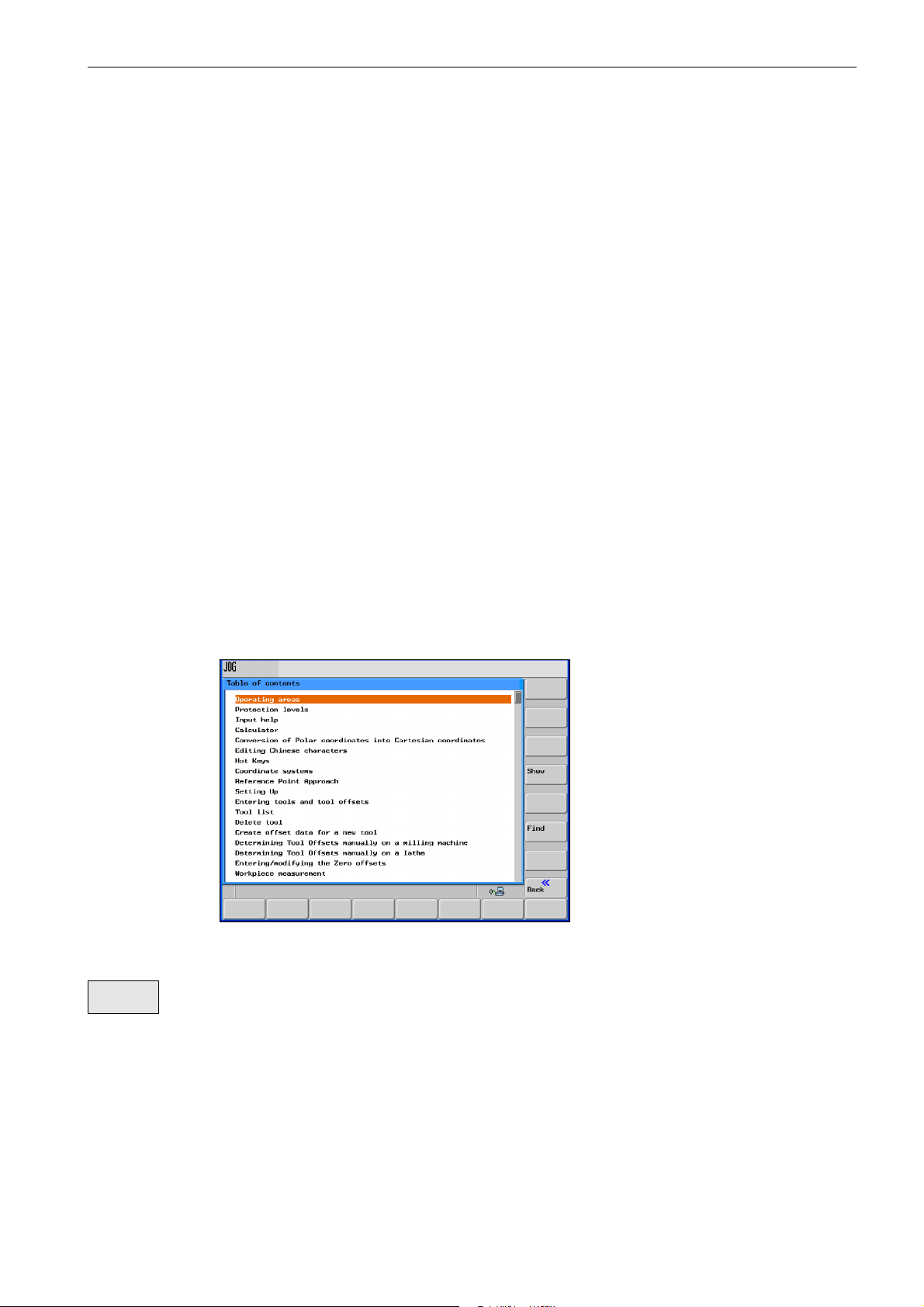
1.3.3 Editing Chinese characters
This function is only available in the Chinese language version.
The control system provides a function for editing Chinese characters in the program editor
and in the PLC alarm text editor. After activation, type the phonetic alphabet of the searched
character in the input field. The editor will then offer various characters for this sound, from
which you can choose the desired one by entering either of the digits 1 to 9.
Fig. 1-13 Chinese editor
Alt S Use this key combination to turn on/off the editor
1.3.4 Hotkeys
This operator control can be used to select, copy, cut and delete texts using special key
commands. These functions are available both for the part program editor and for input
fields.
CTRL C Copy
CTRL B Select
CTRL X Cut
CTRL V Paste
Alt L Switch between uppercase/lowercase letters
Alt H Help system
or Info key
1-22
SINUMERIK 802D sl Operation and Programming Turning (BP-- D), 10/2006 Edition
6FC5 398--1CP10--2BA0
Page 23
1.3.5 Copying and pasting files
In the Program Manager area (Section 6) and with the Start--up files function (Section
7.6), files or even complete directories can be copied into another directory or to another
drive using the softkey functions Copy and Paste. When doing so, the Copy function enters
the references to the files or directories in a list which is subsequently executed by the Paste
function. This function will perform the actual copying process.
The list is kept until a new copying process overwrites this list.
Special feature:
If the RS232 interface has been selected as the data target, the Paste function is replaced
by the Send softkey function. When reading in files ( Receive) softkey), it is not necessary
to specify a target, since the name of the target directory is not contained in the data flow.
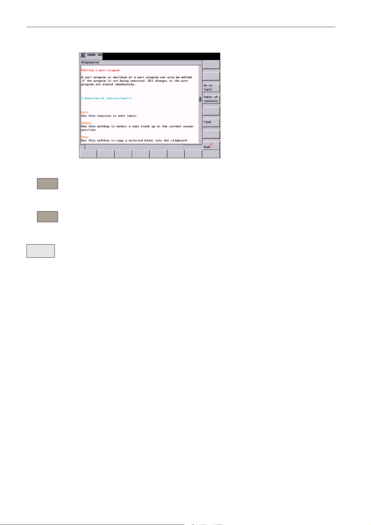
1.4 The help system
Introduction
1.4 The help system
To activate the help system, use the Info key. It offers a brief description for all important
operating functions.
In addition, the help function offers the following topics:
S Overview of the NC commands with a brief description
S Cycle programming
S Explanation of the drive alarms
Fig. 1-14 Table of contents of the help system
Show
SINUMERIK 802D sl Operation and Programming Turning (BP-- D), 10/2006 Edition
6FC5 398--1CP10--2BA0
This function opens the selected topic.
1-23
Page 24
Introduction
1.4 The help system
Fig. 1-15 Description for a help topic
Go to
topic
Use this function to select cross references. A cross reference is marked by the characters
”>>....<<”. This softkey is only unhidden if a cross reference is displayed in the application
area.
Back to
topic
Use this function to select a cross reference; in addition, the Back to topic softkey is displayed.
Select this function to go back to the previous screen.
Find
Use this function to search for a term in the table of contents. Type the term you are looking
for and start the search process.
Help in the ”Program editor” a rea
The system offers an explanation for each NC instruction. To display the help text directly,
position the cursor after the appropriate instruction and press the Info key.
1-24
SINUMERIK 802D sl Operation and Programming Turning (BP-- D), 10/2006 Edition
6FC5 398--1CP10--2BA0
Page 25
1.5 Network operation (optional)
Note
The network function is only available for SINUMERIK 802D sl.
Thanks to the integrated network adapter, the control system is network--capable. The following connections are possible:
S Peer--to--Peer: Direct connection between control system and PC using a cross--over
cable
S Twisted Pair: Integration of the control system into an existing, local network using a
patch cable.
Screened network operation with encrypted data transfer is possible using an 802D specific
transmission protocol. This protocol is used, e.g. for transmitting and executing part programs in conjunction with the RCS tool.
Introduction
1.5 Network operation (optional)
1.5.1 Configuring the network connection
Requirement
The control system is connected to the PC or the local network via the X5 interface.
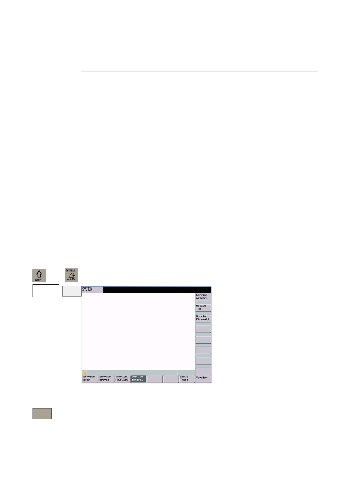
Entering network parameters
In the ”System” operating area, select the Service display > Service control menu.
Service
display
plus
Service
control
Fig. 1-16
Service
network
SINUMERIK 802D sl Operation and Programming Turning (BP-- D), 10/2006 Edition
6FC5 398--1CP10--2BA0
Select the Service network softkey to obtain access to the input screen to input the network
parameters.
1-25
Page 26
Introduction
1.5 Network operation (optional)
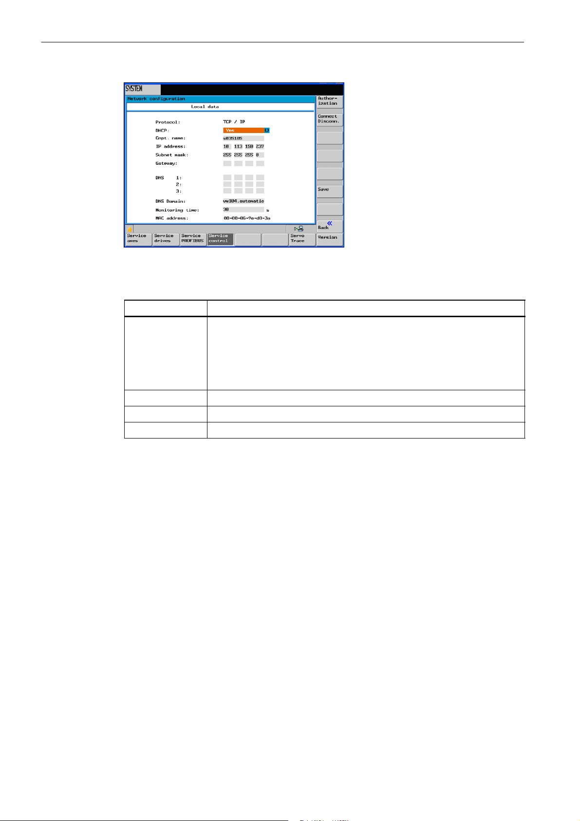
Fig. 1-17
Table 1-3 Required network parameters
Parameter
DHCP A TCP/IP service protocol which offers the dynamically leased configuration of
host IP addresses and thus distributes meaningful configuration parameters to
authorized network clients.
If you enter here No, the network addresses are fixed.
If you enter Yes, the network addresses are assigned dynamically. Input fields
that are no longer needed are hidden.
Cmpt. name Name of the control system in the network
IP address Network address of the control system (e.g. 192.168.1.1)
Subnet mask Network identification (e.g. 255.255.252.0)
Explanation
1-26
SINUMERIK 802D sl Operation and Programming Turning (BP-- D), 10/2006 Edition
6FC5 398--1CP10--2BA0
Page 27
Enabling the communication ports
Introduction
1.5 Network operation (optional)
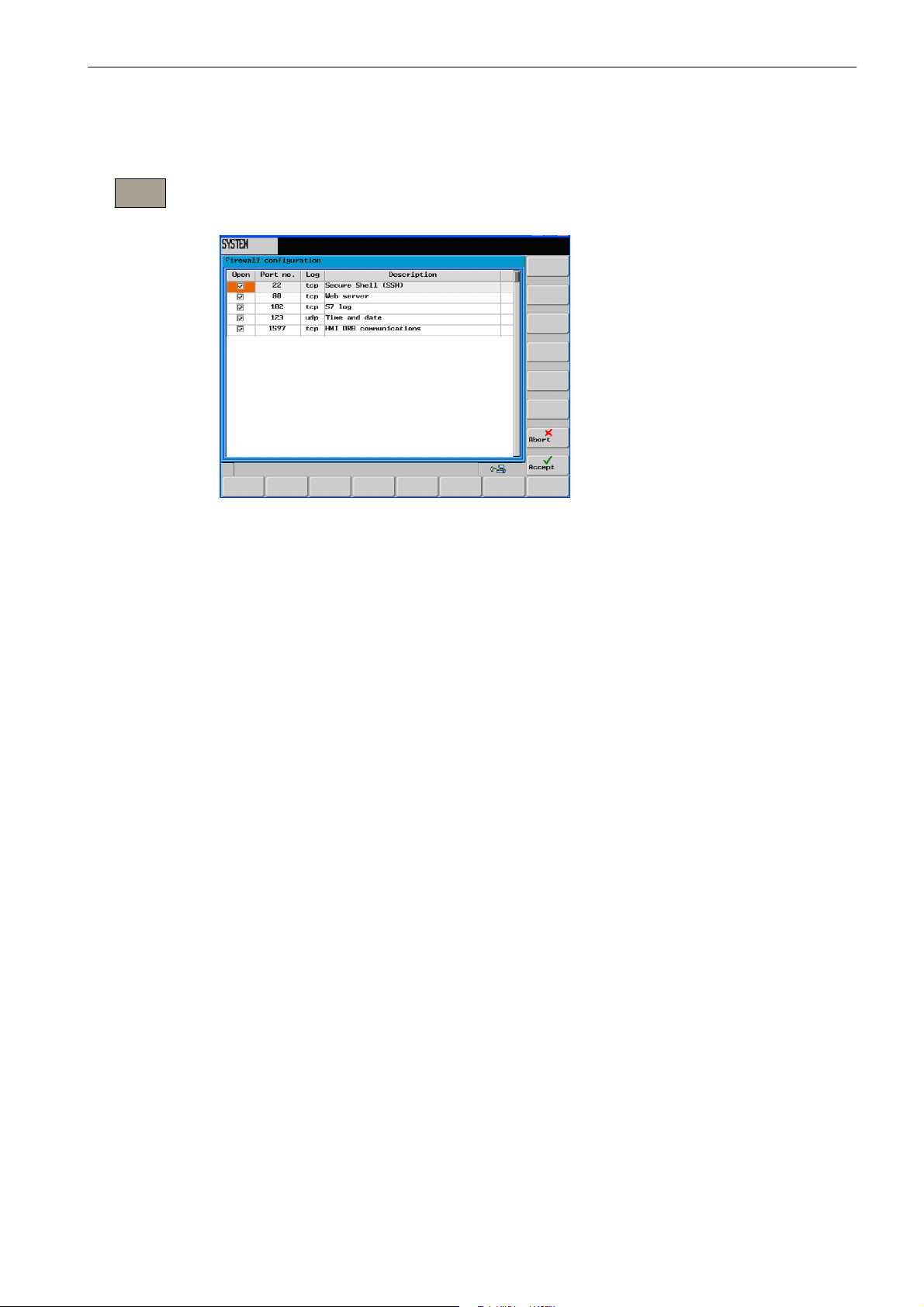
Service
Firewall
Use the ”Service Firewall” softkey to enable or disable communication ports.
To ensure maximum possible safety, all ports not needed should be closed.
Fig. 1-18
The RCS network requires the ports 80 and 1597 for communication.
To change the port status, select the relevant port using the cursor. Pressing the INPUT key
changes the port status.
Open ports are shown with the check box enabled.
SINUMERIK 802D sl Operation and Programming Turning (BP-- D), 10/2006 Edition
6FC5 398--1CP10--2BA0
1-27
Page 28
Introduction
1.5 Network operation (optional)
1.5.2 User management
Service
display
Service
network
plus
Service
control
Authoriz
ation
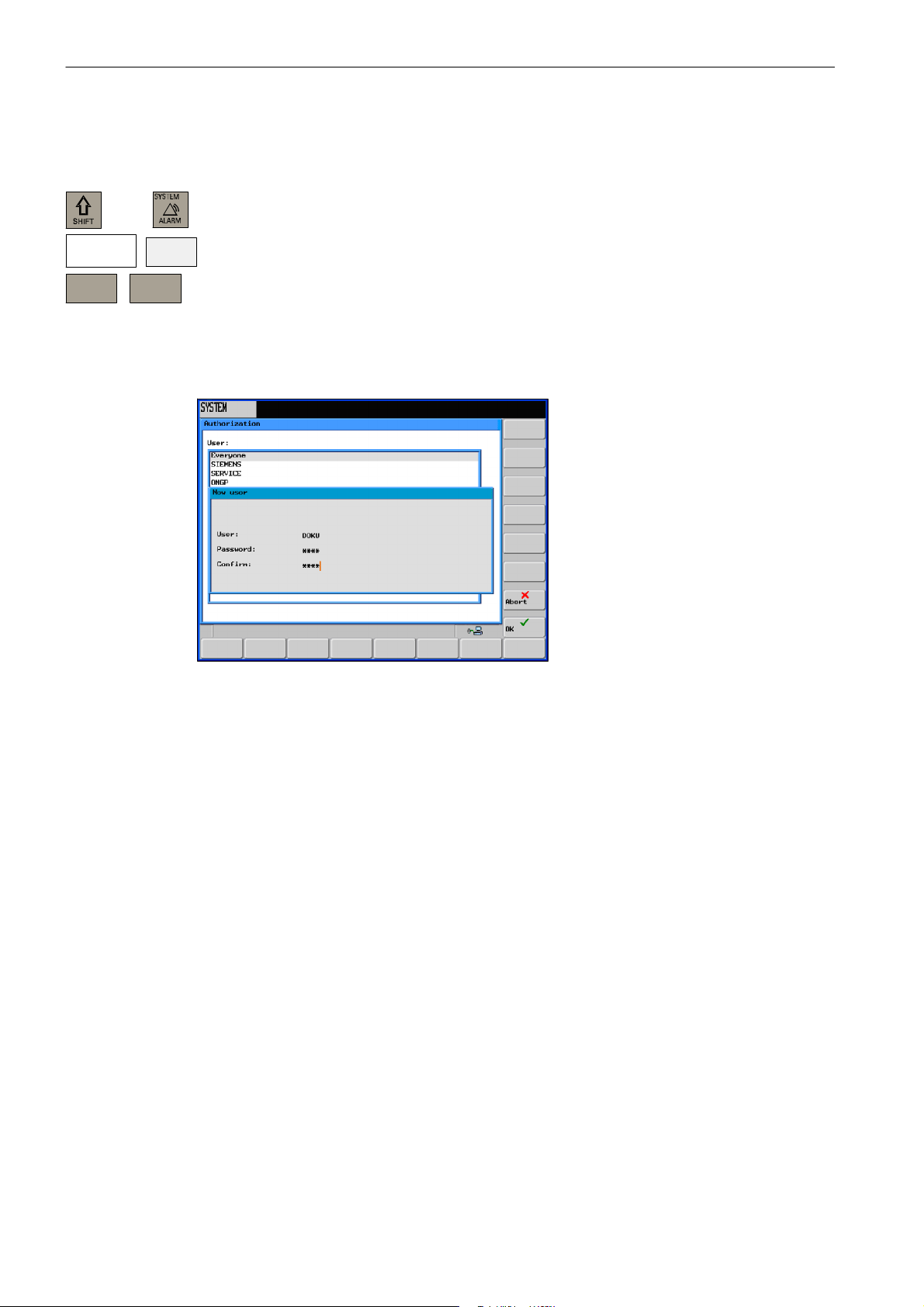
In the ”System” operating area, select the Service display > Service control menu.
Select the Service network > Authorization softkey to obtain access to the input screen to
input the network parameters.
The user accounts serve for saving personal settings of the users. To create a new account,
type the user name and the log--in password in the input fields.
Use the Create softkey to insert a new user into the user management.
Fig. 1-19
Use the Delete softkey to delete the selected user from the user management.
1-28
SINUMERIK 802D sl Operation and Programming Turning (BP-- D), 10/2006 Edition
6FC5 398--1CP10--2BA0
Page 29
1.5.3 User log--in -- RCS log-in
Introduction
1.5 Network operation (optional)
plus
RCS
log--in
Logging in
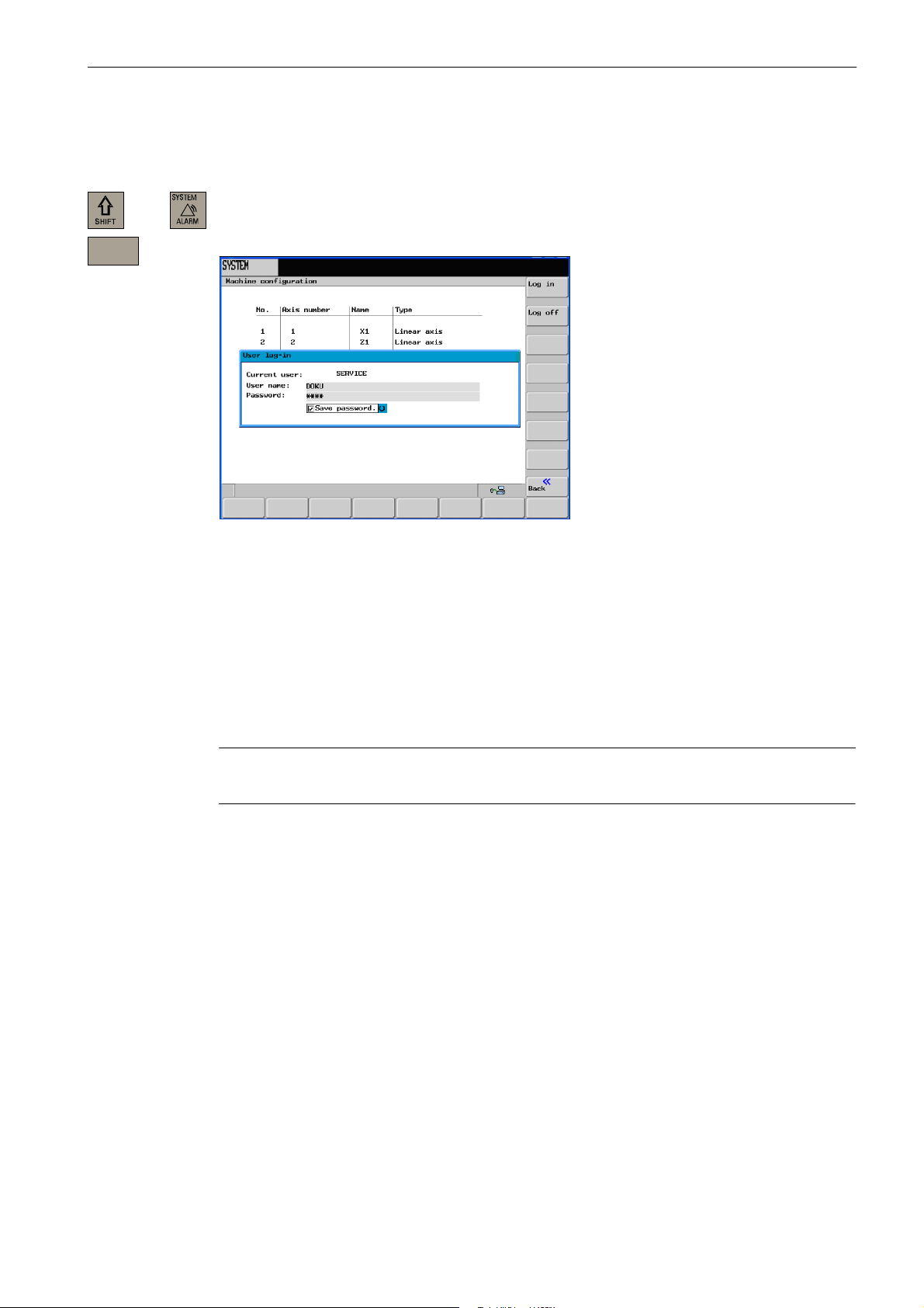
In the ”System” operating area, select the RCS log--in softkey.
Use this softkey to open the input screen for the user login.
Fig. 1-20 User log--in
Type a user name and the password in the appropriate input fields and select the Log in
softkey to confirm.
Logging out
After successful log--in, the user name is displayed in the Current user line.
Select the Back softkey to quit the dialog box.
Note
This log--in simultaneously serves for user identification for remote connections.
Select the Log out softkey. This will log out the current user, all user--specific settings are
saved, and any enables already granted are canceled.
SINUMERIK 802D sl Operation and Programming Turning (BP-- D), 10/2006 Edition
6FC5 398--1CP10--2BA0
1-29
Page 30

Introduction
1.5 Network operation (optional)
1.5.4 Working with a network connection
Remote access (access to the control system from a PC or from a network) to the control
system is disabled by default.
After log--in of a local user, the RCS tool are offered the following functions:
S Start--up functions
S Data transfer (transfer of part programs)
S Remote control for the control system
To grant access to a part of the file system, first share the relevant directories with other
users.
Note:
If you share directories with other users, the authorized network nodes are granted access
to the shared files in the control system. Depending on the sharing option, the user can
modify or delete files.
1.5.5 Sharing directories
This function defines the rights for access of remote users to the file system of the control
system.
Use the Program Manager to select the directory you want to share.
More...
Shares
Press More...
Use the Shares softkey to open the input screen for sharing the selected directory.
1-30
SINUMERIK 802D sl Operation and Programming Turning (BP-- D), 10/2006 Edition
6FC5 398--1CP10--2BA0
Page 31

1.5 Network operation (optional)
Fig. 1-21 Sharing status of the directory
S Select the sharing status for the selected directory:
-- Don’t share directory The directory is not shared with other users.
Introduction
-- Share directory The directory is shared with other users; enter a sharing name.
S In the Share name field, type an identifier with which authorized users can access the
files in the shared directory.
S Define the access rights.
-- Full access Grants the user full access.
-- Change The user is granted to right to modify files.
-- Read The user is only entitled to read files.
-- Delete The user is granted the right to delete files.
S Subsequently, select a user from the list of users. To switch to the list, use the TAB key.
Select the OK softkey to set the specified properties. As in Windows, shared directories are
marked with a ”hand”.
1.5.6 Connecting/disconnecting network drives
In the ”System” operating area, select the Service display > Service control menu.
Select Service network >Connect Disconn to obtain access to the network drive configu-
ration area.
Service
display
Service
network
plus
Service
control
Connect
Disconn
SINUMERIK 802D sl Operation and Programming Turning (BP-- D), 10/2006 Edition
6FC5 398--1CP10--2BA0
1-31
Page 32

Introduction
1.5 Network operation (optional)
Fig. 1-22
Connecting network drives
Connect
The Connect function assigns a network drive a local drive letter.
Fig. 1-23 Network drive configuration
Position the cursor on a free drive letter and use the TAB key to switch to the Path input
field. Enter the IP address and the sharing name in this field.
Example:
\\192.4.5.23\TEST\
The Connect softkey assigns the server connection a drive letter.
Disconnecting network drives
Dis-connect
1-32
Use the Disconnect function to disconnect a shared drive/directory from the network.
SINUMERIK 802D sl Operation and Programming Turning (BP-- D), 10/2006 Edition
6FC5 398--1CP10--2BA0
Page 33

Introduction
1.5 Network operation (optional)
Fig. 1-24
Position the cursor on the appropriate drive letter and select the Disconnect softkey. The
appropriate drive is disconnected from the network.
SINUMERIK 802D sl Operation and Programming Turning (BP-- D), 10/2006 Edition
6FC5 398--1CP10--2BA0
1-33
Page 34

Introduction
1.6 RCS tool
1.6 RCS tool
With the RCS tool (Remote Control System), you are provided with an Explorer tool for your
PC/PG to assist you in your daily work with SINUMERIK 802D sl.
The connection between the control system and the PC/PG can be provided either via an
RS232 cable or a network (option).
Notice
The full functionality of the RCS tool is only provided after loading of the RCS 802 license
key.
With this key, the connection to the control system can be established via a local network
(only for SINUMERIK 802D sl pro) and the remote operating function and other functions
canbeused.
Without a license key, it is only possible to share local directories (on the PC/PG) for access
by the control system.
Fig. 1-25 Explorer window of the RCS tool
After starting, you are in offline mode. This means that you can manage files on your PC
only. In online mode, the Control 802D directory is also available to you for file exchange
with the control system. In addition, a remote control function is provided for process monitoring.
Note
The RCS tool provides a detailed online help function. For further details e.g. establishing a
connection, project management etc., please refer to this help menu.
1-34
SINUMERIK 802D sl Operation and Programming Turning (BP-- D), 10/2006 Edition
6FC5 398--1CP10--2BA0
Page 35

1.7 Coordinate systems
For machine tools, right--handed, right--angled coordinate systems are used. The movements on the machine are described as a relative movement between tool and workpiece.
+Z
Introduction
1.7 Coordinate systems
Fig. 1-26 Determination of the axis directions another to one; coordinate system for programming
when turning
Machine coordinate system (MCS)
How the coordinate system is located with reference to the machine, depends on the machine type concerned. It can be rotated in different positions.
+X
+Y
+X
+Z
+Z
+X
Fig. 1-27 Machine coordinates/machine axes using the example of a turning machine
The origin of this coordinate system is machine zero.
This point only represents a reference point defined by the machine manufacturer. It need
not be approachable.
The traversing range of the machine axes can lie in the negative range.
SINUMERIK 802D sl Operation and Programming Turning (BP-- D), 10/2006 Edition
6FC5 398--1CP10--2BA0
1-35
Page 36

Introduction
1.7 Coordinate systems
Workpiece coordinate system (WCS)
In addition, a clockwise--rotating, right--angled coordinate system is used to describe the
geometry of a workpiece in the workpiece program (see Figure 1-26).
The programmer can select any workpiece zero in the Z axis. In the X axis, it lies in the
turning center.
Fig. 1-28 Workpiece coordinate system
Relative coordinate system
In addition to the machine and workpiece coordinate systems, the control system provides a
relative coordinate system. This coordinate system is used for setting reference points that
can be freely selected and have no influence on the active workpiece coordinate system. All
axis movements are displayed relative to these reference points.
Clamping the workpiece
For machining, the workpiece is clamped on the machine. The workpiece must be aligned
such that the axes of the workpiece coordinate system run in parallel with those of the machine. Any resulting offset of the machine zero with reference to the workpiece zero is determined along the Z axis and entered in a data area intended for the settable work offset.In
the NC program, this offset is activated, e.g. using a programmed G54 (see also Section
8.2.7).
Workpiece
W - Workpiece zero
X
Workpiece
W
Z
Workpiece
1-36
X
Machine
M
Z
Machine
E.g.
Fig. 1-29 Workpiece on the machine
SINUMERIK 802D sl Operation and Programming Turning (BP-- D), 10/2006 Edition
Workpiece
G54
X
Workpiece
W
Z
Workpiece
6FC5 398--1CP10--2BA0
Page 37

Current workpiece coordinate system
The programmed work offset TRANS can be used to generate an offset with reference to
the workpiece coordinate system resulting in the current workpiece coordinate system (see
Section ”Programmable work offset: TRANS”).
Introduction
1.7 Coordinate systems
SINUMERIK 802D sl Operation and Programming Turning (BP-- D), 10/2006 Edition
6FC5 398--1CP10--2BA0
1-37
Page 38

Introduction
1.7 Coordinate systems
Space for your notes
1-38
SINUMERIK 802D sl Operation and Programming Turning (BP-- D), 10/2006 Edition
6FC5 398--1CP10--2BA0
Page 39

Turning On and Reference Point Approach
Note
When you turn on the SINUMERIK 802D and the machine, please also observe the
Machine Documentation, since turning on and reference point approach are
machine--dependent functions.
This documentation assumes an 802D standard machine control panel (MCP). Should you
use a different MCP, the operation may be other than described herein.
operating sequence
First, turn on the power supply of CNC and machine. After the control system has powered
up, you are in the ”Position” operating area, in Jog Ref mode.
The Reference point approach window is active.
2
Fig. 2-1 The ”Jog--Ref” start screen
Use the Ref key on the machine control panel to activate ”reference point approach”.
The ”Reference point approach” window (Figure 2-1) displays whether the axes are referenced (approached to their reference points).
Axis must be referenced
Axis has reached its reference point
SINUMERIK 802D sl Operation and Programming Turning (BP-- D), 10/2006 Edition
6FC5 398--1CP10--2BA0
2-39
Page 40

Turning On and Reference Point Approach
+X
...
-Z
Press a direction key.
If you select the wrong approach direction, no motion is carried out.
Approach the reference points for each axis one after the other.
Quit the function by switching the mode (MDA, Automatic or Jog).
Note
”Reference point approach” is only possible in Jog Ref mode.
2-40
SINUMERIK 802D sl Operation and Programming Turning (BP-- D), 10/2006 Edition
6FC5 398--1CP10--2BA0
Page 41

Setting Up
Preliminary remarks
Before you can work with the CNC, set up the machine, the tools, etc. on the CNC as follows:
S Enter the tools and the tool offsets.
S Enter/modify the work offset.
S Enter the setting data.
3.1 Entering tools and tool offsets
Functionality
The tool offsets consist of several data describing the geometry, the wear and the tool type.
Each tool contains various parameters whose number depends on the particular tool type.
Tools are identified by a number (T number).
See also Section 8.6 ”Tool and tool compensation”
3
Operating sequences
Use this softkey to open the ”Tool offset data” window which contains a list of the tools
created. Use the cursor keys and the Page Up/Page Down keys to navigate in this list.
Tool
List
Fig. 3-1 Tool list
SINUMERIK 802D sl Operation and Programming Turning (BP-- D), 10/2006 Edition
6FC5 398--1CP10--2BA0
3-41
Page 42

Setting Up
3.1 Entering tools and tool offsets
Enter the offsets by positioning the
S cursor bar on the input field to be changed,
S enter the value(s)
and either press Input or use a cursor key to confirm.
Softkeys
Tool
measure
Measur.
manual
Measure
auto
Calibrate
probe
Delete
tool
Extend
For special tools, use the softkey function
Extend
which provides a complete parameter list
which can be filled out.
Use this softkey to determine the tool compensation data.
Determining the tool offset data manually (see Section 3.1.2)
Determining the tool offset data semi--automatically (see Section 3.1.3)
Use this softkey to calibrate the sensing probe.
Use this softkey to delete the tool.
Use this function to display all parameters of a tool. For the meanings of the parameters,
please refer to the Section ”Programming”.
Edges
3-42
D>>
<< D
Fig. 3-2 Input screen for special tools
Opens a lower--level menu bar offering all functions required to create and display further
edges.
Use this softkey to select the next higher edge number.
Use this softkey to select the next lower edge number.
SINUMERIK 802D sl Operation and Programming Turning (BP-- D), 10/2006 Edition
6FC5 398--1CP10--2BA0
Page 43

Setting Up
3.1 Entering tools and tool offsets
New
tool edge
Reset
edge
Change
type
Find
New
tool
Use this softkey to create a new edge.
Use this softkey to reset all compensation values of the edge to zero.
This function is intended to change the tool type. Select the tool type using the appropriate
softkey.
Use this function to search for a tool by its number.
Use this softkey to create tool offset data for a new tool.
3.1.1 Create new tool
Operating sequence
New
tool
Tuning
Tool
This function offers another two softkey functions to select the tool type. After selecting the
tool type, type the desired tool number (max. 3 digits) in the input field.
Fig. 3-3 The ”New tool” window Input of the tool number
For milling and drilling tools, the machining directions must be selected.
Fig. 3-4 Selection of the machining direction for a milling tool
SINUMERIK 802D sl Operation and Programming Turning (BP-- D), 10/2006 Edition
6FC5 398--1CP10--2BA0
3-43
Page 44

Setting Up
3.1 Entering tools and tool offsets
OK
Select OK to confirm your input. A data record loaded with zero will be included in the tool
list.
3.1.2 Determining the tool offsets (manually)
Functionality
This function can be used to determine the unknown geometry of a tool T.
Requirement
The relevant tool is loaded. In JOG mode, you will approach the edge of the tool to a machine point whose machine coordinate values are known. This can be a workpiece with a
known geometry.
Procedure
Enter the reference point in the appropriate field Ø or Z0.
Please observe: Assignment of Length 1 or Length 2 to the axis is dependent on the tool
type (turning tool, drill).
For the turning tool, the reference point for the X axis is a diameter dimension!
Using the actual position of the point F (machine coordinate) and the reference point, the
control system can calculate the offset value assigned to length 1 or length 2 for the axis.
Note: You can also use a zero already determined (e.g value of G54). In this case, use the
edge of the tool to approach the workpiece zero point. If the edge is positioned directly at
workpiece zero, the reference point is zero.
F -- toolholder reference point
M -- machine zero
W -- workpiece zero
The offset value in the X axis is a diameter value.
X
Machine
M
Fig. 3-5 Determination of the length offsets using the example of a turning tool
Actual position X
Workpiece
e.g. G54
Length 1=?
Diameter
W
Length 2=?
F
Actual position Z
Z
Machine
3-44
SINUMERIK 802D sl Operation and Programming Turning (BP-- D), 10/2006 Edition
6FC5 398--1CP10--2BA0
Page 45

F -- toolholder reference point
M -- machine zero
W -- workpiece zero
X
Machine
Workpiece
Setting Up
3.1 Entering tools and tool offsets
Actual position Z
Fig. 3-6 Determination of the length offset using the example of a drill: Length 1/Z axis
Note
Figure 3-6 only applies if the variables are the machine data MD 42950 TOOL_LENGTH_TYPE
and MD 42940 TOOL_LENGTH_CONST≠ are ”0”; otherwise, length tool 2 will apply for the
milling and drilling tools (see also Manufacturer Documentation ”SINUMERIK 802D sl Operating
Instructions”)
Operating sequence
Tool
Measur.
In JOG mode, use the Tool Measur. softkey to open the list box for manual and semiautomatic measuring.
M
e.g. G55
W
Length 1=?
F
Z
Machine
.
Fig. 3-7 Selecting manual or semiautomatic measuring
Measur.
manual
SINUMERIK 802D sl Operation and Programming Turning (BP-- D), 10/2006 Edition
6FC5 398--1CP10--2BA0
Use this softkey to open the Tool Measur. window.
3-45
Page 46

Setting Up
3.1 Entering tools and tool offsets
Fig. 3-8 The ”Tool Measur.” window
S Either type the workpiece diameter in the ”Ø” field or the workpiece length in the ”Z0”
field. The machine coordinates and the values from the work offsets will apply.
When using a spacer, it is also possible to enter the thickness of the spacer for taking
into account.
S After selecting the Set length 1 or Set length 2 softkey, the control system will deter-
mine the searched length 1 or length 2 of the preselected axis. The offset value determined will be stored.
Save
position
Selecting this softkey will save the X position. Thereafter, you can traverse in the X direction.
Thus, it is possible to determine, for example, the workpiece diameter. The stored value of
the axis position will then be used for calculating the length offset.
The activation of the softkey is dependent on the display machine data 373
MEAS_SAVE_POS_LENGTH2 (see also Manufacturer Documentation ”SINUMERIK 802D
sl Operating Instructions”)
3-46
SINUMERIK 802D sl Operation and Programming Turning (BP-- D), 10/2006 Edition
6FC5 398--1CP10--2BA0
Page 47

3.1.3 Determining tool compensations using a probe
Operating sequence
Setting Up
3.1 Entering tools and tool offsets
Tool
Measur.
Measur.
Auto
Use this softkey to open the Tool Measur. window.
Fig. 3-9 The ”Tool Measur.” window
In this input screen, you can enter tool and cutting edge numbers. In addition, the edge posi-
tion is displayed after the
symbol.
After the screen form has been opened, the input fields are filled with the data of the tool
currently working.
Thetoolcanbeeither
S the currently active tool of the NC (loaded via a part program) or
S a tool loaded by the PLC.
If the tool was loaded by the PLC, the tool number in the input screen can be different than
that in the T, F, S window.
If you change the tool number, no automatic tool change will be performed using this function. The entered tool, however, are assigned measurement results.
Measuring process
Approach the probe using either the traversing keys or the handwheel.
After the ”Probe tripped”
measuring process is completed. During the automatic measurement, a dial gauge
displayed, which symbolizes the measuring process currently active.
has appeared, release the traversing key and wait until the
, is
SINUMERIK 802D sl Operation and Programming Turning (BP-- D), 10/2006 Edition
6FC5 398--1CP10--2BA0
3-47
Page 48

Setting Up
3.1 Entering tools and tool offsets
Note
To create the measuring program, the ”Safety clearance” parameters from the Settings screen
form and the feedrate from the Probe data screen form are used (see Section 3.1.5).
If several axes are moved simultaneously, no offset data can be calculated.
3.1.4 Determining the t o o l offsets using optical measuring instruments
Fig. 3-10 Measuring using an optical measuring instrument (for the T and D input fields, please refer
Measuring process
For measuring, traverse the tool until its tip appears in the crosshair. With a milling tool, use
the highest point of the cutting edge to determine the tool length.
Subsequently, select the Set length softkey to calculate the offset values.
3.1.5 Probe settings
Settings
Data
probe
The screen form below is used to store the coordinates of the probe and to set the axis feedrate for the automatic measuring process.
All position values refer to the machine coordinate system.
to ”Measuring using a probe”)
3-48
SINUMERIK 802D sl Operation and Programming Turning (BP-- D), 10/2006 Edition
6FC5 398--1CP10--2BA0
Page 49

Fig. 3-11 ”Probe data” input screen
Table 3-1
Setting Up
3.1 Entering tools and tool offsets
Absolute position P1 Absolute position of the probe in the Z-- direction
Absolute position P2 Absolute position of the probe in the X+ direction
Absolute position P3 Absolute position of the probe in the Z+ direction
Absolute position P4 Absolute position of the probe in the X-- direction
Feedrate Feedrate with which the tool approaches the probe
Calibrating the probe
Calibrate
probe
TheprobecanbecalibratedeitherintheSettings menu or in the Measure tool menu.
The four points of the probe must be approached.
For calibration, use a tool of the type 500 with tool tip position 3 or 4.
The offset parameters required to determine the four probe positions can be written to the
data records of two cutting edges.
Parameter
Meaning
Fig. 3-12 Calibrating the probe
SINUMERIK 802D sl Operation and Programming Turning (BP-- D), 10/2006 Edition
6FC5 398--1CP10--2BA0
3-49
Page 50

Setting Up
3.1 Entering tools and tool offsets
After the screen form has appeared, an animation signaling the step to be executed is displayed next to the current positions of the probe. This point must be approached with the
appropriate axis.
After the ”Probe tripped”
measuring process is completed. During the automatic measurement, a dial gauge
has appeared, release the traversing key and wait until the
, is
displayed, which symbolizes the measuring process currently active.
The positions delivered by the measuring program serve to calculate the real probe position.
The measuring function can be quit without approaching all positions. The points already
sensed are stored.
Note
To create the measuring program, the ”Safety clearance” parameters from the Settings
screen form and the feedrate from the Probe data screen form are used.
If several axes are moved simultaneously, no offset data can be calculated.
Use the Next Step function to skip a point if this is not needed for measuring.
3-50
SINUMERIK 802D sl Operation and Programming Turning (BP-- D), 10/2006 Edition
6FC5 398--1CP10--2BA0
Page 51

3.2 Entering/modifying a work offset
Functionality
After the reference point approach, the actual--value memory and thus also the actual--value
display are referred to the machine zero. A machining program, however, is always referred
to the workpiece zero. This offset must be entered as the work offset.
Operating sequences
Use Offset Parameter and Work Offset to select the work offset.
An overview of all settable work offsets will appear on the screen. The screen form addition-
Work
Offset
ally contains the values of the programmed work offset and the active scaling factors, the
”Mirroring active” status display and the total of all active work offsets.
Setting Up
3.2 Entering/modifying a work offset
Change
activated
Fig. 3-13 The ”Work offset” window
Position the cursor bar on the input field to be changed
and enter the value(s). Either move the cursor a press the Input key to accept the values
from the input fields into the work offsets.
The compensation values of the cutting edge come into effect immediately.
SINUMERIK 802D sl Operation and Programming Turning (BP-- D), 10/2006 Edition
6FC5 398--1CP10--2BA0
3-51
Page 52

Setting Up
3.2 Entering/modifying a work offset
3.2.1 Determining the work offset
Requirement
You have select the window with the relevant work offset (e.g. G54) and the axis you want to
determine for the offset.
Fig. 3-14 Determining the work offset -Z axis
Proceed as follows
Measure
workpiece
Select the ”Measure workpiece” softkey. The control system will switch to the ”Position”
operating area and will open the dialog box for measuring the work offsets. The selected
axis will appear as a softkey with a black background.
Then scratch the workpiece with the tool tip. In the field ”Set position to:”, type the position
you wish to assume the workpiece edge in the workpiece coordinate system.
F -- -toolholder reference point
M--- machine zero
W--- workpiece zero
X
Machine
M
Work offset Z=?
Workpiece
W
Length 2
F
Actual position Z
Z
Machine
Set work
offset
3-52
Fig. 3-15 Screen form Determine work offset in Z
Selecting this softkey will calculate the offset and display the result in the ”Offset” field.
SINUMERIK 802D sl Operation and Programming Turning (BP-- D), 10/2006 Edition
6FC5 398--1CP10--2BA0
Page 53

3.3 Programming setting data -- ”Parameter” operating area
3.3 Programming setting data -- ”Parameter” operating area
Functionality
You use the setting data to define the settings for the operating states. These can be
changed as necessary.
Operating sequences
Select Setting data using the Offset parameter and Setting data softkeys.
Setting Up
Setting
data
The Setting data softkey branches to another menu level where various control options can
be set.
Fig. 3-16 The Setting data start screen
JOG feedrate
Feedrate value in Jog mode
If the feedrate value is ”zero”, the control system will use the value stored in the machine
data.
Spindle
Spindle speed
Minimum/maximum
A limitation of the spindle speed in the ”Max.” (G26)/”Min.” (G25) fields can only be performed within the limit values defined in the machine data.
Programmed (limitation)
Programmable upper speed limitation (LIMS) at constant cutting rate (G96).
Dry run feed (DRY)
The feedrate which can be entered here will be used instead of the programmed feedrate
in Automatic mode if the ”Dry run feed” function is selected.
Start angle for thread cutting (SF)
For thread cutting, a start position for the spindle is displayed as the start angle. A multiple thread can be cut by changing the angle when the thread cutting operation is repeated.
SINUMERIK 802D sl Operation and Programming Turning (BP-- D), 10/2006 Edition
6FC5 398--1CP10--2BA0
3-53
Page 54

Setting Up
3.3 Programming setting data -- ”Parameter” operating area
Position the cursor bar on the input field you want to modify and enter the value(s).
Either press the Input key or move the cursor to confirm.
Softkeys
Work area
limit.
Time
counter
The working area limitation is active with geometry and additional axes. If you want to use a
working area limitation, its values can be entered in this dialog box. Selecting the Set Active
softkey activates/deactivates the values for the axis highlighted by the cursor.
Fig. 3-17
Timers Counters
3-54
Fig. 3-18
SINUMERIK 802D sl Operation and Programming Turning (BP-- D), 10/2006 Edition
6FC5 398--1CP10--2BA0
Page 55

Setting Up
3.3 Programming setting data -- ”Parameter” operating area
Meaning:
S Parts total: Number of workpieces produced in total (actual total value)
S Parts required: Number of workpieces required (number of workpieces setpoint)
S Part count: This counter registers the number of all workpieces produced since the start-
ing time.
S Run time: Total runtime of NC programs in Automatic mode
In Automatic mode, the runtimes of all programs between NC Start and end of program/Reset are summed up. The timer is zeroed with each power--up of the control
system.
S Cycle time: Tool action time
The runtime between NC Start and end of program/Reset is measured in the selected
NC program. The timer is reset with starting a new NC program.
S Cutting time
The runtime of the path axes is measured in all NC programs between NC Start and end
of program/Reset without rapid traverse active and with the tool active. The measurement is interrupted when a dwell time is active.
Misc
The timer is automatically reset to zero in the case of a ”Control power--up with default values”.
Use this function to display all setting data for the control system in the form of a list. The
data are divided into
S general
S axis--specific and
S channel setting data.
Fig. 3-19
SINUMERIK 802D sl Operation and Programming Turning (BP-- D), 10/2006 Edition
6FC5 398--1CP10--2BA0
3-55
Page 56

Setting Up
3.4 R parameters -- ”Offset/Parameter” operating area
3.4 R parameters -- ”Offset/Parameter” operating area
Functionality
The R parameters start screen displays all R parameters existing in the control system (see
also Section 8.9 ”R parameters”).
These can be changed as necessary.
Fig. 3-20 The ”R parameters” window
Operating sequence
Use the Softkey R variable in the ”OFF PARAM” operating area.
Rvariable
to position the cursor bar on the input field you want to change and enter the values.
Either press the Input key or move the cursor to confirm.
Find
Find R variables
3-56
SINUMERIK 802D sl Operation and Programming Turning (BP-- D), 10/2006 Edition
6FC5 398--1CP10--2BA0
Page 57

Manually Controlled Mode
Manually controlled operation is possible in Jog and MDA modes.
4
Set
base
x=0
z=0
Add axes
Set rel
Delete
base W0
All
to zero
Back <<
Measure
workpiece
Work
offset
Set work
offset
Back <<
Fig. 4-1 ”Jog” menu tree
Set
basis
x=0
To o l
measure
Measure
manual
Measure
auto
X
Z
Calibrate
probe
Back <<
Face
Peripher.
surface
Settings
Data
probe
Switch
mm>inch.
Back <<
Settings
Data
probe
z=0
Add axes
Set rel
Delete
base W0
All
to zero
Back <<
Fig. 4-2 MDA menu tree
SINUMERIK 802D sl Operation and Programming Turning (BP-- D), 10/2006 Edition
6FC5 398--1CP10--2BA0
Abort
OK
Switch
mm>inch.
Back <<
4-57
Page 58

Manually Controlled Mode
4.1 Jog mode -- ”Position” operating area
4.1 Jog mode -- ”Position” operating area
Operating sequences
Use the Jog key on the machine control panel to select Jog mode.
+X
-Z
...
To traverse the axes, press the appropriate key of the X or Z axis.
The axes will traverse continuously at the velocity stored in the setting data until the key is
released. If the value of the setting data is zero, the value stored in the machine data is
used.
If necessary set the velocity using the override switch.
%
If you press additionally the Rapid traverse override key, the selected axis will be traversed
at rapid traverse speed until both keys are released.
In Jog mode, you can traverse the axes by adjustable increments using the same operating
sequence. The set number of increments is displayed in the status area. To deselect Jog
mode, press Jog once more.
The Jog start screen displays the position, feedrate and spindle values, as well as the current tool.
4-58
Fig. 4-3 Jog start screen
SINUMERIK 802D sl Operation and Programming Turning (BP-- D), 10/2006 Edition
6FC5 398--1CP10--2BA0
Page 59

Parameter
Manually Controlled Mode
4.1 Jog mode -- ”Position” operating area
Table 4-1 Description of the parameters in the Jog start screen
Parameter Explanation
MCS
X
Z
+X
-Z
Position
mm
Repos. offset If the axes are traversed in ”Program interrupted” condition in Jog mode, the distance traversed by
G function Displays important G functions
Spindle S
r.p.m.
Feed F
mm/min
Tool Displays the currently active tool with the current edge number
Displays the axes existing in the machine coordinate system (MCS) or in the workpiece coordinate
system (WCS)
If you traverse an axis in the positive (+) or negative (-) direction, a plus or minus sign will appear in
the relevant field.
If the axis is already in the required position, no sign is displayed.
These fields display the current position of the axes in the MCS or WCS.
each axis relative to the interruption point is displayed in the column.
Displays the actual value and the setpoint of the spindle speed
Displays the path feedrate actual value and setpoint.
Softkeys
Set
base
Note
If a second spindle is integrated into the system, the workspindle will be displayed using a smaller font.
The window will always display the data of only one spindle.
The control system displays the spindle data according to the following aspects
:
The master spindle (large display) is displayed:
-- in the idle condition;
-- when starting the spindle;
-- if both spindles are active.
The workspindle (small display) is displayed:
-- when starting the workspindle.
The power bar applies to the spindle currently active.
This softkey is used to set the base work offset or a temporary reference point in the relative
coordinate system. After opening, this function can be used to set the base work offset.
SINUMERIK 802D sl Operation and Programming Turning (BP-- D), 10/2006 Edition
6FC5 398--1CP10--2BA0
4-59
Page 60

Manually Controlled Mode
4.1 Jog mode -- ”Position” operating area
Tool
measure
Measure
workpiece
Tool
measure
The following subfunctions are provided:
S Direct input of the desired axis position
In the input window, position the input cursor on the desired axis; thereafter, enter the
new position. Then, press Input or move the cursor to confirm your input.
S Setting all axes to zero
The softkey function All to zero overwrites the current position of the appropriate axis
with zero.
S Setting individual axes to zero
Selecting the softkey X=0 or Z=0 overwrites the current position with zero.
Use the Set rel softkey to switch the display to the relative coordinate system. Any subsequent inputs will change the reference point in this coordinate system.
Note
A changed base work offset acts independently of any other work offsets.
Use this softkey to determine the work offset (see Chapter 3)
Use this softkey to measure the tool offsets (see Chapter 3)
Settings
The input screen shown below is intended to set the retraction plane, the safety clearance
and the direction of rotation of the spindle for automatically generated part programs in MDA
mode. Furthermore, the values for the JOG feedrate and the variable increment dimension
canbeset.
Fig. 4-4
Retract plane:TheFace function retracts the tool to the specified position (Z position) after
the function has been executed.
4-60
SINUMERIK 802D sl Operation and Programming Turning (BP-- D), 10/2006 Edition
6FC5 398--1CP10--2BA0
Page 61

Manually Controlled Mode
4.1 Jog mode -- ”Position” operating area
Safety distance: Safety distance to the workpiece surface
This value defines the minimum distance between the workpiece surface and the workpiece.
It is used by the functions ”Face” and ”Automatic tool gauging”.
JOG feedrate: Feedrate value in Jog mode
Dir. of rot.: Direction of rotation of the spindle for automatically generated programs in JOG
and MDA modes.
Switch to
mm > inch
Use this softkey to switch between the metric and the inch system.
4.1.1 Assigning handwheels
Operating sequence
Manual
wheel
Use this softkey to display the Handwheel window in Jog mode.
After the window has been opened, all axis identifiers are displayed in the ”Axis” column,
which simultaneously appear in the softkey bar.
Select the desired handwheel using the cursor. Thereafter, select the relevant axis softkey
for the required axis for assignment or deselection.
The symbol
is displayed in the window.
Fig. 4-5 Handwheel menu screen
MCS
SINUMERIK 802D sl Operation and Programming Turning (BP-- D), 10/2006 Edition
6FC5 398--1CP10--2BA0
Use the MCS softkey to select the axes from the machine or workpiece coordinate system
for handwheel assignment. The current setting is displayed in the window.
4-61
Page 62

Manually Controlled Mode
4.2 MDA mode (manual input) -- ”Machine” operating area
4.2 MDA mode (manual input) -- ”Machine” operating area
Functionality
In MDA mode, you can create or execute a part program.
Caution
!
Operating sequences
MDA mode is subject to the same safety interlocks as the fully automatic mode.
Furthermore, the same prerequisites are required as in the fully automatic mode.
Use the MDA key on the machine control panel to select MDA mode.
Fig. 4-6 MDA start screen
Enter one or several blocks using the keyboard.
Press NC START to start machining. During machining, editing of the blocks is no longer
possible.
After machining, the contents is preserved so that the machining can be repeated by pressing NC START once more.
4-62
SINUMERIK 802D sl Operation and Programming Turning (BP-- D), 10/2006 Edition
6FC5 398--1CP10--2BA0
Page 63

Parameter
Manually Controlled Mode
4.2 MDA mode (manual input) -- ”Machine” operating area
Table 4-2 Description of the parameters in the MDA working window
Parameter Explanation
MCS
X
Z
+X
-- Z
Position
mm
Distance--to--goThis field displays the distance to go of the axes in the MCS or WCS.
G function Displays important G functions
Spindle S
r.p.m.
Feedrate F Displays the path feedrate actual value and setpoint in mm/min or mm/rev.
Tool Displays the currently active tool with the current edge number (T..., D...).
Editing window
Displays the existing axes in the MCS or WCS
If you traverse an axis in the positive (+) or negative (-) direction, a plus or minus sign will appear in
the relevant field.
If the axis is already in the required position, no sign is displayed.
These fields display the current position of the axes in the MCS or WCS.
Displays the actual value and the setpoint of the spindle speed
In the ”Stop” or ”Reset” program state, an editing window serves to input a part program block.
Note
If a second spindle is integrated into the system, the workspindle will be displayed using a smaller font.
The window will always display the data of only one spindle.
The control system displays the spindle data according to the following aspects
The master spindle is displayed:
-- in the idle condition;
-- when starting the spindle;
-- if both spindles are active.
The workspindle is displayed:
-- when starting the workspindle.
The power bar applies to the spindle currently active.
:
SINUMERIK 802D sl Operation and Programming Turning (BP-- D), 10/2006 Edition
6FC5 398--1CP10--2BA0
4-63
Page 64

Manually Controlled Mode
4.2 MDA mode (manual input) -- ”Machine” operating area
Softkeys
Set
base
Face
Settings
G
function
Auxiliary
function
Axis
feedrate
Delete
MDI prog.
Save
MDI prog.
Use this softkey to set the base work offset (see Section 4.1).
Face milling (see also Section 4.2.1)
Refer to Section 4.1
The G function window displays G functions whereby each G function is assigned to a group
and has a fixed position in the window.
Use the PageDown and PageUp keys to display further G functions. Selecting the softkey
repeatedly will close the window.
This window displays the auxiliary and M functions currently active. Selecting the softkey
repeatedly will close the window.
Use this softkey to display the Axis feedrate window.
Selecting the softkey repeatedly will close the window.
Use this function to delete blocks from the program window.
Enter a name in the input field with which you wish the MDA program to be saved in the program directory. Alternatively, you can select an existing program from the list.
To switch between the input field and the program list, use the TAB key.
MCS/WCS
REL
4-64
Fig. 4-7
The actual values for MDA mode are displayed depending on the selected coordinate
system. Use this softkey to switch between the two coordinate systems.
SINUMERIK 802D sl Operation and Programming Turning (BP-- D), 10/2006 Edition
6FC5 398--1CP10--2BA0
Page 65

4.2.1 Face turning
Functionality
Use this function to prepare a blank for the subsequent machining without creating a special
part program.
Operating sequence
Face
In MDA mode, select the Face softkey to open the input screen.
S Position the axes on the start point.
S Enter the values in the screen form.
After you have filled out the screen form completely, the function will create a part program
which can be started with NC Start. The input screen will be closed, and the ”Machine” start
screen will appear. Here you can observe the program progress.
Manually Controlled Mode
4.2 MDA mode (manual input) -- ”Machine” operating area
Important
The retraction plane and the safety clearance must be defined beforehand in the ”Settings”
menu.
Fig. 4-8 Accepting the current tool tip position
Table 4-3 Description of the parameters in the Face turning working window
Parameter
Tool Input of the tool to be used
The tool is loaded prior to machining. To this end, the function calls a working cycle performing
all steps required. This cycle is provided by the machine manufacturer.
Feedrate F Input of the path feedrate, in mm/min or mm/rev.
Explanation
SINUMERIK 802D sl Operation and Programming Turning (BP-- D), 10/2006 Edition
6FC5 398--1CP10--2BA0
4-65
Page 66

Manually Controlled Mode
4.2 MDA mode (manual input) -- ”Machine” operating area
Table 4-3 Description of the parameters in the Face turning working window, continued
Parameter Explanation
Spindle S
r.p.m.
Mach. Definition of the surface quality.
Diameter DN Input of the blank diameter of the part
Z0
Blank dimensions
Z1
Cutting dimension
DZ
Cutting dimension
UZ
Max. infeed
UX
Max. infeed
Input of the spindle speed
You can select between roughing and finishing.
Input of the Z position
Cutting dimension, incremental
Input of the cutting length in the z--direction.
Specified in increments relative to the workpiece edge.
Stock allowance in the Z direction
Stock allowance in the X direction
Peripher.
surface
Longitudinal turning
Fig. 4-9 Longitudinal turning
Table 4-4 Description of the parameters in the Face turning working window
Parameter
Tool Input of the tool to be used
The tool is loaded prior to machining. To this end, the function calls a working cycle performing
all steps required. This cycle is provided by the machine manufacturer.
Feedrate F Input of the path feedrate, in mm/min or mm/rev.
Spindle S
r.p.m.
Mach. Use this softkey to define the surface quality.
Input of the spindle speed
You can select between roughing and finishing.
Explanation
4-66
SINUMERIK 802D sl Operation and Programming Turning (BP-- D), 10/2006 Edition
6FC5 398--1CP10--2BA0
Page 67

Manually Controlled Mode
4.2 MDA mode (manual input) -- ”Machine” operating area
Table 4-4 Description of the parameters in the Face turning working window, continued
Parameter Explanation
X0
Blank
diameter
X1
Cutting length
Z0
Position
Z1
Cutting length
DZ
Max. infeed
UZ Input field for the stock allowance when roughing
UX Stock allowance
Input of the blank diameter
Cutting length, incremental, in the X direction
Input of the position of the workpiece edge in the Z direction
Cutting length, incremental, in the Z direction
Input of the infeed dimension in the X direction
Get curr.
position
Use this softkey to accept the current tool tip position into the Z0 or X0 input field.
SINUMERIK 802D sl Operation and Programming Turning (BP-- D), 10/2006 Edition
6FC5 398--1CP10--2BA0
4-67
Page 68

Manually Controlled Mode
4.2 MDA mode (manual input) -- ”Machine” operating area
Space for your notes
4-68
SINUMERIK 802D sl Operation and Programming Turning (BP-- D), 10/2006 Edition
6FC5 398--1CP10--2BA0
Page 69

Automatic Mode
Preconditions
The machine is set up for Automatic mode according to the specifications of the machine
manufacturer.
Operating sequence
Select Automatic mode using the AUTO key on the machine control panel.
The Automatic start screen appears displaying the position, feedrate, spindle, and tool
values, as well as the block currently active.
5
Fig. 5-1 Automatic start screen
SINUMERIK 802D sl Operation and Programming Turning (BP-- D), 10/2006 Edition
6FC5 398--1CP10--2BA0
5-69
Page 70

Automatic Mode
Parameters
Fig. 5-2 Automatic menu tree
Program
control
Program
test
Dry run
feedrate
Condit.
stop
Skip
SBL fine
ROV active
Back <<
Block
search
To
contour
To
end point
Without
calculate
Interr.
point
Find
Back <<
Correct
progr.
Back <<
Table 5-1 Description of the parameters in the working window
Parameter
MCS
X
Z
+X
-Z
PositionmmThese fields display the current position of the axes in the MCS or WCS.
Distance--
to--go
G function Displays important G functions
Spindle S
r.p.m.
Feedrate F
mm/min or
mm/rev.
Tool Displays the currently active tool with the current edge number (T..., D...).
Current block The block display displays seven subsequent blocks of the currently active part program. The dis-
Displays the existing axes in the MCS or WCS
If you traverse an axis in the positive (+) or negative (-) direction, a plus or minus sign will appear in
the relevant field.
If the axis is already in the required position, no sign is displayed.
These fields display the current position of the axes in the MCS or WCS.
Displays the setpoint and actual value of the spindle speed
Displays the path feedrate actual value and setpoint
play of one block is limited to the width of the window. If several blocks are executed quickly one
after the other, it is recommended to switch to the ”Program progress” window. To switch back to the
seven-- block display, use the ”Program sequence” softkey.
Explanation
5-70
SINUMERIK 802D sl Operation and Programming Turning (BP-- D), 10/2006 Edition
6FC5 398--1CP10--2BA0
Page 71

Automatic Mode
Note
If a second spindle is integrated into the system, the workspindle will be displayed using a smaller font.
The window will always display the data of only one spindle.
Softkeys
Programme
d
control
Program
test
Dry run
feedrate
The control system displays the spindle data according to the following aspects
:
The master spindle is displayed:
-- in the idle condition;
-- when starting the spindle;
-- if both spindles are active.
The workspindle is displayed:
-- when starting the workspindle.
The power bar applies to the spindle currently active.
The program control softkeys are displayed (e.g. ”Skip block”, ”Program test”).
If ”Program test” is selected, the output of setpoints to axes and spindles is disabled. The
set point display ”simulates” the traversing movements.
If you select this softkey, all traversing movements are performed with the feedrate setpoint
specified via the ”Dry run feed” setting data. Instead of the programmed motion commands,
the dry run feedrate will be effective.
Condit.
stop
Skip
SBL fine
ROV active
Back <<
Block
Search
To
contour
If this function is active, the program execution is stopped at the blocks in which the miscellaneous function M01 is programmed.
Program blocks marked with a slash in front of the block number are skipped during the program execution (e.g. ”/N100”).
If this function is enabled, the part program blocks are executed separately as follows: Each
block is decoded separately, and a stop is performed at each block; an exception are only the
thread blocks without dry run feedrate. In such blocks, a stop is only performed at the end of
the current thread block. ”Single Block fine” can only be selected in the RESET status.
The feedrate override switch also acts on the rapid traverse override.
Use this softkey to quit the screen form.
Use the block search function to go to the desired place in the program.
Forward block search with calculation
During the block search, the same calculations are carried out as during normal program
operation, but the axes do not move.
SINUMERIK 802D sl Operation and Programming Turning (BP-- D), 10/2006 Edition
6FC5 398--1CP10--2BA0
5-71
Page 72

Automatic Mode
To
end point
Without
calculate
Interr.
point
Find
Correct
progr.
G
funct
Block search forward with calculation to the block end point
During the block search, the same calculations are carried out as during normal program
operation, but the axes do not move.
Block search forward without calculation
No calculation is performed during the block search.
The cursor is positioned on the main program block of the interruption point.
The ”Find” softkey provides the functions ”Find line”, ”Find text” etc.
Use this softkey to correct a fault program passage. Any changes will be stored immediately.
Opens the G functions window to display all G functions currently active.
The G functions window displays all G functions currently active whereby each G function is
assigned to a group and has a fixed position in the window.
Use the PageUp or PageDown keys to display further G functions.
Auxiliary
function
Axis
feedrate
Program
sequence
MCS/WCS
REL
5-72
Fig. 5-3 Active G function window
This window displays the auxiliary and M functions currently active.
Selecting the softkey repeatedly will close the window.
Use this softkey to display the Axis feedrate window.
Selecting the softkey repeatedly will close the window.
Use this softkey to switch from the seven--block to the three--block display.
Switches the axis value display between the machine, workpiece and relative coordinate
systems.
SINUMERIK 802D sl Operation and Programming Turning (BP-- D), 10/2006 Edition
6FC5 398--1CP10--2BA0
Page 73

Automatic Mode
5.1 Selecting/starting a part program -- ”Machine” operating area
5.1 Selecting/starting a part program -- ”Machine” operating area
Functionality
Before starting the program, make sure that both the control system and the machine are
set up. Observe the relevant safety notes of the machine manufacturer.
Operating sequence
Select Automatic mode using the AUTO key on the machine control panel.
The Program Manager is opened. Use the NC directory (selection by default) or Customer
CF card softkeys to go to the appropriate directories.
Execute
Programmed
control
Fig. 5-4 The ”Program Manager” start screen
Position the cursor bar on the desired program.
Use the Execute (NC directory) or Ext. execution (with CF card) softkey to select the program for execution. The name of the selected program is displayed in the ”Program name”
screen line.
If desired, here you can specify how you want the program to be executed.
SINUMERIK 802D sl Operation and Programming Turning (BP-- D), 10/2006 Edition
6FC5 398--1CP10--2BA0
5-73
Page 74

Automatic Mode
5.1 Selecting/starting a part program -- ”Machine” operating area
Fig. 5-5 Program control
Press NC START to start the part program execution.
5-74
SINUMERIK 802D sl Operation and Programming Turning (BP-- D), 10/2006 Edition
6FC5 398--1CP10--2BA0
Page 75

5.2 Block search -- ”Machine” operating area
5.2 Block search -- ”Machine” operating area
Operating sequence
Requirement: The required program has already been selected (see Section 5.1) and the
control system is in the Reset condition.
Automatic Mode
Block
Search
To
contour
To
end point
The block search function provides advance of the program to the required block in the part
program. The search target is set by positioning the cursor bar directly on the required block
in the part program.
Fig. 5-6 Block search
Block search to the block start
Block search to the end of the block
Without
calculate
Interr.
point
Find
Block search without calculation
The interruption point is loaded.
Use this softkey to perform the block search by entering a term you are looking for.
SINUMERIK 802D sl Operation and Programming Turning (BP-- D), 10/2006 Edition
6FC5 398--1CP10--2BA0
5-75
Page 76

Automatic Mode
5.3 Stopping/canceling a part program
Fig. 5-7 Entering the searched term
A toggle field is provided to define from which position you will search for the term.
Search result
The required block is displayed in the Current block window.
5.3 Stopping/canceling a part program
Operating sequence
Press NC STOP to cancel a part program.
Press NC START to continue the program execution.
Use RESET to interrupt the program currently running.
Pressing NC START again will restart the program you have interrupted and execute the
program from the beginning.
5-76
SINUMERIK 802D sl Operation and Programming Turning (BP-- D), 10/2006 Edition
6FC5 398--1CP10--2BA0
Page 77

5.4 Reapproach after cancellation
After a program cancellation (RESET), you can retract the tool from the contour in manual
mode (Jog).
Operating sequence
Select Automatic mode.
Automatic Mode
5.4 Reapproach after cancellation
Block
Search
Interr.
Point
To
contour
Use this softkey to open the Block search window for loading the interruption point.
The interruption point is loaded.
Selecting this softkey starts the block search to the interruption point. An adjustment to the
start position of the interrupted block is carried out.
Press NC START to continue the program execution.
5.5 Repositioning after interruption
After a program interruption (NC STOP), you can retract the tool from the contour in manual
mode (Jog). The control system saves the coordinates of the point of interruption. The distances traversed by the axes are displayed.
Operating sequence
Select Automatic mode.
Press NC START to continue the program execution.
Caution
When reapproaching the interruption point, all axes will traverse at the same time. Make
sure that the traversing area is not obstructed.
SINUMERIK 802D sl Operation and Programming Turning (BP-- D), 10/2006 Edition
6FC5 398--1CP10--2BA0
5-77
Page 78

Automatic Mode
5.6 Execution from external
5.6 Execution from external
Functionality
Use this softkey to transmit an external program to the control system via the CF card; to
execute this program, press NC START.
While the contents of the buffer memory are being processed, the blocks are reloaded automatically.
Operating sequence when executing a program from the CF card
Requirement: The control system is in the RESET condition.
Select Automatic mode and the Program Manager using the appropriate keys on the machine control panel.
Customer
CF card
Ext. execution
Select the softkey.
The program to be executed is selected using the cursor.
Select the softkey.
The program is transmitted into the buffer memory and selected and displayed in the Program Selection automatically.
Press NC START to start the program execution. The program is reloaded continuously.
At the end of the program or in case of RESET, the program is automatically removed from
the control system.
5-78
SINUMERIK 802D sl Operation and Programming Turning (BP-- D), 10/2006 Edition
6FC5 398--1CP10--2BA0
Page 79

Part Programming
Operating sequence
Press the Program Manager key to open the program directory.
RCS
connect.
Fig. 6-1 ”Program Manager” start screen
6
Use the cursor keys to navigate in the program directory. To find program names quickly,
simply type the initial letter of the program name. The control system will automatically position the cursor on a program with matching characters.
SINUMERIK 802D sl Operation and Programming Turning (BP-- D), 10/2006 Edition
6FC5 398--1CP10--2BA0
6-79
Page 80

Part Programming
Softkeys
NC
directory
Execute
New
Open
Mark
all
Use this softkey to display the directories of the NC.
Use this softkey to select the program on which the cursor is positioned for execution. The
control system will switch to the position display. With the next NC START, this program will
be started.
Use the New softkey to create a new program.
Use the ”Open” softkey to open the file highlighted by the cursor for processing.
Use this softkey to select all files for the subsequent operations. The selection can be canceled by selecting the softkey once more.
Note
Selecting individual files:
Position the cursor on the appropriate file and press the Select key. The selected line will
change its color. If you press the Select key once more, the selection is canceled.
Copy
Paste
Delete
More
Rename
Preview
window
This function will enter one or several files in a list of files (called ’clipboard’) to be copied.
This function will paste files or directories from the clipboard to the current directory.
When selecting the ”Delete” softkey, the file selected using the cursor is deleted after a confirmation warning. If several files have been selected, all these files will be deleted after a
confirmation warning.
Use the OK softkey to execute the deletion order and Abort to discard.
Use this softkey to branch to further functions.
Selecting the Rename softkey opens a window where you can rename the program you
have selected beforehand using the cursor.
After you have entered the new name, either press OK to confirm or Abort to cancel.
This function opens a window displaying the first seven lines of a file if the cursor has been
positioned on the program name for a certain time.
6-80
SINUMERIK 802D sl Operation and Programming Turning (BP-- D), 10/2006 Edition
6FC5 398--1CP10--2BA0
Page 81

Part Programming
Customer
CF card
Ext. exe-cution
RS232
Send
Receive
Error log
Selecting this softkey provides the functions required to read out/read in files via the RS232
interface and the function ”Program execution from external”. When the function is selected,
the directories of the CF card are displayed.
Use this softkey to select the program on which the cursor is positioned for execution. If the
CF card is selected, the program is executed by the NC as an external program. This program must not contain any program calls of part programs which are not stored in the directory of the NC.
The functions required for reading out/reading in files are provided via the RS232 interface.
Use this function to transmit files from the clipboard to a PC connected to the RS232.
Use this softkey to load files via the RS232 interface.
For the settings of the interface, please refer to the System operating area (Chapter 7). The
part programs must be transmitted using the text format.
Error log
SINUMERIK 802D sl Operation and Programming Turning (BP-- D), 10/2006 Edition
6FC5 398--1CP10--2BA0
6-81
Page 82

Part Programming
6.1 Entering a new program -- ”Program” operating area
6.1 Entering a new program -- ”Program” operating area
Operating sequences
You have selected the Program Manager.
NC
directory
New
Use either NC directory softkey or the Customer CF card softkey to select the location
where you want to store the new program.
Press the New softkey; a dialog box will appear where you can enter the name of the new
main program or subroutine. The .MPF extension for main programs is entered automatically. the extension for subroutines ”.SPF” must be entered together with the program name.
Fig. 6-2 New program input screen
Enter the name for the new program.
Use the OK softkey to confirm your input. The new part program file will be created, and the
editor window is opened automatically.
Use Abort to cancel the creation of the program; the window will be closed.
6-82
SINUMERIK 802D sl Operation and Programming Turning (BP-- D), 10/2006 Edition
6FC5 398--1CP10--2BA0
Page 83

6.2 Editing part program -- ”Program” operating area
6.2 Editing part program -- ”Program” operating area
Functionality
A part program can only be edited if it is currently not being executed.
Any modifications to the part program are stored immediately.
Part Programming
Menu tree
Fig. 6-3 The ”Program editor” start screen
Edit Turning
Execute
Mark
block
Copy
block
Insert
block
Delete
block
Find
Renumber
Contour
Drilling
Milling
Simulation Recompile
Zoom
Auto
To
origin
Show
...
Zoom +
Zoom --
Delete
window
Cursor
crs./fine
See Section ”Blueprint
programming”
See Section ”Cycles”
Fig. 6-4 ”Program” menu tree (default assignment)
SINUMERIK 802D sl Operation and Programming Turning (BP-- D), 10/2006 Edition
6FC5 398--1CP10--2BA0
6-83
Page 84

Part Programming
6.2 Editing part program -- ”Program” operating area
Operating sequence
Use the ”Program manager” to select the program you want to edit and select Open to open
the program.
Softkeys
Edit
Execute
Mark
block
Copy
block
Insert
block
Delete
block
Find
Renumber
Use this softkey to edit a file.
Use this softkey to execute the selected file.
Use this softkey to select a text segment up to the current cursor position (alternatively:
<Ctrl>B)
Use this softkey to copy a selected block to the clipboard. (alternatively: <Ctrl>B)
Use this softkey to paste a text from the clipboard at the current cursor position.
(alternatively: <Ctrl>V)
Use this softkey to delete a selected text. (alternatively: <Ctrl>X)
Use the Find softkey to search for a string in the program file displayed.
Type the term you are looking for in the input line and use the OK softkey to start the
search.
Use ”Abort” to close the dialog box without starting the search process.
Use this softkey to replace the block numbers from the current cursor position up to the program end.
Contour
Drilling
Milling
Turning
Recompile
Simulation
For programming the contour (”blueprint programming”), see Section 6.3
see Section ”Cycles”
see Section ”Cycles” (with the options ”Transmit” and ”Tracyl”)
see Section ”Cycles”
For recompilation, position the cursor on the cycle calling line in the program. This function
decodes the cycle name and prepares the screen form with the relevant parameters. If there
are any parameters beyond the range of validity, the function will automatically use the default values. After the screen form is closed, the original parameter block is replaced by the
corrected block.
Note: Only automatically generated blocks can be recompiled.
The simulation is described in Section 6.4.
6-84
SINUMERIK 802D sl Operation and Programming Turning (BP-- D), 10/2006 Edition
6FC5 398--1CP10--2BA0
Page 85

6.3 Contour definition programming
Functionality
The control system offers various contour screen forms for the fast and reliable creation of
part programs. Use these screen forms to enter the required parameters.
The following contour elements or contour sections can be programmed using the contour
screen forms:
S Straight line section with specification of end point or angle
S Contour section straight line -- straight line with specification of angle and end point
S Circle sector with specification of center point/end point/radius
S Contour section straight line -- circle with tangential transition; calculated from angle, ra-
dius and end point
S Contour section straight line -- circle with any transition; calculated from angle, center
point and end point
S Contour section straight line -- circle with tangential transition; calculated from angle, ra-
dius and end point
Part Programming
6.3 Contour definition programming
S Contour section circle -- straight line with any transition; calculated from angle, center
point and end point
S Contour section circle -- straight line -- circle with tangential transitions
S Contour section circle -- circle with tangential transition; calculated from center point, ra-
dius and end point
S Contour section circle -- circle with any transition; calculated from center point and end
point
S Contour section circle -- circle -- circle with tangential transitions
S Contour section straight line -- circle -- straight line -- circle with tangential transitions
Fig. 6-5 Softkey functions
The coordinates can be input either as an absolute, incremental or polar value. Input is
switched using the Toggle key.
SINUMERIK 802D sl Operation and Programming Turning (BP-- D), 10/2006 Edition
6FC5 398--1CP10--2BA0
6-85
Page 86

Part Programming
6.3 Contour definition programming
Softkeys
Use these softkey functions to branch into the individual contour elements.
If a contour screen form is opened for the first time, the starting point of the contour section
must be reported to the control system. All subsequent motions will refer to this point. If you
move the input bar with the cursor, all values must be reentered.
For example, if you would like to program straight lines, press the following softkey.
Programming aid for the programming of straight line sections
Fig. 6-6 Setting the starting point
Use this dialog screen form to define whether the following contour sections are to be programmed using radius or diameter programming or whether the transformation axes are to
be used for TRANSMIT or TRACYL.
The Approach start point softkey function will generate an NC block approaching the entered coordinates.
After you have set the start point, the following program aid appears, e.g., for programming
straight line segments.
6-86
Fig. 6-7
SINUMERIK 802D sl Operation and Programming Turning (BP-- D), 10/2006 Edition
6FC5 398--1CP10--2BA0
Page 87

Part Programming
6.3 Contour definition programming
Enter the end point of the straight line in absolute dimensions, in incremental dimensions
(with reference to the starting point) or in polar coordinates. The current settings are displayed in the dialog screen form.
The end point can also be defined by a coordinate and the angle between an axis and the
straight line.
If the end point is determined via polar coordinates, you will need the length of the vector between the
pole and the end point, as well as the angle of the vector relative to the pole.
This requires that a pole has been set beforehand. This pole will be applicable until a new pole is set.
If you have elected to enter polar coordinates (POL) using the Toggle--Select key, an addi-
tional Set Pole softkey is available in the vertical softkey bar for entering the pole point.
Set
Pole
G0/G1
Fig. 6-8
A dialog box will appear in which the coordinates of the pole point must be entered. The pole
point will refer to the selected plane.
Fig. 6-9
If this function is selected, the selected block is traversed at rapid traverse or with the
programmed path feedrate.
SINUMERIK 802D sl Operation and Programming Turning (BP-- D), 10/2006 Edition
6FC5 398--1CP10--2BA0
6-87
Page 88

Part Programming
6.3 Contour definition programming
Addition.functions
OK
If necessary you can enter additional functions in the fields. The commands can be separated from each other by spaces, commas or semicolons.
Fig. 6-10
This dialog screen form is provided for all contour elements.
Pressing the OK softkey will accept all commands into the part program.
Select Abort to quit the dialog screen form without saving the values.
This function is intended to calculate the point of intersection between two straight lines.
Specify the coordinates of the end point of the second straight line and the angles of the
straight lines.
Fig. 6-11 Calculating the point of intersection between two straight lines
Table 6-1 Input in the dialog screen form
End point of straight
line 2
Angle of straight line 1 A1 The angle is specified in the counterclockwise direction from 0 to 360
E Enter the end point of the straight line.
degrees.
6-88
SINUMERIK 802D sl Operation and Programming Turning (BP-- D), 10/2006 Edition
6FC5 398--1CP10--2BA0
Page 89

Table 6-1 Input in the dialog screen form, continued
Part Programming
6.3 Contour definition programming
Angle of straight line 2
Feedrate F Feedrate
A2 The angle is specified in the counterclockwise direction from 0 to 360
degrees.
Use this dialog screen form to create a circular block using the end point and center point
coordinates.
Fig. 6-12
G2/G3
OK
Enter the end point and center point coordinates in the input fields. Input fields no longer
needed are hidden.
Use this softkey to switch the direction of rotation from G2 to G3. G3 will appear on the
display.
Selecting this softkey again will switch back the display to G2.
Pressing the OK softkey will accept the block into the part program.
This function will calculate the tangential transition between a contour and a circle sector.
The straight line must be described by the starting point and the angle. The circle must be
described by the radius and the end point.
For calculating the points of intersection with any transition angles, the POI softkey function
will display the center point coordinates.
SINUMERIK 802D sl Operation and Programming Turning (BP-- D), 10/2006 Edition
6FC5 398--1CP10--2BA0
6-89
Page 90

Part Programming
6.3 Contour definition programming
Fig. 6-13 Straight line - circle with tangential transition
Table 6-2 Input in the dialog screen form
G2/G3
POI
End point of the circle
Angle of straight line A The angle is specified in the counterclockwise direction from 0 to 360
Radius of the circle R Input field for the circle radius
Feedrate F Input field for the interpolation feedrate
Center point of the
circle
E Enter the end point of the circle.
degrees.
M If there is no tangential transition between the straight line and the
circle, the circle center point must be known. The specification is performed depending on the type of calculation (absolute, incremental or
polar coordinates) selected in the previous block.
Use this softkey to switch the direction of rotation from G2 to G3. G3 will appear on the display.
Pressing this softkey again will switch back the display to G2. The display changes to G2.
You can choose between tangential or any transition.
The screen form generates a straight line and a circle block from the data you have entered.
If several points of intersection exist, the desired point of intersection must be selected from
a dialog box.
If one coordinate was not entered, the program tries to calculate it from the existing specifications. If there are several possibilities, a dialog box is provided to choose from.
6-90
This function will calculate the tangential transition between a contour and a circle sector.
The circle sector must be described by the parameters starting point and radius, and the
straight line must be described by the parameters end point and angle.
SINUMERIK 802D sl Operation and Programming Turning (BP-- D), 10/2006 Edition
6FC5 398--1CP10--2BA0
Page 91

Fig. 6-14 Tangential transition
Table 6-3 Input in the dialog screen form
Part Programming
6.3 Contour definition programming
G2/G3
POI
End point of straight
line
Center point M Enter the center point of the circle in absolute, incremental or polar
Radius of the circle R Input field for the circle radius
Angle of straight line 1 A The angle is specified in the counterclockwise direction from 0 to
Feedrate F Input field for the interpolation feedrate
E Enter the end point of the straight line in absolute, incremental or
polar coordinates.
coordinates.
360 degrees and with reference to the point of intersection.
Use this softkey to switch the direction of rotation from G2 to G3. G3 will appear on the display.
Pressing this softkey again will switch back the display to G2. The display changes to G2.
You can choose between tangential or any transition.
The screen form generates a straight line and a circle block from the data you have entered.
If several points of intersection exist, the desired point of intersection must be selected from
a dialog box.
This function will insert a straight line tangentially between two circle sectors. The sectors
are determined by their center points and their radii. Depending on the direction of rotation
selected, different tangential points of intersection result.
Use the displayed screen form to enter the center point and radius parameters for sector 1
and the end point, center point and radius parameters for sector 2. Furthermore, the direction of rotation of the circles must be selected. A help screen is provided to display the current settings.
Pressing OK calculates three blocks from the entered values and inserts them into the part
program.
SINUMERIK 802D sl Operation and Programming Turning (BP-- D), 10/2006 Edition
6FC5 398--1CP10--2BA0
6-91
Page 92

Part Programming
6.3 Contour definition programming
Fig. 6-15
Table 6-4 Input in the dialog screen form
G2/G3
End point
Center point of the circle 1 M1 1st and the 2nd geometry axis of the plane (absolute
Radius of circle 1 R1 Input field for radius 1
Center point of the circle 2 M2 1st and the 2nd geometry axis of the plane (absolute
Radius of circle 2 R2 Input field for radius 2
Feedrate F Input field for the interpolation feedrate
E 1st and the 2nd geometry axis of the plane
If no coordinates are entered, this function provides the
point of intersection between the circle sector you have
inserted and sector 2.
coordinates)
coordinates)
The screen form generates one straight line and two circle blocks from the data you have
entered.
Use this softkey to define the direction of rotation of the two circle sectors. You can choose
between
Sector 1 Sector 2
G2 G3,
G3 G2,
G2 G2
G3 G3
6-92
The end point and the center point coordinates can be entered either in absolute dimensions, incremental dimensions or polar coordinates. The current settings are displayed in the dialog screen form.
SINUMERIK 802D sl Operation and Programming Turning (BP-- D), 10/2006 Edition
6FC5 398--1CP10--2BA0
Page 93

Example DIAMON
Fig. 6-16
Part Programming
6.3 Contour definition programming
Given: R1 50 mm
R2 100 mm
R3 40 mm
M1 Z --159 X 69
M2 Z --316 X42
M3 Z --413 X 146
Starting point: The point X = 138 and Z = --109 mm (--159 -- R50) is supposed as the starting
point.
Fig. 6-17 Setting the starting point
After you have confirmed the starting point (”Approach starting point or ”OK”), use the
screen form
to calculate the contour section -- -- .
Use the G2/G3 softkey to set the direction of rotation for the two circle sectors (G2|G3) and
to fill out the parameter list.
The center point coordinates must be entered as absolute coordinates, i.e. the X coordinate
with reference to zero.
SINUMERIK 802D sl Operation and Programming Turning (BP-- D), 10/2006 Edition
6FC5 398--1CP10--2BA0
6-93
Page 94

Part Programming
6.3 Contour definition programming
The end point remains open.
Fig. 6-18
After you have filled out the screen form, click OK to exit the screen form. The points of intersection are calculated and the two blocks are generated.
Fig. 6-19 Result of step 1
Since the end point has been left open, the point of intersection of the straight line
with the circle sector is assumed as the starting point for the next contour definition.
The screen form is reopened for calculating the contour section
-- . The end point of
the contour section has the coordinates Z= --413.0 and X=212.
Fig. 6-20 Calling the screen form
6-94
SINUMERIK 802D sl Operation and Programming Turning (BP-- D), 10/2006 Edition
6FC5 398--1CP10--2BA0
Page 95

Example DAIMON complete
Fig. 6-21 Result of step 2
The function calculates the tangential transition between two circle sectors. Circle sector 1
must be described by the parameters starting point, center point and radius, and the circle
sector 2 be described by the parameters end point and radius.
Part Programming
6.3 Contour definition programming
Fig. 6-22 Tangential transition
Table 6-5 Input in the dialog screen form
End point of circle 2
Center point of the
circle 1
Radius of circle 1 R1 Input field for the radius
Center point of the
circle 2
Radius of circle 2 R2 Input field for the radius
Feedrate F Input field for the interpolation feedrate
SINUMERIK 802D sl Operation and Programming Turning (BP-- D), 10/2006 Edition
6FC5 398--1CP10--2BA0
E 1st and 2nd geometry axis of the plane
M1 1st and 2nd geometry axis of the plane
M2 1st and 2nd geometry axis of the plane
6-95
Page 96

Part Programming
6.3 Contour definition programming
The specification of the points is performed depending on the type of calculation (absolute,
incremental or polar coordinates) selected beforehand. Input fields no longer needed are
hidden. If only one center point coordinate is entered, the radius must be entered.
G2/G3
POI
Use this softkey to switch the direction of rotation from G2 to G3. G3 will appear on the display.
Pressing this softkey again will switch back the display to G2. The display changes to G2.
You can choose between tangential or any transition.
The screen form generates two circle blocks from the data you have entered.
Selecting the point of intersection
If several points of intersection exist, the desired point of intersection must be selected from
a dialog box.
POI 1
Fig. 6-23 Selecting the point of intersection
The contour will be drawn using the point of intersection 1.
Fig. 6-24
6-96
SINUMERIK 802D sl Operation and Programming Turning (BP-- D), 10/2006 Edition
6FC5 398--1CP10--2BA0
Page 97

Part Programming
6.3 Contour definition programming
POI 2
OK
The contour will be drawn using the point of intersection 2.
Fig. 6-25
Pressing OK accepts the point of intersection of the displayed contour into the part program.
This function will insert a circle sector between two adjacent circle sectors. The circle sectors are described by their center points and circle radii, and the inserted sector is described
only be its radius.
The operator is offered a screen form where he will enter the center point, radius parameters
for circle sector 1 and the end point, center point and radius parameters for circle sector 2.
Furthermore, the radius for the inserted circle sector 3 must be entered and the direction of
rotation be defined.
A help screen is provided to display the selected settings.
Pressing OK calculates three blocks from the entered values and inserts them into the part
program.
Fig. 6-26 Screen form for calculating the contour section circle-circle-circle
SINUMERIK 802D sl Operation and Programming Turning (BP-- D), 10/2006 Edition
6FC5 398--1CP10--2BA0
6-97
Page 98

Part Programming
6.3 Contour definition programming
Table 6-6 Input in the dialog screen form
G2/G3
End point
Center point of the circle 1 M1 1st and 2nd geometry axis of the plane
Radius of circle 1 R1 Input field for radius 1
Center point of the circle 2 M2 1st and 2nd geometry axis of the plane
Radius of circle 2 R2 Input field for radius 2
Radius of circle 3 R3 Input field for radius 3
Feedrate F Input field for the interpolation feedrate
E 1st and 2nd geometry axis of the plane
If no coordinates are entered, this function provides the
point of intersection between the circle sector you have
inserted and sector 2.
If it is not possible to determine the starting point from the previous blocks, use the ”Starting
point” screen form to enter the appropriate coordinates.
Use this softkey to define the direction of rotation of the two circles. You can choose
between
Sector 1 Inserted sector Sector 2
G2 G3 G2,
G2 G2 G2,
G2 G2 G3,
G2 G3 G3,
G3 G2 G2,
G3 G3 G2,
G3 G2 G3,
G3 G3 G3
Center and end points can be acquired either in absolute dimensions, incremental dimensions or using
polar coordinates. The current settings are displayed in the dialog screen form.
6-98
SINUMERIK 802D sl Operation and Programming Turning (BP-- D), 10/2006 Edition
6FC5 398--1CP10--2BA0
Page 99

ExampleDIAMON--G2--G3
Fig. 6-27
Part Programming
6.3 Contour definition programming
Given: (C1) R1 39 mm
(C2) R2 69 mm
(C3) R3 39 mm
(C4) R4 49 mm
(C5) R5 39 mm
M1 Z - -111 X 98
M2 Z --233 X 130
M3 Z --390 X 81
The coordinates Z --72, X 196 will be selected as the starting point.
Fig. 6-28 Setting the starting point
After you have confirmed the starting point (”Approach starting point or ”OK”), use the
screen form
to calculate the contour section -- . The end point is left open, since
the coordinates are not known.
Use softkey 1 to set the direction of rotation of the two circles (G2 -- G2 -- G3) and to fill out
the parameter list.
SINUMERIK 802D sl Operation and Programming Turning (BP-- D), 10/2006 Edition
6FC5 398--1CP10--2BA0
6-99
Page 100

Part Programming
6.3 Contour definition programming
Fig. 6-29 Input of step 1
Fig. 6-30 Result of step 1
The function provides the point of intersection between circle sector 2 and circle sector 3 as
the end point.
In the second step, use the screen form
to calculate
-- . For calculation, select the direction of rotation G2 -- G3 -- G2. Starting point is the
end point of the first calculation.
6-100
Fig. 6-31 Input of step 2
SINUMERIK 802D sl Operation and Programming Turning (BP-- D), 10/2006 Edition
6FC5 398--1CP10--2BA0
 Loading...