

Page 1

_
_
_
_
_
_
_
_
_
_
_
_
_
_
_
_
_
_
_
_
_
_
_
_
_
_
_
_
_
_
Turning
SINUMERIK
SINUMERIK 802D sl
Turning
Programming and Operating Manual
Valid for
Control Software release
SINUMERIK 802D sl T/M 1.4 SP7
_________________
Foreword
_________________
Description
_________________
Software interface
Turning On, Reference
_________________
Point Approach
_________________
Set up
_________________
Manually Controlled Mode
_________________
Automatic mode
_________________
Part Programming
_________________
System
_________________
Programming
_________________
Cycles
_________________
Network operation
_________________
Data backup
_________________
PLC diagnostics
_________________
Appendix
1
2
3
4
5
6
7
8
9
10
11
12
13
A
11/2012
6FC5398-1CP10-7BA0
Page 2

Legal information
Warning notice system
This manual contains notices you have to observe in order to ensure your personal safety, as well as to prevent
damage to property. The notices referring to your personal safety are highlighted in the manual by a safety alert
symbol, notices referring only to property damage have no safety alert symbol. These notices shown below are
graded according to the degree of danger.
DANGER
indicates that death or severe personal injury will result if proper precautions are not taken.
WARNING
indicates that death or severe personal injury may result if proper precautions are not taken.
CAUTION
indicates that minor personal injury can result if proper precautions are not taken.
NOTICE
indicates that property damage can result if proper precautions are not taken.
If more than one degree of danger is present, the warning notice representing the highest degree of danger will
be used. A notice warning of injury to persons with a safety alert symbol may also include a warning relating to
property damage.
Qualified Personnel
The product/system described in this documentation may be operated only by personnel qualified for the specific
task in accordance with the relevant documentation, in particular its warning notices and safety instructions.
Qualified personnel are those who, based on their training and experience, are capable of identifying risks and
avoiding potential hazards when working with these products/systems.
Proper use of Siemens products
Note the following:
WARNING
Siemens products may only be used for the applications described in the catalog and in the relevant technical
documentation. If products and components from other manufacturers are used, these must be recommended
or approved by Siemens. Proper transport, storage, installation, assembly, commissioning, operation and
maintenance are required to ensure that the products operate safely and without any problems. The permissible
ambient conditions must be complied with. The information in the relevant documentation must be observed.
Trademarks
All names identified by ® are registered trademarks of Siemens AG. The remaining trademarks in this publication
may be trademarks whose use by third parties for their own purposes could violate the rights of the owner.
Disclaimer of Liability
We have reviewed the contents of this publication to ensure consistency with the hardware and software
described. Since variance cannot be precluded entirely, we cannot guarantee full consistency. However, the
information in this publication is reviewed regularly and any necessary corrections are included in subsequent
editions.
Siemens AG
Industry Sector
Postfach 48 48
90026 NÜRNBERG
GERMANY
Order number: 6FC5398-1CP10-7BA0
Ⓟ 08/2013 Technical data subject to change
Copyright © Siemens AG 2000 - 2012.
All rights reserved
Page 3

Foreword
SINUMERIK documentation
The SINUMERIK documentation is organized in the following categories:
● General documentation
● User documentation
● Manufacturer/service documentation
Additional information
You can find information on the following topics at www.siemens.com/motioncontrol/docu:
● Ordering documentation/overview of documentation
● Additional links to download documents
● Using documentation online (find and search in manuals/information)
Please send any questions about the technical documentation (e.g. suggestions for
improvement, corrections) to the following address:
docu.motioncontrol@siemens.com
My Documentation Manager (MDM)
Under the following link you will find information to individually compile OEM-specific
machine documentation based on the Siemens content:
www.siemens.com/mdm
Training
For information about the range of training courses, refer under:
● www.siemens.com/sitrain
SITRAIN - Siemens training for products, systems and solutions in automation technology
● www.siemens.com/sinutrain
SinuTrain - training software for SINUMERIK
FAQs
You can find Frequently Asked Questions in the Service&Support pages under Product
Support. http://support.automation.siemens.com
Turning
Programming and Operating Manual, 11/2012, 6FC5398-1CP10-7BA0
3
Page 4

Foreword
SINUMERIK
You can find information on SINUMERIK under the following link:
www.siemens.com/sinumerik
Target group
This publication is intended for programmers, planning engineers, machine operators and
system operators.
Benefits
With the Programming and Operating Manual, the target group can develop, write, test and
debug programs and software user interfaces.
In addition, it enables the target group to operate the hardware and software of a machine.
Standard scope
This documentation only describes the functionality of the standard version. Extensions or
changes made by the machine tool manufacturer are documented by the machine tool
manufacturer.
Other functions not described in this documentation might be executable in the control. This
does not, however, represent an obligation to supply such functions with a new control or
when servicing.
For the sake of simplicity, this documentation does not contain all detailed information about
all types of the product and cannot cover every conceivable case of installation, operation, or
maintenance.
Technical Support
You will find telephone numbers for other countries for technical support in the Internet under
http://www.siemens.com/automation/service&support
EC Declaration of Conformity
The EC Declaration of Conformity for the EMC Directive can be found on the Internet at:
http://support.automation.siemens.com
Here, enter the number 15257461 as the search term or contact your local Siemens office.
Turning
4 Programming and Operating Manual, 11/2012, 6FC5398-1CP10-7BA0
Page 5

Table of contents
Foreword ...................................................................................................................................................
1 Description...............................................................................................................................................
1.1 Control and display elements.......................................................................................................
1.2 Error and status displays .............................................................................................................
1.3 Key definition of the full CNC keyboard (vertical format).............................................................
1.4 Key definition of the machine control panel .................................................................................
1.5 Coordinate systems .....................................................................................................................
2 Software interface....................................................................................................................................
2.1 Screen layout ...............................................................................................................................
2.2 Standard softkeys ........................................................................................................................
2.3 Operating areas ...........................................................................................................................
2.4 The help system...........................................................................................................................
3 Turning On, Reference Point Approach...................................................................................................
3.1 Switching on, reference point approach ......................................................................................
4 Set up ......................................................................................................................................................
4.1 Entering tools and tool offsets......................................................................................................
4.1.1 Entering tools and tool offsets......................................................................................................
4.1.2 Create new tool............................................................................................................................
4.1.3 Determining the tool offsets (manually) .......................................................................................
4.1.4 Determining tool offsets using a probe (auto)..............................................................................
4.1.5 Determining the tool offsets using optical measuring instruments ..............................................
4.1.6 Probe settings..............................................................................................................................
3
11
11
12
13
15
16
19
19
23
23
25
27
27
29
29
29
34
36
42
44
45
4.2 Tool monitoring ............................................................................................................................
4.3 Entering / modifying a work offset................................................................................................
4.3.1 Determining the work offset.........................................................................................................
4.4 Program setting data....................................................................................................................
4.5 R parameters - "Offset/Parameter"operating area.......................................................................
5 Manually Controlled Mode .......................................................................................................................
5.1 Manually Controlled Mode ...........................................................................................................
5.2 JOG mode - "Position" operating area.........................................................................................
5.2.1 Assigning handwheels .................................................................................................................
5.3 MDA mode (manual input) "Position" operating area .................................................................
5.3.1 Teach-in.......................................................................................................................................
5.3.2 Face turning.................................................................................................................................
Turning
Programming and Operating Manual, 11/2012, 6FC5398-1CP10-7BA0
47
49
50
51
55
57
57
58
62
63
67
70
5
Page 6

Table of contents
6 Automatic mode....................................................................................................................................... 73
6.1 AUTOMATIC mode .....................................................................................................................
6.2 Select and start a part program ..................................................................................................
6.3 Block search................................................................................................................................
6.4 Simultaneous recording ..............................................................................................................
6.5 Stop / cancel a part program.......................................................................................................
6.6 Reapproach after cancellation ....................................................................................................
6.7 Repositioning after interruption ...................................................................................................
6.8 Execute from external .................................................................................................................
7 Part Programming....................................................................................................................................
7.1 Part programming overview ........................................................................................................
7.2 Enter new program......................................................................................................................
7.3 Editing part programs or text files ...............................................................................................
7.4 Simulation....................................................................................................................................
7.5 Calculate contour elements.......................................................................................................
7.6 Free contour programming........................................................................................................
7.6.1 Program a contour ....................................................................................................................
7.6.2 Define a start point....................................................................................................................
7.6.3 Softkeys and parameters..........................................................................................................
7.6.4 Undercuts for turning technology..............................................................................................
7.6.5 Parameterize contour element..................................................................................................
7.6.6 Graphic representation of the contour ......................................................................................
7.6.7 Specify contour elements in polar coordinates, close the contour ...........................................
7.6.8 Parameter description of straight line/circle contour elements .................................................
7.6.9 Cycle support ............................................................................................................................
7.6.10 Programming example for turning application ..........................................................................
73
78
80
82
84
85
85
86
89
89
93
94
98
102
108
110
112
114
119
122
125
126
129
131
131
8 System...................................................................................................................................................
8.1 "System" operating area ...........................................................................................................
8.2 SYSTEM - "Start-up" softkeys...................................................................................................
8.3 SYSTEM - "Machine data" softkeys..........................................................................................
8.4 SYSTEM - "Service display" .....................................................................................................
8.4.1 SYSTEM - "Service display" .....................................................................................................
8.4.2 Action log...................................................................................................................................
8.4.3 Servo trace................................................................................................................................
8.4.4 Version/HMI details...................................................................................................................
8.4.5 Service MSG.............................................................................................................................
8.4.6 Date, time..................................................................................................................................
8.5 SYSTEM - "PLC" softkeys ........................................................................................................
8.6 SYSTEM - "Start-up files" softkeys ...........................................................................................
8.7 SYSTEM - "Commissioning wizard" softkeys ...........................................................................
Turning
135
135
140
141
148
148
149
150
154
157
163
165
172
177
6 Programming and Operating Manual, 11/2012, 6FC5398-1CP10-7BA0
Page 7

Table of contents
8.8 Alarm display..............................................................................................................................179
9 Programming.........................................................................................................................................
9.1 Fundamental Principles of NC Programming ............................................................................
9.1.1 Program names .........................................................................................................................
9.1.2 Program structure ......................................................................................................................
9.1.3 Word structure and address.......................................................................................................
9.1.4 Block format...............................................................................................................................
9.1.5 Character set..............................................................................................................................
9.1.6 Overview of instructions - Turning .............................................................................................
9.1.7 Interactively call the window from the part program (MMC) ......................................................
9.2 Positional data ...........................................................................................................................
9.2.1 Programming dimensions ..........................................................................................................
9.2.2 Absolute / incremental dimensioning: G90, G91, AC, IC...........................................................
9.2.3 Dimensions in metric units and inches: G71, G70, G710, G700 ...............................................
9.2.4 Radius / diameter dimensions: DIAMOF, DIAMON, DIAM90....................................................
9.2.5 Programmable work offset: TRANS, ATRANS..........................................................................
9.2.6 Programmable scaling factor: SCALE, ASCALE.......................................................................
9.2.7 Workpiece clamping - settable work offset: G54 to G59, G500, G507 to 554, G53, G153.......
9.2.8 Programmable working area limitation: G25, G26, WALIMON, WALIMOF ..............................
9.3 Axis movements.........................................................................................................................
9.3.1 Linear interpolation with rapid traverse: G0...............................................................................
9.3.2 Linear interpolation with feedrate: G1........................................................................................
9.3.3 Circular interpolation: G2, G3 ....................................................................................................
9.3.4 Circular interpolation via intermediate point: CIP.......................................................................
9.3.5 Circle with tangential transition: CT ...........................................................................................
9.3.6 Thread cutting with constant lead: G33 .....................................................................................
9.3.7 Programmable run-in and run-out path for G33: DITS, DITE ....................................................
9.3.8 Thread cutting with variable lead: G34, G35 .............................................................................
9.3.9 Thread interpolation: G331, G332 .............................................................................................
9.3.10 Fixed point approach: G75.........................................................................................................
9.3.11 Reference point approach: G74.................................................................................................
9.3.12 Measuring with touch-trigger probe: MEAS, MEAW..................................................................
9.3.13 Feedrate F..................................................................................................................................
9.3.14 Exact stop / continuous-path control mode: G9, G60, G64 .......................................................
9.3.15 Acceleration pattern: BRISK, SOFT...........................................................................................
9.3.16 Percentage acceleration override: ACC ....................................................................................
9.3.17 Traversing with feedforward control: FFWON, FFWOF.............................................................
9.3.18 3. and 4th axis............................................................................................................................
9.3.19 Dwell Time: G4...........................................................................................................................
9.3.20 Travel to fixed stop.....................................................................................................................
9.3.21 Feed reduction with corner deceleration (FENDNORM, G62, G621)........................................
9.3.22 Coupled axes .............................................................................................................................
9.3.22.1 Coupled motion (TRAILON, TRAILOF) .....................................................................................
9.3.22.2 Master/slave group (MASLDEF, MASLDEL, MASLON, MASLOF, MASLOFS) .......................
181
181
181
181
182
183
185
186
201
203
203
204
206
207
208
209
211
212
214
214
215
216
220
221
221
225
226
228
229
231
231
233
234
236
237
238
239
240
241
244
245
245
249
9.4 Spindle movements ...................................................................................................................
9.4.1 Spindle speed S, directions of rotation ......................................................................................
9.4.2 Spindle speed limitation: G25, G26 ...........................................................................................
9.4.3 Spindle positioning.....................................................................................................................
9.4.3.1 Spindle positioning (SPOS, SPOSA, M19, M70, WAITS) .........................................................
Turning
Programming and Operating Manual, 11/2012, 6FC5398-1CP10-7BA0
253
253
254
255
255
7
Page 8

Table of contents
9.4.4 Gear stages............................................................................................................................... 263
9.4.5 2. Spindle ..................................................................................................................................
263
9.5 Special turning functions ...........................................................................................................
9.5.1 Constant cutting rate: G96, G97 ...............................................................................................
9.5.2 Rounding, chamfer....................................................................................................................
9.5.3 Contour definition programming................................................................................................
9.6 Tool and tool offset....................................................................................................................
9.6.1 General information (turning)....................................................................................................
9.6.2 Tool T (turning)..........................................................................................................................
9.6.3 Tool offset number D (turning)..................................................................................................
9.6.4 Selecting the tool radius compensation: G41, G42 ..................................................................
9.6.5 Corner behavior: G450, G451...................................................................................................
9.6.6 Tool radius compensation OFF: G40........................................................................................
9.6.7 Special cases of the tool radius compensation.........................................................................
9.6.8 Example of tool radius compensation (turning).........................................................................
9.6.9 Use of milling cutters.................................................................................................................
9.6.10 Special handling of tool compensation (turning).......................................................................
9.7 Miscellaneous function M..........................................................................................................
9.8 H function ..................................................................................................................................
9.9 Arithmetic parameters, LUD and PLC variables .......................................................................
9.9.1 Arithmetic parameter R.............................................................................................................
9.9.2 Local User Data (LUD)..............................................................................................................
9.9.3 Reading and writing PLC variables...........................................................................................
9.10 Program jumps..........................................................................................................................
9.10.1 Jump destination for program jumps.........................................................................................
9.10.2 Unconditional program jumps ...................................................................................................
9.10.3 Conditional program jumps .......................................................................................................
9.10.4 Program example for jumps......................................................................................................
265
265
267
270
272
272
273
274
278
280
281
282
283
284
286
287
288
289
289
291
293
294
294
294
295
297
9.11 Subroutine technique ................................................................................................................
9.11.1 General information...................................................................................................................
9.11.2 Calling machining cycles (turning) ............................................................................................
9.11.3 Execute external subroutine (EXTCALL) ..................................................................................
9.12 Timers and workpiece counters ................................................................................................
9.12.1 Runtime timer............................................................................................................................
9.12.2 Workpiece counter ....................................................................................................................
9.13 Language commands for tool monitoring..................................................................................
9.13.1 Tool monitoring overview ..........................................................................................................
9.13.2 Tool life monitoring....................................................................................................................
9.13.3 Workpiece count monitoring......................................................................................................
9.14 Milling on turning machines.......................................................................................................
9.14.1 Milling of the front face - TRANSMIT ........................................................................................
9.14.2 Milling of the peripheral surface - TRACYL...............................................................................
10 Cycles....................................................................................................................................................
10.1 Overview of cycles ....................................................................................................................
10.2 Programming cycles..................................................................................................................
Turning
299
299
302
302
305
305
307
308
308
311
313
317
317
319
327
327
328
8 Programming and Operating Manual, 11/2012, 6FC5398-1CP10-7BA0
Page 9

Table of contents
10.3 Graphical cycle support in the program editor ...........................................................................330
10.4 Drilling cycles .............................................................................................................................
10.4.1 General information ...................................................................................................................
10.4.2 Requirements.............................................................................................................................
10.4.3 Drilling, centering - CYCLE81....................................................................................................
10.4.4 Drilling, counterboring - CYCLE82:............................................................................................
10.4.5 Deep-hole drilling - CYCLE83....................................................................................................
10.4.6 Rigid tapping - CYCLE84...........................................................................................................
10.4.7 Tapping with compensating chuck - CYCLE840 .......................................................................
10.4.8 Reaming1 (boring 1) – CYCLE85 ..............................................................................................
10.4.9 Boring (boring 2) – CYCLE86 ....................................................................................................
10.4.10 Boring with stop 1 (boring pass 3) – CYCLE87 .........................................................................
10.4.11 Drilling with stop 2 (boring 4) - CYCLE88 ..................................................................................
10.4.12 Reaming 2 (boring 5) – CYCLE89 .............................................................................................
10.4.13 Row of holes - HOLES1.............................................................................................................
10.4.14 Circle of holes - HOLES2...........................................................................................................
10.5 Turning cycles ............................................................................................................................
10.5.1 Requirements.............................................................................................................................
10.5.2 Groove - CYCLE93 ....................................................................................................................
10.5.3 Undercut (forms E and F to DIN) - CYCLE94............................................................................
10.5.4 Cutting with relief cut – CYCLE95..............................................................................................
10.5.5 Thread undercut - CYCLE96 .....................................................................................................
10.5.6 Thread cutting - CYCLE97.........................................................................................................
10.5.7 Chaining of threads – CYCLE98................................................................................................
10.6 Error messages and error handling ...........................................................................................
10.6.1 General Information ...................................................................................................................
10.6.2 Error handling in the cycles........................................................................................................
10.6.3 Overview of cycle alarms ...........................................................................................................
10.6.4 Messages in the cycles..............................................................................................................
331
331
332
335
338
340
344
348
354
356
360
362
364
366
370
374
374
376
384
389
402
407
414
421
421
421
421
423
11 Network operation..................................................................................................................................
11.1 Interfaces and functions of the RCS802 tool .............................................................................
11.2 Working on the basis of a network connection ..........................................................................
11.3 User management .....................................................................................................................
11.4 User log in - RCS log in .............................................................................................................
11.5 Setting the connections on the RCS802 tool .............................................................................
11.6 Establishing an RS232 connection to the control ......................................................................
11.7 Establishing a peer-to-peer Ethernet connection to the control.................................................
11.8 Establish the Ethernet network connection to the control (only with SINUMERIK 802D sl
pro).............................................................................................................................................
11.9 Additional network functions ......................................................................................................
11.9.1 Sharing directories .....................................................................................................................
11.9.2 Connecting / disconnecting network drives ...............................................................................
12 Data backup ..........................................................................................................................................
12.1 Data transfer via RS232 interface..............................................................................................
Turning
Programming and Operating Manual, 11/2012, 6FC5398-1CP10-7BA0
425
426
427
428
429
430
431
432
434
436
436
437
441
441
9
Page 10

Table of contents
12.2 Creating / reading in / reading out a start-up archive................................................................ 443
12.3 Reading in / reading out PLC projects ......................................................................................
12.4 Copying and pasting files ..........................................................................................................
13 PLC diagnostics.....................................................................................................................................
13.1 Screen layout ............................................................................................................................
13.2 Operating options......................................................................................................................
A Appendix................................................................................................................................................
A.1 Miscellaneous ...........................................................................................................................
A.1.1 Pocket calculator.......................................................................................................................
A.1.2 Editing asian characters............................................................................................................
A.1.2.1 Simplified Chinese ....................................................................................................................
A.1.2.2 Traditional Chinese (as used in Taiwan)...................................................................................
A.1.2.3 Importing the dictionary.............................................................................................................
A.1.2.4 Korean.......................................................................................................................................
A.2 Overview of documentation.......................................................................................................
Index......................................................................................................................................................
446
446
447
448
449
461
461
461
462
463
466
469
470
472
473
Turning
10 Programming and Operating Manual, 11/2012, 6FC5398-1CP10-7BA0
Page 11
Description
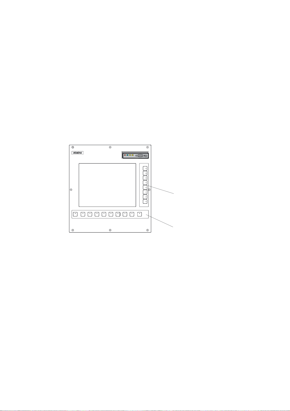
1.1 Control and display elements
Operator control elements
The defined functions are called up via the horizontal and vertical softkeys. For a description,
please refer to this manual:
1
9HUWLFDOVRIWNH\V
Figure 1-1 CNC operator panel
+RUL]RQWDOVRIWNH\V
Turning
Programming and Operating Manual, 11/2012, 6FC5398-1CP10-7BA0
11
Page 12
Description
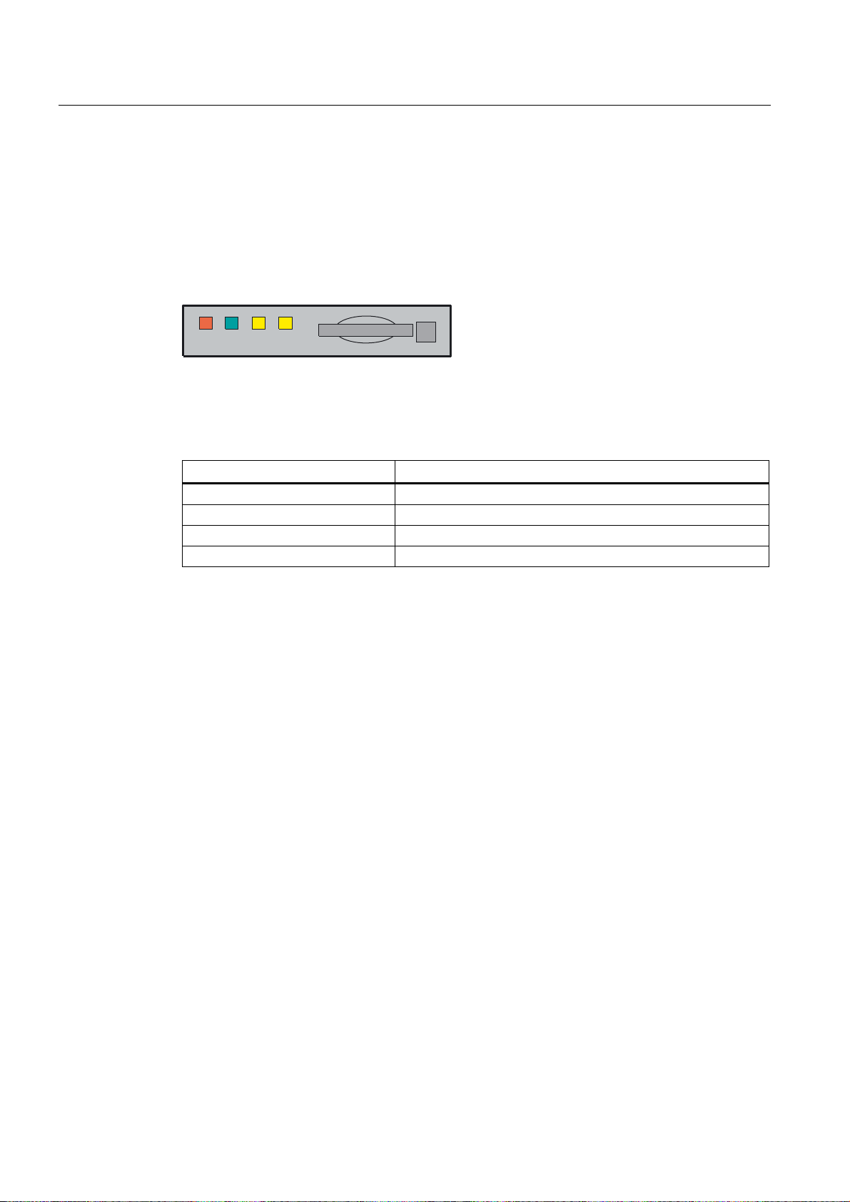
1.2 Error and status displays
1.2 Error and status displays
LED displays on the CNC operator panel (PCU)
The following LEDs are installed on the CNC operator panel.
(55 5'< 1& &)
The individual LEDs and their functions are described in the table below.
Table 1- 1 Status and error displays
LED Significance
ERR (red) Serious error, remedy through power OFF/ON
RDY (green) Ready for operation
NC (yellow) Signoflife monitoring
CF (yellow) Reading from/writing to CF card
References
You can find information on error description in the SINUMERIK 802D sl Diagnostics Manual
Turning
12 Programming and Operating Manual, 11/2012, 6FC5398-1CP10-7BA0
Page 13
Description
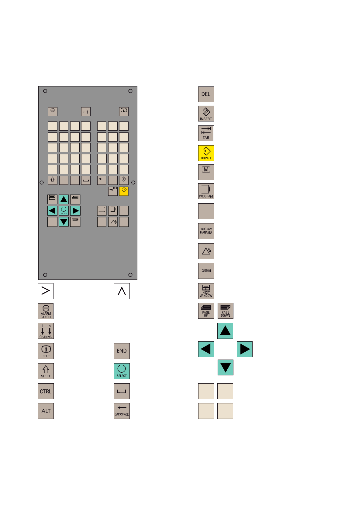
1.3 Key definition of the full CNC keyboard (vertical format)
1.3 Key definition of the full CNC keyboard (vertical format)
&OHDUNH\
$/$50
&$1&(/
2
8
;
0
>
)
6+,)7
1(;7
:,1'2:
(1'
Q
&+$11(/
1
9
<
$
,
-
6
'
&75/
?
(
*
:
=
ಱ
.
7
_
+
$/7
3$*(
83
3$*(
'2:1
3
4
&
@
5
/
"
%
%$&.63$&(
0
326,7,21
3URJUDP
0DQDJHU
#
'(/
7$%
352*5$0
6<67(0
$/$50
+(/3
!
,16(57
,1387
2))6(7
3$5$0
&86720
,QVHUWNH\
7DEXODWRU
(17(5,QSXWNH\
326,7,21RSHUDWLQJDUHDNH\3RVLWLRQ
326,7,21
RSHUDWLQJDUHD
352*5$0RSHUDWLQJDUHDNH\
RSHUDWLQJDUHDSURJUDP
2))6(7
3$5$0
2))6(73$5$0RSHUDWLQJDUHDNH\
3DUDPHWHURSHUDWLQJDUHD
352*5$00$1$*(5RSHUDWLQJDUHDNH\
3URJUDP0DQDJHURSHUDWLQJDUHD
6<67(0
$/$50
6<67(0$/$50RSHUDWLQJDUHDNH\
6\VWHP$ODUPRSHUDWLQJDUHD
&86720RSHUDWLQJDUHDNH\
8VHURSHUDWLQJDUHD
(7&NH\
$FNQRZOHGJHDODUPNH\
1RIXQFWLRQ
,QIRNH\
6KLIWNH\
&RQWURONH\
$/7NH\
5HFDOONH\
6HOHFWLRQNH\WRJJOHNH\
6SDFH
'HOHWHNH\%DFNVSDFH
1RWDVVLJQHG
6FUROONH\V
&XUVRUNH\V
$
:
=
-
$OSKDQXPHULFNH\V
'RXEOHDVVLJQPHQWRQWKHVKLIWOHYHO
1XPHULFNH\V
'RXEOHDVVLJQPHQWRQWKHVKLIWOHYHO
Turning
Programming and Operating Manual, 11/2012, 6FC5398-1CP10-7BA0
13
Page 14

Description
1.3 Key definition of the full CNC keyboard (vertical format)
Hot keys
In the part program editor and in the input fields of the HMI, the following functions can be
carried out with certain shortcut keys on the full CNC keyboard:
Shortcut key Function
<CTRL> and <C> Copy selected text
<CTRL> and <B> Select text
<CTRL> and <X> Cut selected text
<CTRL> and <V> Paste copied text
<CTRL> and <P> Generates a screenshot of the actual screen and
saves the image on CompactFlash Card
(customer CF Card) under "screen802dsl.bmp "
<CTRL> and <R> HMI restart
<CTRL> and <S> Data backup in case of backlight failure
The series start-up archive (Drive/NC/PLC/HMI)
is exported with the most recent data onto the
CompactFlash card with the name
"802Dslibn.arc".
<ALT> and <L> Toggling between only upper case letters and
upper and lower case letters
<ALT> and <H> or <HELP> key Call help system
<ALT> and <S> Switch-in and switch-out the Editor for Asian
characters
Turning
14 Programming and Operating Manual, 11/2012, 6FC5398-1CP10-7BA0
Page 15
Description
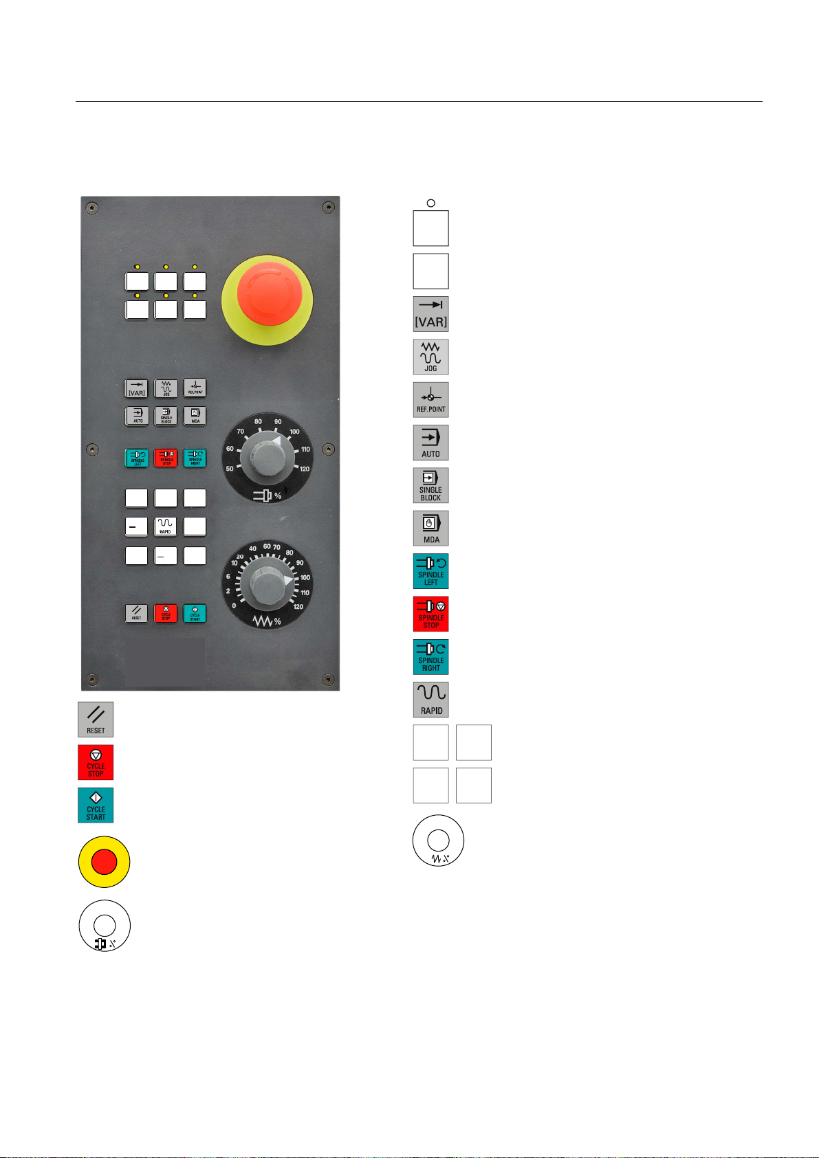
1.4 Key definition of the machine control panel
1.4 Key definition of the machine control panel
8VHUGHILQHGNH\ZLWK/('
8VHUGHILQHGNH\ZLWKRXW/('
,1&5(0(17
,QFUHPHQW
-2*
5()(5(1&(32,17
5HIHUHQFHSRLQW
$8720$7,&
6,1*/(%/2&.
;
6LQJOHEORFN
=
=
;
5(6(7
&<&/(6723
1&6723
&<&/(67$57
1&67$57
(0(5*(1&<2))
;
=
;
=
0$18$/'$7$
0DQXDOLQSXW
63,1'/(67$57&&:
&RXQWHUFORFNZLVH
63,1'/(6723
63,1'/(67$57&:
&ORFNZLVH
5$3,'75$9(56(29(5/$<
5DSLGWUDYHUVHRYHUULGHRYHUOD\
;D[LV
=D[LV
)HHGUDWHRYHUULGH
)HHGUDWHRYHUULGH
6SLQGOH6SHHG2YHUULGH
6SLQGOHRYHUULGH
Turning
Programming and Operating Manual, 11/2012, 6FC5398-1CP10-7BA0
15
Page 16
Description
1.5 Coordinate systems
Note
This documentation assumes an 802D standard machine control panel (MCP). Should you
use a different MCP, the operation may be other than described herein.
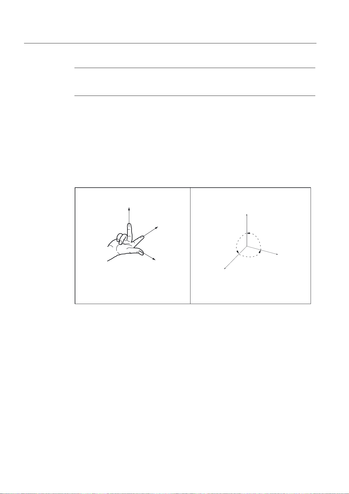
1.5 Coordinate systems
As a rule, a coordinate system is formed from three mutually perpendicular coordinate axes.
The positive directions of the coordinate axes are defined using the so-called "3-finger rule"
of the right hand. The coordinate system is related to the workpiece and programming takes
place independently of whether the tool or the workpiece is being traversed. When
programming, it is always assumed that the tool traverses relative to the coordinate system
of the workpiece, which is intended to be stationary.
=
;
<
=
90°
<
90°
90°
;
Figure 1-2 Determining the axis directions to one another; coordinate system for programming
Machine coordinate system (MCS)
The orientation of the coordinate system relative to the machine depends on the respective
machine type. It can be rotated in different positions.
The directions of the axes follow the "3-finger rule" of the right hand. Seen from in front of the
machine, the middle finger of the right hand points in the opposite direction to the infeed of
the main spindle.
Turning
16 Programming and Operating Manual, 11/2012, 6FC5398-1CP10-7BA0
Page 17
Description
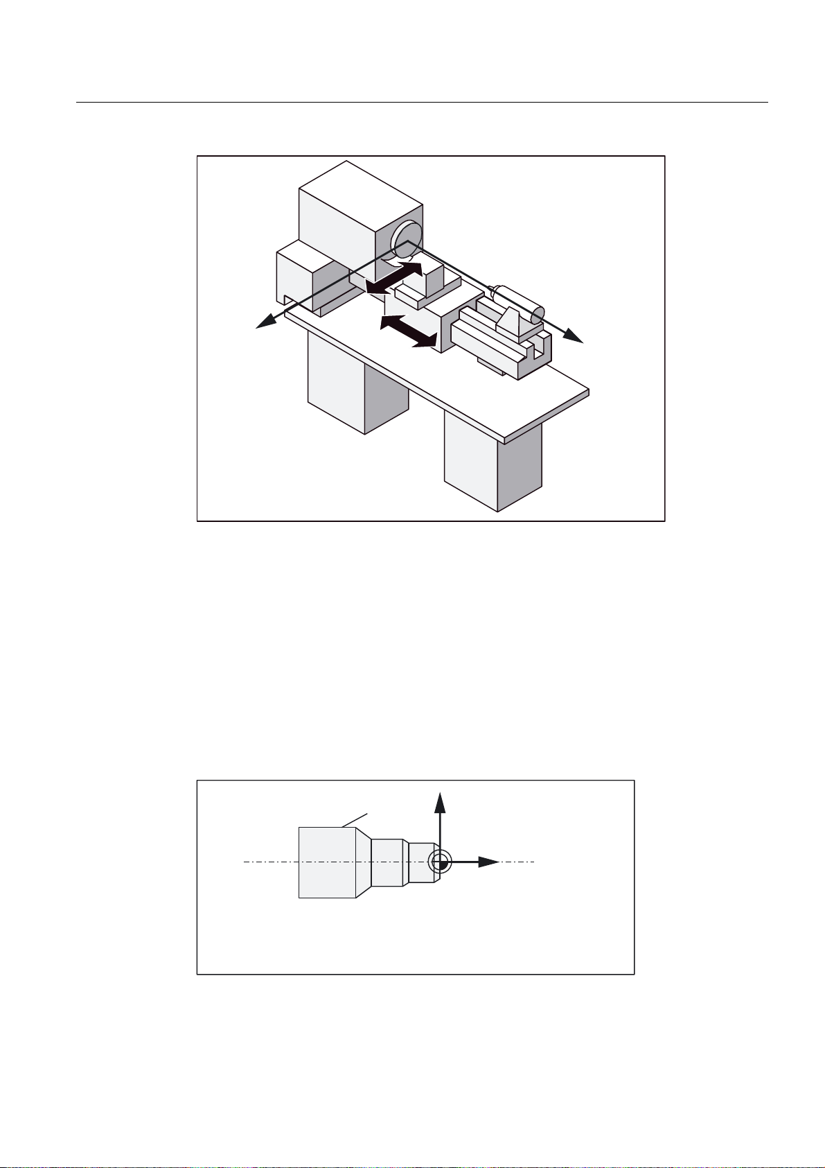
1.5 Coordinate systems
;
Figure 1-3 Machine coordinate axes using the example of a turning machine
The origin of this coordinate system is the machine zero.
This point is only a reference point which is defined by the machine manufacturer. It does not
have to be approachable.
The traversing range of the machine axes can by in the negative range.
Workpiece coordinate system (WCS)
To describe the geometry of a workpiece in the workpiece program, a right-handed, rightangled coordinate system is also used.
The workpiece zero can be freely selected by the programmer in the Z axis. In the X axis, it
lies in the turning center.
=
:RUNSLHFH
: ZRUNSLHFH]HUR
Figure 1-4 Workpiece Coordinate System
Turning
Programming and Operating Manual, 11/2012, 6FC5398-1CP10-7BA0
;
:RUNSLHFH
:
=
:RUNSLHFH
17
Page 18
Description
=
;
:
;
=
0b
1.5 Coordinate systems
Relative coordinate system (REL)
In addition to the machine and workpiece coordinate systems, the control system provides a
relative coordinate system. This coordinate system is used for setting reference points that
can be freely selected and have no influence on the active workpiece coordinate system. All
axis movements are displayed relative to these reference points.
Note
You can activate and display the actual value of the relevant coordinate system by pressing
the vertical softkey "MCS/WCS REL" in the Position operating area.
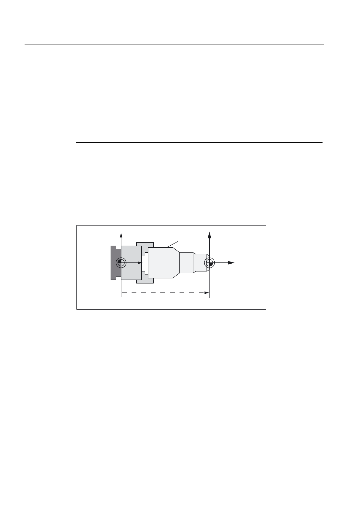
Clamping the workpiece
For machining, the workpiece is clamped on the machine. The workpiece must be aligned
such that the axes of the workpiece coordinate system run in parallel with those of the
machine. Any resulting offset of the machine zero with reference to the workpiece zero is
determined along the Z axis and entered in a data area intended for the settable work offset.
In the NC program, this offset is activated during program execution, e.g. using a
programmed G54.
0DFKLQH
0b
Figure 1-5 Workpiece on the machine
Current workpiece coordinate system
The programmed work offset TRANS can be used to generate an offset with reference to the
workpiece coordinate system resulting in the current workpiece coordinate system resulting
in the current workpiece coordinate system (see section "Programmable work offset:
TRANS").
0DFKLQH
:RUNSLHFH
:RUNSLHFH
:RUNSLHFH
HJ*
Turning
18 Programming and Operating Manual, 11/2012, 6FC5398-1CP10-7BA0
Page 19
Software interface
2.1 Screen layout
6WDWXVDUHD
$SSOLFDWLRQDUHD
7LS
DQGVRIWNH\DUHD
Figure 2-1 Screen layout
2
Status area
The screen is divided into the following main areas:
● Status area
● Application area
● Note and softkey area
Figure 2-2 Status area
Turning
Programming and Operating Manual, 11/2012, 6FC5398-1CP10-7BA0
19
Page 20
Software interface
2.1 Screen layout
Table 2- 1 Explanation of the screen controls in the status area
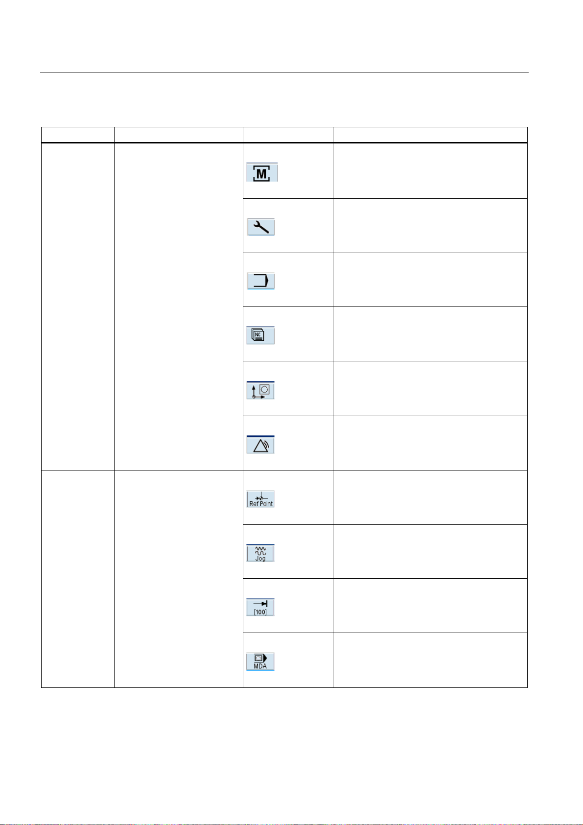
Numbering Display Icon Significance
①
Active operating area
Position (operating area key <POSITION>)
System (operating area key <SYSTEM>)
Program (operating area key <PROGRAM>)
Program Manager (operating area key
<PROGRAM MANAGER>)
Parameter (operating area key <OFFSET
PARAM>)
Alarm (operating area key <ALARM>)
②
Active mode
Approaching a reference point
JOG
JOG INC; 1 INC, 10 INC, 100 INC, 1000 INC,
VAR INC
(incremental evaluation in the JOG mode)
MDA
Turning
20 Programming and Operating Manual, 11/2012, 6FC5398-1CP10-7BA0
Page 21

Software interface
2.1 Screen layout
Numbering Display Icon Significance
AUTOMATIC
③
④
⑤
⑥
⑦
Alarm and message line In addition, the following is displayed:
1. Alarm number with alarm text, or
2. Message text
Selected part program (main program)
Program state
Program control in automatic
mode
Date and time From version 1.4 SP 6 and higher, the date and
RESET Program canceled / default state
RUN Program is running
STOP Program stopped
SKP Skip: Skip block
DRY Dry Run: Dry run feedrate
ROV Rapid Override: Rapid traverse override
M01 Conditional stop
PRT Program test
SBL Single Block: Single block
the time are displayed.
Note and softkey area
Figure 2-3 Note and softkey area
Turning
Programming and Operating Manual, 11/2012, 6FC5398-1CP10-7BA0
21
Page 22
Software interface
2.1 Screen layout
Table 2- 2 Explanation of the screen controls in the note and softkey area
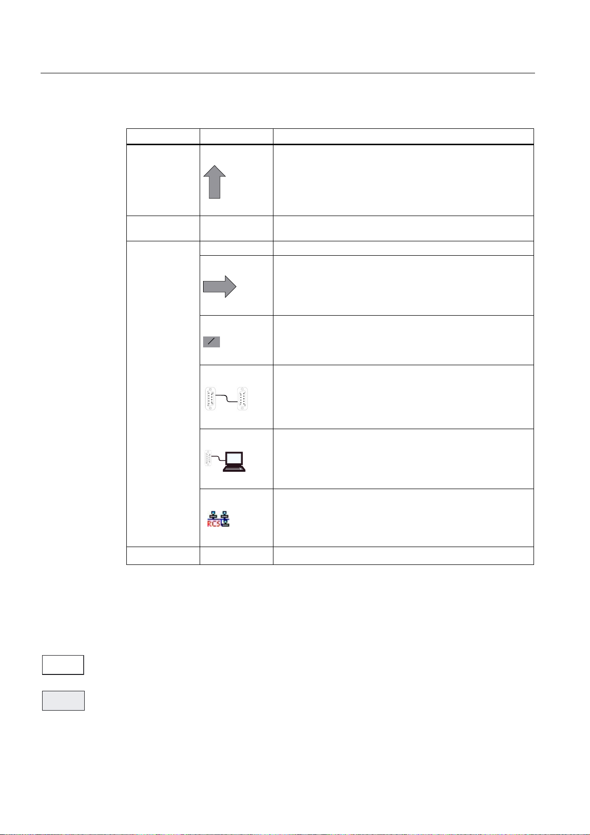
Screen item Display Significance
①
RECALL symbol
Pressing the <RECALL> key lets you return to the higher menu
level.
②
③
Information line
Displays notes and information for the operator and fault states
HMI status information
ETC is possible (pressing this key displays the horizontal
softkey bar providing further functions.)
ಯ/ಯ
Mixed notation active (uppercase/lowercase letters)
RS232 connection active
④
Softkey bar vertical and horizontal
Display of the softkeys in the document
To make the softkeys easier to locate, the horizontal and vertical softkeys are displayed in
different basic colors.
Horizontal softkey
Vertical softkey
Connection to commissioning and diagnostic tools (e.g.
Programming Tool 802) active
RCS network connection active
Turning
22 Programming and Operating Manual, 11/2012, 6FC5398-1CP10-7BA0
Page 23
Software interface
;
2.2 Standard softkeys
2.2 Standard softkeys
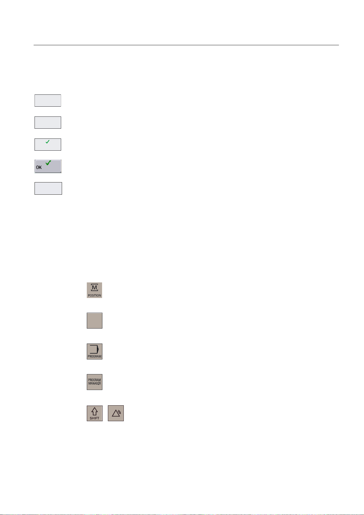
%DFN
Use this softkey to close the screen.
$ERUW
Use this softkey to cancel the input; the window is closed.
$FFHSW
Selecting this softkey will complete your input and start the calculation.
Selecting this softkey will complete your input and accept the values you have entered.
8VHU
IXQFWLRQ
User-specific functions are called in the operating areas <POSITION>, <OFFSET
PARAMETER> and <SYSTEM>. The softkey is only visible if the machine manufacturer
saved special functions.
Refer to the following documentation for softkey activation: Operating Instructions,
SINUMERIK 802D sl Turning, Milling, Grinding, Chapter: Activating "User function" softkey.
2.3 Operating areas
The functions of the control system can be carried out in the following operating areas:
2))6(7
3$5$0
6<67(0
$/$50
POSITION
Machine operation
OFFSET PARAM Entering the compensation values and setting data
PROGRAM
Creation of part programs
PROGRAM
Part program directory
MANAGER
SYSTEM
Diagnostics, commissioning
Turning
Programming and Operating Manual, 11/2012, 6FC5398-1CP10-7BA0
23
Page 24

Software interface
2.3 Operating areas
Protection levels
6<67(0
$/$50
ALARM
Alarm and message lists
CUSTOM
Users can call their own application
To change to another operating area, press the relevant key on the CNC full keyboard (hard
key).
The SINUMERIK 802D sl provides a concept of protection levels for enabling data areas.
The control system is delivered with default passwords for the protection levels 1 to 3.
Protection level 1 Experts password
Protection level 2 Manufacturer password
Protection level 3 User password
These control the various access rigths.
In the menus listed below the input and modification of data depends on the protection level
set:
● Tool offsets
● Work offsets
● Setting data
● RS232 settings
● Program creation / program correction
Turning
24 Programming and Operating Manual, 11/2012, 6FC5398-1CP10-7BA0
Page 25
Software interface
2.4 The help system
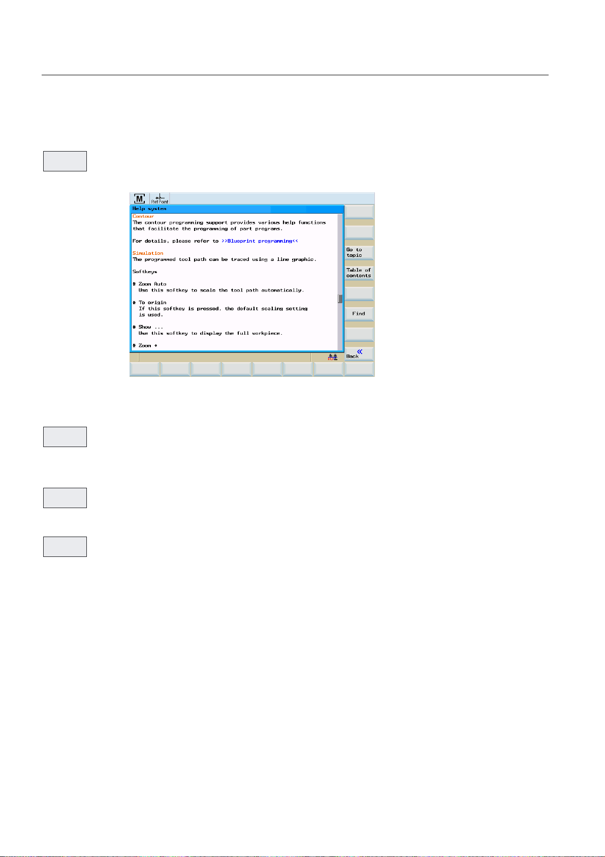
2.4 The help system
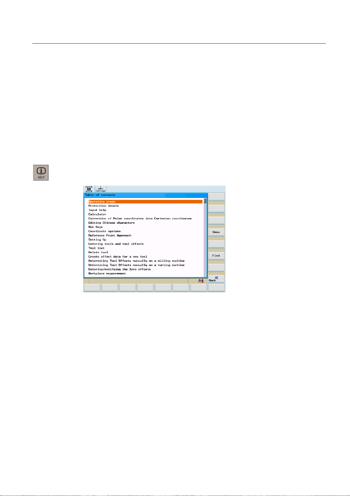
Comprehensive online help is stored in the control system. Some help topics are:
● Product brief of all important operating functions
● Overview and product brief of the NC commands
● Explanation of the drive parameters
● Explanation of the drive alarms
Operating sequence
You can call the help system from any operating area either by pressing the Info key or by
using the key combination <ALT+H>.
Figure 2-4 Help system: Table of contents
Turning
Programming and Operating Manual, 11/2012, 6FC5398-1CP10-7BA0
25
Page 26
Software interface
2.4 The help system
Softkeys
6KRZ
*RWR
7RSLF
This function opens the selected topic.
Figure 2-5 Help system: Description of the topic
Use this function to select cross references. A cross reference is marked by the characters
">>....<<". This softkey is only displayed if a cross reference is displayed in the application
area.
%DFNWR
7RSLF
If you select a cross-reference, the "Back to topic" softkey will also be displayed. Select this
function to go back to the previous screen.
)LQG
Use this function to search for a term in the table of contents. Type the term you are looking
for and start the search process.
Help in the "Program editor" area
The help system offers an explanation for each NC operation. To display the infotext directly,
position the cursor after the appropriate operation and press the Info key. The NC instruction
must be written using uppercase letters.
Turning
26 Programming and Operating Manual, 11/2012, 6FC5398-1CP10-7BA0
Page 27
Turning On, Reference Point Approach
3.1 Switching on, reference point approach
Operating sequence
Note
When turning on the SINUMERIK 802D sl and the machine, please also observe the
machine documentation, since turning on and reference point approach are machinedependent functions.
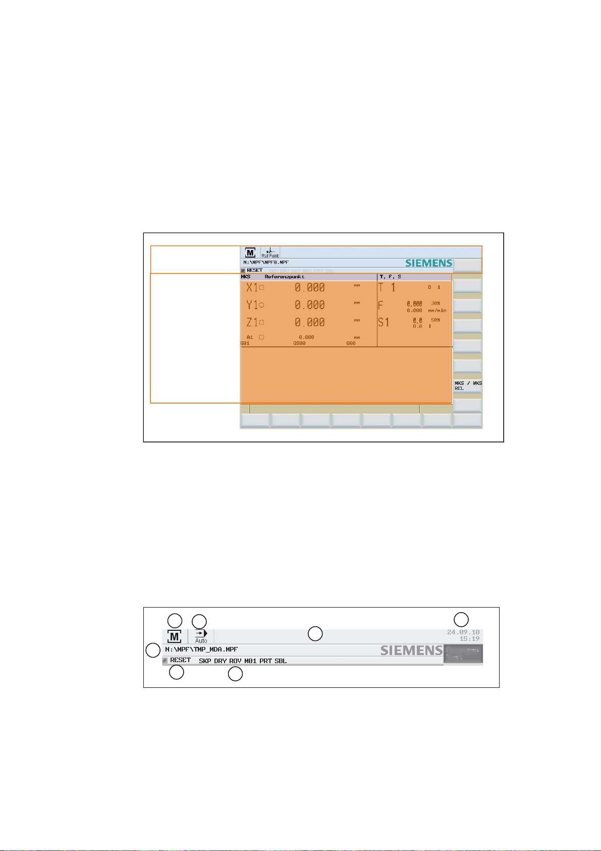
First, switch on the power supply for the CNC and the machine.
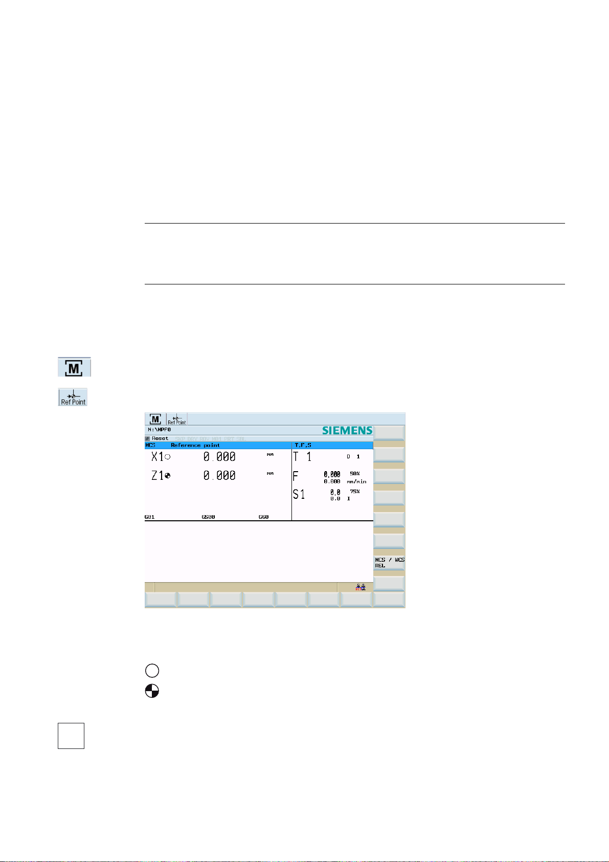
After the control system has booted, you are in the "Position" operating area, in the
"Reference point approach" mode.
The 'Reference point' window is active.
3
Figure 3-1 Reference-point approach start screen
The "Reference point" window displays whether the axes are referenced.
$[LVPXVWEHUHIHUHQFHG
$[LVLVUHIHUHQFHGV\QFKURQL]HG
;
Turning
Programming and Operating Manual, 11/2012, 6FC5398-1CP10-7BA0
Press the arrow keys.
27
Page 28

Turning On, Reference Point Approach
3.1 Switching on, reference point approach
=
If you select the wrong approach direction, no motion is carried out.
One after the other, move each axis to the reference point.
You can exit the function by selecting another operating mode (MDA, AUTOMATIC or JOG).
To access the functions described below, you need to select <JOG> mode.
Turning
28 Programming and Operating Manual, 11/2012, 6FC5398-1CP10-7BA0
Page 29

Set up
Preliminary remarks
Before you can work with the CNC, set up the machine, the tools, etc. as follows:
● Enter the tools and the tool offsets.
● Enter/modify the work offset
● Enter the setting data.
4.1 Entering tools and tool offsets
4.1.1 Entering tools and tool offsets
Functionality
4
The tool offsets consist of several data describing the geometry, the wear and the tool type.
Each tool contains a defined number of cutting edge parameters dependent on the particular
tool type. Tools are identified by a number (T number).
See also Chapter "
Operating sequences
2))6(7
3$5$0
7RRO
OLVW
Press the <OFFSET PARAM> key.
The function opens the "Tool list" window with the tool offset data. The window contains a list
of the tools that have been created. Use the cursor keys and the Page Up / Page Down keys
to navigate in this list.
Position the cursor bar on the input field to be modified and enter the value(s).
Confirm with <Input> or by moving the cursor.
Tool and tool compensation (Page 272)"
Turning
Programming and Operating Manual, 11/2012, 6FC5398-1CP10-7BA0
29
Page 30
Set up
4.1 Entering tools and tool offsets
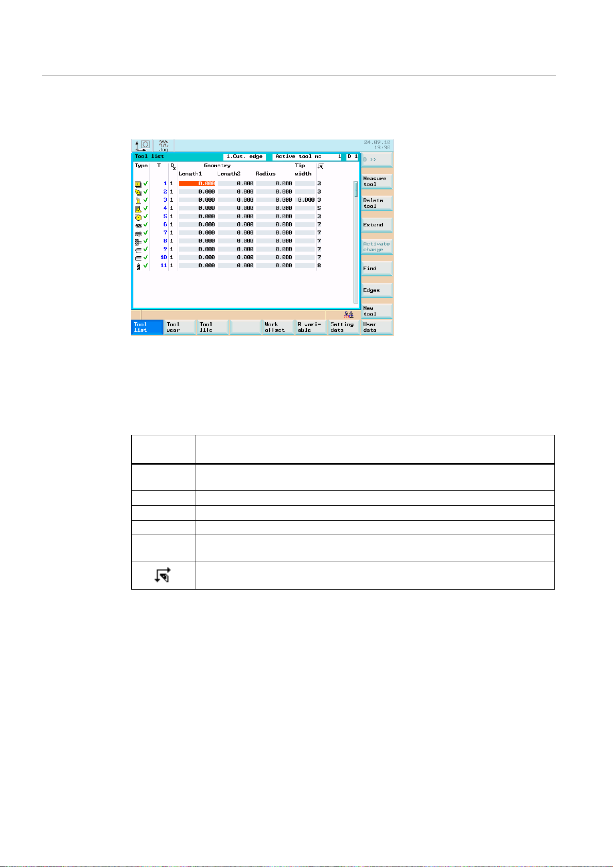
Standard tool list
Figure 4-1 Tool list
The tool nose radius compensation parameters of the T tools are shown in the tool list.
Contents of the tool list:
Table 4- 1 Tool list
Symbol/
Header
Type Cutting edge type of the tool and tool monitoring symbols (refer to the Chapter "Tool
T Tool number
D∑ Number of tool cutting edges
Geometry Tool geometry
Cutting tip
width
Content
monitoring")
Tip width of the cutting edge
Cutting edge position of the cutting edge
The following is displayed in the "tool list" line:
● The particular cutting edge number for all tools. Can be selected using softkey "D >>".
● The tool number and cutting edge number currently selected at the machine (e.g. 2, D 1)
Turning
30 Programming and Operating Manual, 11/2012, 6FC5398-1CP10-7BA0
Page 31

Set up
4.1 Entering tools and tool offsets
Tool wear, standard
7RRO
ZHDU
The function opens the "tool wear" window. The window contains a list of the tools that have
been created and the wear data of the currently selected cutting edge. Use the cursor keys
and the Page Up / Page Down keys to navigate in this list.
Figure 4-2 Tool wear, standard
User-defined tool list
After having activated display MD394 DISPLAY_TOOL_LIST_SISTER_TOOL with "1", you
may define the following additional cutting edge parameters for the tool:
● Sister tool
● Wear limit
Note
The input values from the user fields "Sister tool" and "Wear limit" from the "Tool list" tab
are stored in the tool variables $TC_DP24 (wear limit) and $TC_DP25 (sister tool).
Turning
Programming and Operating Manual, 11/2012, 6FC5398-1CP10-7BA0
31
Page 32

Set up
4.1 Entering tools and tool offsets
Figure 4-3 User-defined tool list
([WHQGHG
Softkeys
0HDVXUH
WRRO
0HDVXULQJ
0DQXDO
0HDVXULQJ
$XWR
&DOLEUDWH
SUREH
Deleting a
tool
([WHQGHG
For special tools, use the "extended" softkey function, which provides a complete cutting
edge parameter list.
Use this softkey to determine the tool offset data (only effective in the JOG mode!).
Use this softkey to determine the tool offset data manually.
Use this softkey to determine the tool offset data semi-automatically (only applies in
conjunction with a probe).
Calibrating the measuring probe.
The tool is deleted and removed from the tool list.
A complete list of the cutting edge parameters is displayed using the "Extended" function.
Turning
32 Programming and Operating Manual, 11/2012, 6FC5398-1CP10-7BA0
Page 33

Set up
4.1 Entering tools and tool offsets
Figure 4-4 Input screen for special tool
For the meanings of the cutting edge parameters, please refer to the Section
"Programming".
&XWWLQJ
HGJHV
Opens a lower-level menu bar offering all functions required to create and display further
edges.
D >>
1HZFXWWLQJ
HGJH
5HVHWFXWWLQJ
HGJH
'HOHWH
FXWWLQJHGJH
&KDQJH
DFWLYH
&KDQJH
W\SH
6HDUFK
Use this softkey to select the next higher edge number.
Use this softkey to create a new edge.
Use this softkey to reset all offset values of the edge to zero.
Cutting edge is deleted.
Modified values are activated.
This function is intended to change the tool type. Select the tool type using the appropriate
softkey.
Find tool number:
Type the number of the tool you are looking for and use the "OK" softkey to start the search.
If the tool you are looking for exists, the cursor is positioned on the appropriate line.
1HZWRRO
Turning
Programming and Operating Manual, 11/2012, 6FC5398-1CP10-7BA0
Use this softkey to create tool offset data for a new tool.
33
Page 34

Set up
4.1 Entering tools and tool offsets
4.1.2 Create new tool
Operating sequence
1HZWRRO
This function offers another two softkey functions to select the tool type "Turning tool", "Drill"
or "Milling tool". After selecting the tool type, enter the desired "Tool number" (3 digits max.)
in the input field and select the "Cutting edge position" and the "Type".
Figure 4-5 "New tool" window
Figure 4-6 Input of the tool number and cutting edge position of a turning tool
Turning
34 Programming and Operating Manual, 11/2012, 6FC5398-1CP10-7BA0
Page 35

Set up
4.1 Entering tools and tool offsets
Note
The coordinate system of tools for turning depends on the following display machine data:
MD290 CTM_POS_COORDINATE_SYSTEM
= 0 -> position of the tool after the turning center
= 2 -> position of the tool before the turning center
For drills and milling tools, the cutting edge position that corresponds to the machining
direction is selected.
Figure 4-7 Entering a tool number and cutting edge position for a drill
Figure 4-8 Input of the tool number and cutting edge position of a milling tool
Turning
Programming and Operating Manual, 11/2012, 6FC5398-1CP10-7BA0
35
Page 36

Set up
4.1 Entering tools and tool offsets
2.
list.
4.1.3 Determining the tool offsets (manually)
Select "OK" to confirm your input. A data record loaded with zero will be included in the tool
Functionality
7RRO
PHDVXUHPHQW
Note
Assignment of Length 1 or Length 2 to the axis is dependent on the tool type (turning tool,
drill) (see the following figures).
For the turning tool, the reference point for the X axis is a diameter dimension!
Note
The axis coordinates used for the calculation refer to the machine coordinate system.
This function can be used to determine the unknown geometry of a tool T.
Using the actual position of the point F (machine coordinate) and the reference point, the
control system can calculate the offset value assigned to length 1 or length 2 for the axis.
) 7RROKROGHUUHIHUHQFHSRLQW
00DFKLQH]HURSRLQW
::RUNSLHFH]HUR
7KHRIIVHWYDOXHLQWKH;D[LV
LVDGLDPHWHUYDOXH
;
PDFKLQH
0
;DFWXDOSRVLWLRQ
:RUNSLHFH
HJ*
'LDPHWHU
:
)
=DFWXDOSRVLWLRQ
=
PDFKLQH
Figure 4-9 Determining the length offsets using the example of a turning tool
Turning
36 Programming and Operating Manual, 11/2012, 6FC5398-1CP10-7BA0
Page 37

Set up
4.1 Entering tools and tool offsets
) 7RROKROGHU UHIHUHQFH SRLQW
00DFKLQH]HURSRLQW
::RUNSLHFH]HUR
;
PDFKLQH
:RUNSLHFH
=DFWXDOSRVLWLRQ
Prerequisite
0
HJ*
:
)
=
PDFKLQH
Figure 4-10 Determining the length offsets using the example of a drill: Length 1 / Z axis
Note
The figure "Determining the length offsets using the example of a drill: Length 1/Z axis" will
only apply, if setting data SD42950 $SC_TOOL_LENGTH_TYPE and
SD42940 $SC_TOOL_LENGTH_CONST are equal to "0". Otherwise Length 2 will apply for
the drilling and the milling tool.
A tool must be loaded to use the "Measure tool" function.
Display machine data
The following display machine data define the display in the "Tool measurement manual"
window:
● MD290 CTM_POS_COORDINATE_SYSTEM
– = 0 -> position of the tool after the turning center
– = 2 -> position of the tool before the turning center
● MD361 USER_MEAS_TOOL_CHANGE
– = 0 -> not possible to edit the "T" and "D" fields
The "T" tool currently selected at the machine and its tool offset "D" are manually
measured.
– = 1 -> it is possible to edit the "T" and "D" fields
Tools, that have not been selected at the machine can also be manually measured.
Turning
Programming and Operating Manual, 11/2012, 6FC5398-1CP10-7BA0
37
Page 38

Set up
4.1 Entering tools and tool offsets
7RRO
PHDVXUHPHQW
0HDVXULQJ
0DQXDO
Figure 4-11 Selecting manual or semiautomatic measuring
The "Tool measurement manual" window is opened with the default setting "Measure length
1 in the X axis".
Figure 4-12 "Tool measurement manual" window, Length1 (L)
Workpiece parameters and operating sequence to manually measure the tool "Length1"
Enter the following workpiece parameters for the particular length calculation of the tool:
● The thickness of a spacer can be taken into account in the calculation in the distance field
(a).
● Enter the workpiece diameter in the "Ø" field.
Turning
38 Programming and Operating Manual, 11/2012, 6FC5398-1CP10-7BA0
Page 39

Set up
4.1 Entering tools and tool offsets
6DYH
SRVLWLRQ
● With the cutting edge of the tool, move in the X axis up to the edge of the clamped
workpiece or to the spacer. Press "Save position".
The actual position that has been approached is taken into account in the control.
6HW
OHQJWK
● Press "Set Length1".
The length value is calculated and saved in the tool offset data.
Workpiece parameters and operating sequence to manually measure the tool "Length2"
/HQJWK
To determine length 2, press "Length2".
Figure 4-13 "Tool measurement manual" window, for Length2 (L)
Enter the following workpiece parameters for the particular length calculation of the tool:
● The thickness of a spacer can be taken into account in the calculation in the distance field
(a).
● Enter the workpiece edge in the field "Z0", if "ABS" was pre-selected in the adjacent
toggle field.
Note
As the known machine coordinate you may also use the work offset already determined
(e.g G54 value). This should be selected in the toggle field for the reference point.
Turning
Programming and Operating Manual, 11/2012, 6FC5398-1CP10-7BA0
39
Page 40

Set up
4.1 Entering tools and tool offsets
Workpiece parameters and operating sequence to manually measure a drill "Length1"
Figure 4-14 Tool measurement window, length1 (L) for a drill
Enter the following workpiece parameters for the particular length calculation of the tool:
● The thickness of a spacer can be taken into account in the calculation in the distance field
(a).
● Enter the workpiece edge in the field "Z0", if "ABS" was pre-selected in the adjacent
toggle field.
Note
As the known machine coordinate you may also use the work offset already determined
(e.g G54 value). This should be selected in the toggle field for the reference point.
With the cutting edge of the tool, move in the Z axis up to the edge of the clamped
workpiece or to the spacer. Then press "Set Length1", the length value is calculated and
saved in the tool offset data.
Turning
40 Programming and Operating Manual, 11/2012, 6FC5398-1CP10-7BA0
Page 41

Set up
4.1 Entering tools and tool offsets
Workpiece parameters and operating sequence to manually measure a driven milling tool "Length2"
Figure 4-15 Manually measuring a driven milling tool
6DYH
SRVLWLRQ
6HW
OHQJWK
Enter the following workpiece parameters for the particular length calculation of the tool:
● The thickness of a spacer can be taken into account in the calculation in the distance field
(a).
● Enter the workpiece diameter in the "Ø" field.
● Enter the milling tool radius in the "Radius" field.
● With the cutting edge of the tool, move in the X axis up to the edge of the clamped
workpiece or to the spacer. Press "Save position".
The actual position that has been approached is taken into account in the control.
● Press "Set Length2".
The length value is calculated and saved in the tool offset data.
Note
The effect of the softkey is determined by display machine data
MD373 MEAS_SAVE_POS_LENGTH2.
= 0 -> the softkey is only active when measuring length 1
= 1 -> the softkey is always active
Turning
Programming and Operating Manual, 11/2012, 6FC5398-1CP10-7BA0
41
Page 42

Set up
4.1 Entering tools and tool offsets
4.1.4 Determining tool offsets using a probe (auto)
Operating sequence
7RRO
PHDVXUHPHQW
Press the "Measure tool" softkey.
0HDVXULQJ
$XWR
The "Measure tool automatically" window is opened.
Figure 4-16 "Tool measurement auto" window for Length1 (L)
Figure 4-17 "Tool measurement auto" window, Length2 (L)
Turning
42 Programming and Operating Manual, 11/2012, 6FC5398-1CP10-7BA0
Page 43

Set up
4.1 Entering tools and tool offsets
Display machine data
The following display machine data defines the display in the "Tool measurement auto"
window:
● MD290 CTM_POS_COORDINATE_SYSTEM
– = 0 -> position of the tool after the turning center (refer to the diagrams above)
– = 2 -> position of the tool before the turning center
"Tool measurement auto" screen form
This screen form allows you to enter the tool number and tool offset number.
After the screen form has been opened, the input fields are filled with the data of the tool
currently working.
The tool can be either
● the currently active tool of the NC (loaded via a part program) or
● a tool loaded by the PLC.
If the tool was loaded by the PLC, the tool number in the input screen can be different than
that in the T,F,S window.
If you change the tool number, no automatic tool change will be performed using this
function. However, the measurement results are assigned to the entered tool.
Measuring process
The measuring probe is approached using traversing keys.
After the "Probe tripped" symbol has appeared, release the traversing key and wait until the
measuring process is completed.
During the automatic measurement, a dial gauge is displayed, which symbolizes the
measuring process currently active.
Note
To create the measuring program, the safety clearance parameters from the "Settings"
screen form and the feedrate from the "Probe data" screen form are used (see chapter
"Probe settings").
If several axes are moved simultaneously, no offset data can be calculated.
Turning
Programming and Operating Manual, 11/2012, 6FC5398-1CP10-7BA0
43
Page 44

Set up
4.1 Entering tools and tool offsets
Procedure for "Probe tripped"
A solid circle on the screen indicates that the measuring probe has been tripped.
Release the axis direction key after tripping of the probe.
After release of the axis direction key, the control automatically creates an internal
measuring program in the program memory and starts it.
This measuring program causes the probe to be approached max. three times in order to
deliver measured values to the control.
If no measured value is transferred to the control after the third approach of the probe, a
message will be displayed informing the operator that no measured values could be
collected.
All axes involved in the measuring process must be approached this way.
4.1.5 Determining the tool offsets using optical measuring instruments
Figure 4-18 Measuring using an optical measuring instrument (for the T and D input fields, please
refer to "Measuring using a probe")
Measuring process
For measuring, traverse the tool until its tip appears in the crosshair. With a milling tool, use
the highest point of the cutting edge to determine the tool length.
Then press the "Set length" softkey to calculate the offset values.
Turning
44 Programming and Operating Manual, 11/2012, 6FC5398-1CP10-7BA0
Page 45

Set up
4.1 Entering tools and tool offsets
4.1.6 Probe settings
6HWWLQJV
3UREHGDWD
Select the "Settings" softkey.
The screen form below is used to store the coordinates of the probe and to set the axis
feedrate for the automatic measuring process.
All position values refer to the machine coordinate system.
Figure 4-19 "Probe data" input screen
Probe calibration
&DOLEUDWH
SUREH
Parameter Significance
Absolute position P1 Absolute position of the probe in Z direction
Absolute position P2 Absolute position of the probe in X+ direction
Absolute position P3 Absolute position of the probe in Z+ direction
Absolute position P4 Absolute position of the probe in X- direction
Feedrate Feedrate with which the tool approaches the probe
The probe can be calibrated either in the "Settings" menu or in the "Measure tool" menu. The
four points of the probe must be approached.
For calibration, use a tool of the type 500 with tool tip position 3 or 4.
The offset parameters required to determine the four probe positions can be written to the
data records of two cutting edges.
Turning
Programming and Operating Manual, 11/2012, 6FC5398-1CP10-7BA0
45
Page 46

Set up
4.1 Entering tools and tool offsets
Figure 4-20 Calibrating the probe
After the screen form has appeared, an animation signaling the step to be executed is
displayed next to the current positions of the probe. This point must be approached with the
appropriate axis.
After the "Probe tripped" symbol has appeared, release the traversing key and wait until the
measuring process is completed.
During the automatic measurement, a dial gauge is displayed, which symbolizes the
measuring process currently active.
The positions delivered by the measuring program serve to calculate the real probe position.
The measuring function can be quit without approaching all positions. The points already
sensed are stored.
Note
To create the measuring program, the "Safety clearance" parameters from the "Settings"
screen form and the feedrate from the "Probe data" screen form are used.
If several axes are moved simultaneously, no offset data can be calculated.
Use the "Next Step" function to skip a point if this is not needed for measuring.
Turning
46 Programming and Operating Manual, 11/2012, 6FC5398-1CP10-7BA0
Page 47

Set up
4.2 Tool monitoring
4.2 Tool monitoring
Functionality
This function is available for SINUMERIK 802D sl plus and 802D sl pro.
The following types of active cutting edge monitoring for the active tool are possible:
● Monitoring the service life
By activating service life monitoring, the service life during the action time of the tool (G1,
G2, G3) is monitored.
● Monitoring of the workpiece count
By activating workpiece count monitoring, the workpiece count is monitored via the
program command SETPIECE( ) at the end of the part program.
See also the chapter "Language commands for tool monitoring".
Note
Set the following machine data to enable the "tool monitoring" function:
• General machine data
MD18080 $MN_MM_TOOL_MANAGEMENT_MASK bit 1 = 1: Memory for the monitoring
data (WZMO) is provided.
• Channel machine data
MD20310 $MC_TOOL_MANAGEMENT_MASK bit 1 = 1: Tool management monitoring
function is active.
After the machine data were changed, proceed as follows at the control:
1. Backup the commissioning archive data (Drive/NC/PLC/HMI).
2. Download the commissioning archive data that was backed up.
Operating sequence
2))6(7
3$5$0
7RRO
PRQLWRULQJ
Monitoring is carried out in the <OFFSET PARAM> > "Tool monitoring" operating area.
Turning
Programming and Operating Manual, 11/2012, 6FC5398-1CP10-7BA0
47
Page 48

Set up
4.2 Tool monitoring
Figure 4-21 Tool monitoring
Each monitoring type is displayed in four columns.
● Setpoint
● Prewarning limit
● Residual value
● active
5HVHW
PRQLWRULQJ
Using the checkbox element in the fourth column, the monitoring type can be switched to
active/inactive.
The symbols in the "Type" column have the following meaning:
Prewarning limit reached
The tool is released
Tool disabled
Monitoring for the selected tool is reset.
Figure 4-22 Reset monitoring
Turning
48 Programming and Operating Manual, 11/2012, 6FC5398-1CP10-7BA0
Page 49

Set up
4.3 Entering / modifying a work offset
4.3 Entering / modifying a work offset
Functionality
After the reference point approach, the actual-value memory and thus also the actual-value
display are referred to the machine zero point. A machining program, however, is always
referred to the workpiece zero. This offset must be entered as the work offset.
Operating sequences
2))6(7
3$5$0
:RUN
RIIVHW
Press the <OFFSET PARAM> key.
Use <OFFSET PARAM> and "Work offset" to select the work offset.
An overview of all settable work offsets will appear on the screen. The screen form
additionally contains the values of the basic offset of the programmed work offset and the
active scaling factors, the "Mirroring active" status display and the total of all active work
offsets.
Figure 4-23 The "Work offset" window
● Position the cursor bar on the input field to be changed
● Enter the value(s).
&KDQJH
DFWLYH
Turning
Programming and Operating Manual, 11/2012, 6FC5398-1CP10-7BA0
The change becomes immediately effective in the NC program.
49
Page 50

Set up
4.3 Entering / modifying a work offset
4.3.1 Determining the work offset
Prerequisite
You have selected the window with the relevant work offset (e.g. G54) and the axis you want
to determine for the offset.
) 7RROKROGHUUHIHUHQFHSRLQW
00DFKLQH]HURSRLQW
::RUNSLHFH]HUR
)
;
PDFKLQH
0
:RUNSLHFH
=DFWXDOSRVLWLRQ
:
=
PDFKLQH
Procedure
0HDVXUH
ZRUNSLHFH
:RUNRIIVHW= "
/HQJWK
Figure 4-24 Determining the work offset Z axis
Press the "Measure workpiece" softkey. The control system will switch to the "Position"
operating area and will open the dialog box for measuring the work offsets. The selected axis
is displayed as a softkey with a blue background.
Then scratch the workpiece with the tool tip.
Figure 4-25 Determining the work offset in X
Turning
50 Programming and Operating Manual, 11/2012, 6FC5398-1CP10-7BA0
Page 51

Set up
4.4 Program setting data
Figure 4-26 Determining the work offset in Z
6HWZRUN
RIIVHW
The softkey calculates the offset and displays the result in the offset field.
4.4 Program setting data
Functionality
The setting data are used to define the settings for the operating states. These can be
changed as necessary.
Operating sequence
2))6(7
3$5$0
6HWWLQJ
GDWD
You are now in the <OFFSET PARAM> operating area.
Press the "Setting data" softkey. The start screen "Setting data" is opened. Other softkey
functions are available here with which you can set various control system options.
Turning
Programming and Operating Manual, 11/2012, 6FC5398-1CP10-7BA0
51
Page 52

Set up
4.4 Program setting data
Figure 4-27 Setting data start screen
● JOG feedrate
Feedrate value in JOG mode
If the feedrate value is zero, the control system will use the value stored in the machine
data.
● Spindle
Spindle speed
● Minimum / maximum
A limitation of the spindle speed in the "Max." (G26) / "Min." (G25) fields can only be
performed within the limit values defined in the machine data.
● Limitation using G96
Programmable upper speed limitation (LIMS) at constant cutting rate (G96).
● Dry run feed (DRY)
The feedrate which can be entered here will be used instead of the programmed feedrate
in the AUTOMATIC mode if the "Dry run feed" function is selected.
● Starting angle for thread (SF)
For thread cutting, a start position for the spindle is displayed as the start angle. A
multiple thread can be cut by changing the angle when the thread cutting operation is
repeated.
Place the cursor bar on the input field to be modified and enter the value.
Either press the <Input> key or move the cursor to confirm.
Turning
52 Programming and Operating Manual, 11/2012, 6FC5398-1CP10-7BA0
Page 53

Set up
4.4 Program setting data
Softkeys
/LPLW
ZRUNLQJDUHD
The working area limitation is active with geometry and additional axes. If you want to use a
working area limitation, its values can be entered in this dialog box. Selecting the "Set active"
softkey enables/disables the values for the axis highlighted by the cursor.
7LPHV
0XOWLSOLHU
Figure 4-28 Working area limitation
Times Counters
Figure 4-29 Times, Counters
Meaning:
● Total parts: Total number of workpieces produced (total actual)
● Parts requested: Number of workpieces required (workpiece setpoint)
Turning
Programming and Operating Manual, 11/2012, 6FC5398-1CP10-7BA0
53
Page 54

Set up
4.4 Program setting data
● Number of parts: This counter registers the number of all workpieces produced since the
starting time.
Note
The counter functionality is set using the following channel-specific machine data:
• MD27880 $MC_PART_COUNTER, the workpiece counter is activated
• MD27882 $MC_PART_COUNTER_MCODE[0-2], workpiece counting with user
defined M command
● Total runtime: Total runtime of NC programs in AUTOMATIC mode
In the AUTOMATIC mode, the runtimes of all programs between NC START and end of
program / RESET are summed up. The timer is zeroed with each power-up of the control
system.
● Program runtime Active tool operating times
The runtime between NC Start and End of program / Reset is measured in the selected
NC program. The timer is reset with the start of a new NC program.
● Feedrate runtime
0LVF
The runtime of the path axes is measured in all NC programs between NC START and
end of program / RESET without rapid traverse active and with the tool active. The
measurement is interrupted when a dwell time is active.
The timer is automatically reset to zero in the case of a "Control power-up with default
values".
Use this function to display all setting data for the control system in the form of a list. The
setting data are divided up into general, axis-specific and channel-specific data.
They can be selected using the following softkey functions:
● "General"
● "Axis-spec."
● "Channel-spec."
Figure 4-30 General setting data
Turning
54 Programming and Operating Manual, 11/2012, 6FC5398-1CP10-7BA0
Page 55

Set up
4.5 R parameters - "Offset/Parameter"operating area
4.5 R parameters - "Offset/Parameter"operating area
Functionality
In the "R parameters" start screen, any R parameters that exist within the control system are
listed. These global parameters can be set or queried by the programmer of the part
program for any purpose in the program and can be changed as required.
Operating sequence
2))6(7
3$5$0
5SDUD
PHWHUV
These can be found in the <OFFSET PARAM> operating area.
Press the <R variable> softkey. The "R variables" start screen appears.
Figure 4-31 "R parameters" start screen
Place the cursor bar on the input field to be modified and enter the values.
Either press the <Input> key or move the cursor to confirm the entry.
)LQG
Searching for R variables
Turning
Programming and Operating Manual, 11/2012, 6FC5398-1CP10-7BA0
55
Page 56

Set up
4.5 R parameters - "Offset/Parameter"operating area
Turning
56 Programming and Operating Manual, 11/2012, 6FC5398-1CP10-7BA0
Page 57

Manually Controlled Mode
5.1 Manually Controlled Mode
The manually controlled mode is possible in JOG and MDA modes.
6HW
EDVH
[
]
$GGLWLRQDO
D[HV
6HWUHO
'HOHWH
EDVH:2
$OOWR
]HUR
%DFN
0HDVXUHPHQW
:RUNSLHFH
:RUN
RIIVHW
[
]
6HWZRUN
RIIVHW
%DFN
0HDVXUHPHQW
7RRO
0HDVXUHPHQW
0DQXDO
0HDVXUHPHQW
$XWR
&DOLEUDWH
SUREH
%DFN
6HWWLQJV
3UREHGDWD
6ZLWFKHV
PP!LQFK
%DFN
5
Figure 5-1 Menu tree JOG, "Position" operating area
Turning
Programming and Operating Manual, 11/2012, 6FC5398-1CP10-7BA0
57
Page 58

Manually Controlled Mode
5.2 JOG mode - "Position" operating area
6HW
EDVLV
[
]
$GGLWLRQDO
D[HV
6HWUHO
'HOHWHEDVLV
:2
$OORQ
=HUR
%DFN
3URJUDP
FRQWURO
3URJUDP
7HVWLQJ
7HVWUXQ
)HHGUDWH
&RQGLWLRQDO
VWRS
+LGH
6LQJOH
EORFNILQH
529
HIIHFWLYH
%DFN
7HDFK,Q
7HFKQ
GDWD
5DSLG
WUDYHUVH
/LQHDU
&LUFXODU
(QG
%ORFN
7HDFK,Q
2II
Figure 5-2 Menu tree MDA, "Position" operating area
)DFH
PDFKLQ
3HULSKHUDO
VXUIDFH
$ERUW
2.
6LPXOW
UHFRUG
=RRP
$XWR
=RRP
=RRP
6KRZ
'LVSO
DUHDV
'HOHWH
VFUHHQ
&XUVRU
%DFN
6HWWLQJV
3UREHGDWD
6ZLWFK
PP!LQFK
%DFN
5.2 JOG mode - "Position" operating area
Operating sequences
Use the <JOG> key on the machine control panel to select the Jog mode.
;
=
To traverse the axes, press the appropriate key of the X or Z axis.
The axes will traverse continuously at the velocity stored in the setting data until the key is
released. If the value of the setting data is zero, the value stored in the machine data is
used.
If necessary set the velocity using the override switch.
When you additionally press the <Rapid traverse override> key, the selected axis will be
traversed at rapid traverse speed until both keys are released.
Turning
58 Programming and Operating Manual, 11/2012, 6FC5398-1CP10-7BA0
Page 59

Manually Controlled Mode
5.2 JOG mode - "Position" operating area
In the <Increment> mode, you can traverse by adjustable increments using the same
operating sequence. The set number of increments is displayed in the status area. To
deselect, press <JOG> again.
The JOG start screen displays the position, feedrate and spindle values, as well as the
current tool.
Parameter
Figure 5-3 "JOG" start screen
Table 5- 1 Description of the parameters in the "JOG" start screen
Parameter Explanation
MCS
X
Z
+ X
-Z
Position
mm
Repos.
offset
G function Displays important G functions
Spindle S
r.p.m.
Feed F
mm/min
Tool Displays the currently active tool with the current edge number
Displays the axes existing in the machine coordinate system (MCS) or in the workpiece
coordinate system (WCS)
If you traverse an axis in the positive (+) or negative () direction, a plus or minus sign
will appear in the relevant field.
If the axis is already in the required position, no sign is displayed.
These fields display the current position of the axes in the MCS or WCS.
If the axes are traversed in the "Program interrupted" condition in the <JOG> mode,
the distance traversed by each axis is displayed referred to the interruption point.
Displays the actual value and the setpoint of the spindle speed
Displays the path feedrate actual value and setpoint
Turning
Programming and Operating Manual, 11/2012, 6FC5398-1CP10-7BA0
59
Page 60

Manually Controlled Mode
5.2 JOG mode - "Position" operating area
Note
If a second spindle is integrated into the system, the work spindle will be displayed using a
smaller font. The window will always display the data of only one spindle.
The control system displays the spindle data according to the following aspects:
The master spindle (large display) is displayed:
- Idle,
- at spindle start
- with both spindles active
The work spindle (small display) is displayed:
- when starting the work spindle
The power bar applies to the spindle currently active. With both master spindle and work
spindle active, the master spindle performance bar is displayed.
Softkeys
6HW
EDVLV
6HWUHO
This softkey is used to set the base work offset or a temporary reference point in the relative
coordinate system. After opening, this function can be used to set the base work offset.
The following subfunctions are provided:
● Direct input of the desired axis position
In the input window, position the input cursor on the desired axis; thereafter, enter the
new position. Then, press "Input" or move the cursor to confirm your input.
● Setting all axes to zero
The softkey function "All to zero" overwrites the current position of the appropriate axis
with zero.
● Setting individual axes to zero
Selecting the softkey "X=0" or "Z=0" overwrites the current position with zero.
Note
A changed base work offset acts independently of any other work offsets.
Use the "Set rel." softkey to switch the display to the relative coordinate system.
Any subsequent inputs will change the reference point in this coordinate system.
Turning
60 Programming and Operating Manual, 11/2012, 6FC5398-1CP10-7BA0
Page 61

Manually Controlled Mode
5.2 JOG mode - "Position" operating area
The value of the axis position shown can be specified as a reference point for the relative
coordinate system.
Here it is useful to set a reference point "X=0" or "Z=0", or to directly enter a reference point
for the axes in the display.
0HDVXUH
ZRUNSLHFH
7RRO
PHDVXUHPHQW
6HWWLQJV
Use this softkey to determine the work offset (see section "Set up")
Use this softkey to measure the tool offsets (see section "Set up")
The input screen shown below is intended to set the retraction plane, the safety clearance
and the direction of rotation of the spindle for automatically generated part programs in the
MDA mode. Furthermore, the values for the JOG feedrate and the variable size of
increments can be set.
Figure 5-4 Settings
● Retraction plane
The "Face" function retracts the tool to the specified position (Z position) after the function
has been executed.
● Safety clearance
6ZLWFK
PP!LQFK
Safety distance to the workpiece surface
This value defines the minimum distance between the workpiece surface and the
workpiece. It is used by the "Face" and "Automatic tool gauging" functions.
● JOG feedrate
Feedrate value in JOG mode
● Direction of rotation
Direction of rotation of the spindle for automatically generated programs in the JOG and
MDA modes.
Use this softkey to switch between the metric and the inch dimension systems
Turning
Programming and Operating Manual, 11/2012, 6FC5398-1CP10-7BA0
61
Page 62

Manually Controlled Mode
5.2 JOG mode - "Position" operating area
5.2.1 Assigning handwheels
Operating sequence
Select the <JOG> operating mode.
+DQGZKHHO
Press the "Handwheel" softkey. The "Handwheel" window appears on the screen.
After the window has been opened, all axis identifiers are displayed in the "Axis" column,
which simultaneously appear in the softkey bar.
Select the desired handwheel using the cursor. Thereafter, press the relevant axis softkey
for the desired axis for assignment or deselection
The ☑ symbol appears in the window.
Figure 5-5 "Handwheel" menu screen
0&6
Use the "MCS" softkey to select the axes from the machine or workpiece coordinate system
for handwheel assignment. The current setting is displayed in the window.
Turning
62 Programming and Operating Manual, 11/2012, 6FC5398-1CP10-7BA0
Page 63

Manually Controlled Mode
5.3 MDA mode (manual input) "Position" operating area
5.3 MDA mode (manual input) "Position" operating area
Functionality
In the MDA mode, you can create or execute a part program.
The Manual mode is subject to the same safety interlocks as the fully automatic mode.
Furthermore, the same prerequisites are required as in the fully automatic mode.
Operating sequence
Select the <MDA> mode through the machine control panel.
CAUTION
Figure 5-6 "MDA" start screen
Enter one or several blocks using the keyboard.
Press <NC START> to start machining. During machining, editing of the blocks is no longer
possible.
After machining, the contents are preserved so that the machining can be repeated by
pressing <NC START> once again.
Turning
Programming and Operating Manual, 11/2012, 6FC5398-1CP10-7BA0
63
Page 64

Manually Controlled Mode
5.3 MDA mode (manual input) "Position" operating area
Parameters
Table 5- 2 Description of the parameters in the "MDA" working window
Parameter Explanation
MCS
X
Z
+X
-Z
Position
mm
Distance-togo
G function Displays important G functions
Spindle S
r.p.m.
Feedrate F Displays the path feedrate actual value and setpoint in mm/min or mm/rev.
Tool Displays the currently active tool with the current edge number (T..., D...).
Editing
window
Displays the existing axes in the MCS or WCS
If you traverse an axis in the positive (+) or negative () direction, a plus or minus sign
will appear in the relevant field.
If the axis is already in the required position, no sign is displayed.
These fields display the current position of the axes in the MCS or WCS.
This field displays the distance to go of the axes in the MCS or WCS.
Displays the actual value and the setpoint of the spindle speed
In the "Stop" or "Reset" program state, an editing window serves to input a part
program block.
Softkeys
6HW
EDVLV
Note
If a second spindle is integrated into the system, the work spindle will be displayed using a
smaller font. The window will always display the data of only one spindle.
The control system displays the spindle data according to the following aspects:
• The master spindle is displayed:
– in the idle state,
– when the spindle starts,
– if both spindles are active.
• The work spindle is displayed:
– when the work spindle starts.
The power bar applies to the spindle currently active.
See Chapter
JOG mode - "Position" operating area (Page 58).
Turning
64 Programming and Operating Manual, 11/2012, 6FC5398-1CP10-7BA0
Page 65

Manually Controlled Mode
5.3 MDA mode (manual input) "Position" operating area
3URJUDP
FRQWURO
The softkeys to select the program control are displayed (e.g. skip block, program test).
● "Hide" (SKP): Program blocks that are identified with a slash in front of the block number
are skipped when the program starts (e.g. "/N100").
● "Dry run feedrate" (DRY): If you select this softkey, all traversing motion will be performed
with the feedrate setpoint specified from the "Dry run feed" setting data. Instead of the
programmed motion commands, the dry run feedrate is active.
● "ROV effective" (ROV): The feedrate override switch will also act on the rapid traverse
feedrate.
● "Conditional stop" (M01): When this function is active, processing of the program is
stopped at every block in which special function M01 is programmed.
● "Program Test" (PRT): If "Program test" is selected, the output of setpoints to axes and
spindles is disabled. The setpoint display "simulates" the traversing motion.
● "Single block, fine": If this function is active, the part program blocks are executed as
follows: Each block is decoded separately, and a stop is performed at each block; an
exception are only the thread blocks without dry run feedrate. In such blocks, a stop is
only performed at the end of the current thread block. Single Block fine can only be
selected in the RESET state.
Note
Single block (SBL) can be activated using the machine control panel key <SINGLE
BLOCK>.
7HDFK,Q
F\FOH
3ODQQHG
PDFKLQLQJ
6LPXOWDQHRXV
UHFRUGLQJ
6HWWLQJV
*
IXQFWLRQ
See Chapter Teach-in (Page 67).
See Chapter
Face turning (Page 70).
See Chapter
Simultaneous recording (Page 82).
See Chapter
JOG mode - "Position" operating area (Page 58).
The G function window displays G functions whereby each G function is assigned to a group
and has a fixed position in the window.
Use the <Page Up> or <Page Down> keys to display additional G functions. Selecting the
softkey repeatedly will close the window.
Turning
Programming and Operating Manual, 11/2012, 6FC5398-1CP10-7BA0
65
Page 66

Manually Controlled Mode
5.3 MDA mode (manual input) "Position" operating area
$X[LOLDU\
IXQFWLRQ
$OO*
IXQFWLRQV
$[LV
IHHGUDWH
'HOHWH
0'$SURJU
6DYH
0'$SURJ
This window displays the auxiliary and M functions currently active. Selecting the softkey
repeatedly will close the window.
All the G functions are displayed.
Use this softkey to display the "Axis feedrate" window.
Pressing the softkey repeatedly will close the window.
Use this function to delete blocks from the program window.
Enter a name in the input field with which you wish the MDA program to be saved in the
program directory. Alternatively, you may select an existing program from the list.
Use the TAB key to change between input field and program list.
Figure 5-7 Saving an MDA program
0.6:.6
5(/
Turning
The actual values for the MDA mode are displayed depending on the selected coordinate
system. Use this softkey to switch between the two coordinate systems.
66 Programming and Operating Manual, 11/2012, 6FC5398-1CP10-7BA0
Page 67

Manually Controlled Mode
5.3 MDA mode (manual input) "Position" operating area
5.3.1 Teach-in
Functionality
You can use the "Teach In" function to create and change simple traversing blocks. You can
transfer axis position values directly into a newly generated or changed part program record.
The axis positions are reached by traversing with the axis direction keys and transferred into
the part program.
Operating sequence
In the <POSITION> operating area, use the machine control panel to select <MDA> mode.
7HDFK,Q
General sequence
Press the "Teach In" softkey.
In the "Teach In" submode, assume the following start screen:
Figure 5-8 Main screen
Use the arrow keys to select the program block that you want to edit or that is to have the
new traversing block inserted in front of it.
Select the appropriate softkey for the traversing block.
Turning
Programming and Operating Manual, 11/2012, 6FC5398-1CP10-7BA0
67
Page 68

Manually Controlled Mode
5.3 MDA mode (manual input) "Position" operating area
7HFKQRO
GDWD
,QVHUW
WUDQVIHU
"Technological data"
Figure 5-9 Technological data
Enter the appropriate technological data (e.g. feedrate: 1000).
Click "Insert transfer" to add a new part program block. The new part program block will be
added in front of the block selected with the cursor.
&KDQJH
WUDQVIHU
%DFN
5DSLG
WUDYHUVH
Click "Change transfer" to change the selected part program block.
Use "<<Back" to return to the "Teach In" start screen.
"Rapid feed"
Figure 5-10 Rapid traverse
Turning
68 Programming and Operating Manual, 11/2012, 6FC5398-1CP10-7BA0
Page 69

Manually Controlled Mode
5.3 MDA mode (manual input) "Position" operating area
You traverse the axes and teach-in a rapid traverse block with the approached positions.
/LQHDU
&LUFXODU
"Linear"
Figure 5-11 Linear
You traverse the axes and teach in a linear block with the approached positions.
"Circular"
Figure 5-12 Circular
You teach in an intermediate point and an end point for a circle.
Turning
Programming and Operating Manual, 11/2012, 6FC5398-1CP10-7BA0
69
Page 70

Manually Controlled Mode
5.3 MDA mode (manual input) "Position" operating area
Operation in the "Rapid traverse", "Linear" and "Circular" dialogs
;
=
,QVHUW
WUDQVIHU
Use the axis keys to traverse the axes to the required position that you want to add/change
in the part program.
Click "Insert transfer" to add a new part program block. The new part program block will be
added in front of the block selected with the cursor.
&KDQJH
WUDQVIHU
%DFN
Click "Change transfer" to change the selected part program block.
Use "<<Back" to return to the "Teach In" start screen.
([LW
7HDFK,Q
Use "Exit Teach In" (see "Start screen") to leave the "Teach In" submode.
5.3.2 Face turning
Functionality
Use this function to prepare a blank for the subsequent machining without creating a special
part program.
Operating sequence
3ODQQHG
PDFKLQLQJ
Select the <MDA> mode and open the input screen "Surface machining" by pressing the
"Face turning" softkey.
Turning
70 Programming and Operating Manual, 11/2012, 6FC5398-1CP10-7BA0
Page 71

Manually Controlled Mode
5.3 MDA mode (manual input) "Position" operating area
Figure 5-13 Surface machining
2.
create a part program.
The input screen will be closed and the HMI will return to the machine start screen.
The part program can be started with <NC START>.
In the machine start screen you can observe the program progress.
After you have filled out the screen form completely and pressed "OK", the function will
Note
The retraction plane and the safety clearance must be defined beforehand in the "Settings"
menu.
Table 5- 3 Description of the parameters in the "Surface machining" working window
Parameter Description
Length l Enter the length of the "step" to be produced, taking the contour start position
("Reference z0") in the longitudinal axis (Z axis) as the starting point.
Diameter d1 Outside diameter of the "step" to be machined in the transverse axis (absolute
position of the X axis in the diameter).
Diameter d2 Inside diameter of the "step" to be machined in the transverse axis (absolute
position of the X axis in the diameter).
Chamfer/radius F1 Depending on the option selected, this value forms either a transition radius
(display "RND") or a transition chamfer (display "Chamfer CHR" or "Chamfer CHF")
of less than 450 between the end face and the inside diameter of the "step". You
can toggle between RND / CHR / CHF using the toggle key. An input value of 0.0
switches this function off.
Two types of dimensioning are possible with the chamfers:
• in the case of chamfer CHR, the value specifies the width of the chamfer in the
direction of the movement,
• in the case of chamfer CHF, the value corresponds to the length of the chamfer.
Turning
Programming and Operating Manual, 11/2012, 6FC5398-1CP10-7BA0
71
Page 72

Manually Controlled Mode
5.3 MDA mode (manual input) "Position" operating area
Parameter Description
Chamfer/radius F2 Depending on the option selected, this value forms either a transition radius
(display "RND") or a transition chamfer (display "Chamfer CHR" or "Chamfer CHF")
of less than 450 between the end face and the inside diameter of the "step". You
can toggle between RND / CHR / CHF using the toggle key. An input value of 0.0
switches this function off.
Two types of dimensioning are possible with the chamfers:
• in the case of chamfer CHR, the value specifies the width of the chamfer in the
direction of the movement,
• in the case of chamfer CHF, the value corresponds to the length of the chamfer.
Chamfer/radius F3 Depending on the option selected, this value forms either a transition radius
(display "RND") or a transition chamfer (display "Chamfer CHR" or "Chamfer CHF")
of less than 45
can toggle between RND / CHR / CHF using the toggle key. An input value of 0.0
switches this function off.
Two types of dimensioning are possible with the chamfers:
• in the case of chamfer CHR, the value specifies the width of the chamfer in the
direction of the movement,
• in the case of chamfer CHF, the value corresponds to the length of the chamfer.
Max. infeed depth m1 Enter the maximum infeed depth for roughing. The infeed calculation in the cycle
ensures that the infeed is as uniform as possible throughout the roughing operation.
This input value represents the maximum value possible and is therefore not
exceeded.
Finishing allowance m2 Finishing allowance in the X axis (m2x)
Finishing allowance in the Z axis (m2z)
0
between the end face and the inside diameter of the "step". You
*UDSKLF
YLHZ
"Graphic view" shows the resulting contour.
Figure 5-14 Graphic view
With the horizontal softkeys you can navigate/modify the displayed screen section.
When you press this softkey, you can move the red cross-hair with the cursor keys and
choose a screen section for display.
Turning
72 Programming and Operating Manual, 11/2012, 6FC5398-1CP10-7BA0
Page 73

Automatic mode
6.1 AUTOMATIC mode
Menu tree
3URJUDP
&RQWURO
3URJUDP
7HVW
7ULDOUXQ
)HHGUDWH
&RQG
+ROG
6XUSUHVV
6LQJOH
EORFNILQH
529
(IIHFWLYH
6HW
6HDUFK
8S
&RQWRXU
8S
(QGSRLQW
:R
FDOFXO
,QWHUUXSW
6HDUFK
6LP
UHFRUGLQJ
=RRP
$XWR
=RRP
=RRP
6KRZ
'LVSOD\
DUHDV
'HOHWLQJ
DVFUHHQ
&XUVRU
6
3URJUDP
&RPSHQVDWLRQ
Figure 6-1 "AUTOMATIC" menu tree
Preconditions
The machine is set up for the AUTOMATIC mode according to the specifications of the
machine manufacturer.
Operating sequence
Select AUTOMATIC mode by pressing the <AUTOMATIC> key on the machine control
panel.
The "AUTOMATIC" start screen appears, displaying the position, feedrate, spindle, and tool
values, as well as the block currently active.
%DFN
%DFN
%DFN
%DFN
Turning
Programming and Operating Manual, 11/2012, 6FC5398-1CP10-7BA0
73
Page 74

Automatic mode
6.1 AUTOMATIC mode
Figure 6-2 "AUTOMATIC" start screen
Parameter
Table 6- 1 Description of the parameters in the working window
Parameter Explanation
MCS
X
Z
+X
-Z
Position
mm
Distance-togo
G function Displays important G functions
Spindle S
r.p.m.
Feed F
mm/min or
mm/rev
Tool Displays the currently active tool with the current edge number (T..., D...).
Current
block
Displays the existing axes in the MCS or WCS
If you traverse an axis in the positive (+) or negative () direction, a plus or minus sign
will appear in the relevant field.
If the axis is already in the required position, no sign is displayed.
These fields display the current position of the axes in the MCS or WCS.
These fields display the current position of the axes in the MCS or WCS.
Displays the actual value and the setpoint of the spindle speed
Displays the path feedrate actual value and setpoint
The block display displays seven subsequent blocks of the currently active part
program. The display of one block is limited to the width of the window. If several
blocks are executed quickly one after the other, it is recommended to switch to the
"Program progress" window. To switch back to the seven-block display, use the
"Program sequence" softkey.
Turning
74 Programming and Operating Manual, 11/2012, 6FC5398-1CP10-7BA0
Page 75

Automatic mode
6.1 AUTOMATIC mode
Note
If a second spindle is integrated into the system, the work spindle will be displayed using a
smaller font. The window will always display the data of only one spindle.
The control system displays the spindle data according to the following aspects:
The master spindle is displayed:
- Idle,
- at spindle start
- with both spindles active
The work spindle is displayed:
- when starting the work spindle
The power bar applies to the spindle currently active. With both master spindle and work
spindle active, the master spindle performance bar is displayed.
Softkeys
*
IXQFWLRQ
Opens the "G functions" window to display all G functions currently active.
The window displays all G functions currently active whereby each G function is assigned to
a group and has a fixed position in the window.
Figure 6-3 "G functions" window
Use the <Page Up> or <Page Down> keys to display additional G functions.
Turning
Programming and Operating Manual, 11/2012, 6FC5398-1CP10-7BA0
75
Page 76

Automatic mode
6.1 AUTOMATIC mode
$X[LOLDU\
IXQFWLRQ
$OO*
IXQFWLRQV
$[LV
IHHGUDWH
0.6:.6
5(/
3URJUDP
FRQWURO
This window displays the auxiliary and M functions currently active.
Selecting the softkey repeatedly will close the window.
All G functions are displayed (also see chapter "Programming").
Use this softkey to display the "Axis feedrate" window.
Pressing the softkey repeatedly will close the window.
Switches the axis value display between the machine, workpiece and relative coordinate
systems.
The softkeys to select the program control are displayed (e.g. skip block, program test).
● "Hide" (SKP): Program blocks that are identified with a slash in front of the block number
are skipped when the program starts (e.g. "/N100").
● "Dry run feedrate" (DRY): If you select this softkey, all traversing motion will be performed
with the feedrate setpoint specified from the "Dry run feed" setting data. Instead of the
programmed motion commands, the dry run feedrate is active.
● "ROV effective" (ROV): The feedrate override switch will also act on the rapid traverse
feedrate.
%DFN
%ORFN
VHDUFK
● "Conditional stop" (M01): When this function is active, processing of the program is
stopped at every block in which special function M01 is programmed.
● "Program Test" (PRT): If "Program test" is selected, the output of setpoints to axes and
spindles is disabled. The setpoint display "simulates" the traversing motion.
● "Single block, fine": If this function is active, the part program blocks are executed as
follows: Each block is decoded separately, and a stop is performed at each block; an
exception are only the thread blocks without dry run feedrate. In such blocks, a stop is
only performed at the end of the current thread block. Single Block fine can only be
selected in the RESET state.
Note
Single block (SBL) can be activated using the machine control panel key <SINGLE
BLOCK>.
Use this softkey to close the screen.
Use the "Block search" function to go to the desired program location.
Turning
76 Programming and Operating Manual, 11/2012, 6FC5398-1CP10-7BA0
Page 77

Automatic mode
6.1 AUTOMATIC mode
7R
FRQWRXU
7R
HQGSRLQW
:LWKRXW
FDOFXODW
,QWHUU
SRLQW
)LQG
6LPXOWDQHRXV
UHFRUGLQJ
&RUUHFW
SURJUDP
Forward block search with calculation
During the block search, the same calculations are carried out as during normal program
operation, but the axes do not move.
Forward block search with calculation to the block end point
During the block search, the same calculations are carried out as during normal program
operation, but the axes do not move.
Block search without calculation
During the block search, no calculation is carried out.
The cursor is placed on the main program block of the interrupt point.
The "Find" softkey provides the functions "Find line", "Find text" etc.
It is possible to simultaneously record when the part program is executed (see Chapter
"Simultaneously recording").
It is possible to correct a program passage. Any changes will be stored immediately.
Turning
Programming and Operating Manual, 11/2012, 6FC5398-1CP10-7BA0
77
Page 78

Automatic mode
6.2 Select and start a part program
6.2 Select and start a part program
Functionality
Before starting the program, make sure that both the control system and the machine are set
up. Observe the relevant safety notes of the machine manufacturer.
Operating sequence
Select AUTOMATIC mode by pressing the <AUTOMATIC> key on the machine control
panel.
The Program Manager is opened. Use the "NC directory" (default selection), "Customer CF
card" or "USB drive" softkeys to go to the the appropriate directories.
Figure 6-4 The "Program Manager" start screen
Place the cursor bar on the desired program.
([H
FXWH
Use the "Execute" softkey to select the program to be executed (also see
external (Page
86)). The name of the selected program will appear in the "Program name"
Execute from
screen line.
3URJUDP
FRQWURO
If desired, here you can specify how you want the program to be executed.
Turning
78 Programming and Operating Manual, 11/2012, 6FC5398-1CP10-7BA0
Page 79

Automatic mode
6.2 Select and start a part program
Figure 6-5 Program control
Press <NC START> to start execution of the part program.
Turning
Programming and Operating Manual, 11/2012, 6FC5398-1CP10-7BA0
79
Page 80

Automatic mode
6.3 Block search
6.3 Block search
Operating sequence
Precondition:The desired program has already been selected and the control system is in
the RESET state.
%ORFN
VHDUFK
7R
FRQWRXU
The block search function provides advance of the program to the required block in the part
program. The search target is set by positioning the cursor bar directly on the required block
in the part program.
Figure 6-6 Block search
Block search to block start
7R
HQGSRLQW
Block search to block end
:LWKRXW
FDOFXODW
Block search without calculation
,QWHUU
SRLQW
The interruption location is loaded.
)LQG
Turning
Use this softkey a block search can be performed by entering the term you are looking for.
80 Programming and Operating Manual, 11/2012, 6FC5398-1CP10-7BA0
Page 81

Automatic mode
6.3 Block search
Figure 6-7 Enter search term
The search term can be entered with the following functions:
● "text"
The systems jumps to the line with the corresponding text.
A toggle field is provided to define from which position you will search for the term.
● "Block no."
The cursor is positioned at the line with the "Line number".
Search result
The required block is displayed in window "Block display".
Note
For "Execute externally", no block search is possible.
Additional vertical softkeys
3URJUDP
OHYHO
3URJUDP
OHYHO
For multiple program levels, it is possible to jump into a particular level.
For multiple program levels, it is possible to jump out of a particular level.
Turning
Programming and Operating Manual, 11/2012, 6FC5398-1CP10-7BA0
81
Page 82

Automatic mode
6.4 Simultaneous recording
6.4 Simultaneous recording
Operating sequence
You have selected a part program to be executed and have pressed <NC START>.
6LPXOWDQHRXV
UHFRUGLQJ
Execution of the part program is simultaneously recorded on the HMI using the
"Simultaneous recording" function.
Figure 6-8 "Simultaneous recording" start screen
You can influence how the simultaneous recording function is displayed on the HMI using
the following vertical softkeys:
● "Zoom Auto"
● "Zoom +"
● "Zoom -"
● "Show ..."
– "All G17 blocks"
– "All G18 blocks"
– "All G19 blocks"
● "Display areas"
See the following page for a description.
Turning
82 Programming and Operating Manual, 11/2012, 6FC5398-1CP10-7BA0
Page 83

Automatic mode
6.4 Simultaneous recording
● "Delete window"
● "Cursor"
– "Set cursor"
– "Cursor fine", "Cursor coarse", "Cursor very coarse"
When the cursor keys are pressed, the cross hair moves in small, average or large
steps.
%DFN
Exit the "Simultaneous recording" function.
"Display areas"
'LVSOD\
DUHD
:LQGRZ
PLQPD[
Using the "Display areas" function, you have the possibility of saving a previously selected
area from the simulation display.
The menu for the display area can be selected using the "Window min/max" function.
Figure 6-9 Display area "Window min"
Figure 6-10 Display area "Window max"
Turning
Programming and Operating Manual, 11/2012, 6FC5398-1CP10-7BA0
83
Page 84

Automatic mode
6.5 Stop / cancel a part program
Operating sequence to set and save the display area
1. You have selected an area in the simulation view.
'LVSOD\
DUHD
:LQGRZ
PLQPD[
6DYHDUHD
2. Press the "Display areas" function.
3. Press the "Window min/max" so that a maximum display can be see according to the
screen "Display areas "Window max".
4. In the "Comment field", you can assign a name to the area.
5. Complete the entry with <Input>.
6. Press "Save area".
Activating or deleting an area
'LVSOD\
DUHD
You have selected a display area.
Using the cursor keys, select the area that you wish to either activate or delete.
$FWLYDWH
DUHD
Press "Activate area" or "Delete area".
'HOHWH
DUHD
6.5 Stop / cancel a part program
Operating sequence
With <NC STOP> the execution of a part program is interrupted.
The interrupted machining can be continued with <NC START>.
Use <RESET> to abort the program currently running.
By pressing <NC START> once again, the aborted program is restarted and executed from
the beginning.
Turning
84 Programming and Operating Manual, 11/2012, 6FC5398-1CP10-7BA0
Page 85

Automatic mode
6.6 Reapproach after cancellation
6.6 Reapproach after cancellation
After a program cancellation (RESET), you can retract the tool from the contour in manual
mode (JOG).
Operating sequence
Select mode <AUTOMATIC> mode.
%ORFN
VHDUFK
Opening the "Block search" window for loading the interruption point.
,QWHUU
SRLQW
The interruption point is loaded.
7R
FRQWRXU
The block search to the interruption point will start. An adjustment to the start position of the
interrupted block will be carried out.
Press <NC START> to continue machining.
6.7 Repositioning after interruption
After interrupting the program (<NC STOP>), you can retract the tool from the contour in
manual mode (JOG). The control saves the coordinates of the point of interruption. The
distances traversed are displayed.
Operating sequence
Select <AUTOMATIC> mode.
Press <NC START> to continue machining.
CAUTION
When reapproaching the interruption point, all axes will traverse at the same time. Make
sure that the traversing area is not obstructed.
Turning
Programming and Operating Manual, 11/2012, 6FC5398-1CP10-7BA0
85
Page 86

Automatic mode
6.8 Execute from external
6.8 Execute from external
Functionality
In <AUTOMATIC> mode > <PROGRAM MANAGER> operating area, the following
interfaces are available for external execution of programs:
&XVWRPHU
&)FDUG
5&6
FRQQHFW
Customer CompactFlash card
RCS connection for external execution via network (only for SINUMERIK 802D sl pro)
0DQXIDF
WXUHUGULYH
86%
GULYH
Manufacturer's drive
USB FlashDrive
Start in the following start screen of the Program Manager:
Figure 6-11 The "Program Manager" start screen
Use vertical softkey "Ext. execution" to transmit the selected external program to the control
system; to execute this program, press <NC START>.
While the contents of the buffer memory are being processed, the blocks are reloaded
automatically.
Turning
86 Programming and Operating Manual, 11/2012, 6FC5398-1CP10-7BA0
Page 87

Automatic mode
6.8 Execute from external
Operating sequence, execution from customer CompactFlash Card or USB FlashDrive
Requirement: The control system is in the "Reset" state.
Select the <AUTOMATIC> mode key.
Press the <PROGRAM MANAGER> key on the machine control panel.
&XVWRPHU
&)FDUG
86%
GULYH
Press the "Customer CF card" or "USB drive".
You can then access the directories of the "Customer CF Card / USB FlashDrive".
Place the cursor bar on the desired program.
([W
H[HFXWLRQ
Press "Ext. execution".
The program is transferred into the buffer memory and selected and displayed in the
program selection automatically.
Press the <NC START> key.
Machining starts. The program is reloaded continuously.
At the end of the program or in case of <RESET>, the program is automatically removed
from the control system.
Note
For "Execute externally", no block search is possible.
Requirements for external execution via network
● The control system and the external PC are connected via Ethernet.
● The RCS tool is installed on the PC.
The following conditions are required on the the devices:
1. Control: (see "User Management")
– Create an authorization for using the network using the following dialog:
Operating area <SYSTEM> > "Service Display" > "Service Control" > "Service
Network" > "Authorization" > "Create"
2. Control: (see "User log in - RCS log in")
– Log in for the RCS connection using the following dialog:
Operating area <SYSTEM> > vertical softkey "RCS log in" > "Log in"
Turning
Programming and Operating Manual, 11/2012, 6FC5398-1CP10-7BA0
87
Page 88

Automatic mode
6.8 Execute from external
3. PC:
– Start the RCS tool.
4. PC:
– Activate the drive/directory for network operation.
5. PC:
– Establish an Ethernet connection to the control.
6. Control: (see "Connecting / disconnecting a network drive")
– Connect to the directory released for sharing on the PC using the following dialog:
Operating area <SYSTEM> > "Service Display" > "Service Control" > "Service
Network" > > "Connect" > "RCS Network" (select a free drive of the control > Enter the
server name and the directory released for sharing on the PC, for example:
"\\123.456.789.0\External Program")
Operating sequences for external execution via network
5&6
FRQQHFW
([W
H[HFXWLRQ
Select the <AUTOMATIC> mode key.
Press the <PROGRAM MANAGER> key on the machine control panel.
Press "RCS connect.".
You go to the directories of the PC.
Place the cursor bar on the desired program.
Press "Ext. execution".
The program is transferred into the buffer memory and selected and displayed in the
program selection automatically.
Press the <NC START> key.
Machining starts. The program is reloaded continuously.
At the end of the program or in case of <RESET>, the program is automatically removed
from the control system.
Note
The program can only be executed. Program correction is not possible at the control.
Turning
88 Programming and Operating Manual, 11/2012, 6FC5398-1CP10-7BA0
Page 89

Part Programming
7.1 Part programming overview
Menu tree
2QO\6,180(5,.
'VOSUR
1&
GLUHFWRU\
([HFXWH
1HZ
2SHQ
6HOHFWDOO
&RS\
&XVWRPHU
&)FDUG
([HFXWLRQ
IURPH[WHUQDO
1HZ
GLUHFWRU\
2SHQ
6HOHFWDOO
&RS\
5&6
FRQQHFWLRQ
([HFXWLRQ
IURPH[WHUQDO
1HZ
GLUHFWRU\
2SHQ 2SHQ
6HOHFWDOO
&RS\
56
6HQG
5HFHLYH
0DQX
GULYH
([HFXWLRQ
IURPH[WHUQDO
1HZ
GLUHFWRU\
6HOHFWDOO
&RS\
86%GULYH
([HFXWLRQ
IURPH[WHUQDO
1HZ
GLUHFWRU\
2SHQ
6HOHFWDOO
&RS\
7
Functionality
3DVWH
'HOHWH
1H[W
3DVWH
'HOHWH
1H[W
3DVWH
'HOHWH
1H[W
(UURUORJ
1H[W
3DVWH
'HOHWH
1H[W
3DVWH
'HOHWH
1H[W
Figure 7-1 "Program Manager" menu tree
The PROGRAM MANAGER operating area is the management area for workpiece programs
in the control system. In this area, programs can be created, opened for modification,
selected for execution, copied, and inserted.
Turning
Programming and Operating Manual, 11/2012, 6FC5398-1CP10-7BA0
89
Page 90

Part Programming
7.1 Part programming overview
Operating sequence
Press the <PROGRAM MANAGER> key to open the program directory.
Softkeys
1&
GLUHFWRULHV
([H
FXWH
1HZ
2SHQ
Figure 7-2 The "Program Manager" start screen
Use the cursor keys to navigate in the program directory. To find program names quickly,
simply type the initial letter of the program name. The control system will automatically
position the cursor on a program with matching characters.
Use this softkey to display the directories of the NC.
Use this softkey to select the program on which the cursor is placed for execution. The
control system will switch to the position display. Use <NC START> to start this program.
Use the "New" softkey to create a new program.
Use the "Open" softkey to open the file highlighted by the cursor for processing.
0DUN
DOO
Turning
Use this softkey to select all files for the subsequent operations. The selection can be
canceled by pressing the softkey once more.
90 Programming and Operating Manual, 11/2012, 6FC5398-1CP10-7BA0
Page 91

Part Programming
7.1 Part programming overview
Note
Selecting individual files:
Position the cursor on the corresponding file and press the <Select> key. The selected line
will change its color. If you press the <Select> key once more, the selection is canceled.
&RS\
3DVWH
'HOHWH
0RUH
5HQDPLQJ
3UHYLHZ
ZLQGRZ
)LQG
This function will enter one or several files in a list of files (called 'clipboard') to be copied.
This function will paste files or directories from the clipboard to the current directory.
When selecting the "Delete" softkey, the file selected by the cursor is deleted after a
confirmation warning. If several files have been selected, all these files will be deleted after a
confirmation warning.
Use the "OK" softkey to execute the deletion request and "Abort" to discard.
Use this softkey to branch to further functions.
A window opens where you can rename the program you have selected beforehand using
the cursor.
After you have entered the new name, either press "OK" to confirm or "Abort" to cancel.
This function opens a window displaying the first seven lines of a file if the cursor has been
positioned on the program name for a certain time.
A window opens up where you can enter a file name you are looking for.
After you have entered the name, either press "OK" to confirm or "Abort" to cancel.
(QDEOHV
A selected directory can be released for network operation.
6SOLW
ZLQGRZ
3URSHU
WLHV
(UURU
ORJ
The function splits the window on the HMI. You can use the <Tab> key to switch over
between windows.
The function gives information on the properties of the memory of the selected directory and
of the selected file.
The function gives information in a logfile on the executed functions (e.g. copying a file) as
well as on wrongly executed functions of the PROGRAM MANAGER. The logfile will be
deleted after cold restart of the control.
Turning
Programming and Operating Manual, 11/2012, 6FC5398-1CP10-7BA0
91
Page 92

Part Programming
7.1 Part programming overview
&XVWRPHU
&)FDUG
([W
H[HFXWLRQ
5&6
FRQQHFW
56
6HQG
5HFHLYH
Selecting this softkey provides the functions required to read out / read in files via the
customer CompactFlash card and the function "Program execution from external". When the
function is selected, the directories of the customer CompactFlash card are displayed.
Use this softkey to select the program on which the cursor is placed for execution. If the CF
card is selected, the program is executed by the NC as an external program. This program
must not contain any program calls of part programs which are not stored in the directory of
the NC.
This softkey is needed in connection with the work in the network. Additional information is
provided in Chapter, network operation (only for SINUMERIK 802D sl pro).
The functions required for reading out/reading in files are provided via the RS232 interface.
Use this function to transmit files from the clipboard to a PC connected to the RS232.
Load files via the RS232 interface.
For the settings of the interface, please refer to the "System" operating area. The part
programs must be transmitted using the text format.
(UURU
ORJ
0DQXIDF
WXUHUGULYH
86%
GULYH
Error log
Selecting this softkey provides the functions required to read out / read in files via the
manufacturer drive and the function "Program execution from external". When the function is
selected, the directories of the manufacturer's drive are displayed.
Selecting this softkey provides the functions required to read out / read in files via USB
FlashDrive and the function "Program execution from external". When the function is
selected, the directories of the USB FlashDrive are displayed.
Turning
92 Programming and Operating Manual, 11/2012, 6FC5398-1CP10-7BA0
Page 93

Part Programming
;
7.2 Enter new program
7.2 Enter new program
Operating sequences
You have selected the PROGRAM MANAGER operating area.
1&
GLUHFWRULHV
1HZ
Use the "NC directory" softkeys to select the storage location for the new program.
Press "New". You have the choice of the following options:
1HZ
GLUHFWRU\
1HZ
ILOH
$ERUW
Figure 7-3 New program
After presssing the softkey "New directory" a dialog window will open up for setting up a new
file.
Enter a name and confirm with "OK."
After presssing the softkey "New file" a dialog window will open up for setting up a new
program file. in which you can enter the names of the new main programs and subprograms.
The .MPF extension for main programs is entered automatically. The .SPF extension for
subprograms must be entered along with the program name.
Conclude your entry with "OK". The new part program file will be created, and the editor
window is opened automatically.
Use "Cancel" to cancel the creation of the program. the window is closed.
Turning
Programming and Operating Manual, 11/2012, 6FC5398-1CP10-7BA0
93
Page 94

Part Programming
7.3 Editing part programs or text files
7.3 Editing part programs or text files
Functionality
A part program or sections of a part program in the NC memory can only be edited if they
are currently not being executed.
Any modifications to the part program are stored immediately.
With the Editor it is also possible to edit/process part programs and text files (*.ini etc. ) on
other drives ("Customer CF card", "USB drive", (see main screen "Program Manager")). In
this case the channel status of the controller does not play a role. The changes are only
saved when you close the program editor. Saving can be interrupted via a dialog.
Figure 7-4 "Program editor" start screen
Turning
94 Programming and Operating Manual, 11/2012, 6FC5398-1CP10-7BA0
Page 95

Part Programming
7.3 Editing part programs or text files
Menu tree
Figure 7-5 "Program" menu tree
Operating sequence
0DFKLQLQJ
([HFXWH
6HOHFWEORFN
%ORFN
FRS\
%ORFN
LQVHUW
%ORFN
GHOHWH
6HDUFK
1XPEHU
7HPSODWHV
FRQWRXUSURJUDPPLQJ
&RQWRXU 'ULOOLQJ 7XUQLQJ
6HHFKDSWHU)UHH
6HHVHFWLRQ&\FOHV
=RRP
$XWR
=RRP
=RRP
6KRZ
'LVSOD\
DUHD
6FUHHQ
GHOHWH
&XUVRU
&RQWRXU
VLPX
6LPXODWLRQ
&XUVRU
6WDQGDUG
VLPX
'HWDLOV
6FUHHQ
GHOHWH
&RP
SLOH
2SHQ
Softkeys
0DFKLQLQJ
([H
FXWH
0DUN
EORFN
Select the program to be edited in the PROGRAM MANAGER operating area
and press "Open".
The program is opened and displayed for editing. Additional softkey functions are provided.
Program changes are automatically applied.
Use this function to edit text segments.
Use this softkey to execute the selected file.
Use this softkey to select a text segment up to the current cursor position (alternatively:
<CTRL+B>)
Turning
Programming and Operating Manual, 11/2012, 6FC5398-1CP10-7BA0
95
Page 96

Part Programming
7.3 Editing part programs or text files
&RS\
EORFN
,QVHUW
EORFN
'HOHWH
EORFN
)LQG
5HQXPEHU
7HPSODWHV
Use this softkey to copy a selected block to the clipboard (alternatively: <CTRL+C>)
Use this softkey to paste a text from the clipboard at the current cursor position (alternatively:
<CTRL+V>)
Use this softkey to delete a selected text (alternatively: <CTRL+X>)
Use the "Find" softkey to search for a string in the program file displayed.
Type the term you are looking for in the input line and use the "OK" softkey to start the
search.
Use "Abort" to close the dialog box without starting the search process.
Use this softkey to replace the block numbers from the current cursor position up to the
program end.
This function opens a template editor.
With the template editor, recurring program sections can be saved in the controller and when
required, inserted into the part program at the actual cursor position.
&RQWRXU
'ULOOLQJ
● "New"
The function creates a new template. The template name and the program section to be
edited should be specified.
● "Change"
Use this function to change an existing template.
● "Delete"
The selected template is deleted.
● "Cancel"
The function is exited without accepting a template.
● "Insert"
The selected template is copied to the current cursor position.
For information about free contour programming see section "Free Contour Programming"
See chapter "Cycles"
Turning
96 Programming and Operating Manual, 11/2012, 6FC5398-1CP10-7BA0
Page 97

Part Programming
7.3 Editing part programs or text files
7XUQLQJ
6LPX
ODWLRQ
5HFRPS
See chapter "Cycles"
Note
For information about the "Milling" softkey see chapter "Cycles" (with the options "Transmit"
and "Tracyl")
The simulation is described in chapter "Simulation".
With the "Recompile" function you can:
● "Recompile" a cycle call
To recompile a cycle call, the cursor must be positioned at the cycle calling line in the
program.
Using the "Recompile" function, for a cycle that was parameterized using a softkey
function, the cycle screen form is called again. This function decodes the cycle name and
prepares the screen form with the relevant parameters. If there are any parameters
beyond the range of validity, the function will automatically use the default values. After
closing the screen form, the original parameter block is replaced by the corrected block.
● "Recompiling" a "Free contour" programmed using the "Contour" function
The contour, that was parameterized using the "Contour" softkey function, is called again
using the "Recompile" function.
In this case, position the editor cursor in a command line of the contour program.
This function decodes the parameterized contour and prepares the screen form with the
relevant parameters.
When recompiling, only the contour elements that were generated using the "Contour"
function are created again. In addition, only the texts that were added using the "Free text
input" input field are recompiled. Any changes you made directly in the program text are
lost. However, you can subsequently insert and edit user-defined texts, which will not be
lost.
Note
Only automatically generated blocks can be recompiled.
Turning
Programming and Operating Manual, 11/2012, 6FC5398-1CP10-7BA0
97
Page 98

Part Programming
7.4 Simulation
7.4 Simulation
Functionality
By using broken-line graphics, the programmed tool path can be traced.
Operating sequence
Using the operating area key <PROGRAM> or by opening a part program the displayed part
program can be simulated.
6LPX
ODWLRQ
The start screen is opened.
Figure 7-6 Standard simulation
The simulation of the part program can be reproduced on the HMI using the following two
functions:
● Standard simulation
The execution of the part program is simulated with this function on the HMI, taking into
consideration the axis feedrates. In the case of more extensive NC programs, the
simulation may, therefore, take more time.
● Contour simulation
Execution of the part program is simulated on the HMI using this function. The axes of the
machine are not traversed. In contrast to standard simulation, the recording is started and
stopped using a softkey.
The contour simulation is based on a pure calculation and is, therefore generally faster in
the case of more extensive NC programs.
Turning
98 Programming and Operating Manual, 11/2012, 6FC5398-1CP10-7BA0
Page 99

Part Programming
7.4 Simulation
Prerequisite
The control system is in the RESET state.
Standard simulation
6WDQGDUG
VLPXODWLRQ
The execution of the part program is simulated with this function on the HMI, taking into
consideration the axis feedrates.
Press <NC START> to start the standard simulation for the selected part program.
Figure 7-7 Standard simulation
Softkeys for the standard simulation
You can influence how the standard simulation is displayed on the HMI using the following
vertical softkeys:
● "Zoom Auto"
● "Zoom +"
● "Zoom -"
● "Show ..."
– "All G17 blocks"
– "All G18 blocks"
– "All G19 blocks"
● "Display areas"
Defines the simulation displayed on the HMI to specific areas (see Chapter
"Simultaneous recording" (Page 82)).
Turning
Programming and Operating Manual, 11/2012, 6FC5398-1CP10-7BA0
99
Page 100

Part Programming
7.4 Simulation
● "Delete window"
● "Cursor"
– "Set cursor"
– "Cursor fine", "Cursor coarse", "Cursor very coarse"
When the cursor keys are pressed, depending on the selected cursor setting, the
cross hair moves in small, average or large steps.
&RQWRXU
VLPXODWLRQ
Switches to "Contour simulation".
Contour simulation
&RQWRXU
VLPXODWLRQ
Using this function, execution of the part program is simulated on the HMI without the axes
being traversed.
Figure 7-8 Contour simulation
Softkeys for the contour simulation
The contour simulation is started. The contour of the selected part program is calculated and
displayed.
Turning
100 Programming and Operating Manual, 11/2012, 6FC5398-1CP10-7BA0
Note
The <NC START> key on the machine control panel remains effective.
The contour simulation is aborted.
 Loading...