

Page 1

Maschine-/ Setting Data
1
SINUMERIK 802D sl
Parameter Manual
Maschine Data
2
3
Setting Data
4
Interface Signals
5
PLC-Interface Signals
6
Parameter SINAMICS
I
Index
Valid for
Control Sof tw ar e - Ve rs io n
SINUMERIK 802D sl 1.4
Drive
SINAMICS S120
06/2007
Page 2

SINUMERIK®-Documentation
Printing history
Brief details of this edition and previous editions are listed below.
The status of each edition is shown by the code in the "Remarks" column.
Status codes in the "Remarks" column.
Status codes in the "Remarks" column.
A .... New documentation.
B .... Unrevised reprint with new Order No.
C .... Revised edition with new status.
Edition Order-No. Remarks
02/2006 6FC5397-5CP10-0BA0 C
06/2007 6FC5397-5CP10-1BA0 C
Registered Trademarks
All designations with the trademark symbol ® are registered trademarks of Siemens AG. Other designations in this documentation may be trademarks whose use by third parties for their own purposes may infringe the rights of the owner.
Liability disclaimer
We have checked that the contents of this document correspond to the hardware and software described. Nonetheless, differences might exist
and therefore we cannot guarantee that they are completely identical. The information contained in this document is, however, reviewed regularly
and any necessary changes will be included in the next edition.
Copyright © Siemens AG, 1995 - 2007
Order No. 6FC5397-5CP10-1BA0Siemens AG 2007
Subject to change without prior notice
Page 3

Preface
Structure of the documentation
The SINUMERIK documentation is organized in 3 parts:
• General Documentation
• User Documentation
• Manufacturer/Service Documentation
An overview of publications, which is updated monthly and also provides information about the language versions available, can be found on the Internet at:
http://www.siemens.com/motioncontrol
Select "Support" -> "Technical Documentation" ->"Overview of Publications"
The Internet version of the DOConCD (DOConWEB) is available at:
http://www.automation.siemens.com/doconweb
Information about training courses and FAQs (Frequently Asked Questions) can
be found in internet under:
http://www.siemens.com/motioncontrol under menu option "Support"
.
Target group
Utility value
Standard Scope
This publication is intended for project engineers, commissioners, machine operators and service and maintenance personnel.
The present Lists Manual provides knowledge in respect of parameters and their
effects on the system.
The present documentation describes the functionality of the standard scope. Any
amendments made by the machine manufacturer are documented by the
machine manufacturer.
Other functions not described in this documentation can possibly also be performed on thecontrol system. However, the customer is not entitled to demand
these functions when the new equipment is supplied or servicing is carried out.
©Siemens AG 2007 All Rights Reserved
SINUMERIK 802D sl, Parameter Manual, 06/2007 Edition
iii
Page 4
Preface 06/2007
For reasons of clarity, this documentation does not contain all detailed information
on all types of the product and can thus not consider any conceivable case of
installation, operationand maintenance.
Technical Support
If you have any questions, please contact the following hotline:
Europa / Afrika
Phone
Fax
Internet
Phone
Fax
E-Mail
Phone
Fax
E-Mail
+49 180 5050 - 222
+49 180 5050 - 223
http://www.siemens.de/automation/support-request
Amerika
+1 423 262 2522
+1 423 262 2200
mailto:techsupport.sea@siemens.com
Asien / Pazifik
+86 1064 719 990
+86 1064 747 474
mailto:adsupport.asia@siemens.com
Note
Country-specific telephone numbers for technical support are provided under the
following Internet address:
http://www.siemens.com/automation/service&support.
iv
SINUMERIK 802D sl, Parameter Manual, 06/2007 Edition
©Siemens AG 2007 All Rights Reserved
Page 5

06/2007 Preface
Questions regarding documentation
If you have any queries (suggestions, corrections) in relation to this documentation, please fax or email us:
Fax
E-mail
+49 9131 98 - 63315
mailto:docu.motioncontrol@siemens.com
Fax form: See the reply form at the end of the document.
SINUMERIK Internet address
http://www.siemens.com/sinumerik
EC Declaration of Conformity
The EC Declaration of Conformity for the EMC Directive can be found/obtained
on the Internet:
http://support.automation.siemen.com
under the Product/Order No. 15257461
at the relevant branch office of the A&D MC group of Siemens AG
Purpose of this manual
The Lists Manual provides a complete overview of the functions, machine data,
variables, interface signals and PLC blocks.
Safety information
This manual contains information which you should observe to ensure your own
personal safety as well as to protect the product and connected equipment.
Notices referring to your personal safety are highlighted in the manual by a safety
alert symbol; notices referring to property damage only have no safety alert symbol. These notices shown below are graded according to the degree of danger.
Danger
Indicates that death or severe personal injury will result if proper precautions are
not taken.
©Siemens AG 2007 All Rights Reserved
SINUMERIK 802D sl, Parameter Manual, 06/2007 Edition
v
Page 6

Preface 06/2007
t
Warning
means that there can be severe physical injury or even death if the corresponding
safety measures are not followed.
Caution
means that there can be slight physical injury if the corresponding safety measures are not followed.
Caution
means that there can be damage to property if the corresponding safety measures are not followed.
NOTICE
indicates that an undesirable result or state may occur if the corresponding
instruction is not followed.
In the event of a number of levels of danger prevailing simultaneously, the warning corresponding to the highest level of danger is always used. A warning notice
accompanied by a safety alert symbol indicating a risk of bodily injury can also
indicate a risk of property damage.
Qualified persons
The associated device/system must only be set up and operated using this documentation. The device/system must be commissioned and operated by qualified
personnel only. Qualified personnel as defined under the safety guidelines in this
documentation are those who are authorized to start up, earth and label units,
systems and circuits in accordance with the relevant safety standards.
vi
SINUMERIK 802D sl, Parameter Manual, 06/2007 Edition
©Siemens AG 2007 All Rights Reserved
Page 7

Content
1 Machine and Setting Data - Explanation . . . . . . . . . . . . . . . . . . . . . . . . . . . . . . . . . 1-11
1.1 Specifications in the list . . . . . . . . . . . . . . . . . . . . . . . . . . . . . . . . . . . . . . . . . 1-11
1.2 Overview of machine and setting data . . . . . . . . . . . . . . . . . . . . . . . . . . . . . 1-17
2 Machine Data. . . . . . . . . . . . . . . . . . . . . . . . . . . . . . . . . . . . . . . . . . . . . . . . . . . . . . . . 2-19
2.1 Display machine data . . . . . . . . . . . . . . . . . . . . . . . . . . . . . . . . . . . . . . . . . . 2-19
2.2 Generale maschine data . . . . . . . . . . . . . . . . . . . . . . . . . . . . . . . . . . . . . . . . 2-22
2.3 Channel-specific machine data . . . . . . . . . . . . . . . . . . . . . . . . . . . . . . . . . . 2-101
2.3.1 Axis-specific machine data . . . . . . . . . . . . . . . . . . . . . . . . . . . . . . . . . . . . . 2-212
3 Setting Data - Description . . . . . . . . . . . . . . . . . . . . . . . . . . . . . . . . . . . . . . . . . . . . 3-299
3.1 General setting data . . . . . . . . . . . . . . . . . . . . . . . . . . . . . . . . . . . . . . . . . . 3-299
3.2 Channel-specific setting data . . . . . . . . . . . . . . . . . . . . . . . . . . . . . . . . . . . 3-314
4 Interface Signals. . . . . . . . . . . . . . . . . . . . . . . . . . . . . . . . . . . . . . . . . . . . . . . . . . . . 4-343
4.1 General . . . . . . . . . . . . . . . . . . . . . . . . . . . . . . . . . . . . . . . . . . . . . . . . . . . . 4-343
4.2 Signals from/to HMI. . . . . . . . . . . . . . . . . . . . . . . . . . . . . . . . . . . . . . . . . . . 4-344
4.2.1 Program-control signals from HMI. . . . . . . . . . . . . . . . . . . . . . . . . . . . . . . . 4-344
4.2.2 Signals from HMI. . . . . . . . . . . . . . . . . . . . . . . . . . . . . . . . . . . . . . . . . . . . . 4-346
4.2.3 Signals from operator panel . . . . . . . . . . . . . . . . . . . . . . . . . . . . . . . . . . . . 4-347
4.2.4 General selection/status signals from HMI . . . . . . . . . . . . . . . . . . . . . . . . . 4-348
4.2.5 General selection/status signals to HMI . . . . . . . . . . . . . . . . . . . . . . . . . . . 4-350
4.3 Auxiliary function transfer from NC channel . . . . . . . . . . . . . . . . . . . . . . . . 4-351
4.4 NC signals . . . . . . . . . . . . . . . . . . . . . . . . . . . . . . . . . . . . . . . . . . . . . . . . . . 4-354
4.4.1 General signals to NC . . . . . . . . . . . . . . . . . . . . . . . . . . . . . . . . . . . . . . . . . 4-354
4.4.2 General signals from NC . . . . . . . . . . . . . . . . . . . . . . . . . . . . . . . . . . . . . . . 4-355
4.5 Mode signals . . . . . . . . . . . . . . . . . . . . . . . . . . . . . . . . . . . . . . . . . . . . . . . . 4-357
4.6 Channel-specific signals . . . . . . . . . . . . . . . . . . . . . . . . . . . . . . . . . . . . . . . 4-363
4.6.1 Signals to channel . . . . . . . . . . . . . . . . . . . . . . . . . . . . . . . . . . . . . . . . . . . . 4-363
4.6.2 Signals from the channel. . . . . . . . . . . . . . . . . . . . . . . . . . . . . . . . . . . . . . . 4-379
4.7 Axis-/spindle-specific signals . . . . . . . . . . . . . . . . . . . . . . . . . . . . . . . . . . . 4-389
4.7.1 Transferred axis-specific M and S functions . . . . . . . . . . . . . . . . . . . . . . . . 4-389
4.7.2 Signals to axis/spindle. . . . . . . . . . . . . . . . . . . . . . . . . . . . . . . . . . . . . . . . . 4-390
4.7.3 Signals from axis/spindle. . . . . . . . . . . . . . . . . . . . . . . . . . . . . . . . . . . . . . . 4-407
4.8 Tool management functions from NC channel . . . . . . . . . . . . . . . . . . . . . . 4-419
© Siemens AG 2007 All Rights Reserved
SINUMERIK 802D sl, Parameter Manual, 06/2007 Edition
vii
Page 8

Content 06/2007
5 PLC User Interface . . . . . . . . . . . . . . . . . . . . . . . . . . . . . . . . . . . . . . . . . . . . . . . . . . 5-421
5.1 Adressranges . . . . . . . . . . . . . . . . . . . . . . . . . . . . . . . . . . . . . . . . . . . . . . . 5-421
5.2 User data. . . . . . . . . . . . . . . . . . . . . . . . . . . . . . . . . . . . . . . . . . . . . . . . . . . 5-423
5.2.1 User data 1 . . . . . . . . . . . . . . . . . . . . . . . . . . . . . . . . . . . . . . . . . . . . . . . . . 5-423
5.2.2 User data 2 . . . . . . . . . . . . . . . . . . . . . . . . . . . . . . . . . . . . . . . . . . . . . . . . . 5-423
5.2.3 Signals from MCP (connected to the MCPA module) . . . . . . . . . . . . . . . . . 5-423
5.2.4 Signals to MCP (connected to the MCPA module) . . . . . . . . . . . . . . . . . . . 5-424
5.2.5 Reading/writing NC data: Job [F20.6] . . . . . . . . . . . . . . . . . . . . . . . . . . . . . 5-424
5.2.6 Read/write NC data: Result [F20.6]. . . . . . . . . . . . . . . . . . . . . . . . . . . . . . . 5-424
5.3 Retentive data area . . . . . . . . . . . . . . . . . . . . . . . . . . . . . . . . . . . . . . . . . . . 5-425
5.4 User alarm. . . . . . . . . . . . . . . . . . . . . . . . . . . . . . . . . . . . . . . . . . . . . . . . . . 5-426
5.4.1 User alarm: Activation . . . . . . . . . . . . . . . . . . . . . . . . . . . . . . . . . . . . . . . . . 5-426
5.4.2 Variable for alarm . . . . . . . . . . . . . . . . . . . . . . . . . . . . . . . . . . . . . . . . . . . . 5-426
5.4.3 Active alarm reaction. . . . . . . . . . . . . . . . . . . . . . . . . . . . . . . . . . . . . . . . . . 5-427
5.5 Signals from/to HMI. . . . . . . . . . . . . . . . . . . . . . . . . . . . . . . . . . . . . . . . . . . 5-427
5.5.1 Program control signals from HMI (retentive area) . . . . . . . . . . . . . . . . . . . 5-427
5.5.2 Program selection from PLC (retentive area) . . . . . . . . . . . . . . . . . . . . . . . 5-427
5.5.3 Checkback signal Program selection from HMI (retentive area) . . . . . . . . . 5-428
5.5.4 Signals from HMI. . . . . . . . . . . . . . . . . . . . . . . . . . . . . . . . . . . . . . . . . . . . . 5-428
5.5.5 Signals from PLC . . . . . . . . . . . . . . . . . . . . . . . . . . . . . . . . . . . . . . . . . . . . 5-428
5.5.6 Signals from operator panel (retentive area). . . . . . . . . . . . . . . . . . . . . . . . 5-429
5.5.7 General selection/status signals from HMI (retentive area) . . . . . . . . . . . . 5-429
5.5.8 General selection/status signals to HMI (retentive area). . . . . . . . . . . . . . . 5-430
5.6 Auxiliary function transfer from NC channel . . . . . . . . . . . . . . . . . . . . . . . . 5-431
5.6.1 Decoded M signals: (M0-M99) . . . . . . . . . . . . . . . . . . . . . . . . . . . . . . . . . . 5-432
5.6.2 Transferred T functions . . . . . . . . . . . . . . . . . . . . . . . . . . . . . . . . . . . . . . . . 5-432
5.6.3 Transferred M functions . . . . . . . . . . . . . . . . . . . . . . . . . . . . . . . . . . . . . . . 5-433
5.6.4 Transferred S functions . . . . . . . . . . . . . . . . . . . . . . . . . . . . . . . . . . . . . . . . 5-433
5.6.5 Transferred D functions. . . . . . . . . . . . . . . . . . . . . . . . . . . . . . . . . . . . . . . . 5-433
5.6.6 Transferred H functions. . . . . . . . . . . . . . . . . . . . . . . . . . . . . . . . . . . . . . . . 5-434
5.7 NCK signals. . . . . . . . . . . . . . . . . . . . . . . . . . . . . . . . . . . . . . . . . . . . . . . . . 5-434
5.7.1 General signals to NCK. . . . . . . . . . . . . . . . . . . . . . . . . . . . . . . . . . . . . . . . 5-434
5.7.2 General signals from NCK. . . . . . . . . . . . . . . . . . . . . . . . . . . . . . . . . . . . . . 5-435
5.7.3 Signals to fast inputs and outputs . . . . . . . . . . . . . . . . . . . . . . . . . . . . . . . . 5-436
5.7.4 Signal from fast inputs and outputs . . . . . . . . . . . . . . . . . . . . . . . . . . . . . . . 5-437
5.7.5 Operating mode signals . . . . . . . . . . . . . . . . . . . . . . . . . . . . . . . . . . . . . . . 5-438
5.8 Channel Signals . . . . . . . . . . . . . . . . . . . . . . . . . . . . . . . . . . . . . . . . . . . . . 5-439
5.8.1 Signals to NC channel. . . . . . . . . . . . . . . . . . . . . . . . . . . . . . . . . . . . . . . . . 5-439
5.8.2 Signals from NC channel. . . . . . . . . . . . . . . . . . . . . . . . . . . . . . . . . . . . . . . 5-442
5.9 Axis/spindle signals . . . . . . . . . . . . . . . . . . . . . . . . . . . . . . . . . . . . . . . . . . . 5-445
5.9.1 Transferred M/S functions, axis-specific . . . . . . . . . . . . . . . . . . . . . . . . . . . 5-445
5.9.2 Signals to axis/spindle. . . . . . . . . . . . . . . . . . . . . . . . . . . . . . . . . . . . . . . . . 5-445
5.9.3 Signals from axis/spindle. . . . . . . . . . . . . . . . . . . . . . . . . . . . . . . . . . . . . . . 5-448
5.10 PLC machine data . . . . . . . . . . . . . . . . . . . . . . . . . . . . . . . . . . . . . . . . . . . . 5-452
5.10.1 INT values (MD 14510 USER_DATA_INT) . . . . . . . . . . . . . . . . . . . . . . . . . 5-452
5.10.2 HEX values (MD 14512 USER_DATA_HEX) . . . . . . . . . . . . . . . . . . . . . . . 5-452
5.10.3 FLOAT values (MD 14514 USER_DATA_FLOAT) . . . . . . . . . . . . . . . . . . . 5-452
5.11 Reading and writing PLC variables . . . . . . . . . . . . . . . . . . . . . . . . . . . . . . . 5-453
5.12 Tool management functions from NC channel . . . . . . . . . . . . . . . . . . . . . . 5-454
viii
SINUMERIK 802D sl, Parameter Manual, 06/2007 Edition
© Siemens AG 2007 All Rights Reserved
Page 9

06/2007 Content
6 SINAMICS Parameter . . . . . . . . . . . . . . . . . . . . . . . . . . . . . . . . . . . . . . . . . . . . . . . . 6-455
IIndex . . . . . . . . . . . . . . . . . . . . . . . . . . . . . . . . . . . . . . . . . . . . . . . . . . . . . . . . . . . . . . I-457
© Siemens AG 2007 All Rights Reserved
SINUMERIK 802D sl, Parameter Manual, 06/2007 Edition
ix
Page 10

Content 06/2007
x
SINUMERIK 802D sl, Parameter Manual, 06/2007 Edition
© Siemens AG 2007 All Rights Reserved
Page 11

Machine and Setting Data - Explanation 1
1.1 Specifications in the list
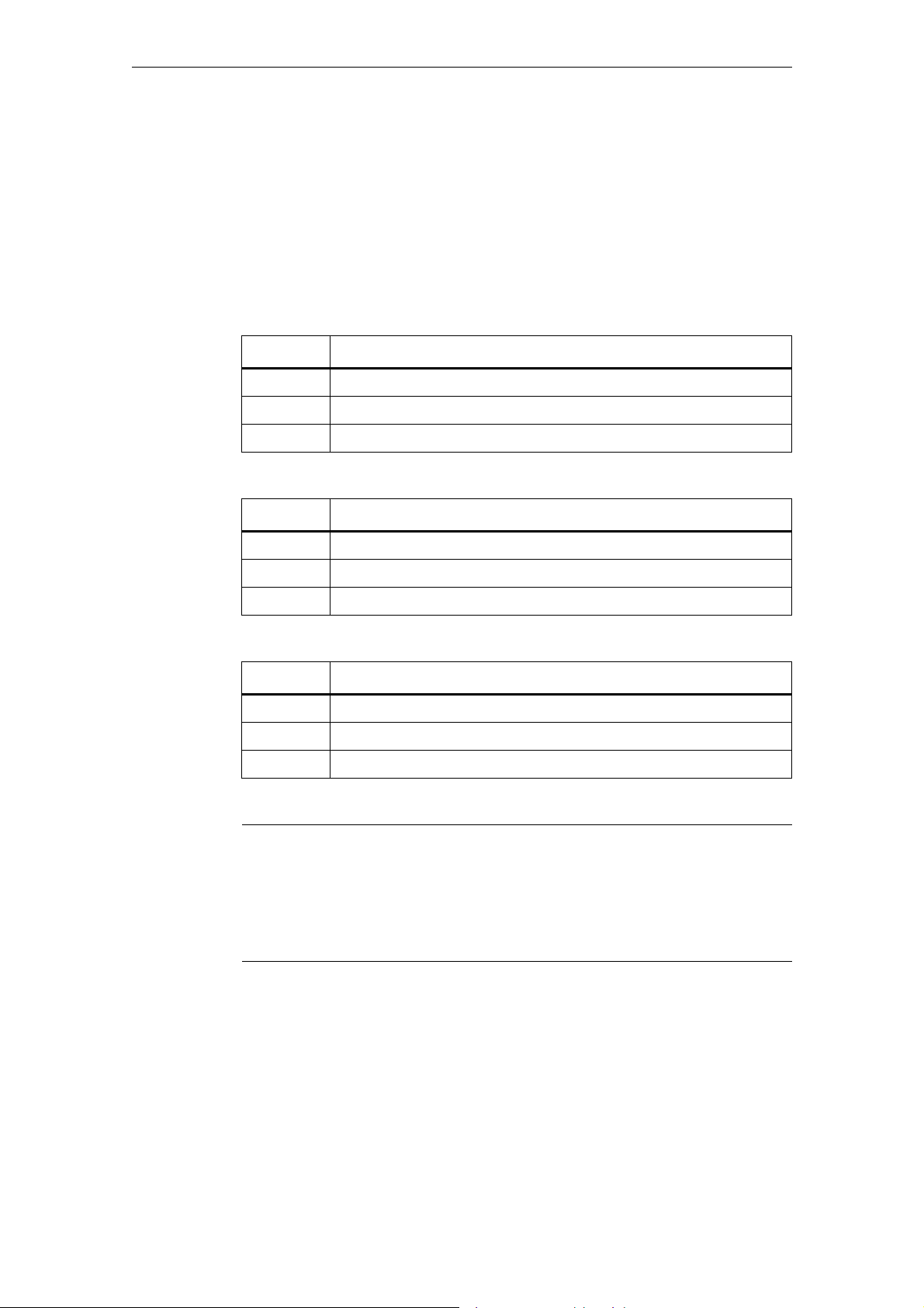
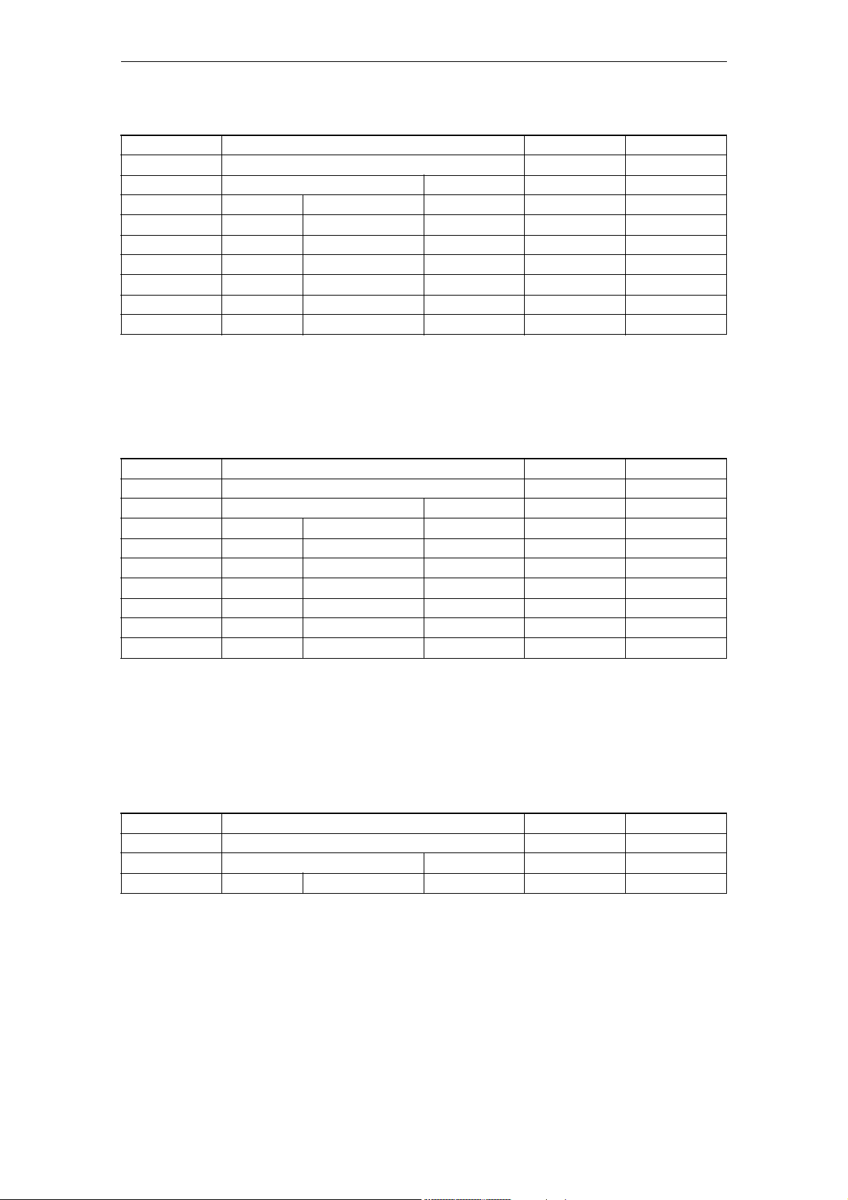
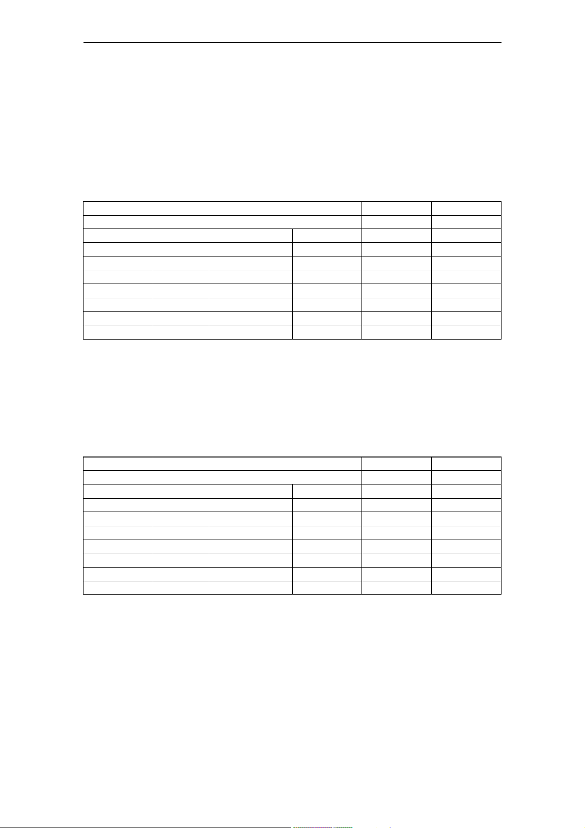
The machine and setting data are listed in the form of tables.
MD nummer MD identifier Cross
reference
Unit Brief description Activation
Display filter Attribute Data type
System Dimension Default value Minimalvalue Maximal value Protection
The following information are specified:
Number and identifier
MD and SD are addressed via their numbers or their names (identifiers). The
number and the name, as well as the activation type and the unit are displayed
on the screen of the control system.
Cross reference
In the field "
For a detailed description of the appropriate data, please refer to the description
of functions or manual/guide specified.
Example: [F-S1] Description of Functions 802D sl, Chapter "Spindle (S1)"
identifier", you can see the name of the data.
© Siemens AG 2007 All Rights Reserved
SINUMERIK 802D sl, Parameter Manual, 06/2007 Edition
1-11
Page 12

Machine and Setting Data - Explanation 06/2007
Specifications in the list
Unit/unit system
Depending on MD 10240 SCALING_SYSTEM_IS_METRIC, the physical units of
the machine data (MD) differ as follows:
MD 10240 = 1 MD 10240 = 0
mm inch
mm/min inch/min
m/s
m/s
2
3
inch/s
inch/s
2
3
mm/rev. inch/rev
If there are machine data with no physical unit assigned, a hyphen ("-") can be
found in the relevant field.
Hinweis:
The default setting is
MD 10240 SCALING_SYSTEM_IS_METRIC = 1 (metric)
Activation
In the "Activation" field, the following short designator specifies when the data
takes effect after a change.
po POWER ON "RESET" key on the front plate of the NCU module
cf NEW_CONF − The "Activate MD" softkey on the HMI
− "RESET" key on the control unit
− It is possible to modify block limits during program
operation
re RESET − at end of program M2/M30 or
− "RESET" key on the control unit
so IMMEDIATELY After entry of value
The levels of effectiveness have been listed above in order of priority.
Display filter
A short designator for the filter setting is listed in the "Display filter" field. With the
aid of this filter setting, it is possible to selectively reduce the number of the displayed machine/setting data of a section.
1-12
Display criteria:
EXP Expert mode:
• Active: the MD is assigned to the expert mode (display of MD)
© Siemens AG 2007 All Rights Reserved
SINUMERIK 802D sl, Parameter Manual, 06/2007 Edition
Page 13

06/2007 Machine and Setting Data - Explanation
Specifications in the list
Depending on the machine data section, there are different display filters. These
short designations return in the operator interface to activate the filters.
The short designations of the display filter and their meanings are listed below for
the individual machine data.
General machine data
N01 Configuration / Scaling
N02 Memory configuration
N03 PLC machine data
N04 Drive control
N05 Status data/Diagnostics
N06 Monitors/Limitations
N07 Auxiliary functions
N08 Corrections/Compensations
N09 Technological functions
N10 Peripheral configuration
N11 Standard machine
N12 NC language ISO dialect
Channelspecific machine data
C01 Configuration
C02 Memory configuration
C03 Initial settings
C04 Auxiliary functions
C05 Velocities
C06 Monitors/Limitations
C07 Transformations
C08 Corrections/Compensations
C09 Technological functions
C10 Standard machine
C11 NC language ISO dialect
© Siemens AG 2007 All Rights Reserved
SINUMERIK 802D sl, Parameter Manual, 06/2007 Edition
1-13
Page 14

Machine and Setting Data - Explanation 06/2007
Specifications in the list
Axis-specific machine data
A01 Configuration (including memory)
A02 Measuring system
A03 Machine geometry
A04 Speeds/Accelerations
A05 Monitors/Limitations
A06 Spindle
A07 Controller data
A08 Status data
A09 Corrections/Compensations
A10 Technological functions
O11 Standard machine
A12 NC language ISO dialect
Data type
In the "Data type" field, the short designators indicate the data types. The have
the following meanings:
BOOLEAN Boolean value: 1(TRUE) or 0 (FALSE)
BYT E I8-bit value
• as a INTEGER value. -128::: 127
• as a hexadecimal value: 00 ... FF
• as a character as per ASCII character set, e.g. “a”
STRING Sequence of characters (max. 16)
WORD 16-bit value,
• as an INTEGER value: -32768 ... 32767
• as a hexadecimal value: 0000 ... FFFF
UNSIGNED WORD I16-bit value,
• as an INTEGER value: 0 ... 65535,
• as a hexadecimal value: 0000 ... FFFF
INTEGER I16-bit value (here defined locally),
• INTEGER value: -32768 ... 32767
1-14
SINUMERIK 802D sl, Parameter Manual, 06/2007 Edition
© Siemens AG 2007 All Rights Reserved
Page 15

06/2007 Machine and Setting Data - Explanation
Specifications in the list
DWORD 32-bit value,
• as an INTEGER value: -2147483648 ... 2147483647
• as a hexadecimal value: 0000 0000 ... FFFF
UNSIGNED DWORD I32-bit value,
• as an INTEGER value: 0 ... 4294967295,
• as a hexadecimal value: 0000 0000 ... FFFF FFFF
DOUBLE 64-bit value,
• floating point value: ± 4.19 x 10
-307
to ± 1.67 x 10
308
)
System
FLOAT DWORD Realwerte (von ± 8,43 x 10
-37
bis "3,37 x 1038)
UBYTE Integerwerte (von 0 - 255)
LONG Integerwerte (von 4294967296 - 4294967295)
Specifies the control system for which the data with the entered values applies.
The following entries are possible:
• default
The entered values apply for all SINUMERIK 802D sl.
Any deviations in the range of values must be entered in the following lines of
the table. If no "default" entry exists, the data only applies for the control variants specified.
802d-cu3 Customised pro
802d-ng2 Nibbling/grinding plus
802d-ng3 Nibbling/grinding pro
802d-tm1 Turning/milling value
802d-tm2 Turning/milling plus
802d-tm3 Turning/milling pro
Default values
This value is used to specify a default value for the machine data. If the default
values for the channels are different, this is marked by a " , ".
Range of values (minimum/maximum value)
Specifies the input limits. If no range of values is specified, the data type determines the input limits, and the field is marked with "***".
If no range of values is specified, the value in the "Data type" field determines the
input limits and the field is marked with "***".
© Siemens AG 2007 All Rights Reserved
SINUMERIK 802D sl, Parameter Manual, 06/2007 Edition
1-15
Page 16

Machine and Setting Data - Explanation 06/2007
Specifications in the list
Protection
The SINUMERIK 802D sl provides a concept of protection levels for enabling data
areas.There are the protection levels 0 to 7 whereby 0 is the highest and 7 the
lowest level.The protection levels can be set for certain function areas (e.g. program editor) using thedisplay machine data (USER_CLASS...).When the control
system is delivered, certain default passwords are already set for the pro-tection
levels 1 to 3. If necessary, the appropriate authorized person can change these
pass-words.
Tabelle 1-1
Protection
level
0 Siemens, reserved
1 Password: SUNRISE
(default)
2 Password: EVENING
(default)
3 Password: CUSTOMER
(default)
4 to 7 No password anduser
interface from PLC NCK
Locked by Area
Expert mode (OEM HIGH)
Machine manufacturer (OEM LOW)
Authorized operator, setter
Authorized operator, setter or
appropriate graduations as desired
Protection levels 1 ... 3
The protection levels 1 to 3 require a password. The passwords can be changed
after activation. For example, if the passwords are no longer known, the control
system must be reini-tialized (booting with default machine data). This will reset
all passwords to their defaultsaccording to the software release you have
acquired.
The password remains set until it is reset by selecting the Delete password softkey. POWER ON will not reset the password.
1-16
Protection levels 4 ... 7
Protection level 7 is set automatically if no password is set and no protection level
interfacesignal is set. The protection levels 4 to 7 can be set from the PLC user
program even wi-thout a password by setting the bits in the user interface.
© Siemens AG 2007 All Rights Reserved
SINUMERIK 802D sl, Parameter Manual, 06/2007 Edition
Page 17

06/2007 Machine and Setting Data - Explanation
Overview of machine and setting data
1.2 Overview of machine and setting data
The machine data and setting data are divided into the following areas:
Tabelle 1-2 Overview of the machine and setting data areas
Area Designation
from 200 to 400 Display machine data1
from 1 000 to 19 999 General machine data
from 20 000 to 29 999 Channel-specific machine data
from 30 000 to 39 999 Axis-specific machine data
from 41 000 to 41 999 General setting data
from 42 000 to 42 999 Channel-specific setting data
from 43 000 to 43 999 Axis-specific setting data
© Siemens AG 2007 All Rights Reserved
SINUMERIK 802D sl, Parameter Manual, 06/2007 Edition
1-17
Page 18

Machine and Setting Data - Explanation 06/2007
Overview of machine and setting data
1-18
SINUMERIK 802D sl, Parameter Manual, 06/2007 Edition
© Siemens AG 2007 All Rights Reserved
Page 19
Machine Data 2
2.1 Display machine data
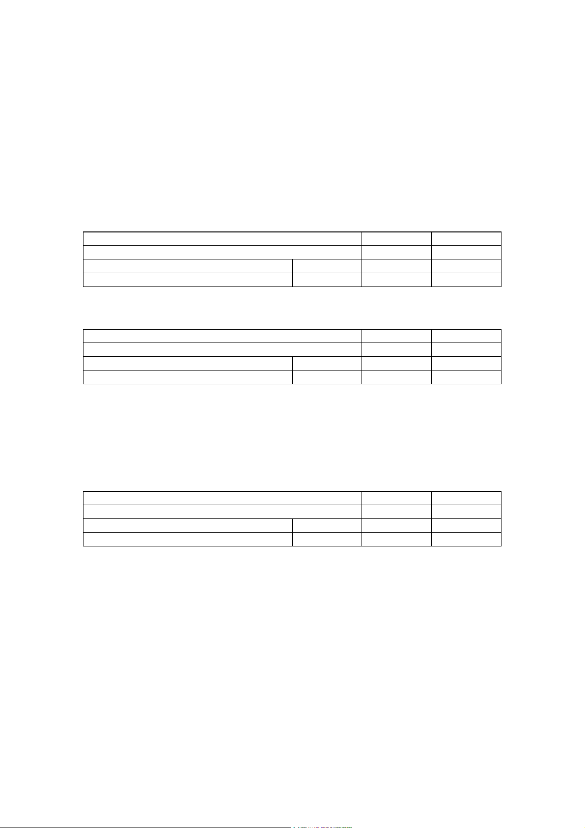
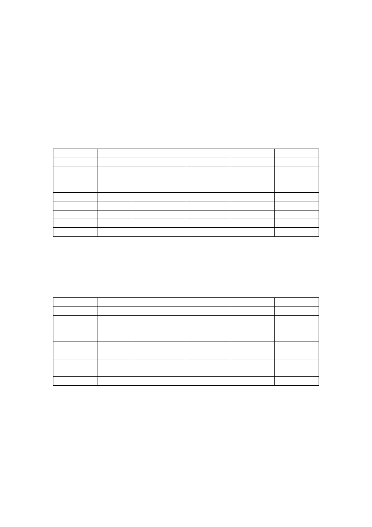
Number Identifier Display filters Reference
Unit Name Data type Active
Attributes
System Dimension Default value Minimum value Maximum value Protection
Description:
202 FIRST_LANGUAGE --
- Foreground language BYTE POWER ON
-
- 02 123/2
Description:
The language (1 or 2) which is to be automatically active after each system
startup is set in the machine data.
Two languages are available simultaneously in SINUMERIK 802D. Languages other
than those included in the control ex works can be loaded.
It is possible to temporarily switch to a second language using a softkey in
the Diagnosis area. After power ON the predefined language set in MD is again
active.
203 DISPLAY_RESOLUTION --
- Display resolution BYTE POWER ON
-
- 03 053/2
Description:
This machine data defines the number of places after the decimal point in the
position display for linear axes in metric systems as well as in general for
rotary axes.
Spindle positions are treated as rotary axis positions.
The position is displayed with 10 symbols max. including the plus/minus sign
and the decimal point. A plus sign is not displayed.
All 3 positions after the decimal point are displayed per default.⇒
MD value=3: Display resolution = 10-3 [mm] or [degrees].
related to:
MD 10200: INT_INCR_PER_MM or MD 10210: INT_INCR_PER_DEG
©Siemens AG 2007 All Rights Reserved
SINUMERIK 802D sl, Parameter Manual, 06/2007 Edition
2-19
Page 20
Machine Data 06/2007
Display machine data
204 DISPLAY_RESOLUTION_INCH --
- Display resolution for the INCH dimension system BYTE POWER ON
-
- 04 053/2
Description:
This machine data specifies the number of places after the decimal point for
linear axes for Inch dimension systems.
The position is displayed with max. 10 characters including the plus/minus
sign and the decimal point. A plus sign is not displayed.
All 4 positions after the decimal point are displayed per default.⇒
MD value=4: Display resolution = 10 -4 [inch]
The display is retained according to MD 203 for rotary axes and spindle
positions
related to:
MD 10200: INT_INCR_PER_MM, MD 203: DISPLAY_RESOLUTION
205 DISPLAY_RESOLUTION_SPINDLE --
- Display resolution for spindle values BYTE POWER ON
-
- 01 053/2
Description:
This machine data specifies the number of places after the decimal point of
the spindle speed display.
The values are displayed with 10 symbols max. including the plus/minus sign
and the decimal point. A plus sign is not displayed.
1 position after the decimal point is displayed per default.⇒
MD value=1: Display resolution = 10-1
289 CTM_SIMULATION_TIME_NEW_POS --
- Simulation updating rate of actual value INTEGER POWER ON
-
- 0 100 0 4000 4/3
Description:
This MD is set to specify the time intervals at which the simulation graphic
must be updated in accordance with the current machining process on the
machine tool.
Value = 0 means no update.
290 CTM_POS_COORDINATE_SYSTEM --
- Simulation of actual-value refresh rate BYTE POWER ON
-
- 02 074/3
Description:
The position of the coordinate system can be altered as follows:
2-20
SINUMERIK 802D sl, Parameter Manual, 06/2007 Edition
©Siemens AG 2007 All Rights Reserved
Page 21
06/2007 Machine Data
Display machine data
291 CTM_CROSS_AX_DIAMETER_ON --
- Diameter display for active transverse axes BYTE POWER ON
-
- 01 014/3
Description:
0: Inputs for absolute values as radius value.
Zero offsets always as radius,
tool lengths always as radius,
tool wear always as radius
1: Position display as diameter,
distance to go as diameter
absolute distances as diameter
292 CTM_G91_DIAMETER_ON --
- Incremental infeed BYTE POWER ON
-
- 01 017/3
Description:
0: Input in radius
1: Input in diameter
361 MEAS_TOOL_CHANGE --
- Input enable for T/D no. for tool measuring BYTE POWER ON
-
- -0 013/3
Description:
0: T/D number input blocked
1: T/D number input enabled
373 MEAS_SAVE_POS_LENGTH2 --
- Enable tool measuring SK "Save Pos" for all values. BYTE POWER ON
-
- -0 012/2
Description:
Controls "Save/Pos" softkey for "Manual tool measuring" function:
0: The SK "Save Pos" is only active when measuring length 1
1: SK "Save Pos" is generally active
©Siemens AG 2007 All Rights Reserved
SINUMERIK 802D sl, Parameter Manual, 06/2007 Edition
2-21
Page 22

Machine Data 06/2007
Generale maschine data
2.2 Generale maschine data
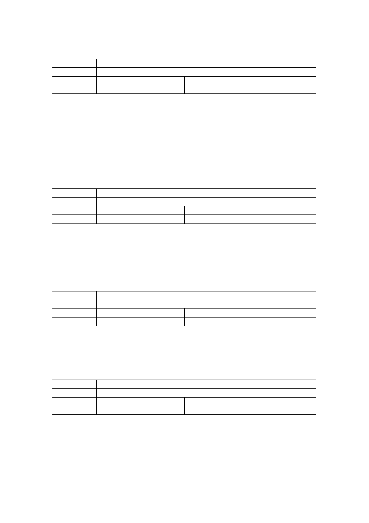
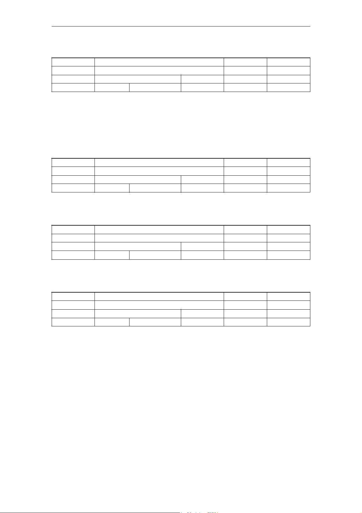
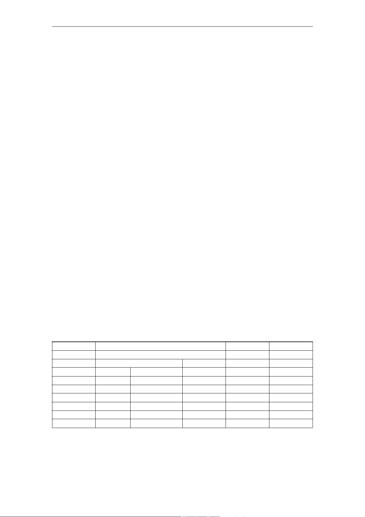
Number Identifier Display filters Reference
Unit Name Data type Active
Attributes
System Dimension Default value Minimum value Maximum value Protection
Description:
10000 AXCONF_MACHAX_NAME_TAB N01, N11 K2
- Machine axis name STRING POWER ON
-
- 31 "X1","Y1","Z1","A1","
B1","C1","U1"...
802d-cu3 6 "X1","Y1","Z1","SP","
A1","PLCX1"...
802d-ng2 6 "X1","Z1","C1","A1","
B1","PLCX1"...
802d-ng3 6 "X1","Z1","C1","A1","
B1","PLCX1"...
802d-tm1 4 "X1","Y1","Z1","SP" - - 2/2
802d-tm2 6 "X1","Y1","Z1","SP","
A1","PLCX1"...
802d-tm3 6 "X1","Y1","Z1","SP","
A1","PLCX1"...
--7/2
--2/2
--2/2
--2/2
--2/2
--2/2
Description:
The name of the machine axis is entered in this MD
- The preferred axis label (name) should be used comprising a valid address
letter
(A, B, C, Q, U, V, W, X, Y, Z), followed by an optional, numerical expansion
(1-99).
- The selected machine axis label (name) must differ from the label (name) of
geometry axes (X, Y, Z) and additional channel axes (MD 20080:
AXCONF_CHANAX_NAME_TAB if a transformation is planned (e.g.: TRANSMITT).
Comment: Transformation for SINUMERIK 802D, SW release P1, transformations are
not available.
- A "free" entered machine axis label (axis name) may not be a name, address,
keyword or predefined label or name that is already being used in the control
or is reserved for other functions (e.g.: SPOS, DIAMON, ...).
Note: Not all the SINUMERIK control system functions are documented for 802D.
Use of a free axis identifier is therefore conditional.
Special cases:
We recommend the following for machine axis identifiers:
X1, Y1, Z1, U1, V1, W1, Q1for linear axes,
A1, B1, C1for rotary axes
related to:
MD 20060: AXCONF_GEOAX_NAME_TAB (geometry axis identifier)
MD 20080 :AXCONF_CHANAX_NAME_TAB (channel axis identifier)
2-22
SINUMERIK 802D sl, Parameter Manual, 06/2007 Edition
©Siemens AG 2007 All Rights Reserved
Page 23
06/2007 Machine Data
Generale maschine data
10063 POSCTRL_CYCLE_DIAGNOSIS N01, N05, EXP s Active timing DOUBLE POWER ON
-, READ
-30.0 --7/2
802d-cu3 - - - - 0/802d-ng2 - - - - 0/802d-ng3 - - - - 0/802d-tm1 - - - - 0/802d-tm2 - - - - 0/802d-tm3 - - - - 0/-
Description:
Diagnostic data related to the PROFIBUS DP cycle.
[0]: Latest date at which the actual values must be available (Tdx)
[1]: Actually active position controller cycle offset (Tm)
[2]: Latest date at which the setpoints were output by the position controller
Diagnostic data are initialized with ZERO with each NCK power up
10074 PLC_IPO_TIME_RATIO N01, N05 -
- PLC task factor for main run (IPO) DWORD POWER ON
-
- - 1 1 50 0/0
802d-cu3 - - - - 2/2
802d-ng2 - - - - 2/2
802d-ng3 - - - - 2/2
802d-tm1 - - - - 2/2
802d-tm2 - - - - 2/2
802d-tm3 - - - - 2/2
Description:
Division ratio between IPO and PLC tasks.
A value of 2 means, for example, that the PLC task is processed in every
second IPO cycle only. The PLC cycle time therefore equals 2 IPO times. More
runtime is therefore available for the other tasks.
The PLC runtime must not exceed this PLC cycle time, or a PLC STOP alarm will
be triggered.
Anwendungsbeispiel:
10088 REBOOT_DELAY_TIME EXP s Reboot delay DOUBLE SOFORT
-
- - 0.2 0.0 1.0 2/2
Description:
The reboot following PI "_N_IBN_SS" is delayed by the time
$MN_REBOOT_DELAY_TIME.
The suppressable NOREADY alarm 2900 is activated immediately with PI
"_N_IBN_SS".
©Siemens AG 2007 All Rights Reserved
SINUMERIK 802D sl, Parameter Manual, 06/2007 Edition
2-23
Page 24
Machine Data 06/2007
Generale maschine data
If $MN_REBOOT_DELAY_TIME falls below the $MA_SERVO_DISABLE_DELAY_TIME value of
an axis, the axis is decelerated during $MN_REBOOT_DELAY_TIME. The servo
enable is disabled afterwards, i.e. the full $MA_SERVO_DISABLE_DELAY_TIME is
NOT waited.
Alarm 2900 does not become active with $MN_REBOOT_DELAY_TIME = 0.0 and there
is no reboot delay.
The NCK waits beyond the stated delay time until the PI has been able to be
acknowledged to the HMI. The delay time may total up to 2 s.
10200 INT_INCR_PER_MM N01 G2
- Calculation resolution for linear positions DOUBLE POWER ON
-
- - 1000. 1.0 1.0e9 7/2
802d-cu3 - - - - 2/2
802d-ng2 - 100000. - - 2/2
802d-ng3 - 100000. - - 2/2
802d-tm1 - - - - 2/2
802d-tm2 - - - - 2/2
802d-tm3 - - - - 2/2
Description:
The number of internal increments per millimeter is defined in this MD. The
precision of the linear position input is limited to the calculation
resolution by rounding-off the product of the programmed value and the
calculation resolution to an integer value. To make the rounding clear, powers
of 10 should be used for the calculation resolution.
Anwendungsbeispiel:
The calculation resolution can be increased to u1000 incr./mm for linear axes
operating to high accuracy requirements.
10210 INT_INCR_PER_DEG N01 G2
- Computational resolution for angular positions DOUBLE POWER ON
-
- - 1000.0 1.0 1.0e9 7/2
802d-cu3 - - - - 2/2
802d-ng2 - 100000. - - 2/2
802d-ng3 - 100000. - - 2/2
802d-tm1 - - - - 2/2
802d-tm2 - - - - 2/2
802d-tm3 - - - - 2/2
Description:
The number of internal increments per degree is defined in this MD. The
precision of the angular position input is limited to the calculation
resolution by rounding-off the product of the programmed value and the
calculation resolution to an integer value. To make the rounding clear, powers
of 10 should be used for the calculation resolution.
Anwendungsbeispiel:
The calculation resolution can be changed to u1000 incr./degrees for a highresolution rotary axis.
2-24
SINUMERIK 802D sl, Parameter Manual, 06/2007 Edition
©Siemens AG 2007 All Rights Reserved
Page 25

06/2007 Machine Data
Generale maschine data
10240 SCALING_SYSTEM_IS_METRIC N01 G2
- Basic system metric BOOLEAN POWER ON
SCAL
--TRUE--7/2
802d-cu3 - - - - 2/2
802d-ng2 - - - - 2/2
802d-ng3 - - - - 2/2
802d-tm1 - - - - 2/2
802d-tm2 - - - - 2/2
802d-tm3 - - - - 2/2
Description:
The MD defines the basic system used by the control to scale length-dependent
physical
quantities during data input/output.
All related data are stored internally in the basic units 1 mm, 1 degree and 1
sec.
When accessing a part program via the operator panel or from an external
device, scaling is in the
following units:
SCALING_SYSTEM_IS_METRIC = 1: normalized to:
mm, mm/min, m/s2, m/s3mm/rev
SCALING_SYSTEM_IS_METRIC = 0: normalized to:
inch, inch/min, inch/s2inch/s3, inch/rev
The selection of the basic system also specifies the interpretation of the
programmed F value for
linear axes:
metricinch
G94mm/mininch/min
G95mm/revinch/rev
A power-up is necessary after changing this machine data, as associated
machine data that have
physical units will otherwise be normalized incorrectly.
Perform the following steps:
- MD change by manual input
⇒ First perform start-up and then enter the physical units in the related
machine
data.
- MD change via machine data file
⇒ First perform start-up and then reload the machine data file
so that the new physical units are activated.
If the machine data are altered, alarm 4070 "Scaling machine data altered" is
output.
Anwendungsbeispiel:
Installation in the metric system and then conversion to inch system.
©Siemens AG 2007 All Rights Reserved
SINUMERIK 802D sl, Parameter Manual, 06/2007 Edition
2-25
Page 26

Machine Data 06/2007
Generale maschine data
10350 FASTIO_DIG_NUM_INPUTS N10 A4
- Number of active digital NCK input bytes BYTE POWER ON
-
- -1 057/2
802d-cu3 - 2 1 - 2/2
802d-ng2 - 2 1 - 2/2
802d-ng3 - 2 1 - 2/2
802d-tm1 - 2 1 - 2/2
802d-tm2 - 2 1 - 2/2
802d-tm3 - 2 1 - 2/2
Description:
The number of bytes of the digital NCK inputs that can be used on the control
are defined in this machine data.
These digital NCK inputs can be read directly by the part program. Moreover,
the signal state at the HW inputs can also be changed by the PLC.
If more digital NCK inputs are defined in the machine data than are available
in the control hardware, a signal status of 0 is set in the control for the
inputs that do not exist in the hardware. The NCK value can be altered by the
PLC.
Related to:
IS "Disable the digital NCK inputs" (DB10, DBB0, DBB122 ...)
IS "PLC setting for digital NCK inputs" (DB10, DBB1, DBB123 ...)
IS "Actual value for digital NCK inputs" (DB10, DBB60, DBB186 ...)
10360 FASTIO_DIG_NUM_OUTPUTS N10 A4
- Number of active digital NCK output bytes BYTE POWER ON
-
- -0 057/2
802d-cu3 - 2 - - 2/2
802d-ng2 - 2 - - 2/2
802d-ng3 - 2 - - 2/2
802d-tm1 - 2 - - 2/2
802d-tm2 - 2 - - 2/2
802d-tm3 - 2 - - 2/2
Description:
The number of bytes for digital NCK outputs that can be used on the control
are defined in this machine data.
These digital NCK outputs can be set directly by the part program. The PLC is
able to
- set the digital outputs to "0" in a defined way with IS "Disable the digital
NCK outputs".
- alter the NCK value with IS "Overwrite mask for digital NCK outputs".
- specify a PLC value with IS "Setting mask for digital NCK outputs".
2-26
SINUMERIK 802D sl, Parameter Manual, 06/2007 Edition
©Siemens AG 2007 All Rights Reserved
Page 27

06/2007 Machine Data
Generale maschine data
If more digital NCK outputs are defined in the machine data than are available
in the control hardware, no alarm is triggered. The signal states specified by
the part program can be read by the PLC.
Special cases:
Digital NCK outputs 5 to 8 can be processed only by the PLC (no hardware
outputs).
Related to:
IS "Disable the digital NCK outputs" (DB10, DBB4, DBB130 ...)
IS "Overwrite mask for digital NCK outputs" (DB10, DBB5, DBB131 ...)
IS "PLC setting for digital NCK outputs" (DB10, DBB6, DBB132 ...)
IS "Setting mask for digital NCK outputs" (DB10, DBB7, DBB133 ...)
IS "Setpoint for digital NCK outputs" (DB10, DBB64, DBB190 ...)
10366 HW_ASSIGN_DIG_FASTIN N10 A4
- Hardware assignment of external digital NCK inputs DWORD POWER ON
-
- 10 0x01000000 0x01000000 0x060003FF 7/2
802d-cu3 1 0x0 0x0 0x00010101 2/2
802d-ng2 1 0x00010101 0x0 0x00010101 2/2
802d-ng3 1 0x00010101 0x0 0x00010101 2/2
802d-tm1 1 0x0 0x0 0x00010101 2/2
802d-tm2 1 0x0 0x0 0x00010101 2/2
802d-tm3 1 0x0 0x0 0x00010101 2/2
Description:
The following 4 bytes assign the external digital NCK I/Os to the hardware:
1st byte: I/O no.
2nd byte: Submodule no.
3rd byte: Module no.
4th byte: Segment no.
As soon as value 0 is entered in byte 3 (module no.), the output byte
concerned is not processed by the control.
I/O no.:
Number of the I/O byte on the DP compact module (range: 1 to 2; always 1
with analog inputs/outputs)
Submodule no.:
Submodule slot on the terminal block into which the DP compact module is
inserted (range: 1 to 8)
Module no.:
Number of the logical slot into which the terminal block with the external
I/Os is inserted. The logical slot is assigned to a physical slot by MD
13010: DRIVE_LOGIC_NR (logical drive number). Each module occupies a
physical slot. The first 6 slots are permanently occupied on the 810D.
Segment no.:
Always 1 for 840D/810D (ID for 611D bus)
©Siemens AG 2007 All Rights Reserved
SINUMERIK 802D sl, Parameter Manual, 06/2007 Edition
2-27
Page 28

Machine Data 06/2007
Generale maschine data
Example:
HW_ASSIGN_DIGITAL_FASTIN[3] = 01 04 03 02
1st byte: 02 = 2nd input byte of a 16 bit input module
2nd byte: 03 = Input module inserted in slot 3 of the terminal block
3rd byte: 04 = Terminal block inserted at logical drive number 4
4th byte: 01 = ID for 611D bus
PROFIBUS DP:
Segment no.: 5 = PROFIBUS DP
6 = PROFIBUS DP link module
Module no.: 1 ... MD_MAXNUM_SIMO611D_AXES:
Number of the logical slot in which the terminal block with the external
I/Os is inserted. The logical slot is assigned to a physical slot by
$MN_DRIVE_LOGIC_NR, it is activated by $MN_DRIVE_IS_ACTIVE.
1st + 2nd bytes give the logical start address of the I/O slot on the PROFIBUS
1st byte = low byte
2nd byte = high byte
Value 0000 means NO active slots
Values 0001..007F are reserved for the PLC (NCK can also read the value for
input slots without error, but output slots are forbidden in this range and
lead to an alarm during startup)
Values 0080..02FF are valid
Values > 02FF are invalid
Example:
HW_ASSIGN_DIGITAL_FASTIN[3] = '05000302'
1st + 2nd byte: 0302 (hex) = logical start address 770 (decimal)
3rd byte: 00 = no significance
4th byte: 05 = ID for PROFIBUS DP
Related to:
MD 10368: HW_ASSIGN_DIG_FASTOUT
MD 10362: HW_ASSIGN_ANA_FASTIN
MD 10364: HW_ASSIGN_ANA_FASTOUT
10368 HW_ASSIGN_DIG_FASTOUT N10 A4
- Hardware assignment of external digital NCK outputsDWORD POWER ON
-
- 4 0x01000000 0x01000000 0x060003FF 7/2
802d-cu3 1 0x0 0x0 0x00010101 2/2
802d-ng2 1 0x00010101 0x0 0x00010101 2/2
802d-ng3 1 0x00010101 0x0 0x00010101 2/2
802d-tm1 1 0x0 0x0 0x00010101 2/2
802d-tm2 1 0x0 0x0 0x00010101 2/2
802d-tm3 1 0x0 0x0 0x00010101 2/2
Description:
The following 4 bytes assign the external digital NCK outputs to the hardware:
1st byte: I/O no.
2nd byte: Submodule no.
3rd byte: Module no.
4th byte: Segment no.
2-28
SINUMERIK 802D sl, Parameter Manual, 06/2007 Edition
©Siemens AG 2007 All Rights Reserved
Page 29
06/2007 Machine Data
Generale maschine data
As soon as value 0 is entered in byte 3 (module no.), the output byte
concerned is not processed by the control.
The hardware assignment is control specific and therefore different on the
SINUMERIK 840D/810D and FM-NC.
The individual bytes are explained under MD: HW_ASSIGN_DIG_FASTIN.
[hw] = Index (0 to 3) for addressing the external digital output bytes
Related to:
MD 10366: HW_ASSIGN_DIG_FASTIN
MD 10362: HW_ASSIGN_ANA_FASTIN
MD 10364: HW_ASSIGN_ANA_FASTOUT
10400 CC_VDI_IN_DATA EXP, N02 OEM
- Number of input bytes for compile cycles DWORD POWER ON
-
- - 0 0 1024 7/1
802d-cu3 - - - - -1/802d-ng2 - - - - -1/802d-ng3 - - - - -1/802d-tm1 - - - - -1/802d-tm2 - - - - -1/802d-tm3 - - - - -1/-
Description:
The compile cycle user can freely define data within a data block on the PLC
user interface. As the user, he determines the size of the interface from PLC
to NCK. This machine data describes the length of the area on the VDI
interface in bytes which defines the NCK input interface. The sum of this MD
and the machine data CC_VDI_OUT_DATA must not exceed 400 for software version
1.
10410 CC_VDI_OUT_DATA EXP, N02 OEM
- Number of output bytes for compile cycles DWORD POWER ON
-
- - 0 0 1024 7/1
802d-cu3 - - - - -1/802d-ng2 - - - - -1/802d-ng3 - - - - -1/802d-tm1 - - - - -1/802d-tm2 - - - - -1/802d-tm3 - - - - -1/-
Description:
The compile cycle user can freely define data within a data block on the PLC
user interface. As the user, he determines the size of the interface from PLC
to NCK. This machine data describes the length of the area on the VDI
interface in bytes which defines the NCK output interface. The sum of this MD
and the machine data CC_VDI_IN_DATA must not exceed 400.
©Siemens AG 2007 All Rights Reserved
SINUMERIK 802D sl, Parameter Manual, 06/2007 Edition
2-29
Page 30

Machine Data 06/2007
Generale maschine data
10420 CC_ASSIGN_FASTOUT_MASK EXP, N10 OEM
- Reservation of external outputs for compile cycles DWORD POWER ON
-
--0 --7/2
802d-cu3 - - - - -1/802d-ng2 - - - - -1/802d-ng3 - - - - -1/802d-tm1 - - - - -1/802d-tm2 - - - - -1/802d-tm3 - - - - -1/-
Description:
Reservation of high-speed hardware outputs for CC applications
Bit 0(LSB)-14: Mask of the digital output bytes reserved for the CC
application
Bits 16-30: Mask of the analog outputs reserved for the CC application
The hardware outputs reserved here are included in the multiple assignment
monitoring routine when the system is powered up. It is recommended to
register all the hardware outputs used by CC applications here.
Bit 15: Suppresses power-up alarm 4275 (multiple assignment of digital output)
Bit 31: Suppresses power-up alarm 4275 (multiple assignment of analog output)
10450 SW_CAM_ASSIGN_TAB N09 N3
- Assignment of software cams to machine axes BYTE POWER ON
-
-320 0317/2
802d-cu3 8 - - - 2/2
802d-ng2 8 - - - 2/2
802d-ng3 8 - - - 2/2
802d-tm1 1 - - - 0/0
802d-tm2 1 - - - 0/0
802d-tm3 1 - - - 0/0
Description:
This machine data allows one machine axis to be assigned to each of the 16
possible cam pairs (each is comprised of one minus and one plus cam).
If a "0" is entered, the corresponding cam is not processed.
The cam signal output is activated via the axial IS "Cam activation" (DB31-48,
DBX2.0).
Index [n] of the machine data addresses the cam pair: n = 0, 1, ... , 15
correspond to cam pairs 1, 2, ... , 16
Related to IS "Cam activation" (DB31-48, DBX2.0)
2-30
SINUMERIK 802D sl, Parameter Manual, 06/2007 Edition
©Siemens AG 2007 All Rights Reserved
Page 31

06/2007 Machine Data
Generale maschine data
Example:
Cam pair 1 is to be assigned to machine axis 3 and cam pair 3 to machine axis
4. Cam pair 2 is not to be assigned to an axis.
MD: SW_CAM_ASSIGN_TAB[0]= 3
MD: SW_CAM_ASSIGN_TAB[1]= 0
MD: SW_CAM_ASSIGN_TAB[2]= 4
10460 SW_CAM_MINUS_LEAD_TIME N09 N3
s Lead or delay time at minus cams 1-16 DOUBLE POWER ON
-
-320.0 --7/2
802d-cu3 8 - - - 3/3
802d-ng2 8 - - - 3/3
802d-ng3 8 - - - 3/3
802d-tm1 1 - - - 0/0
802d-tm2 1 - - - 0/0
802d-tm3 1 - - - 0/0
Description:
A lead or delay time can be assigned in this machine data to each minus cam 116 to compensate for delay times.
The switching edge of the associated cam signal is advanced or delayed by the
time value entered.
Positive value: --> Lead time
Negative value: --> Delay time
Serves to compensate for the constant proportion of the internal delay time
between actual value acquisition and signal output.
Index [n] of the machine data addresses the cam pair:
n = 0, 1, ... , 15 correspond to cam pairs 1, 2, ... , 16
This machine data is added to the setting data SW_CAM_MINUS_TIME_TAB_1[n] and
SW_CAM_MINUS_TIME_TAB_2[n].
Related to:
SD: SW_CAM_MINUS_TIME_TAB_1[n] (lead or delay time on minus cams 1 - 8)
SD: SW_CAM_MINUS_TIME_TAB_2[n] (lead or delay time on minus cams 9 - 16)
10461 SW_CAM_PLUS_LEAD_TIME N09 N3
s Lead or delay time at plus cams 1-16 DOUBLE POWER ON
-
-320.0 --7/2
802d-cu3 8 - - - 3/3
802d-ng2 8 - - - 3/3
802d-ng3 8 - - - 3/3
802d-tm1 1 - - - 0/0
802d-tm2 1 - - - 0/0
802d-tm3 1 - - - 0/0
©Siemens AG 2007 All Rights Reserved
SINUMERIK 802D sl, Parameter Manual, 06/2007 Edition
2-31
Page 32

Machine Data 06/2007
Generale maschine data
Description:
A lead or delay time can be assigned in this machine data to each plus cam 116 to compensate for delay times.
The switching edge of the associated cam signal is advanced or delayed by the
time value entered.
Positive value: --> Lead time
Negative value: --> Delay time
Serves to compensate for the constant proportion of the internal delay time
between actual value acquisition and signal output.
Index [n] of the machine data addresses the cam pair:
n = 0, 1, ... , 15 correspond to cam pairs 1, 2, ... , 16
This machine data is added to the setting data SW_CAM_PLUS_TIME_TAB_1[n] and
SW_CAM_PLUS_TIME_TAB_2[n].
Related to:
SD: SW_CAM_PLUS_TIME_TAB_1[n] (lead or delay time on plus cams 1 - 8)
SD: SW_CAM_PLUS_TIME_TAB_2[n] (lead or delay time on plus cams 9 - 16)
10470 SW_CAM_ASSIGN_FASTOUT_1 N09 N3
- Hardware assignment for output of cams 1-8 to NCK
I/Os
-
--0 --7/2
802d-cu3 - - - - 2/2
802d-ng2 - - - - 2/2
802d-ng3 - - - - 2/2
802d-tm1 - - - - 0/0
802d-tm2 - - - - 0/0
802d-tm3 - - - - 0/0
Description:
The cam signal status can be output to the NCK I/Os as well as to the PLC.
The hardware assignment of the minus and plus cam signals to the digital
output bytes used for the NCK I/Os is made in this machine data for cam pairs
1 - 8.
The assigned output signals can also be inverted with this machine data.
The MD is coded as follows:
Bits 0-7: No. of 1st HW byte used with digital outputs
Bits 8-15: No. of 2nd HW byte used with digital outputs
Bits 16-23: Inversion mask for writing 1st HW byte used
Bits 24-31: Inversion mask for writing 2nd HW byte used
Bit=0: Do not invert
Bit=1: Invert
DWORD POWER ON
If both HW bytes are specified, the 1st byte contains the minus cam signals
and the 2nd byte the plus cam signals.
2-32
SINUMERIK 802D sl, Parameter Manual, 06/2007 Edition
©Siemens AG 2007 All Rights Reserved
Page 33

06/2007 Machine Data
Generale maschine data
If the 2nd byte is not specified (= "0"), then the 8 cams are output as an AND
operation of the minus and plus cam signals via the 1st HW byte using the 1st
inversion mask.
The status of the non-inverted output signal for linear axes and for rotary
axes with "plus cam - minus cam < 180 degrees" is:
"1" between minus and plus cams
"0" outside this range
The status of the non-inverted output signal for rotary axes with "plus cam minus cam >= 180 degrees" is:
"0" between minus and plus cams
"1" outside this range
The following must be specified as the byte address for the digital outputs:
1: for on-board byte
2 - 5: for external bytes
10480 SW_CAM_TIMER_FASTOUT_MASK N09 N3
- Mask for output of cam signals via timer interr. to
NCU
-
--0 --7/2
802d-cu3 - - - - 2/2
802d-ng2 - - - - 2/2
802d-ng3 - - - - 2/2
802d-tm1 - - - - 0/0
802d-tm2 - - - - 0/0
802d-tm3 - - - - 0/0
DWORD POWER ON
Description:
A timer-controlled output to the 4 on-board outputs of the NCK I/Os can be
selected in this machine data for 4 cam pairs.
In this case, the minus and plus signals of a cam pair are EXCLUSIVE OR'd for
output as one signal.
Meaning for set bit:
Associated cam (minus and plus cam signals EXCLUSIVE OR'd) is output via a
timer interrupt at one of the 4 on-board outputs of the NCU.
The on-board outputs are assigned in order of increasing machine axis numbers
(with assigned cam pairs).
Example:
Machine axis 3 = cam pair 1 --> on-board output 3
Machine axis 1 = cam pair 2 --> on-board output 1
Machine axis 7 = cam pair 3 --> on-board output 4
Machine axis 2 = cam pair 4 --> on-board output 2
If a plurality of cam pairs are set for one machine axis, then this axis is
assigned in ascending order of the cam pairs.
©Siemens AG 2007 All Rights Reserved
SINUMERIK 802D sl, Parameter Manual, 06/2007 Edition
2-33
Page 34

Machine Data 06/2007
Generale maschine data
Example:
Machine axis 3 = cam pair 1 --> on-board output 2
Machine axis 3 = cam pair 2 --> on-board output 3
Machine axis 7 = cam pair 3 --> on-board output 4
Machine axis 2 = cam pair 4 --> on-board output 1
This function works independently of the assignment set in MD:
SW_CAM_ASSIGN_FASTOUT_1 or MD: SW_CAM_ASSIGN_FASTOUT_2.
Note:
The on-board byte must not be used more than once.
If there is more than one signal change in the IPO cycle for the cam pairs
specified in the MD, then the cam pair with the lowest number determines the
instant of output. The other signal changes take place at the same time.
10485 SW_CAM_MODE N09 N3
- Behavior of SW cams DWORD POWER ON
-
--0 --7/2
802d-cu3 - - - - 2/2
802d-ng2 - - - - 2/2
802d-ng3 - - - - 2/2
802d-tm1 - - - - 0/0
802d-tm2 - - - - 0/0
802d-tm3 - - - - 0/0
Description:
Meaning of the individual bits:
Bit 0(LSB) = 0:
If more than 1 signal change per interpolation cycle is due for the cams
specified in MD SW_CAM_TIMER_FASTOUT_MASK, the cam having the lowest number
will determine the output instant. The other signals change at the same
instant. That is, a maximum of one interrupt-controlled output is effected
per interpolation cycle.
Bit 0(LSB) = 1:
Each cam specified in MD SW_CAM_TIMER_FASTOUT_MASK will be output precisely
at the time of the interpolation cycle. There is no output priority of the
cams. A maximum of 8 interrupt-controlled outputs can be performed per
interpolation cycle.
Bit 1 = 0:
Inversion of signal behavior from plus cam where plus cam - minus cam >=
180 degr .
Bit 1 = 1:
No inversion of signal behavior from plus cam where plus cam - minus cam >=
2-34
SINUMERIK 802D sl, Parameter Manual, 06/2007 Edition
©Siemens AG 2007 All Rights Reserved
Page 35

06/2007 Machine Data
Generale maschine data
180 degr.
Signal behavior on-board output:
Overtravelling:
Minus cam plus cam
Traversing direction:
positive 0->1 1->0
negative 1->0 0->1
Bit 2 = 0:
No path-time cam
Bit 2 = 1:
Path-time cam for cams where minus position = plus position. The lead/delay
time applied is independent of:
- velocity of the axis
- position of the axis
- reversal of traversing direction
The cam is only activated on overtravelling of the cam position. A
lead/delay time applied to the minus cam is active and leads to a shift of
the whole cam.
Bit 3 = 0:
No alignment signal in case of measurement area selection.
Bit 3 = 1:
Output of an alignment signal for measurement area selection (FM only). On-
board output 8 is used permanently.
On-board output 8 = 1: Measurement possible (active range enabled)
On-board output 8 = 0: Measurement not possible
Bit 4 = 0:
and following free
10500 DPIO_LOGIC_ADDRESS_IN N10 -
- Logical slot address of the PROFIBUS I/Os DWORD POWER ON
-
- MD_MAXNU
M_DPIO_RA
NGE_IN
802d-cu3 - - - - -1/802d-ng2 - - - - -1/802d-ng3 - - - - -1/802d-tm1 - - - - -1/802d-tm2 - - - - -1/802d-tm3 - - - - -1/-
0 0 8191 7/2
Description:
Logical slot address of the PROFIBUS I/Os usable by the NCK.
The logical slot address is defined in STEP 7, hardware configuration.
©Siemens AG 2007 All Rights Reserved
SINUMERIK 802D sl, Parameter Manual, 06/2007 Edition
2-35
Page 36

Machine Data 06/2007
Generale maschine data
10501 DPIO_RANGE_LENGTH_IN N10 -
- Length of the PROFIBUS I/O range DWORD POWER ON
-
- MD_MAXNU
M_DPIO_RA
NGE_IN
802d-cu3 - - - - -1/802d-ng2 - - - - -1/802d-ng3 - - - - -1/802d-tm1 - - - - -1/802d-tm2 - - - - -1/802d-tm3 - - - - -1/-
Description:
Length of the PROFIBUS I/O range consistently usable for the NCK. This range
must be defined in STEP 7, hardware configuration.
0: only the first data slot is used.
x: length of the consistent PROFIBUS I/O range
0 0 MD_MAXNUM_D
PIO_BYTES_RA
NGE_IN
7/2
10502 DPIO_RANGE_ATTRIBUTE_IN N10 -
- Attributes of the PROFIBUS I/Os DWORD POWER ON
-
- MD_MAXNU
M_DPIO_RA
NGE_IN
802d-cu3 - - - - -1/802d-ng2 - - - - -1/802d-ng3 - - - - -1/802d-tm1 - - - - -1/802d-tm2 - - - - -1/802d-tm3 - - - - -1/-
Description:
Attributes of the PROFIBUS I/Os
Bit 0: Little/Big Endian format of the system variable $A_DPx_IN[n,m]
0: Little Endian format
1: Big Endian format
Bit 1: (reserved)
Bit 2: Read input data
0: Read possible through system variable and CC binding (increased
performance requirements)
1: Read only possible for CC binding (low performance requirements)
0x01 0x00 0x0F 7/2
Bit 3: Slot sign-of-life alarm
0: Slot sign-of-life alarms are output
1: Slot sign-of-life alarms are suppressed
2-36
SINUMERIK 802D sl, Parameter Manual, 06/2007 Edition
©Siemens AG 2007 All Rights Reserved
Page 37

06/2007 Machine Data
Generale maschine data
10510 DPIO_LOGIC_ADDRESS_OUT N10 -
- Logical slot address of the PROFIBUS I/Os DWORD POWER ON
-
- MD_MAXNU
M_DPIO_RA
NGE_OUT
802d-cu3 - - - - -1/802d-ng2 - - - - -1/802d-ng3 - - - - -1/802d-tm1 - - - - -1/802d-tm2 - - - - -1/802d-tm3 - - - - -1/-
Description:
Logical slot address of the PROFIBUS I/Os usable by the NCK.
The logical slot address is defined in STEP 7, hardware configuration.
0 0 8191 7/2
10511 DPIO_RANGE_LENGTH_OUT N10 -
- Length of the PROFIBUS I/O range DWORD POWER ON
-
- MD_MAXNU
M_DPIO_RA
NGE_OUT
802d-cu3 - - - - -1/802d-ng2 - - - - -1/802d-ng3 - - - - -1/802d-tm1 - - - - -1/802d-tm2 - - - - -1/802d-tm3 - - - - -1/-
Description:
Length of the PROFIBUS I/O range consistently usable for the NCK. This range
must be defined in STEP 7, hardware configuration.
0: only the first data slot is used.
x: length of the consistent PROFIBUS I/O range
10512 DPIO_RANGE_ATTRIBUTE_OUT N10 -
- Attributes of the PROFIBUS I/Os DWORD POWER ON
-
- MD_MAXNU
M_DPIO_RA
NGE_OUT
802d-cu3 - - - - -1/802d-ng2 - - - - -1/802d-ng3 - - - - -1/802d-tm1 - - - - -1/802d-tm2 - - - - -1/802d-tm3 - - - - -1/-
0 0 MD_MAXNUM_D
PIO_BYTES_RA
NGE_OUT
0x01 0x00 0x0F 7/2
7/2
©Siemens AG 2007 All Rights Reserved
SINUMERIK 802D sl, Parameter Manual, 06/2007 Edition
2-37
Page 38

Machine Data 06/2007
Generale maschine data
Description:
Attributes of the PROFIBUS I/Os
Bit 0: Little/Big Endian format of system variable $A_DPx_OUT[n,m]
0: Little Endian format
1: Big Endian format
Bit 1: Write output data
0: Write only through system variable
1: Write only through CC binding
Bit 2: (reserved)
Bit 3: Slot sign-of-life alarm
0: Slot sign-of-life alarms are output
1: Slot sign-of-life alarms are suppressed
10618 PROTAREA_GEOAX_CHANGE_MODE EXP, N01, N09 A3
- Protection range on change of geometry axes BYTE POWER ON
-
- -0 037/2
802d-cu3 - - - - 1/1
802d-ng2 - - - - 1/1
802d-ng3 - - - - 1/1
802d-tm1 - - - - -1/802d-tm2 - - - - -1/802d-tm3 - - - - -1/-
Description:
This machine data is used to define whether any active protection zones will
remain active after a transformation change or geo axis replacement, or
whether they will be deactivated.
The machine data is bit-coded with the following meanings:
Bit 0 = 0
Protection zones deactivated on transformation change.
Bit 0 = 1
Active protection zones remain active after transformation change.
Bit 1 = 0
Protection zones deactivated on geo axis replacement.
Bit 1 = 1
Active protection zones remain active after geo axis replacement.
2-38
SINUMERIK 802D sl, Parameter Manual, 06/2007 Edition
©Siemens AG 2007 All Rights Reserved
Page 39

06/2007 Machine Data
Generale maschine data
10710 PROG_SD_RESET_SAVE_TAB EXP, N01 K1
- Setting data to be updated DWORD POWER ON
-
-300 --7/2
802d-cu3 - - - - 2/2
802d-ng2 - - - - 2/2
802d-ng3 - - - - 2/2
802d-tm1 - - - - 1/1
802d-tm2 - - - - 2/2
802d-tm3 - - - - 2/2
Description:
Setting data to be backed up
The values of the SDs listed in this table are stored in non-volatile memory,
i.e. remain valid after power ON. The setting data whose HMI numbers were
entered in the backup list are written into the (buffered) active file system
after the description of the part program on RESET.
Programmable setting data are:
(GCODE)
SD 42000 $SC_THREAD_START_ANGLE SF
SD 42400 $SC_PUNCH_DWELLTIME PDELAYON
SD 42800 $SC_SPIND_ASSIGN_TAB SETMS
SD 43210 $SA_SPIND_MIN_VELO_G25 G25
SD 43220 $SA_SPIND_MAX_VELO_G26 G26
SD 43230 $SA_SPIND_MAX_VELO_LIMS LIMS
SD 43300 $SA_ASSIGN_FEED_PER_REV_SOURCE FPRAON
SD 43420 $SA_WORKAREA_LIMIT_PLUS WALIMOF
SD 43430 $SA_WORKAREA_LIMIT_MINUS WALIMON
SD 43510 $SA_FIXED_STOP_TORQUE FXST
SD 43520 $SA_FIXED_STOP_WINDOW FXSW
SD 43700 $SA_OSCILL_REVERSE_POS1 OSP1
SD 43710 $SA_OSCILL_REVERSE_POS2 OSP2
SD 43720 $SA_OSCILL_DWELL_TIME1 OST1
SD 43730 $SA_OSCILL_DWELL_TIME2 OST2
SD 43740 $SA_OSCILL_VELO FA
SD 43750 $SA_OSCILL_NUM_SPARK_CYCLES OSNSC
SD 43760 $SA_OSCILL_END_POS OSE
SD 43770 $SA_OSCILL_CTRL_MASK OSCTRL
SD 43780 $SA_OSCILL_IS_ACTIVE OS
The values of SD 43420: WORKAREA_LIMIT_PLUS (working area limitation plus) and
SD 43430: WORKAREA_LIMIT_MINUS (working area limitation minus) are to be
stored in the buffered RAM after every RESET, M02, M30 or M17.
--> PROG_SD_RESET_SAVE_TAB[0] = 43420
--> PROG_SD_RESET_SAVE_TAB[1] = 43430
©Siemens AG 2007 All Rights Reserved
SINUMERIK 802D sl, Parameter Manual, 06/2007 Edition
2-39
Page 40

Machine Data 06/2007
Generale maschine data
10713 M_NO_FCT_STOPRE EXP, N12, N07 -
- M function with preprocessing stop DWORD POWER ON
-
-15-1 --7/2
802d-cu3 - - - - 2/2
802d-ng2 - - - - 2/2
802d-ng3 - - - - 2/2
802d-tm1 - - - - 2/2
802d-tm2 - - - - 2/2
802d-tm3 - - - - 2/2
Description:
The M functions defined by machine data $MN_M_NO_FCT_STOPRE perform an
implicit preprocessing stop.
That is, the interpretation of the next part program line will be stopped
until the block with the M function defined in that way has been processed
completely
(PLC acknowledgement, motion, etc.).
10714 M_NO_FCT_EOP EXP, N07 S1
- M function for spindle active after reset DWORD POWER ON
-
---1 --7/2
802d-cu3 - - - - 2/2
802d-ng2 - - - - 2/2
802d-ng3 - - - - 2/2
802d-tm1 - - - - 2/2
802d-tm2 - - - - 2/2
802d-tm3 - - - - 2/2
Description:
For spindles where a '2' is configured in $MA_SPIND_ACTIVE_AFTER_RESET, no
spindle reset is enabled with this M function when the part program is
terminated. The spindle therefore remains active after the end of the part
program.
Proposal: M32
Restrictions: see machine data 10715: $MN_M_NO_FCT_CYCLE
Related to:
$MA_SPIND_ACTIVE_AFTER_RESET
$MN_M_NO_FCT_EOP,
$MN_M_NO_FCT_CYCLE,
$MC_SPIND_RIGID_TAPPING_M_NR,
$MC_AUXFU_ASSOC_M0_VALUE
2-40
SINUMERIK 802D sl, Parameter Manual, 06/2007 Edition
©Siemens AG 2007 All Rights Reserved
Page 41

06/2007 Machine Data
Generale maschine data
For external language mode:
$MN_EXTERN_M_NO_MAC_CYCLE,
$MN_EXTERN_M_NO_SET_INT
$MN_EXTERN_M_NO_DISABLE_INT,
$MN_EXTERN_CHAN_SYNC_M_NO_MIN,
$MN_EXTERN_CHAN_SYNC_M_NO_MAX
$MC_EXTERN_RIGID_TAPPING_M_NR
For nibbling:
$MC_NIBBLE_PUNCH_CODE
10715 M_NO_FCT_CYCLE EXP, N12, N07 FBFA,K1
- M function to be replaced by a subroutine DWORD POWER ON
-
-10-1 --7/2
802d-cu3 - - - - 2/2
802d-ng2 - - - - 2/2
802d-ng3 - - - - 2/2
802d-tm1 - - - - 2/2
802d-tm2 - - - - 2/2
802d-tm3 - - - - 2/2
Description:
M number with which a subprogram is called.
The name of the subprogram is stated in $MN_M_NO_FCT_CYCLE_NAME[n]. If the M
function defined with $MN_M_NO_FCT_CYCLE[n] is programmed in a part program
block, the subprogram defined in M_NO_FCT_CYCLE_NAME[n] is started at the end
of the block. If the M function is programmed again in the subprogram,
substitution by a subprogram call is then not carried out.
$MN_M_NO_FCT_CYCLE[n] acts both in Siemens mode G290 and in external language
mode G291.
The subprograms configured with $MN_M_NO_FCT_CYCLE_NAME[n] and
$MN_T_NO_FCT_CYCLE_NAME must not be active simultaneously in one block (line
of a part program). That means no more than one M/T function replacement can
be active in any one block. Neither an M98 nor a modal subprogram call can be
programmed in a block with the M function replacement.
Subprogram return and end of part program are also not permitted. Alarm 14016
is output in the event of a conflict.
Restrictions:
M functions with a fixed meaning and configurable M functions are checked for
conflicting settings. A conflict is reported with an alarm.
The following M functions are checked:
- M0 to M5,
- M17,M30,
- M19,
- M40 to M45,
- M function for 'Spindle active after part program end' according to machine
data $MN_M_NO_FCT_EOP
- M function for subprogram calls according to machine data $MN_M_NO_FCT_CYCLE
- M function for spindle/axis mode switchover according to machine data
$MC_SPIND_RIGID_TAPPING_M_NR
- Additional M function for program stop according to machine data
$MC_AUXFU_ASSOC_M0_VALUE
©Siemens AG 2007 All Rights Reserved
SINUMERIK 802D sl, Parameter Manual, 06/2007 Edition
2-41
Page 42
Machine Data 06/2007
Generale maschine data
- Additional M function for conditional program stop according to machine data
$MC_AUXFU_ASSOC_M1_VALUE
For external language mode only:
- M function for 'Macro call via M function' according to machine data
$MN_EXTERN_M_NO_MAC_CYCLE
- M functions for interrupt programming according to configuration by
$MN_EXTERN_M_NO_SET_INT and $MN_EXTERN_M_NO_DISABLE_INT
- M functions for channel synchronisation according to configuration by
$MN_EXTERN_CHAN_SYNC_M_NO_MIN und $MN_EXTERN_CHAN_SYNC_M_NO_MAX
- M function for spindle/axis mode switchover with external language applied
according to machine data $MC_EXTERN_RIGID_TAPPING_M_NR
- Additionally M98 and M99 with external language applied
($MN_MM_EXTERN_LANGUAGE).
For nibbling:
- M functions for nibbling/punching according to configuration by
$MC_NIBBLE_PUNCH_CODE provided that they have been activated by
$MC_PUNCHNIB_ACTIVATION.
Exception:
The M function for the tool change defined by $MC_TOOL_CHANGE_M_CODE must not
be used in $MN_M_NO_FCT_CYCLE.
Related to:
$MN_M_NO_FCT_EOP,
$MN_M_NO_FCT_CYCLE,
$MC_SPIND_RIGID_TAPPING_M_NR,
$MC_AUXFU_ASSOC_M0_VALUE,
With external language mode:
$MN_EXTERN_M_NO_MAC_CYCLE,
$MN_EXTERN_M_NO_SET_INT
$MN_EXTERN_M_NO_DISABLE_INT,
$MN_EXTERN_CHAN_SYNC_M_NO_MIN,
$MN_EXTERN_CHAN_SYNC_M_NO_MAX
MC_EXTERN_RIGID_TAPPING_M_NR
With nibbling:
$MC_NIBBLE_PUNCH_CODE
10716 M_NO_FCT_CYCLE_NAME EXP, N12, N07 FBFA,K1
- Subroutine name for M function replacement STRING POWER ON
-
-10 --7/2
802d-cu3 - - - - 2/2
802d-ng2 - - - - 2/2
802d-ng3 - - - - 2/2
802d-tm1 - - - - 2/2
802d-tm2 - - - - 2/2
802d-tm3 - - - - 2/2
2-42
SINUMERIK 802D sl, Parameter Manual, 06/2007 Edition
©Siemens AG 2007 All Rights Reserved
Page 43

06/2007 Machine Data
Generale maschine data
Description:
The machine data contains the name of the cycle. This cycle is called if the M
function has been programmed from machine data $MN_M_NO_FCT_CYCLE.
If the M function is programmed in a motion block, the cycle is executed after
the motion.
$MN_M_NO_FCT_CYCLE is active in both Siemens mode G290 and in external
language mode G291.
If a T number is programmed in the call block, then the programmed T number
can be polled in the cycle under the variable $P_TOOL.
M and T function replacements must not be programmed simultaneously in one
block. That means not more than one M or T function replacement may be active
in any one block.
Neither an M98 nor a modal subprogram call may be programmed in a block with M
function replacement.
Moreover, neither subprogram return nor part program end are allowed.
Alarm 14016 is issued if there is a conflict.
Related to:
$MN_M_NO_FCT_CYCLE,
$MN_T_NO_FCT_CYCLE_NAME
10717 T_NO_FCT_CYCLE_NAME EXP, N12, N07 FBFA,K1
- Name of tool-changing cycle for T function
replacement
-
-- --7/2
802d-cu3 - - - - 2/2
802d-ng2 - - - - 2/2
802d-ng3 - - - - 2/2
802d-tm1 - - - - 2/2
802d-tm2 - - - - 2/2
802d-tm3 - - - - 2/2
Description:
Cycle name for tool change routine on call-up with a T function.
If a T function is programmed in a part program block, the subprogram defined
in T_NO_FCT_CYCLE_NAME is called at the end of the block.
The T number programmed can be polled in the cycle via system variables $C_T /
$C_T_PROG as a decimal value and via $C_TS / $C_TS_PROG as a string (only with
tool management). $MN_T_NO_FCT_CYCLE_NAME is active both in Siemens mode G290
and in external language mode G291.
$MN_M_NO_FCT_CYCLE_NAME and $MN_T_NO_FCT_CYCLE_NAME must not be active in one
block at the same time, i.e. no more than one M/T function replacement can be
active per block. In the block with the T function replacement, neither an M98
nor a modal subprogram call can be programmed. Furthermore, neither subprogram
return nor part program end are allowed.
STRING POWER ON
In the event of a conflict alarm 14016 is output.
Related to:
$MN_M_NO_FCT_CYCLE,
$MN_M_NO_FCT_CYCLE_NAME
©Siemens AG 2007 All Rights Reserved
SINUMERIK 802D sl, Parameter Manual, 06/2007 Edition
2-43
Page 44

Machine Data 06/2007
Generale maschine data
10718 M_NO_FCT_CYCLE_PAR EXP, N12, N07 -
- M function replacement with parameters DWORD POWER ON
-
---1 --7/2
802d-cu3 - - - - 2/2
802d-ng2 - - - - 2/2
802d-ng3 - - - - 2/2
802d-tm1 - - - - 2/2
802d-tm2 - - - - 2/2
802d-tm3 - - - - 2/2
Description:
If an M function replacement was configured with $MN_M_NO_FCT_CYCLE[n] /
$MN_M_NO_FCT_CYCLE_NAME[n], a parameter transfer via system variable can be
specified for one of these M functions using $MN_M_NO_FCT_CYCLE_PAR, in the
same way as T function replacement. The parameters stored in the system
variables always refer to the part program line where the M function to be
replaced was programmed.
The following system variables are available:
$C_ME : Address extension of the replaced M function
$C_T_PROG : TRUE if address T was programmed
$C_T : Value of address T ( Integer )
$C_TE : Address extension of address T
$C_TS_PROG : TRUE if address TS was programmed
$C_TS : Value of address TS (string, only with tool management )
$C_D_PROG : TRUE if address D was programmed
$C_D : Value of address D
$C_DL_PROG : TRUE if address DL was programmed
$C_DL : Value of address DL
10719 T_NO_FCT_CYCLE_MODE EXP, N12, N07 K1
- Setting of T function substitution DWORD POWER ON
-
- -0 077/2
802d-cu3 - - - - 2/2
802d-ng2 - - - - 2/2
802d-ng3 - - - - 2/2
802d-tm1 - - - - 2/2
802d-tm2 - - - - 2/2
802d-tm3 - - - - 2/2
Description:
This machine data parameterizes the execution of the replacement subprogram
for the tool and tool offset selection.
Bit 0 = 0:
D or DL number is transferred to the replacement subprogram (default
value)
2-44
SINUMERIK 802D sl, Parameter Manual, 06/2007 Edition
©Siemens AG 2007 All Rights Reserved
Page 45
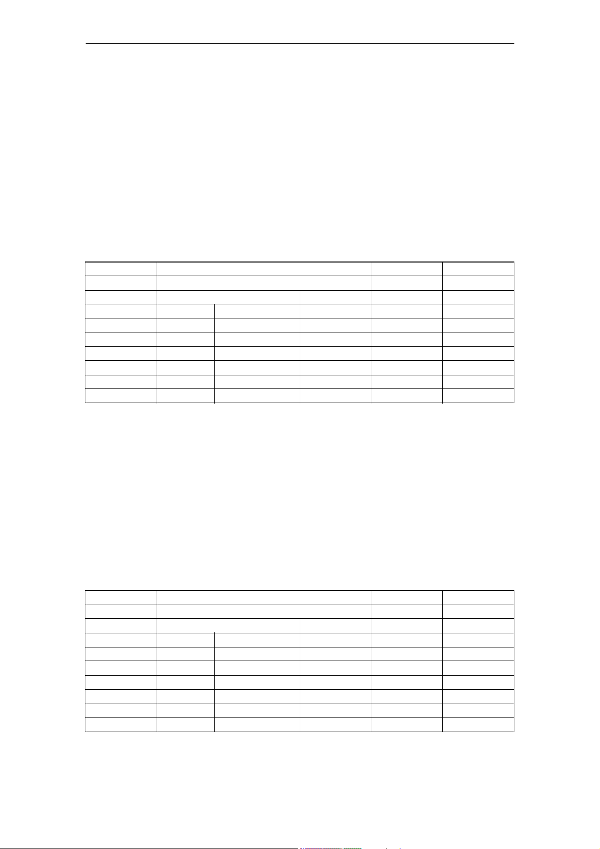
06/2007 Machine Data
Generale maschine data
Bit 0 = 1:
The D or DL number is not transferred to the replacement subprogram if the
following conditions are fulfilled: $MC_TOOL_CHANGE_MODE = 1 Programming
D/DL with T or M function with which the tool change cycle is called, in a
part program line.
Bit 1 = 0
Execution of the replacement subprogram at end of block (default value)
Bit 1 = 1
Execution of the replacement subprogram at block start
Bit 2 = 0:
Execution of the replacement subprogram according to the settin of bit 1
Bit 2 = 1:
Execution of the replacement subprogram at block start and at end of block.
10735 JOG_MODE_MASK EXP, N01 -
- Enable JOG in automatic DWORD POWER ON
-
--0 00x17/2
802d-cu3 - - - - 2/2
802d-ng2 - - - - 2/2
802d-ng3 - - - - 2/2
802d-tm1 - - - - 2/2
802d-tm2 - - - - 2/2
802d-tm3 - - - - 2/2
Description:
Bit 0:
Enables JOG in automatic.
JOG is enabled in automatic when all channels in the mode group are in the
RESET state and no channel of the DRF mode group has been selected. The
mode group changes internally to JOG with the +/- key and the handwheel,
and the axis moves. After the JOG motion has ended, a change back to AUTO
is also made internally.
Bits 1-31:
Currently unassigned.
10760 G53_TOOLCORR N12 FBFA
- Method of operation of G53, G153 and SUPA BOOLEAN POWER ON
-
--FALSE--7/2
802d-cu3 - - - - 2/2
802d-ng2 - - - - 2/2
802d-ng3 - - - - 2/2
802d-tm1 - - - - 2/2
802d-tm2 - - - - 2/2
802d-tm3 - - - - 2/2
©Siemens AG 2007 All Rights Reserved
SINUMERIK 802D sl, Parameter Manual, 06/2007 Edition
2-45
Page 46

Machine Data 06/2007
Generale maschine data
Description:
With this MD you define whether tool length offset and tool radius offset are
also to be suppressed with language commands G53, G153 and SUPA
0: G53,G153 and SUPA cause block-by-block suppression of zero offsets. The
active tool length offset and tool radius offset remain active.
1: G53,G153 and SUPA cause block-by-block suppression of zero offsets, active
tool length offset and tool radius offset.
10804 EXTERN_M_NO_SET_INT EXP, N12 FBFA
- M function to activate ASUB DWORD POWER ON
-
--96 --7/2
802d-cu3 - - - - 1/1
802d-ng2 - - - - -1/802d-ng3 - - - - -1/802d-tm1 - - - - 1/1
802d-tm2 - - - - 1/1
802d-tm3 - - - - 1/1
Description:
M function number used to activate an interrupt program (ASUB) in ISO2/3 mode.
The interrupt program is always started by the 1st high-speed input of the
numerical control.
The M number defined in the machine data replaces M96 in external language
mode.
Restrictions: Refer to machine data 10715: $MN_M_NO_FCT_CYCLE
Related to:
$MN_M_NO_FCT_EOP,
$MN_M_NO_FCT_CYCLE,
$MC_SPIND_RIGID_TAPPING_M_NR,
$MC_AUXFU_ASSOC_M0_VALUE
For external language mode:
$MN_EXTERN_M_NO_MAC_CYCLE,
$MN_EXTERN_M_NO_SET_INT
$MN_EXTERN_M_NO_DISABLE_INT,
$MN_EXTERN_CHAN_SYNC_M_NO_MIN,
$MN_EXTERN_CHAN_SYNC_M_NO_MAX
$MC_EXTERN_RIGID_TAPPING_M_NR
For nibbling:
$MC_NIBBLE_PUNCH_CODE
2-46
SINUMERIK 802D sl, Parameter Manual, 06/2007 Edition
©Siemens AG 2007 All Rights Reserved
Page 47

06/2007 Machine Data
Generale maschine data
10806 EXTERN_M_NO_DISABLE_INT EXP, N12 FBFA
- M function to deactivate ASUB DWORD POWER ON
-
--97 --7/2
802d-cu3 - - - - 1/1
802d-ng2 - - - - -1/802d-ng3 - - - - -1/802d-tm1 - - - - 1/1
802d-tm2 - - - - 1/1
802d-tm3 - - - - 1/1
Description:
M function number used to deactivate an interrupt program (ASUB) in ISO2/3
mode.
The M number defined in the machine data replaces M97 in external language
mode.
Restrictions: refer to machine data 10715 $MN_M_NO_FCT_CYCLE
$MN_M_NO_FCT_EOP,
$MN_M_NO_FCT_CYCLE,
$MC_SPIND_RIGID_TAPPING_M_NR,
$MC_AUXFU_ASSOC_M0_VALUE
For external language mode:
$MN_EXTERN_M_NO_MAC_CYCLE,
$MN_EXTERN_M_NO_SET_INT
$MN_EXTERN_M_NO_DISABLE_INT,
$MN_EXTERN_CHAN_SYNC_M_NO_MIN,
$MN_EXTERN_CHAN_SYNC_M_NO_MAX
$MC_EXTERN_RIGID_TAPPING_M_NR
For nibbling:
$MC_NIBBLE_PUNCH_CODE
10808 EXTERN_INTERRUPT_BITS_M96 EXP, N12 FBFA
- Activate interrupt program (ASUB) DWORD POWER ON
-
--0 --7/2
802d-cu3 - - - - 1/1
802d-ng2 - - - - -1/802d-ng3 - - - - -1/802d-tm1 - - - - 1/1
802d-tm2 - - - - 1/1
802d-tm3 - - - - 1/1
Description:
Setting the various bits can influence the processing of the interrupt routine
activated by M96 P...
©Siemens AG 2007 All Rights Reserved
SINUMERIK 802D sl, Parameter Manual, 06/2007 Edition
2-47
Page 48

Machine Data 06/2007
Generale maschine data
Bit 0 = 0,
No interrupt program possible, M96/M97 are normal M functions
Bit 0 = 1,
Using M96/M97 to activate an interrupt program is allowed
Bit 1 = 0,
Continue processing part program at the final position of the next block
after the interrupt block
Bit 1 = 1,
Continue processing part program from interrupt position
Bit 2 = 0,
The interrupt signal immediately interrupts the current block and starts
the interrupt routine
Bit 2 = 1,
The interrupt routine will not be started until the end of the block
Bit 3 = 0,
Interrupt machining cycle at an interupt signal
Bit 3 = 1,
Do not start interrupt program until the end of a machining cycle.
10810 EXTERN_MEAS_G31_P_SIGNAL EXP, N12 FBFA
- Config. of measuring inputs for G31 P.. BYTE POWER ON
-
- 41 037/2
802d-cu3 - - - - 2/2
802d-ng2 - - - - -1/802d-ng3 - - - - -1/802d-tm1 - - - - 2/2
802d-tm2 - - - - 2/2
802d-tm3 - - - - 2/2
Description:
This machine data defines the assignment of measurement inputs 1 and 2 to the
P numbers programmed with G31 P1 ( - P4). The machine data is bit-coded. Only
bits 0 and 1 are evaluated. For example, if bit 0 = 1 in
$MN_EXTERN_MEAS_G31_P_SIGNAL[1] the 1st measurement input is activated with
G31 P2. If $MN_EXTERN_MEAS_G31_P_SIGNAL[3]=2, the 2nd measurement input is
activated with G31 P4.
Bit 0: = 0, Do not evaluate measurement input 1 with G31 P1 (- P4)
Bit 0: = 1, Activate measurement input 1 with G31 P1 (- P4)
Bit 1: = 0, Do not evaluate measurement input 2 with G31 P1 (- P4)
Bit 1: = 1, Activate measurement input 2 with G31 P1 (- P4)
10812 EXTERN_DOUBLE_TURRET_ON EXP, N12 FBFA
- Double turret with G68 BOOLEAN POWER ON
-
--FALSE--7/2
802d-cu3 - - - - 2/2
802d-ng2 - - - - -1/802d-ng3 - - - - -1/802d-tm1 - - - - 2/2
802d-tm2 - - - - 2/2
802d-tm3 - - - - 2/2
2-48
SINUMERIK 802D sl, Parameter Manual, 06/2007 Edition
©Siemens AG 2007 All Rights Reserved
Page 49

06/2007 Machine Data
Generale maschine data
Description:
This machine data is used to determine whether double-slide machining (channel
synchronization for 1st and 2nd channel) is to be started using G68 or whether
the second tool of a double turret (= two closely-linked tools at a distance
defined in the setting data $SC_EXTERN_DOUBLE_TURRET_DIST) is to be activated.
FALSE:
Channel synchronization for double-slide machining
TRUE:
Load 2nd tool of a double turret (that is, activate
$SC_EXTERN_DOUBLE_TURRET_DISTANCE as additive zero offset and mirroring
around Z axis)
10814 EXTERN_M_NO_MAC_CYCLE EXP, N12 FBFA
- Macro call via M function DWORD POWER ON
-
-10-1 --7/2
802d-cu3 - - - - 2/2
802d-ng2 - - - - -1/802d-ng3 - - - - -1/802d-tm1 - - - - 2/2
802d-tm2 - - - - 2/2
802d-tm3 - - - - 2/2
Description:
A macro is called with this M number.
The name of the subprogram is stated in $MN_EXTERN_M_NO_MAC_CYCLE_NAME[n].
If the M function specified with $MN_EXTERN_M_NO_MAC_CYCLE[n] is programmed in
a part program block, the subprogram defined in EXTERN_M_NO_MAC_CYCLE_NAME[n]
is started. All addresses programmed in the block are written into the
corresponding variables.
If the M function is programmed again in the subprogram, the replacement by a
subprogram call does not take place any more.
$MN_EXTERN_M_NO_MAC_CYCLE[n] is only active in the external language mode
G291.
The subprograms configured with $MN_EXTERN_M_NO_MAC_CYCLE_NAME[n] must not be
active simultaneously in a block (part program line), i.e. maximally one M
function replacement can become active in a block. Neither an M98 nor a modal
subprogram call may be programmed in the block with the M function
replacement.
Subprogram return and the part program end arealso not permitted. Alarm 14016
is issued in case of a conflict. Restrictions: see machine data 10715:
$MN_M_NO_FCT_CYCLE
©Siemens AG 2007 All Rights Reserved
SINUMERIK 802D sl, Parameter Manual, 06/2007 Edition
2-49
Page 50

Machine Data 06/2007
Generale maschine data
Related to:
$MN_M_NO_FCT_EOP,
$MN_M_NO_FCT_CYCLE,
$MC_SPIND_RIGID_TAPPING_M_NR,
$MC_AUXFU_ASSOC_M0_VALUE
For external language mode:
$MN_EXTERN_M_NO_MAC_CYCLE,
$MN_EXTERN_M_NO_SET_INT
$MN_EXTERN_M_NO_DISABLE_INT,
$MN_EXTERN_CHAN_SYNC_M_NO_MIN,
$MN_EXTERN_CHAN_SYNC_M_NO_MAX
$MC_EXTERN_RIGID_TAPPING_M_NR
For nibbling:
$MC_NIBBLE_PUNCH_CODE
10815 EXTERN_M_NO_MAC_CYCLE_NAME EXP, N12 FBFA
- Name of subroutine for M function macro call STRING POWER ON
-
-10 --7/2
802d-cu3 - - - - 2/2
802d-ng2 - - - - -1/802d-ng3 - - - - -1/802d-tm1 - - - - 2/2
802d-tm2 - - - - 2/2
802d-tm3 - - - - 2/2
Description:
Name of the subprogram started by a call via the M function defined by
$MN_EXTERN_M_NO_MAC_CYCLE[n].
10816 EXTERN_G_NO_MAC_CYCLE EXP, N12 FBFA
- Macro call via G function DOUBLE POWER ON
-
-50-1. --7/2
802d-cu3 - - - - 2/2
802d-ng2 - - - - -1/802d-ng3 - - - - -1/802d-tm1 - - - - 2/2
802d-tm2 - - - - 2/2
802d-tm3 - - - - 2/2
Description:
G number for calling a macro.
The name of the subprogram is stated in $MN_EXTERN_G_NO_MAC_CYCLE_NAME[n].
If the G function specified with $MN_EXTERN_G_NO_MAC_CYCLE[n] is programmed in
a part program block, the subprogram defined in EXTERN_M_NO_MAC_CYCLE_NAME[n]
is started. All addresses programmed in the block are written in the
corresponding $C_xx variables.
2-50
SINUMERIK 802D sl, Parameter Manual, 06/2007 Edition
©Siemens AG 2007 All Rights Reserved
Page 51

06/2007 Machine Data
Generale maschine data
No subprogram call is executed if a subprogram call is already active via an
M/G macro or an M replacement. If a standard G function is programmed in this
case, this code is executed. Otherwise, alarm 12470 is issued.
$MN_EXTERN_G_NO_MAC_CYCLE[n] is only active in the external language mode
G291.
Only a single subprogram call may be included in a block. This means that only
a single M/G function replacement may be programmed in a block and no
additional subprogram (M98) or cycle call may be included in the block.
Furthermore, a subprogram return and a part program end are not permitted in
the same block.
Alarm 14016 is issued in case of a conflict.
10817 EXTERN_G_NO_MAC_CYCLE_NAME EXP, N12 FBFA
- Name of subroutine for G function macro call STRING POWER ON
-
-50 --7/2
802d-cu3 - - - - 2/2
802d-ng2 - - - - -1/802d-ng3 - - - - -1/802d-tm1 - - - - 2/2
802d-tm2 - - - - 2/2
802d-tm3 - - - - 2/2
Description:
Name of the subprogram started by call via the G function defined by
$MN_EXTERN_G_NO_MAC_CYCLE[n].
10818 EXTERN_INTERRUPT_NUM_ASUP EXP, N12 FBFA
- Interrupt number for ASUP start (M96) BYTE POWER ON
-
- -1 187/2
802d-cu3 - - - - 1/1
802d-ng2 - - - - -1/802d-ng3 - - - - -1/802d-tm1 - - - - 1/1
802d-tm2 - - - - 1/1
802d-tm3 - - - - 1/1
Description:
Number of the interrupt input starting an asynchronous subprogram activated in
ISO mode. (M96 <program number>)
©Siemens AG 2007 All Rights Reserved
SINUMERIK 802D sl, Parameter Manual, 06/2007 Edition
2-51
Page 52

Machine Data 06/2007
Generale maschine data
10820 EXTERN_INTERRUPT_NUM_RETRAC EXP, N12 FBFA
- Interrupt number for rapid retraction (G10.6) BYTE POWER ON
-
- -2 187/2
802d-cu3 - - - - 2/2
802d-ng2 - - - - -1/802d-ng3 - - - - -1/802d-tm1 - - - - 2/2
802d-tm2 - - - - 2/2
802d-tm3 - - - - 2/2
Description:
Number of the interrupt input triggering rapid retraction to the position
programmed with G10.6 in ISO mode.
10880 MM_EXTERN_CNC_SYSTEM N01, N12 FBFA
- Definition of the control system to be adapted DWORD POWER ON
-
- -1 137/2
802d-cu3 - - - - 2/2
802d-ng2 - - - - -1/802d-ng3 - - - - -1/802d-tm1 - - - - 2/2
802d-tm2 - - - - 2/2
802d-tm3 - - - - 2/2
Description:
Definition of the external CNC system whose part programs are to be executed
on the SINUMERIK control in addition to SINUMERIK code (ISO_1):
1: ISO_2: System Fanuc0 milling (from software version 5.1)
2: ISO_3: System Fanuc0 turning (from P5.2)
3: External language via OEM application (from software version 6.2)
10881 MM_EXTERN_GCODE_SYSTEM N01, N12 FBFA
- ISO_3 Mode: GCodeSystem DWORD POWER ON
-
- -0 027/2
802d-cu3 - - - - 2/2
802d-ng2 - - - - -1/802d-ng3 - - - - -1/802d-tm1 - - - - 2/2
802d-tm2 - - - - 2/2
802d-tm3 - - - - 2/2
2-52
SINUMERIK 802D sl, Parameter Manual, 06/2007 Edition
©Siemens AG 2007 All Rights Reserved
Page 53
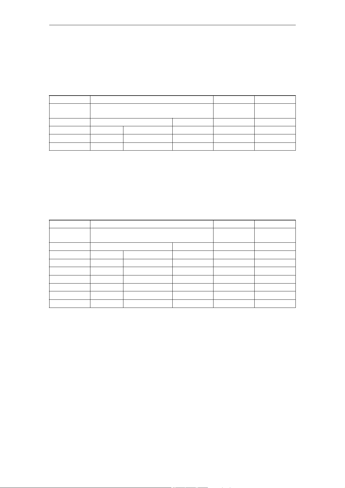
06/2007 Machine Data
Generale maschine data
Description:
Definition of the GCodeSystem to be actively executed in ISO_3 Mod (turning):
Value = 0 : ISO_3: Code system B
Value = 1 : ISO_3: Code system A
Value = 2 : ISO_3: Code system C
10882 NC_USER_EXTERN_GCODES_TAB N12 FBFA
- List of user-specific G commands of an external NC
language
-
-60 --2/2
802d-ng2 - - - - -1/802d-ng3 - - - - -1/-
Description:
List of G commands of external NC languages which have been reconfigured by
the user.
The implemented G commands are to be taken from the current Siemens
documentation for this programming language.
The list is structured as follows:
Even address: G command to be changed
Subsequent odd address: New G command
Only G codes can be reconfigured, e.g.: G20, G71.
STRING POWER ON
10884 EXTERN_FLOATINGPOINT_PROG N12 FBFA
- Evaluation of programmed values without decimal
point
-
--TRUE--7/2
802d-cu3 - - - - 2/2
802d-ng2 - - - - -1/802d-ng3 - - - - -1/802d-tm1 - - - - 2/2
802d-tm2 - - - - 2/2
802d-tm3 - - - - 2/2
Description:
This MD defines how programmed values without a decimal point are evaluated:
0: Values without a decimal point are interpreted in internal units. For
example, X1000 = 1 mm (for 0.001 mm input resolution) X1000.0 = 1000 mm
1: Values without decimal point are interpreted as mm, inch or degrees. For
example, X1000 = 1000 mm X1000.0 = 1000 mm
Related to:
EXTERN_INCREMENT_SYSTEM
BOOLEAN POWER ON
©Siemens AG 2007 All Rights Reserved
SINUMERIK 802D sl, Parameter Manual, 06/2007 Edition
2-53
Page 54

Machine Data 06/2007
Generale maschine data
10886 EXTERN_INCREMENT_SYSTEM N12 FBFA
- Incremental system in external language mode BOOLEAN POWER ON
-
--FALSE--7/2
802d-cu3 - - - - 2/2
802d-ng2 - - - - -1/802d-ng3 - - - - -1/802d-tm1 - - - - 2/2
802d-tm2 - - - - 2/2
802d-tm3 - - - - 2/2
Description:
This machine data is active for external programming languages, that is if MD
18800: MM_EXTERN_LANGUAGE = 1.
This machine data specifies which incremental system is active:
0: Incremental system IS-B = 0.001 mm/degree
= 0.0001 inch
1: Incremental system IS-C = 0.0001 mm/degree
= 0.00001 inch
Related to:
EXTERN_FLOATINGPOINT_PROG
10888 EXTERN_DIGITS_TOOL_NO N12 FBFA
- Digits for T number in ISO mode BYTE POWER ON
-
- -2 087/2
802d-cu3 - - - - 2/2
802d-ng2 - - - - -1/802d-ng3 - - - - -1/802d-tm1 - - - - 2/2
802d-tm2 - - - - 2/2
802d-tm3 - - - - 2/2
Description:
This machine data is only active when $MN_MM_EXTERN_CNC_SYSTEM = 2.
Number of digits of the tool number in the programmed T word.
From the programmed T word, the number of leading digits specified in
$MN_EXTERN_DIGITS_TOOL_NO are interpreted as the tool number.
The following digits address the offset memory.
2-54
SINUMERIK 802D sl, Parameter Manual, 06/2007 Edition
©Siemens AG 2007 All Rights Reserved
Page 55

06/2007 Machine Data
Generale maschine data
10890 EXTERN_TOOLPROG_MODE N12 FBFA
- Tool change programming for external language DWORD POWER ON
-
--0 --7/2
802d-cu3 - - - - 2/2
802d-ng2 - - - - -1/802d-ng3 - - - - -1/802d-tm1 - - - - 2/2
802d-tm2 - - - - 2/2
802d-tm3 - - - - 2/2
Description:
Configuration for programming the tool change in an external programming
language:
Bit0=0:
Only active if $MN_MM_EXTERN_CNC_SYSTEM =2: The tool number and offset
number are programmed in the T word. $MN_DIGITS_TOOLNO defines the number
of leading digits that the tool number generates.
Example:
$MN_DIGITS_TOOLNO = 2
T=1234 ; Tool number 12,
; Offset number 34
Bit0=1:
Only active if $MN_MM_EXTERN_CNC_SYSTEM =2: Only the tool number is
programmed in the T word. Offset number = Tool number. $MN_DIGITS_TOOLNO is
irrelevant.
Example:
T=12 ; Tool number 12
; Offset number 12
Bit1=0:
Only active if $MN_MM_EXTERN_CNC_SYSTEM =2: A leading 0 is added if the
number of digits programmed in the T word is the same as that in
$MN_EXTERN_DIGITS_TOOL_NO.
Bit1=1:
Only active if $MN_MM_EXTERN_CNC_SYSTEM =2: If the number of digits
programmed in the T word is equal to the number of digits defined in
$MN_EXTERN_DIGITS_TOOL_NO, the programmed number is both the offset number
and the tool number
Bit2=0:
Only active if $MN_MM_EXTERN_CNC_LANGUAGE =2: ISO T offset selection only
with D (Siemens cutting edge number)
Bit2=1:
Only active if $MN_MM_EXTERN_CNC_LANGUAGE =2: ISO T offset selection only
with H ($TC_DPH[t,d])
Bit3=0:
Only active if $MN_MM_EXTERN_CNC_SYSTEM =2: Each H number is only allowed
once in each TOA, except H=0. If bit3 1 -> 0 is set, no H number may occur
more than once in a TO unit. Otherwise an alarm will be issued at the next
restart.
©Siemens AG 2007 All Rights Reserved
SINUMERIK 802D sl, Parameter Manual, 06/2007 Edition
2-55
Page 56

Machine Data 06/2007
Generale maschine data
Bit3=1:
Only active if $MN_MM_EXTERN_CNC_SYSTEM =2: Each H number is only allowed
more than once in each TOA.
Bit6=0:
Only active if MN_MM_EXTERN_CNC_SYSTEM =1: Tool length cannot be selected
under address H
Bit6=1:
Only active if MN_MM_EXTERN_CNC_SYSTEM =1: Tool length selected under
address H
Bit7=0:
Only active if MN_MM_EXTERN_CNC_SYSTEM =1: Tool length cannot be selected
under address D
Bit7=1:
Only active if MN_MM_EXTERN_CNC_SYSTEM =1: Tool length selected under
address D.
Selection under address D or H is possible if bits 6 and 7 have been set.
10900 INDEX_AX_LENGTH_POS_TAB_1 N09 T1
- Number of positions for indexing axis table 1 DWORD RESET
-
- - 0 0 60 7/2
802d-cu3 - - - - 2/2
802d-ng2 - - - - 2/2
802d-ng3 - - - - 2/2
802d-tm1 - - - - 0/0
802d-tm2 - - - - 2/2
802d-tm3 - - - - 2/2
Description:
The indexing position table is used to assign the axis positions in the valid
unit of measurement (mm, inches or degrees) to the indexing positions [n] on
the indexing axis. The number of indexing positions used in table 1 is defined
by the MD: INDEX_AX_LENGTH_POS_TAB_1.
These indexing positions must contain valid values in table 1. Any indexing
positions in the table above the number specified in the machine data are
ignored. Up to 60 indexing positions (0 to 59) can be entered in the table.
Table length = 0 means that the table is not evaluated. If the length is not
equal to 0, then the table must be assigned to an axis with the MD:
INDEX_AX_ASSIGN_POS_TAB.
If the indexing axis is defined as a rotary axis (MD: IS_ROT_AX = "1") with
modulo 360° (MD: ROT_IS_MODULO = "1"), the machine data defines the last
indexing position after which, with a further traversing movement in the
positive direction, the indexing positions begin again at 1 .
Special cases:
Alarm 17090 "Value violates upper limit" if values over 60 are entered in
the MD: INDEX_AX_LENGTH_POS_TAB_1.
2-56
SINUMERIK 802D sl, Parameter Manual, 06/2007 Edition
©Siemens AG 2007 All Rights Reserved
Page 57

06/2007 Machine Data
Generale maschine data
Related to:
MD: INDEX_AX_ASSIGN_POS_TAB (axis is an indexing axis)
MD: INDEX_AX_POS_TAB_1 (indexing position table 1)
MD: IS_ROT_AX (rotary axis)
MD: ROT_IS_MODULO (modulo conversion for rotary axis)
10910 INDEX_AX_POS_TAB_1 N09 T1
mm/inch,
degrees
-
-600. --7/2
802d-cu3 - - - - 2/2
802d-ng2 - - - - 2/2
802d-ng3 - - - - 2/2
802d-tm1 1 - - - 0/0
802d-tm2 - - - - 2/2
802d-tm3 - - - - 2/2
Description:
The indexing position table is used to assign the axis positions in the valid
unit of measurement (mm, inches or degrees) to the indexing positions [n] on
the indexing axis.
[n] = indexing for the entry of the indexing positions in the indexing
position table.
Range: 0 y n x 59, where 0 is the 1st indexing position and 59 corresponds to
the 60th indexing position.
Indexing position table 1 DOUBLE RESET
Note.
Programming with the absolute indexing position (e.g. CAC) starts with
indexing position 1. This corresponds to the indexing position with
indexing n = 0 in the indexing position table.
The following should be noted when entering the indexing positions:
- Up to 60 different indexing positions can be stored in the table.
- The 1st entry in the table corresponds to indexing position 1; the nth entry
corresponds to indexing position n.
- The indexing positions must be entered in the table in ascending order
(starting with the negative to the positive traversing range) with no gaps
between the entries. Consecutive position values must not be identical.
- If the indexing axis is defined as a rotary axis (MD: IS_ROT_AX = "1") with
modulo 360° (MD: ROT_IS_MODULO = "1"), then the position values are limited
to a range of 0° x pos. < 360°.
The number of indexing positions used in the table is defined by the MD:
INDEX_AX_LENGTH_POS_TAB_1.
Entering the value 1 in the axial machine data: INDEX_AX_ASSIGN_POS_TAB
assigns indexing position table 1 to the current axis.
Special cases:
Alarm 17020 "illegal array index" if over 60 positions are entered in the
table.
©Siemens AG 2007 All Rights Reserved
SINUMERIK 802D sl, Parameter Manual, 06/2007 Edition
2-57
Page 58

Machine Data 06/2007
Generale maschine data
Related to:
MD: INDEX_AX_ASSIGN_POS_TAB (axis is an indexing axis)
MD: INDEX_AX_LENGTH_POS_TAB_1 (no. of indexing positions used in table 1)
MD: IS_ROT_AX (rotary axis)
MD: ROT_IS_MODULO (modulo conversion for rotary axis)
10920 INDEX_AX_LENGTH_POS_TAB_2 N09 T1
- Number of positions for indexing axis table 2 DWORD RESET
-
- - 0 0 60 7/2
802d-cu3 - - - - 2/2
802d-ng2 - - - - 2/2
802d-ng3 - - - - 2/2
802d-tm1 - - - - 0/0
802d-tm2 - - - - 2/2
802d-tm3 - - - - 2/2
Description:
The indexing position table is used to assign the axis positions in the valid
unit of measurement (mm, inches or degrees) to the indexing positions [n] on
the indexing axis. The number of indexing positions used in table 2 is defined
by the MD: INDEX_AX_LENGTH_POS_TAB_2.
These indexing positions in table 2 must contain valid values. Any indexing
positions in the table above the number specified in the machine data are
ignored.
Up to 60 indexing positions (0 to 59) can be entered in the table.
Table length = 0 means that the table is not evaluated. If the length is not
equal to 0, the table must be assigned to an axis with the MD:
INDEX_AX_ASSIGN_POS_TAB.
If the indexing axis is defined as a rotary axis (MD: IS_ROT_AX = "1") with
modulo 360° (MD: ROT_IS_MODULO = "1"), the machine data defines the last
indexing position after which, with a further traversing movement in the
positive direction, the indexing positions begin again at 1.
Not relevant for tool magazines (revolvers, chain magazines)
Special cases:
Alarm 17090 "Value violates upper limit" if a value over 60 is entered in
the MD:INDEX_AX_LENGTH_POS_TAB_2.
Related to:
MD: INDEX_AX_ASSIGN_POS_TAB (axis is an indexing axis)
MD: INDEX_AX_POS_TAB_2 (indexing position table 2)
MD: IS_ROT_AX (rotary axis)
MD: ROT_IS_MODULO (modulo conversion for rotary axis)
2-58
SINUMERIK 802D sl, Parameter Manual, 06/2007 Edition
©Siemens AG 2007 All Rights Reserved
Page 59

06/2007 Machine Data
Generale maschine data
10930 INDEX_AX_POS_TAB_2 N09 T1
mm/inch,
degrees
-
-600. --7/2
802d-cu3 - - - - 2/2
802d-ng2 - - - - 2/2
802d-ng3 - - - - 2/2
802d-tm1 1 - - - 0/0
802d-tm2 - - - - 2/2
802d-tm3 - - - - 2/2
Description:
The indexing position table is used to assign the axis positions in the valid
unit of measurement (mm, inches or degrees) to the indexing positions [n] on
the indexing axis.
[n] = indexing for the entry of the indexing positions in the indexing
position table.
Range: 0 y n x 59, where 0 is the 1st indexing position and 59 corresponds to
the 60th indexing position.
Indexing position table 2 DOUBLE RESET
Note:
Programming with the absolute indexing position (e.g. CAC) starts with
indexing position 1. This corresponds to the indexing position with
indexing n = 0 in the table.
The following should be noted when entering the indexing positions:
- Up to 60 different indexing positions can be stored in the table.
- The 1st entry in the table corresponds to indexing position 1; the nth entry
corresponds to indexing position n.
- The indexing positions should be entered in the table in ascending order
(starting with the negative to the positive traversing range) with no gaps
between the entries. Consecutive position values must not be identical.
- If the indexing axis is defined as a rotary axis (MD: IS_ROT_AX = "1") with
modulo 360° (MD: ROT_IS_MODULO = "1"), then the position values are limited
to a range of 0° x pos. < 360°.
The number of indexing positions used in the table is defined by the MD:
INDEX_AX_LENGTH_POS_TAB_2.
Entering the value 1 in the axial machine data: INDEX_AX_ASSIGN_POS_TAB
assigns indexing position table 1 to the current axis.
Special cases:
Alarm 17020 "illegal array index" if over 60 positions are entered in the
table.
Related to:
MD: INDEX_AX_ASSIGN_POS_TAB (axis is an indexing axis)
MD: INDEX_AX_LENGTH_POS_TAB_2 (no. of indexing positions used in table 2)
MD: IS_ROT_AX (rotary axis)
MD: ROT_IS_MODULO (modulo conversion for rotary axis)
©Siemens AG 2007 All Rights Reserved
SINUMERIK 802D sl, Parameter Manual, 06/2007 Edition
2-59
Page 60

Machine Data 06/2007
Generale maschine data
11100 AUXFU_MAXNUM_GROUP_ASSIGN N01, N07, N02 H2
- Number of auxiliary functions distributed among the
AUXFU groups
-
- - 1 1 255 7/2
802d-cu3 - 1 - - 2/2
802d-ng2 - 1 - - 2/2
802d-ng3 - 1 - - 2/2
802d-tm1 - 1 - - 2/2
802d-tm2 - 1 - - 2/2
802d-tm3 - 1 - - 2/2
Description:
The number of the auxiliary functions that have been distributed to the groups
must be entered in the MD. This number only includes the customer-specific
auxiliary functions, not the predefined auxiliary functions.
Anwendungsbeispiel:
related to:
MD 22010: AUXFU_ASSIGN_TYPE [n] (auxiliary function type)
DWORD POWER ON
11160 ACCESS_EXEC_CST N01 -
- Execution right for /_N_CST_DIR BYTE POWER ON
-
--7 --7/2
802d-cu3 - - - - 2/2
802d-ng2 - - - - 2/2
802d-ng3 - - - - 2/2
802d-tm1 - - - - 2/2
802d-tm2 - - - - 2/2
802d-tm3 - - - - 2/2
Description:
Execution right assigned to the program stored in directory /_N_CST_DIR :
Value 0: Siemens password
Value 1: Machine OEM password
Value 2: Password of startup engineer, service
Value 3: End user password
Value 4: Keyswitch position 3
Value 5: Keyswitch position 2
Value 6: Keyswitch position 1
Value 7: Keyswitch position 0
Machine data can only be written with values 0 and 1, and with the
corresponding password also active.
2-60
SINUMERIK 802D sl, Parameter Manual, 06/2007 Edition
©Siemens AG 2007 All Rights Reserved
Page 61

06/2007 Machine Data
Generale maschine data
11161 ACCESS_EXEC_CMA N01 -
- Execution right for /_N_CMA_DIR BYTE POWER ON
-
--7 --7/2
802d-cu3 - - - - 2/2
802d-ng2 - - - - 2/2
802d-ng3 - - - - 2/2
802d-tm1 - - - - 2/2
802d-tm2 - - - - 2/2
802d-tm3 - - - - 2/2
Description:
Execution right assigned to the programs stored in directory /_N_CMA_DIR :
Value 0: Siemens password
Value 1: Machine OEM password
Value 2: Password of startup engineer, service
Value 3: End user password
Value 4: Keyswitch position 3
Value 5: Keyswitch position 2
Value 6: Keyswitch position 1
Value 7: Keyswitch position 0
Machine data can only be written with values 0 and 1, and with the
corresponding password also active.
11162 ACCESS_EXEC_CUS N01 -
- Execution right for /_N_CUS_DIR BYTE POWER ON
-
--7 --7/3
802d-cu3 - - - - 3/3
802d-ng2 - - - - 3/3
802d-ng3 - - - - 3/3
802d-tm1 - - - - 3/3
802d-tm2 - - - - 3/3
802d-tm3 - - - - 3/3
Description:
Execution right assigned to the programs stored in directory /_N_CUS_DIR :
Value 0: Siemens password
Value 1: Machine OEM password
Value 2: Password of startup engineer, service
Value 3: End user password
Value 4: Keyswitch position 3
Value 5: Keyswitch position 2
Value 6: Keyswitch position 1
Value 7: Keyswitch position 0
Machine data can only be written with values 0, 1 and 2, and with the
corresponding password also active.
©Siemens AG 2007 All Rights Reserved
SINUMERIK 802D sl, Parameter Manual, 06/2007 Edition
2-61
Page 62

Machine Data 06/2007
Generale maschine data
11165 ACCESS_WRITE_CST N01 -
- Write protection for directory /_N_CST_DIR DWORD POWER ON
-
---1 --7/2
802d-cu3 - - - - 2/2
802d-ng2 - - - - 2/2
802d-ng3 - - - - 2/2
802d-tm1 - - - - 2/2
802d-tm2 - - - - 2/2
802d-tm3 - - - - 2/2
Description:
Set write protection for cycle directory /_N_CST_DIR:
Assigned to the programs:
Value -1: Keep the value currently set
Value 0: Siemens password
Value 1: Machine OEM password
Value 2: Password of startup engineer, service
Value 3: End user password
Value 4: Keyswitch position 3
Value 5: Keyswitch position 2
Value 6: Keyswitch position 1
Value 7: Keyswitch position 0
The machine data can only be written with values 0 and 1, and with the
corresponding password also active.
11166 ACCESS_WRITE_CMA N01 -
- Write protection for directory /_N_CMA_DIR DWORD POWER ON
-
---1 --7/2
802d-cu3 - - - - 2/2
802d-ng2 - - - - 2/2
802d-ng3 - - - - 2/2
802d-tm1 - - - - 2/2
802d-tm2 - - - - 2/2
802d-tm3 - - - - 2/2
Description:
Set write protection for cycle directory /_N_CMA_DIR:
Assigned to the programs:
Value -1: Keep the value currently set
Value 0: Siemens password
Value 1: Machine OEM password
Value 2: Password of startup engineer, service
Value 3: End user password
Value 4: Keyswitch position 3
Value 5: Keyswitch position 2
Value 6: Keyswitch position 1
Value 7: Keyswitch position 0
The machine data can only be written with values 0 and 1, and with the
corresponding password also active.
2-62
SINUMERIK 802D sl, Parameter Manual, 06/2007 Edition
©Siemens AG 2007 All Rights Reserved
Page 63

06/2007 Machine Data
Generale maschine data
11167 ACCESS_WRITE_CUS N01 -
- Write protection for directory /_N_CUS_DIR DWORD POWER ON
-
---1 --7/3
802d-cu3 - - - - 2/2
802d-ng2 - - - - 2/2
802d-ng3 - - - - 2/2
802d-tm1 - - - - 3/3
802d-tm2 - - - - 3/3
802d-tm3 - - - - 3/3
Description:
Set write protection for cycle directory /_N_CUS_DIR:
Assigned to the programs:
Value -1: Keep the value currently set
Value 0: Siemens password
Value 1: Machine OEM password
Value 2: Password of startup engineer, service
Value 3: End user password
Value 4: Keyswitch position 3
Value 5: Keyswitch position 2
Value 6: Keyswitch position 1
Value 7: Keyswitch position 0
The machine data can only be written with values 0, 1 and 2, and with the
corresponding password also active.
11170 ACCESS_WRITE_SACCESS N01 -
- Write protection for _N_SACCESS_DEF BYTE POWER ON
-
--7 --7/2
802d-cu3 - - - - 2/2
802d-ng2 - - - - 2/2
802d-ng3 - - - - 2/2
802d-tm1 - - - - 2/2
802d-tm2 - - - - 2/2
802d-tm3 - - - - 2/2
Description:
Set write protection for definition file /_N_DEF_DIR/_N_SACCESS_DEF:
Value 0: Siemens password
Value 1: Machine OEM password
Value 2: Password of startup engineer, service
Value 3: End user password
Value 4: Keyswitch position 3
Value 5: Keyswitch position 2
Value 6: Keyswitch position 1
Value 7: Keyswitch position 0
The machine data can only be written with values 0 and 1, and with the
corresponding password also active.
©Siemens AG 2007 All Rights Reserved
SINUMERIK 802D sl, Parameter Manual, 06/2007 Edition
2-63
Page 64

Machine Data 06/2007
Generale maschine data
11171 ACCESS_WRITE_MACCESS N01 -
- Write protection for _N_MACCESS_DEF BYTE POWER ON
-
--7 --7/2
802d-cu3 - - - - 2/2
802d-ng2 - - - - 2/2
802d-ng3 - - - - 2/2
802d-tm1 - - - - 2/2
802d-tm2 - - - - 2/2
802d-tm3 - - - - 2/2
Description:
Set write protection for definition file /_N_DEF_DIR/_N_SACCESS_DEF:
Value 0: Siemens password
Value 1: Machine OEM password
Value 2: Password of startup engineer, service
Value 3: End user password
Value 4: Keyswitch position 3
Value 5: Keyswitch position 2
Value 6: Keyswitch position 1
Value 7: Keyswitch position 0
The machine data can only be written with values 0 and 1, and with the
corresponding password also active.
11172 ACCESS_WRITE_UACCESS N01 -
- Write protection for _N_UACCESS_DEF BYTE POWER ON
-
--7 --7/3
802d-cu3 - - - - 3/3
802d-ng2 - - - - 3/3
802d-ng3 - - - - 3/3
802d-tm1 - - - - 3/3
802d-tm2 - - - - 3/3
802d-tm3 - - - - 3/3
Description:
Set write protection for definition file /_N_DEF_DIR/_N_UACCESS_DEF:
Value 0: Siemens password
Value 1: Machine OEM password
Value 2: Password of startup engineer, service
Value 3: End user password
Value 4: Keyswitch position 3
Value 5: Keyswitch position 2
Value 6: Keyswitch position 1
Value 7: Keyswitch position 0
The machine data can only be written with values 0, 1 and 2, and with the
corresponding password also active.
2-64
SINUMERIK 802D sl, Parameter Manual, 06/2007 Edition
©Siemens AG 2007 All Rights Reserved
Page 65

06/2007 Machine Data
Generale maschine data
11210 UPLOAD_MD_CHANGES_ONLY N01, N05 IAD
- MD backup of changed MD only BYTE SOFORT
-
--0xFF--7/3
802d-cu3 - 0x0F - - 2/2
802d-ng2 - 0x0F - - 2/2
802d-ng3 - 0x0F - - 2/2
802d-tm1 - 0x0F - - 2/2
802d-tm2 - 0x0F - - 2/2
802d-tm3 - 0x0F - - 2/2
Description:
Selection of differential MD upload:
Bit0(LSB)Effectiveness of the differential upload for TEA files (machine data
files)
0: All data are output
1: only the values changed as compared to the compiled MD are output
Bit1 Effectiveness of the differential upload for INI files
0: All data are output
1: only the values changed as compared to the compiled MD are output
Bit2 change of a field element
0: complete arrays are output
1: only changed field elements of an array are output
Bit3 R parameter (for INI files only)
0: All R parameters are output
1: only R parameters unequal to '0' are output
Bit4 frames (for INI files only)
0: All frames are output
1: only frames are output which are not zero frames.
Bit5 tool data (cutting edge parameter) (for INI files only)
0: All tool data are output
1: only tool data unequal to '0' are output.
11240 PROFIBUS_SDB_NUMBER N01, N05 K4,FBU
- SDB1000 number DWORD POWER ON
-
-4-1 -172/2
802d-cu3 - 0,-1,0 - - -/802d-ng2 - 0,-1,0 - - -/802d-ng3 - 0,-1,0 - - -/802d-tm1 - 0,-1,0 - - -/802d-tm2 - 0,-1,0 - - -/802d-tm3 - 0,-1,0 - - -/-
Description:
BUS_SDB_NUMBER [0] = 0
Digital inputs and outputs via I/O modules (PP modules)
The assignment is provided via DIL switches. Max. 3 modules with the addresses
9, 8 and 7 are possible.
©Siemens AG 2007 All Rights Reserved
SINUMERIK 802D sl, Parameter Manual, 06/2007 Edition
2-65
Page 66

Machine Data 06/2007
Generale maschine data
PROFIBUS_SDB_NUMBER [2] = X
Number of the system module you are using for configuring the hardware I/Os.
SINUMERIK 802D sl offers the following options to choose from:
0: 2 SINAMICS drives with SLM
1: 3 SINAMICS drives with SLM
2: 4 SINAMICS drives with SLM
3: 5 SINAMICS drives with SLM
4: 3 SINAMICS drives with ALM
5: 4 SINAMICS drives with ALM
6: 5 SINAMICS drives with ALM
Note:
With the SDB reloaded from the toolbox, PROFIBUS_SDB_NUMBER[2] = 0 must be
set. This activates the module.
The machine data PROFIBUS_SDB_NUMBER[1] and PROFIBUS_SDB_NUMBER[3] are
reserved internally for Siemens.
11241 PROFIBUS_SDB_SELECT N01, N05 -
- SDB source selection DWORD POWER ON
-
- -0 032/2
Description:
With MD11240 > 0, SDBs are loaded directly from the directory:
MD11241=0: /siemens/sinumerik/sdb/...
MD11241=1: /addon/sinumerik/sdb/...
MD11241=2: /oem/sinumerik/sdb/...
MD11241=3: /user/sinumerik/sdb/...
11250 PROFIBUS_SHUTDOWN_TYPE EXP, N01 G3,FBU
- Profibus shutdown handling BYTE POWER ON
-
- -0 027/2
802d-cu3 - - - - 2/2
802d-ng2 - - - - 2/2
802d-ng3 - - - - 2/2
802d-tm1 - - - - 2/2
802d-tm2 - - - - 2/2
802d-tm3 - - - - 2/2
Description:
Handling of PROFIBUS when shutting down NCK (NCK reset)
Value 0:
The bus is shut down directly from cyclic operation, without 'prewarning'
Value 1:
When shutting down NCK, the PROFIBUS is changed to the CLEAR state for at
least 20 cycles. Then, it is shut down. If this is not possible on the
hardware side, the procedure described for value 2 is used instead.
2-66
SINUMERIK 802D sl, Parameter Manual, 06/2007 Edition
©Siemens AG 2007 All Rights Reserved
Page 67

06/2007 Machine Data
Generale maschine data
Value 2:
When shutting down NCK, the PROFIBUS is changed to a state where all drives
are sent a zero word as control word1 and control word2 (pseudoclear) for
at least 20 cycles. The bus itself remains in the Operate status.
11270 DEFAULT_VALUES_MEM_MASK N01 PGA
- Activation of default values for NC language elementsDWORD POWER ON
-
--0 --7/2
802d-cu3 - - - - 1/1
802d-ng2 - 1 - - -/802d-ng3 - 1 - - -/802d-tm1 - - - - 1/1
802d-tm2 - - - - 1/1
802d-tm3 - - - - 1/1
Description:
Activation of the function 'Memory for initialization values of
NC language elements'
Bit Hex. Meaning
value
------------------------------0: (LSB) 0x1 default values GUD
Meaning of the individual bits:
Bit 0 = 0:
The default values stated for the definition are not stored
Bit 0 = 1:
The default values stated for the definition are stored persistently. The
memory reserved via MD $MN_MM_GUD_VALUES_MEM is used for this purpose.
The memory reserved via $MN_MM_GUD_VALUES_MEM should be increased by the size
required for default values.
If this size cannot be determined, the memory should be doubled and
adaptations should be made later if required.
The stored default values can be restored, provided that the corresponding
programming (REDEF) has been performed.
11310 HANDWH_REVERSE N09 H1
- Threshold for change in handwheel direction BYTE POWER ON
-
--2 --7/2
802d-cu3 - - - - 2/2
802d-ng2 - - - - 2/2
802d-ng3 - - - - 2/2
802d-tm1 - - - - 2/2
802d-tm2 - - - - 2/2
802d-tm3 - - - - 2/2
©Siemens AG 2007 All Rights Reserved
SINUMERIK 802D sl, Parameter Manual, 06/2007 Edition
2-67
Page 68

Machine Data 06/2007
Generale maschine data
Description:
0:No immediate movement in the opposite direction
> 0:Immediate movement in the opposite direction if the handwheel is turned in
the opposite direction by at least the number of pulses indicated
11320 HANDWH_IMP_PER_LATCH N09 H1
- Handwheel pulses per detent position [handwheel
index]:
-
-61. --7/2
802d-cu3 - - - - 2/2
802d-ng2 - - - - 2/2
802d-ng3 - - - - 2/2
802d-tm1 - - - - 2/2
802d-tm2 - - - - 2/2
802d-tm3 - - - - 2/2
Description:
This adapts the connected handwheels to the control system.
The number of pulses generated by the handwheel for each handwheel detent
position is entered. The handwheel pulse weighting may be defined for each
connected handwheel (1 to 2) separately.
When adapted to the control, each handwheel detent position has the same
effect as one press of the traverse key in incremental jogging mode.
If a negative value is entered, the handwheel is active in the reverse
direction.
related to:
MD: JOG_INCR_WEIGHT (weighting of an increment of a machine axis for
INC/manual).
DOUBLE POWER ON
11346 HANDWH_TRUE_DISTANCE N01 FBMA
- Handwheel path or velocity values BYTE POWER ON
-
- -1 037/2
802d-cu3 - 0 - - 2/2
802d-ng2 - 0 - - 2/2
802d-ng3 - 0 - - 2/2
802d-tm1 - 0 - - 2/2
802d-tm2 - 0 - - 2/2
802d-tm3 - 0 - - 2/2
Description:
0: The settings from the handwheel are velocity settings. When the handwheel is
stationary, braking is realized along the shortest path.
1: The settings from the handwheel are distance settings. No pulses are lost.
Limiting the velocity to the maximum permissible value can cause the axes to
overtravel.
2: Effect as for value=0, however, with a longer braking travel when the
handwheel is stationary.
3: Effect as for value=1, however, with a longer braking travel when the
2-68
SINUMERIK 802D sl, Parameter Manual, 06/2007 Edition
©Siemens AG 2007 All Rights Reserved
Page 69

06/2007 Machine Data
Generale maschine data
handwheel is stationary.
related to:
11717 D_NO_FCT_CYCLE_NAME EXP, N12, N07 -
- Subroutine name for D function replacement STRING POWER ON
-
-- --7/2
802d-cu3 - - - - 2/2
802d-ng2 - - - - 2/2
802d-ng3 - - - - 2/2
802d-tm1 - - - - 2/2
802d-tm2 - - - - 2/2
802d-tm3 - - - - 2/2
Description:
Cycle name for replacement routine of the T function.
If a D function is programmed in a part program block, then, depending on
machine data $MN_T_NO_FCT_CYCLE_NAME, $MN_T_NO_FCT_CYCLE_MODE and
$MN_M_NO_FCT_CYCLE_PAR, the subprogram defined in D_NO_FCT_CYCLE_NAME is
called.
The programmed D number can be polled in the cycle via system variable $C_D /
$C_D_PROG.
$MN_D_NO_FCT_CYCLE_NAME is only active in Siemens mode (G290).
No more than one M/T/D function replacement can be active per part program
line.
A modal subprogram call must not be programmed in the block with the D
function replacement. Furthermore, neither subprogram return nor part program
end are allowed.
In the event of a conflict alarm 14016 is output.
13060 DRIVE_TELEGRAM_TYPE N04, N10 G2
- Default message frame type for drives connected to
PROFIBUS DP
-
-31102 --7/2
802d-cu3 - 116,102 - - 2/2
802d-ng2 - 116,102 - - 2/2
802d-ng3 - 116,102 - - 2/2
802d-tm1 - 116,102 - - 2/2
802d-tm2 - 116,102 - - 2/2
802d-tm3 - 116,102 - - 2/2
Description:
The message frame type:
102: must be specified for each drive. Standard message frame for SINAMICS
actual-value assignment
DWORD POWER ON
©Siemens AG 2007 All Rights Reserved
SINUMERIK 802D sl, Parameter Manual, 06/2007 Edition
2-69
Page 70

Machine Data 06/2007
Generale maschine data
103: SINAMICS- Spindle with second direct measuring system
Index [n] of the machine data has the following code: [drive index]:
n=0: Drive number 1
n=1: Drive number 2, etc.
13070 DRIVE_FUNCTION_MASK N04, N10 G2
- DP functions used DWORD POWER ON
-
-310 --7/2
802d-cu3 - 2,0 - - 2/2
802d-ng2 - 2,0 - - 2/2
802d-ng3 - 2,0 - - 2/2
802d-tm1 - 2,0 - - 2/2
802d-tm2 - 2,0 - - 2/2
802d-tm3 - 2,0 - - 2/2
Description:
Bit-coded mask for skipping the scope of available functions for PROFIBUS axes
expected from NCK.
Significance of set bits:
Bit 0:Deactivation of axial drive alarm display
Bit 1:Deactivation of 611U description file intermediate storage in the NCK
Bit 2:Deactivation of axial encoder driver parameter accesses
Bit 3:Deactivation of axial output driver parameter accesses
Bit 4:reserved (previously activation of DSC bits)
Bit 5:Deactivation of the 611U-specific drive parking (STW2.7/STA2.7)
Bit 6:Deactivation of the 611U-specific travel to fixed stop (STW2.8/STA2.8)
Bit 7:Deactivation of the 611U-specific motor switching int. (STW2.9 to 2.11)
Bit 8:Deactivation of the 611U-specific ramp block (STW1.11+13)
Bit 9:Deactivation of the 611U-specific function generator bits
(STW1.8/STA1.13)
Bit 10:Deactivation of the control of the holding brake (STW1.12 / STA2.5)
Bit 11:Deactivation of the effect of OFF2/OFF3 on "driveReady" (DB31, ...
DBX93.5)
Bit 14:Selection of non-cyclical communication 0 = DPT 1 = DPV1
Bit 15: Deactivation of the consistency check of the PROFIBUS telegram
configuration
The configuration of bits 4-8 which are new for SW 6.3 and higher allows an
adaptation of certain PROFIdrive profiles of non-standardized PROFIBUS control
or status bits of SIMODRIVE 611 universal. Bits 4 to 8 may have a different
significance in the default setting of external drives.
2-70
SINUMERIK 802D sl, Parameter Manual, 06/2007 Edition
©Siemens AG 2007 All Rights Reserved
Page 71

06/2007 Machine Data
Generale maschine data
13080 DRIVE_TYPE_DP EXP G2
- Drive type Profibus BYTE POWER ON
-
- 310 047/2
802d-cu3 - - - - 2/2
802d-ng2 - - - - 2/2
802d-ng3 - - - - 2/2
802d-tm1 - - - - 2/2
802d-tm2 - - - - 2/2
802d-tm3 - - - - 2/2
Description:
MD is relevant for drives at the PROFIBUS:
Drive type:
0: No drive or drive type unknown (default),
software-internally treated as:
1:FDD drive (SRM: Synchronous rotary drive)
2:MSD drive (ARM: Asynchronous rotary drive)
3:Linear drive
4:Analog drive (no automatic entry)
Note:
In general, the drive type is entered automatically with Siemens drives as
soon as the drives start operating.
With non-Siemens drives (at least with linear drives) the value must be
entered manually if automatic drive recognition is not possible.
13120 CONTROL_UNIT_LOGIC_ADDRESS N04, N10 -
- Logical address of SINAMICS CU DWORD POWER ON
-
- 7 0 0 8191 7/2
802d-cu3 - 6500,0 - - 1/1
802d-ng2 - 6500,0 - - 1/1
802d-ng3 - 6500,0 - - 1/1
802d-tm1 - 6500,0 - 1/1
802d-tm2 - 6500,0 - - 1/1
802d-tm3 - 6500,0 - - 1/1
Description:
Logical I/O address of a SINAMICS-CU (Control Unit) on the PROFIBUS-DP.
The cyclic DP communication with SINAMICS-CU is activated by taking over the
associated slot address from the STEP7 project. The onboard I/Os cannot be
accessed until after configuration.
©Siemens AG 2007 All Rights Reserved
SINUMERIK 802D sl, Parameter Manual, 06/2007 Edition
2-71
Page 72

Machine Data 06/2007
Generale maschine data
13150 SINAMICS_ALARM_MASK N04, N05 -
- Activate fault and warning buffer output for Sinamics DWORD SOFORT
-
--0x0 --7/2
802d-cu3 - - - - 1/1
802d-ng2 - - - - 1/1
802d-ng3 - - - - 1/1
802d-tm1 - - - - 1/1
802d-tm2 - - - - 1/1
802d-tm3 - - - - 1/1
Description:
Relevant to SINAMICS diagnostics:
Mask for displaying the SINAMICS DOS fault and warning buffers
Bit set:Alarms in this DO group are output
Bit not set:Alarms in this DO group are not output
BitHex. Meaning
value
==============================================================================
======
0: 0x1 Output faults of the Control Units
1: 0x2 Reserved
2: 0x4 Output faults of the Drive Controls
3: 0x8 Output faults of the Line Modules
4: 0x10 Output faults of the Terminal Boards
5: 0x20 Output faults of the Terminal Modules
8: 0x100 Output warnings of the Control Units
9: 0x200 Output warnings of the Communication Objects
10:0x400 Output warnings of the Drive Controls
11:0x800 Output warnings of the Line Modules
12:0x1000 Ouptut warnings of the Terminal Boards
13:0x2000 Output warnings of the Terminal Modules
13200 MEAS_PROBE_LOW_ACTIVE N10, N09 M5
- Switching characteristics of probe BOOLEAN POWER ON
-
-2FALSE--7/2
802d-cu3 - - - - 3/3
802d-ng2 - - - - 3/3
802d-ng3 - - - - 3/3
802d-tm1 - - - - 3/3
802d-tm2 - - - - 3/3
802d-tm3 - - - - 3/3
Description:
0: non-deflected status 0 Vdeflected status24 V
1: non-deflected status24 Vdeflected status 0 V
2-72
SINUMERIK 802D sl, Parameter Manual, 06/2007 Edition
©Siemens AG 2007 All Rights Reserved
Page 73

06/2007 Machine Data
Generale maschine data
13220 MEAS_PROBE_DELAY_TIME N10, N09 FBA/IAD
s Delay time between probe deflection and recognition DOUBLE POWER ON
-
- 2 0.0 0 0.1 7/2
802d-cu3 - - - - 3/3
802d-ng2 - - - - 3/3
802d-ng3 - - - - 3/3
802d-tm1 - - - - 3/3
802d-tm2 - - - - 3/3
802d-tm3 - - - - 3/3
Description:
For probes with e.g. radio transmission, the probe deflection can be detected
in the NC only with delay.
With this MD, the transmission link delay between the probe deflection and its
detection is set in the control.
The measured value is corrected internally by the control by the distance that
corresponds to the traversing motion during this time before measuring
(modeling).
It is practicable to set values only up to a maximum of 15 position controller
cycles.
Anyhow, the modeling could not work with the expected accuracy with values
greater than that. In this case, the input value is therefore limited
internally by the software to 15 position controller cycles (without any
further feedback).
14510 USER_DATA_INT N03 A2,P3
- User data (INT) DWORD POWER ON
-
- 256 0 -32768 32767 7/2
802d-cu3 32 - - - 7/3
802d-ng2 32 - - - 7/3
802d-ng3 32 - - - 7/3
802d-tm1 32 - - - 7/3
802d-tm2 32 - - - 7/3
802d-tm3 32 - - - 7/3
Description:
User machine data, evaluation in PLC (displayed as whole number, decimal)
©Siemens AG 2007 All Rights Reserved
SINUMERIK 802D sl, Parameter Manual, 06/2007 Edition
2-73
Page 74
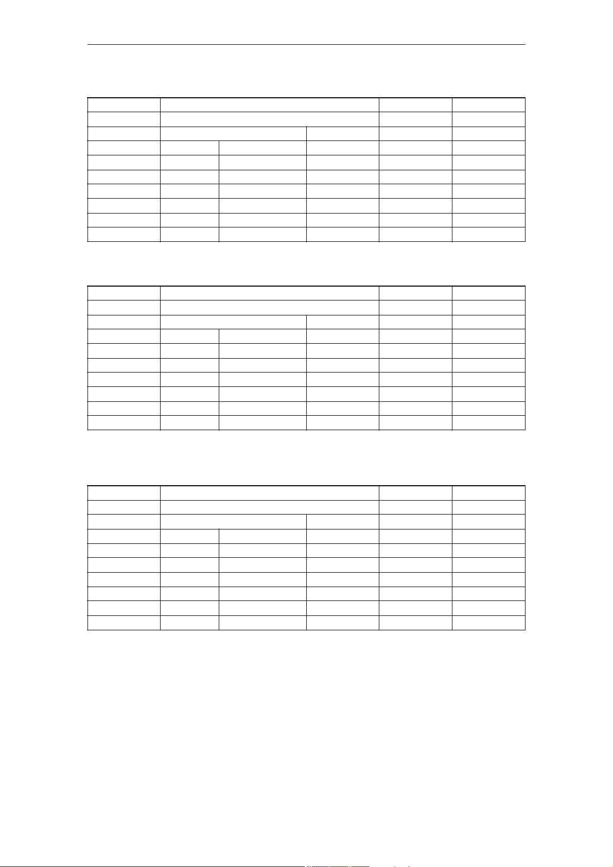
Machine Data 06/2007
Generale maschine data
14512 USER_DATA_HEX N03 A2,P3
- User data (HEX) DWORD POWER ON
-
- 256 0 0 0x0FF 7/2
802d-cu3 32 - - - 7/3
802d-ng2 32 - - - 7/3
802d-ng3 32 - - - 7/3
802d-tm1 32 - - - 7/3
802d-tm2 32 - - - 7/3
802d-tm3 32 - - - 7/3
Description:
User machine data, evaluation in PLC (display in HEX format) 1)
14514 USER_DATA_FLOAT N03 A2,P3
- User data (FLOAT) DOUBLE POWER ON
-
- 32 0.0 -3.40e38 3.40e38 7/2
802d-cu3 8 - - - 7/3
802d-ng2 8 - - - 7/3
802d-ng3 8 - - - 7/3
802d-tm1 8 - - - 7/3
802d-tm2 8 - - - 7/3
802d-tm3 8 - - - 7/3
Description:
User machine data, evaluation in PLC (floating point format, restricted to
32Bit IEEE format in PLC)
14516 USER_DATA_PLC_ALARM N03 A2,P3
- User data (HEX) BYTE POWER ON
-
-640 --0/0
802d-cu3 64 - - - 7/3
802d-ng2 64 - - - 7/3
802d-ng3 64 - - - 7/3
802d-tm1 64 - - - 7/3
802d-tm2 64 - - - 7/3
802d-tm3 64 - - - 7/3
Description:
User data is stored in the NCK-PLC interface and can be evaluated by the PLC
basic system (currently for software PLC 2xx).
2-74
SINUMERIK 802D sl, Parameter Manual, 06/2007 Edition
©Siemens AG 2007 All Rights Reserved
Page 75

06/2007 Machine Data
Generale maschine data
15700 LANG_SUB_NAME N01 -
- Name for substitution subroutine STRING POWER ON
-
-- --7/2
802d-cu3 - - - - 2/2
802d-ng2 - - - - 2/2
802d-ng3 - - - - 2/2
802d-tm1 - - - - 2/2
802d-tm2 - - - - 2/2
802d-tm3 - - - - 2/2
Description:
Name of the user program called on the basis of a substitution configured by
$MA_AXIS_LANG_SUB_MASK.
The user program is called with the path configured by $MN_LANG_SUB_PATH.
15702 LANG_SUB_PATH N01 -
- Call path for substitution subroutine BYTE POWER ON
-
- -0 027/2
802d-cu3 - - - - 2/2
802d-ng2 - - - - 2/2
802d-ng3 - - - - 2/2
802d-tm1 - - - - 2/2
802d-tm2 - - - - 2/2
802d-tm3 - - - - 2/2
Description:
Path with which the user program set by $MN_LANG_SUB_NAME is called on the
basis of a substitution configured by $MA_AXIS_LANG_SUB_MASK:
0: /_N_CMA_DIR (default)
1: /_N_CUS_DIR
2: /_N_CST_DIR
17400 OEM_GLOBAL_INFO A01, A11 -
- OEM version information STRING POWER ON
-
-5 --7/2
802d-cu3 - - - - 2/2
802d-ng2 - - - - 2/2
802d-ng3 - - - - 2/2
802d-tm1 - - - - 2/2
802d-tm2 - - - - 2/2
802d-tm3 - - - - 2/2
Description:
A version information freely available to the user
(is indicated in the version screen)
©Siemens AG 2007 All Rights Reserved
SINUMERIK 802D sl, Parameter Manual, 06/2007 Edition
2-75
Page 76
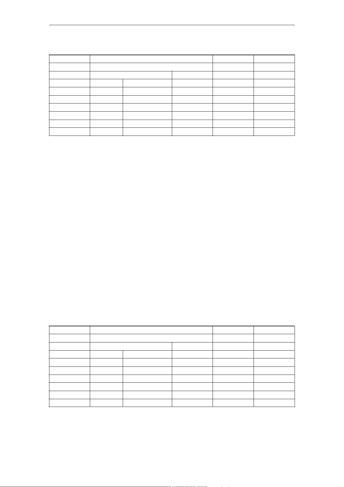
Machine Data 06/2007
Generale maschine data
17530 TOOL_DATA_CHANGE_COUNTER EXP, N01 FBW
- Mark tool data change for HMI DWORD POWER ON
-
--0 00xF7/2
802d-cu3 - - - - 2/2
802d-ng2 - - - - 2/2
802d-ng3 - - - - 2/2
802d-tm1 - - - - 2/2
802d-tm2 - - - - 2/2
802d-tm3 - - - - 2/2
Description:
HMI display support. This data enables individual data to be explicitly taken
into account or not taken into account in the OPI variables (block C/S)
toolCounter, toolCounterC, toolCounterM.
Bit no. Bit value HEX Meaning
------------------------------------------------------------------------------
0 0 Changes to the value of the tool status ($TC_TP8)
are not taken into account in toolCounterC
1 'H1' Changes to the value of the tool status ($TC_TP8)
are taken into account in toolCounterC
1 0 Changes to the remaining number of tools ($TC_MOP4)
are not taken into account in toolCounterC
1 'H2' Changes to the remaining number of tools ($TC_MOP4)
are taken into account in toolCounterC
2 0 Changes to the value of the tool data
are not taken into account in the tool data update
service
1 'H4' Changes to the value of the tool data
are taken into account in the tool data update
service
3 0 Changes to the value of the magazine data
are not taken into account in the tool data update
service
1 'H8' Changes to the value of the magazine data
are taken into account in the tool data update
service.
18030 HW_SERIAL_NUMBER N05 -
- Hardware series number STRING POWER ON
READ
-1 --7/2
802d-cu3 - - - - 2/802d-ng2 - - - - 2/802d-ng3 - - - - 2/802d-tm1 - - - - 2/802d-tm2 - - - - 2/802d-tm3 - - - - 2/-
2-76
SINUMERIK 802D sl, Parameter Manual, 06/2007 Edition
©Siemens AG 2007 All Rights Reserved
Page 77

06/2007 Machine Data
Generale maschine data
Description:
During power on of the control, a unique hardware serial number is stored in
this MD:
- For Powerline series modules this is the serial number of the NCU module
- For Solutionline series modules this is the serial number of the CF card, or
the unique number of the MCI module in the case of PC-based systems
This data cannot be written.
18040 VERSION_INFO N05 IAD
- Version and possibly data of the PCMCIA card, not
FM-NC
READ
Description:
Version identifiers of the system software
The identifiers of the PCMCIA card (assigned by the configuration management)
and the 'system_date_time' from the NCK are stored in this MD during control
power on. A unique assignment can always be made with this data from the MD
block (startup file or INITIAL_INI) to a software release.
STRING POWER ON
18070 INFO_FREE_MEM_DPR EXP, N01, N02,
N05
- Display data of free memory in DUAL PORT RAM DWORD POWER ON
READ
--0 --7/2
802d-cu3 - - - - -1/802d-ng2 - - - - -1/802d-ng3 - - - - -1/802d-tm1 - - - - -1/802d-tm2 - - - - -1/802d-tm3 - - - - -1/-
Description:
Output of the available memory in the Dual Port RAM (Bytes).
The data cannot be written.
18074 MM_TOOL_MANAGEMENT_TRACE_SZ N02, N09 /FBW/,
- Max. size of the tool management diagnostic ring
buffers
-
- 2 25 4 500 7/2
802d-cu3 - - - - -1/802d-ng2 - - - - -1/802d-ng3 - - - - -1/802d-tm1 - - - - -1/802d-tm2 - - - - -1/802d-tm3 - - - - -1/-
DWORD POWER ON
S7
"Description of
Functions, Tool
Management"
©Siemens AG 2007 All Rights Reserved
SINUMERIK 802D sl, Parameter Manual, 06/2007 Edition
2-77
Page 78
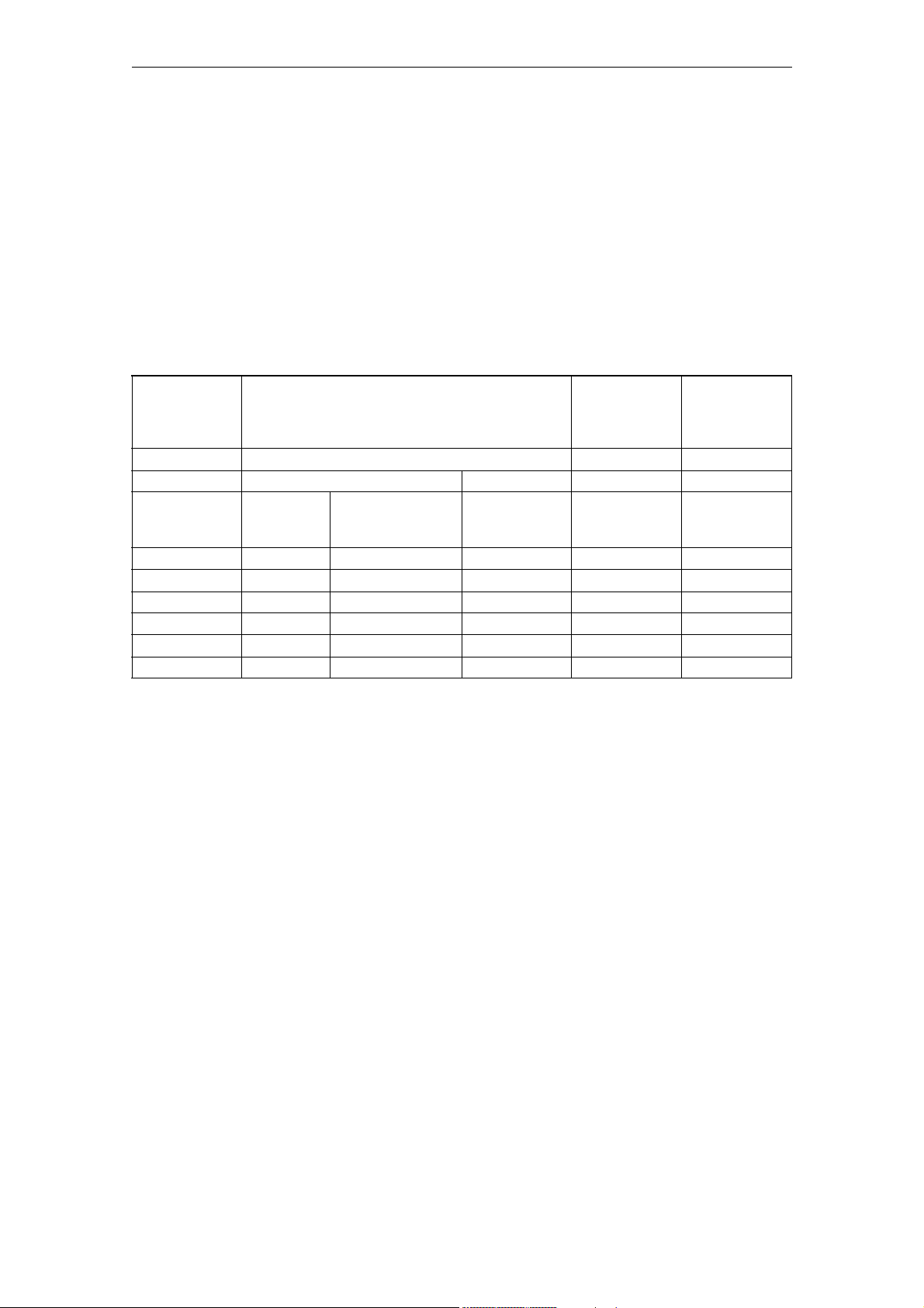
Machine Data 06/2007
Generale maschine data
Description:
The number of entries in the tool management diagnostic ring buffers.
Index 0 = IPO trace buffer size.
Index 1 = Prep trace buffer size.
There are separate IPO trace buffers in each channel, and a Prep trace buffer
in channel 1 only.
The buffers are allocated only if bit 0 (0x0001) is ON at warm start, in both
MD 18080: MM_TOOL_MANAGEMENT_MASK and per-channel MD 20310:
TOOL_MANAGEMENT_MASK.
Trace data is written to the buffers when bit 13 (0x2000) is ON in per-channel
MD 20310: TOOL_MANAGEMENT_MASK.
18075 MM_NUM_TOOLHOLDERS N02, N09 /FBW/,
"Description of
Functions, Tool
Management"
- Max. number of tool holders per TOA DWORD POWER ON
-
- - 32 1 SLMDMAXMAGL
OCATIONSWITH
DISTANCE
802d-cu3 - 6 - 6 -1/802d-ng2 - 6 - 6 -1/802d-ng3 - 6 - 6 -1/802d-tm1 - 4 - 4 -1/802d-tm2 - 6 - 6 -1/802d-tm3 - 6 - 6 -1/-
7/2
Description:
Max. number of definable tool holders per TO range.
The address extension e of commands Te=t, Me=6 (*) is the number of the tool
holder.
t=T number/tool name - depending on the function activated in the NCK.
(*) if: $MC_TOOL_CHANGE_MODE=1 and $MC_TOOL_CHANGE_M_CODE=6 applies
Normally the tool holder of milling machines is a spindle.
Also see $MC_SPIND_DEF_MASTER_SPIND.
For turning machines the tool holder normally is not a spindle axis.
Also see $MC_TOOL_MANAGEMENT_TOOLHOLDER.
In this case it should reasonably apply that $MN_MM_NUM_TOOLHOLDERS is larger
or equal to $MC_SPIND_DEF_MASTER_SPIND/$MC_TOOL_MANAGEMENT_TOOLHOLDER.
If bit 0 = 1 in $MN_MM_TOOL_MANAGEMENT_MASK and $MC_TOOL_MANAGEMENT_MASK is
set (=magazine management (TOOLMAN))
it will apply for reasonable values that $MN_MM_NUM_TOOLHOLDERS is smaller or
equal to $MN_MM_NUM_LOCS_WITH_DISTANCE.
A maximum of $MN_MM_NUM_TOOLHOLDERS intermediate memory locations of the type
2-78
SINUMERIK 802D sl, Parameter Manual, 06/2007 Edition
©Siemens AG 2007 All Rights Reserved
Page 79

06/2007 Machine Data
Generale maschine data
spindle
($TC_MPP1[9998,x]=2) can then be defined.
Example: TOOLMAN inactive
$MC_SPIND_DEF_MASTER_SPIND shall be =3, $MN_MM_NUM_TOOLHOLDERS shall be =3.
Then T1=t, T2=t, T3=t, T=t can be programmed.
Example: TOOLMAN active, milling machine with Me=6 as tool change command
$MN_MM_NUM_TOOLHOLDERS shall be = 14, $MN_MM_NUM_LOCS_WITH_DISTANCE=20,
10 channels shall be active, all channels have TOOLMAN active and have the
same tool and magazine data
(=one TO range for all channels). $MC_SPIND_DEF_MASTER_SPIND=1,.....10 for the
channels.
Then up to 14 locations of the kind 'tool holder'/'spindle' can be defined in
the intermediate magazine memory.
Additional 6 grippers or others can be defined.
These 20 locations max. can be linked to magazines.
In the channels T1=t, .... T14=t and Tt, or M1=6,....M14=6 and M6 can be
programmed.
18076 MM_NUM_LOCS_WITH_DISTANCE N02, N09 /FBW/,
"Description of
Functions, Tool
Management"
- Max. number of magazine locations per TOA with
remote connection
-
- - 32 1 SLMDMAXMAGL
802d-cu3 - 1 - 1 -1/802d-ng2 - 1 - 1 -1/802d-ng3 - 1 - 1 -1/802d-tm1 - 1 - 1 -1/802d-tm2 - 1 - 1 -1/802d-tm3 - 1 - 1 -1/-
DWORD POWER ON
7/2
OCATIONSWITH
DISTANCE
Description:
This machine data is reasonable, if the magazine management function, TOOLMAN,
is active
- See $MN_MM_TOOL_MANAGEMENT_MASK, $MC_TOOL_MANAGEMENT_MASK; for each bit 0 =
1.
Max. number of magazine locations (spindles, load locations,...) per TOA, that
can
have a remote connection to a magazine, defined by $TC_MDPx[n,m].
Example: TOOLMAN shall be active: $MN_MM_NUM_LOCS_WITH_DISTANCE shall be = 5
and $MN_MM_NUM_DIST_REL_PER_MAGLOC = 2.
Two TO units shall be defined with three tool holders/spindles and two load
locations each.
Furthermore, two grippers each shall be defined in each TO unit.
This means that a total of 14 locations shall be defined in the intermediate
memory magazine/load magazine for the distances and assignments.
©Siemens AG 2007 All Rights Reserved
SINUMERIK 802D sl, Parameter Manual, 06/2007 Edition
2-79
Page 80

Machine Data 06/2007
Generale maschine data
4 magazines shall be defined for TO unit 1, 6 magazines for TO unit 2.
With the value set to $MN_MM_NUM_LOCS_WITH_DISTANCE = 5 each tool holder and
each load location
of the two TO units with up to two magazines ($MN_MM_NUM_DIST_REL_PER_MAGLOC =
2) per remote relationship
can be connected; (see $TC_MDP1 and $TC_MDP2) and for each tool holder max.
two more grippers
($MN_MM_NUM_DIST_REL_PER_MAGLOC = 2) can be assigned; (see $TC_MLSR).
One tool holder / one spindle location can subsequently have two tables - one
distance table for magazines and
one assignment table for grippers and similar locations.
18077 MM_NUM_DIST_REL_PER_MAGLOC N02, N09 /FBW/,
"Description of
Functions, Tool
Management"
- Max. no. of magazines in the distance table of a
magazine loc.
-
- - SLMDMAXLINKEDM
AGAZINES
802d-cu3 - 0 - 0 -1/802d-ng2 - 0 - 0 -1/802d-ng3 - 0 - 0 -1/802d-tm1 - 0 - 0 -1/802d-tm2 - 0 - 0 -1/802d-tm3 - 0 - 0 -1/-
0SLMDMAXLINKE
DWORD POWER ON
7/2
DMAGAZINES
Description:
This machine data will only be active, if the magazine management, TOOLMAN
function is active.
- See $MN_MM_TOOL_MANAGEMENT_MASK, $MC_TOOL_MANAGEMENT_MASK.
Two sizes are defined with this magazine data:
1.) Max. number of magazines in the distance table of a magazine location
(spindle, load location, ...)
2.) Max. number of locations (gripper, ...) in the connection table of a
spindle/tool holder location.
Example: $MN_MM_NUM_DIST_REL_PER_MAGLOC shall be = 3.
Two TO units shall be defined with two tool holder/spindles each and one load
location each.
Furthermore four grippers shall be defined in each TO unit.
4 magazines shall be defined for TO unit 1; 6 magazines shall be defined for
TO unit 2.
Then, each tool holder can define max. three distances for the magazines (see
$TC_MDP2)
and additionally a max. of three relationships to the grippers ($TC_MLSR).
2-80
SINUMERIK 802D sl, Parameter Manual, 06/2007 Edition
©Siemens AG 2007 All Rights Reserved
Page 81

06/2007 Machine Data
Generale maschine data
18078 MM_MAX_NUM_OF_HIERARCHIES N02, N09 /FBW/,
"Description of
Functions, Tool
Management"
- The maximum number of hierarchies for magazine
location types
-
- - 8 0 32 7/2
802d-cu3 - - - - -1/802d-ng2 - - - - -1/802d-ng3 - - - - -1/802d-tm1 - - - - -1/802d-tm2 - - - - -1/802d-tm3 - - - - -1/-
Description:
The machine data only has effect if the function 'tool magazine management',
TMMG, is activated - see $MN_MM_TOOL_MANAGEMENT_MASK,
$MC_TOOL_MANAGEMENT_MASK.
The maximum number of hierarchies for magazine location types.
In variable $TC_MPTH[n,m], the allowed range of n is from 0 to
($MN_MM_MAX_NUM_OF_HIERARCHIES - 1).
(The maximum of index m is given by $MN_MM_MAX_HIERARCHY_ENTRIES.)
Value = 0 means that the function 'magazine location type hierchies' is not
available.
DWORD POWER ON
18079 MM_MAX_HIERARCHY_ENTRIES N02, N09 /FBW/,
"Description of
Functions, Tool
Management"
- The max. number of entries in a mag. location type
hierarchy.
-
- - 8 1 32 7/2
802d-cu3 - - - - -1/802d-ng2 - - - - -1/802d-ng3 - - - - -1/802d-tm1 - - - - -1/802d-tm2 - - - - -1/802d-tm3 - - - - -1/-
Description:
The machine data only has effect if the function 'tool magazine management',
TMMG, is activated - see $MN_MM_TOOL_MANAGEMENT_MASK,
$MC_TOOL_MANAGEMENT_MASK - and if $MN_MM_MAX_NUM_OF_HIERARCHIES is greater
than zero.
The maximum number of entries in a magazine location type hierarchy.
In variable $TC_MPTH[n,m], the allowed range of m is from 0 to
($MN_MM_MAX_HIERARCHY_ENTRIES - 1).
(The maximum of index n is given by $MN_MM_MAX_NUM_OF_HIERARCHIES.)
DWORD POWER ON
©Siemens AG 2007 All Rights Reserved
SINUMERIK 802D sl, Parameter Manual, 06/2007 Edition
2-81
Page 82

Machine Data 06/2007
Generale maschine data
18080 MM_TOOL_MANAGEMENT_MASK N02, N09 FBW
- Step-by-step memory reservation for tool
management (SRAM)
-
- - 0x0 0 0xFFFF 7/1
802d-cu3 - - - - 2/2
802d-ng2 - - - - 2/2
802d-ng3 - - - - 2/2
802d-tm1 - - - - 0/0
802d-tm2 - - - - 2/2
802d-tm3 - - - - 2/2
Description:
Step-by-step memory reservation for the tool management (TOOLMAN)
Bit-coded activation data. That is the memory for the TOOLMAN can be activated
in various versions.
The data is evaluated only during startup of the software.
The TOOLMAN data are battery-backed.
The TOOLMAN-specific memory reservation that is defined in detail by the
machine data
MD 18086: $MN_MM_NUM_MAGAZINE_LOCATION
MD 18084: $MN_MM_NUM_MAGAZINE
MD 18096: $MN_MM_NUM_CC_TOA_PARAM
MD 18094: $MN_MM_NUM_CC_TDA_PARAM
MD 18098: $MN_MM_NUM_CC_MON_PARAM
MD 18092: $MN_MM_NUM_CC_MAGLOC_PARAM
MD 18090: $MN_MM_NUM_CC_MAGAZINE_PARAM
is made as a function of this data.
(Further TOOLMAN-specific memory is determined by other machine data, see
below.)
Value = 0 ->None of the above memory is reserved: That is TOOLMAN is not
available, only the basic functionality can be programmed.
DWORD POWER ON
Bit no.HexaMeaning when bit set
value
------------------------------------------------------------------------------
0 (LSB)0x1Tool management data (TMMG) are made available; the memory-reserving
MDs must be set correspondingly ($MN_MM_NUM_MAGAZINE_LOCATION,
$MN_MM_NUM_MAGAZINE). The machine data $MN_MM_NUM_TOOL,
$MN_MM_NUM_CUTTING_EDGES_IN_TOA, which make the memory available for the basic
functionality with and without TOOLMAN, must be set correspondingly. The
TOOLMAN-specific memory is added to the memory determined by $MN_MM_NUM_TOOL.
1 0x2 Monitoring data (TMMO) are made available; the memory-reserving MDs
must be set correspondingly ($MN_MM_NUM_MAGAZINE_LOCATION,
$MN_MM_NUM_MAGAZINE). The memory for the monitoring data is added to the
cutting edges (-> $MN_MM_NUM_CUTTING_EDGES_IN_TOA ).
2 0x4 OEM, CC data (individually determined by $MN_MM_NUM_CC_...) are made
available, the memory-reserving MDs must be set correspondingly.
2-82
SINUMERIK 802D sl, Parameter Manual, 06/2007 Edition
©Siemens AG 2007 All Rights Reserved
Page 83

06/2007 Machine Data
Generale maschine data
3 0x8 Memory reserved for consider adjacent location
4 0x10 Memory and function release for the PI service _N_TSEARC = 'Complex
search for tools in magazines'. Depending on the function characteristic, the
function requires memory of the order of 10KB.
5 0x20 Reserve memory and function release for wear monitoring
6 0x40 The classification of the magazine in wear groups is released
7 0x80 Reserve memory for the adapter of the magazine locations according to
the information in MM_NUM_TOOL_ADAPTER
8 0x100 Reserve memory for sum offsets and/or setup offsets according to the
information in MM_NUM_SUMCORR, MM_KIND_OF_SUMCORR
9 0x200 Value 1 = Tools in a revolver are handled in OPI variable blocks so
that they are not 'shown' on toolholder locations, but always in the revolver
location. That means that, in particular, tools in a revolver no longer leave
their revolver locations when there is a tool change (as far as the display is
concerned).
Value 0 = Default behavior; Tools in a revolver are 'displayed' on the OPI
according to their actual location (as far as the data is concerned).
Example 1:
MM_TOOL_MANAGEMENT_MASK = 1 -> Memory is made available for tool management
data
(TMMG).
MM_TOOL_MANAGEMENT_MASK = 2 -> Memory is made available for monitoring data
(TMMO).
MM_TOOL_MANAGEMENT_MASK = 3 -> Memory is made available for TMMG and TMMO.
MM_TOOL_MANAGEMENT_MASK = 4 -> Memory available for OEM/CC data
MM_TOOL_MANAGEMENT_MASK = 9 -> Memory available for TMMG and
consider adjacent location
MM_TOOL_MANAGEMENT_MASK = 17 -> Memory is made available for TMMG data
and the PI service _N_TSEARC can be used
(decimal 17 = 0x11 = bits 0 and 4)
Example 2:
The complete TOA area has 20 tools and 60 cutting edges. All other abovementioned memory-reserving MDs =0. The TOOLMAN is not active.
Bit 0 (LSB) is now assigned.
The battery-backed memory is deleted after a renewed start of the software
because now additional memory has been reserved for the TOOLMAN. Additional
memory is reserved for each of the 20 tools.
References:
/FBW/, "Description of Functions, Tool Management"
©Siemens AG 2007 All Rights Reserved
SINUMERIK 802D sl, Parameter Manual, 06/2007 Edition
2-83
Page 84

Machine Data 06/2007
Generale maschine data
18084 MM_NUM_MAGAZINE N02, N09 FBW
- Number of magazines the NCK can manage (SRAM) DWORD POWER ON
-
- - 3 0 32 7/2
802d-cu3 - - - - -1/802d-ng2 - - - - -1/802d-ng3 - - - - -1/802d-tm1 - - - - -1/802d-tm2 - - - - -1/802d-tm3 - - - - -1/-
Description:
Number of magazines which the NCK can manage.
Buffered user memory is used.
The MDs for TOOLMAN MD 20310: TOOL_MANAGEMENT_MASK, MD 18080:
MM_TOOL_MANAGEMENT_MASK and the optional TOOLMAN $ON_TECHNO_FUNCTION_MASK must
be set.
Irrelevant:
MD is irrelevant if TOOLMAN is not in use.
Special cases:
Only tool management version 2:
Value = 0 -> TOOLMAN version 2 cannot be activated because no memory area
has been set up for the data.
The battery-backed data are lost if this machine data is altered!
Related to:
MD 18080: MM_TOOL_MANAGEMENT_MASK
(Mask for reserving memory for TOOLMAN)
MD 20310: TOOL_MANAGEMENT_MASK
(Activation of different versions of tool management)
$ON_TECHNO_FUNCTION_MASK
References:
/FBW/, "Description of Functions, Tool Management"
18086 MM_NUM_MAGAZINE_LOCATION N02, N09 FBW
- Number of magazine locations the NCK can manage
(SRAM)
-
- - 30 0 600 7/2
802d-cu3 - - - - -1/802d-ng2 - - - - -1/802d-ng3 - - - - -1/802d-tm1 - - - - -1/802d-tm2 - - - - -1/802d-tm3 - - - - -1/-
DWORD POWER ON
2-84
SINUMERIK 802D sl, Parameter Manual, 06/2007 Edition
©Siemens AG 2007 All Rights Reserved
Page 85

06/2007 Machine Data
Generale maschine data
Description:
Number of magazine locations which the NCK can manage.
Buffered user memory is used.
The MDs for TOOLMAN MD 20310: TOOL_MANAGEMENT_MASK, MD 18080:
MM_TOOL_MANAGEMENT_MASK and the optional TOOLMAN $ON_TECHNO_FUNCTION_MASK must
be set.
Irrelevant:
MD is irrelevant if TOOLMAN is not in use.
Special cases:
Only tool management version 2:
Value = 0 -> tool management version 2 cannot be activated because no
memory area has been set up for the data.
The battey-backed data are lost if this machine data is altered!
Related to:
MD 18080: MM_TOOL_MANAGEMENT_MASK
(Mask for reserving memory for TOOLMAN)
MD 20310: TOOL_MANAGEMENT_MASK
(Activation of different versions of tool management)
$ON_TECHNO_FUNCTION_MASK
References:
/FBW/, "Description of Functions, Tool Management"
18090 MM_NUM_CC_MAGAZINE_PARAM N02, N09 FBW
- Number of magazine data generated and evaluated
by the CC (SRAM)
-
- - 0 0 10 2/2
802d-cu3 - - - - -1/802d-ng2 - - - - -1/802d-ng3 - - - - -1/802d-tm1 - - - - -1/802d-tm2 - - - - -1/802d-tm3 - - - - -1/-
Description:
Only if MD $MN_MM_TOOL_MANAGEMENT_MASK, bit 0=1 (0x1) and bit 2=1 (0x4), is
set for TMMG (and option is set):
Number of magazine data (format IN_Int.) which are created and can be
evaluated by compile cycles.
See also: MM_NUM_MAGAZINE
DWORD POWER ON
©Siemens AG 2007 All Rights Reserved
SINUMERIK 802D sl, Parameter Manual, 06/2007 Edition
2-85
Page 86

Machine Data 06/2007
Generale maschine data
Buffered user memory is used.
Warning:
The battery-backed data are lost if this machine data is altered!
Related to:
MD 18080: MM_TOOL_MANAGEMENT_MASK
(Mask for reserving memory for TOOLMAN)
MD 18084: MM_NUM_MAGAZINE
(Number of magazines managed by the NC)
References:
/FBW/, "Description of Functions, Tool Management"
18091 MM_TYPE_CC_MAGAZINE_PARAM N02, N09 -
- Type of OEM magazine data (SRAM) DWORD POWER ON
-
- 103 162/2
802d-cu3 - - - - -1/802d-ng2 - - - - -1/802d-ng3 - - - - -1/802d-tm1 - - - - -1/802d-tm2 - - - - -1/802d-tm3 - - - - -1/-
Description:
Only when MD $MN_MM_TOOL_MANAGEMENT_MASK, bit 0=1 (0x1) and bit2=1 (0x4), is
set for TMMG (and option is set):
Type of magazine-specific user data configured by MM_NUM_CC_MAGAZINE_PARAM.
Each parameter can be assigned its own type. Permissible types are:
Type Value of machine data
(See types
of the NC language)
--------------------------------------------------------------- BOOL 1
CHAR 2
INT 3
REAL 4
STRING 5 (identifier may be up to 31 characters long)
AXIS 6
FRAME not defined
See also:
MM_NUM_CC_MAGAZINE_PARAM, MM_NUM_MAGAZINE
Buffered user memory is used.
2-86
SINUMERIK 802D sl, Parameter Manual, 06/2007 Edition
©Siemens AG 2007 All Rights Reserved
Page 87

06/2007 Machine Data
Generale maschine data
18092 MM_NUM_CC_MAGLOC_PARAM N02, N09 FBW
- Number of OEM magazine location data (SRAM) DWORD POWER ON
-
- - 0 0 10 2/2
802d-cu3 - - - - -1/802d-ng2 - - - - -1/802d-ng3 - - - - -1/802d-tm1 - - - - -1/802d-tm2 - - - - -1/802d-tm3 - - - - -1/-
Description:
Only if MD $MN_MM_TOOL_MANAGEMENT_MASK, bit 0=1 (0x1) and bit 2=1 (0x4), is
set for TMMG (and option is set):
Number of magazine location data (format IN_int.) which are created for the
memory area and can be evaluated by compile cycles.
Buffered user memory is used.
Irrelevant:
MD is irrelevant if TOOLMAN is not activated
Warning:
The battery-backed data are lost if this machine data is altered!
Related to:
MD 18080: MM_TOOL_MANAGEMENT_MASK
(Mask for reserving memory for TOOLMAN)
MD 18086: MM_NUM_MAGAZINE_LOCATION
References:
/FBW/, "Description of Functions, Tool Management"
18093 MM_TYPE_CC_MAGLOC_PARAM N02, N09 -
- Type of OEM magazine location data (SRAM) DWORD POWER ON
-
- 103 162/2
802d-cu3 - - - - -1/802d-ng2 - - - - -1/802d-ng3 - - - - -1/802d-tm1 - - - - -1/802d-tm2 - - - - -1/802d-tm3 - - - - -1/-
Description:
Only when MD $MN_MM_TOOL_MANAGEMENT_MASK, bit 0=1 (0x1) and bit 2=1 (0x4), is
set for TMMG (and option is set):
©Siemens AG 2007 All Rights Reserved
SINUMERIK 802D sl, Parameter Manual, 06/2007 Edition
2-87
Page 88

Machine Data 06/2007
Generale maschine data
Individual types can be assigned to the parameters in this way. The array
index n can accept values from 0 to the value of MD 18090: MM_NUM_CC_MAGAZINE_PARAM.
The possible values of the MD = 1, 2, 3, 4 and 6 represent the NC language
types
1 BOOL,
2 CHAR,
3 INT,
4 REAL and
6 AXIS
The value 5, type STRING, is here explicitly not possible. The value 5 is
treated like 2. The type FRAME cannot be defined here.
Example:
MD 18090: MM_NUM_CC_MAGAZINE_PARAM=1
MD 18091: MM_TYPE_CC_MAGAZINE_PARAM=2
"A" can then be programmed for the parameter $TC_MPPC1.
Battery-backed working memory is used. A value change can - but need not lead to reconfiguration of the battery-backed memory.
18095 MM_TYPE_CC_TDA_PARAM N02, N09 -
- Type of OEM tool data (SRAM) DWORD POWER ON
-
- 104 162/2
802d-cu3 - - - - 1/1
802d-ng2 - - - - 1/1
802d-ng3 - - - - 1/1
802d-tm1 - - - - -1/802d-tm2 - - - - -1/802d-tm3 - - - - -1/-
Description:
Only when MD $MN_MM_TOOL_MANAGEMENT_MASK, bit 2=1 (0x4), is set:
User or OEM data in the tool management.
Individual types can be assigned to the parameters in this way. The array
index n can accept values from 0 to the value of MD 18094:
MM_NUM_CC_TDA_PARAM.
The possible values of the MD = 1, 2, 3, 4, 5 and 6 represent the NC language
types
1 BOOL,
2 CHAR,
3 INT,
4 REAL,
5 STRING and
6 AXIS.
The type FRAME cannot be defined here. The type STRING can be up to 31
characters long.
Example:
MD 18094: MM_NUM_CC_TDA_PARAM=1
MD 18095: MM_TYPE_CC_TDA_PARAM=5
"UserCuttingEdge" can then be programmed for parameter $TC_TPC1.
Battery-backed working memory is used. A value change can - need not - lead to
reconfiguration of the battery-backed memory.
2-88
SINUMERIK 802D sl, Parameter Manual, 06/2007 Edition
©Siemens AG 2007 All Rights Reserved
Page 89

06/2007 Machine Data
Generale maschine data
18097 MM_TYPE_CC_TOA_PARAM N02, N09 -
- Type of OEM data per cutting edge (SRAM) DWORD POWER ON
-
- 104 162/2
802d-cu3 - - - - 1/1
802d-ng2 - - - - 1/1
802d-ng3 - - - - 1/1
802d-tm1 - - - - -1/802d-tm2 - - - - -1/802d-tm3 - - - - -1/-
Description:
Only when MD $MN_MM_TOOL_MANAGEMENT_MASK, bit 2=1 (0x4), is set:
User or OEM data in the tools.
Type of the cutting-edge-specific user data configured via
MM_NUM_CC_TOA_PARAM. Only the default setting may be used.
Individual types can be assigned to the parameters in this way. The array
index n can accept values from 0 to the value of MD 18096:
MM_NUM_CC_TOA_PARAM.
The possible values of the MD = 1, 2, 3, 4 and 6 represent the NC language
types
1 BOOL,
2 CHAR,
3 INT,
4 REAL and
6 AXIS.
The type FRAME cannot be defined here. (5 STRING is not explicitly possible
here; the value 5 is treated like value 2).
Example:
MD 18096: MM_NUM_CC_TOA_PARAM=1
MD 18097: MM_TYPE_CC_TOA_PARAM=2
"A" can then be programmed for parameter $TC_DPC1
Battery-backed working memory is used. A value change can - but need not lead to reconfiguration of the battery-backed memory.
18099 MM_TYPE_CC_MON_PARAM N02, N09 FBW
- Type of OEM monitor data (SRAM) DWORD POWER ON
-
- 103 162/2
802d-cu3 - - - - -1/802d-ng2 - - - - -1/802d-ng3 - - - - -1/802d-tm1 - - - - -1/802d-tm2 - - - - -1/802d-tm3 - - - - -1/-
©Siemens AG 2007 All Rights Reserved
SINUMERIK 802D sl, Parameter Manual, 06/2007 Edition
2-89
Page 90

Machine Data 06/2007
Generale maschine data
Description:
Individual types can be assigned to the parameters in this way. The array
index n can accept values from 0 to the value of MD 18098: MM_NUM_CC_MON_PARAM
Possible values of the MD = 1, 2, 3, 4 and 6 represent the NC language types
1 BOOL,
2 CHAR,
3 INT,
4 REAL and
6 AXIS.
The FRAME type cannot be defined here.
(5 STRING is not possible explicitly here; the value 5 is treated like value
2).
Example:
MD 18098: MM_NUM_CC_MON_PARAM=1
MD 18099: MM_TYPE_CC_MON_PARAM=2
"A" can then be programmed for the parameter $TC_MOPC1
A battery-backed working memory is used. A value change can - but need not lead to reconfiguration of the battery-backed memory.
18102 MM_TYPE_OF_CUTTING_EDGE N02, N09 W1
- Type of D No. programming (SRAM) DWORD POWER ON
-
- -0 017/2
802d-cu3 - - - - 2/2
802d-ng2 - - - - 2/2
802d-ng3 - - - - 2/2
802d-tm1 - - - - 2/2
802d-tm2 - - - - 2/2
802d-tm3 - - - - 2/2
Description:
This MD activates the 'flat D number management'.
The type of D programming can be determined by individual values:
- direct or
- indirect programming.
The default value is zero. This means that the NCK manages the T and D
numbers.
The NCK only accepts a value > 0 if bit 0 is not set in MD
$MN_MM_TOOL_MANAGEMENT_MASK. That means the tool managment function cannot be
active simultaneously.
Value: Meaning
------------------------------------------------------------------------------
----0: No 'flat D number management' active
1: D numbers are programmed directly and absolutely
2: D numbers are programmed indirectly and relatively.
That means the programmed D number is the index to a table in the VDI. The
PLC writes the absolute D number in this table. The NCK reads this number
and selects the corresponding offset.
2-90
SINUMERIK 802D sl, Parameter Manual, 06/2007 Edition
©Siemens AG 2007 All Rights Reserved
Page 91

06/2007 Machine Data
Generale maschine data
The NCK and PLC are synchronized while doing so. The NCK may have to wait
until the PLC has made the D number(s) available.
The PLC receives the trigger for this by evaluating the T no.
The NC block containing the change command triggers the synchronization and
the waiting for the D numbers.
3 As 2, with simulation of the D numbers by the PLC. Only for testing the NCK
functionality.
In this case, the D numbers are placed by the NCK itself. They can be
assigned via the R parameters R1,...R9. In which case the value of R1 is
mapped onto D1 etc.
Activation (value changed from 0 to > 0) and deactivation (value changed
from > 0 to 0) reconfigure the battery-backed memory, that is delete the
data!
18120 MM_NUM_GUD_NAMES_NCK N02 S7
- Number of global user variable names (SRAM) DWORD POWER ON
-
- - 50 0 32000 7/2
802d-cu3 - - - - 2/2
802d-ng2 - - - - 2/2
802d-ng3 - - - - 2/2
802d-tm1 - - - - 2/2
802d-tm2 - - - - 2/2
802d-tm3 - - - - 2/2
Description:
Defines the number of user variables for NCK global user data (GUD).
Approximately 80 bytes of memory per variable are reserved in the SRAM for the
names of the variables. The additional memory required for the value of the
variable depends on the data type of the variable. The number of available NCK
global user data is exhausted on reaching the limit value set in
MM_NUM_GUD_NAMES_NCK or MD 18150: MM_GUD_VALUES_MEM (memory space for user
variables).
Buffered user memory is used.
Special cases:
The battery-backed data are lost if this machine data is altered.
Related to:
MD 18150: MM_GUD_VALUES_MEM
(Memory space for user variables)
©Siemens AG 2007 All Rights Reserved
SINUMERIK 802D sl, Parameter Manual, 06/2007 Edition
2-91
Page 92
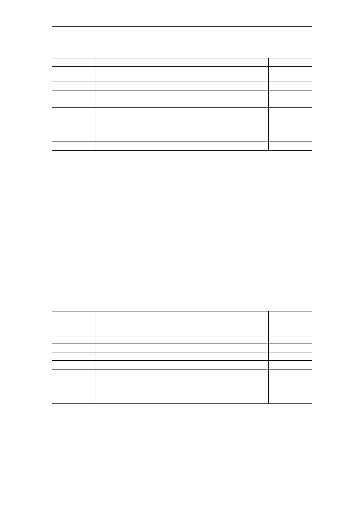
Machine Data 06/2007
Generale maschine data
18130 MM_NUM_GUD_NAMES_CHAN N02 S7
- Number of channel-specific user variable names
(SRAM)
-
- - 150 0 32000 7/2
802d-cu3 - - - - 2/2
802d-ng2 - - - - 2/2
802d-ng3 - - - - 2/2
802d-tm1 - - - - 2/2
802d-tm2 - - - - 2/2
802d-tm3 - - - - 2/2
Description:
Defines the number of user variable names for channel-specific global user
data (GUD). Approximately 80 bytes of memory are reserved in the SRAM for each
variable name. The additional memory required for the value of the variable is
equal to the size of the data type of the variable multiplied by the number of
channels. This means that each channel has its own memory available for the
variable values. The number of available channel-specific global user data is
exhausted on reaching the limit value set in MD 18130: MM_NUM_GUD_NAMES_CHAN
or MD 18150: MM_GUD_VALUES_MEM (memory space for user variables).
DWORD POWER ON
The name created with the DEF statement is valid for all channels.
The memory requirement for the variable value is equal to the size of the data
type multiplied by the number of channels.
Buffered user memory is used.
Special cases:
The battery-backed data are lost if this machine data is altered.
Related to:
MD 18150: MM_GUD_VALUES_MEM
(Memory space for user variables)
18150 MM_GUD_VALUES_MEM N02 S7
- Memory location for global user variable values
(SRAM)
-
- - 32 0 32000 7/2
802d-cu3 - 48 - - 2/2
802d-ng2 - 48 - - 2/2
802d-ng3 - 48 - - 2/2
802d-tm1 - - - - 2/2
802d-tm2 - - - - 2/2
802d-tm3 - - - - 2/2
DWORD POWER ON
Description:
The specified value reserves memory space for the variable values of the
global user data (GUD). The dimensioning of the memory depends to a large
extent on the data types used for the variables.
2-92
SINUMERIK 802D sl, Parameter Manual, 06/2007 Edition
©Siemens AG 2007 All Rights Reserved
Page 93

06/2007 Machine Data
Generale maschine data
Overview of the memory requirements of the data types:
Data type Memory requirement
REAL 8 bytes
INT 4 bytes
BOOL 1 byte
CHAR 1 byte
STRING 1 byte per character, 100 characters permitted per string
AXIS 4 bytes
FRAME up to 1KB depending on control model
The total memory required by a channel or axis-specific global user variable
is the memory requirement of the variables multiplied by the number of
channels or axes. The number of global user variables available is given when
the limit defined in the MD: MM_NUM_GUD_NAMES_xxxx or MM_GUD_VALUES_MEM is
reached.
Buffered user memory is used.
Special cases:
The battery-backed data are lost if this machine data is altered!
Relating to:
MD 18118: MM_NUM_GUD_MODULES:
(Number of GUD blocks)
MD 18120: MM_NUM_GUD_NAMES_NCK
(Number of global user variables)
MD 18130: MM_NUM_GUD_NAMES_CHAN
(Number of channel-specific user variables)
18190 MM_NUM_PROTECT_AREA_NCK N12, N02, N06,
N09
- Number of files for machine-related protection zones
(SRAM)
-
- - 0 0 10 7/2
802d-cu3 - - - - 1/1
802d-ng2 - - - - 1/1
802d-ng3 - - - - 1/1
802d-tm1 - - - - -1/802d-tm2 - - - - -1/802d-tm3 - - - - -1/-
Description:
This machine data defines how many blocks are created for the protection zones
available in the NCK.
DWORD POWER ON
S7
Buffered memory is used.
Special cases:
The battery-backed data are lost if this machine data is altered.
References:
/FB/, A3, "Axis Monitoring, Protection Zones"
©Siemens AG 2007 All Rights Reserved
SINUMERIK 802D sl, Parameter Manual, 06/2007 Edition
2-93
Page 94

Machine Data 06/2007
Generale maschine data
18200 MM_NUM_CCS_MAGAZINE_PARAM N02, N09 FBW
- Number of Siemens OEM magazine data (SRAM) DWORD POWER ON
-
- - 0 0 10 2/2
802d-cu3 - - - - -1/802d-ng2 - - - - -1/802d-ng3 - - - - -1/802d-tm1 - - - - -1/802d-tm2 - - - - -1/802d-tm3 - - - - -1/-
Description:
Only when MD $MN_MM_TOOL_MANAGEMENT_MASK, bit 0=1 ('H1') and bit 2=1 ('H4'),
is set for TMMG (and option is set):
User or OEM data in the tool management (TMMG).
Number of Siemens OEM magazine data (standard format IN_Int).
See also: MM_NUM_CC_MAGAZINE_PARAM, MM_NUM_MAGAZINE
Buffered user memory is used
18201 MM_TYPE_CCS_MAGAZINE_PARAM N02, N09 FBW
- Type of Siemens OEM magazine data (SRAM) DWORD POWER ON
-
- 103 162/2
802d-cu3 - - - - -1/802d-ng2 - - - - -1/802d-ng3 - - - - -1/802d-tm1 - - - - -1/802d-tm2 - - - - -1/802d-tm3 - - - - -1/-
Description:
Only when MD $MN_MM_TOOL_MANAGEMENT_MASK, bit 0=1 ('H1') and bit 2=1 ('H4'),
is set for TMMG (and option is set):
User or OEM data in the tool management.
Type of magazine-specific Siemens user data configured by
MM_NUM_CCS_MAGAZINE_PARAM.
2-94
SINUMERIK 802D sl, Parameter Manual, 06/2007 Edition
©Siemens AG 2007 All Rights Reserved
Page 95
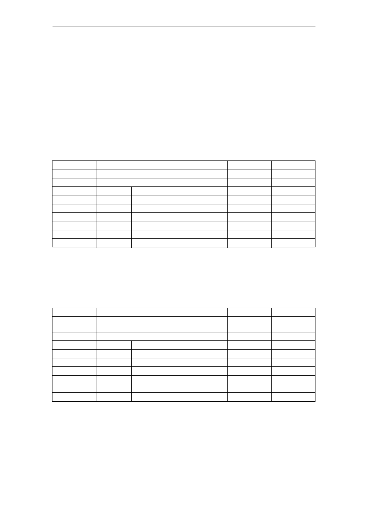
06/2007 Machine Data
Generale maschine data
Each parameter can be assigned its own type. The permissible types are:
Type Value of the machine data
(See types
of the NC language)
---------------------------------------------------------------BOOL 1
CHAR 2
INT 3
REAL 4
STRING 5 (permits identifier up to 31
characters long)
AXIS 6
FRAME not defined
See also: MM_NUM_CCS_MAGAZINE_PARAM, MM_NUM_MAGAZINE
Buffered user memory is used
18202 MM_NUM_CCS_MAGLOC_PARAM N02, N09 FBW
- No. of Siemens OEM magazine location data (SRAM)DWORD POWER ON
-
- - 0 0 10 2/2
802d-cu3 - - - - -1/802d-ng2 - - - - -1/802d-ng3 - - - - -1/802d-tm1 - - - - -1/802d-tm2 - - - - -1/802d-tm3 - - - - -1/-
Description:
Only when MD $MN_MM_TOOL_MANAGEMENT_MASK, bit 0=1 ('H1') and bit 2=1 ('H4'),
is set for TMMG (and option is set):
User or OEM data in the tool management.
Number of Siemens OEM magazine location data (standard format IN_Int).
See also: MM_NUM_CC_MAGLOC_PARAM, MM_NUM_MAGAZINE_LOCATION
Buffered user memory is used
18203 MM_TYPE_CCS_MAGLOC_PARAM N02, N09 FBW
- Type of Siemens OEM magazine location data
(SRAM)
-
- 103 162/2
802d-cu3 - - - - -1/802d-ng2 - - - - -1/802d-ng3 - - - - -1/802d-tm1 - - - - -1/802d-tm2 - - - - -1/802d-tm3 - - - - -1/-
Description:
Only when MD $MN_MM_TOOL_MANAGEMENT_MASK, bit 0=1 ('H1') and bit 2=1 ('H4'),
is set for TMMG (and option is set)
User or OEM data in the tool management.
DWORD POWER ON
©Siemens AG 2007 All Rights Reserved
SINUMERIK 802D sl, Parameter Manual, 06/2007 Edition
2-95
Page 96

Machine Data 06/2007
Generale maschine data
Type of magazine-specific Siemens user data configured by
MM_NUM_CCS_MAGLOC_PARAM.
Each parameter can be assigned its own type. The permissible types are:
Type Value of the machine data
(See types of the NC language)
---------------------------------------------------------------BOOL 1
CHAR 2
INT 3
REAL 4
- (STRING is explicitly impossible here; value 5 is treated like value 2)
AXIS 6
FRAME not defined
See also: MM_NUM_CCS_MAGLOC_PARAM, MM_NUM_MAGLOC
Buffered user memory is used
18209 MM_TYPE_CCS_MON_PARAM N02, N09 FBW
- Type of Siemens OEM monitor data (SRAM) DWORD POWER ON
-
- 103 162/2
802d-cu3 - - - - -1/802d-ng2 - - - - -1/802d-ng3 - - - - -1/802d-tm1 - - - - -1/802d-tm2 - - - - -1/802d-tm3 - - - - -1/-
Description:
Only when $MN_MM_TOOL_MANAGEMENT_MASK, bit 0 = 1 or bit 1 = 1 and bit 2=1
('H4'), is set:
User or OEM data in the tool management.
Type of monitoring-specific Siemens user data configured by
MM_NUM_CCS_MON_PARAM.
Each parameter can be assigned its own type. The permissible types are
Type Value of the machine data
(See types of the NC language)
---------------------------------------------------------------BOOL 1
CHAR 2
INT 3
REAL 4
- (STRING is explicitly impossible here; value 5 is treated like value 2)
AXIS 6
FRAME not defined
See also: MM_NUM_CCS_MON_PARAM, MM_NUM_CUTTING_EDGES_IN_TOA
Buffered user memory is used
2-96
SINUMERIK 802D sl, Parameter Manual, 06/2007 Edition
©Siemens AG 2007 All Rights Reserved
Page 97

06/2007 Machine Data
Generale maschine data
18237 MM_CYC_DATA_MEM_SIZE EXP, N02 -
- Cycle/display setting data in SRAM [kB] DWORD POWER ON
READ
- - 0 0 32000 7/2
802d-cu3 - - - - 1/1
802d-ng2 - - - - 1/1
802d-ng3 - - - - 1/1
802d-tm1 - - - - 1/1
802d-tm2 - - - - 1/1
802d-tm3 - - - - 1/1
Description:
Size of the buffered memory for 'Setting data for cycles and display' [kB]
18238 MM_CC_MD_MEM_SIZE N02 -
- Compile cycle machine data in SRAM [kB] DWORD POWER ON
-
- - 1 1 32000 7/1
802d-cu3 - - - - -1/802d-ng2 - - - - -1/802d-ng3 - - - - -1/802d-tm1 - - - - -1/802d-tm2 - - - - -1/802d-tm3 - - - - -1/-
Description:
Battery-backed user memory for compile cycles (in kbyte)
18800 MM_EXTERN_LANGUAGE N01, N12 FBFA
- Activation of external NC languages DWORD POWER ON
-
- - 0x0000 0x0000 0x0001 7/2
802d-cu3 - 1 - - 1/1
802d-ng2 - - - - -1/802d-ng3 - - - - -1/802d-tm1 - 1 - - 1/1
802d-tm2 - 1 - - 1/1
802d-tm3 - 1 - - 1/1
Description:
The corresponding NC language must be activated to execute part programs of
other control manufacturers. Only one external NC language can be selected.
The range of instructions which is made available in each case is to be taken
from the current documentation.
Bit 0 (LSB):
Execution of part programs ISO_2 or ISO_3.
See $MN_MM_EXTERN_CNC_SYSTEM for coding.
©Siemens AG 2007 All Rights Reserved
SINUMERIK 802D sl, Parameter Manual, 06/2007 Edition
2-97
Page 98

Machine Data 06/2007
Generale maschine data
18890 MM_MAXNUM_3D_PROT_AREAS EXP, N01 -
- Maximum number of elements in 3D protection areasDWORD POWER ON
-
- - 0 - 200 7/2
802d-cu3 - - - - 0/0
802d-ng2 - - - - -1/802d-ng3 - - - - -1/802d-tm1 - - - - -1/802d-tm2 - - - - -1/802d-tm3 - - - - -1/-
Description:
Maximum number of elements in protection zones. If this MD has the value 0
(default value) then no protection zones are possible.
18892 MM_MAXNUM_3D_PROT_AREA_ELEM EXP, N01 -
- Max. number of protection zone elements DWORD POWER ON
-
- - 0 0 1000 7/2
802d-cu3 - - - - 0/0
802d-ng2 - - - - -1/802d-ng3 - - - - -1/802d-tm1 - - - - -1/802d-tm2 - - - - -1/802d-tm3 - - - - -1/-
Description:
Maximum number of protection zone elements. If this MD is 0 (default value),
no protection zones are possible.
18894 MM_MAXNUM_3D_PROT_GROUPS EXP, N01 -
- Max. number of protection zone groups DWORD POWER ON
-
- - 0 0 100 7/2
802d-cu3 - - - - 0/0
802d-ng2 - - - - -1/802d-ng3 - - - - -1/802d-tm1 - - - - -1/802d-tm2 - - - - -1/802d-tm3 - - - - -1/-
Description:
Maximum number of protection zone groups in the system
2-98
SINUMERIK 802D sl, Parameter Manual, 06/2007 Edition
©Siemens AG 2007 All Rights Reserved
Page 99

06/2007 Machine Data
Generale maschine data
18896 MM_MAXNUM_3D_COLLISION EXP, N01 -
- Max. number of temp. memories for collision check DWORD POWER ON
-
- - 0 0 MAX_SIZE_3D_
S_MATRIX_MD
802d-cu3 - - - - 0/0
802d-ng2 - - - - -1/802d-ng3 - - - - -1/802d-tm1 - - - - -1/802d-tm2 - - - - -1/802d-tm3 - - - - -1/-
Description:
Maximum size of a temporary memory area, which is required for the collision
check of two protection zones.
If the two protection zones have m or n elements and a number of machine axes
k, a memory space of 4 * n * m * k elements is required.
Each memory space requires 4 bytes (FLOAT).
If this machine data is 0, the size of the required memory is automatically
derived from machine data $MN_MM_MAXNUM_3D_PROT_AREA_ELEM and
$MN_MM_MAXNUM_3D_PROT_AREAS.
If this memory size is not sufficient, it can explicitly be defined via this
machine data.
7/2
18897 MM_MAXNUM_3D_INTRERFACE_IN EXP, N01 -
- Max. no. of interf. bits for pre-activation of protection
zones
-
- - 16 0 MAXNUM_3D_IN
802d-cu3 - - - - 0/0
802d-ng2 - - - - -1/802d-ng3 - - - - -1/802d-tm1 - - - - -1/802d-tm2 - - - - -1/802d-tm3 - - - - -1/-
Description:
Defines how many input bits are available on the VDI interface for preactivation of 3D protection zones.
It will influence the size of the memory space required for each NC block.
If this machine data has value n, a memory size of approximately n * (n + 1) /
16 bytes will be required per block.
This machine data will be evaluated and will cause reservation of memory
space, only if machine data $MN_MM_MAXNUM_3D_PROT_AREAS is inequal to 0.
DWORD POWER ON
7/1
TERFACEBITS_I
N_MD
©Siemens AG 2007 All Rights Reserved
SINUMERIK 802D sl, Parameter Manual, 06/2007 Edition
2-99
Page 100

Machine Data 06/2007
Generale maschine data
18898 PROT_AREA_3D_TYPE_NAME_TAB EXP, N12, N07 -
- Table of names for protection zone types STRING POWER ON
-
- 10 "BOX","SPHERE","C
YLINDER","CONE"...
802d-cu3 - - - - 0/0
802d-ng2 - - - - -1/802d-ng3 - - - - -1/802d-tm1 - - - - -1/802d-tm2 - - - - -1/802d-tm3 - - - - -1/-
Description:
Contains the names for the protection zone types. The meaning of the entry is
determined by the postition in the list. A change of name does therefore not
cause a change of function.
Meaning of entries:
1. Empty (no protection zone defined)
2. Cuboid
3. Sphere
4. Cylinder
5. Cone
6. Truncated cone
7. Square pyramid
8. Rectangular pyramid
9. Square truncated pyramid
10.Rectangular truncated pyramid
--7/2
Example: If the third entry "SPHERE" is changed into "CUBOID", this new
keyword "CUBOID" still designates a sphere.
A meaningful change would be, for example "SP".
2-100
SINUMERIK 802D sl, Parameter Manual, 06/2007 Edition
©Siemens AG 2007 All Rights Reserved
 Loading...