


32K-X2000
32K-X2000 CK32S60
36K-X2000 CK36S60
SERVICE MANUAL
S68S832KX1000
COLOR TELEVISION
Chassis No. SN-83
32K-X2000
36K-X2000
®
MODELS
In the interests of user-safety (Required by safety regulations in some countries) the set should be restored to its
original condition and only parts identical to those specified should be used.
CK32S60
CK36S60
CONTENTS
Page
» ELECTRICAL SPECIFICATIONS ...........................................................................................................1
» IMPORTANT SERVICE SAFETY PRECAUTION ...................................................................................2
» LOCATION OF USER'S CONTROL.......................................................................................................6
» INSTALLATION AND SERVICE INSTRUCTIONS..................................................................................7
» CHASSIS LAYOUT ...............................................................................................................................16
» DESCRIPTION OF SCHEMATIC DIAGRAM........................................................................................18
» BLOCK DIAGRAM................................................................................................................................ 19
» SCHEMATIC DIAGRAM .......................................................................................................................21
» PRINTED WIRING BOARD ASSEMBLIES ..........................................................................................28
» REPLACEMENT PARTS LIST..............................................................................................................39
» PACKING OF THE SET........................................................................................................................57
ELECTRICAL SPECIFICATIONS
POWER INPUT..................................................... 120V AC 60 Hz
POWER RATING
32K-X2000,CK32S60...................................................... 150W
36K-X2000,CK36S60...................................................... 165W
PICTURE SIZE
32K-X2000,CK32S60.............................. 3,073cm2 (476sq inch)
36K-X2000,CK36S60.............................. 3,905cm2 (605sq inch)
CONVERGENCE ............................................................. Magnetic
SWEEP DEFLECTION .................................................... Magnetic
FOCUS ............................................... Hi-Bi-Potential Electrostatic
INTERMEDIATE FREQUENCIES
Picture IF Carrier Frequency..................................... 45.75 MHz
Sound IF Carrier Frequency...................................... 41.25 MHz
Color Sub-Carrier Frequency .................................... 42.17 MHz
(Nominal)
SHARP CORPORATION
AUDIO POWER OUTPUT RATING
................... 3W + 3W (at 10% distortion and Dual CH Operate)
SPEAKER
SIZE ............................................................... 12 x 6 cm (2 pcs.)
VOICE COIL IMPEDANCE .............................. 6 ohm at 400 Hz
ANTENNA INPUT IMPEDANCE
VHF/UHF.....................................................75 ohm Unbalanced
TUNING RANGES
VHF-Channels...............................................................2 thru 13
UHF-Channels ............................................................14 thru 69
CATV Channels........................................................... 1 thru 125
(EIA, Channel Plan U.S.A.)
Specifications are subject to change without
prior notice.
This document has been published to be used for after
sales service only.
The contents are subject to change without notice.
1
32K-X2000 CK32S60
36K-X2000 CK36S60
Service work should be performed only by qualified service technicians who are
thoroughly familiar with all safety checks and the servicing guidelines which follow:
IMPORTANT SERVICE SAFETY PRECAUTION
WARNING
1. For continued safety, no modification of any circuit
should be attempted.
2. Disconnect AC power before servicing.
3. Semiconductor heat sinks are potential shock
hazards when the chassis is operating.
4. The chassis in this receiver has two ground systems
which are separated by insulating material. The nonisolated (hot) ground system is for the B+ voltage
regulator circuit and the horizontal output circuit. The
isolated ground system is for the low B+ DC voltages
and the secondary circuit of the high voltage
transformer.
To prevent electrical shock use an isolation
transformer between the line cord and power
receptacle, when servicing this chassis.
CAUTION: FOR CONTINUED
PROTECTION AGAINST A
RISK OF FIRE, REPLACE
5A 125V
ONLY WITH SAME TYPE 5A125V FUSE.
SERVICING OF HIGH VOLTAGE SYSTEM
AND PICTURE TUBE
When servicing the high voltage system,
remove the static charge by connecting a
10k ohm resistor in series with an insulated
wire (such as a test probe) between the picture tube ground and the anode lead. (AC
line cord should be disconnected from AC
outlet.)
1. Picture tube in this receiver employs integral
implosion protection.
2. Replace with tube of the same type number for
continued safety.
3. Do not lift picture tube by the neck.
4. Handle the picture tube only when wearing
shatterproof goggles and after discharging the high
voltage anode completely.
X-RADIATION AND HIGH VOLTAGE LIMITS
1. Be sure all service personnel are aware of the
procedures and instructions covering X-radiation. The
only potential source of X-ray in current solid state
TV receivers is the picture tube. However, the picture
tube does not emit measurable X-Ray radiation, if
the high voltage is as specified in the "High Voltage
Check" instructions.
It is only when high voltage is excessive that Xradiation is capable of penetrating the shell of the
picture tube including the lead in the glass material.
The important precaution is to keep the high voltage
below the maximum level specified.
2. It is essential that servicemen have available at all
times an accurate high voltage meter.
The calibration of this meter should be checked
periodically.
3. High voltage should always be kept at the rated value
−no higher. Operation at higher voltages may cause
a failure of the picture tube or high voltage circuitry
and;also, under certain conditions, may produce
radiation in exceeding of desirable levels.
4. When the high voltage regulator is operating properly
there is no possibility of an X-radiation problem. Every
time a colour chassis is serviced, the brightness
should be tested while monitoring the high voltage
with a meter to be certain that the high voltage does
not exceed the specified value and that it is regulating
correctly .
5. Do not use a picture tube other than that specified or
make unrecommended circuit modifications to the
high voltage circuitry.
6. When trouble shooting and taking test measurements
on a receiver with excessive high voltage, avoid being
unnecessarily close to the receiver.
Do not operate the receiver longer than is necessary
to locate the cause of excessive voltage.
2
2
2
2
IMPORTANT SERVICE SAFETY PRECAUTION
(Continued)
32K-X2000 CK32S60
36K-X2000 CK36S60
BEFORE RETURNING THE RECEIVER
(Fire & Shock Hazard)
Before returning the receiver to the user, perform
the following safety checks.
1. Inspect all lead dress to make certain that leads are
not pinched or that hardware is not lodged between
the chassis and other metal parts in the receiver.
2. Inspect all protective devices such as non-metallic
control knobs, insulating materials, cabinet backs,
adjustment and compartment covers or shields,
isolation resistor-capacity networks, mechanical
insulators, etc.
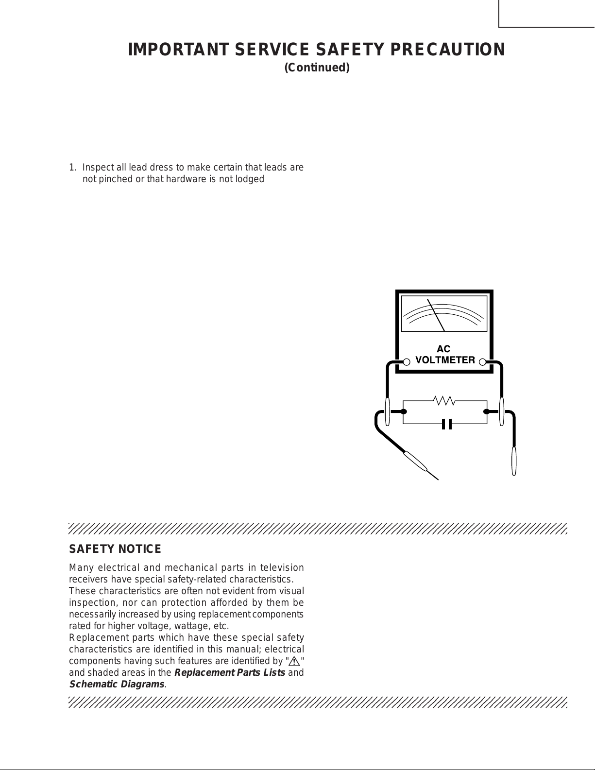
3. To be sure that no shock hazard exists, check for
leakage current in the following manner.
• Plug the AC cord directly into a 120 volt AC outlet,
(Do not use an isolation transformer for this test).
• Using two clip leads, connect a 1.5k ohm, 10 watt
resistor paralleled by a 0.15µF capacitor in series with
all exposed metal cabinet parts and a known earth
ground, such as electrical conduit or electrical ground
connected to earth ground.
• Use an AC voltmeter having with 5000 ohm per volt,
or higher, sensitivity to measure the AC voltage drop
across the resistor.
• Connect the resistor connection to all exposed metal
parts having a return to the chassis (antenna, metal
cabinet, screw heads, knobs and control shafts,
escutcheon, etc.) and measure the AC voltage drop
across the resistor.
AII checks must be repeated with the AC ine cord
plug connection reversed. (If necessary, a nonpolarized adapter plug must be used only for the
purpose of completing these check.)
Any current measured must not exceed 0.5 milliamp.
Any measurements not within the limits outlined
above indicate of a potential shock hazard and
corrective action must be taken before returning the
instrument to the customer.
1.5k ohm
10W
0.15µF
TEST PROBE
TO EXPOSED
METAL PARTS
234567890123456789012345678901212345678901234567890123456789012123456789012345678901234567890121
234567890123456789012345678901212345678901234567890123456789012123456789012345678901234567890121
CONNECT TO
KNOWN EARTH
GROUND
SAFETY NOTICE
Many electrical and mechanical parts in television
receivers have special safety-related characteristics.
These characteristics are often not evident from visual
inspection, nor can protection afforded by them be
necessarily increased by using replacement components
rated for higher voltage, wattage, etc.
Replacement parts which have these special safety
characteristics are identified in this manual; electrical
components having such features are identified by "å"
and shaded areas in the
Schematic Diagrams
234567890123456789012345678901212345678901234567890123456789012123456789012345678901234567890121
Replacement Parts Lists
.
and
For continued protection, replacement parts must be
identical to those used in the original circuit. The use of
substitute replacement parts which do not have the same
safety characteristics as the factory recommended
replacement parts shown in this service manual, may
create shock, fire, X-radiation or other hazards.
3
32K-X2000 CK32S60
36K-X2000 CK36S60
PRECA UTIONS A PRENDRE LORS DE LA REPARATION
Ne peut effectuer la réparation qu' un technicien spécialisé qui s'est parfaitement accoutumé à
toute vérification de sécurité et aux conseils suivants.
AVERTISSEMENT
1. N'entreprendre aucune modification de tout circuit.
C'est dangereux.
2. Débrancher le récepteur avant toute réparation.
3. Les déversoirs thermiques à semi-conducteurs
peuvent présenter un danger de choc électrique
lorsque le réceqteur est en marche.
4. Le châssis de ce récepteur possède deux systèmes
de masse qui sont séparées par du matériel
d'isolation. Le système de masse non-isolée (sous
tension) est pour le circuit du régulateur de tension
B+ et le circuit de sortie horizontale. Le système de
masse isolée est pour les tensions DC B+ basses et
le circuit secondaire du transformateur haute tension.
Pour éviter tout risque d'électrocution lors de
l'entretien de ce châssis, utiliser un transformateur
d'isolation entre le cordon de ligne et la prise de
courant.
PRECAUTION: POUR LA
PROTECTION CONTINUE
CONTRE LES RISQUES
5A 125V
D'INCENDIE, REMPLACER LE
FUSIBLE PAR UN FUSIBLE DE
MEME TYPE 5A-125V.
REPARATION DU SYSTEME A HAUTE TENSION ET DU TUBE-IMAGE
Lors de la réparation de ce systéme, supprimer
la charge statique en branchant une résistance
de 10 kΩ en série avec un fil isolé (comme une
sonde d'essai) entre la mise à la terre du tubeimage et le fil d'anodel. (Le corden
d'alimentation doit être retiré de la prise
murale.)
1. Le tube image dans ce récepteur emploie une
protection intégrée contre l'implosion.
2. Par mesure de sécurité, changer le tube-image pour
un tube du même numéro de type.
3. Ne pas lever le tube-image par son col.
4. Ne manipuler le tube-image qu'en porant des lunettes
incassables et qu'après avoir déchargé totalement
la haute tension.
LIMITES DES RADIATIONS X ET DE LA
HAUTE TENSION
1. Tout le personnel réparateur doit être instruit des
instructions et procédés relatifs aux radiations X.
Le tube-image, seule source de rayons X dons les
téleviseurs transistorisés, n'émet pourtant pas de
rayons mesurables si la haute tension est maintenue
à un niveau préconisé dans la section "Vérification
de la haute tension".
C'est seulement quand la haute tension est excessive
que les rayons X peuvent entrer dans l'enveloppe du
tube-image y compris le conducteur de verre. Il est
important de maintenir la haute tension en-dessous
du niveau spécifié.
2. Il est essentiel que le réparateur ait sous la main un
voltmètre à haute tension qui doit être périodiquement
étalonné.
3. La haute tension doit toujours être maintenue à la
valeur de régime -et pas plus haute. L'opération à
des tensions plus élevées peut entraîner une panne
du tube-image ou du circuit à haute tension et, dans
certaines conditions, peut entraîner une radiation
dépassant les niveaux préscrits.
4. Quand le régulateur à haute tension fonctionne
correctement, il n'y a aucun problème de radiation
X. Chaque fois qu'un châssis couleurs est réparé, la
luminosité doit être examinée bout en contrôlant la
haute tension à l'aide d'un voltmètre pour s'assurer
que la haute tension ne dépasse pas la valeur
spécifiée et qu'elle soit correctement réglée.
5. Ne pas utiliser un tube-image autre que celui spécifié
et ne pas effectuer de modifications déconseillées
du circuit à haute tension.
6. Lors de la recherche des pannes et des mesures
d'essai sur un récepteur qui présente une haute
tension excessive, éviter de s'approcher inutilement
du récepteur.
Ne pas faire fonctionner le récepteur plus longtemps
que nécessaire pour localiser la cause de la tension
excessive.
4
32K-X2000 CK32S60
2
2
2
36K-X2000 CK36S60
PRECAUTIONS A PRENDRE LORS DE LA REPARATION
(Suite)
VERIFICATIONS CONTRE L'INCEN-DIE ET
LE CHOC ELECTRIQUE
Av ant de rendre le récepteur à l'utilisateur, effectuer les
vérifications suivantes.
1. Inspecter tous les faisceaux de câbles pour s'assurer
que les fils ne soient pas pincés ou qu'un outil ne soit
pas placé entre le châssis et les autres pièces
métalliques du récepteur.
2. Inspecter tous les dispositifs de protection comme
les boutons de commande non-métalliques, les
isolants, le dos du coffret, les couvercles ou blindages
de réglage et de compartiment, les réseaux de
résistance-capacité, les isolateurs mécaniques, etc.
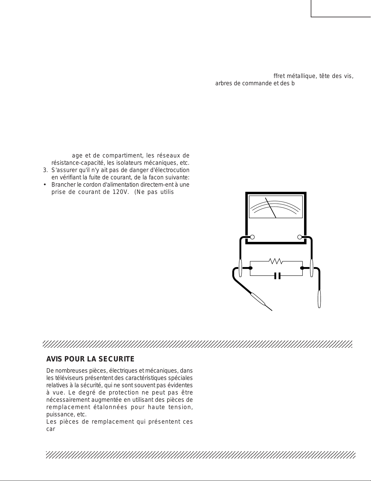
3. S'assurer qu'il n'y ait pas de danger d'électrocution
en vérifiant la fuite de courant, de la facon suivante:
• Brancher le cordon d'alimentation directem-ent à une
prise de courant de 120V. (Ne pas utiliser de
transformateur d'isolation pour cet essai).
• A l'aide de deux fils à pinces, brancher une résistance
de 1,5 kΩ 10 watts en parallèle avec un condensateur
de 0,15µF en série avec toutes les pièces métalliques
exposées du coffret et une terre connue comme une
conduite électrique ou une prise de terre branchée à
la terre.
• Utiliser un voltmètre CA d'une sensibilité d'au moins
5000Ω/V pour mesurer la chute de tension en travers
de la résistance.
• Toucher avec la sonde d'essai les pièces métalliques
exposées qui présentent une voie de retour au
châssis (antenne, coffret métallique, tête des vis,
arbres de commande et des boutons, écusson, etc.)
et mesurer la chute de tension CA en-travers de la
résistance. Toutes les vérifications doivent être
refaites après avoir inversé la fiche du cordon
d'alimentation. (Si nécessaire, une prise d'adpatation
non polarisée peut être utilisée dans le but de terminer
ces vérifications.)
Tous les courants mesurés ne doivent pas dépasser
0,5 mA.
Dans le cas contraire, il y a une possibilité de choc
électrique qui doit être supprimée avant de rendre le
récepteur au client.
V oltmètre CA
1.5k ohm
10W
0.15µF
SONDE D'ESSAI
TEST PROBE
AUX PIECES
TO EXPOSED
METALLIQUES
METAL PARTS
EXPOSEES
234567890123456789012345678901212345678901234567890123456789012123456789012345678901234567890121
BRANCHER A UNE
CONNECT TO
TERRE CONNUE
KNOWN EARTH
GROUND
AVIS POUR LA SECURITE
De nombreuses pièces, électriques et mécaniques, dans
les téléviseurs présentent des caractéristiques spéciales
relatives à la sécurité, qui ne sont souvent pas évidentes
à vue. Le degré de protection ne peut pas être
nécessairement augmentée en utilisant des pièces de
remplacement étalonnées pour haute tension,
puissance, etc.
Les pièces de remplacement qui présentent ces
caractéristiques sont identifiées dans ce manuel; les
pièces électriques qui présentent ces particularités sont
234567890123456789012345678901212345678901234567890123456789012123456789012345678901234567890121
234567890123456789012345678901212345678901234567890123456789012123456789012345678901234567890121
identifiées par la marque " å " et hachurées dans la
liste des pièces de remplacement et les diagrammes
schématiques.
Pour assurer la protection, ces pièces doivent être
identiques à celles utilisées dans le circuit d'origine.
L'utilisation de pièces qui n'ont pas les mêmes
caractéristiques que les pièces recommandées par
l'usine, indiquées dans ce manuel, peut provoquer des
électrocutions, incendies, radiations X ou autres
accidents.
5
32K-X2000 CK32S60
36K-X2000 CK36S60
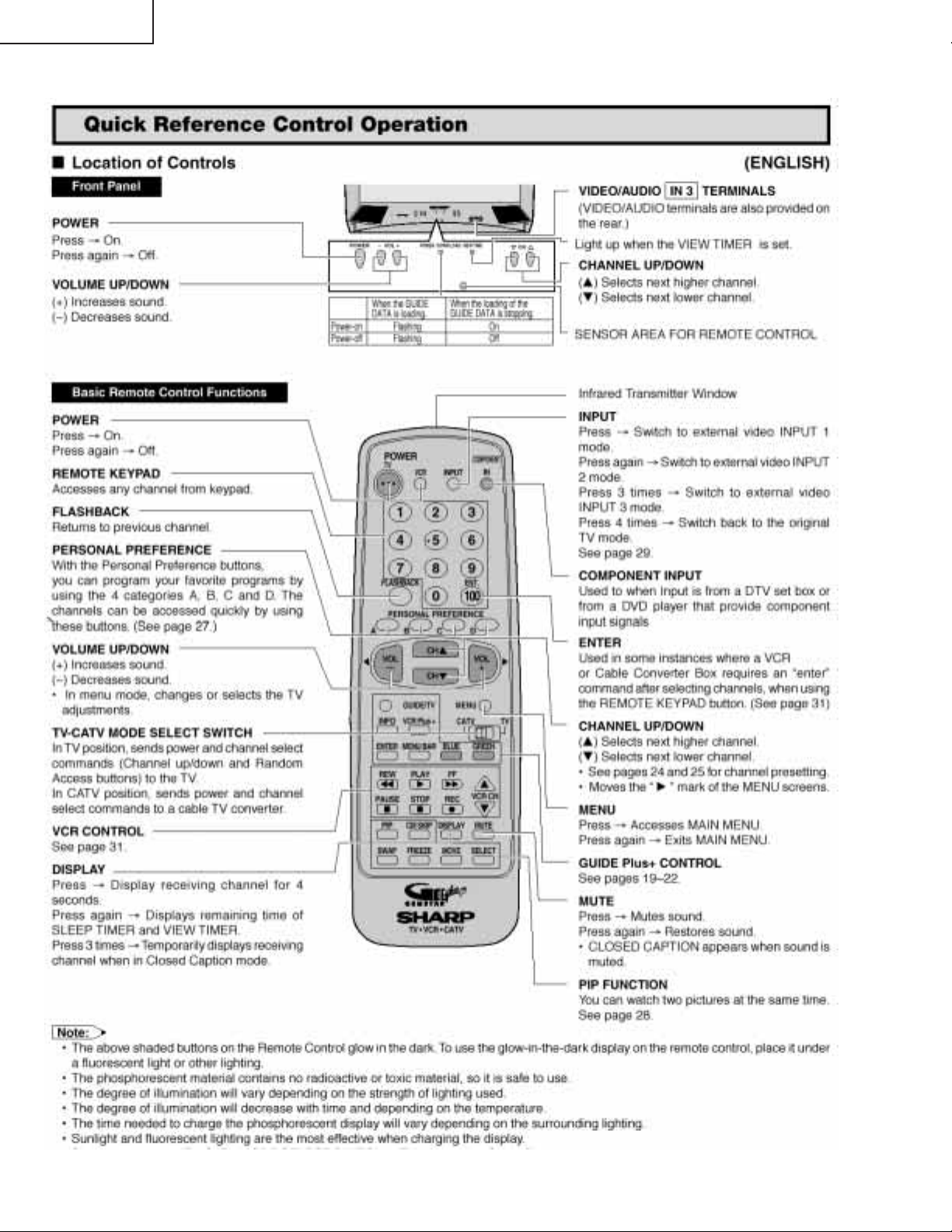
LOCATION OF USER'S CONTROL
6

32K-X2000 CK32S60
36K-X2000 CK36S60
INSTALLATION AND SERVICE INSTRUCTIONS
Note: (1) When performing any adjustments to resistor controls and transformers use non-metallic
screwdrivers or TV alignment tools.
(2) Before performing adjustments, the TV set must be on at least 15 minutes.
CIRCUIT PROTECTION
The receiver is protected by a 5.0A fuse
(F701), mounted on PWB-C, wired into one
side of the AC line input.
X-RADIATION PROTECTOR CIRCUIT TEST
After service has been performed on the horizontal
deflection system, high voltage system, B+ system,
test the X-Radiation protection circuit to ascertain
proper operation as follows:
1) Apply 120V AC using a variac transformer for
accurate input voltage.
2) Allow for warm up and adjust all customer controls
for normal picture and sound.
3) Receive a good local channel.
4) Connect a digital voltmeter to TP653 and make sure
that the voltmeter reads 11.8 ±0.7V.
5) Apply external 14.5V DC at TP653 by using an
external DC supply, TV must be shut off.
6) To reset the protector, unplug the AC cord and plug
the AC cord power on. Now make sure that normal
picture appears on the screen.
7) If the operation of the horizontal oscillator does not
stop in step 5, the circuit must be repaired before the
set is returned to the customer.
HIGH VOLT A GE CHECK
High voltage is not adjustable but must be checked
to verify that the receiver is operating within safe
and efficient design limitations as specified checks
should be as follows:
1. Connect an accurate high voltage meter between
ground and anode of picture tube.
2. Operate receiver for at least 15 minutes at 120V AC
line voltage, with a strong air signal or a properly tuned
in test signal.
3. Enter the service mode and select the service No.
"S21" and Bus data "01" (Y-mute on).
4. The voltage should be approximately, 32.8kV(32KX2000,CK32S60),33.4kV(36K-X2000,CK36S60).
(at zero beam)
If a correct reading cannot be obtained, check circuitry
for malfunctioning components. After the voltage test,
make Y-mute off to the normal mode.
7
32K-X2000 CK32S60
36K-X2000 CK36S60
For adjustments of this model, the bus data is converted to various analog signals by the D/A converter
circuit.
Note: There are still a few analog adjustments in this series such as focus and master screen voltage.
Follow the steps below whenever the service adjustment is required. See "Table-B" to determine, if service adjustments are required.
1. Service Mode
Before putting unit into the service mode, check that
customer adjustments are in the normal mode. Use
the reset function in the video adjustment menu to
ensure customer controls are in their proper (reset)
position.
2. Service Number Selection
Once in the service mode, press the Ch-up or Chdown button on the remote controller or at the set.
The service adjustment number will vary in
increments of one, from "S01" to "G06". Select the
item you wish to adjust.
3. Data Number Selection
Press the Vol-up or down button to adjust the data
number.
SERVICE ADJUSTMENT NUMBER
S01 55 2
To enter the service mode and exit service mode.
While pressing the Vol-up and Ch-up buttons at the
sametime, plug the AC cord into a wall socket.
Now the TV set is switched on and enters the service
mode.
To exit the service mode, turn the television off by
pressing the power button.
DA TA NUMBER
CHANNEL
ANT-B
Figure A.
8
S01 D:00
32K-X2000 CK32S60
36K-X2000 CK36S60
» To call up the service mode, hold down the CH UP and VOL UP keys of the unit at once and plug the AC power
cord into a wall outlet. The unit switches on and comes in the service mode.
» Now hold down both the CH UP and CH DOWN keys of the unit for 2 seconds or longer. the above default values
are written in the EEPROM.
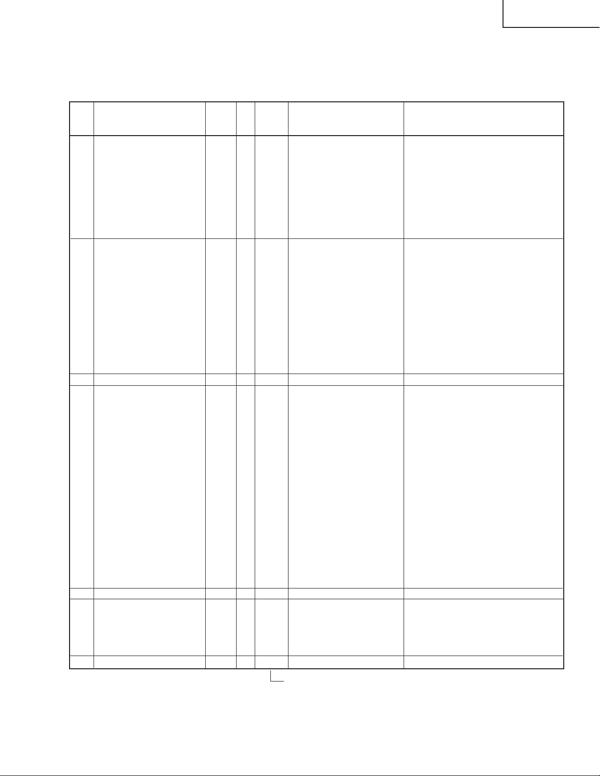
SERVICE
No.
S01 PICTURE HEIGHT 00-127 71 RF signal input (TUNER-B)
S02 V-LINEARITY 00-31 27 " "
S03 V-∫ CORRECTION 00-63 40 40/37 " "
S04 PICTURE WIDTH 00-63 50 " "
S05 E-W PARABOLA 00-63 15 " "
S06 E-W CORNER 00-31 13 " "
S07 TRAPEZIUM 00-127 65 " "
S08 AGC SW 00-01 1 01 " "
S09
S10 TINT 00-63 20 " "
S11 COLOR (SUB COLOR) 00-31 13 " "
S12 BRIGHT (BRIGHTNESS) 00-101 58 " "
S13 SHARP (SHARPNESS) 00-27 5 05/00 " "
S14 V-POSITION 00-07 0 00 " "
S15 H-POSITION 00-31 17 " "
S16 R CUT-OFF 00-255 64 " "
S17 G CUT-OFF 00-255 64 " "
S18 B CUT-OFF 00-255 64 " "
S19 G (R) DRIVE 00-127 64 " "
S20 B DRIVE 00-127 64 " "
S21 Y-MUTE/V-OFF 00-02 0 "
S22 Y-γ CURVE 00-03 0 03 " VCJ IC (IC401) adjusted
S23 VSM PHASE 00-03 1 02 " "
S24 APACON PEAK f0 00-07 1 01 " "
S25 DC RESTORATION RATE 00-63 21 21 " "
S26 DC RESTORATION LIMIT 00-03 0 00 " "
S27 BLACK STRETCH POINT 00-07 3 03 " "
S28 APL VS BPS 00-03 1 01 " "
S29 B.L.C. 00-01 1 01 " "
S30 DYNAMIC ABL POINT 00-07 4 04 " "
S31 DYNAMIC ABL GAIN 00-07 4 04 " "
S32 ABL POINT 00-07 3 03 " "
S33 ABL GAIN 00-07 3 03 " "
S34 Y-DL 00-01 1 00 " "
S35 TOF-f0 00-07 4 07 " "
S36 TOF-Q 00-07 4 04 " "
S37 VSM GAIN 00-03 1 01 " "
S38 OSD SL 00-01 0 00 " "
S39 C-DECODE 00-255 105 161 " "
S40 OSD POSITION 00-15 11 " C. C. display positioning
M01 INPUT LEVEL (ATT) 00-15 7 " MTS IC (IC3001) adjusted
M02 MTS VCO 00-63 37 " "
M03 FILTER 00-63 30 " "
M04 WIDE BAND 00-63 17 " "
M05 SPECTRAL 00-63 22 " "
M06 MTS DATA READ 00-1 0 Note1 " Factory-adjusted only
ADJUSTMENT ITEM INPUT CONDITIONS
PICTURE (SUB CONTRAST)
VARIABLE
00-31 28 " "
DA TA
RANGE
INITIAL
FiXED
VALUE
VALUE
CONTROL DESTINATION
Deflection processor IC (IC502) adjusted
(or EXT. Video input)
00:NORMAL, 01:Y-mute, 03:Hoizontal Y-mute
00/00 is depended on picture size.
Left value : 32K-X2000, CK32S60
Right value : 36K-X2000, CK36S60
Table - A
9
32K-X2000 CK32S60
36K-X2000 CK36S60
SERVICE
No.
P01
P02 PIP TINT (TINT) 00-63 41 37 "
P03
P04 Y-OFFSET (Y_OFFSET) 00-31 9 09 " "
P05 PIP H-POSI (HXA) 00-255 9 10 " "
P06 BGP (HADJ) 00-15 0 00 " "
P07
C01
C02 TINT-C 00-63 20 14 " "
C03 COLOR-C (SUB COLOR) 00-63 13 8 " "
C04
C05 SHARP-C (SHARPNESS) 00-27 5 05/00 " "
C06 V-POSITION-C 00-07 0 00 " "
C07 H-POSITION-C 00-31 19 " "
C08 R CUT-OFF-C 00-255 64 " "
C09 G CUT-OFF-C 00-255 64 " "
C10 B CUT-OFF-C 00-255 64 " "
C11 G (R) DRIVE-C 00-127 64 " "
C12 B DRIVE-C 00-127 64 " "
C13 VSM GAIN-C 00-03 2 02 " "
A01 PICTURE-2 00-31 28 RF signal input (TUNER-A) "
A02 TINT-2 00-63 20 " "
A03 INPUT LEVEL-2 00-15 7 " MTS IC (IC3001) adjusted
A04 WIDE BAND-2 00-63 17 " "
A05 SPECTRAL-2 00-63 22 " "
G01 TVGP+ OSD H-POS1 16-56 30 RF signal input
G02 TVGP+ PIP H X A 00-255 22 RF signal input (Tuner-A. B)
G03 TVGP+ PIP V X A 00-255 6 "
G04 TVGP+ PICTURE HEIGHT 00-10 0 02 "
G05 TVGP+ VD 43-124 94 94/95 "
G06 TVGP+ CHECK 43-124 1 01 "
ADJUSTMENT ITEM INPUT CONDITIONS
PIP Y -LEVEL (CONTRAST)
PIP COLOR (COLOR_SAT)
FREE RUN (FREE_RUN_ADJ)
PICTURE-C (SUB CONTRAST)
BRIGHT-C (BRIGHTNESS)
VARIABLE
00-127 43 " P-IN-P adjusted
00-127 55 RF signal input (TUNER-B) "
00-15 11 11 " "
00-31 28 17 Compornent signal input VCJ IC (IC401) adjusted
00-101 58 " "
DA TA
RANGE
INITIAL
FiXED
VALUE
VALUE
CONTROL DESTINATION
00/00 is depended on picture size.
Left value : 32K-X2000, CK32S60
Right value : 36K-X2000, CK36S60
Note : This item is used only at the manufacturing factory.
Do not change the data. (If this setting is changed to "1", the adjustment data may get wrong.)
Table - A
10

SERVICE ADJUSTMENT
32K-X2000 CK32S60
36K-X2000 CK36S60
Screen Adjustment
1. Receive a good local channel.
2. Enter the service mode and select the service No.
"S11" and set the data value to "00" to set the color
level to minimum. (Record original data code under
No. "S11" before changing) Y ou may skip this step, if
you selected a B/W picture or monoscope pattern.
3. Select the service No. "S21" and adjust the data value
to "01", this turn off the luminance signal (Y-mute).
4. Select the service No. "S12" and adjust data value to
"58".
5. Adjust the master screen control until the raster
darkens to the point where raster is barely seen.
6. Adjust the service numbers "S16" red, "S17" green
and "S18" blue to obtain a good grey scale with normal
whites at low brightness level.
7. Select the service No. "S21" and reset data to "00".
Select the service No. "S11" and reset data to obtain
normal color level.
8. Reset the master screen control to obtain normal
brightness range.
White Balance Adjustment
1. Receive a good local channel.
2. Enter the service mode and select the service No.
"S1 1" and set to "00" (minimum color)(Record original
data code under adjustment "S1 1" before changing).
"S11" does not have to be adjusted, if you selected a
B/W picture or monoscope pattern.
3. Alternately adjust the service numbers "S19" and
"S20" until a good grey scale with normal whites is
obtained.
4. Select the service No. "S1 1" and adjust data to obtain
normal color level.
Sub-Picture Adjustment
1. Receive a good local channel.
2. Make sure the customer picture control is set to
maximum.
3. Enter the service mode and select the service No.
"S09".
4. Adjust the data value to achieve normal contrast
range.
5. Receive the same local channel through the antenna
A.
6. Adjust the "A01" setting to achieve the same contrast
as that with the antenna B.
Sub-Tint Adjustment
1. Receive a good local channel.
2. Set customer tint control to center of it's range.
3. Enter the service mode and select the service No.
"S10".
4. Adjust "S10" data value to obtain normal flesh tones.
5. Receive the same local channel through the antenna
A.
6. Adjust the "A02" setting to achieve the same tint as
that with the antenna B.
Sub-Color Adjustment
1. Receive a good local channel.
2. Make sure the customer color control is set to center
position .
3. Enter the service mode and select the service No.
"S11".
4. Adjust "S11" data value to obtain normal color level.
Sub-Brightness Adjustment
1. Receive a good local channel.
2. Make sure the customer brightness control is set to
center position.
3. Enter the service mode and select the service No.
"S12".
4. Adjust "S12" data value to obtain normal brightness
level.
5. Enter the same data value as the "S12" setting to
"C04".
Vertical Linearity Adjustment
1. Receive a good CATV channel.
2. Set to standard setting mode.
3. Enter the service mode and select the service No.
"S02".
4. While observing the top and bottom of the screen,
adjust "S02" data value to proper vertical linearity.
Vertical Phase Adjustment
1. Enter the service mode and select the service No.
"S14".
2. Adjust data value to "00".
Note: This must be set "00" when changed data
retrace line will appear.
11
32K-X2000 CK32S60
36K-X2000 CK36S60
Vertical-Size Adjustment
1. Receive a good local channel.
2. Enter the service mode and select the service No.
"S01".
3. While observing the top and bottom of the screen,
adjust "S01" data value to proper vertical size.
Side Pincushion Adjustment
1. Receive a good CATV channel or crosshatch pattern
signal.
2. Set to standard setting mode.
3. Enter the service mode and select the service No.
"S05".
4. Adjust the data of service No. "S05" so that the
outermost line on the screen be straight.
Horizontal Position Adjustment
1. Receive a good CATV channel or crosshatch pattern
signal.
2. Set to standard setting mode.
3. Enter the service mode and select the service No.
"S15".
4. Adjust so that the left and right overscans are equal
to each other.
Horizontal Size Adjustment
1. Receive a good CATV channel or crosshatch pattern
signal.
2. Set to standard setting mode.
3. Enter the service mode and select the service No.
"S04".
4. Vary the data of service No. "S04" to obtain the best
horizontal size.
Trapezoidal Distortion Adjustment
1. Receive a good CATV channel or crosshatch pattern
signal.
2. Set to standard setting mode.
3. Enter the service mode and select the service No.
"S07".
4. Adjust so that the leftmost and rightmost vertical lines
are parallel to each other.
Corner Distortion Adjustment
1. Receive a good CATV channel or crosshatch pattern
signal.
2. Set to standard setting mode.
3. Enter the service mode and select the service No.
"S06".
4. Adjust so that the vertical lines should be straight.
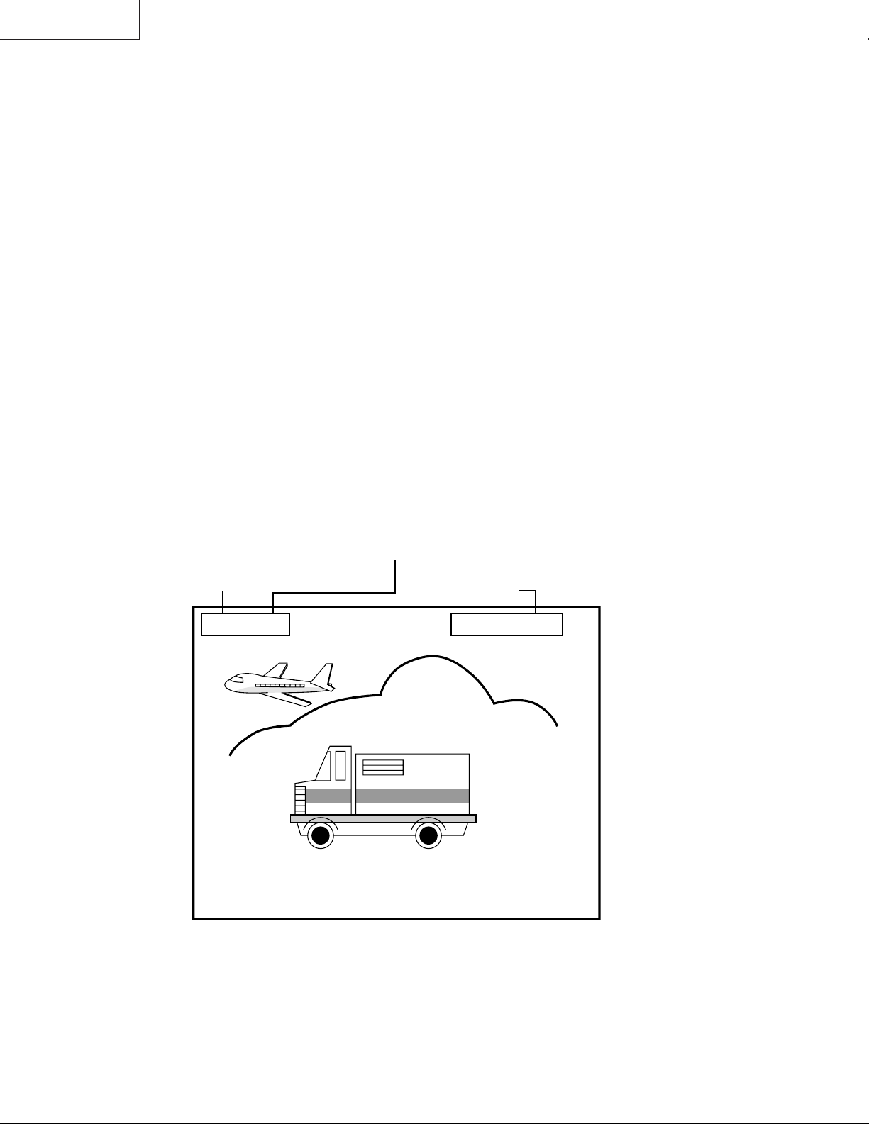
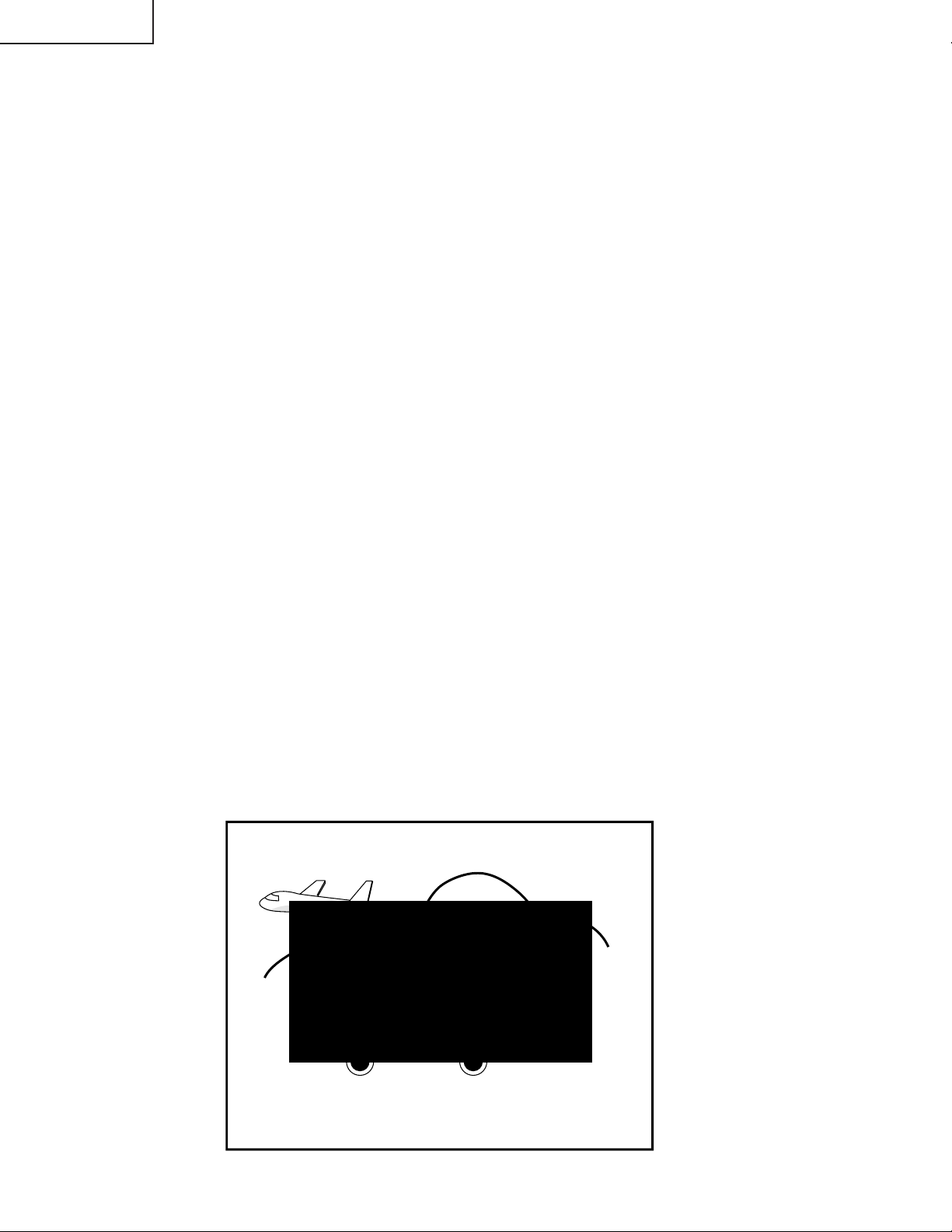
Caption Position Adjustment (Horizontal)
1. Receive a good local channel.
2. Enter the service mode and select the service No.
"S40".
3. A black text box appears on the screen. (see Figure
B below)
4. Adjust "S40" data value so that text box is positioned
in the center of the screen.
Sharpness Adjustment
1. Receive a good local channel.
2. Enter the service mode and select the service No.
"S13".
3. Adjust data value to "05" (32K-X2000/CK32S60)
"00"(36K-X2000/CK36S60).(center of data range)
Figure B.
12

32K-X2000 CK32S60
36K-X2000 CK36S60
MTS ADJUSTMENT
MTS Level Adjustment
1. Feed the following monaural signal to pin (14) of
IC3001.
Monaural signal : 300Hz, 245mVrms
2. Connect the rms voltmeter to pin (39) of IC3001.
3. Enter the service mode and select the service No.
"M01"(Antenna B) and "A03"(Antenna A).
4. Adjust the data so that the rms voltmeter reads.
Spec : 490 ±10mVrms.
MTS VCO Adjustment
1. Keep the unit in no-signal state.
2. Connect the frequency counter to pin (39) of IC3001.
3. Connect a capacitor (100µF, 50V) in between
positive(+) side of C3005 and ground.
4. Enter the service mode and select the service No.
"M02"
5. Adjust the data so that the frequency counter reads.
Spec : 62.94 ±0.75kHz.
Filter Adjustment
1. Feed the following stereo pilot signal to pin (14) of
IC3001 .
Stereo pilot signal: 9.4kHz, 600mVrms.
2. Enter the service mode and select the service No.
"M03".
3. Adjust the data until "OK" appears in position on the
screen. Make sure the "OK" is displayed almost at
the center of the data range.
Separation Adjustment
1. Connect the rms voltmeter to pin (39) of IC3001.
2. Receive the following composite stereo signal 1.
Composite stereo signal: 30% modulation, left
channel only, noise reduction on, 300Hz
3. Enter the service mode and select the service No.
"M04"(Antenna B).
4. Adjust the data until the AC voltage reading of the
rms voltmeter is minimum.
5. Receive the following composite stereo signal 2.
Stereo signal: 30% modulation, left channel only,
noise reduction on, 3kHz
6. Enter the service mode and select the service No.
"M05"(Antenna B).
7. Adjust the data until the AC voltage reading of the
rms voltmeter is minimum.
8. Take the above steps 1 thru 7 again for fine
adjustment.
9. Enter the service mode and select the service
No."A04"(Antenna A).
10.Adjust the data until the AC voltage reading of the
rms voltmeter is minimum.
11.Receive the following composite stereo signal 2.
Stereo signal: 30% modulation, left channel only,
noise reduction on, 3kHz
12.Enter the service mode and select the service
No."A05"(Antenna A).
13.Adjust the data until the AC voltage reading of the
rms voltmeter is minimum.
14.T ake the above steps 9 to 13 again for fine adjustment.
P-IN-P ADJUSTMENT
P-IN-P Y LEVEL Adjustment
1. Receive a good local channel.
2. Enter the service mode and select the service No.
"P01".
3. Adjust "P01" data value to obtain normal contrast
level.
P-IN-P TINT Adjustment
1. Receive a good local channel.
2. Enter the service mode and select the service No.
"P02".
3. Adjust data value to "37".
P-IN-P COLOR Adjustment
1. Receive a good local channel.
2. Make sure the customer color control is set to center
position.
3. Enter the service mode and select the service No.
"P03".
4. Adjust "P03" data value to obtain normal color level.
P-IN-P Y-OFF SET Adjustment
1. Receive a good local channel.
2. Enter the service mode and select the service No.
"P04".
3. Adjust data value to "09".
P-IN-P H-POSITION Adjustment
1. Receive a good local channel.
2. Enter the service mode and select the service No.
"P05".
3. Adjust data value to "10".
P-IN-P BURST GATE PULSE (for MAIN)
1. Receive a good local channel.
2. Enter the service mode and select the service No.
"P06".
3. Adjust data value to "00".
P-IN-P FREE RUN
1. Receive a good local channel.
2. Enter the service mode and select the service No.
"P07".
3. Adjust data value to "11".
13
32K-X2000 CK32S60
36K-X2000 CK36S60
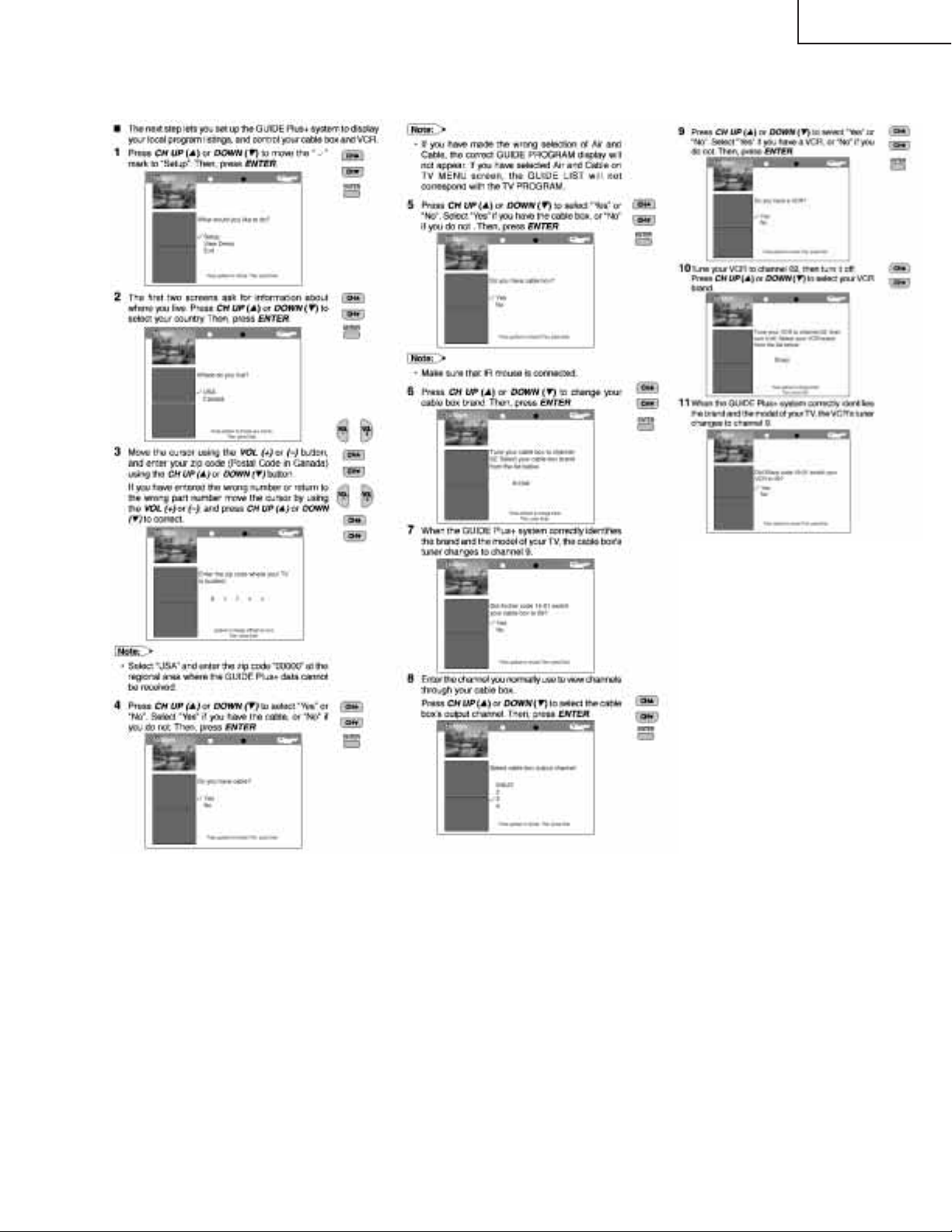
GUIDE Plus+ Adjustment
1. Bus Data Setting
1) Picture Height Adjustment
•Enter the Service Mode and select Service
Adjustment "G04"
•Match the value of the data to "02"
2) VD Adjustment
•Enter the Service Mode and select Service
Adjustment "G05"
•Match the value of the data to "94" (32K-X2000,
CK32S60) and "95" (36K-X2000, CK36S60).
2. OSD H-position Adjustment
•Input a good channel into Antenna B and another
into Antenna A.
•Enter the Service Mode and select Service
Adjustment "G01".
•GUIDE PLUS+ OSD is displayed on the screen.
•Enable adjustment of the "G01" data bus and
adjust so that GUIDE PLUS+ OSD is centered
on the screen.
3. GUIDE Plus+ PIP Position Adjustment
1) H-position Adjustment
•Input a good channel into Antenna B and another
into Antenna A.
•Enter the Service Mode and select Service
Adjustment "G02"
•GUIDE PLUS+ OSD is displayed on the screen.
•Enable adjustment of the "G02" data bus and
adjust so that the horizontal position of GUIDE
PLUS+ PIP is centered in the display frame of
the screen.
2) V-position Adjustment
•Input a good channel into Antenna B and another
into Antenna A.
•Enter the Service Mode and select Service Adjustment
"G03"
•GUIDE PLUS+ OSD is displayed on the screen.
•Enable adjustment of the "G03" data bus and adjust
so that the vertical position of GUIDE PLUS+ PIP is
centered in the display frame of the screen.
4. GUIDE Plus+ Data Check and Preload Operation
Check
It is necessary to perform these checks when
replacing the microcontroller (IC2001), the GUIDE
Plus+ unit (DUNTK9581WEK0), or the unit
component IC (IC2101, 2102, 2103).
When performing a data check, be sure to connect
signals with the GUIDE Plus+ data overlapped to
Antenna A.
1) ROM and RAM Test
•Input a good channel into Antenna A and another into
Antenna B.
•Enter the Service Mode and select Service Adjustment
"G06".
•TV GUIDE+ data check will start automatically.
•Confirm that "ROM TEST" and "RAM TEST" are
displayed as "Passed 100%".
Change the "G03" data bus and adjust so that the
horizontal position of GUIDE PLUS+ PIP is centered
in the display frame of the screen.
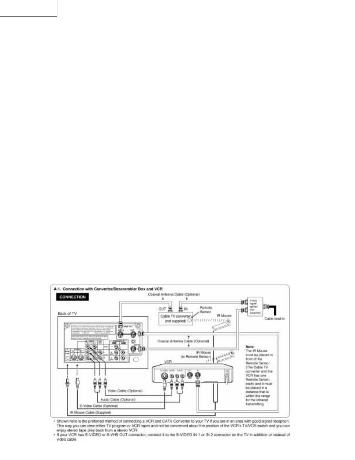
2) IR Operation Confirmation
Connect the IR MOUSE as shown in the illustration
below.
14
Confirm the IR operation in the order listed below.
32K-X2000 CK32S60
36K-X2000 CK36S60
15
 Loading...