


AD6
Manual en Español Latino Americano: |
|
http://www.schwinnfitness.com |
ASSEMBLY MANUAL / OWNER’S MANUAL |

TABLE OF CONTENTS
Important Safety Instructions - Assembly |
3 |
Adjustments |
18 |
Safety Warning Labels / Serial Number |
4 |
Using the Machine |
18 |
Specifications |
5 |
Locking the Fan Assembly / Storage |
19 |
Before Assembly |
5 |
Power Up / Idle Mode |
19 |
Parts |
6 |
Initial Setup |
20 |
Hardware |
7 |
Quick Start Program |
20 |
Tools |
7 |
Custom Time Workout |
20 |
Assembly |
8 |
Pausing or Stopping |
20 |
Moving the Machine |
13 |
Results Mode |
20 |
Leveling the Machine |
13 |
Console Service Mode |
21 |
|
|
Maintenance |
22 |
Important Safety Instructions |
14 |
Replacing the Console Batteries |
23 |
Features |
15 |
Maintenance Parts |
24 |
Console Features |
16 |
Troubleshooting |
25 |
Remote Heart Rate Monitor |
17 |
Warranty |
27 |
Operations |
18 |
|
|
To validate warranty support, keep the original proof of purchase and record the following information:
Serial Number __________________________
Date of Purchase ____________________
To register your product warranty , go to: www.SchwinnFitness.com/register Or call 1 (800) 605–3369.
If you have questions or problems with your product, please call 1 (800) NAUTILUS (628–8458).
Nautilus, Inc., (800) NAUTILUS / (800) 628-8458, www.NautilusInc.com - Customer Service: North America (800) 605-3369, csnls@ nautilus.com | outside U.S. +01-360-859-5180, technics-APLA@nautilus.com | Printed in China | © 2012 Nautilus, Inc.
2

IMPORTANT SAFETY INSTRUCTIONS - ASSEMBLY
This icon means a potentially hazardous situation which, if not avoided, could result in death or serious injury.
Obey the following warnings:
Read and understand all warnings on this machine.
Carefully read and understand the Assembly instructions.
•Keep bystanders and children away from the product you are assembling at all times.
•Do not install the batteries into the machine until the time specified in the assembly manual.
•Do not assemble this machine outdoors or in a wet or moist location.
•Make sure assembly is done in an appropriate work space away from foot traffic and exposure to bystanders.
•Some components of the machine can be heavy or awkward. Use a second person when doing the assembly steps involving these parts. Do not do steps that involve heavy lifting or awkward movements on your own.
•Set up this machine on a solid, level, horizontal surface.
•Do not try to change the design or functionality of this machine. This could compromise the safety of this machine and will void the warranty.
•If replacement parts are necessary use only genuine replacement parts and hardware supplied by Nautilus. Failure to use genuine replacement parts can cause a risk to users, keep the machine from operating correctly and void the warranty.
•Do not use or put the machine into service until the machine has been fully assembled and inspected for correct performance in accordance with the Manual.
•Read and understand the complete Manual supplied with this machine before first use. Keep the Manual for future reference.
•Do all assembly steps in the sequence given. Incorrect assembly can lead to injury or incorrect function.
•This product contains magnets. Magnetic fields can interfere with the normal use of certain medical devices at a close range. Users may come into proximity of the magnets in the assembly, maintenance, and/or use of the product. Given the obvious importance of these devices, such as a pacemaker, it is important that you consult with your medical provider in connection with the use of this equipment. Please consult the “Safety Warning Labels and Serial Number” section to determine the location of the magnets on this product.
3
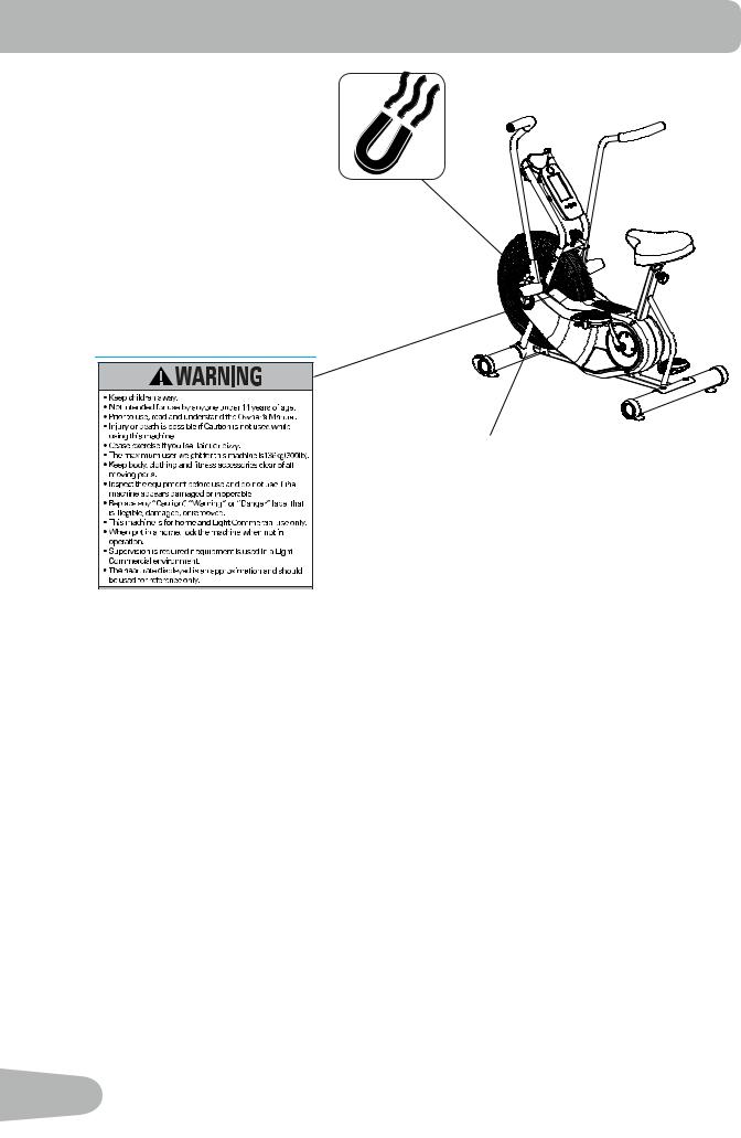
SAFETY WARNING LABELS AND SERIAL NUMBER
Serial number Product specification
4
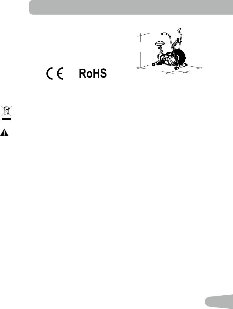
SPECIFICATIONS
Machine Weight: |
115 lbs. (52.2 kg) |
|
|
Power Requirements: |
2 AA Batteries |
|
|
Operating Voltage: |
1.0 - 3.3VDC |
50.9” |
|
|
|
|
|
Maximum User Weight: |
300 lbs. (136 kg) |
(129.2 cm) |
|
|
|
||
Regulatory Approvals: |
|
49.7” |
25.7” |
|
|
||
|
|
(126.3 cm) |
(65.2 cm) |
This product conforms to the applicable EN ISO 20957 International Standards for Stationary Training Equipment, Class S
DO NOT dispose of this product as refuse. This product is to be recycled. For information on the proper method of disposal, contact a Nautilus Customer Service Representative. Contact information is available in the Contacts section in this manual.
This product, its packaging, and components contain chemicals known to the State of California to cause cancer, birth defects, or reproductive harm. This Notice is provided in accordance with California’s Proposition 65. If you would like additional information, please refer to our website at www.nautilus.com/prop65.
Before Assembly
Select the area where you are going to set up and operate your machine. For safe operation, the location must be on a hard, level surface. Allow a workout area of a minimum 73.7” (187.2 cm) x 97.7” (248.2 cm).
Basic Assembly Tips
Follow these basic points when you assemble your machine:
•Read and understand the “Important Safety Instructions” before assembly.
•Collect all the pieces necessary for each assembly step.
•Using the recommended wrenches, turn the bolts and nuts to the right (clockwise) to tighten, and the left (counterclockwise) to loosen, unless instructed otherwise.
•When attaching 2 pieces, lightly lift and look through the bolt holes to help insert the bolt through the holes.
•The assembly requires 2 people.
5
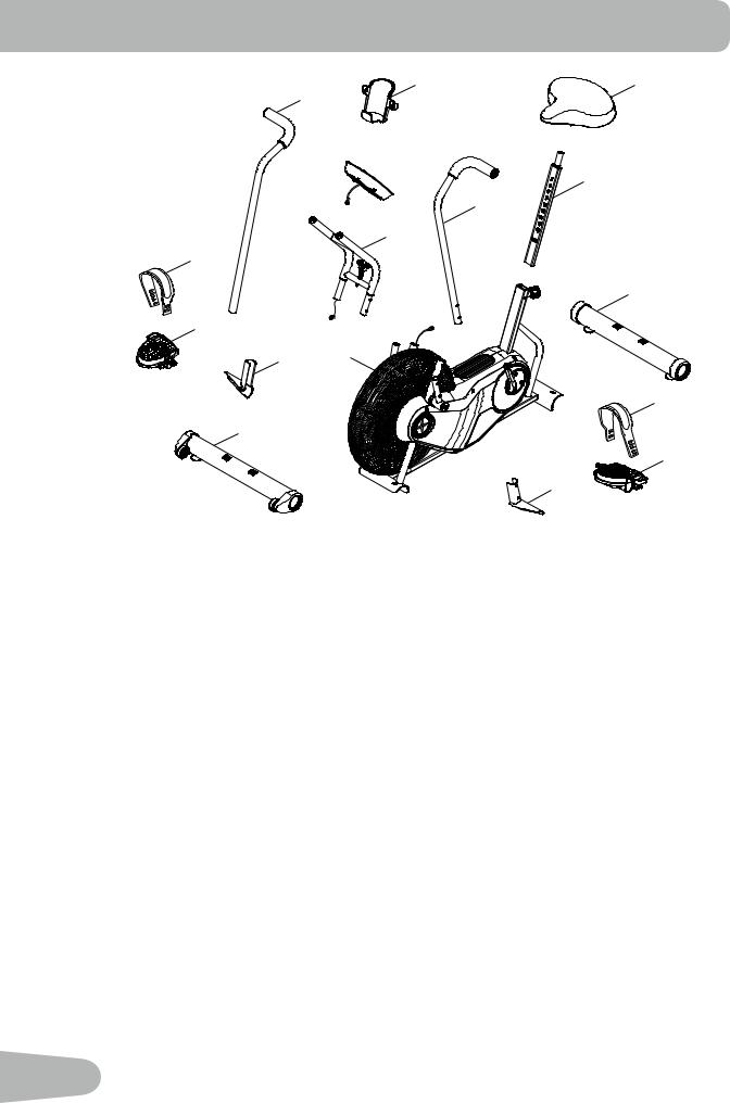
PARTS
R
17 |
4 |
6 |
16 |
|
3  7
7
5
2 |
STOP |
15
8
14
13 1
9
12
10
11
A decal has been applied to all right (“ R ”) and left (“ L ”) parts to assist with assembly.
Item |
Qty |
Description |
Item |
Qty |
Description |
1 |
1 |
Frame |
9 |
1 |
Pedal Strap, Left |
2 |
1 |
Console Support Bar |
10 |
1 |
Pedal, Left |
3 |
1 |
Console |
11 |
1 |
Foot Peg, Left |
4 |
1 |
Water Bottle Holder |
12 |
1 |
Stabilizer, Front |
5 |
1 |
Handlebar, Left |
13 |
1 |
Foot Peg, Right |
6 |
1 |
Seat |
14 |
1 |
Pedal, Right |
7 |
1 |
Seat Post |
15 |
1 |
Pedal Strap, Right |
8 |
1 |
Stabilizer, Rear |
16 |
1 |
Handlebar, Right |
6
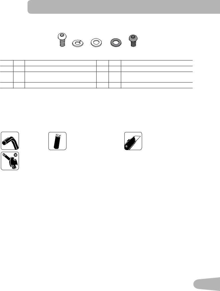
HARDWARE / TOOLS
|
|
A |
B |
C |
D |
|
E |
Item |
Qty |
Description |
|
|
Item |
Qty |
Description |
A |
4 |
Button Head Hex Screw, M8x1.25x20 |
D |
4 |
Washer, M8 Black |
||
B |
4 |
Washer, M8 Lock |
|
|
E |
4 |
Button Head Hex Screw, M8x1.25x12 |
|
|
|
|
|
|
|
Black |
C |
4 |
Washer, M8 |
|
|
|
|
|
Tools
Included |
|
Not Included |
6 mm |
2 AA size batteries (LR6) |
(recommended) |
#2
13 mm
15 mm
17 mm
7

ASSEMBLY
1. Attach Stabilizers to Frame
Note: Hardware is pre-installed and not on the Hardware Card ( * ).
6mm 
X4
* |
8 |
|
|
* |
|
1
12
2. Attach Pedals and then Pedal Straps to Frame Assembly
Note: The Left Pedal is reverse-threaded. Be sure to attach Pedals on the proper side of the Bike. Orientation is based from
a seated position on the bike. The Left Pedal has an “L”, the Right Pedal an “R”.
15
14 |
R |
|
9
10
X2
8
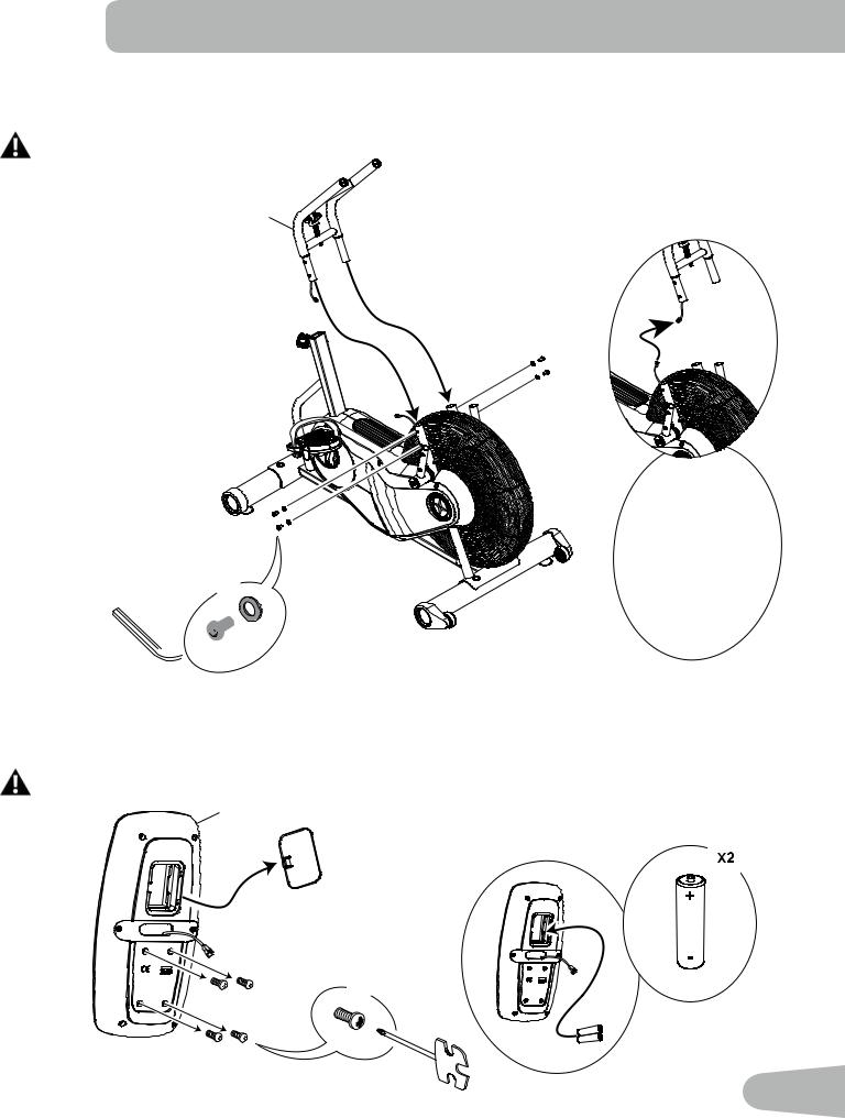
3. Connect Cables and Attach the Console Support Bar to Frame Assembly
Note: Do not crimp the cables. Pull the lower cable to remove any slack as you insert the Console Support Bar.
In order to avoid possible serious injury, when inserting the tube ends into the Frame Assembly be careful to avoid fingers or hands being caught or pinched.
2
X4


 D 6mm
D 6mm 
 E
E
4. Remove Hardware and Install Batteries into Console
Note: Make sure that the batteries point in the direction of the +/– indicators in the battery bay. Hardware is pre-installed and not on the Hardware Card ( * ).
Do not mix alkaline, standard (carbon-zinc), or rechargeable (Ni-Cd, Ni-MH, etc) batteries.
3
X4
*
#2
9
 Loading...